please submit your paper in microsoft
TRANSCRIPT

COVER SHEET NOTE: This coversheet is intended for you to list your article title and author(s) name only
—this page will not appear on the CD-ROM.
Paper Number: 3505 (replace with your paper number)
Title: Buckling Design and Imperfection Sensitivity of Sandwich Composite
Launch-Vehicle Shell Structures
Authors: Marc R. Schultz
David W. Sleight
David E. Myers
W. Allen Waters, Jr.
Prasad B. Chunchu
Andrew E. Lovejoy
Mark W. Hilburger
<<All text below on this page can be deleted >>
PAPER DEADLINE: **June 17, 2016**
PAPER LENGTH: **6-16 PAGES (Maximum – not counting cover page) **
SUBMISSION PROCEDURE: Information on the electronic submission of
manuscripts is provided on the conference web site
http://mech.utah.edu/ASC2016/
FILE NAME: PaperNo_LastName(1st author).doc Example: 9999_Deraco.doc
Please be sure to read these Guidelines prior to preparing your paper—this will
ensure your paper is consistent with the format of the articles in the CD-ROM.
NOTES:
- Use this document file as a template to prepare your paper
- 1st page will be the Cover Page.
- Do not include page numbers.
- File size should not be greater than 10 Mb; resize/compress images as needed.
NOTE: Please submit your paper in Microsoft Word® format or, if prepared via software other than MSWord,
submit as PDF file. Sample guidelines are shown with the correct margins. Follow the style from these guidelines for your page format.
PDF file submission: When making your final PDF for submission make sure the box at “Printed Optimized PDF” is checked. Also—in Distiller—make certain all fonts are embedded in the document before creating the final PDF.

_____________
Marc R. Schultz, Structural Mechanics and Concepts Branch, NASA Langley Research Center, Mail Stop 190, Hampton, VA 23681, U.S.A. David W. Sleight, Structural and Thermal Systems Branch, NASA Langley Research Center, Mail Stop 190, Hampton, VA 23681, U.S.A. David E. Myers, Structural Mechanics Branch, NASA Glenn Research Center, Cleveland, OH 44135, U.S.A. W. Allen Waters, Jr., Analytical Mechanics Associates, Inc., Hampton, VA 23681, U.S.A. Prasad B. Chunchu, Eagle Aeronautics, Inc., Hampton, VA 23681, U.S.A. Andrew E. Lovejoy, Structural Mechanics and Concepts Branch, NASA Langley Research Center, Mail Stop 190, Hampton, VA 23681-2199, U.S.A. Mark W. Hilburger, Structural Mechanics and Concepts Branch, NASA Langley Research Center, Mail Stop 190, Hampton, VA 23681-2199, U.S.A.
(FIRST PAGE OF ARTICLE – align this to the top of page – leave space blank above ABSTRACT)
ABSTRACT
Composite materials are increasingly being considered and used for launch-vehicle
structures. For shell structures, such as interstages, skirts, and shrouds, honeycomb-core
sandwich composites are often selected for their structural efficiency. Therefore, it is
becoming increasingly important to understand the structural response, including
buckling, of sandwich composite shell structures. Additionally, small geometric
imperfections can significantly influence the buckling response, including considerably
reducing the buckling load, of shell structures. Thus, both the response of the
theoretically perfect structure and the buckling imperfection sensitivity must be
considered during the design of such structures. To address the latter, empirically
derived design factors, called buckling knockdown factors (KDFs), were developed by
NASA in the 1960s to account for this buckling imperfection sensitivity during design.
However, most of the test-article designs used in the development of these
recommendations are not relevant to modern launch-vehicle constructions and material
systems, and in particular, no composite test articles were considered. Herein, a two-
part study on composite sandwich shells to (1) examine the relationship between the
buckling knockdown factor and the areal mass of optimized designs, and (2) to
interrogate the imperfection sensitivity of those optimized designs is presented. Four
structures from recent NASA launch-vehicle development activities are considered.
First, designs optimized for both strength and stability were generated for each of these
structures using design optimization software and a range of buckling knockdown
factors; it was found that the designed areal masses varied by between 6.1% and 19.6%

over knockdown factors ranging from 0.6 to 0.9. Next, the buckling imperfection
sensitivity of the optimized designs is explored using nonlinear finite-element analysis
and the as-measured shape of a large-scale composite cylindrical shell. When compared
with the current buckling design recommendations, the results suggest that the current
recommendations are overly conservative and that the development of new
recommendations could reduce the acreage areal mass of many composite sandwich
shell designs by between 4% and 19%, depending on the structure.
NOMENCLATURE
KDF Buckling knockdown factor
LEO Low Earth orbit
PAF Payload Attach Fitting
Pbif Linear bifurcation buckling load
Pcr Nonlinear buckling load
SBKF Shell Buckling Knockdown Factor Project
SLS Space Launch System
US Upper Stage
USA Universal Stage Adapter
INTRODUCTION
Thin-walled composite shell structures have been used in launch vehicles for many
years. For example, there are composite shell structures on the Delta II, Delta IV, Atlas
V [1-4], Minotaur V, Vega, Ariane 5, and JAXA H-II. Additionally, NASA is
increasingly considering composite structures for use in launch vehicles [5, 6]. For
many such launch-vehicle shell structures, sandwich composites, which consist of two
laminate facesheets separated by a lightweight core, are chosen for structural efficiency
(both strength and stability) and reasonable manufacturing cost. However, it is well
known that thin-walled shell structures can be very imperfection sensitive when
subjected to destabilizing loads; that is, small geometric or loading imperfections can
cause the actual buckling loads of the as-built shells to be significantly lower than the
theoretical predictions, which are based on simplified linear bifurcation buckling
analyses of geometrically perfect shells (see, for example, ref. [7]). Therefore, it is
important to understand the structural response and imperfection sensitivity of sandwich
composite shell structures. To account for the imperfection sensitivity during design of
a thin-walled shell, the theoretical buckling load is typically multiplied by a design
factor called a buckling knockdown factor (KDF) to determine a safe load level.
Therefore, the guidelines for determining these knockdown factors can be very
important for the design of structurally efficient shells. The most widely used source for
knockdown factors for cylindrical shells is the NASA SP-8007 [5], which has
recommendations that were developed based on experimental buckling tests from the
1930s-1960s. However, SP-8007 has not been updated since the late 1960s and no
composite shells were tested in the development. Therefore, the SP-8007 guidelines
may not be applicable to shells constructed from modern materials, improved
manufacturing processes, and new structural concepts.
Shell Buckling Knockdown Factor Project (SBKF)
A design technology development project at NASA, the Shell Buckling Knockdown
Factor Project (SBKF), is currently working to revise the existing design factors and
recommendations for buckling-critical metallic and composite shell structures [8]. A
key element of SBKF is to perform trade studies for various concepts (i.e., metallic
orthogrid, metallic isogrid, composite sandwich) to determine the relevant design space
to be considered and quantify the potential gains to be made by revising the existing
design guidelines. To date, most of the SBKF effort has been focused on metallic
orthogrid and isogrid cryotank-like structures [8-11]. Currently, the SBKF composite
structures effort is being expanded, and the initial composite trade studies are discussed
in this paper. Within NASA launch-vehicle development efforts, composites are
primarily being considered for dry (i.e., not used in fuel tank applications) launch-
vehicle shell structures, and most often, sandwich composites are considered for such
dry shell structures. Therefore, sandwich composite structures are the primary
composite construction being considered by SBKF.
Sandwich Composite Shells
Sandwich shells in general and composite sandwich shells in particular have been
studied for many years and the body of literature is too great to fully describe herein.
From the 1940s-1960s, the Forest Products Laboratory and others did extensive work
that resulted in the publication of MIL-HDBK 23 and its revisions [12], which primarily
considered metallic facesheets, but gave a fairly extensive treatment of structural
sandwich design and analysis. Included were treatments of materials, fabrication, repair,
durability, flat plates and cylindrical shells under various loadings, local strength and
stability phenomena such as facesheet wrinkling and facesheet dimpling, and the global
stability phenomena of shear crimping and general global buckling. The 1968 revision
of NASA SP-8007 considers the buckling of orthotropic shells and isotropic sandwich
shells among others, and a more general treatment of the structural stability of sandwich
structures by Sullins, et al. was published in 1969 [13]. Since then, a significant effort
has been extended toward understanding sandwich structures, and much of this work is
summarized well by Vinson [14], Librescu [15], and Noor [16].
Imperfection Sensitivity in Buckling-Critical Structures
The work of Koiter [17] first identified that small deviations from the idealized
geometry of a shell, known as initial geometric imperfections, are the primary source of
discrepancy between experimental and predicted buckling loads. Since the work of
Koiter, a tremendous number of analytical studies have been conducted towards
understanding the effects of initial geometric imperfections on the buckling of isotropic
and orthotropic unstiffened and stiffened cylinders, and is now, for the most part, well
understood. In contrast, relatively few analytical studies have been conducted on the
imperfection sensitivity of sandwich composite cylinders. However, Tennyson and
Chan, carried out one of the first analytical studies on the buckling of sandwich
composite cylinders with axisymmetric geometric imperfections [18]. In addition,
Schultz and Nemeth [19] developed, and compared with finite-element methods, a
special-purpose analytical model to examine the imperfection sensitivity of orthotropic
cylinders; the considered structures were isotropic and sandwich-composite cylinders.

However, despite the advances in the understanding of imperfection sensitivity and
buckling of compression-loaded cylinders in general, current design recommendations
include only limited information for composite sandwich cylinders.
Analysis-Based Knockdown Factors
Analysis-based knockdown factors are now becoming a viable replacement for the
empirically based knockdown factors currently used. More specifically, improved
nonlinear structural analysis tools and improved theories of elastic stability and
imperfection sensitivity in shell structures are enabling high-fidelity predictions of the
buckling response of thin-walled compression-loaded cylindrical shells [20]. These
high-fidelity analysis tools and predictions are the foundation for new analysis-based
knockdown factors being developed by SBKF. One of the key attributes of the new
analysis-based knockdown factors and their method of development is that specific
design features can be isolated and their effects on buckling can be characterized. In
addition, it has been suggested by several authors, that a mature manufacturing process
will often produce similar imperfection distributions and amplitudes from part to part;
that is, there are imperfection signatures for different manufacturing processes [21, 22].
With this information established, high-fidelity analyses that include the imperfection
signature data and selective structural testing are being used by SBKF to develop and
validate refined, reliable design criteria for shell buckling that are not overly
conservative like the present lower-bound approach found in NASA SP-8007 [23].
An alternate approach was suggested in 2008, by Hühne [24] who acknowledged
that shell buckling typically begins with a single dimple and proposed the use of radial
perturbation loads as a way to develop robust buckling design guidelines for composite
cylindrical shells before imperfection signatures are known. A number of researchers
have since investigated this concept further. Recently, a European Union project,
DESICOS (New Robust DESign Guideline for Imperfection Sensitive COmposite
Launcher Structures) [25], had the goal of examining the imperfection sensitivity of
composite shell structures and included several studies on the radial perturbation
concept with sandwich composite shells (e.g., refs. [26], [27], and [28]). Similarly, in
2013, Cha and Schultz [29] used the radial perturbation concept in a numerical study of
an 8-ft-diameter sandwich composite test article. However, despite all the work that has
been done exploring the radial perturbation concept, it remains unclear to the authors
whether this is an appropriate approach for finding practical and robust lower-bound
buckling design loads.
In this paper, a two-part study on composite sandwich shells to (1) examine the
relationship between the buckling knockdown factor and the areal mass of optimized
designs, and (2) to interrogate the imperfection sensitivity of those optimized designs is
discussed. In particular, four structural components from recent NASA launch-vehicle
development activities, Ares V and Space Launch System (SLS), will be considered and
include the Ares V Intertank and Interstage, an SLS Upper Stage Skirt, and the SLS
Interstage. Ares V was intended to be a heavy-lift launch vehicle and was being
developed under the NASA Constellation Program from 2005 to 2009. Ares V had
dimensions similar to the Saturn V vehicle including a 33-foot-diameter first stage and
a maximum overall height of 358 feet, and was designed to have a payload capacity of
over 180 metric tons to low Earth orbit (LEO). The SLS, currently being designed by
NASA, is similar to the Ares V design, but with a 27.5-foot-diameter first stage and a

maximum overall height of 365 feet. In its most powerful configuration, the SLS is
planned to have a payload capacity of 130 metric tons to LEO. The Saturn V, Space
Shuttle, Ares V, and 130-metric-ton SLS configurations are shown in Figure 1. In the
present study, designs optimized for both strength and stability were first generated for
each of the chosen structures using optimization software and a range of buckling
knockdown factors. Second, geometrically nonlinear finite-element analyses were used
to calculate the effects of geometric imperfections of various amplitudes on the buckling
performance of some of those optimized designs. Estimates of the potential mass
savings that can be achieved for launch-vehicle structures by revising the existing
buckling design recommendations can be made from this two-part study.
In the following sections, first, the results of buckling design sensitivity studies are
presented, then the imperfection sensitivity studies of the Ares V and SLS structures are
described separately. These sections are followed by a presentation and discussion of
the results from those studies, and finally by concluding remarks.
BUCKLING DESIGN SENSTIVITY In this first part of the study, the sensitivity of launch vehicle structural designs to
the buckling knockdown factor is explored by optimizing the acreage designs of four
launch-vehicle structures using a range of buckling knockdown factors. For all the
designs, the structures were considered to be honeycomb-core sandwich composites
with aluminum core and unidirectional IM7/8552 facesheets with varying layups and
open-hole compression strengths. For the four considered structures, the maximum
enveloping axial compression line load for each structure was used as the design load.
Ares V Design Sensitivity
The structural optimization software, PANDA2 [30], has been used for many years
to optimize aerospace structures. Among other inputs to this software, the user chooses
the structural form, the loads, safety factors, the failure modes to interrogate, and the
structural parameters that are used in the optimization. For the current work, two Ares
V structures, the Intertank and the Interstage, were selected for optimization. Both these
structures were presumed to be 33 ft in diameter; the Ares V Intertank was presumed to
be 330-in. long, and the Ares V Interstage was presumed to be 585-in. long. The axial
compressive line loads used in this study were 8,000 lb/in. and 4,500 lb/in. for the Ares
V Intertank and Interstage, respectively. Both structures were considered to be sandwich
composite, with the core being 3.1 pcf Hexcel 5052, 1/8-in. cell size aluminum
honeycomb [31]. Additionally, only the acreage designs were considered; that is, details
like cutouts, padups, attachment points, etc. were not included in the study. Three
different facesheet layups were selected as candidate layups to explore the effects of
fiber-angle tailoring on the design sensitivity, and the core thickness and ply thickness
(all plies were constrained to have equal thickness) were varied to find optimized
constructions for both structures for each chosen knockdown factor. The three chosen
layups were quasi-isotropic ([±45/0/90]2s), tailored ([±45/0/90/0/90/0]s), and highly
tailored ([45/0/-45/0/0/90/0/0/90/0]s), where the 0° layup direction corresponds to the
cylinder axial direction. One common way of representing the tailoring of composite
structures is to calculate the percentage of zero-degree plies. Using this metric, the
quasi-isotropic layup had 25% zeros, the tailored layup had 43% zeros, and the highly
tailored layup had 60% zeros.

PANDA2 is a panel optimization code that uses BOSOR4 [32] to calculate buckling
loads and mode shapes. A single optimization analysis was conducted for each
combination of structural component and facesheet, with several SUPEROPT
executions being conducted to ensure that the minimum-mass design was obtained.
SUPEROPT [33] is a process by which PANDA2 automatically generates a series of
sequential optimization runs from multiple starting designs to help ensure that the global
optimum is achieved. In the current PANDA2 study, skin ply and core thicknesses were
the only two design variables, and optimization was carried out for the previously
defined line loads. Additionally, clamped boundary conditions were applied to the ends
of the cylinders.
SLS Design Sensitivity
The structural optimization software, HyperSizer [34], was used to develop optimized
designs for two SLS structures, the Upper Stage Aft Skirt and the Interstage, over a
range of design knockdown factors from 0.50 to 0.90. Both structures were presumed
to be 27.5-ft.-diameter cylinders. The SLS Upper Stage Skirt was considered to be
moderately loaded and 5.83-ft long (to give a very low length/diameter ratio), and the
SLS Interstage was more highly loaded and 33.83-ft. long (to give a higher
length/diameter ratio more typical of a cylindrical structure). Both structures were
considered to be sandwich composite structures, with the core being Hexcel 5052 4.5
pcf 1/8-in. cell size aluminum honeycomb [31]. Unlike PANDA2, HyperSizer can
select from a defined set of facesheet layups, and the facesheet layups that were used in
the study are shown in TABLE 1. These layups were chosen such that they had a [±45]
ply combination on the outer surface, and were balanced and symmetric with no more
than four 0-degree plies stacked together and no 90-degree plies stacked together. The
HyperFEA feature in HyperSizer was used in the sizing of both SLS structures.
HyperFEA is an automatic iteration process in which HyperSizer interfaces with a
finite-element analysis and the results therefrom in the sizing process by retrieving the
element forces from the finite-element results output file. These forces are then used
within HyperSizer to size each structural component via closed-form methods for a wide
range of strength and stability failure criteria. After completion of each sizing analysis,
HyperSizer updates material properties in the finite-element model for components that
have changed. The updated model is reanalyzed with finite-element analysis and a new
distribution of element forces is obtained. This procedure is repeated multiple times
until a user-defined level of convergence for the structural mass has been achieved. The
SLS Upper Stage Aft Skirt was sized using the general-purpose finite-element code
Abaqus [35] in the HyperFEA feature, and the SLS Interstage was optimized using the
general-purpose finite-element code MSC Nastran [36] in the HyperFEA feature.
For the SLS Upper Stage Aft Skirt, the Hoffman interaction strength failure theory
was used for the composite failure theory, and the SP-8007 and energy solution
methods, were used for panel buckling in HyperSizer. The use of six plies in the
facesheets was considered to be minimum gage, and the honeycomb core thickness was
varied from 0.5 in. to 1.5 in. with 0.125-in. increments in this study. The SLS Upper
Stage Aft skirt finite-element model had 17,500 Abaqus S4 four-node composite shell
elements. The bottom of the structure was fixed in all translational degrees of freedom
in a cylindrical coordinate system and the top of the structure was fixed in the radial and
circumferential degrees of freedom. The load was applied at the top of the structure at a

center node which and wagon wheeled to the nodes along the circumference. After a
HyperFEA-sized solution was obtained, a linear buckling analysis was performed using
Abaqus to check the global buckling eigenvalue and the effective buckling knockdown
factor of the structure was compared to the design buckling knockdown factor; if need
be, the core thickness from the HyperSizer solution was increased to satisfy the global
buckling requirement.
The SLS Interstage was assessed using the HyperSizer Hoffman interaction strength
failure criteria, the HyperSizer SP-8007 closed-form solution buckling failure criteria,
and the Nastran Solution 105 linear buckling. For the study, the core thickness was
varied from 0.5 in. to 5.0 in. with 0.125-in. increments. The SLS Interstage finite-
element model had 26,520 Nastran CQUAD4 four-node shell elements with PCOMP
properties. The boundary conditions and loads were applied in a manner analogous to
those used for the SLS Upper Stage Aft Skirt. That is, the Interstage was fixed at center
nodes at both the top and bottom, these center nodes were wagon wheeled to the nodes
along the circumference, the central top node had a compression load applied.
BUCKLING IMPERFECTION SENSTIVITY
As discussed in the Introduction, there are a number of strategies to analytically
explore the imperfection sensitivity of shell structures. The preferred method is to apply
characteristic imperfections from an established manufacturing process to analytical or
finite-element models and run geometrically nonlinear analyses to predict realistic
buckling loads. However, such imperfections from an established manufacturing
process were not available for the present study. Therefore, to investigate the
imperfection sensitivity of the optimized designs from the previous section, the radial
imperfection (deviation from a best-fit cylinder) of a 13-ft-diameter fluted-core
sandwich composite barrel was measured (Figure 2). This particular barrel was made
from five panels joined with longitudinal scarf joints at the locations shown in the figure;
because the joints and padups at the ends add some extra material to the shell wall and
only the outer shape was considered, the largest radial imperfections were associated
with the joints and padups even though the models in the present study did not consider
such joints. The measured imperfection shape was scaled (in both length and
circumference) to the geometry of the considered structures, and the amplitude of the
measured radial imperfection was varied. This scaled imperfection was then applied to
finite-element models based on the previously discussed optimized designs, and
geometrically nonlinear finite-element analyses were performed to determine the
nonlinear buckling responses and loads. The chosen amplitudes were zero (no
imperfection), equal to the as-measured imperfection amplitude, the as-measured
imperfection amplitude linearly scaled with diameter from 13-ft diameter to the
considered diameter, ten times the as-measured imperfection amplitude, and twenty-
five times the as-measured imperfection amplitude. For each considered design, a linear
bifurcation buckling analysis of the perfect geometry and geometrically nonlinear
analyses for each of the imperfection amplitudes were performed.
Ares V Intertank Imperfection Sensitivity
The general-purpose finite-element code, STAGS [37], was used to explore the
imperfection sensitivity of the Ares V Intertank designs for the quasi-isotropic, tailored,

and highly tailored optimized designs for the 0.65 design knockdown factor. The finite-
element models had 29,869 STAGS 410 four-node shell elements with layered
composite properties and simply supported boundary conditions with tangential and
radial displacements and axial and radial rotations fixed. Additionally, the axial
displacement was fixed on the bottom of the cylinder. The top edge of the cylinder is
constrained to remain planar and perpendicular to the rotational axis by setting all
displacements to be equal. Load was applied by applying a point load to a single node
on the top edge in a geometrically nonlinear static analysis.
SLS Imperfection Sensitivity
The general-purpose finite-element analysis code, Abaqus, was used to explore the
imperfection sensitivity of the SLS Upper Stage Skirt and the SLS Interstage for the
optimized designs for all of the considered design knockdown factors. The Upper Stage
Skirt finite-element model was as described in the SLS Design Sensitivity section. The
Interstage model had 26,520 Abaqus S4 four-node, composite shell elements and used
boundary and loading conditions as described in the SLS Design Sensitivity section.
The SLS analyses were run in two steps: first, a geometrically nonlinear static step to
about 80% of Pcr, then a geometrically nonlinear transient step through the buckling
event. For the SLS imperfection sensitivity study, the padups were removed and
therefore, not included in the imperfection applied to the models.
RESULTS AND DISCUSSION
Buckling Design Sensitivity
The results of the PANDA2 optimization study of the Ares V structures are
summarized in TABLE 2 and TABLE 3, and presented graphically in Figure 3 and
Figure 4. In particular, the design knockdown factor, optimized facesheet thickness,
core thickness, and acreage areal mass (including the facesheets, core, and a total of
0.16 psf for the facesheet-to-core adhesive) are given for all of the considered Ares V
Intertank cases in TABLE 2 and the Ares V Interstage cases in TABLE 3. These same
results are presented graphically in Figure 3 and Figure 4.
The acreage areal mass is shown as a function of the design buckling knockdown
factor in Figure 3 for both Ares V structures and all three facesheet layups. For the Ares
V Intertank (Figure 3a), the quasi-isotropic designs have the highest areal masses and
the highly tailored designs have the lowest areal masses for all design knockdown
factors. For the Ares V Interstage (Figure 3b), the quasi-isotropic designs also have the
highest areal masses. For the knockdown factors from 0.6 to 0.8, the Ares V Interstage
tailored designs have the lowest areal masses, but for the knockdown factor of 0.9, the
highly tailored design has the lowest areal mass. Additionally, for both Ares V
structures, the quasi-isotropic designs are the least sensitive to the design knockdown
factor and the highly tailored designs are the most sensitive to the design knockdown
factor—that is, a change in the knockdown factor used in the design would have a larger
effect on areal mass of a structure with more highly tailored facesheets than one with
less tailored facesheets. The reductions in areal mass can be calculated from the values
given in TABLE 1 and TABLE 3 over the range of knockdown factors from 0.6 to 0.9.
For the Ares V Intertank, these reductions are 6.1%, 9.4%, and 13.6%, for the quasi-

isotropic, tailored, and highly tailored layups, respectively. For the Ares V Interstage,
these reductions range are 8.0%, 13.0%, and 18.0% for the quasi-isotropic, tailored, and
highly tailored layups, respectively. By this measure, the Ares V Interstage designs are
more sensitive to the value of the design knockdown factor than the Ares V Intertank
designs.
The optimized core and facesheet thicknesses for the Ares V Intertank and the Ares
V Interstage are presented graphically as a function of the buckling knockdown factor
in Figure 4. For all of the cases, there is little variation of the facesheet thickness with
knockdown factor; in fact, the only case that shows any variation of the facesheet with
knockdown factor is the highly tailored Ares V Interstage case. Therefore, in this study
it is observed that the facesheets are sized to carry the in-plane (membrane) loads and
the core is sized to meet the buckling requirements, and that the changes in areal mass
for each case shown in Figure 3 are due almost entirely to changes in the core thickness.
It should also be noted that for all design buckling knockdown factors for both the Ares
V Intertank and the Interstage, the quasi-isotropic design had the thickest facesheets and
the thinnest core, and the highly tailored design had the thinnest facesheets and the
thickest core. The core thicknesses were also quite large for the highly tailored shells
with the low design buckling knockdown factors, so some of these designs may not be
good choices in practice.
Consider next the SLS structures. The optimized layup, honeycomb core thickness,
and areal mass (including a total of 0.16 psf for the facesheet-to-core adhesive) are
shown in TABLE 4 and TABLE 5 as a function of the design knockdown factor for the
SLS Upper Stage Aft Skirt design study and the Interstage, respectively. All core
thicknesses were optimized to between 0.750 in. and 1.625 in., and were within the
limits used for this study.
The HyperSizer-optimized acreage areal mass is shown as a function of the design
knockdown factor in Figure 5 for both SLS structures. The areal mass for both SLS
structures is monotonically decreasing with increasing design knockdown factor, and
the more highly loaded SLS Interstage has higher areal mass than the SLS Upper Stage
Skirt. Over the range of knockdown factors from 0.5 to 0.9, the areal mass was reduced
by 23.1% for the SLS Upper Stage Skirt, and by 17.4% for the SLS Interstage. The
optimized core and facesheet thicknesses for both SLS structures are shown as a
function of the design knockdown factor in Figure 6. As with the general trend of the
PANDA2 results for the Ares V structures discussed above, the core thickness of the
SLS Interstage monotonically decreased with increasing design knockdown factor, and
the facesheet thickness remained constant. In contrast, the core thickness of the SLS
Upper Stage Aft Skirt did not monotonically decrease with increasing design
knockdown factor, and the facesheets did not remain constant. This was seen in part
because the facesheet layup was changing as well as the core and facesheet thicknesses.
As discussed earlier, HyperSizer has this flexibility to select from the predefined family
of layups, whereas PANDA2 does not.
The knockdown factors recommended by SP-8007 are calculated based on the
geometry and shell stiffnesses, and can therefore be calculated for the optimized designs
generated by this study. If the calculated SP-8007 knockdown factor is lower (more
conservative) than the design knockdown factor for that optimized design, then that
particular design would not meet the SP-8007 recommendations. Such Ares V and SLS
designs that do not meet the SP-8007 guidelines are circled in red in Figure 3 and Figure
5, respectively. It is seen that the thinner, lower-mass designs generated with the higher

design knockdown factors do not meet these guidelines. If these current guidelines are
overly conservative, then much of the potentially important design space is eliminated
by following these guidelines and there is potential for mass savings through
knockdown factor improvement.
Buckling Imperfection Sensitivity
Results from the Ares V Intertank imperfection sensitivity study are presented in
Figure 7. In this figure, the normalized buckling loads are plotted for the three different
facesheet layups. These normalized buckling loads are the knockdown factors
calculated from SP-8007 for orthotropic shells and the nonlinear buckling analyses as
Pcr/Pbif, where Pcr is the nonlinear buckling load of the imperfect shell and Pbif is the
linear bifurcation buckling load of the corresponding idealized geometrically perfect
shell. Nonlinear analyses were performed with imperfection amplitudes between zero
and 3.75 in.
Results from the SLS Upper Stage Skirt and SLS Interstage are presented in Figure
8a and Figure 8b, respectively. In these figures, the normalized buckling loads
calculated from SP-8007 for orthotropic shells and from the nonlinear buckling analyses
are presented for each of the optimized designs for both structures. Nonlinear analyses
were performed on these structures with imperfection amplitudes between zero and 3.47
in. (Note: the maximum amplitude used for the SLS structures is smaller than that used
for the Ares V Intertank because, as discussed above, the padups were not considered
in the imperfection shape applied to the SLS structures.)
In Figure 7 and Figure 8, it is seen that the nonlinear-perfect normalized buckling
loads for most of the considered cases is quite close to unity; that is, the nonlinear
buckling loads are quite similar to the linear bifurcation buckling loads for these cases.
However, the nonlinear-perfect normalized buckling load for several of the designs is
near 0.9 or lower for the nonlinear perfect analysis; this result indicates that there is a
significant nonlinear response that cannot be captured with the linear bifurcation
buckling analysis. More study is needed to fully understand why some of the designs
show this nonlinear effect and others do not. Despite this, for each of the considered
cases, there is little sensitivity to small imperfections when comparing the nonlinear
perfect analysis to those with small imperfections (≤0.37 in.)—in fact, only the SLS
Interstage 0.9-design-buckling-knockdown-factor case has more than 2.5% difference
between the nonlinear perfect and the two smallest nonzero imperfections. Additionally,
the SP-8007 knockdown factor recommendation is the lowest normalized buckling load
for each case except for the Ares V quasi-isotropic case where the normalized buckling
load for the largest imperfection is just slightly lower than the SP-8007
recommendation. That is, for the given imperfection shape even imperfections with
amplitudes approaching or greater than 3.5 in. do not produce knockdown factors lower
than the SP-8007. This imperfection amplitude is very large and it is unlikely geometry
deviations this large would be seen in any real launch vehicle.
More work needs to be completed before actual recommendations can be made, but
Figure 7 and Figure 8, coupled with Figure 3 and Figure 5 can be used to estimate the
reductions in acreage areal mass that can be achieved by revising the SP-8007 design
recommendations. For example, if the observation that for imperfection amplitudes less
than or equal to 1.5 in. the normalized buckling loads are greater than 0.8 for all cases
is used to justify using a design knockdown factor of 0.8, the approximate reductions in
acreage areal mass can then be estimated using the data in Figure 3 and Figure 5. Using
this approach, and considering only the example cases presented in the figures, it is
estimated that the reductions in acreage areal mass could be between 4% for the Ares V
quasi-isotropic Intertank and 19% for the SLS Upper Stage Aft Skirt.
CONCLUDING REMARKS
Thin-walled composite sandwich shell structures have been used in launch vehicles
for many years. However, the buckling design guidelines from NASA SP-8007 that are
currently used for launch vehicles were not developed with data from tests of composite
cylinders and are thought to be overly conservative for most modern launch-vehicle
configurations. The NASA Shell Buckling Knockdown Factor Project (SBKF) was
established to address these shortcomings and to revise the buckling design guidelines
for metallic and composites launch-vehicle structures. The two-part study described in
this paper was used to examine the relationship between the design buckling knockdown
factor and the acreage areal mass of optimized designs, and the buckling imperfection
sensitivity of those optimized designs to better understand how much the acreage areal
mass of composite launch-vehicle structures can be reduced by updating the buckling
design recommendations. It was found that varying the design buckling knockdown
factor from 0.6 to 0.9 reduced the acreage areal mass between 6.1% and 19.6%, and that
most of the considered structures showed little buckling sensitivity to all but very large
imperfections. Overall, it is estimated that revising the buckling design
recommendations has the potential to reduce the acreage areal mass between 4% and
19%, depending on the structure.
REFERENCES
1. Caliendo, H., “Orbital ATK Produces 500th Large Composite Rocket Structure,”
http://www.compositesworld.com/news/orbital-atk-produces-500th-large-composite-rocket-
structure-, Posted on: 4/21/2016.
2. Anonymous, “Delta II Payload Planners Guide,” United Launch Alliance, Littleton, CO, December
2006.
3. Anonymous, “Delta IV Launch Services User’s Guide,” United Launch Alliance, Centennial, CO,
June 2013.
4. Anonymous, “Atlas V Launch Services User’s Guide,” United Launch Alliance, Centennial, CO,
March 2010.
5. McCarville, D., J.C. Guzman, J. Sweetin, J. Jackson, L. Pelham, J. Steensland, M. Soden, and C.
Peterson, “Manufacturing Overview of a 2.4 Meter (7.9 Foot) Composite Cryotank,” SAMPE
Journal, Vol. 49, No. 5, September/October 2013, pp. 7-13.
6. Caliendo, H., “NASA to build biggest composite rocket parts ever made,”
http://www.compositesworld.com/news/nasa-to-build-biggest-composite-rocket-parts-ever-made-,
Posted on: 8/11/2015.
7. Anonymous, “Buckling of Thin-Walled Circular Cylinders,” NASA SP-8007, 1965, revised
1968.
8. Hilburger M.W., “Developing the Next Generation Shell Buckling Design Factors and
Technologies,” Proceedings of the 53rd AIAA/ASME/ASCE/AHS/ASC Structures, Structural
Dynamics and Materials Conference, AIAA paper no. 2012-1686, Honolulu, HI, April 2012.
9. Thornburgh, R.P., and M.W. Hilburger, “Longitudinal Weld Land Buckling in Compression-Loaded
Orthogrid Cylinders,” NASA/TM-2010-216876, December 2010.
10. Thornburgh, R.P., and M.W. Hilburger, “Pre-Test Analysis Predictions for the Shell Buckling
Knockdown Factor Checkout Tests – TA01 and TA02,” NASA/TM-2011-216875, ARL-TR-5123,
January 2011.
11. Hilburger, M.W., W.A. Waters, and W.T. Haynie, “Buckling Test Results from the 8-Foot-Diameter
Orthogrid-Stiffened Cylinder Test Article TA01,” NASA/TP-2015-218785, August 2015.
12. Anonymous, “Structural Sandwich Composites,” Department of Defense MIL-HDBK-23A, 1968.
13. Sullins, R.T., G.W. Smith, and E.E., Spier, “Manual for Structural Stability Analysis of Sandwich
Plates and Shells,” NASA CR-1457, 1969.
14. Vinson, J.R., The Behavior of Sandwich Structures of Isotropic and Composite Materials,
Technomic, Lancaster, PA, 1999.
15. Librescu, L., and T. Hause, “Recent Developments in the Modeling and Behavior of Advanced
Sandwich Constructions: A Survey,” Composite Structures, Vol. 48, No. 1, 2000, pp. 1-17.
16. Noor, A.K., W.S. Burton, C.W. Bert, “Computational Models for Sandwich Panels and Shells,”
Applied Mechanics Reviews, Vol. 49, No. 3, 1996, pp. 155–199.
17. Koiter, W.T., On the Stability of Elastic Equilibrium, Ph.D. Thesis, Delft Institute of Technology,
Delft, Holland, 1945 (in Dutch); translation available as AFFDL-TR-70-25, February, 1970, Wright-
Patterson Air Force Base.
18. Tennyson, R.C., and K.C. Chan, “Buckling of Imperfect Sandwich Cylinders Under Axial
Compression,” International Journal of Solids and Structures, Vol. 26, No. 9/10, 1990, pp. 1017-
1036.
19. Schultz, M.R. and M.P. Nemeth, “Buckling Imperfection Sensitivity of Axially Compressed
Orthotropic Cylinders,” Proceedings of the 51st AIAA/ASME/ASCE/AHS/ASC Structures, Structural
Dynamics & Materials Conference, AIAA paper no. 2010-2531, Orlando, FL, April 2010.
20. Hilburger, M.W. and J.H. Starnes, Jr., “Effects of Imperfections on the Buckling Response of
Compression-Loaded Composite Shells,” International Journal of Non-Linear Mechanics, Vol. 37,
No. 4/5, 2002, pp. 623–643.
21. Chryssanthopoulos, M.K., V. Giavotto, and C., Poggi, “Statistical Imperfection Models for
Buckling Analysis of Composite Shells,” Buckling of Shell Structures, on Land, in the Sea and in
the Air, J. F. Jullien, ed., Elsevier Applied Science Publishing Co., Inc., New York, 1991, pp. 43-
52.
22. Claus, S.J., Manufacture-Structure-Performance Relationships for Filament-Wound Composite
Shells, Ph.D. Dissertation, The Pennsylvania State University, State College, PA, 1994.
23. Hilburger, M.W., M.P. Nemeth, and J.H. Starnes, Jr., “Shell Buckling Design Criteria Based on
Manufacturing Imperfection Signatures,” NASA/TM-2004-212659, 2004.
24. Huhne, C., R. Rolfes, E. Breitbach, and J., Teßmer, “Robust Design of Composite Cylindrical Shells
Under Axial Compression – Simulation and Validation,” Thin-Walled Structures, Vol. 46, 2008;
46:947–62.
25. DESICOS Project home page, http://www.desicos.eu, accessed 2 June, 2016.
26. Orifici, A.C. and C., Bisagni, “Perturbation-Based Imperfection Analysis for Composite Cylindrical
Shells Buckling in Compression,” Composite Structures, Vol. 106, 2013, pp. 520-528.
27. Casado, V.M., S. Hinscha, J. Gómez García, and S.G.P., Castro, “Lower-Bound Methods to Predict
the Buckling Load of Cylindrical Sandwich Shells Under Axial Compression,” Proceedings of the
13th European Conference on Spacecraft Structures, Materials and Environmental Testing, L.
Ouwehand, ed., Braunschweig, Germany, 1-4 April 2014.
28. Casado, V.M., S. Hinscha, J. Gómez García, and S.G.P., Castro, “Effect of Initial Geometrical
Imperfections on the Buckling Load of Cylindrical Sandwich Shells Under Axial Compression,”
Proceedings of the 4th International Carbon Composites Conference, 1-4 April 2014, Arcachon,
France.
29. Cha, G. and M.R. Schultz, “Buckling Analysis of a Honeycomb-Core Composite Cylinder with
Initial Geometric Imperfections,” NASA/TM–2013-217967, February 2013.
30. Bushnell, D., “PANDA2 - Program for Minimum Weight Design of Stiffened, Composite, Locally
Buckled Panels,” Computers and Structures, Vol. 25, No. 4, 1987, pp 469-605.
31. Anonymous, “HexWeb™ Honeycomb Attributes and Properties,” Hexcel Corporation, 1999.
32. Bushnell, D., “BOSOR4: Program for Stress, Buckling, and Vibration of Complex Shells of
Revolution,” Structural Mechanics Software Series – Volume 1, Edited by N. Perrone and W. Pilkey,
University of Virginia Press, Charlottesville, VA, 1977.

33. Bushnell, D., “Recent Enhancements to PANDA2,” Proceedings of the 37th
AIAA/ASME/ASCE/AHS/ASC Structures, Structural Dynamics, and Materials Conference, Salt Lake
City, UT, Apr. 15-17, 1996, AIAA Paper No. 96-1337.
34. HyperSizer, Software Package, Ver. 7.1.2, Collier Research Corp., Newport News, VA.
35. Abaqus, Software Package, Ver. 6.14, Dassault Systèmes, Waltham, MA.
36. MSC Nastran, Software Package, Ver. 2013.1.0, MSC Software Corporation, Newport Beach, CA.
37. Rankin, C.C., F.A. Brogan, W.A. Loden, and H.D., Cabiness, “STAGS User’s Manual, Version 5.0,"
Report LMSC P032594, Lockheed-Martin Missiles & Space Co., March 1999.

TABLE 1. SLS STRUCTURE PLY LAYUPS EXAMINED
Number of Plies Layup Tailoring
(%0, %45, %90) Layup
7 (15, 57, 29) [±45/90/0]s
7 (29, 57, 14) [±45/0/90 ]s
8 (25, 50, 25) [±45/90/0]s
9 (22, 44, 33) [±45/90/0/90 ]s
9 (33, 44, 22) [±45/0/90/0]s
9 (33, 44, 22) [±45/90/0/0]s
9 (44, 44, 11) [±45/0/0/90 ]s
10 (40,40, 20) [±45/90/0/0]s
11 (36, 36, 27) [±45/90/0/0/90 ]s
11 (36, 36, 27) [±45/90/0/0/90 ]s
12 (33, 33, 33) [±45/90/0/90/0]s
13 (38, 31, 31) [±45/90/0/90/0/0]s
TABLE 2. ARES V INTERTANK OPTIMIZED FACESHEET THICKNESS, CORE THICKNESS,
AND ACREAGE AREAL MASS
Facesheet layup
Design
KDF
Facesheet
thickness
(in.)
Core thickness
(in.)
Acreage
areal mass
(lb/ft2)
Quasi-isotropic
0.6 0.153 1.74 3.12
0.65 0.153 1.60 3.08
0.7 0.153 1.46 3.04
0.8 0.153 1.23 2.99
0.9 0.153 1.03 2.93
Tailored
0.6 0.109 2.78 2.66
0.65 0.109 2.58 2.61
0.7 0.109 2.39 2.56
0.8 0.108 2.06 2.47
0.9 0.109 1.80 2.41
Highly Tailored
0.6 0.082 4.10 2.57
0.65 0.082 3.82 2.50
0.7 0.083 3.57 2.44
0.8 0.082 3.11 2.31
0.9 0.083 2.72 2.22

TABLE 3. ARES V INTERSTAGE OPTIMIZED FACESHEET THICKNESS, CORE THICKNESS,
AND ACREAGE AREAL MASS
Facesheet layup
Design
KDF
Facesheet
thickness
(in.)
Core thickness
(in.)
Acreage
areal mass
(lb/ft2)
Quasi-isotropic
0.6 0.0859 1.72 2.01
0.65 0.0859 1.59 1.98
0.7 0.0859 1.47 1.95
0.8 0.0859 1.26 1.89
0.9 0.0859 1.08 1.85
Tailored
0.6 0.0612 2.66 1.85
0.65 0.0612 2.47 1.80
0.7 0.0612 2.29 1.76
0.8 0.0612 1.96 1.67
0.9 0.0612 1.74 1.61
Highly Tailored
0.6 0.0464 3.94 1.94
0.65 0.0524 3.28 1.87
0.7 0.0484 3.28 1.80
0.8 0.0502 2.72 1.69
0.9 0.0464 2.61 1.59
TABLE 4. SLS UPPER STAGE AFT SKIRT OPTIMIZED FACESHEET LAYUP, CORE
THICKNESS, AND AREAL MASS
Design
KDF
Number of
acreage plies Acreage layup
Facesheet
thickness
(in.)
Core thickness
(in.)
Acreage
areal mass
(lb/ft2)
0.5 9 [±45/90/0/90 ]s 0.0468 1.125 1.43
0.6 8 [±45/90/0]s 0.0416 1.000 1.29
0.7† 7 [±45/90/0]s 0.0364 1.125 1.24
0.8 7 [±45/0/90 ]s 0.0364 0.875 1.15
0.9 7 [±45/0/90 ]s 0.0364 0.750 1.10 †Core thickness had to be increased to satisfy global buckling requirement
TABLE 5. SLS INTERSTAGE OPTIMIZED FACESHEET LAYUP, CORE THICKNESS, AND
AREAL MASS
Design
KDF
Number of
acreage plies Acreage layup
Facesheet
thickness
(in.)
Core thickness
(in.)
Acreage
areal mass
(lb/ft2)
0.5 9 [±45/90/0/0]s 0.0468 1.625 1.61
0.6 9 [±45/90/0/0]s 0.0468 1.375 1.52
0.7 9 [±45/90/0/0]s 0.0468 1.250 1.42
0.8 9 [±45/90/0/0]s 0.0468 1.000 1.38
0.9 9 [±45/90/0/0]s 0.0468 0.875 1.33

Figure 1. Comparison of the heights and configurations of the Saturn V, Space Shuttle, Ares V,
and SLS vehicles.
Figure 2. As-measured outer radial imperfection of 13-ft-diameter composite barrel.
Saturn V Space Shuttle Ares V SLS (130mt) 0
100
200
300
400
Fe
et

(a) Ares V Intertank
(b) Ares V Interstage
Figure 3. Optimized areal mass as a function of buckling knockdown factor for (a) the Ares V Intertank
and (b) the Ares V Interstage.

(a) Ares V Intertank
(b) Ares V Interstage
Figure 4. Optimized core and facesheet thicknesses as a function of buckling knockdown factor for (a)
the Ares V Intertank and (b) the Ares V Interstage.

Figure 5. Optimized areal mass as a function of buckling knockdown factor for the SLS Skirt and
SLS Interstage.
Figure 6. Optimized core and facesheet thicknesses as a function of buckling knockdown factor for the
SLS Skirt and SLS Interstage.
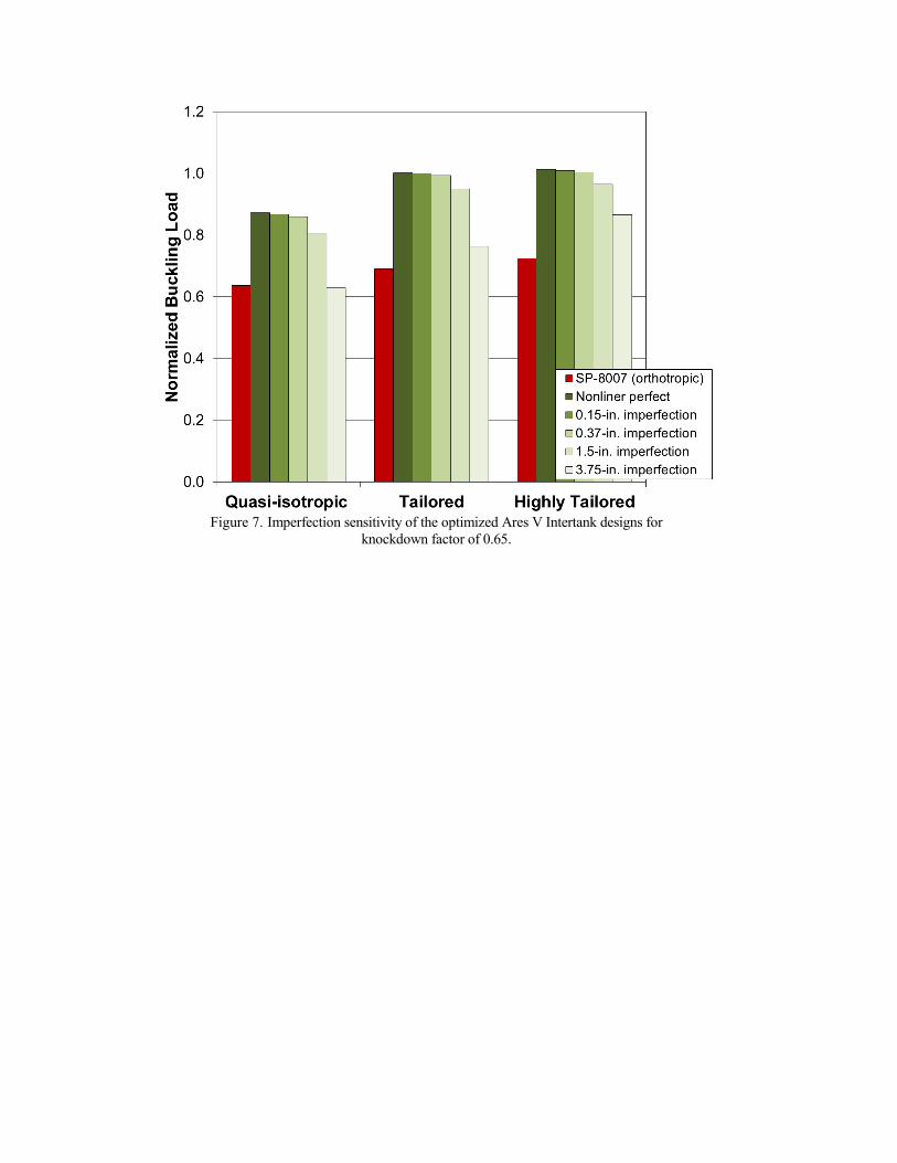
Figure 7. Imperfection sensitivity of the optimized Ares V Intertank designs for
knockdown factor of 0.65.

(a) SLS Skirt
(b) SLS Interstage
Figure 8. Imperfection sensitivity of the optimized (a) SLS Skirt and (b) SLS Interstage designs.