please read all directions before … bmw k1300 s/r installation instructions ... is established you...
TRANSCRIPT

12-004 www.powercommander.com 2009-2014 BMW K1300 S/R - PCV - 1
PARTS LIST
1 PowerCommander1 USBCable1 InstallationGuide2 PowerCommanderDecals2 DynojetDecals2 Velcrostrips1 Alcoholswab
THE LATEST POWER COMMANDER SOFTWARE AND MAP FILES CAN BE
DOWNLOADED FROM OUR WEB SITE AT:www.powercommander.com
2009-2014 BMW K1300 S/R
I ns ta l l a t i on I ns t ruc t i ons
PLEASE READ ALL DIRECTIONS BEFORE STARTING INSTALLATION
THE IGNITION MUST BE TURNED OFF BEFORE INSTALLATION!
2191 Mendenhall Drive North Las Vegas, NV 89081 (800) 992-4993 www.powercommander.com
12-004 www.powercommander.com 2009-2014 BMW K1300 S/R - PCV - 2
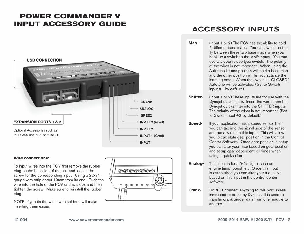
EXPANSION PORTS 1 & 2
OptionalAccessoriessuchasPOD-300unitorAuto-tunekit.
POWER COMMANDER V INPUT ACCESSORY GUIDE
Map - (Input1or2)ThePCVhastheabilitytohold2differentbasemaps.YoucanswitchontheflybetweenthesetwobasemapswhenyouhookupaswitchtotheMAPinputs.Youcanuseanyopen/closetypeswitch.Thepolarityofthewiresisnotimportant.WhenusingtheAutotunekitonepositionwillholdabasemapandtheotherpositionwillletyouactivatethelearningmode.Whentheswitchis“CLOSED”Autotunewillbeactivated.(SettoSwitchInput#1bydefault.)
Shifter- (Input1or2)TheseinputsareforusewiththeDynojetquickshifter.InsertthewiresfromtheDynojetquickshifterintotheSHIFTERinputs.Thepolarityofthewiresisnotimportant.(SettoSwitchInput#2bydefault.)
Speed- Ifyourapplicationhasaspeedsensorthenyoucantapintothesignalsideofthesensorandrunawireintothisinput.ThiswillallowyoutocalculategearpositionintheControlCenterSoftware.Oncegearpositionissetupyoucanalteryourmapbasedongearpositionandsetupgeardependentkilltimeswhenusingaquickshifter.
Analog- Thisinputisfora0-5vsignalsuchasenginetemp,boost,etc.Oncethisinputisestablishedyoucanalteryourfuelcurvebasedonthisinputinthecontrolcentersoftware.
Crank- DoNOTconnectanythingtothisportunlessinstructedtodosobyDynojet.Itisusedtotransfercranktriggerdatafromonemoduletoanother.
ACCESSORY INPUTS
Wire connections:
ToinputwiresintothePCVfirstremovetherubberplugonthebacksideoftheunitandloosenthescrewforthecorrespondinginput.Usinga22-24gaugewirestripabout10mmfromitsend.PushthewireintotheholeofthePCVuntilisstopsandthentightenthescrew.Makesuretoreinstalltherubberplug.
NOTE:Ifyoutinthewireswithsolderitwillmakeinsertingthemeasier.
CRANK
ANALOG
SPEED
INPUT 1 (Grnd)
INPUT 1
INPUT 2 (Grnd)
INPUT 2
USB CONNECTION
12-004 www.powercommander.com 2009-2014 BMW K1300 S/R - PCV - 3
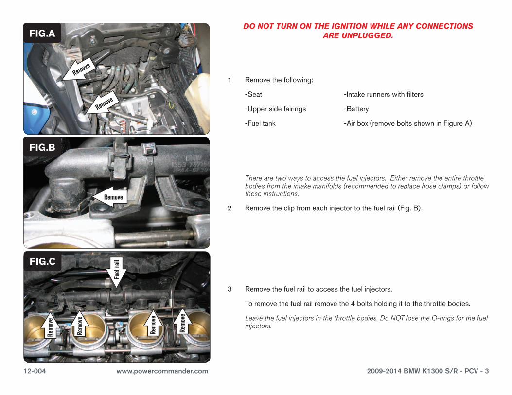
1 Removethefollowing:
-Seat -Intakerunnerswithfilters
-Uppersidefairings -Battery
-Fueltank -Airbox(removeboltsshowninFigureA)
There are two ways to access the fuel injectors. Either remove the entire throttle bodies from the intake manifolds (recommended to replace hose clamps) or follow these instructions.
2 Removetheclipfromeachinjectortothefuelrail(Fig.B).
3 Removethefuelrailtoaccessthefuelinjectors.
Toremovethefuelrailremovethe4boltsholdingittothethrottlebodies.
Leave the fuel injectors in the throttle bodies. Do NOT lose the O-rings for the fuel injectors.
FIG.A
Remove
Ground wire
FIG.B
DO NOT TURN ON THE IGNITION WHILE ANY CONNECTIONS ARE UNPLUGGED.
FIG.C
Fuel
rail
Remove
Remove
Remove
Rem
ove
Rem
ove
Rem
ove
Rem
ove
12-004 www.powercommander.com 2009-2014 BMW K1300 S/R - PCV - 4
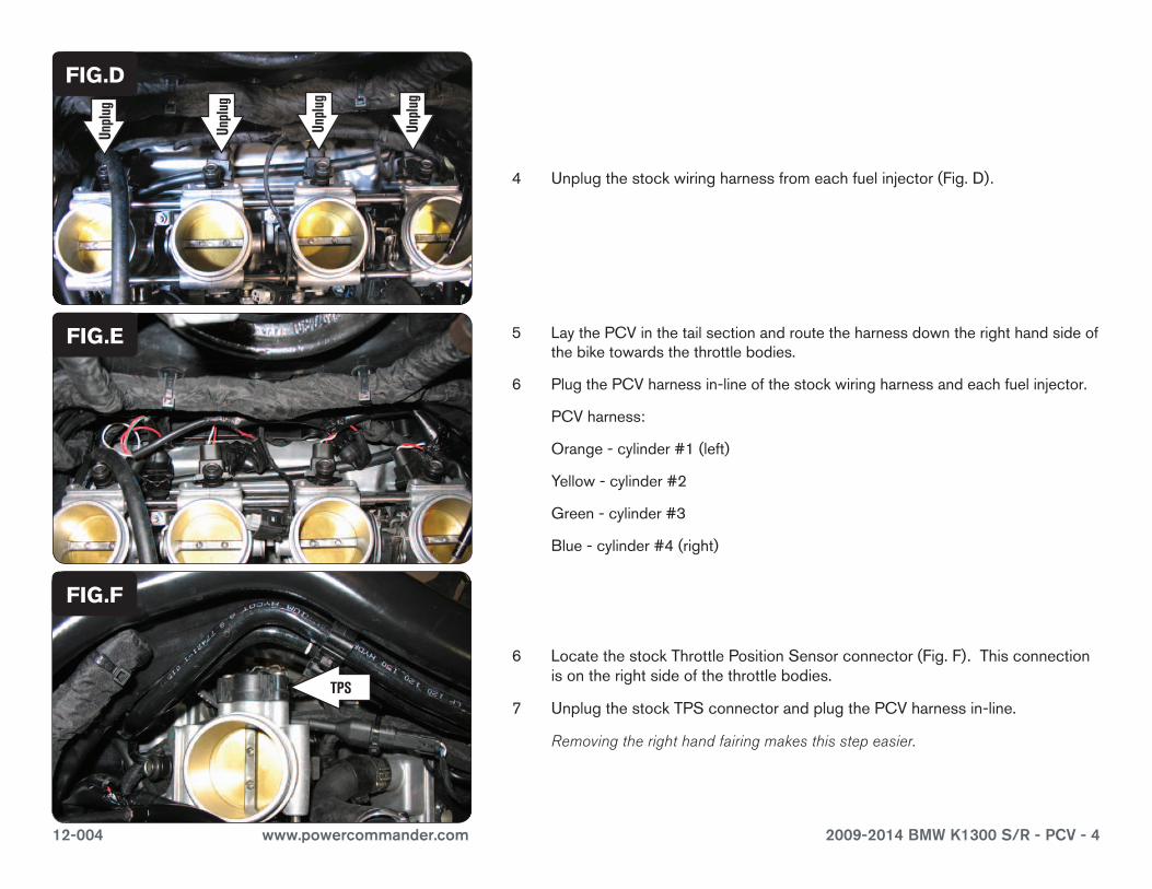
4 Unplugthestockwiringharnessfromeachfuelinjector(Fig.D).
FIG.D
5 LaythePCVinthetailsectionandroutetheharnessdowntherighthandsideofthebiketowardsthethrottlebodies.
6 PlugthePCVharnessin-lineofthestockwiringharnessandeachfuelinjector.
PCVharness:
Orange-cylinder#1(left)
Yellow-cylinder#2
Green-cylinder#3
Blue-cylinder#4(right)
FIG.E
6 LocatethestockThrottlePositionSensorconnector(Fig.F).Thisconnectionisontherightsideofthethrottlebodies.
7 UnplugthestockTPSconnectorandplugthePCVharnessin-line.
Removing the right hand fairing makes this step easier.
FIG.F
Unpl
ug
Unpl
ug
Unpl
ug
Unpl
ug
TPS
12-004 www.powercommander.com 2009-2014 BMW K1300 S/R - PCV - 5
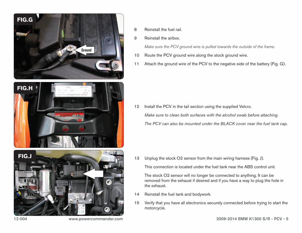
8 Reinstallthefuelrail.
9 Reinstalltheairbox.
Make sure the PCV ground wire is pulled towards the outside of the frame.
10 RoutethePCVgroundwirealongthestockgroundwire.
11 AttachthegroundwireofthePCVtothenegativesideofthebattery(Fig.G).
FIG.G
12 InstallthePCVinthetailsectionusingthesuppliedVelcro.
Makesuretocleanbothsurfaceswiththealcoholswabbeforeattaching.
ThePCVcanalsobemountedundertheBLACKcovernearthefueltankcap.
FIG.H
13 UnplugthestockO2sensorfromthemainwiringharness(Fig.J).
ThisconnectionislocatedunderthefueltankneartheABScontrolunit.
ThestockO2sensorwillnolongerbeconnectedtoanything.Itcanberemovedfromtheexhaustifdesiredandifyouhaveawaytoplugtheholeintheexhaust.
14 Reinstallthefueltankandbodywork.
15 Verifythatyouhaveallelectronicssecurelyconnectedbeforetryingtostartthemotorcycle.
FIG.J
Ground