please read all directions before … before installation! 2191 mendenhall drive north las vegas, nv...
TRANSCRIPT
17-006 www.powercommander.com 2009-2014 Kawasaki VN1700 - PCV - 1
PARTS LIST
1 PowerCommander1 USBCable1 InstallationGuide2 PowerCommanderDecals2 DynojetDecals2 Velcrostrips1 Alcoholswab3 Posi-taps
THE LATEST POWER COMMANDER SOFTWARE AND MAP FILES CAN BE
DOWNLOADED FROM OUR WEB SITE AT:www.powercommander.com
2009-2014 Kawasaki VN1700 Models
I ns ta l l a t i on I ns t ruc t i ons
PLEASE READ ALL DIRECTIONS BEFORE STARTING INSTALLATION
THE IGNITION MUST BE TURNED OFF BEFORE INSTALLATION!
2191 Mendenhall Drive North Las Vegas, NV 89081 (800) 992-4993 www.powercommander.com
CLASSIC - VOYAGER - NOMAD - VAQUERO
17-006 www.powercommander.com 2009-2014 Kawasaki VN1700 - PCV - 2
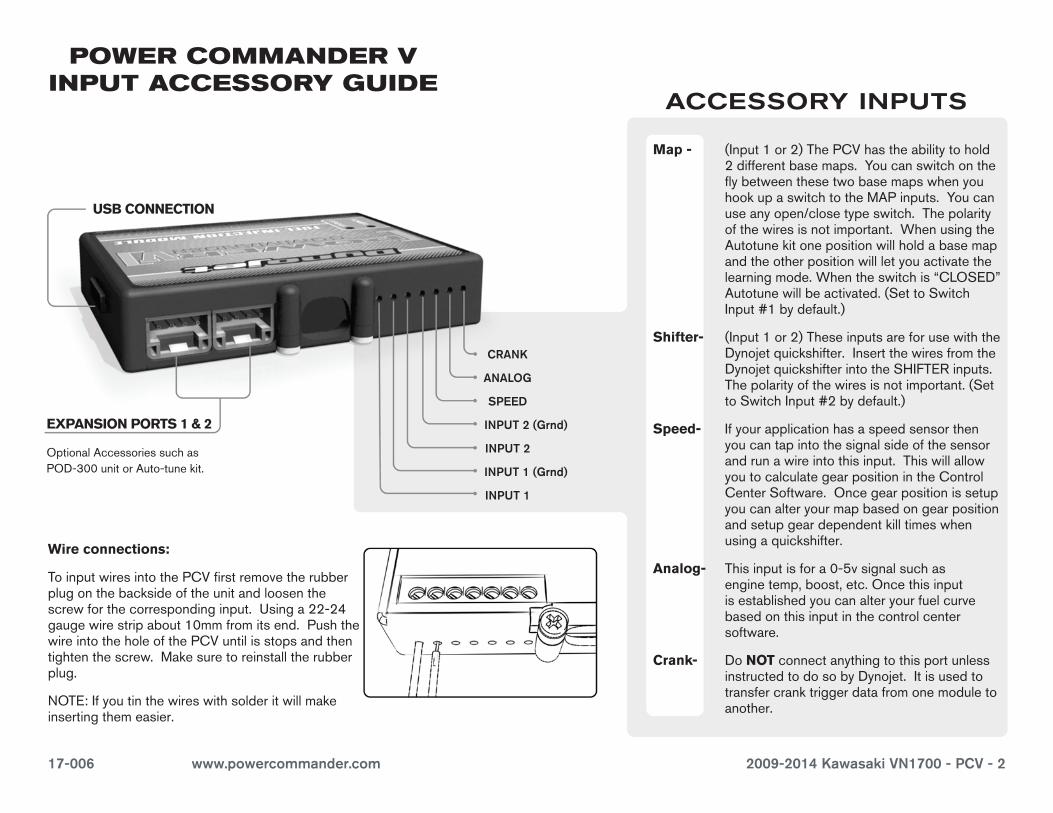
EXPANSION PORTS 1 & 2
OptionalAccessoriessuchasPOD-300unitorAuto-tunekit.
POWER COMMANDER V INPUT ACCESSORY GUIDE
Map - (Input1or2)ThePCVhastheabilitytohold2differentbasemaps.YoucanswitchontheflybetweenthesetwobasemapswhenyouhookupaswitchtotheMAPinputs.Youcanuseanyopen/closetypeswitch.Thepolarityofthewiresisnotimportant.WhenusingtheAutotunekitonepositionwillholdabasemapandtheotherpositionwillletyouactivatethelearningmode.Whentheswitchis“CLOSED”Autotunewillbeactivated.(SettoSwitchInput#1bydefault.)
Shifter- (Input1or2)TheseinputsareforusewiththeDynojetquickshifter.InsertthewiresfromtheDynojetquickshifterintotheSHIFTERinputs.Thepolarityofthewiresisnotimportant.(SettoSwitchInput#2bydefault.)
Speed- Ifyourapplicationhasaspeedsensorthenyoucantapintothesignalsideofthesensorandrunawireintothisinput.ThiswillallowyoutocalculategearpositionintheControlCenterSoftware.Oncegearpositionissetupyoucanalteryourmapbasedongearpositionandsetupgeardependentkilltimeswhenusingaquickshifter.
Analog- Thisinputisfora0-5vsignalsuchasenginetemp,boost,etc.Oncethisinputisestablishedyoucanalteryourfuelcurvebasedonthisinputinthecontrolcentersoftware.
Crank- DoNOTconnectanythingtothisportunlessinstructedtodosobyDynojet.Itisusedtotransfercranktriggerdatafromonemoduletoanother.
ACCESSORY INPUTS
Wire connections:
ToinputwiresintothePCVfirstremovetherubberplugonthebacksideoftheunitandloosenthescrewforthecorrespondinginput.Usinga22-24gaugewirestripabout10mmfromitsend.PushthewireintotheholeofthePCVuntilisstopsandthentightenthescrew.Makesuretoreinstalltherubberplug.
NOTE:Ifyoutinthewireswithsolderitwillmakeinsertingthemeasier.
CRANK
ANALOG
SPEED
INPUT 1 (Grnd)
INPUT 1
INPUT 2 (Grnd)
INPUT 2
USB CONNECTION
17-006 www.powercommander.com 2009-2014 Kawasaki VN1700 - PCV - 3
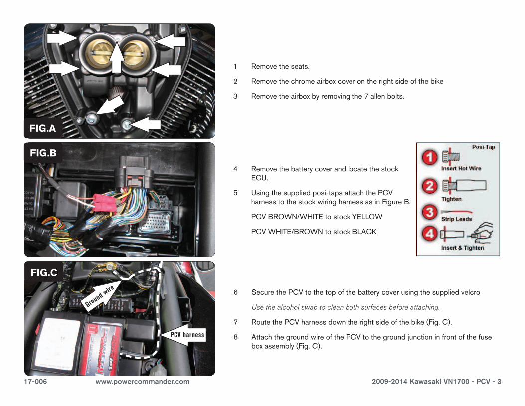
1 Removetheseats.
2 Removethechromeairboxcoverontherightsideofthebike
3 Removetheairboxbyremovingthe7allenbolts.
4 RemovethebatterycoverandlocatethestockECU.
5 Usingthesuppliedposi-tapsattachthePCVharnesstothestockwiringharnessasinFigureB.
PCVBROWN/WHITEtostockYELLOW
PCVWHITE/BROWNtostockBLACK
FIG.C
FIG.B
FIG.A
6 SecurethePCVtothetopofthebatterycoverusingthesuppliedvelcro
Use the alcohol swab to clean both surfaces before attaching.
7 RoutethePCVharnessdowntherightsideofthebike(Fig.C).
8 AttachthegroundwireofthePCVtothegroundjunctioninfrontofthefuseboxassembly(Fig.C).
PCV harness
Ground wire
17-006 www.powercommander.com 2009-2014 Kawasaki VN1700 - PCV - 4
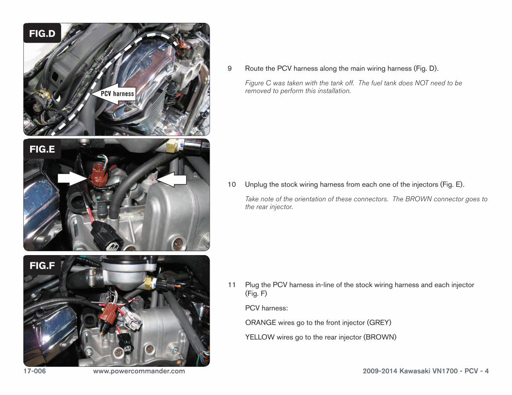
10 Unplugthestockwiringharnessfromeachoneoftheinjectors(Fig.E).
Take note of the orientation of these connectors. The BROWN connector goes to the rear injector.
11 PlugthePCVharnessin-lineofthestockwiringharnessandeachinjector(Fig.F)
PCVharness:
ORANGEwiresgotothefrontinjector(GREY)
YELLOWwiresgototherearinjector(BROWN)
FIG.E
FIG.F
9 RoutethePCVharnessalongthemainwiringharness(Fig.D).
Figure C was taken with the tank off. The fuel tank does NOT need to be removed to perform this installation.PCV harness
FIG.D
17-006 www.powercommander.com 2009-2014 Kawasaki VN1700 - PCV - 5
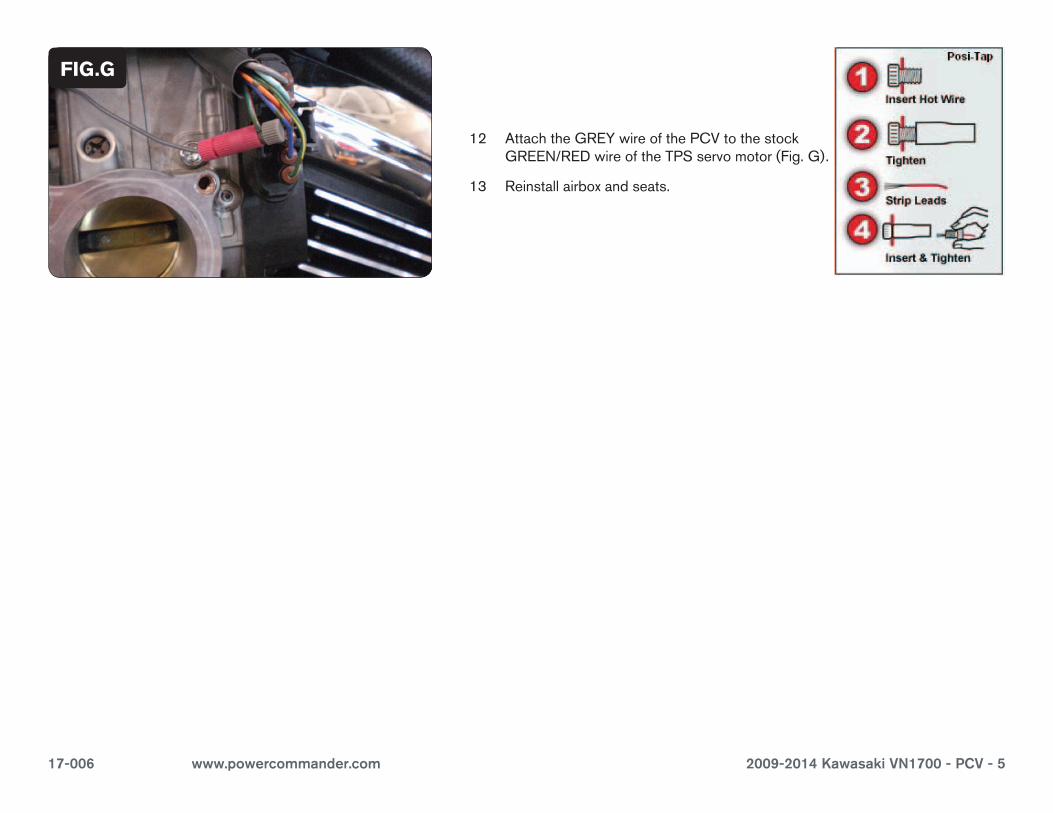
FIG.G
12 AttachtheGREYwireofthePCVtothestockGREEN/REDwireoftheTPSservomotor(Fig.G).
13 Reinstallairboxandseats.