plc-s7-200-em277-manual.pdf
TRANSCRIPT

8/11/2019 plc-s7-200-em277-manual.pdf
http://slidepdf.com/reader/full/plc-s7-200-em277-manualpdf 1/17
S7-200 Specifications
A-50S7-200 Programmable Controller System Manual
A5E00066097-02
A.12 Specifications for the EM 277 PROFIBUS-DP Module
Table A-16 Specifications for the EM 277 PROFIBUS-DP Module
DescriptionOrder Number EM 277 PROFIBUS-DP6ES7 277-0AA20-0XA0
Physical Size
Dimensions (W x H x D)
Weight
Power loss (dissipation)
71 mm x 80 mm x 62 mm
175 g
2.5 W
Communication Features
Number of Ports 1 port
Electrical interface RS-485
Isolation (external signal to PLC logic) 500 VAC (Galvanic)
PROFIBUS-DP/MPI baud rates (set automatically)
Protocols
9.6, 19.2, 45.45, 93.75, 187.5, and 500K baud; 1, 1.5, 3, 6, and12M baud
PROFIBUS-DP slave and MPI slave
Cable Length
Up to 93.75K baud
187.5K baud
500K baud
1 to 1.5M baud
3 to 12M baud
1200 m
1000 m
400 m
200 m
100 m
Network Capabilities
Station address settings
Maximum stations per segment
Maximum stations per network
0 - 99 (set by rotary switches)
32
126, up to 99 EM277 stations
MPI Connections 6 total, 2 reserved (1 for PG and 1 for OP)
Power Consumption
+5 VDC (from I/O bus) 150 mA
24 VDC Input Power Requirements
Voltage range
Maximum currentModule only with port active
Add 90 mA of 5V port load
Add 120 mA of 24V port load
20.4 to 28.8 VDC (Class 2 or sensor power from PLC)
30 mA
60 mA
180 mA
Ripple noise (<10 MHz)1Isolated (input power to module logic)
<1 V peak to peak (maximum)
500 VAC for 1 minute
5 VDC Power on Communication Port
Maximum current per port
Transformer isolation from module
logic and from 24 VDC input power
90 mA
500 VAC for 1 minute
24 VDC Power on Communication Port
Voltage range
Maximum current per port
Current limit
Isolated
20.4 to 28.8 VDC
120 mA
0.7 to 2.4 A
Not isolated, same circuit as input 24 VDC
1 No power is supplied to module logic by the 24 VDC supply. 24 VDC supplies power for the communication port.
http://eyeteck.vn

8/11/2019 plc-s7-200-em277-manual.pdf
http://slidepdf.com/reader/full/plc-s7-200-em277-manualpdf 2/17
S7-200 Specifications
A-51S7-200 Programmable Controller System ManualA5E00066097-02
Compatibility
The EM 277 PROFIBUS-DP slave module is an intelligent expansion moduledesigned to work with the S7-200 PLCs shown in Table A-17.
Table A-17 EM 277 PROFIBUS-DP Module Compatibility with S7-200 PLCs
CPU Description Order Number
CPU 222 DC/DC/DC 6ES7 212-1AB21-0XB0CPU 222 Rel. 1.10 or greater
CPU 222 AC/DC/Relay 6ES7 212-1BB21-0XB0
CPU 224 DC/DC/DC 6ES7 214-1AD21-0XB0CPU 224 Rel. 1.10 or greater
CPU 224 AC/DC/Relay 6ES7 214-1BD21-0XB0
CPU 226 DC/DC/DC 6ES7 216-2AD21-0XB0CPU 226 Rel. 1.00 or greater
CPU 226 AC/DC/Relay 6ES7 216-2BD21-0XB0
Address Switches and LEDs
The address switches and status LEDs are located on the front of the module as
shown in Figure A-26. The EM 277 status LEDs are shown in Table A-20.
M L+
x10
x1
CPU FAULT
POWER
DP ERROR
DX MODE
Address Switches:x10=sets the most significant digit of the addressx1= sets the least significant digit of the address
=Earth ground=24 VDC return=24 VDC
M
L+
Input Power:
DP Slave Port Connector
Figure A-26 Front View of the EM 277 PROFIBUS-DP Module
http://eyeteck.vn

8/11/2019 plc-s7-200-em277-manual.pdf
http://slidepdf.com/reader/full/plc-s7-200-em277-manualpdf 3/17
S7-200 Specifications
A-52S7-200 Programmable Controller System Manual
A5E00066097-02
DP Slave Port Connector
The pin-out for the DP slave port connector is shown in Figure A-27.
5
1
9
6
9-pin D Female Connector Pin # Description
123456789
Chassis ground, tied to the connector shell24V Return (same as M on terminal block)Isolated Signal B (RxD/TxD+)Isolated Request to Send (TTL level)Isolated +5V ReturnIsolated +5V at 90 mA+24V (120 mA maximum, with reverse voltage protection diode)Isolated Signal A (RxD/TxD-)No Connection
9-Pin Sub D Connector Pin-out
Note: Isolated means 500V of isolation from digital logic and 24V input power.
Figure A-27 Pin-out for the DP Slave Port Connector
Distributed Peripheral (DP) Standard Communications
PROFIBUS-DP (or DP Standard) is a remote I/O communication protocol defined
by the European Standard EN 50170. Devices that adhere to this standard are
compatible even though they are manufactured by different companies. DP stands
for distributed peripherals, that is, remote I/O. PROFIBUS stands for Process Field
Bus.
The EM 277 PROFIBUS-DP module has implemented the DP Standard protocol
as defined for slave devices in the following communication protocol standards:
• EN 50 170 (PROFIBUS) describes the bus access and transfer protocol andspecifies the properties of the data transfer medium.
• EN 50 170 (DP Standard) describes the high-speed cyclic exchange of databetween DP masters and DP slaves. This standard defines the procedures forconfiguration and parameter assignment, explains how cyclic data exchangewith distributed I/O functions, and lists the diagnostic options which aresupported.
A DP master is configured to know the addresses, slave device types, and any
parameter assignment information that the slaves require. The master is also told
where to place data that is read from the slaves (inputs) and where to get the data
to write to the slaves (outputs). The DP master establishes the network and then
initializes its DP slave devices. The master writes the parameter assignment
information and I/O configuration to the slave. The master then reads the
diagnostics from the slave to verify that the DP slave accepted the parameters and
the I/O configuration. The master then begins to exchange I/O data with the slave.
Each transaction with the slave writes outputs and reads inputs. The data
exchange mode continues indefinitely. The slave devices can notify the master if
there is an exception condition and the master then reads the diagnostic
information from the slave.
http://eyeteck.vn

8/11/2019 plc-s7-200-em277-manual.pdf
http://slidepdf.com/reader/full/plc-s7-200-em277-manualpdf 4/17
S7-200 Specifications
A-53S7-200 Programmable Controller System ManualA5E00066097-02
Once a DP master has written the parameters and I/O configuration to a DP slave,
and the slave has accepted the parameters and configuration from the master, the
master now owns that slave. The slave only accepts write requests from the
master that owns it. Other masters on the network can read the slave’s inputs and
outputs, but they cannot write anything to the slave.
Using the EM 277 to Connect an S7-200 CPU to the Network as a DP Slave
The S7-200 CPU can be connected to a PROFIBUS-DP network through the
EM 277 PROFIBUS-DP expansion slave module. The EM 277 is connected to the
S7-200 CPU through the serial I/O bus. The PROFIBUS network is connected to
the EM 277 PROFIBUS-DP module through its DP communication port. This port
operates at any PROFIBUS baud rate between 9600 baud and 12 Mbaud. (See
Table A-16 for supported baud rates.) As a DP slave device, the EM 277 module
accepts several different I/O configurations from the master to transfer different
amounts of data to and from the master. This feature allows you to tailor the
amount of data transferred to meet the requirements of the application. Unlikemany DP devices, the EM 277 module does not transfer only I/O data. The
EM 277 moves data to and from a block of variable memory defined in the S7-200
CPU. This allows you to exchange any type of data with the master. Inputs,
counter values, timer values, or other calculated values can be transferred to the
master by first moving the data to the variable memory in the S7-200 CPU.
Likewise, data from the master is stored in variable memory in the S7-200 CPU
and can be moved to other data areas.
The DP port of the EM 277 PROFIBUS-DP module can be attached to a DP
master on the network and still communicate as an MPI slave with other master
devices such as SIMATIC programming devices or S7-300/S7-400 CPUs on the
same network.Figure A-28 shows a PROFIBUS network with a CPU 224 and an EM 277
PROFIBUS-DP module. In this situation, the CPU 315-2 is the DP master and has
been configured by a SIMATIC programming device with STEP 7 programming
software. The CPU 224 is a DP slave owned by the CPU 315-2. The ET 200 I/O
module is also a slave owned by the CPU 315-2. The S7-400 CPU is attached to
the PROFIBUS network and is reading data from the CPU 224 by means of XGET
instructions in the S7-400 CPU user program.
http://eyeteck.vn

8/11/2019 plc-s7-200-em277-manual.pdf
http://slidepdf.com/reader/full/plc-s7-200-em277-manualpdf 5/17
S7-200 Specifications
A-54S7-200 Programmable Controller System Manual
A5E00066097-02
ET 200B
S7-300 withCPU 315-2 DP
SIMATICprogrammingdevice
CPU 400
CPU 224 EM 277 PROFIBUS-DP
Figure A-28 EM 277 PROFIBUS-DP Module and CPU 224 on a PROFIBUS Network
Configuration
To use the EM 277 as a DP slave, you must set the station address of the DP port
to match the address in the configuration of the master. The station address is set
with the rotary switches on the EM 277 module. You must power cycle the CPU
after you have made a switch change in order for the new slave address to take
effect.
The master device exchanges data with each of its slaves by sending information
from its output area to the slave’s output buffer (called a “Receive mailbox”). The
slave responds to the message from the master by returning an input buffer (called
a “Send mailbox”) which the master stores in an input area (see Figure A-29).
The EM 277 can be configured by the DP master to accept output data from the
master and return input data to the master. The output and input data buffers
reside in the variable memory (V memory) of the S7-200 CPU. When you
configure the DP master, you define the byte location in V memory where the
output data buffer should start as part of the parameter assignment information for
the EM 277. You also define the I/O configuration as the amount of output data to
be written to the S7-200 CPU and amount of input data to be returned from the
S7-200 CPU. The EM 277 determines the size of the input and output buffers from
the I/O configuration. The DP master writes the parameter assignment and I/O
configuration information to the EM 277 PROFIBUS DP module. The EM 277 then
transfers the V memory address and input and output data lengths to the S7-200
CPU.
http://eyeteck.vn
8/11/2019 plc-s7-200-em277-manual.pdf
http://slidepdf.com/reader/full/plc-s7-200-em277-manualpdf 6/17
S7-200 Specifications
A-55S7-200 Programmable Controller System ManualA5E00066097-02
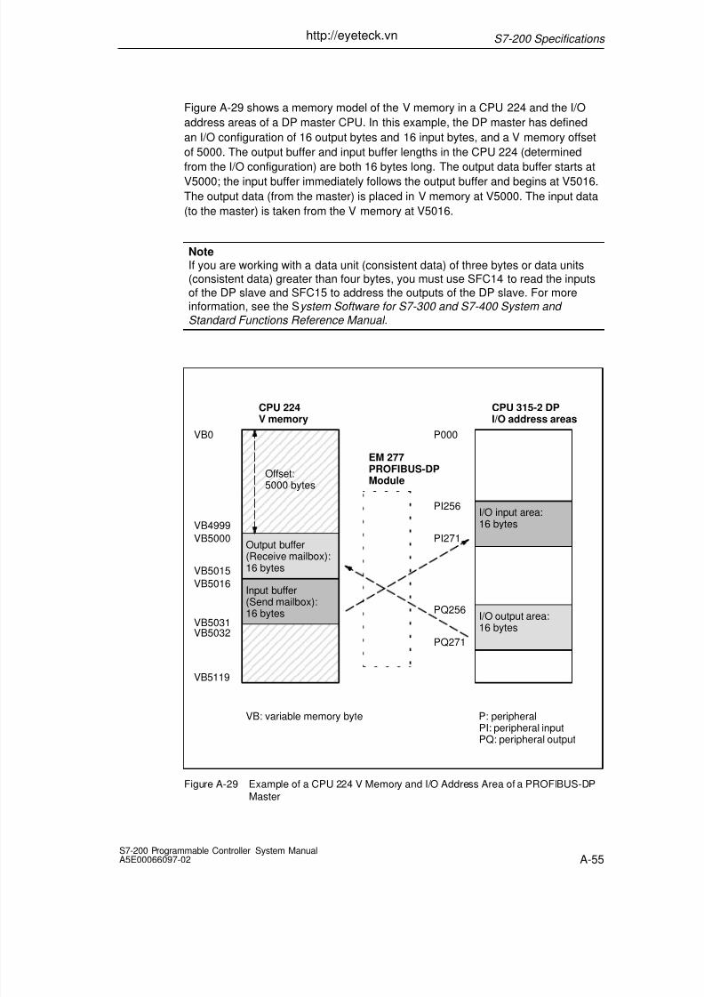
Figure A-29 shows a memory model of the V memory in a CPU 224 and the I/O
address areas of a DP master CPU. In this example, the DP master has defined
an I/O configuration of 16 output bytes and 16 input bytes, and a V memory offset
of 5000. The output buffer and input buffer lengths in the CPU 224 (determined
from the I/O configuration) are both 16 bytes long. The output data buffer starts at
V5000; the input buffer immediately follows the output buffer and begins at V5016.
The output data (from the master) is placed in V memory at V5000. The input data
(to the master) is taken from the V memory at V5016.
NoteIf you are working with a data unit (consistent data) of three bytes or data units(consistent data) greater than four bytes, you must use SFC14 to read the inputs
of the DP slave and SFC15 to address the outputs of the DP slave. For moreinformation, see the System Software for S7-300 and S7-400 System and
Standard Functions Reference Manual .
É É É É É É
É É É É É É
É É É É É É
É É É É É É
É É É É É É
É É É É É É
É É É É É É
É É É É É É
É É É É É É
É É É É É É
É É É É É É
CPU 224V memory
Offset:5000 bytes
Output buffer(Receive mailbox):16 bytes
Input buffer(Send mailbox):16 bytes
CPU 315-2 DPI/O address areas
I/O input area:
16 bytes
I/O output area:16 bytes
VB0
VB5000
VB5015
VB5016
VB5031
VB5119
VB5032
P000
PI256
PI271
PQ256
PQ271
VB: variable memory byte P: peripheralPI: peripheral inputPQ: peripheral output
VB4999
EM 277PROFIBUS-DPModule
Figure A-29 Example of a CPU 224 V Memory and I/O Address Area of a PROFIBUS-DP
Master
http://eyeteck.vn

8/11/2019 plc-s7-200-em277-manual.pdf
http://slidepdf.com/reader/full/plc-s7-200-em277-manualpdf 7/17
S7-200 Specifications
A-56S7-200 Programmable Controller System Manual
A5E00066097-02
Table A-18 list the configurations that are supported by the EM 277 PROFIBUS-DP
module. The default configuration for the EM 277 module is two words of input and
two words of output.
Table A-18 EM 277 Configuration Options
Configuration Inputs to Master Outputs from Master Data Consistency
1 1 word 1 word
2 2 words 2 words
3 4 words 4 words
4 8 words 8 words
5 16 words 16 words
6 32 words 32 words
7 8 words 2 wordsWord Consistency
8 16 words 4 words
9 32 words 8 words
10 2 words 8 words
11 4 words 16 words
12 8 words 32 words
13 2 bytes 2 bytes
14 8 bytes 8 bytes
15 32 bytes 32 bytesByte Consistency
16 64 bytes 64 bytes
17 4 bytes 4 bytes
18 8 bytes 8 bytes
19 12 bytes 12 bytesBuffer Consistency
20 16 bytes 16 bytes
The location of the input and output buffers may be configured to be anywhere in
the V memory of the S7-200 CPU. The default address for the input and output
buffers is VB0. The location of the input and output buffers is part of the parameter
assignment information that the master writes to the S7-200 CPU. The master
must be configured to recognize its slaves and to write the required parameters
and I/O configuration to each of its slaves.
Use the following tools to configure the DP master:
• For SIMATIC S5 masters, use COM PROFIBUS Windows software
• For SIMATIC S7 masters, use STEP 7 programming software
• For SIMATIC 505 masters, use COM PROFIBUS and either TISOFT2 orSoftShop
For detailed information about using these configuration and programming
software packages, refer to the manuals for these devices. For detailed information
about the PROFIBUS network and its components, refer to the ET 200 Distributed
I/O System Manual .
http://eyeteck.vn

8/11/2019 plc-s7-200-em277-manual.pdf
http://slidepdf.com/reader/full/plc-s7-200-em277-manualpdf 8/17
S7-200 Specifications
A-57S7-200 Programmable Controller System ManualA5E00066097-02
Data Consistency
PROFIBUS supports three types of data consistency:
• Byte consistency ensures that bytes are transferred as whole units.
•
Word consistency ensures that word transfers cannot be interrupted by otherprocesses in the CPU. This means that the two bytes composing the word arealways moved together and cannot be split.
• Buffer consistency ensures that the entire buffer of data is transferred as asingle unit, uninterrupted by any other process in the CPU.
Word and buffer consistency force the CPU to halt any other processes, such as
user interrupts, while manipulating or moving the DP I/O data within the CPU.
Word consistency should be used if the data values being transferred are integers.
Buffer consistency should be used if the data values are double words or floating
point values. Buffer consistency should also be used when a group of values all
relate to one calculation or item.
You set the data consistency as part of the I/O configuration in the master. Thedata consistency selection is written to the DP slave as part of the initialization of
the slave. Both the DP master and the DP slave use the data consistency selection
to be sure that data values (bytes, words, or buffers) are transferred uninterrupted
within master and slave. Figure A-30 shows the different types of consistency.
Byte 0
Byte 1
Byte 2
Byte 3
Master Slave
Byte 0
Byte 1
Byte 2
Byte 3
Byte 0
Byte 1
Byte 2
Byte 3
Byte 4
Byte 5
Byte 6
Byte 7
Byte consistency
Word consistency
Buffer consistency
Byte 0
Byte 1
Byte 2
Byte 3
Byte 0
Byte 1
Byte 2
Byte 3
Byte 0
Byte 1
Byte 2
Byte 3
Byte 4
Byte 5
Byte 6
Byte 7
Figure A-30 Byte, Word, and Buffer Data Consistency
http://eyeteck.vn

8/11/2019 plc-s7-200-em277-manual.pdf
http://slidepdf.com/reader/full/plc-s7-200-em277-manualpdf 9/17
S7-200 Specifications
A-58S7-200 Programmable Controller System Manual
A5E00066097-02
User Program Considerations
Once the EM 277 PROFIBUS-DP module has been successfully configured by a
DP master, the EM 277 and the DP master enter data exchange mode. In data
exchange mode, the master writes output data to the EM 277 PROFIBUS-DP
module, the EM 277 module then responds with most current S7-200 CPU inputdata. The EM 277 module continuously updates its inputs from the S7-200 CPU in
order to provide the most recent input data to the DP Master. The module then
transfers the output data to the S7-200 CPU. The output data from the master is
placed into V memory (the output buffer) starting at the address that the DP
master supplied during initialization. The input data to the master is taken from the
V memory locations (the input buffer) immediately following the output data.
The starting address of the data buffers in V memory and the size of the buffers
must be known at the time the user program for the S7-200 CPU is created. The
output data from the master must be moved by the user program in the S7-200
CPU from the output buffer to the data areas where it is to be used. Likewise, the
input data to the master must be moved from the various data areas to the inputbuffer for transfer to the master.
Output data from the DP master is placed into V memory immediately after the
user program portion of the scan has been executed. Input data (to the master) is
copied from V memory to the EM 277 for transfer to the master at this same time.
Output data from the master is only written into V memory when there is new data
available from the master. Input data to the master are transmitted to the master
on the next data exchange with the master.
SMB200 through SMB249 provide status information about the EM 277
PROFIBUS-DP slave module if it is the first intelligent module in the I/O chain. If
the EM 277 is the second intell igent module in the I/O chain, then the EM 277
status is obtained from SMB250 through SMB299. These SM locations showdefault values if DP communication has not been established with a master. After a
master has written parameters and I/O configuration to the EM 277
PROFIBUS-DP module, these SM locations show the configuration set by the DP
master. You should check SMB224 to be sure that the EM 277 is currently in data
exchange mode with the master before using the information in SMB225 through
SMB229 (see Table A-19), or data in the V memory buffer.
NoteYou cannot configure the EM 277 PROFIBUS-DP I/O buffer sizes or buffer
location by writing to memory locations SMB225 through SMB229 or SMB275through SMB279. Only the DP master can configure the EM 277 PROFIBUS-DP
module for DP operation.
http://eyeteck.vn

8/11/2019 plc-s7-200-em277-manual.pdf
http://slidepdf.com/reader/full/plc-s7-200-em277-manualpdf 10/17
S7-200 Specifications
A-59S7-200 Programmable Controller System ManualA5E00066097-02
Table A-19 Special Memory Bytes SMB200 to SMB299
DP is First
Intelligent
Module
DP is Second
Intelligent
Module
Description
SMB200 toSMB215
SMB250 toSMB265
Module name (16 ASCII characters)“EM277 ProfibusDP”
SMB216 to
SMB219
SMB266 to
SMB269
S/W revision number (4 ASCII characters)
xxxx
SMW220 SMW270 Error code
16#0000 No error16#0001 No user power
16#0002 to 16#FFFF Reserved
SMB222 SMB272 DP slave module’s station address as set by address switches (0 - 99decimal)
SMB223 SMB273 Reserved
SMB224 SMB274 DP standard protocol status byte
S1 S0 DP Standard status byte description0 0 DP communication not initiated since power on0 1 Configuration/parameterization error detected1 0 Currently in data exchange mode1 1 Dropped out of data exchange mode
S00 0 0 0 0
MSB LSB
0 S1
SMB225 SMB275 DP standard protocol - address of the slave’s master (0 to 126)
SMW226 SMW276 DP standard protocol - V memory address of the output buffer as an
offset from VB0.SMB228 SMB278 DP standard protocol - number of bytes of output data
SMB229 SMB279 DP standard protocol - number of bytes of input data
SMB230 toSMB249
SMB280 toSMB299
Reserved - cleared on power up
Note: SMB225 to SMB229, and SMB275 to SMB279 are updated each time the DP slave module accepts configuration/
parameterization information. These locations are updated even if a configuration/parameterization error is detected.
The locations are cleared on each power up.
http://eyeteck.vn

8/11/2019 plc-s7-200-em277-manual.pdf
http://slidepdf.com/reader/full/plc-s7-200-em277-manualpdf 11/17
S7-200 Specifications
A-60S7-200 Programmable Controller System Manual
A5E00066097-02
EM 277 PROFIBUS-DP LED Status Indicators
The EM 277 PROFIBUS-DP module has four status LEDs on the front panel to
indicate the operational state of the DP port:
• After the S7-200 CPU is turned on, the DX MODE LED remains off as long asDP communication is not attempted.
• Once DP communication has been successfully initiated (the EM 277PROFIBUS-DP module has entered data exchange mode with the master), theDX MODE LED turns green and remains on until data exchange mode isexited.
• If DP communication is lost, which forces the EM 277 module to exit dataexchange mode, the DX MODE LED turns OFF and the DP ERROR LED turnsred. This condition persists until the S7-200 CPU is powered off or dataexchange is resumed.
• If there is an error in the I/O configuration or parameter information that the DPmaster is writing to the EM 277 module, the DP ERROR LED flashes red.
• If user 24 VDC is not provided, the POWER LED will be off.
Table A-20 summarizes the status indications signified by the EM 277 status LEDs.
Table A-20 EM 277 PROFIBUS-DP Module Status LEDs
LED OFF RED FLASHING RED GREEN
CPU FaultModule is good Internal Module
Failure-- --
POWERNo 24 VDCUser Power
-- -- 24 VDC UserPower Good
DP ERRORNo Error Left Data
Exchange ModeParameterization/ Configuration Error
--
DX MODE
Not in Data
Exchange Mode
-- -- In Data
Exchange Mode
Note When the EM 277 PROFIBUS-DP module is used exclusively as an MPI slave, only the green Power LED is on.
http://eyeteck.vn

8/11/2019 plc-s7-200-em277-manual.pdf
http://slidepdf.com/reader/full/plc-s7-200-em277-manualpdf 12/17
S7-200 Specifications
A-61S7-200 Programmable Controller System ManualA5E00066097-02
Additional Configuration Features
The EM 277 PROFIBUS-DP module can be used as a communication interface to
other MPI masters, whether or not it is being used as a PROFIBUS-DP slave. The
module can provide a connection from the S7-300/400 to the S7-200 using the
XGET/XPUT functions of the S7-300/400. STEP 7-Micro/WIN and a network card(such as the CP5611) using the MPI or PROFIBUS parameter set, an OP device
or the TD 200 (Rel. 2.0 or greater, order number 6ES7 272-0AA20-0YA0) can be
used to communicate with the S7-200 through the EM 277 PROFIBUS-DP
module.
A maximum of six connections (six devices) in addition to the DP master can be
connected to the EM 277 PROFIBUS-DP module. One connection is reserved for
a programming device (PG) and one is reserved for an operator panel (OP). The
other four connections can be used by any MPI master. In order for the EM 277
PROFIBUS-DP module to communicate with multiple masters, all masters must be
operating at the same baud rate. See Figure A-31 for one possible network
configuration.When the EM 277 PROFIBUS-DP module is used for MPI communication, the MPI
master must use the station address of the module for all messages that are sent
to the S7-200 to which the module is connected. MPI messages sent to the EM
277 PROFIBUS-DP module are passed on to the S7-200.
The EM 277 PROFIBUS-DP module is a slave module and cannot be used for
communication between S7-200 PLCs using the NETR and NETW functions. The
EM 277 PROFIBUS-DP module cannot be used for Freeport communication,
which is a feature of the S7-200 communication ports.
Figure A-31 shows the PROFIBUS-DP MPI Network.
MPI MPI
PROFIBUS-DPMPI
PROFIBUS-DP/MPI
PROFIBUS-DPMaster
S7-300XPUTS/XGETS
Functions
PROFIBUS-DP MPI
STEP 7-Micro/WIN1
EM277PROFIBUS-DP
Module
TD 2001,2
S7-22x CPU
1) Communication is possible only tothe S7-200 CPUs and the EM277.
2) TD 200 must be Rel 2.0 or greater.Order number 6ES7 272-0AA20-0YA0.
Figure A-31 PROFIBUS-DP/MPI Network
http://eyeteck.vn

8/11/2019 plc-s7-200-em277-manual.pdf
http://slidepdf.com/reader/full/plc-s7-200-em277-manualpdf 13/17
S7-200 Specifications
A-62S7-200 Programmable Controller System Manual
A5E00066097-02
Device Database File: GSD
Different PROFIBUS devices have different performance characteristics. These
characteristics differ with respect to functionality (for example, the number of I/O
signals and diagnostic messages) or bus parameters such as transmission speed
and time monitoring. These parameters vary for each device type and vendor, andare usually documented in a technical manual. To help you achieve a simple
configuration of PROFIBUS, the performance characteristics of a particular device
are specified in an electronic data sheet called a device database file, or GSD file.
Configuration tools based on GSD files allow simple integration of devices from
different vendors in a single network.
The device database file provides a comprehensive description of the
characteristics of a device in a precisely defined format. These GSD files are
prepared by the vendor for each type of device and made available to the
PROFIBUS user. The GSD file allows the configuration system to read in the
characteristics of a PROFIBUS device and use this information when configuring
the network.The latest versions of the COM PROFIBUS or STEP 7 software include
configuration files for the EM 277 PROFIBUS-DP Module. If your version of
software does not include a configuration file for the EM 277, you can access the
latest GSD file (SIEM089D.GSD) at website www.profibus.com.
If you are using a non-Siemens master device, refer to the documentation provided
by the manufacturer on how to configure the master device by using the GSD file.
Listing of the EM 277 PROFIBUS-DP GSD File
;======================================================
; GSD File for the EM 277 PROFIBUS-DP with a DPC31; MLFB : 6ES7 277-0AA20-0XA0
; DATE : 07-Oct-1999
;======================================================
#Profibus_DP
;General parameters
GSD_Revision = 1
Vendor_Name = ”Siemens”
Model_Name = ”EM 277 PROFIBUS-DP”
Revision = ”V1.00”
Ident_Number = 0x089D
Protocol_Ident = 0
Station_Type = 0
FMS_supp = 0
Hardware_Release = ”1.00”Software_Release = ”1.00”
9.6_supp = 1
19.2_supp = 1
45.45_supp = 1
93.75_supp = 1
187.5_supp = 1
500_supp = 1
1.5M_supp = 1
3M_supp = 1
http://eyeteck.vn

8/11/2019 plc-s7-200-em277-manual.pdf
http://slidepdf.com/reader/full/plc-s7-200-em277-manualpdf 14/17
S7-200 Specifications
A-63S7-200 Programmable Controller System ManualA5E00066097-02
6M_supp = 1
12M_supp = 1
MaxTsdr_9.6 = 60
MaxTsdr_19.2 = 60
MaxTsdr_45.45 = 250
MaxTsdr_93.75 = 60MaxTsdr_187.5 = 60
MaxTsdr_500 = 100
MaxTsdr_1.5M = 150
MaxTsdr_3M = 250
MaxTsdr_6M = 450
MaxTsdr_12M = 800
Redundancy = 0
Repeater_Ctrl_Sig = 2
24V_Pins = 2
; Slave-Specification:
OrderNumber=”6ES7 277-0AA20-0XA0”
Periphery=”SIMATIC S5”
Slave_Family=10@TdF@SIMATIC
Freeze_Mode_supp = 1
Sync_Mode_supp = 1
Set_Slave_Add_Supp = 0
Auto_Baud_supp = 1
Min_Slave_Intervall = 1
Fail_Safe = 0
Max_Diag_Data_Len = 6
Modul_Offset = 0
Modular_Station = 1
Max_Module = 1
Max_Input_len = 128
Max_Output_len = 128
Max_Data_len = 256
; UserPrmData-Definition
ExtUserPrmData=1 ”I/O Offset in the V-memory”
Unsigned16 0 0-5119
EndExtUserPrmData
; UserPrmData: Length and Preset:
User_Prm_Data_Len=3
User_Prm_Data= 0,0,0
Max_User_Prm_Data_Len=3
Ext_User_Prm_Data_Const(0)=0x00,0x00,0x00
Ext_User_Prm_Data_Ref(1)=1
; Module Definition List
Module = ”2 Bytes Out/ 2 Bytes In -” 0x31
EndModule
Module = ”8 Bytes Out/ 8 Bytes In -” 0x37
EndModule
Module = ”32 Bytes Out/ 32 Bytes In -” 0xC0,0x1F,0x1F
EndModule
Module = ”64 Bytes Out/ 64 Bytes In -” 0xC0,0x3F,0x3F
EndModule
Module = ”1 Word Out/ 1 Word In -” 0x70
EndModule
Module = ”2 Word Out/ 2 Word In -” 0x71
EndModule
http://eyeteck.vn

8/11/2019 plc-s7-200-em277-manual.pdf
http://slidepdf.com/reader/full/plc-s7-200-em277-manualpdf 15/17
S7-200 Specifications
A-64S7-200 Programmable Controller System Manual
A5E00066097-02
Module = ”4 Word Out/ 4 Word In -” 0x73
EndModule
Module = ”8 Word Out/ 8 Word In -” 0x77
EndModule
Module = ”16 Word Out/ 16 Word In -” 0x7F
EndModuleModule = ”32 Word Out/ 32 Word In -” 0xC0,0x5F,0x5F
EndModule
Module = ”2 Word Out/ 8 Word In -” 0xC0,0x41,0x47
EndModule
Module = ”4 Word Out/ 16 Word In -” 0xC0,0x43,0x4F
EndModule
Module = ”8 Word Out/ 32 Word In -” 0xC0,0x47,0x5F
EndModule
Module = ”8 Word Out/ 2 Word In -” 0xC0,0x47,0x41
EndModule
Module = ”16 Word Out/ 4 Word In -” 0xC0,0x4F,0x43
EndModule
Module = ”32 Word Out/ 8 Word In -” 0xC0,0x5F,0x47
EndModuleModule = ”4 Byte buffer I/O -” 0xB3
EndModule
Module = ”8 Byte buffer I/O -” 0xB7
EndModule
Module = ”12 Byte buffer I/O -” 0xBB
EndModule
Module = ”16 Byte buffer I/O -” 0xBF
EndModule
Sample Program for DP Communication to a CPU 224
A sample program in Statement List for a CPU 224 that uses the DP port
information in SM memory is shown in Figure A-32. Figure A-33 shows the sameprogram in ladder logic. This program determines the location of the DP buffers
from SMW226 and the sizes of the buffers from SMB228 and SMB229. This
information is used in the program the copy the data in the DP output buffer to the
process-image output register of the CPU 224. Similarly, the data in the
process-image input register of the CPU 224 are copied into the V memory input
buffer.
http://eyeteck.vn

8/11/2019 plc-s7-200-em277-manual.pdf
http://slidepdf.com/reader/full/plc-s7-200-em277-manualpdf 16/17
S7-200 Specifications
A-65S7-200 Programmable Controller System ManualA5E00066097-02
// Sample DP program
// The DP configuration data in the SM memory area provides the
// configuration of the DP slave. The program uses the
// following data:
//// SMW220 DP Module Error Status
// SMB224 DP STATUS
// SMB225 Master Address
// SMW226 V memory offset of outputs
// SMB228 Number of bytes of output data
// SMB229 Number of bytes of input data
// VD1000 Output Data Pointer
// VD1004 Input Data Pointer
//
NETWORK 1
//
// Calculate the Output data pointer into V memory.
//
LDB= SMB224, 2 // if ( in data exchange mode )MOVD &VB0, VD1000 // Output buffer is an offset from VB0.
ITD SMW226, AC0 // Add Vmem offset to get output
+D AC0, VD1000 // buffer offset
NETWORK 2
//
// Calculate the Input data pointer into V memory.
//
LDB= SMB224, 2 // if ( in data exchange mode )
MOVD VD1000, VD1004 // Get the output pointer address
BTI SMB228, AC0 // Add the number of output bytes
ITD AC0, AC0 // to the output pointer to get
+D AC0, VD1004 // the starting input pointer.
NETWORK 3
//
// Set amount of data to be copied.
//
LDB= SMB224, 2 // if ( in data exchange mode )
MOVB SMB228, VB1008 // Get number of output bytes to copy
MOVB SMB229, VB1009 // Get number of input bytes to copy
NETWORK 4
//
// Transfer Masters Outputs to CPU’s Outputs. Copy CPU’s inputs
// to the Master’s inputs.
//
LDB= SMB224, 2 // if ( in data exchange mode )
BMB *VD1000, QB0, VB1008 // Copy master outputs to CPU outputs
BMB IB0, *VD1004, VB1009 // Copy CPU inputs to Master’s Inputs
Figure A-32 STL Sample Program for DP Communication to a CPU 224
http://eyeteck.vn

8/11/2019 plc-s7-200-em277-manual.pdf
http://slidepdf.com/reader/full/plc-s7-200-em277-manualpdf 17/17
S7-200 Specifications
A-66S7-200 Programmable Controller System Manual
A5E00066097-02
SMB224
Network 1
IN&VB0
MOV_DW
OUT VD1000
EN ENO
Calculate the output data pointer into V memory.
==B
2
INSMW226
I_DI
OUT AC0
EN ENO
OUT
ADD_DI
EN
IN1
IN2
OUT AC0
VD1000
AC
ENO
VD1000
SMB224
Network 2
IN VD1000
MOV_DW
OUT VD1004
EN ENO
Calculate the input data pointer into V Memory.
==B
2
INSMB228
B_I
OUT AC0
EN ENO
OUT
ADD_DI
EN
IN1
IN2
OUT AC0
VD1004
ENO
VD1004
IN ACO
I_DI
OUT AC0
EN ENO
SMB224
Network 3
Set amount of data to be copied.
==B
2 INSMB228
MOV_B
OUT VB1008
EN ENO
INSMB229
MOV_B
OUT VB1009
EN ENO
SMB224
Transfer Master Outputs to CPU Outputs. Copy CPU inputs to the Master inputs.
==B
2
OUT
BLKMO~1
EN
IN
N
OUT*VD1000
VB1008
ENO
QB0
OUT
BLKMO~1
EN
IN
N
OUTIB0
VB1009
ENO
*VD1004
Network 4
Figure A-33 LAD Sample Program for DP Communication to a CPU 224
http://eyeteck.vn