plc-programmingbwo-elektronik.de/.../bwo_programmierung_plc_gb.pdf · 2014-12-04 ·...
TRANSCRIPT

PLC-Programming
1 Introduction
2 Starting system
3 Files
4 Editor assembler
5 Editor logic
6 Editor ladder
7 Editor State Machines
8 Editor BWONET
9 Menu PI
10 Run
11 List
12 Define
13 Options
CONTROL SYSTEM 900

Edition 02.2004 1 - 1
PLC900 INTRODUCTION
1. Introduction
1.1 Installation of the system 1 - 5
1.2 Files of the programming system 1 - 7
1.3 Individual configuration of the system 1 -10
⌧

1 - 2 Edition 02.2004
PLC900 INTRODUCTION
1. Introduction for the programming system
The PLC900 programming system consists of the following programs:
PLC900.EXE ‘Real mode’ version of the PLC900 software
PLC900X.EXE ‘Protected mode’ version of the PLC900 software
FBE.EXE Function module editor
FUB.EXE Function module editor
PLCCONV.EXE Conversion program for printer files

Edition 02.2004 1 - 3
PLC900 INTRODUCTION
1. Introduction for the programming system (continued)
Explanations
‘Real mode’
The processors of the series i8086 and i80186 work in the operation mode ‘real mode’. For rea-sons of compatibility, this operation mode is supported by the whole of the processors of thefamily i80x86 being in use today, too.
The main feature of this operation mode is the memory addressing. Processors of the seriesi8086 and i80186 form the memory addresses of the working storage out of two address sections(segment address / offset address) of 16 bits which are composed in one address of 20 bits.Thereby, a maximum of 1 MB can be addressed.
Example for the storage occupancy of an i8086 / i80186 computer:
Computers of the series i8086 and i80186 make available a maximum of 580kB resp. 600kB ofmemory for the programs. The programming system PLC900.EXE has been adapted to thisrequirement and can, therefore, be operated on all of the IBM-compatible computers having amemory of 1MB.
0
1MB
640kB
High memory area
384kB
partly occupied bysystem hardware(graphic adapter etc.)
Conventional memory
640kB
free for MS-DOS programs
appr. 580kB
occupied by MS-DOS

1 - 4 Edition 02.2004
PLC900 INTRODUCTION
1. Introduction for the programming system (continued)
‘Protected mode’
Processors of the series i80286 and higher support the operation mode ‘Protected mode’ whichenables to address more than 1MB of memory.
The memory is hereby addressed by an 24bit address which is formed out of two address sec-tions (segment address / offset address) of a width of 16bit. By this means, an address range of16MB is addressable. With this operation mode, it is possible to hold several programs in thememory at the same time without one program overwriting memory areas of the other anddestroying them by doing so (multitasking application).
Example for the storage occupancy of an i80486 computer:
The programming system PLC900X.EXE supports the ‘protected mode’ and can make availablemore memory for symbols, state machines and ladders/logics.
0
1MB
640kB
4MB
Add-on memory
3MB
free for MS-DOS programs
High memory area
384kB
partly occupied bysystem hardware(graphic adapter etc.)
Conventional memory
640kB
free for MS-DOS programs
appr. 580kB
occupied by MS-DOS
The ‘protected mode’ requiresMS-DOS applications that supportespecially this operation mode aswell as the drive programsDPMI16BI.OVL and RTM.EXE.

Edition 02.2004 1 - 5
PLC900 INTRODUCTION
1.1 Installation of the system
For installing the PLC900 programming system, you start the installing program INSTALL from yourPLC900 installations disk. Put the disk in drive A: or B:.
Key in the commands A: or B:INSTALL INSTALL
and press the enter key.
The installing program creates all of the necessary directories on your hard disk, unpacks the wholeof the PLC900 system files and reproduces them on the hard disk.
The installing program creates on your hard disk the following directories:
\PLC900 Main directory: Contains all of the executable PLC900 programs.
\PLC900\LIB Library directory: Contains all of the PLC900 program libraries.
\PLC900\PRINT Printing directory: Contains all of the printing files created by PLC900.
\PLC900\SCRATCH Buffer directory: Contains the buffer files of the PLC900 system.
1 - 6 Edition 02.2004
PLC900 INTRODUCTION
1.1 Installation of the system (continued)
After having installed the PLC900 system on your computer successfully, the following amend-ments still have to be added to your system files AUTOEXEC.BAT and CONFIG.SYS.
AUTOEXEC.BAT : PATH = [path] [LW] : \PLC900
[path] Previous search path.[LW] Hard disk drive on which the PLC900 has been installed.
CONFIG.SYS : FILES = 30The command FILES = 30 predefines a minimum requirement.If there was previously registered in your system e.g. FILES = 60, thisamendment is not necessary.
DEVICE = EMM386.EXEDelete the driver EMM386.EXE and comment it with REM. The driver canlead to system crashes in connection with the PLC900.
Notice: The library directory, printing directory and buffer directory may be renamed. Whendoing so it is, however, required to indicate the new names of the directories in the PLC900configuration (also see ‘ Individual configuration of the system’). The main directory must not berenamed since the PLC900 software can only be run in the directory \PLC900.

Edition 02.2004 1 - 7
PLC900 INTRODUCTION
1.2 Files of the programming system
In the directory \PLC900 there are the following system files:
PLC900.EXE ‘Real mode’ version of the PLC900 softwarePLC900X.EXE ‘Protected mode’ version of the PLC900 softwareFBE.EXE Function module editor for IBM-compatible computersFUB.EXE Function module editor for microcomputers MT IV/MT VIPLCCONV.EXE Conversion program for printing files
PLC900.CFG Configuration file for PLC900PATH.PLC System file for buffering the working directoryMNEMO System file for PLC programmingCODSIZE System file for PLC programmingSKETTE System file for programming state machines (PLC900 versions 1.0 ,2.01)SKETTE2 System file for programming state machines (PLC900 version 2.1 and higher)PICA.BIN Additional character set for process picturesNET.CFG BWONET configuration file
MENUES.* System file for menutexts being specific for individual countriesDHELP*.* On-line help files in GermanERRORMSG.HD On-line help file for error messages in GermanHELP*:* On-line help files in EnglishERRORMSG.H On-line help file for error messages in English
PLC900.OVR Overlay file for PLC900.EXEDPMI16BI.OVL System file for supporting the protected modeRTM.EXE System file for supporting the protected modePLC900.ICO Program icon for PLC900.EXE and PLC900X.EXE under Windows 3.xFBE.ICO Program icon for FBE.EXE under Windows 3.x
1 - 8 Edition 02.2004
PLC900 INTRODUCTION
1.2 Files of the programming system (continued)
In the directory \PLC900\LIB there are the following files:
LIB900.LNK BWO standard library for the PLC900
LIB.* Library files for function modulesALLOC.* Library files for administrating the dynamic random access memoryHEAP.* Library files for administrating the dynamic random access memory
and flag definitionsSTEP.* Library files for state machinesTIMDEF1.* Library files for timer definitionMERKER.* Library files for defining and initializing the customer’s specific flag range
FUPLIB.* Library files for networksGOBACK.* Library files for watchdog administration*.FUB Function module files
FUBLIST.* Country-specific on-line help for selecting function modules*.H On-line help for function modules (English)*.HD On-line help for function modules (German)
In the directory \PLC900\SCRATCH there are the following files:
*.$$$ Buffer files for the PLC900 systemPLC900.TGR Trigger conditions for the logic-status recorder

Edition 02.2004 1 - 9
PLC900 INTRODUCTION
1.2 Files of the programming system (continued)
The PLC900 programming system processes the following files:
*.COD Program code*.CKS Program proof total*.TIT Program comments*.LBL Labels*.LBT Labels*.LC Line comments*.LCT Line comments*.CMT Symbol definitions*.ASF I/O definitions*.DEL Help file for I/O definitions*.NET BWONET configuration*.OBJ HKC50 program*.SCR Script command file*.LNK Link file*.CFG System configuration*.OPT Printing options*.NWL Printing options*.PRN Printing file*.PHD Program documentation*.HDR Heading line of the program printout*.BOT Bottom line of the program printout*.TRG Trigger conditions for the PLC900 logic analyzer*.DIB Data for process picture*.DIL Data for process picture*.PLC System file for fast program start*.NW ASCII file of a network*.SM ASCII file of a state machine*.$$$ Buffer files
1 - 10 Edition 02.2004
PLC900 INTRODUCTION
1.3 Individual configuration of the system
The PLC900 programming software allows the user to vary certain basic settings of the softwareaccording to his own requirements. The configuration file PLC900.CFG, which is located in thedirectory \PLC900, serves this purpose. PLC900.CFG is a text file that can be processed bymeans of every DOS editor.In the text file there are contained certain keywords and parameters which are converted uponstarting the program. The configuration option has to have the following form:
[keyword] : [parameter]
By adding the appropriate keyword or varying one parameter, the configuration can be altered.The alterations become effective only upon starting the PLC900 software anew. If there a con-figuration option is not available, presettings are made by the PLC900 system.
Keyword Parameter Signification
PLC900YN
Operation mode of the PLC900 softwarePLC900 programming systemThe PLC500 programming system is emulated.Presetting: Y
PC_TYPEIBMIBMEM
IBMH
SIEMENSHK
Type of the utilized programming device:IBM-compatible computerIBM-compatible computer with EGA monochromescreenIBM-compatible computer with Hercules graphicboardSiemens programming device PG 685Microcomputer MTIV / MTVIPresetting: IBM
COM1COM2COM3COM4
Used interface of the programming devicePresetting: COM1
LANGUAGEDGB
Country-specific language identificationGermanEnglishPresetting: GB

Edition 02.2004 1 - 11
PLC900 INTRODUCTION
1.3 Individual configuration of the system (continued)
Keyword Parameter Signification
IO_DEF Country-specific input and output symbolsEA GermanIO English
Presetting: EA
SCRATCH_DIR [path] Directory for PLC900 buffer filesPresetting: [path]=C:\PLC900\SCRATCH
FUB_DIR [path] Directory for PLC900 librariesPresetting: [path]=C:\PLC900\SCRATCH
PRINT_DIR [path] Directory for PLC900 printing filesPresetting: [path]=C:\PLC900\PRINT
STATION_SELECT Activate the inquiry for the BWONET stationnumber upon starting PLC900.Presetting: deactivated
QUICK_START Y Activate fast program start in on-line operationmode
N Deactivate fast program startPresetting: Y
DUP_SYMBOLS Y Using double symbol names is preventedN Using double symbol names is enabled
Presetting: Y
LOGIC_TYP Presetting for network editorLADDER Preset ladderLOGIC Preset logic
Presetting: LADDER
MENUE_COLOR [HGVG] Setting of colours for menus (see comments)Presetting: [HGVG]=$17
WORK_COLOR [HGVG] Setting of colours for editors (see comments)Presetting: [HGVG]=$70
WORK1_COLOR [HGVG] Setting of colours for function windows(see comments)Presetting: [HGVG]=$30

1 - 12 Edition 02.2004
PLC900 INTRODUCTION
1.3 Individual configuration of the system (continued)
Keyword Parameter Signification
CURSOR_COLOR [HGVG] Setting of colours for the selection bar(see comments)Presetting: [HGVG]=$3F
EDIT_CURSOR_COLOR [HGVG] Setting of colours for the cursor(see comments)Presetting: [HGVG]=$1F
MAXTICKX [n] Mouse sensitivity in horizontal direction(see comments)Presetting: [n]=50
MAXTICKY [n] Mouse sensitivity in vertical direction(see comments)Presetting: [n]=50
ROLL Behaviour of the selection bar when arriving at thelast menu or function name.
Y Scrolling the menusN Not scrolling the menus
Presetting: Y
VIDEO_TIME [n] Darkening the screen after [n] seconds(Screen protector)Presetting: [n]=0 (no screen protector)
CURON [n] Predefine the cursor symbol for the PLC900 uponthe cursor being switched on (see comments)Presetting: [n]=$010D
CUROFF [n] Predefine the cursor symbol for the PLC900 uponthe cursor being switched off (see comments)Presetting: [n]=$1310
SKIP_TYPE Correction of the SH and SL command uponinserting program lines.
0 The branch distance is not corrected when thecursor is placed on the target address of the SH/SLcommand and an inserting operation is executed.
1 The branch distance is not corrected.Presetting: 0

Edition 02.2004 1 - 13
PLC900 INTRODUCTION
1.3 Individual configuration of the system (continued)
Keyword Parameter Signification
CLOCK_SYM [flag] Starting address of a flag block with 8 flags.Starting with [flag], the real time clock of the centralunit is filed on this area(see comments).Presetting: [flag] = no
KOP_ONLY Blocking instruction list and logicY Picturing networks only in the ladderN Picturing networks in the instruction list, ladder and
logic.Presetting: N
KEY_LOCK Blocking the process picture representationY Escaping from the process picture is not possible
by pressing <ESC>N Escaping from the process picture is possible by
pressing <ESC>Presetting: N
PRINT_INIT [s] Control character for initializing the connectedprinter (see comments)Presetting:[s]=^[ + ^O
MODEM Y Modem is connected to the programming interfaceN There is no modem connected
Presetting: N
MODINI [s] Character string for initializing the connectedmodem (see comments)Presetting: [s] = none
DIAL [s] Prefix string for dialling(see comments)Presetting: [s] = ’ATD’
HANGUP [s] Prefix string for the modem hanging up(see comments)Presetting: [s] 0 ’ATH0'

1 - 14 Edition 02.2004
PLC900 INTRODUCTION
1.3 Individual configuration of the system (continued)
Keyword Parameter Signification
ZPL_TYPE Type of the central unit ZPL(only for operation mode PLC500)
4K ZPL with 4K memory16K ZPL with 16K memory
Presetting: 16K
I_BASE [n] Base address for the memory areaof the inputs. Allows to relocate theinput picture in the memory.(Only for the operation mode PLC500)Presetting: [n]=$F000
MUXER_CH [n] Setting the channel number for the serial interfaceof the microcomputers MTIV / MTVIPresetting: [n]=1
BAUDRATE [n] Setting the data transmission rate of the serialinterface.Presetting: [n]=9600
MT7080 Setting the number of function keys that issupported by the process picture.
Y 5 function keys (for MT70, MT75, MT80)N 6 function keys (standard)
Presetting: N
Edition 02.2004 1 - 15
PLC900 INTRODUCTION
1.3 Individual configuration of the system (continued)
Comments
Setting the colours
The used screen colours are composed of the foreground colour (FG) and the background colour(BG). FG and BG are stored in an 8bit number.With it there is constituted by
bit 0...bit 2 the foreground colourbit 4...bit 6 the background colourbit 3 defines the intense colour modebit 7 defines the flashing mode
Example: In order to represent on the screen white characters on a green background, youenter the sedecimal number $2F, $2 being the colour code for green and $F thecolour code for white.
By means of the colour code table, all colour combinations can be set.
Colour code table
Black $0Blue $1Green $2Turquoise $3Red $4Fuchsine red $5Brown $6Light grey $7Dark-grey $8Light blue $9Light green $ALight turquoise $BLight red $CLight fuchsine red $DYellow $EWhite $F
1 - 16 Edition 02.2004
PLC900 INTRODUCTION
1.3 Individual configuration of the system (continued)
Mouse sensitivity
By the value [n] it is possible to affect the sensitivity of the mouse in horizontal and in verticaldirection separately from each other. There is applied
[n]=50 normal sensitivity[n]<50 inferior sensitivity (mouse is faster)[n]>50 higher sensitivity (mouse is slower)
The suitable setting can be found by means of experimental values.
Cursor symbols
Setting the shape of the cursor is usually not required. As to certain graphic boards it may, how-ever, occur that the cursor is not switched on resp. off correctly within the PLC900. Should thiscase arise, the cursor has to be adapted.This is performed by entering a 16bit number. The bits 0...7 of the number indicate the stop line ofthe cursor, the bits 8...15 indicate the start line of the cursor. Between the start and the stop line,the cursor appears as flashing horizontal stroke. By entering different values for the start line andthe stop line, the width of the cursor stroke can be varied. By entering start and stop values beinggreater than 16 or those that are invalid, the cursor can be blinded out.
Example 1: In order to let appear the cursor above the current screen character, the value ofthe 16bit number has to be $010D, consequently start line $01, stop line $0D.
Example 2: In order to let disappear the cursor, the value of the 16bit number may be $1010,consequently start line and stop line $10.

Edition 02.2004 1 - 17
PLC900 INTRODUCTION
1.3 Individual configuration of the system (continued)
Real time clock
The current values of the real time clock are filed as follows:
Address value
[flag] year[flag]+1 month[flag]+2 day[flag]+3 day of the week[flag]+4 hour[flag)+5 minute[flag)+6 second[flag)+7 hundredth-second
Initializing the modem
Modifying the modem initializer is usually not required. As to certain modems it is, however,necessary to perform a special initialization. Please read the description of your modem for fur-ther details.
Prefix strings for the modem dialling / hanging up
Modifying the prefix strings is usually not required. As to certain modems it is, however, necessaryto use special prefix strings. Please read the description of your modem for further details.
Initializing the printer
Modifying the printer initializer is usually not required. As to certain printers it may, however, occurthat the instruction sequences are not accepted so that e.g. setting for condensed font (137characters per line) or the instruction for making up the page is not performed. Should this casearise, information on the required instruction sequence for your printer is available.
1 - 18 Edition 02.2004
PLC900 INTRODUCTION
1.3 Individual configuration of the system (continued)
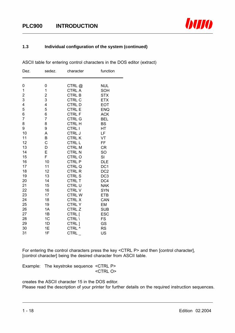
ASCII table for entering control characters in the DOS editor (extract)
For entering the control characters press the key <CTRL P> and then [control character],[control character] being the desired character from ASCII table.
Example: The keystroke sequence <CTRL P><CTRL O>
creates the ASCII character 15 in the DOS editor.Please read the description of your printer for further details on the required instruction sequences.
Dez. sedez. character function
012345678910111213141516171819202122232425262728293031
0123456789ABCDEF101112131415161718191A1B1C1D1E1F
CTRL @CTRL ACTRL BCTRL CCTRL DCTRL ECTRL FCTRL GCTRL HCTRL ICTRL JCTRL KCTRL LCTRL MCTRL NCTRL OCTRL PCTRL QCTRL RCTRL SCTRL TCTRL UCTRL VCTRL WCTRL XCTRL YCTRL ZCTRL [CTRL \CTRL ]CTRL ^CTRL _
NULSOHSTXETXEOTENQACKBELBSHTLFVTFFCRSOSIDLEDC1DC2DC3DC4NAKSYNETBCANEMSUBESCFSGSRSUS
Edition 02.2004 2 - 1
PLC900 STARTING SYSTEM
2. Introduction for the programming system
2.4 Starting the system 2 - 2
2.5 Menu system 2 -10
2.6 Main menu 2 -13
⌧
2 - 2 Edition 02.2004
PLC900 STARTING SYSTEM
2.1 Starting the system
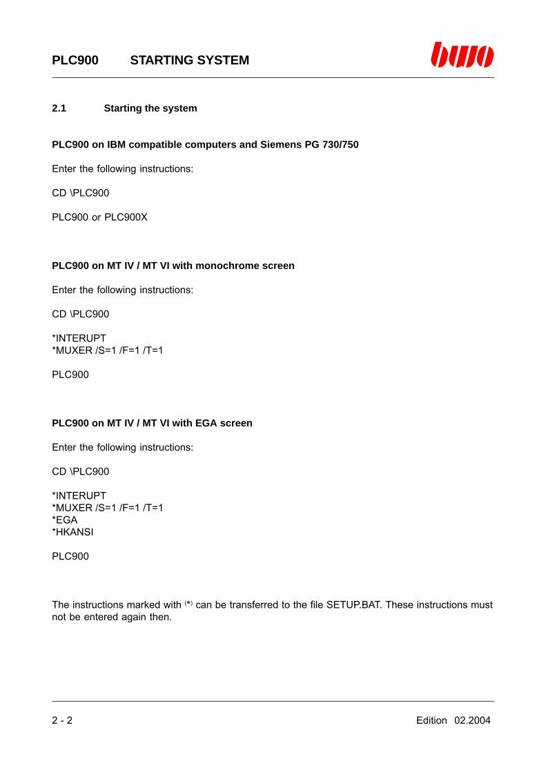
PLC900 on IBM compatible computers and Siemens PG 730/750
Enter the following instructions:
CD \PLC900
PLC900 or PLC900X
PLC900 on MT IV / MT VI with monochrome screen
Enter the following instructions:
CD \PLC900
*INTERUPT*MUXER /S=1 /F=1 /T=1
PLC900
PLC900 on MT IV / MT VI with EGA screen
Enter the following instructions:
CD \PLC900
*INTERUPT*MUXER /S=1 /F=1 /T=1*EGA*HKANSI
PLC900
The instructions marked with (*) can be transferred to the file SETUP.BAT. These instructions mustnot be entered again then.
Edition 02.2004 2 - 3
PLC900 STARTING SYSTEM
2.1 Starting the system (continued)
Additional starting parameters
Syntax: [PLC] /[parameter]
[PLC] = PLC900 or PLC900X
[parameter] : P = Lw:\path nameChanges over the working directory upon starting PLC900 (version2.1 and higher).

2 - 4 Edition 02.2004
PLC900 STARTING SYSTEM
2.1 Starting the system (continued)
The programming system PLC900 shows a message by means of the following display:
NAME Name of the program in the EEPROM of the central unit.
PROOF TOTAL (Prüfsumme) Proof total of the program in the EEPROM of thecentral unit.
PROTECTED (Geschützt) The program is protected through a keyword.
NOT PROTECTED (Nicht geschützt) The program is not protected through a keyword.

Edition 02.2004 2 - 5
PLC900 STARTING SYSTEM
2.1 Starting the system (continued)
If there is a message of the programming system PLC900 through the following display, thekeyword ‘STATION_SELECT’ has been indicated in the configuration file PLC900:CFG.
By entering the BWONET station number and pressing the enter key, the programming system isreached.
Station number 0 The currently connected central unit is programmed.
Station number 2...255 The station having the indicated number is programmed.
If the central unit is not connected to a BWONET, the keyword ‘STATION_SELECT’ has to beremoved.

2 - 6 Edition 02.2004
PLC900 STARTING SYSTEM
2.1 Starting the system (continued)
If there is shown the following display after having started the system, your programming devicedoes not have enough storage capacity in the memory in order to be able to start the PLC900system.
Attend to your programming device having a minimum of 280kB of free memory or startPLC900X.EXE if you can dispose of more than 1MB of free memory.
Edition 02.2004 2 - 7
PLC900 STARTING SYSTEM
2.1 Starting the system (continued)
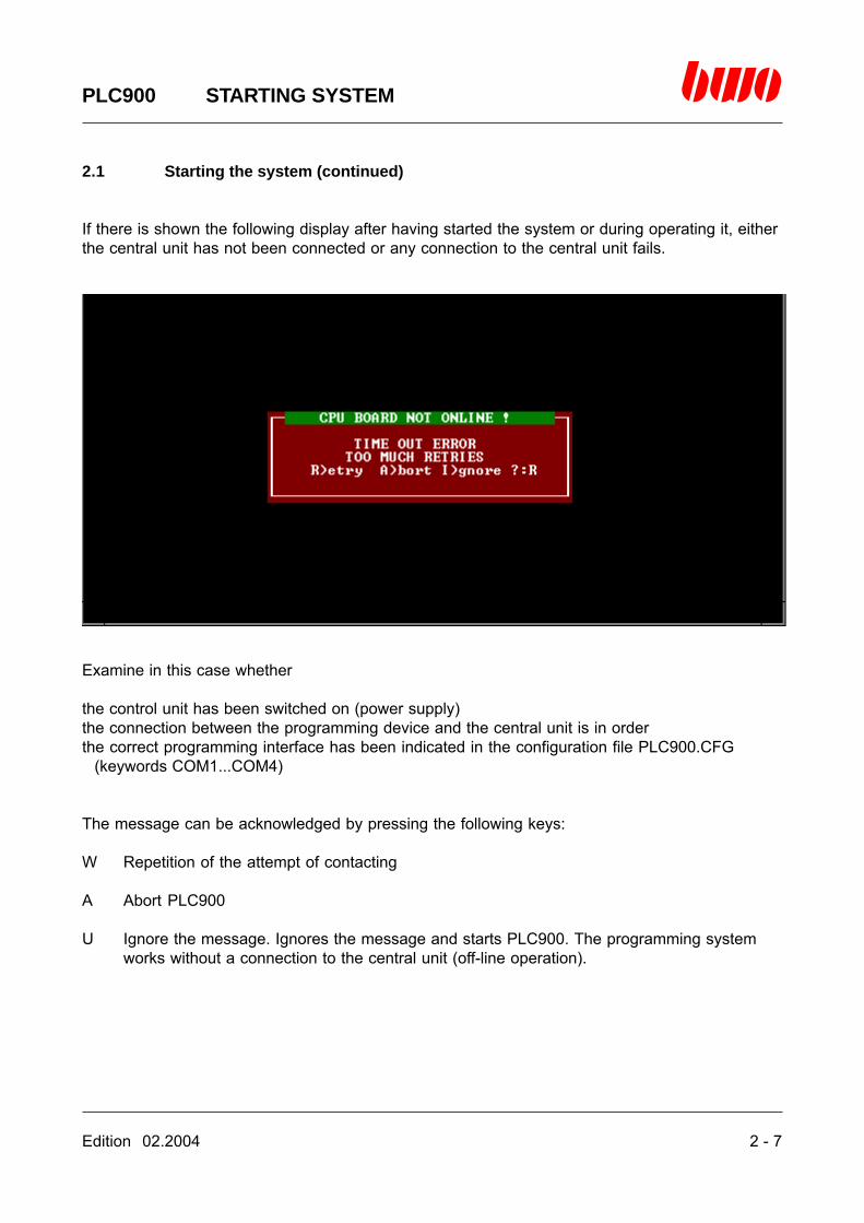
If there is shown the following display after having started the system or during operating it, eitherthe central unit has not been connected or any connection to the central unit fails.
Examine in this case whether
the control unit has been switched on (power supply)the connection between the programming device and the central unit is in orderthe correct programming interface has been indicated in the configuration file PLC900.CFG
(keywords COM1...COM4)
The message can be acknowledged by pressing the following keys:
W Repetition of the attempt of contacting
A Abort PLC900
U Ignore the message. Ignores the message and starts PLC900. The programming systemworks without a connection to the central unit (off-line operation).
2 - 8 Edition 02.2004
PLC900 STARTING SYSTEM
2.1 Starting the system (continued)
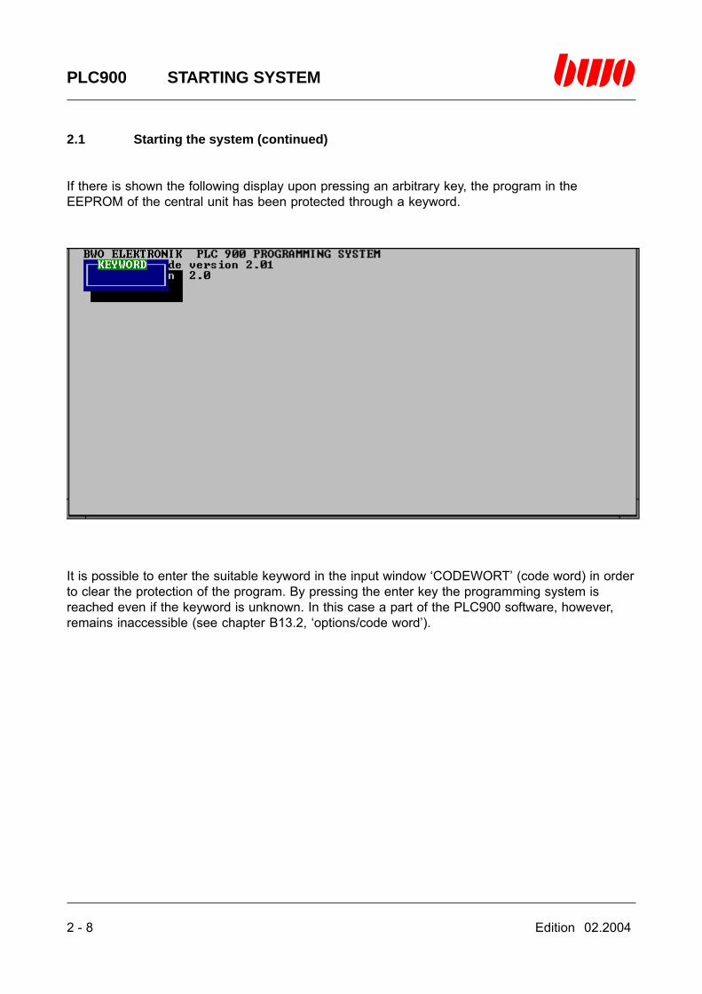
If there is shown the following display upon pressing an arbitrary key, the program in theEEPROM of the central unit has been protected through a keyword.
It is possible to enter the suitable keyword in the input window ‘CODEWORT’ (code word) in orderto clear the protection of the program. By pressing the enter key the programming system isreached even if the keyword is unknown. In this case a part of the PLC900 software, however,remains inaccessible (see chapter B13.2, ‘options/code word’).

Edition 02.2004 2 - 9
PLC900 STARTING SYSTEM
2.1 Starting the system (continued)
If there is shown the following display upon pressing an arbitrary key, the keyword‘QUICK_START’ has been indicated in the configuration file PLC900.CFG. The system comparesthe quick-start program file to the contents of the EEPROM of the central unit.
Upon performing a quick-start, the file [file name].PLC is loaded from the directory that was setduring the last application of the PLC900. [file name] is the name of a PLC900 program file.
If the quick-start has been closed successfully, the PLC900 program is immediately available inthe editor memory and need not be loaded by means of the function ‘File / open’ (chapter B2.3).
Notice: Comparing the quick-start file and the EEPROM contents of the central unit is performedonly by taking samples at random, i.e. if individual instructions should be different, it is not possi-ble to ascertain it.If you want to be sure that the editor contents and the contents of the EEPROM coincide, pleaseload the PLC program via the function ‘File / open’.
2 - 10 Edition 02.2004
PLC900 STARTING SYSTEM
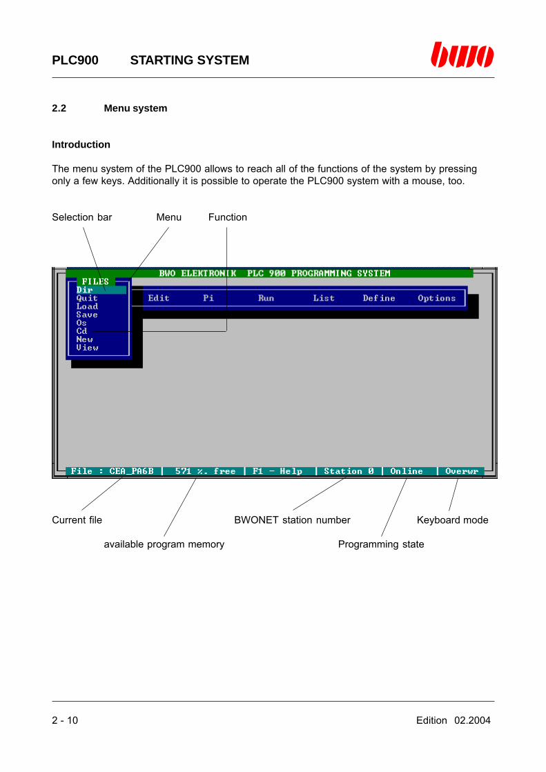
2.2 Menu system
Introduction
The menu system of the PLC900 allows to reach all of the functions of the system by pressingonly a few keys. Additionally it is possible to operate the PLC900 system with a mouse, too.
Selection bar Menu Function
Current file BWONET station number Keyboard mode
available program memory Programming state

Edition 02.2004 2 - 11
PLC900 STARTING SYSTEM
2.2 Menu system (continued)
Selecting a function or a menu:
Move the selection bar to the name of the desired function by means of the cursor control keysand press the enter key
or
press the letter that is marked as a capital letter in the name of the function or of the menu, e.g.‘S’ for the function ‘Save’
or
move the selection bar to the name of the desired function by means of the mouse and press theleft mouse-key.
Escaping from a function or a menu:
Press the <ESC> key
or
press the right mouse-key.
In order to get help, press the keys <F1> or <CTRL J>.

2 - 12 Edition 02.2004
PLC900 STARTING SYSTEM
2.2 Menu system (continued)
Editor control commands in the menu system
Standard Alternatively Function
<ESC> <ALTMODE> Ends menu or function<cursor keys> Move the cursor
<backspace key> <DEL> Blanks the character left of the cursor<DEL> <CTRL G> Blanks the character below the cursor<CTRL Y> Clears the whole line<CTRL QY> Clears the line from the cursor position up
to the line end
<Home> <CTRL QD> Places the cursor on the beginning of theline
<End> <CTRL QS> Places the cursor on the line end
<Insert> <CTRL V> Insertion mode on/off<F1> <CTRL J> Calls on-line help<F2> Starts the symbol editor
Edition 02.2004 2 - 13
PLC900 STARTING SYSTEM
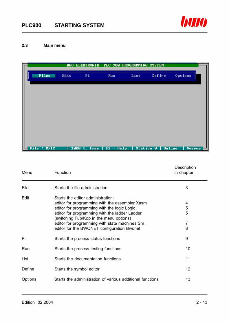
2.3 Main menu
DescriptionMenu Function in chapter
File Starts the file administration 3
Edit Starts the editor administration:editor for programming with the assembler Xasm 4editor for programming with the logic Logic 5editor for programming with the ladder Ladder 5(switching Fup/Kop in the menu options)editor for programming with state machines Sm 7editor for the BWONET configuration Bwonet 8
Pi Starts the process status functions 9
Run Starts the process testing functions 10
List Starts the documentation functions 11
Define Starts the symbol editor 12
Options Starts the administration of various additional functions 13

Edition 02.2004 3 - 1
PLC900 FILES
3. Menu Files
3.1 Directory (Dir) 3 - 3
3.2 Quit 3 - 4
3.3 Load 3 - 5
3.4 Save 3 -13
3.5 DOS shell (Os) 3 -19
3.6 Change directory (Cd) 3 -21
3.7 New 3 -22
3.8 View 3 -23
⌧
3 - 2 Edition 02.2004
PLC900 FILES
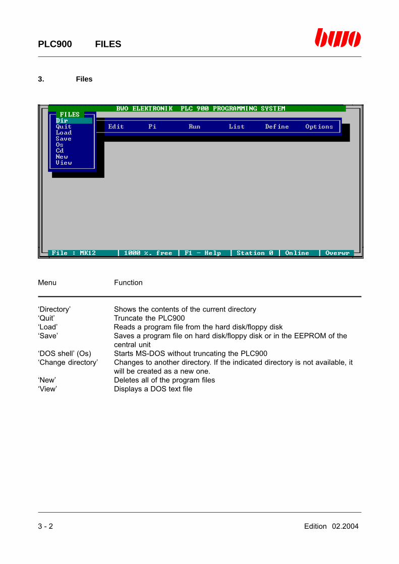
3. Files
Menu Function
‘Directory’ Shows the contents of the current directory‘Quit’ Truncate the PLC900‘Load’ Reads a program file from the hard disk/floppy disk‘Save’ Saves a program file on hard disk/floppy disk or in the EEPROM of the
central unit‘DOS shell’ (Os) Starts MS-DOS without truncating the PLC900‘Change directory’ Changes to another directory. If the indicated directory is not available, it
will be created as a new one.‘New’ Deletes all of the program files‘View’ Displays a DOS text file
Edition 02.2004 3 - 3
PLC900 FILES
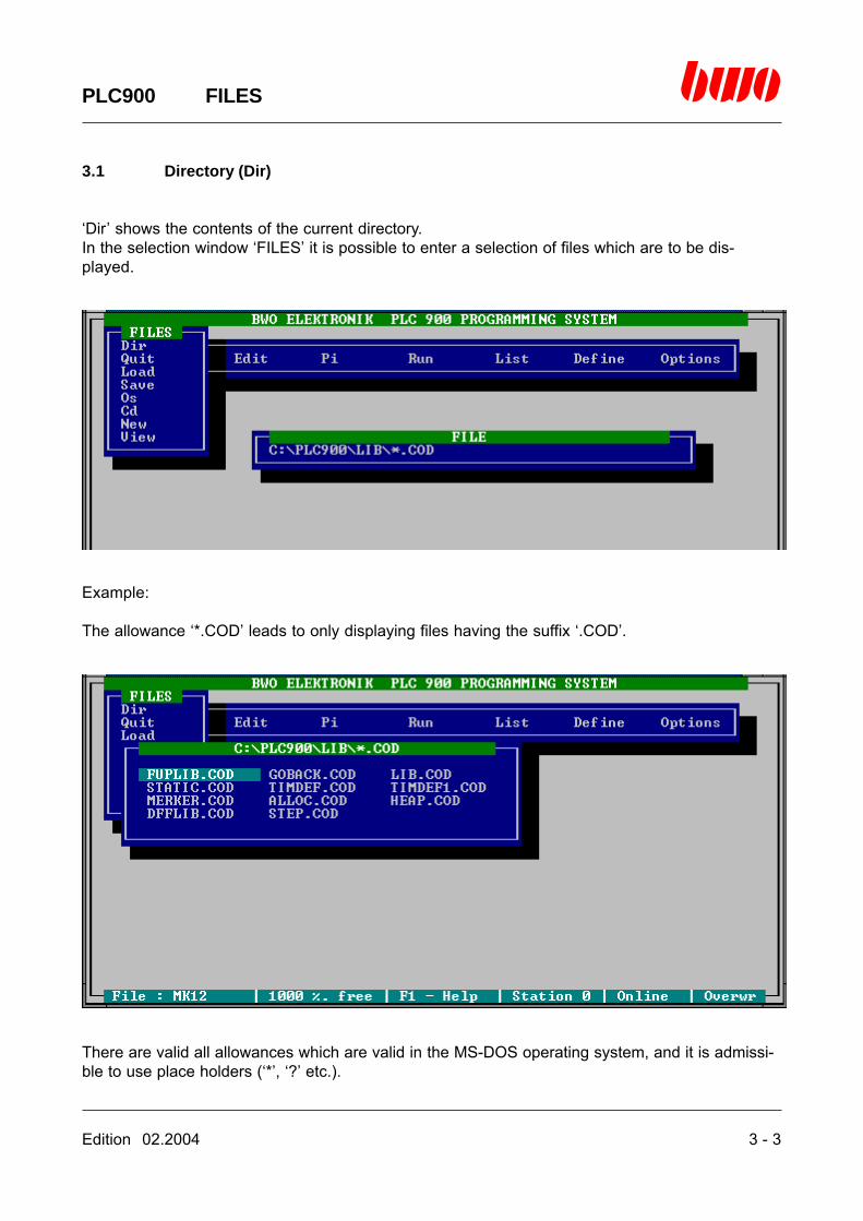
3.1 Directory (Dir)
‘Dir’ shows the contents of the current directory.In the selection window ‘FILES’ it is possible to enter a selection of files which are to be dis-played.
Example:
The allowance ‘*.COD’ leads to only displaying files having the suffix ‘.COD’.
There are valid all allowances which are valid in the MS-DOS operating system, and it is admissi-ble to use place holders (‘*’, ‘?’ etc.).

3 - 4 Edition 02.2004
PLC900 FILES
3.2 Quit
By means of ‘Quit’ the PLC900 programming system is truncated and returning to the DOS leveltakes place.

Edition 02.2004 3 - 5
PLC900 FILES
3.3 Load
‘Load’ reads a program file from the hard disk. In the selection window ‘FILES’ it is possible toenter the name of the files that are to be read.
If there is entered an allowance, e.g. ‘*.COD’ instead of the file name, a digest of all files is dis-played which comply with this allowance. By means of the selection bar the desired file can thenbe selected and loaded by pressing the enter key.
There are the following allowances valid: *.COD *.OBJ *.LNK *.SCR

3 - 6 Edition 02.2004
PLC900 FILES
3.3 Load (continued)
If the file is too large for the editor memory, the following message is shown:
In case of several identical program labels the following message is shown:
In both cases, all of the files have to be deleted by means of the function ‘New’.
Edition 02.2004 3 - 7
PLC900 FILES
3.3 Load (continued)
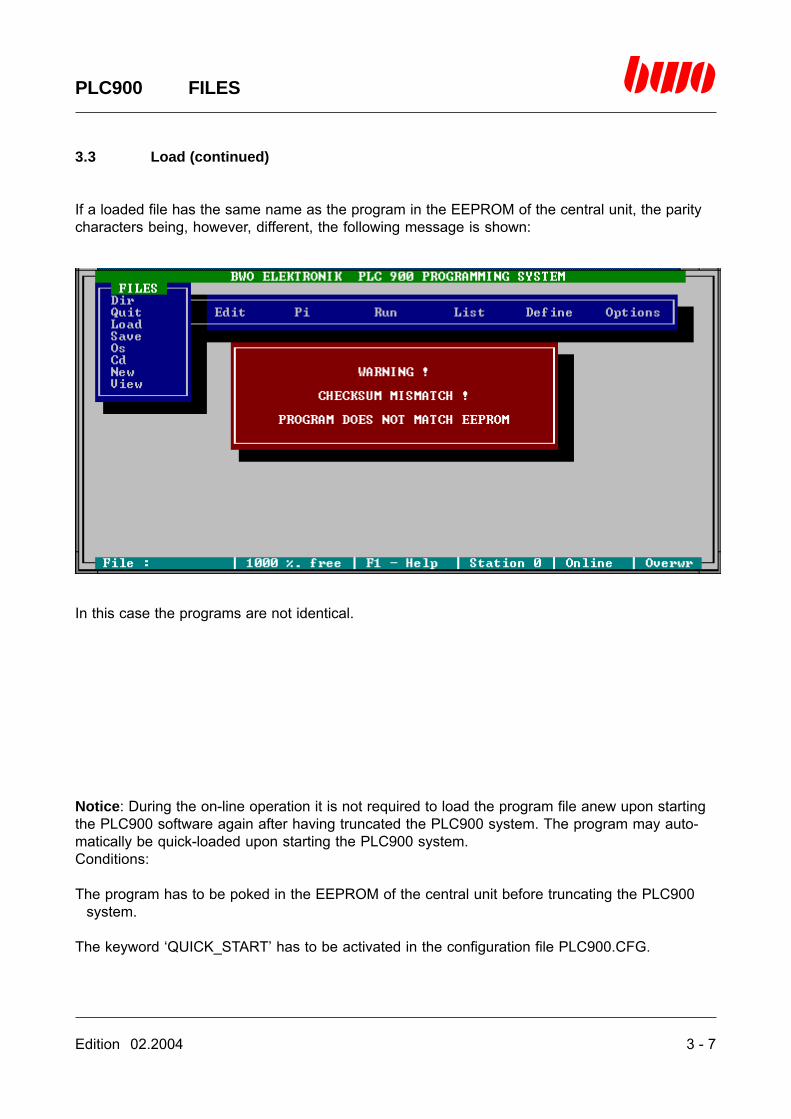
If a loaded file has the same name as the program in the EEPROM of the central unit, the paritycharacters being, however, different, the following message is shown:
In this case the programs are not identical.
Notice: During the on-line operation it is not required to load the program file anew upon startingthe PLC900 software again after having truncated the PLC900 system. The program may auto-matically be quick-loaded upon starting the PLC900 system.Conditions:
The program has to be poked in the EEPROM of the central unit before truncating the PLC900system.
The keyword ‘QUICK_START’ has to be activated in the configuration file PLC900.CFG.

3 - 8 Edition 02.2004
PLC900 FILES
3.3 Load (continued)
Coalescing several programs
In the PLC900 programming system there are two possibilities of coalescing programs:
Simple loading of programs. In this case, the programs are loaded with ‘Save’ and tandem filed inthe editor memory. The flags of the programs are swapped.
Example:
The following instructions (starting from the main menu)
’FILES / Load / [program1].COD’’Load / [program2].COD’’Load / [program3].COD’
attach the programs [program1] [program2] [program3] one after the other.
Loading the programs with the ‘&’ operator. In this case the programs are loaded with ‘Load’ byprefixing the ‘&’ operator in front of each program name.
Here the programs are likewise filed in the editor memory one after the other. The flags of theprograms are, however, tandem loaded, too, as far as they are located in the area betweenM98.1 and M3840.16 and the last used flag has a symbol name.
Example
The following instructions (starting from the main menu)
’FILES / Load / [program1].COD’’Load / [program2].COD’’Load / [program3].COD’
attach the programs [program1] [program2] [program3] as well as their flags one after the other.
Edition 02.2004 3 - 9
PLC900 FILES
3.3 Load (continued)
Link files
A link file is a DOS text file containing the names of files that have been tandem loaded into theeditor of the PLC900 programming system. It is possible to coalesce programs automatically inthis way upon opening them.A link file can be created and processed by means of any DOS editor. The name of the link filemust be
[linkfile].LNK
[linkfile] being the name of the freely selectable link file.By entering the link file name in the selection window ‘FILES’ of the function ‘Load’ the link file isexecuted.
Example:
The following instructions in a link file
[program1].COD&[program2].COD&[program3].COD
attach the programs [program1] [program2] [program3] as well as their flags one after the other.
3 - 10 Edition 02.2004
PLC900 FILES
3.3 Load (continued)
Script files
A script file is a file containing the control commands for the PLC900. The control commands mayconsist of key actions for controlling the menu and of texts for simulating inputs performed bymeans of the keyboard. When a script file is started, the control commands are automaticallyexecuted (automatic system control).A script file can be created and processed by means of any DOS editor. The name of the scriptfile has to be
[scrfile].SCR
[srcfile] being the freely selectable name of the script file.By entering the script file name when starting the PLC900 system, the script file is executed:
Example:
The instruction ‘PLC900 AUTO.SCR’
starts the script file AUTO.SCR
Valid characters in a script file:
Capital letters for controlling the menu systemTexts to be entered in input fields.Control characters.
‘^[‘ = Escape key (‘^’ = ASCII code 95, ‘[‘ = ASCII code 91)‘^M’ = Enter key (‘^’ = ASCII code 95)

Edition 02.2004 3 - 11
PLC900 FILES
3.3 Load (continued)
Example:
A script file having the following contents
^M^MDOTEST.COD^M^[EA
opens the file TEST.COD after having started the PLC900 software and switches to the editorassembler.
In detail there signify
^M^M Ignores the first two messages of the systemD Opens the menu ‘FILES’O Executes the function ‘Load’TEST.COD^M Enters the file name in the input window ‘FILES’ and loads the file^[ Quits the menu ‘FILES’E Opens the menu ‘EDIT’A Executes the function ‘Xasm’
3 - 12 Edition 02.2004
PLC900 FILES
3.3 Load (continued)
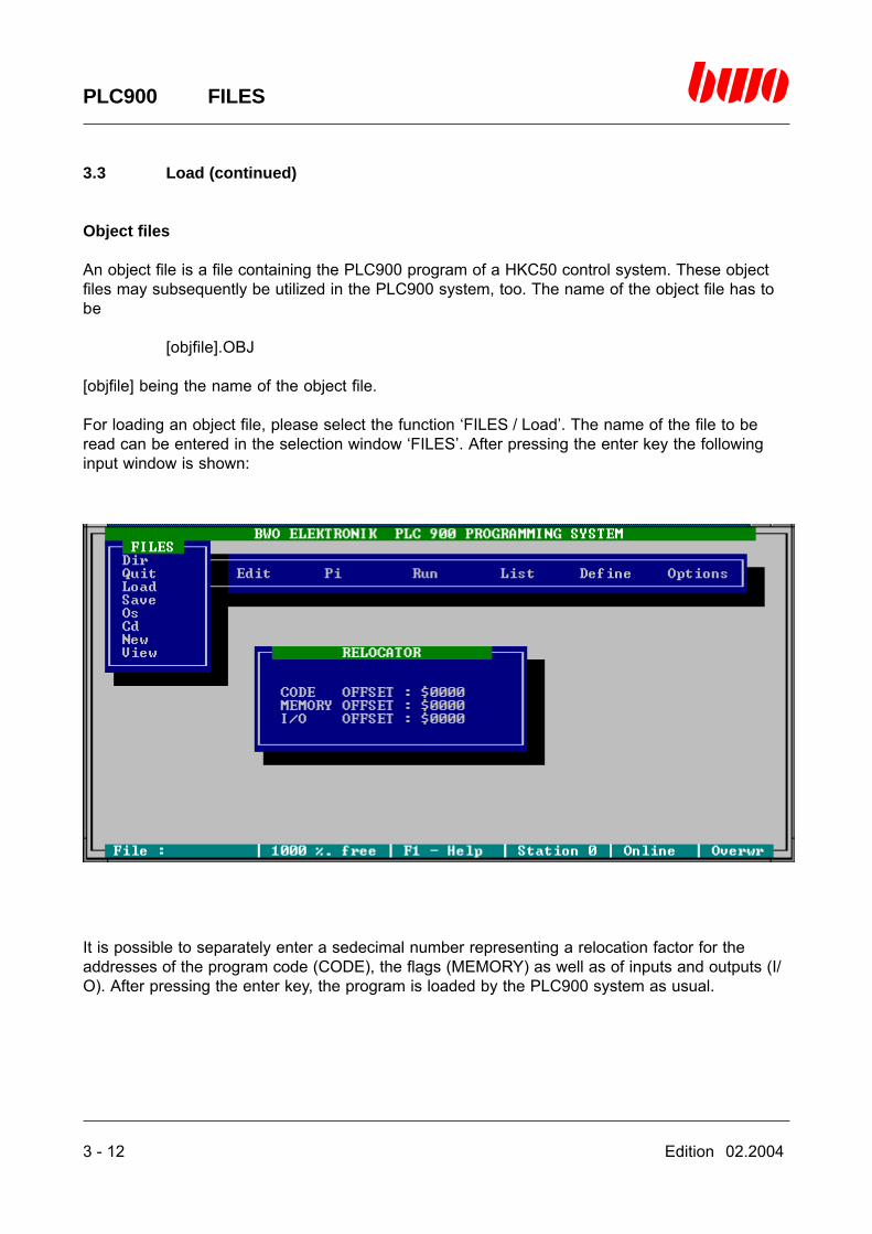
Object files
An object file is a file containing the PLC900 program of a HKC50 control system. These objectfiles may subsequently be utilized in the PLC900 system, too. The name of the object file has tobe
[objfile].OBJ
[objfile] being the name of the object file.
For loading an object file, please select the function ‘FILES / Load’. The name of the file to beread can be entered in the selection window ‘FILES’. After pressing the enter key the followinginput window is shown:
It is possible to separately enter a sedecimal number representing a relocation factor for theaddresses of the program code (CODE), the flags (MEMORY) as well as of inputs and outputs (I/O). After pressing the enter key, the program is loaded by the PLC900 system as usual.
Edition 02.2004 3 - 13
PLC900 FILES
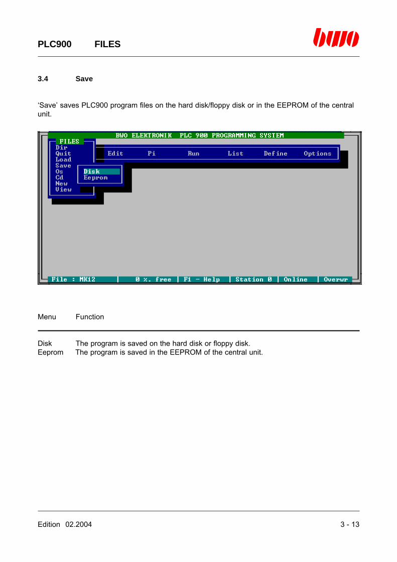
3.4 Save
‘Save’ saves PLC900 program files on the hard disk/floppy disk or in the EEPROM of the centralunit.
Menu Function
Disk The program is saved on the hard disk or floppy disk.Eeprom The program is saved in the EEPROM of the central unit.
3 - 14 Edition 02.2004
PLC900 FILES
3.4 Save (continued)
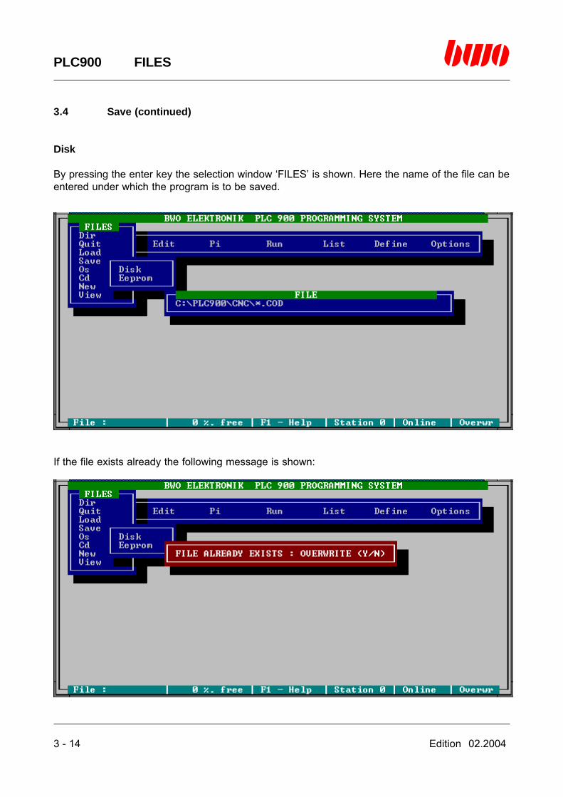
Disk
By pressing the enter key the selection window ‘FILES’ is shown. Here the name of the file can beentered under which the program is to be saved.
If the file exists already the following message is shown:
Edition 02.2004 3 - 15
PLC900 FILES
3.4 Save (continued)
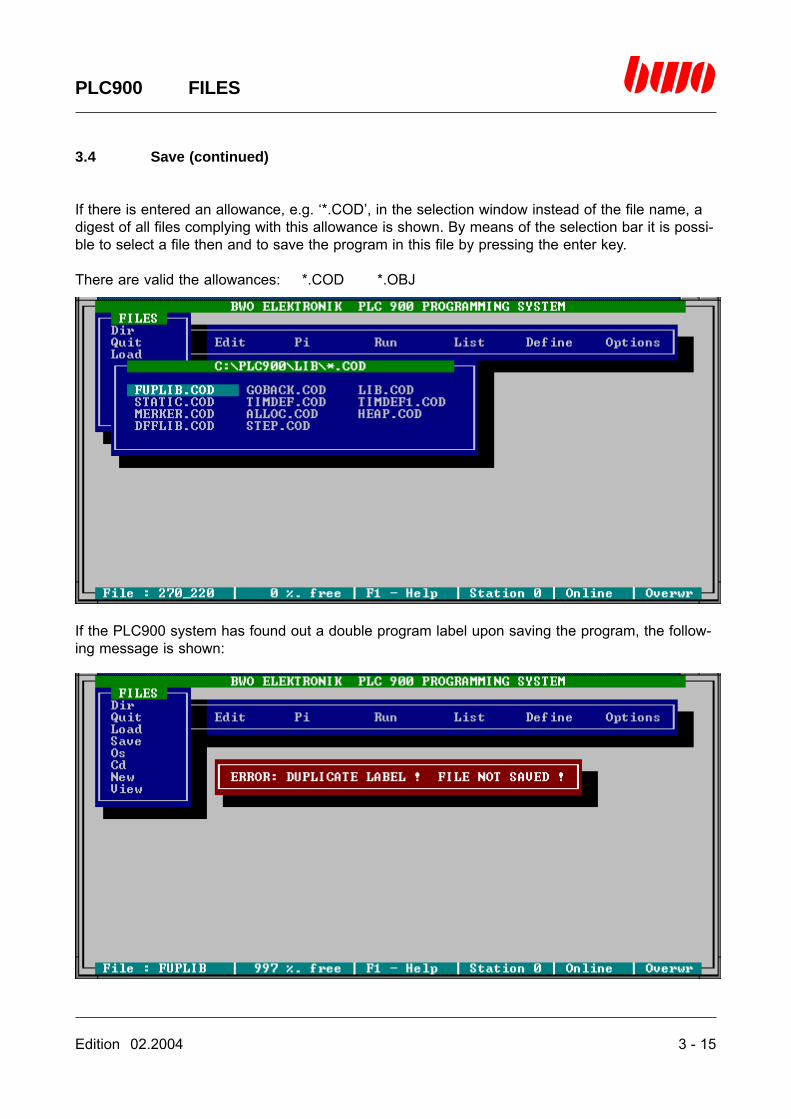
If there is entered an allowance, e.g. ‘*.COD’, in the selection window instead of the file name, adigest of all files complying with this allowance is shown. By means of the selection bar it is possi-ble to select a file then and to save the program in this file by pressing the enter key.
There are valid the allowances: *.COD *.OBJ
If the PLC900 system has found out a double program label upon saving the program, the follow-ing message is shown:
3 - 16 Edition 02.2004
PLC900 FILES
3.4 Save (continued)
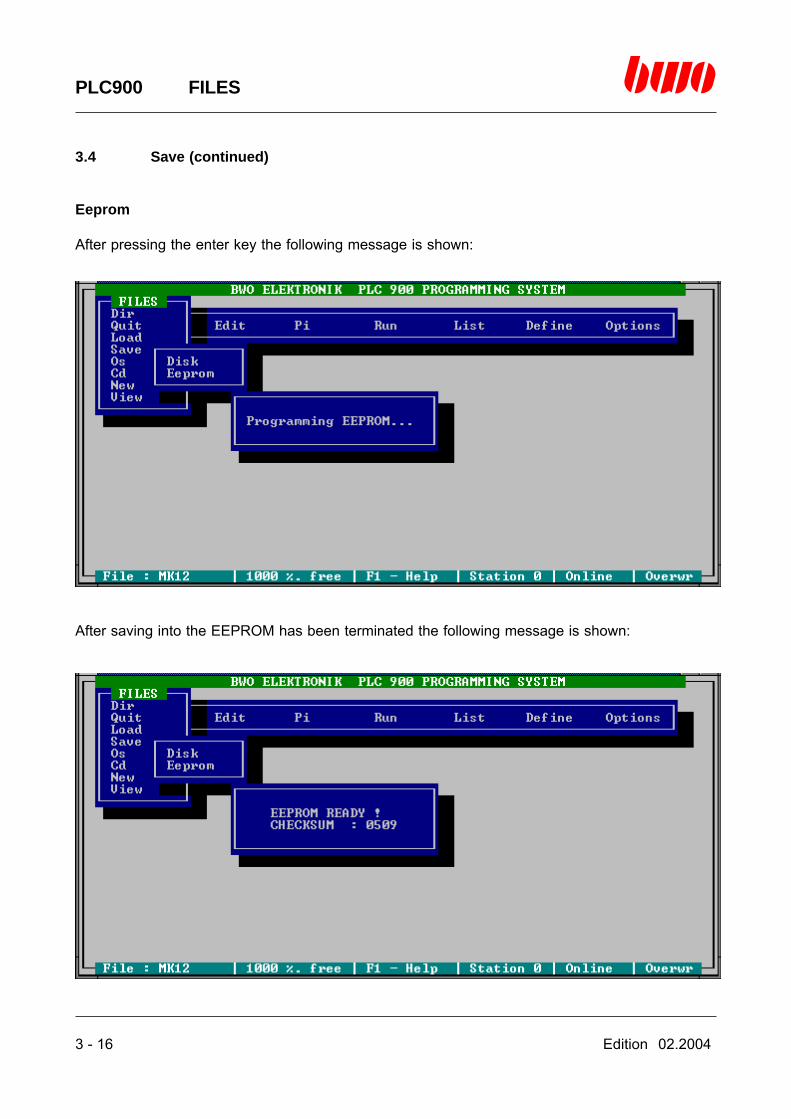
Eeprom
After pressing the enter key the following message is shown:
After saving into the EEPROM has been terminated the following message is shown:

Edition 02.2004 3 - 17
PLC900 FILES
3.4 Save (continued)
In case you have not saved your program on the hard disk or the floppy disk yet, the followingmessage is shown:
The program can only be saved in the EEPROM after you have filed it on the hard disk or floppydisk.
3 - 18 Edition 02.2004
PLC900 FILES
3.4 Save (continued)
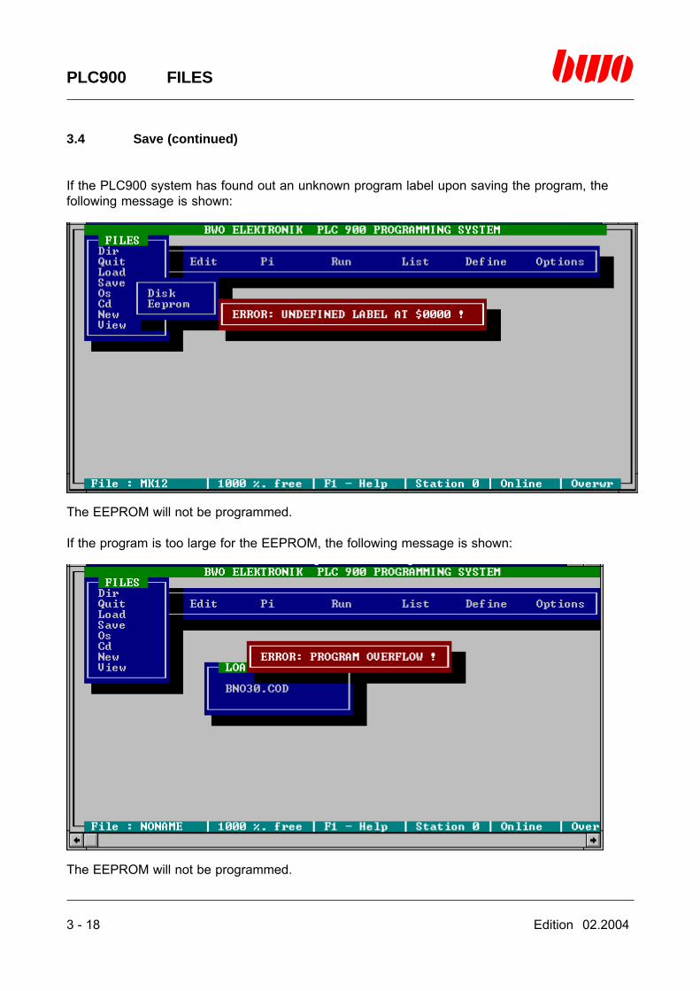
If the PLC900 system has found out an unknown program label upon saving the program, thefollowing message is shown:
The EEPROM will not be programmed.
If the program is too large for the EEPROM, the following message is shown:
The EEPROM will not be programmed.

Edition 02.2004 3 - 19
PLC900 FILES
3.5 DOS shell
By means of ‘Os’ the operating system MS-DOS is started without leaving the PLC900.
In order to get back to the PLC900, please enter the DOS command ‘EXIT’.
3 - 20 Edition 02.2004
PLC900 FILES
3.5 DOS shell (continued)
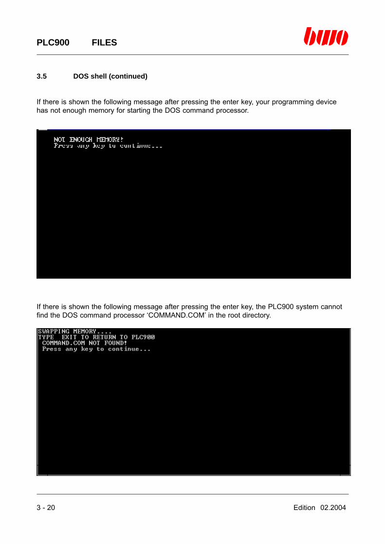
If there is shown the following message after pressing the enter key, your programming devicehas not enough memory for starting the DOS command processor.
If there is shown the following message after pressing the enter key, the PLC900 system cannotfind the DOS command processor ‘COMMAND.COM’ in the root directory.
Edition 02.2004 3 - 21
PLC900 FILES
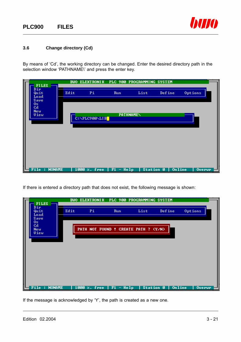
3.6 Change directory (Cd)
By means of ‘Cd’, the working directory can be changed. Enter the desired directory path in theselection window ‘PATHNAME\’ and press the enter key.
If there is entered a directory path that does not exist, the following message is shown:
If the message is acknowledged by ‘Y’, the path is created as a new one.

3 - 22 Edition 02.2004
PLC900 FILES
3.7 New
‘New’ deletes the whole of the program data (!)

Edition 02.2004 3 - 23
PLC900 FILES
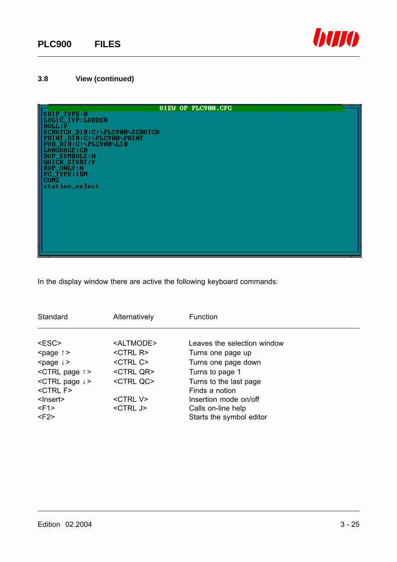
3.8 View
By means of ‘View’, a DOS text file can be displayed. After pressing the enter key, the selectionwindow ‘FILES’ is shown. Here it is possible to enter the name of the file to be displayed.

3 - 24 Edition 02.2004
PLC900 FILES
3.8 View (continued)
If there is entered an allowance, e.g. ‘*.HD’, instead of the file name, a digest of all files complyingwith this allowance is shown.
There are valid all allowances that are valid in the MS-DOS operating system, and it is admissibleto use place holders (‘*’, ‘?’ etc.).
By means of the selection bar, the desired file can then be selected and loaded by pressing theenter key.
Edition 02.2004 3 - 25
PLC900 FILES
3.8 View (continued)
In the display window there are active the following keyboard commands:
Standard Alternatively Function
<ESC> <ALTMODE> Leaves the selection window<page ↑> <CTRL R> Turns one page up<page ↓> <CTRL C> Turns one page down<CTRL page ↑> <CTRL QR> Turns to page 1<CTRL page ↓> <CTRL QC> Turns to the last page<CTRL F> Finds a notion<Insert> <CTRL V> Insertion mode on/off<F1> <CTRL J> Calls on-line help<F2> Starts the symbol editor

Edition 02.2004 4 - 1
PLC900 EDTOR ASSEMBLER (XASM)
4. Editor for programming by means of the assembler (XASM)
4.1 Editor control commands 4 - 2
4.2 Introduction 4 - 3
4.3 Programming 4 - 4
4.4 Range of instructions 4 - 9
⌧

4 - 2 Edition 02.2004
PLC900 EDTOR ASSEMBLER (XASM)
4.1 Editor control commands
Standard Alternatively
<ESC> <ALTMODE> Quits the function<cursor keys> Move the cursor<page ↑> <CTRL R> Turns one page up<page ↓> <CTRL C> Turns one page down<CTRL QR> Puts the cursor on beginning of program<CTRL QC> Puts the cursor on end of program<CTRL QS> Puts the cursor on beginning of line<CTRL QD> Puts the cursor on end of line<TAB> Tabulator
<backspace key> <DEL> Blanks the character left of the curso<DEL> <CTRL G> Blanks the character below the cursor<CTRL Y> Blanks program line<CTRL QY> Blanks the line from the cursor till the end of line<CTRL N> Inserts one program line<CTRL QN> Inserts several program lines
<CTRL F> Searches for an absolute or symbolic address, a symbolname or a label
<CTRL S> Searches for an allocation to an absolute or symbolic address or a symbol name
<CTRL L> Continues searching (search function)
<CTRL KB> Marks the beginning of a block<CTRL KK> Marks the end of a block<CTRL KH> Clears the marking of a block<CTRL KC> Copies a block<CTRL KV> Relocates a block<CTRL KY> Deletes a block<CTRL KR> Reads an ASCII file from the hard disk.
This may only be applied at the end of the program!<CTRL KW> Writes a block as an ASCII file on the hard disk
<CTRL W> Cancels the last alteration(only provided that the cursor has not been moved yet)
<CTRL O> Switches from symbol name to symbolic address andvice versa
<CTRL U> Creates labels on target addresses of branch instructions
<Insert> <CTRL V> Insertion mode on/off<F1> <CTRL J> Calls on-line help<F2> Starts the symbol editor

Edition 02.2004 4 - 3
PLC900 EDTOR ASSEMBLER (XASM)
4.2 Introduction
Programming the system 900 by means of the assembler constitutes the principal item of thePLC900 software. It is possible to control the whole of the functions of the system in the assem-bler (Xasm), e.g. input and output boards, logical operations, arithmetic operations, interfaces forPOS modules or for the CNC900. A program in Xasm consists of a sequence of at most 16368instructions (corresponds to 16K) which are continuously run through anew by means of program-ming a final branch instruction. Upon doing so, a program run is designated as a cycle, and thetime that the PLC requires for processing the instructions is designated as the cycle time. Thecycle time must not be longer than 200ms since otherwise executing the program correctly is nolonger possible. For the purpose of arranging a PLC program, the user disposes of subroutines,modules, logical networks and state machines (see for it the chapters B4 / B5 / B6, too). Moreo-ver, there are offered basic programs with the PLC900 which contain the standard functions suchas POS module drivers as well as state machine and network administration. For further informa-tions please contact BWO-ELEKTRONIK, department Technical Sales.

4 - 4 Edition 02.2004
PLC900 EDTOR ASSEMBLER (XASM)
4.3 Programming
Language elements
Instruction
Syntax:
1st column 2nd column 3rd column 4th column 5th column 6th column
[label] [index] instruction [operand1] [operand2] [*comment]
or *comment
or control signal
The phrases in square brackets are optional. There signify in detail:
Label = symbolic name of program address (program label)Index = instruction index when using the X and Y index registerInstruction = PLC900 instruction
As a matter of principle, it is required to distinguish among instructionswithout operands, with one operand or with two operands
Operand1 = first operand of a PLC900 instruction. Does not exist in case of instructionswith only one operand
Operand2 = second operand of a PLC900 instruction. Does not exist in case of instruc-tions without operands
*comment = line comment only if the operand2 is no memory address having a symbolname
Comment
Syntax:
*comment
Program comment for documenting the PLC900 program. A comment is identified by the leadingstar (‘*’). It is possible to write up to 20 comment lines one after the other which, however, requireonly one program storage location altogether.

Edition 02.2004 4 - 5
PLC900 EDTOR ASSEMBLER (XASM)
4.3 Programming (continued)
Control signal
Syntax:
*EJE
Control signal for making up a page upon outputting a PLC900 program to a printer.
LabelA program label identifies a program line with a symbolic name. The symbolic name consists ofseven characters in arbitrary order and may be used in the program only once.
Example: Using a program label ‘START’
0000 NOP0001 START L M1.10002 U M1.20003 = A1.1.10004 NOP0005 JMP START *jump to the program address 00010006 NOP0007 END
Index
Index registers X and Y. The two index registers X and Y allow to address indirectly in the PLC900system.

4 - 6 Edition 02.2004
PLC900 EDTOR ASSEMBLER (XASM)
4.3 Programming (continued)
Operands
The two operands of the PLC900 instructions can constitute a constant or an address dependingon the instruction.
Numeric constants
110 decimal number$64 sedecimal number’73 octal number
Symbol constants
1.20 time (here: 1.2 seconds)START program label
Symbolic address
M1.5 flagO1.4.2 outputI1.7.1 input
Symbol name
SNOT, BSTEIN, coolanE, axis1, etc.
Please find further details for representing operands in chapter 12.
Edition 02.2004 4 - 7
PLC900 EDTOR ASSEMBLER (XASM)
4.3 Programming (continued)
Register
IS register
The internal status register IS serves for storing the result of logical operation with Booleaninstructions intermediately. It is written resp. Read exclusively by the PLC900 system.
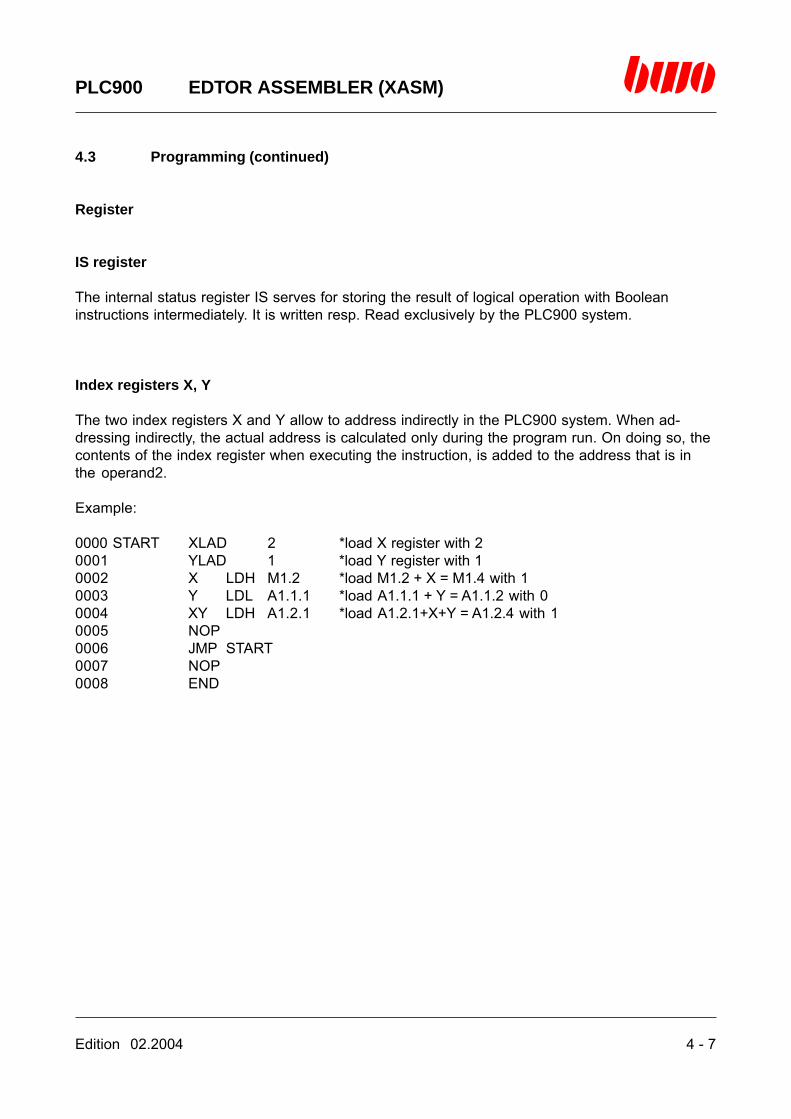
Index registers X, Y
The two index registers X and Y allow to address indirectly in the PLC900 system. When ad-dressing indirectly, the actual address is calculated only during the program run. On doing so, thecontents of the index register when executing the instruction, is added to the address that is inthe operand2.
Example:
0000 START XLAD 2 *load X register with 20001 YLAD 1 *load Y register with 10002 X LDH M1.2 *load M1.2 + X = M1.4 with 10003 Y LDL A1.1.1 *load A1.1.1 + Y = A1.1.2 with 00004 XY LDH A1.2.1 *load A1.2.1+X+Y = A1.2.4 with 10005 NOP0006 JMP START0007 NOP0008 END

4 - 8 Edition 02.2004
PLC900 EDTOR ASSEMBLER (XASM)
4.3 Programming (continued)
TOS register
In order to be able to execute arithmetic operations and memory manipulations quickly and effec-tively, the TOS register is at disposal. TOS thereby stands for ‘Top of stack’. The TOS register inwhich the memory contents can be taken and written only at the location the so-called stack-pointer SP points at, consists of 32 registers having a width of 4 bytes. When storing a value inthe TOS, the SP is increased by on register, when reading a value from the TOS, the SP is de-creased by one register. Administrating the SP is solely taken over by the PLC900 system.
TOS - 31
TOS - 2
TOS - 1
SP -> TOS

Edition 02.2004 4 - 9
PLC900 EDTOR ASSEMBLER (XASM)
4.4 Range of instructions
In the description of the range of instructions there is applied the following notation:
madress Memory address (flag, input, output) + contents of the X and Y registers
iadress Absolute address, relative address, label or program address

4 - 10 Edition 02.2004
PLC900 EDTOR ASSEMBLER (XASM)
4.4 Range of instructions (continued)
Loading from the TOS register
LCS (constant) Loads the lower 16 bits of the TOS register. Through an algebraic sign thenumber is extended to 32 bits. The stackpointer is automatically increased.
LCHS (constant) Loads the upper 16 bits of the TOS register.The stackpointer remains unaltered !
LXS Loads the X register into the TOS register.The stackpointer is increased automatically.
LYS Loads the Y register into the TOS register.The stackpointer is automatically increased.
LRS madress Loads 4 resp. 2 bytes of the memory from an arbitrary memory addressinto the TOS register (32bit resp. 16bit, see SIZE).The stackpointer is automatically increased.
BLRS madress Loads 1 byte of the memory from an arbitrary memory address into theTOS register (8bit). The stackpointer is automatically increased.
LSR madress Loads the TOS register starting at an arbitrary memory address into thememory (4 resp. 2 bytes, see SIZE).The stackpointer is automatically increased.
BLRS madress Loads the TOS register starting at an arbitrary memory address into thememory (1 byte). The stackpointer is automatically increased.
LEAS Reading E / A / M onto the stack (TOS).Conditions: TOS (number of flags <= 32)
TOS-1 (starting address)The data are slid into the TOS from right to left (LSB).After reading them, the stackpointer is corrected. See FWD / BWD.
LSEA Writing A / M out of the stack (TOS).Conditions: TOS (number of flags <= 32)
TOS-1 (target address)TOS-2 (data contents)
The data are slid from the TOS from left to right into the memory (LSB).After reading them, the stackpointer is corrected. See FWD / BWD.

Edition 02.2004 4 - 11
PLC900 EDTOR ASSEMBLER (XASM)
4.4 Range of instructions (continued)
Loading from the registers X and Y
X LAD (constant) Loads the X register.
Y LAD (constant) Loads the Y register.
LSX Load the TOS register into the X register.The stackpointer is automatically decreased.
LSY Loads the TOS register into the Y register.The stackpointer is automatically decreased.
EXY The contents of the X and the Y register are interchanged.
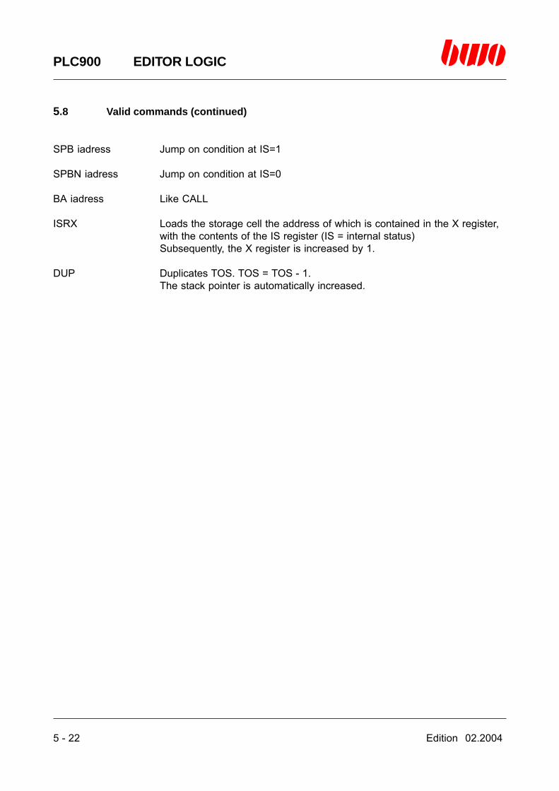
ISRX Loads the storage cell the address of which is contained in the X register,with the contents of the IS register (IS = internal status).Subsequently, the X register is increased by 1.
XISR Loads the IS register with the contents of the storage cell the address ofwhich is contained in the X register.Subsequently, the X register is increased by 1.

4 - 12 Edition 02.2004
PLC900 EDTOR ASSEMBLER (XASM)
4.4 Range of instructions (continued)
Loading the memory
LDL madress Loads an arbitrary memory address with 0 (L)
LDH madress Loads an arbitrary memory address with 1 (H)
FILL b n Fills n memory cells with a value (b) starting at the starting address that iscontained in the X register. See FWD/BWD.
EFILL Like FILL; but the parameters are located inTOS = numberTOS-1 = addressTOS-2 = sample
MOVE n Transfers n memory cells.The source address is in the Y register.The target address is in the X register.See FWD/BWD.
EMOVE Like MOVE, but the parameters are located inTOS = numberTOS-1 = target addressTOS-2 = source address

Edition 02.2004 4 - 13
PLC900 EDTOR ASSEMBLER (XASM)
4.4 Range of instructions (continued)
Controlling the program
NOP No operation.
JMP iadress Jump to an absolute address.
SP iadress Jump to an absolute address.
JMPT iadress Jump on condition to an absolute address if TOS = 1.The stackpointer is automatically decreased.
JMPF iadress Jump on condition to an absolute address if TOS = 0.The stackpointer is automatically decreased.
SPB iadress Jump on condition at IS=1.
SPBN iadress Jump on condition at IS=0.
CALL iadress Calling a subroutine.
BA iadress Like CALL.
SBT iadress Starts background-TASK.
RET End of subroutine or end of the background-TASK.
BE Like RET.
DCD iadress Calculated jump. The program jumps to the address = TOS + iadress.The stackpointer is automatically decreased.
SIZE n n=4 : 32bit processingn=2 : 16bit processing.Switches the word instructions from 32bit (4bytes) to 16bit (2bytes).
END End of program.This has to be the last instruction in the program !

4 - 14 Edition 02.2004
PLC900 EDTOR ASSEMBLER (XASM)
4.4 Range of instructions (continued)
Test statements
X DCR n (X register) - 1; if X = 0 , skipping over n instructions is executed.(n <= 10)
Y DCR n (Y register) - 1; if Y = 0 , skipping over n instructions is executed.(n <= 10)
TEQ Requesting whether TOS-1 = TOS. The stackpointer is automaticallydecreased.TOS = 1 if the request is true.TOS = 0 if the request is false.
TGT Requesting whether TOS-1 > TOS. The stackpointer is automaticallydecreased.TOS = 1 if the request is true.TOS = 0 if the request is false.
TLT Request whether TOS-1 < TOS. The stackpointer is automaticallydecreased.TOS = 1 if the request is true.TOS = 0 if the request is false.
SL n madress Skip over n instructions if the LSB bit of the byte of the target address(madress) is 0. (n <= 10)
SH n madress Skip over n instructions if the LSB bit of the byte of the target address(madress) is 1. (n <= 10)
ST n adress Start the “Timer” an skip over n instructions as long as the timer is running.(n <= 10)
SNT n adress Start the “Timer” an skip over n instructions as soon as the timer haselapsed. (n <= 10)
ET adress Reset the timer.IST n adress Start the “Timer” and skip over n instructions
as long as the timer is running. (n <= 10)Additionally, the X register is added to the address.
ISNT n adress Start the “Timer” and skip over n instructionsas soon as the timer has elapsed. (n <= 10)Additionally, the X register is added to the address.
IET adress Reset the timer.Additionally, the X register is added to the address.

Edition 02.2004 4 - 15
PLC900 EDTOR ASSEMBLER (XASM)
4.4 Range of instructions (continued)
Arithmetic instructions
Upon entering the following 5 instructions the stackpointer is automatically decreased.
ADD TOS = TOS-1 + TOS
UB TOS = TOS-1 - TOS
MUL TOS = TOS-1 * TOS
DIV TOS = TOS-1 / TOS
REM TOS = TOS-1 mod TOS
NEG TOS = - TOSThe stackpointer remains unaltered.
INC madress Increase by 1the storage cell on address (madress)(4byte register).
DEC madress Decrease by 1the storage cell on address (madress)(4byte register).
X IADD constant Add a constant on the X register.
Y IADD constant Add a constant on the Y register.
4 - 16 Edition 02.2004
PLC900 EDTOR ASSEMBLER (XASM)
4.4 Range of instructions (continued)
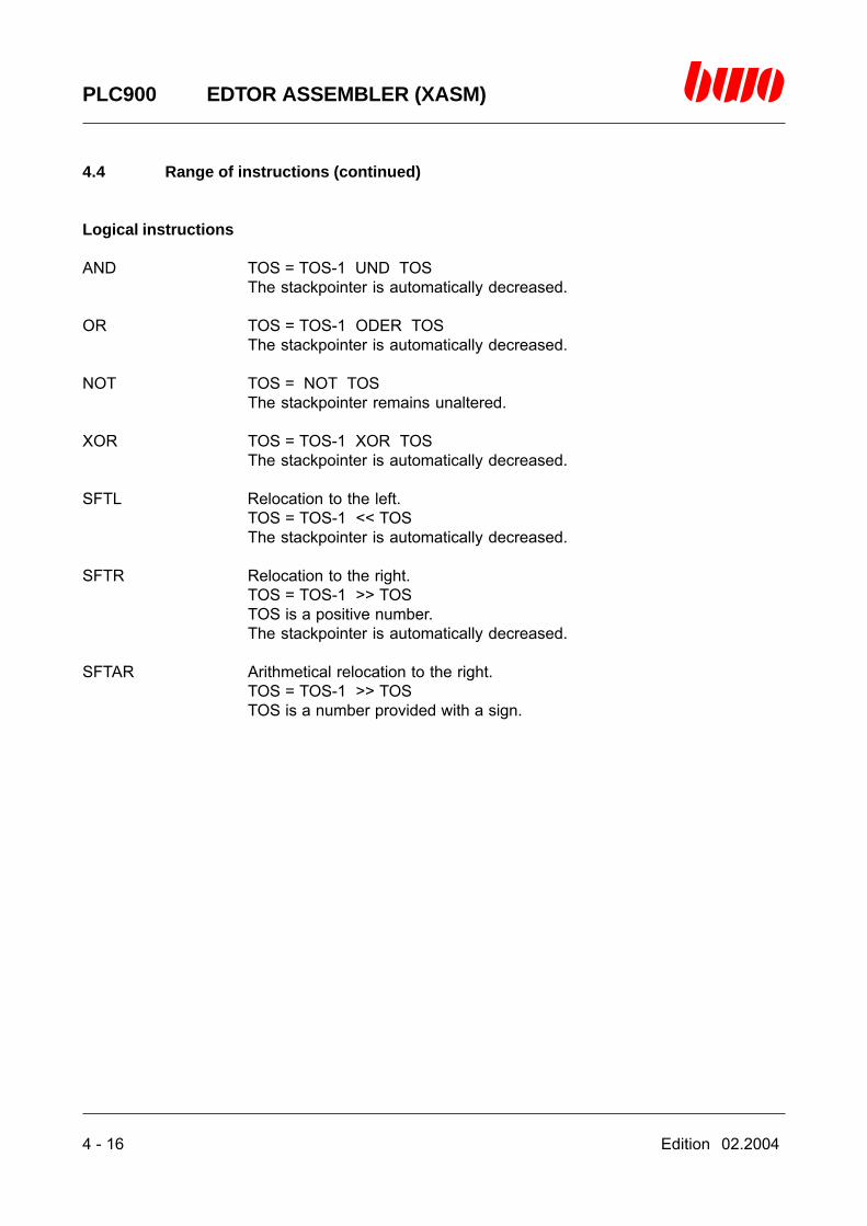
Logical instructions
AND TOS = TOS-1 UND TOSThe stackpointer is automatically decreased.
OR TOS = TOS-1 ODER TOSThe stackpointer is automatically decreased.
NOT TOS = NOT TOSThe stackpointer remains unaltered.
XOR TOS = TOS-1 XOR TOSThe stackpointer is automatically decreased.
SFTL Relocation to the left.TOS = TOS-1 << TOSThe stackpointer is automatically decreased.
SFTR Relocation to the right.TOS = TOS-1 >> TOSTOS is a positive number.The stackpointer is automatically decreased.
SFTAR Arithmetical relocation to the right.TOS = TOS-1 >> TOSTOS is a number provided with a sign.

Edition 02.2004 4 - 17
PLC900 EDTOR ASSEMBLER (XASM)
4.4 Range of instructions (continued)
Conversion instructions
IBCD Converts TOS from Integer into BCD.The stackpointer remains unaltered.
BCDI Converts TOS from BCD into Integer.The stackpointer remains unaltered.
4 - 18 Edition 02.2004
PLC900 EDTOR ASSEMBLER (XASM)
4.4 Range of instructions (continued)
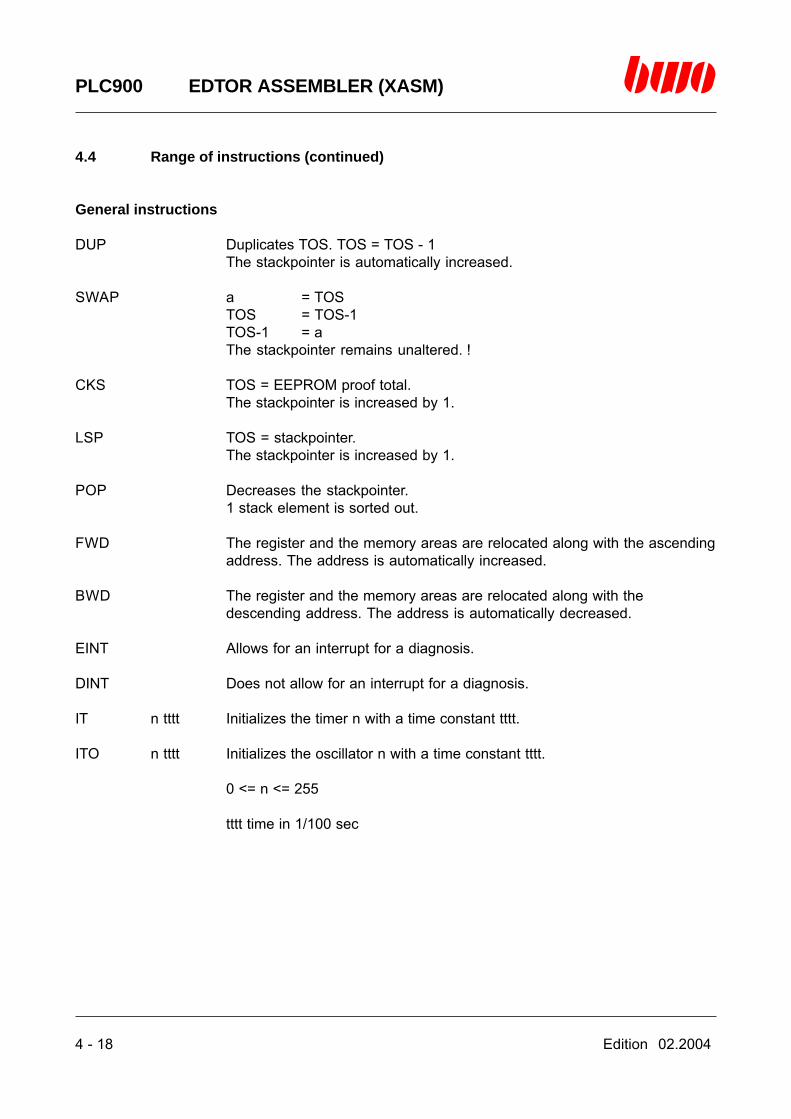
General instructions
DUP Duplicates TOS. TOS = TOS - 1The stackpointer is automatically increased.
SWAP a = TOSTOS = TOS-1TOS-1 = aThe stackpointer remains unaltered. !
CKS TOS = EEPROM proof total.The stackpointer is increased by 1.
LSP TOS = stackpointer.The stackpointer is increased by 1.
POP Decreases the stackpointer.1 stack element is sorted out.
FWD The register and the memory areas are relocated along with the ascendingaddress. The address is automatically increased.
BWD The register and the memory areas are relocated along with thedescending address. The address is automatically decreased.
EINT Allows for an interrupt for a diagnosis.
DINT Does not allow for an interrupt for a diagnosis.
IT n tttt Initializes the timer n with a time constant tttt.
ITO n tttt Initializes the oscillator n with a time constant tttt.
0 <= n <= 255
tttt time in 1/100 sec

Edition 02.2004 4 - 19
PLC900 EDTOR ASSEMBLER (XASM)
4.4 Range of instructions (continued)
Boolean instructions
L adress Loads the first operand.
LX adress Loads the first operand with register X.
LY adress Loads the first operand with register Y.
LXY adress Loads the first operand with register XY.
U adress AND-operator
O adress OR-operator
= adress Stores the result.
S adress Sets flag / output.
R adress Resets flag / output.
LN adress Negation of L.
UN adress Negation of U
ON adress Negation of O.
=N adress Negation of =.
SN adress Sets flag / output if IS = 0
RN adress Resets flag / output if IS = 0
Application of bracket terms:
( , U( , UN( , O( , ON( , N( , )

4 - 20 Edition 02.2004
PLC900 EDTOR ASSEMBLER (XASM)
4.4 Range of instructions (continued)
Timer
It is possible to define up to 255 timers Starting address may be every valid flag address.
Timers have the following structure :
First counter: 0 Check word1 Status word2 Max. counter value3 Max. counter value4 Counter5 Counter
Next counter: 6 Check word...
Management of the timer
See IT, ITO, ST, SNT, ET, IST, ISNT, IET
Notice: The time base of a timer is 10ms.

Edition 02.2004 5 - 1
PLC900 EDITOR LOGIC
5. Editor for programming by means of the logic
5.1 Editor control commands 5 - 2
5.2 Introduction 5 - 3
5.3 Programming networks 5 - 4
5.4 Starting the editor 5 - 7
5.5 Editor functions 5 -13
5.6. Compatibility of the ladder and the logic 5 -18
5.7 The menu tree of the logic editor 5 -20
5.8 Valid commands 5 -21
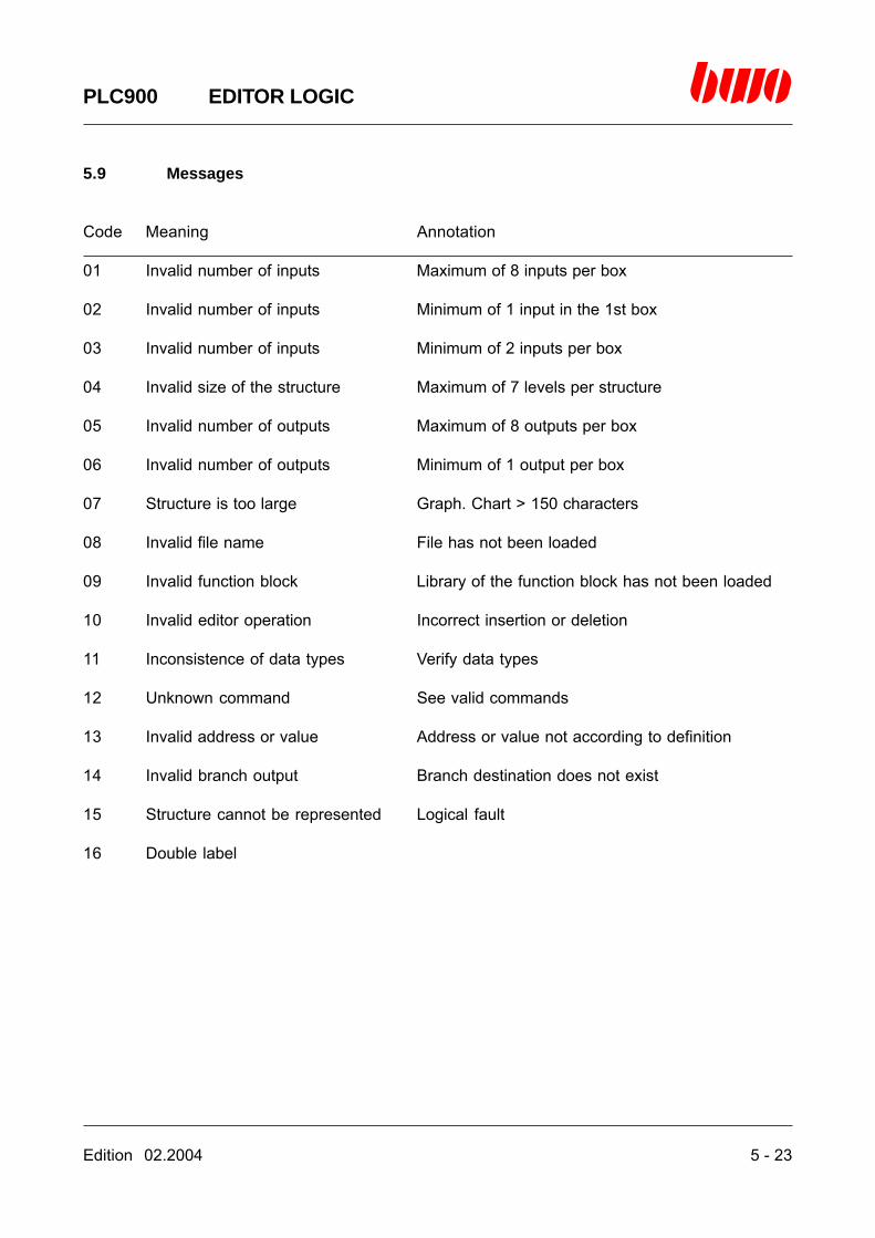
5.9 Messages 5 -23
⌧

5 - 2 Edition 02.2004
PLC900 EDITOR LOGIC
5.1 Editor control commands
Standard Alternatively Function
<ESC> <ALTMODE> Quits the menu or the function
<cursor keys> Move the cursor
<space bar> Selects the menu
<enter key> Selects the menu or the function
<page ↑> <CTRL R> Turns one page up<page ↓> <CTRL C> Turns one page down
<CTRL QS> Turns one page left<CTRL QD> Turns one page right
<CTRL X> Switches between symbolic address and symbolname
<CTRL L> Searches for next address (see searchingfunctions)
<CTRL KB> Marks a block<CTRL KH> Clears the marking<CTRL KC> Copies a block<CTRL KV> Relocates a block
<Insert> <CTRL V> Insertion mode on/off
<F1> <CTRL J> Calls on-line help
<F2> Starts the symbol editor
Edition 02.2004 5 - 3
PLC900 EDITOR LOGIC
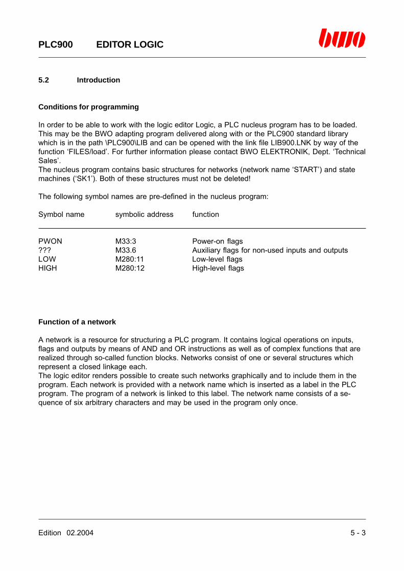
5.2 Introduction
Conditions for programming
In order to be able to work with the logic editor Logic, a PLC nucleus program has to be loaded.This may be the BWO adapting program delivered along with or the PLC900 standard librarywhich is in the path \PLC900\LIB and can be opened with the link file LIB900.LNK by way of thefunction ‘FILES/load’. For further information please contact BWO ELEKTRONIK, Dept. ‘TechnicalSales’.The nucleus program contains basic structures for networks (network name ‘START’) and statemachines (‘SK1’). Both of these structures must not be deleted!
The following symbol names are pre-defined in the nucleus program:
Symbol name symbolic address function
PWON M33:3 Power-on flags??? M33.6 Auxiliary flags for non-used inputs and outputsLOW M280:11 Low-level flagsHIGH M280:12 High-level flags
Function of a network
A network is a resource for structuring a PLC program. It contains logical operations on inputs,flags and outputs by means of AND and OR instructions as well as of complex functions that arerealized through so-called function blocks. Networks consist of one or several structures whichrepresent a closed linkage each.The logic editor renders possible to create such networks graphically and to include them in theprogram. Each network is provided with a network name which is inserted as a label in the PLCprogram. The program of a network is linked to this label. The network name consists of a se-quence of six arbitrary characters and may be used in the program only once.

5 - 4 Edition 02.2004
PLC900 EDITOR LOGIC
5.3 Programming networks
Format of the symbols
Allocation
Address = symbolic address or symbol nameInputs maximum of 1Outputs maximum of 8 parallel steps
AND box
Address = symbolic address or symbol nameInputs maximum of 8Outputs maximum of 8 parallel steps
OR box
Address = symbolic address or symbol nameInputs maximum of 1Outputs maximum of 8 parallel steps
Address Address
AddressAddress Address
&
AddressAddress Address
>=1

Edition 02.2004 5 - 5
PLC900 EDITOR LOGIC
5.3 Programming networks
Function block
Addr/value = symbolic address, symbol name or constantAddress = symbolic address or symbol nameInputs maximum of 8Outlets maximally 8 parallel steps
You will find further information about function blocks in the chapters C1 and C2.
Symbolic address
Station, local BWONET Example
Flag M[g].[n] M[st].[g].[n] M1.2, M2.4.1
Input I[st].[sl].[e] I[st].[sl].[e] I1.3.17, I2.6.22
Output O[st].[sl].[a] O[st].[sl].[a] O1.1.9, O3.4.11
[g] = Group number (1..3840)[n] = Bit or register number (1..16)[st] = Station number (1..255)[sl] = Slot number (1..32)[e] = Input number (1..32)[a] = Output number (1..32)
Address
Address
(00000)
Addr/valueAddr/valueAddr/valueAddr/value A
FUBE1E2E3E4

5 - 6 Edition 02.2004
PLC900 EDITOR LOGIC
5.3 Programming networks
Symbol name
A symbol name is a sequence of 7 characters which represents a designation for the utilization ofan input, output or flag.
Examples:
SNOT, BSTEIN, coolanE, axis1
You will find more details in chapter 12.1.
Constant
Numerical constants
110 decimal number$64 hexadecimal number‘73 octal number
Symbol constants
%M2.4 address of a flag or register%I1.4.5 address of an input%O1.12.16 address of an outputT1.20 time (here: 1.2 seconds)
Jump constants
>>END jump to network label ‘END’
Network size
Limitations of the size of networks only result from the size of the editor screen and from thememory of the programming device.
Screen format 125 × 150 characters

Edition 02.2004 5 - 7
PLC900 EDITOR LOGIC
5.4 Starting the editor
Select the function ‘Logic’ in the menu ‘EDITOR’ and press the enter key.The selection window ‘NETWORK’ is shown. Here, the name of the network that is to be editedcan be entered.
If no network name is entered, a digest of all networks is shown.
5 - 8 Edition 02.2004
PLC900 EDITOR LOGIC
5.4 Starting the editor (continued)
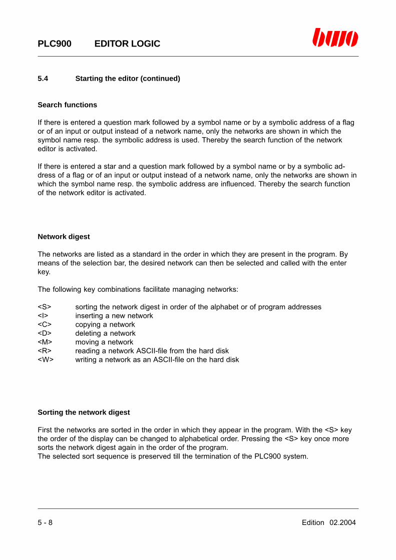
Search functions
If there is entered a question mark followed by a symbol name or by a symbolic address of a flagor of an input or output instead of a network name, only the networks are shown in which thesymbol name resp. the symbolic address is used. Thereby the search function of the networkeditor is activated.
If there is entered a star and a question mark followed by a symbol name or by a symbolic ad-dress of a flag or of an input or output instead of a network name, only the networks are shown inwhich the symbol name resp. the symbolic address are influenced. Thereby the search functionof the network editor is activated.
Network digest
The networks are listed as a standard in the order in which they are present in the program. Bymeans of the selection bar, the desired network can then be selected and called with the enterkey.
The following key combinations facilitate managing networks:
<S> sorting the network digest in order of the alphabet or of program addresses<I> inserting a new network<C> copying a network<D> deleting a network<M> moving a network<R> reading a network ASCII-file from the hard disk<W> writing a network as an ASCII-file on the hard disk
Sorting the network digest
First the networks are sorted in the order in which they appear in the program. With the <S> keythe order of the display can be changed to alphabetical order. Pressing the <S> key once moresorts the network digest again in the order of the program.The selected sort sequence is preserved till the termination of the PLC900 system.

Edition 02.2004 5 - 9
PLC900 EDITOR LOGIC
5.4 Starting the editor (continued)
Inserting a network
First the selection bar has to be moved to the position by means of the cursor control keys wherethe network is to be inserted. After pressing the <I> key the input window ‘NETWORK NAME’ isshown. Here the name of the new network is entered.
After pressing the enter key the network is inserted ahead of the network in the program that wasselected with the selection bar and is then displayed immediately.
Deleting a network
By means of the selection bar the desired file can be selected. After pressing the <D> key thenetwork is deleted.
5 - 10 Edition 02.2004
PLC900 EDITOR LOGIC
5.4 Starting the editor (continued)
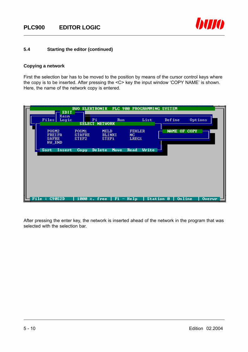
Copying a network
First the selection bar has to be moved to the position by means of the cursor control keys wherethe copy is to be inserted. After pressing the <C> key the input window ‘COPY NAME’ is shown.Here, the name of the network copy is entered.
After pressing the enter key, the network is inserted ahead of the network in the program that wasselected with the selection bar.
Edition 02.2004 5 - 11
PLC900 EDITOR LOGIC
5.4 Starting the editor (continued)
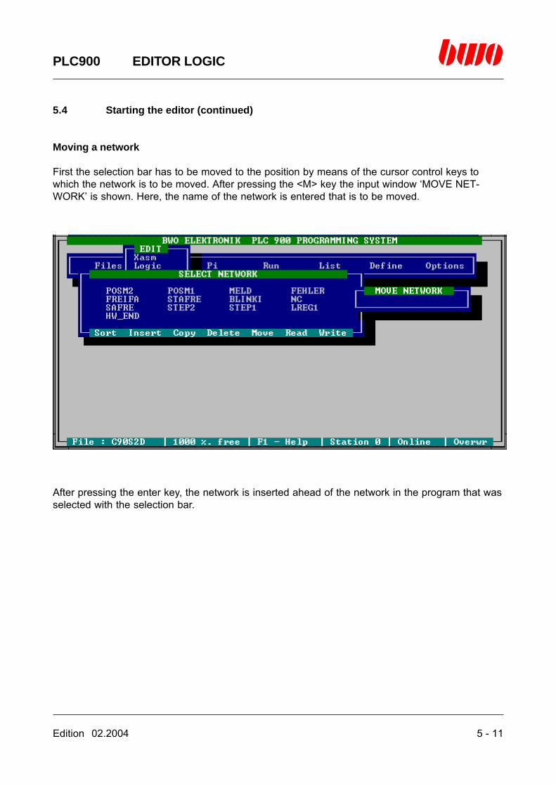
Moving a network
First the selection bar has to be moved to the position by means of the cursor control keys towhich the network is to be moved. After pressing the <M> key the input window ‘MOVE NET-WORK’ is shown. Here, the name of the network is entered that is to be moved.
After pressing the enter key, the network is inserted ahead of the network in the program that wasselected with the selection bar.

5 - 12 Edition 02.2004
PLC900 EDITOR LOGIC
5.4 Starting the editor (continued)
Reading a network from the hard disk
First the selection bar has to be moved to the position by means of the cursor control keys wherethe network is to be inserted. After pressing the <R> key a digest of the network files is displayedwhich are available in the current directory. With the selection bar the desired file can be selectedand read by pressing the enter key. The network is inserted ahead of the network in the programthat was selected by pressing the selection bar in the network digest.
Writing a network on the hard disk
First the network that is to be written on the hard disk has to be selected by means of the cursorcontrol keys. After pressing the <W> key, the network is saved in the file
[network].NW
in the current path, [network] being the name of the network.

Edition 02.2004 5 - 13
PLC900 EDITOR LOGIC
5.5 Editor functions
Editor window
After selecting a network and pressing the enter key, the editor window is shown. The window titledisplays the name of the current network.
There is shown in the first line of the editor window:
- the symbol name, the symbolic address and the comments of the flag or input or outputwhich is located below the cursor
- the length of the network in the assembler- the current cursor position
A newly created network consists of an allocation that can be extended by means of the editor.If the search function has been activated upon starting the editor, the cursor is placed on thesymbol name resp. the symbolic address searched for. With the <CTRL L< key it is possible tocontinue searching in the network.For the purpose of editing, the cursor has to be moved to the valid cursor position and the spacebar has to be pressed. Editing is then performed by means of a menu prompting. You will find thevalid cursor positions in the chapter 6.7.
5 - 14 Edition 02.2004
PLC900 EDITOR LOGIC
5.5 Editor functions (continued)
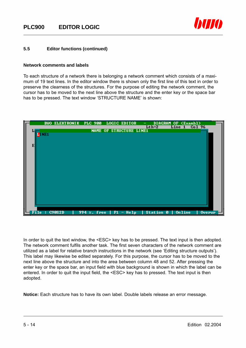
Network comments and labels
To each structure of a network there is belonging a network comment which consists of a maxi-mum of 19 text lines. In the editor window there is shown only the first line of this text in order topreserve the clearness of the structures. For the purpose of editing the network comment, thecursor has to be moved to the next line above the structure and the enter key or the space barhas to be pressed. The text window ‘STRUCTURE NAME’ is shown:
In order to quit the text window, the <ESC> key has to be pressed. The text input is then adopted.The network comment fulfils another task. The first seven characters of the network comment areutilized as a label for relative branch instructions in the network (see ‘Editing structure outputs’).This label may likewise be edited separately. For this purpose, the cursor has to be moved to thenext line above the structure and into the area between column 48 and 52. After pressing theenter key or the space bar, an input field with blue background is shown in which the label can beentered. In order to quit the input field, the <ESC> key has to pressed. The text input is thenadopted.
Notice: Each structure has to have its own label. Double labels release an error message.

Edition 02.2004 5 - 15
PLC900 EDITOR LOGIC
5.5 Editor functions (continued)
Editing structure outputs
A structure output can perform various functions:
Simple Boolean outputThe result of a logical operation is directly or negatedly forwarded to the output. The output isfurnished with a symbolic address or a symbol name as address.
Arithmetical outputThe result of an arithmetical operation is forwarded to the output. The output is furnished with asymbolic address or a symbol name as address.
Set outputA set output is flagged by the letter S in the output symbol. The result of a logical operation isdirectly or negatedly forwarded to the output. If the logical operation is complied with (resp. notcomplied with in case of negation), the output is set to a positive level. The output is furnishedwith a symbolic address or a symbol name as address.
Reset outputA reset output is flagged by the letter R in the output symbol. The result of a logical operation isdirectly or negatedly forwarded to the output. If the logical operation is complied with (resp. notcomplied with in case of negation), the output is set to level zero. The output is furnished with asymbolic address or a symbol name as address.
Jump outputThe result of a logical operation is directly or negatedly forwarded to the output. If the logicaloperation is complied with (resp. not complied with in case of negation), the branch instruction isperformed in the output. The output is furnished with the identification character ‘>>‘ followed by avalid label within the network as address.
Help windows for function blocks
Upon inserting a function block into a network, a question mark can be entered in the selectionwindow ‘NAME OF FUB’ After pressing the enter key, a help window is shown displaying a listingof all function blocks and how they are utilized.

5 - 16 Edition 02.2004
PLC900 EDITOR LOGIC
5.5 Editor functions (continued)
Copying functions
Marking a blockMove the cursor to the output of a box or a function block and press the <CTRL KB> keys. Theblock will have a blue background and the copying functions are activated.
Clearing the marking of a blockPress the <CTRL KH< keys. The marking is cleared and the copying functions are deactivated.
Copying a blockMark the block you want to copy. If you want to insert the marked block as a new structure, pleasemove the cursor to the output of the structure below which the block is to be inserted and pressthe <CTRL KC< keys. The block is inserted and the copying functions are deactivated.If you want to add the marked block to a structure, please move the cursor to the input of thestructure and press the <CTRL KC> keys. The block is inserted and the copying functions aredeactivated.
Moving a blockMark the block you want to move. If you want to insert the marked block as a new structure,please move the cursor to the output of the structure below which the block is to be inserted andpress the <CTRL KV< keys. The block is moved and the copying functions are deactivated.If you want to add the marked block to a structure, please move the cursor to the input of thestructure and press the <CTRL KC> keys. The block is moved and the copying functions aredeactivated.

Edition 02.2004 5 - 17
PLC900 EDITOR LOGIC
5.5 Editor functions (continued)
Quitting the editor
The editor is quitted by pressing the <ESC<key.
If the security inquiry ‘Take over’ is acknowledged with ‘Y’, the editor generates the program codeof the network and inserts it into the PLC program. Upon entering ‘N’ the program is not varied.

5 - 18 Edition 02.2004
PLC900 EDITOR LOGIC
5.6 Compatibility of logic and ladder
The majority of the logic diagrams can be converted without any problems into ladder diagrams.There are, however, structures that are too large for the editor after having converted them in thelogic.
After switching to the logic and attempting to convert, there can be displayed the following mes-sage:

Edition 02.2004 5 - 19
PLC900 EDITOR LOGIC
5.6 Compatibility of logic and ladder (continued)
After switching to the logic and attempting to convert, there can likewise be displayed the follow-ing message:
By showing the messages 4 and 7, the structure is not destroyed. Releasing these errors uninten-tionally does not have any consequences.
The structures have to be separated into smaller units in the ladder by means of intermediateflags and can be represented in the logic.
5 - 20 Edition 02.2004
PLC900 EDITOR LOGIC
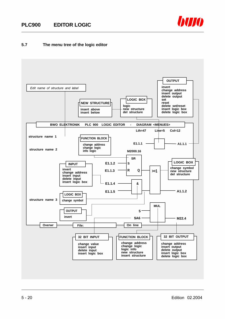
5.7 The menu tree of the logic editor
BWO ELEKTRONIK PLC 900 LOGIC EDITOR - DIAGRAM <MENUES>
Overwr File: On line
Lth=47 Line=5 Col=12
structure name 1
structure name 2
structure name 3
E1.1.1 A1.1.1
>=1
&
SR
MUL
S
R Q
M22.4
A1.1.2
E1.1.2
E1.1.3
E1.1.4
E1.1.5
5
$A6
Edit name of structure and label
OUTPUT
invertchange addressinsert outputdelete outputsetresetdelete set/resetinsert logic boxdelete logic box
LOGIC BOXNEW STRUCTURE
LOGIC BOX
LOGIC BOX
OUTPUT
FUNCTION BLOCK
FUNCTION BLOCK
logicnew structuredel structure
insert aboveinsert below
change symbolnew structuredel structure
change symbol
invert
change addresschange logicinfo logic
change addresschange logiclogic infonew structureinsert structure
INPUT
invertchange addressinsert inputdelete inputinsert logic box
32 BIT OUTPUT32 BIT INPUT
change addressinsert outputdelete outputinsert logic boxdelete logic box
change valueinsert inputdelete inputinsert logic box
M2000.16

Edition 02.2004 5 - 21
PLC900 EDITOR LOGIC
5.8 Valid commands
The following commands can be translated into a logical network:
NOP No operation.
LDL madress Loads an arbitrary memory address with 0 (L).
LDH madress Loads an arbitrary memory address with 1 (H).
LCS (constant) Loads the lower 16 bits of the TOS register with one extended character.The stack pointer is automatically increased.
LCHS (constant) Loads the upper 16 bits of the TOS register.The stack pointer remains unchanged !
LRS madress Loads 4 resp. 2 bytes of the memory of an arbitrary memory address intothe TOS register (32bit resp. 16bit see SIZE).The stack pointer is automatically increased.
LSR madress Loads the TOS register starting from an arbitrary memory address into thememory (4 resp. 2 bytes see SIZE).The stack pointer is automatically decreased.
S Sets an outputR Resets an outputSN Negation of SRN Negation of R
L madress Loads the first operandU madress Logical ANDO madress Logical OR= madress Stores the result
LN madress Negation of LUN madress Negation of UON madress Negation of O=N madress Negation of =
Use of parenthetical expressions:
( , U( , UN( , O( , ON( , N( , )
5 - 22 Edition 02.2004
PLC900 EDITOR LOGIC
5.8 Valid commands (continued)
SPB iadress Jump on condition at IS=1
SPBN iadress Jump on condition at IS=0
BA iadress Like CALL
ISRX Loads the storage cell the address of which is contained in the X register,with the contents of the IS register (IS = internal status)Subsequently, the X register is increased by 1.
DUP Duplicates TOS. TOS = TOS - 1.The stack pointer is automatically increased.
Edition 02.2004 5 - 23
PLC900 EDITOR LOGIC
5.9 Messages
Code Meaning Annotation
01 Invalid number of inputs Maximum of 8 inputs per box
02 Invalid number of inputs Minimum of 1 input in the 1st box
03 Invalid number of inputs Minimum of 2 inputs per box
04 Invalid size of the structure Maximum of 7 levels per structure
05 Invalid number of outputs Maximum of 8 outputs per box
06 Invalid number of outputs Minimum of 1 output per box
07 Structure is too large Graph. Chart > 150 characters
08 Invalid file name File has not been loaded
09 Invalid function block Library of the function block has not been loaded
10 Invalid editor operation Incorrect insertion or deletion
11 Inconsistence of data types Verify data types
12 Unknown command See valid commands
13 Invalid address or value Address or value not according to definition
14 Invalid branch output Branch destination does not exist
15 Structure cannot be represented Logical fault
16 Double label

Edition 02.2004 6 - 1
PLC900 EDITOR LADDER
6. Editor for programming by means of the ladder
6.1 Editor control commands 6 - 2
6.2 Introduction 6 - 3
6.3 Programming networks 6 - 4
6.4 Starting the editor 6 - 7
6.5 Editor functions 6 -13
6.6 Compatibility of logic and ladder 6 -18
6.7 The menu tree of the ladder editor 6 -29
6.8 Valid instructions 6 -30
6.9 Messages 6 -32
⌧
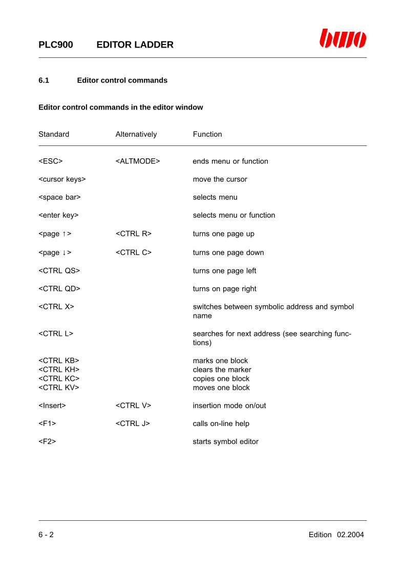
6 - 2 Edition 02.2004
PLC900 EDITOR LADDER
6.1 Editor control commands
Editor control commands in the editor window
Standard Alternatively Function
<ESC> <ALTMODE> ends menu or function
<cursor keys> move the cursor
<space bar> selects menu
<enter key> selects menu or function
<page ↑> <CTRL R> turns one page up
<page ↓> <CTRL C> turns one page down
<CTRL QS> turns one page left
<CTRL QD> turns on page right
<CTRL X> switches between symbolic address and symbolname
<CTRL L> searches for next address (see searching func-tions)
<CTRL KB> marks one block<CTRL KH> clears the marker<CTRL KC> copies one block<CTRL KV> moves one block
<Insert> <CTRL V> insertion mode on/out
<F1> <CTRL J> calls on-line help
<F2> starts symbol editor

Edition 02.2004 6 - 3
PLC900 EDITOR LADDER
6.2 Introduction
Conditions for programming
In order to be able to work with the ladder editor, a PLC nucleus program has to be loaded. Thismay be the BWO adapting program delivered along with or the PLC900 standard library which isin the path \PLC900\LIB and can be opened with the link file LIB900.LNK by way of the function‘FILE/load’. For further information please contact BWO ELEKTRONIK, Dept. ‘Technical Sales’.The nucleus program contains basic structures for networks (network name ‘START’) and statemachines (‘SK1’). Both of these structures must not be deleted!
The following symbol names are pre-defined in the nucleus program:
Symbol name symbolic address function
PWON M33:3 Power-on flags??? M33.6 Auxiliary flags for non-used inputs and outputsLOW M280:11 Low-level flagsHIGH M280:12 High-level flags
Function of a network
A network is a resource for structuring a PLC program. It contains logical operations on inputs,labels and outputs by means of break and make contacts and coils as well as complex functionsthat are realized through so-called function blocks. Networks consist of one or several structureswhich represent a closed linkage each.The ladder editor renders possible to create such networks graphically and to include them in theprogram. Each network is provided with a network name which is inserted as a label in the PLCprogram. The program of a network is linked to this label. The network name consists of a se-quence of six arbitrary characters and may be used in the program only once.

6 - 4 Edition 02.2004
PLC900 EDITOR LADDER
6.3 Programming networks
Format of the symbols
Break contact
Address = symbolic address or symbol nameA maximum of eight break contacts are linked directly serially or directly parallelly
Coil
Address = symbolic address or symbol nameA maximum of eight coils are linked directly parallelly
Address+ +
Address+ +( )

Edition 02.2004 6 - 5
PLC900 EDITOR LADDER
6.3 Programming networks (continued)
Function block
Addr/value = symbolic address, symbol name or constantAddress = symbolic address or symbol nameInputs maximum of 8Outlets maximally 8 parallel steps
You will find further information about function blocks in the chapters C1 and C2.
Symbolic address
Station, local BWONET Example
Flag M[g].[n] M[st].[g].[n] M1.2, M2.4.1
Input E[st].[sl].[e] E[st].[sl].[e] E1.3.17, E2.6.22
Output A[st].[sl].[a] A[st].[sl].[a] A1.1.9, A3.4.11
[g] = Group number (1..3840)[n] = Bit or register number (1..16)[st] = Station number (1..255)[sl] = Slot number (1..32)[e] = Input number (1..32)[a] = Output number (1..32)
Address
(00000)
Address+ +
Address+ +( )
Addr/value E1
E2 A
FUB
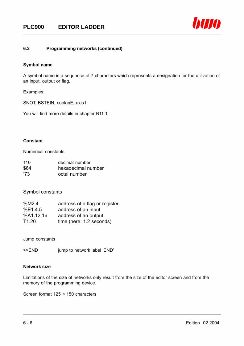
6 - 6 Edition 02.2004
PLC900 EDITOR LADDER
6.3 Programming networks (continued)
Symbol name
A symbol name is a sequence of 7 characters which represents a designation for the utilization ofan input, output or flag.
Examples:
SNOT, BSTEIN, coolanE, axis1
You will find more details in chapter B11.1.
Constant
Numerical constants
110 decimal number$64 hexadecimal number‘73 octal number
Symbol constants
%M2.4 address of a flag or register%E1.4.5 address of an input%A1.12.16 address of an outputT1.20 time (here: 1.2 seconds)
Jump constants
>>END jump to network label ‘END’
Network size
Limitations of the size of networks only result from the size of the editor screen and from thememory of the programming device.
Screen format 125 × 150 characters
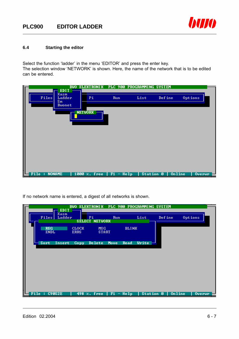
Edition 02.2004 6 - 7
PLC900 EDITOR LADDER
6.4 Starting the editor
Select the function ‘ladder’ in the menu ‘EDITOR’ and press the enter key.The selection window ‘NETWORK’ is shown. Here, the name of the network that is to be editedcan be entered.
If no network name is entered, a digest of all networks is shown.
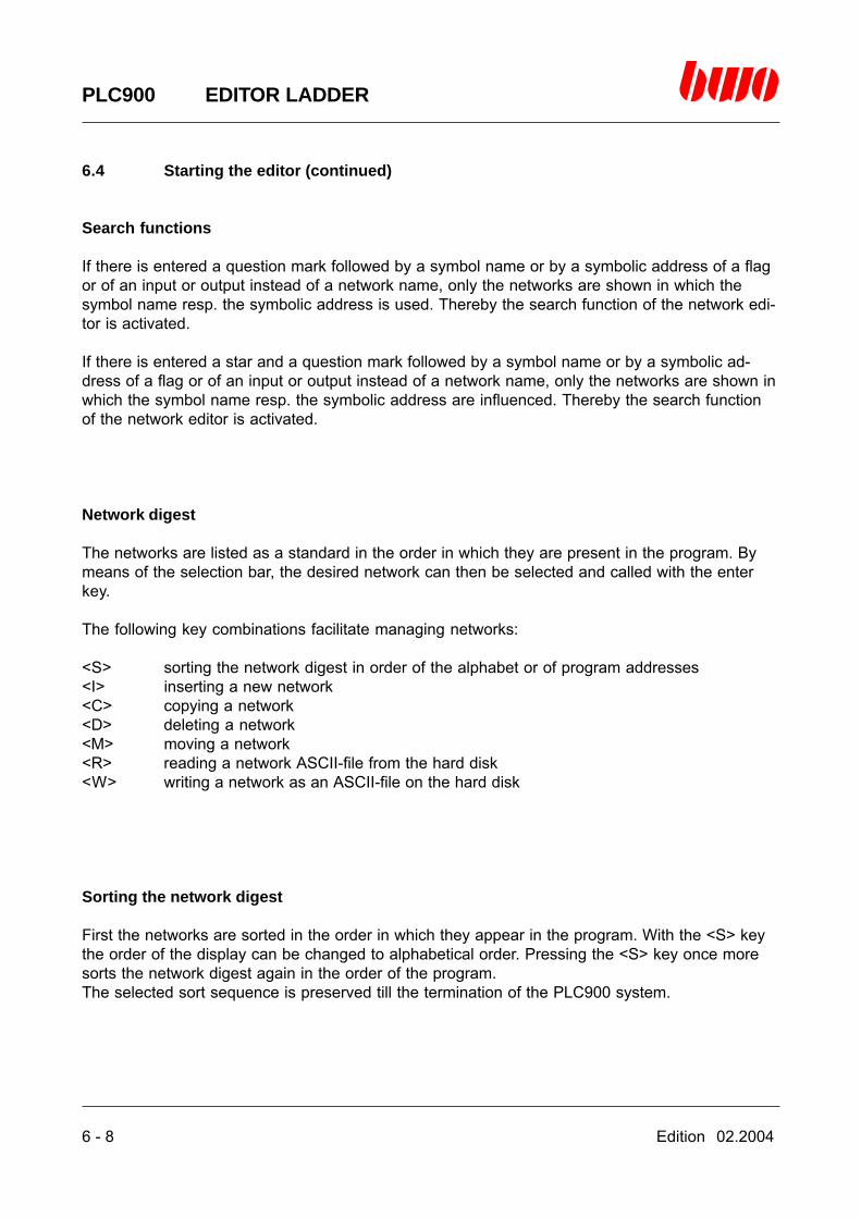
6 - 8 Edition 02.2004
PLC900 EDITOR LADDER
6.4 Starting the editor (continued)
Search functions
If there is entered a question mark followed by a symbol name or by a symbolic address of a flagor of an input or output instead of a network name, only the networks are shown in which thesymbol name resp. the symbolic address is used. Thereby the search function of the network edi-tor is activated.
If there is entered a star and a question mark followed by a symbol name or by a symbolic ad-dress of a flag or of an input or output instead of a network name, only the networks are shown inwhich the symbol name resp. the symbolic address are influenced. Thereby the search functionof the network editor is activated.
Network digest
The networks are listed as a standard in the order in which they are present in the program. Bymeans of the selection bar, the desired network can then be selected and called with the enterkey.
The following key combinations facilitate managing networks:
<S> sorting the network digest in order of the alphabet or of program addresses<I> inserting a new network<C> copying a network<D> deleting a network<M> moving a network<R> reading a network ASCII-file from the hard disk<W> writing a network as an ASCII-file on the hard disk
Sorting the network digest
First the networks are sorted in the order in which they appear in the program. With the <S> keythe order of the display can be changed to alphabetical order. Pressing the <S> key once moresorts the network digest again in the order of the program.The selected sort sequence is preserved till the termination of the PLC900 system.

Edition 02.2004 6 - 9
PLC900 EDITOR LADDER
6.4 Starting the editor (continued)
Inserting a network
First the selection bar has to be moved to the position by means of the cursor control keys wherethe network is to be inserted. After pressing the <I> key the input window ‘NETWORK NAME’ isshown. Here the name of the new network is entered.
After pressing the enter key the network is inserted ahead of the network in the program that wasselected with the selection bar and is then displayed immediately.
Deleting a network
By means of the selection bar the desired file can be selected. After pressing the <D> key thenetwork is deleted.
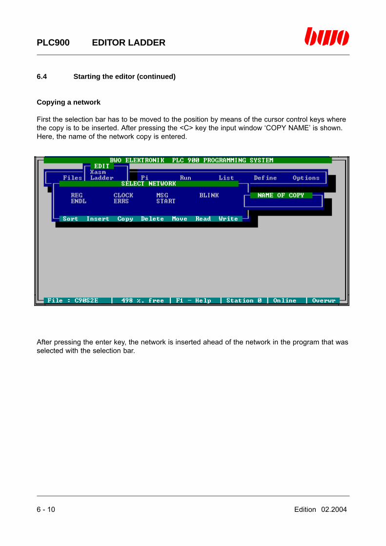
6 - 10 Edition 02.2004
PLC900 EDITOR LADDER
6.4 Starting the editor (continued)
Copying a network
First the selection bar has to be moved to the position by means of the cursor control keys wherethe copy is to be inserted. After pressing the <C> key the input window ‘COPY NAME’ is shown.Here, the name of the network copy is entered.
After pressing the enter key, the network is inserted ahead of the network in the program that wasselected with the selection bar.
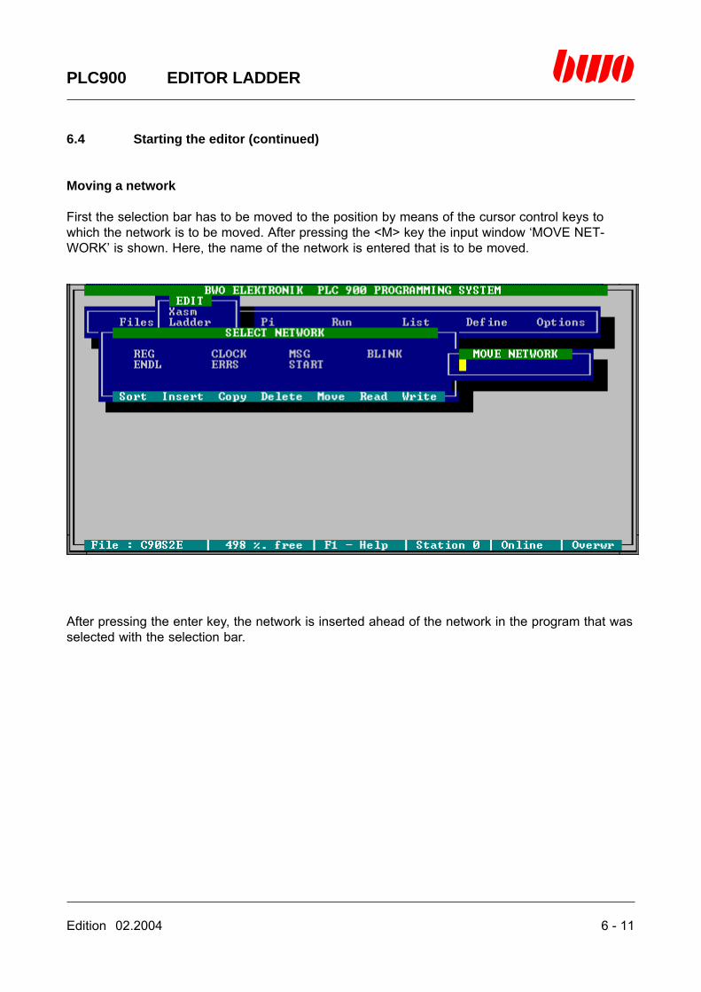
Edition 02.2004 6 - 11
PLC900 EDITOR LADDER
6.4 Starting the editor (continued)
Moving a network
First the selection bar has to be moved to the position by means of the cursor control keys towhich the network is to be moved. After pressing the <M> key the input window ‘MOVE NET-WORK’ is shown. Here, the name of the network is entered that is to be moved.
After pressing the enter key, the network is inserted ahead of the network in the program that wasselected with the selection bar.

6 - 12 Edition 02.2004
PLC900 EDITOR LADDER
6.4 Starting the editor (continued)
Reading a network from the hard disk
First the selection bar has to be moved to the position by means of the cursor control keys wherethe network is to be inserted. After pressing the <R> key a digest of the network files is displayedwhich are available in the current directory. With the selection bar the desired file can be selectedand read with the enter key. The network is inserted ahead of the network in the program that wasselected with the selection bar in the network digest.
Writing a network on the hard disk
First the network that is to be written on the hard disk has to be selected by means of the cursorcontrol keys. After pressing the <W> key, the network is saved in the file
[network].NW
in the current path, [network] being the name of the network.
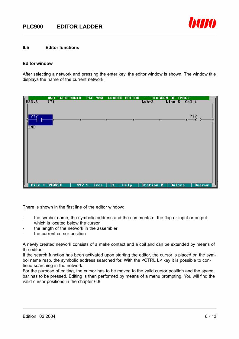
Edition 02.2004 6 - 13
PLC900 EDITOR LADDER
6.5 Editor functions
Editor window
After selecting a network and pressing the enter key, the editor window is shown. The window titledisplays the name of the current network.
There is shown in the first line of the editor window:
- the symbol name, the symbolic address and the comments of the flag or input or outputwhich is located below the cursor
- the length of the network in the assembler- the current cursor position
A newly created network consists of a make contact and a coil and can be extended by means ofthe editor.If the search function has been activated upon starting the editor, the cursor is placed on the sym-bol name resp. the symbolic address searched for. With the <CTRL L< key it is possible to con-tinue searching in the network.For the purpose of editing, the cursor has to be moved to the valid cursor position and the spacebar has to be pressed. Editing is then performed by means of a menu prompting. You will find thevalid cursor positions in the chapter 6.8.
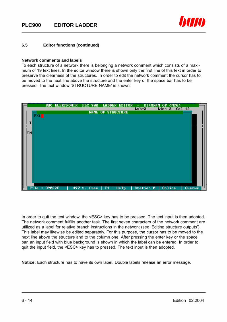
6 - 14 Edition 02.2004
PLC900 EDITOR LADDER
6.5 Editor functions (continued)
Network comments and labelsTo each structure of a network there is belonging a network comment which consists of a maxi-mum of 19 text lines. In the editor window there is shown only the first line of this text in order topreserve the clearness of the structures. In order to edit the network comment the cursor has tobe moved to the next line above the structure and the enter key or the space bar has to bepressed. The text window ‘STRUCTURE NAME’ is shown:
In order to quit the text window, the <ESC> key has to be pressed. The text input is then adopted.The network comment fulfills another task. The first seven characters of the network comment areutilized as a label for relative branch instructions in the network (see ‘Editing structure outputs’).This label may likewise be edited separately. For this purpose, the cursor has to be moved to thenext line above the structure and to the column one. After pressing the enter key or the spacebar, an input field with blue background is shown in which the label can be entered. In order toquit the input field, the <ESC> key has to pressed. The text input is then adopted.
Notice: Each structure has to have its own label. Double labels release an error message.
Edition 02.2004 6 - 15
PLC900 EDITOR LADDER
6.5 Editor functions (continued)
Editing structure outputs
A structure output can perform various functions:
Simple Boolean outputThe result of a logical operation is directly or negatedly forwarded to the output. The output is fur-nished with a symbolic address or a symbol name as address.
Arithmetical outputThe result of an arithmetical operation is forwarded to the output. The output is furnished with asymbolic address or a symbol name as address.
Set outputA set output is flagged by the letter S in the output symbol. The result of a logical operation is di-rectly or negatedly forwarded to the output. If the logical operation is complied with (resp. notcomplied with in case of negation), the output is set to a positive level. The output is furnishedwith a symbolic address or a symbol name as address.
Reset outputA reset output is flagged by the letter R in the output symbol. The result of a logical operation isdirectly or negatedly forwarded to the output. If the logical operation is complied with (resp. notcomplied with in case of negation), the output is set to level zero. The output is furnished with asymbolic address or a symbol name as address.
Jump outputThe result of a logical operation is directly or negatedly forwarded to the output. If the logical op-eration is complied with (resp. not complied with in case of negation), the branch instruction isperformed in the output. The output is furnished with the identification character ‘>>‘ followed by avalid label within the network as address.
Help windows for function blocks
Upon inserting a function block into a network, a question mark can be entered in the selectionwindow ‘FUB NAME’ After pressing the enter key, a help window is shown displaying a listing ofall function blocks and how they are utilzed.

6 - 16 Edition 02.2004
PLC900 EDITOR LADDER
6.5 Editor functions (continued)
Copying functions
Marking a blockMove the cursor to a coil or to a break/make contact or to the output of a function block and pressthe <CTRL KB> keys. The block will have a blue background and the copying functions are acti-vated.
Clearing the marking of a blockPress the <CTRL KH< keys. The marking is cleared and the copying functions are deactivated.
Copying a blockMark the block you want to copy. Move the cursor to the coil of the structure below which theblock is to be inserted and press the <CTRL KC< keys. The block is inserted and the copyingfunctions are deactivated.
Moving a blockMark the block you want to move. Move the cursor to the coil of the structure below which theblock is to be inserted and press the <CTRL KV<keys. The block is moved and the copying func-tions are deactivated.

Edition 02.2004 6 - 17
PLC900 EDITOR LADDER
6.5 Editor functions (continued)
Quitting the editor
The editor is quitted by pressing the <ESC<key.
If the security inquiry ‘Take over’ is acknowledged with ‘Y’, the editor generates the program codeof the network and inserts it into the PLC program. Upon entering ‘N’ the program is not varied.

6 - 18 Edition 02.2004
PLC900 EDITOR LADDER
6.6 Compatibility of logic and ladder
The majority of the logic diagrams can be converted without any problems into ladder diagrams.
There are, however, structures which can only be represented in the ladder after applying thelaws of the Boolean algebra. Both of the symbolic editors of the PLC900 perform this conversionautomatically after being acknowledged by the operator.
This will be explained by means of some examples.
Event 1: Logic boxes with negated outputs
Logic boxes with negated outputs cannot be represented in the ladder. They may, however, besubstituted by using the Boolean algebra without changing the result.
It is held good: (Shannon addition theorem)
(Negation law)
Example:
( A v B ) = ( A B )
A = A
v
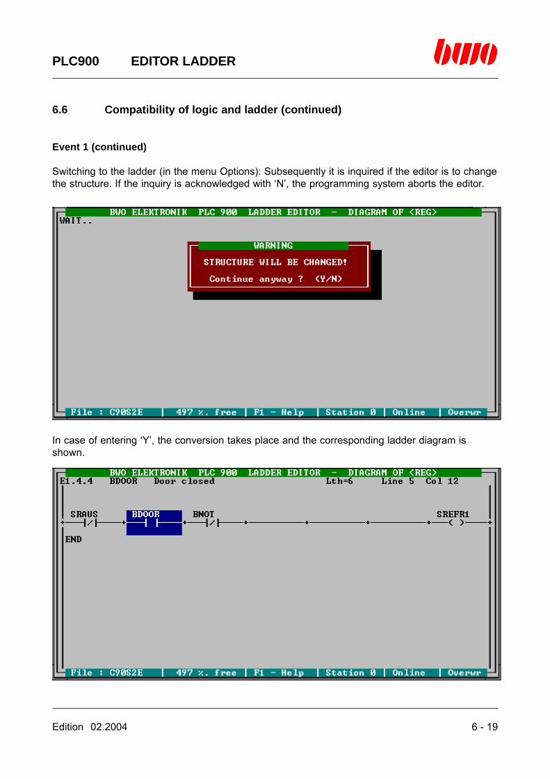
Edition 02.2004 6 - 19
PLC900 EDITOR LADDER
6.6 Compatibility of logic and ladder (continued)
Event 1 (continued)
Switching to the ladder (in the menu Options): Subsequently it is inquired if the editor is to changethe structure. If the inquiry is acknowledged with ‘N’, the programming system aborts the editor.
In case of entering ‘Y’, the conversion takes place and the corresponding ladder diagram isshown.
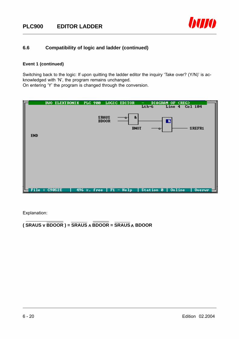
6 - 20 Edition 02.2004
PLC900 EDITOR LADDER
6.6 Compatibility of logic and ladder (continued)
Event 1 (continued)
Switching back to the logic: If upon quitting the ladder editor the inquiry ‘Take over? (Y/N)’ is ac-knowledged with ‘N’, the program remains unchanged.On entering ‘Y’ the program is changed through the conversion.
Explanation:
v( SRAUS v BDOOR ) = SRAUS BDOOR = SRAUS BDOOR v

Edition 02.2004 6 - 21
PLC900 EDITOR LADDER
6.6 Compatibility of logic and ladder (continued)
Event 2 AND-operations on one function block
AND-operations on blocks and other logic boxes can be realized in the ladder if they are a firstelement in the operation. According to the rules of the Boolean algebra it is possible to invert sim-ple AND-operations.
It is held good: (Commutative principle)
(Commutative principle)
Example:
v
v
v( A v B ) C = C ( A v B )
( A B ) v C = C v ( A B )v
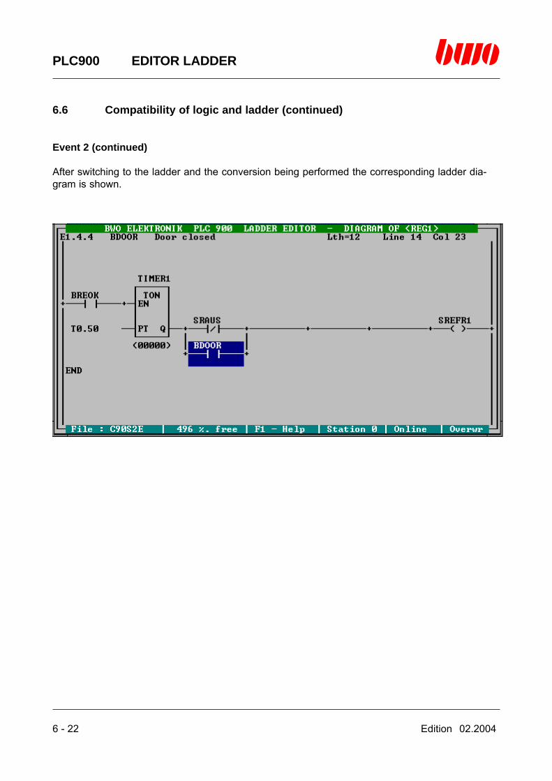
6 - 22 Edition 02.2004
PLC900 EDITOR LADDER
6.6 Compatibility of logic and ladder (continued)
Event 2 (continued)
After switching to the ladder and the conversion being performed the corresponding ladder dia-gram is shown.

Edition 02.2004 6 - 23
PLC900 EDITOR LADDER
6.6 Compatibility of logic and ladder (continued)
Event 2 (continued)
If the conversion is saved in a backup file and switching to the logic is performed the followinglogic diagram is then shown.
Explanation:
v
( SRAUS v BDOOR ) TON [ BREOK, T0.50 ]
= TON [ BREOK, T0.50 ] ( SRAUS v BDOOR )
v
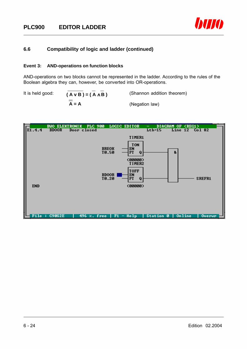
6 - 24 Edition 02.2004
PLC900 EDITOR LADDER
6.6 Compatibility of logic and ladder (continued)
Event 3: AND-operations on function blocks
AND-operations on two blocks cannot be represented in the ladder. According to the rules of theBoolean algebra they can, however, be converted into OR-operations.
It is held good: (Shannon addition theorem)
(Negation law)
( A v B ) = ( A B )
A = A
v

Edition 02.2004 6 - 25
PLC900 EDITOR LADDER
6.6 Compatibility of logic and ladder (continued)
Event 3 (continued)
After switching to the ladder and the conversion being performed the corresponding ladder dia-gram is shown.

6 - 26 Edition 02.2004
PLC900 EDITOR LADDER
6.6 Compatibility of logic and ladder (continued)
Event 3 (continued)
If the conversion is saved in a backup file and switching to the logic is performed the followinglogic diagram is then shown.
Explanation:
Definition:
v
FUB1 = TOFF [ BDOOR, T0.20 ]
FUB2 = TON [BREOK, T0.50 ]
FUB1 FUB2 = ( FUB1 FUB2 ) = ( FUB1 v FUB2 )v

Edition 02.2004 6 - 27
PLC900 EDITOR LADDER
6.6 Compatibility of logic and ladder (continued)
Special events
Besides the structures mentioned so far there are existing another two types of operations whichcannot be converted into a ladder diagram even on applying the rules of the Boolean algebra:
- AND-operation on two blocks on the second and on each further level of a structure- Indirect AND operation on two blocks.
Event 4: AND-operation on two blocks on the second and on each further level of a struc-ture
After switching to the ladder and trying to convert the following message will be shown:

6 - 28 Edition 02.2004
PLC900 EDITOR LADDER
6.6 Compatibility of logic and ladder (continued)
Event 5: Indirect AND-operation on two blocks
After switching to the ladder and trying to convert the following message will be shown:
By the message 27 (Structure cannot be represented) being shown, the structure will not be de-stroyed. Releasing this message unintentionally will have no consequences.
The structures listed under event 4 and 5 can be represented in the ladder, too, but only by usingintermediate flags.
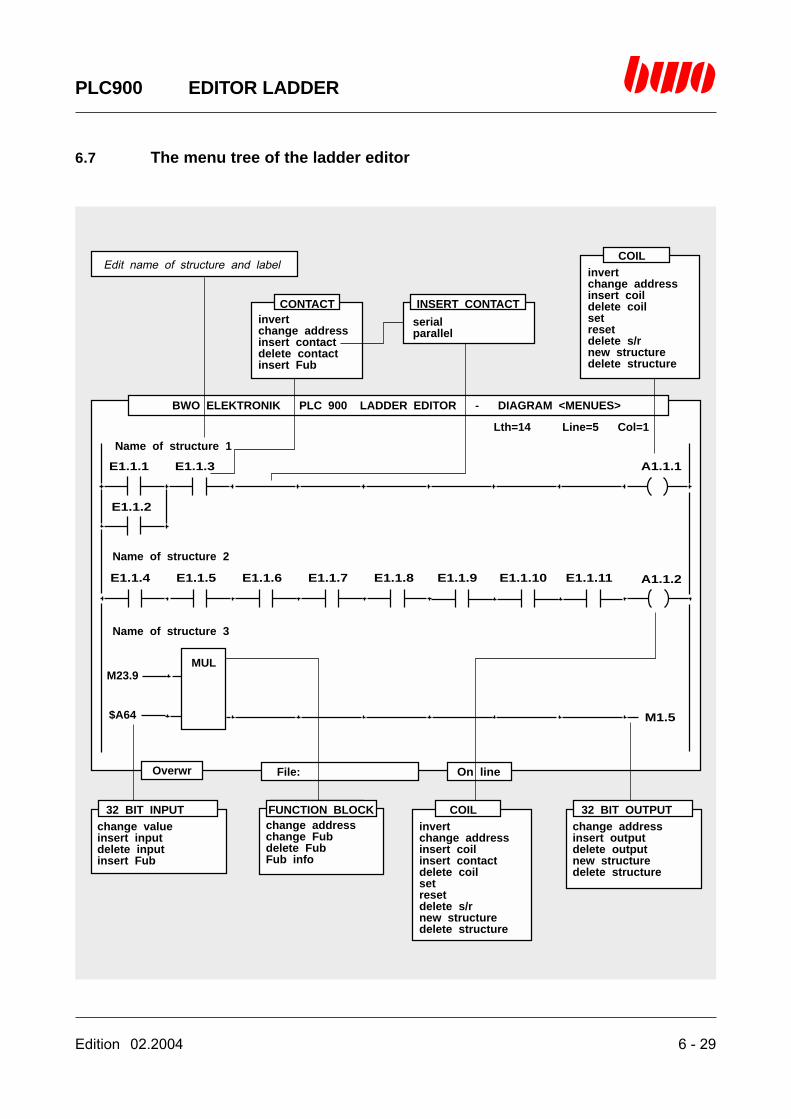
Edition 02.2004 6 - 29
PLC900 EDITOR LADDER
6.7 The menu tree of the ladder editor
BWO ELEKTRONIK PLC 900 LADDER EDITOR - DIAGRAM <MENUES>
Overwr File: On line
Lth=14 Line=5 Col=1
E1.1.1
E1.1.4
E1.1.2
E1.1.3
E1.1.5 E1.1.7 E1.1.10E1.1.6 E1.1.9E1.1.8 E1.1.11
A1.1.1
M1.5
A1.1.2
Name of structure 1
Name of structure 2
Name of structure 3
$A64
M23.9MUL
invertchange addressinsert contactdelete contactinsert Fub
change addresschange Fubdelete FubFub info
serialparallel
invertchange addressinsert coilinsert contactdelete coilsetresetdelete s/rnew structuredelete structure
invertchange addressinsert coildelete coilsetresetdelete s/rnew structuredelete structure
change addressinsert outputdelete outputnew structuredelete structure
change valueinsert inputdelete inputinsert Fub
CONTACT
FUNCTION BLOCK
INSERT CONTACT
COIL
COIL
32 BIT OUTPUT32 BIT INPUT
Edit name of structure and label
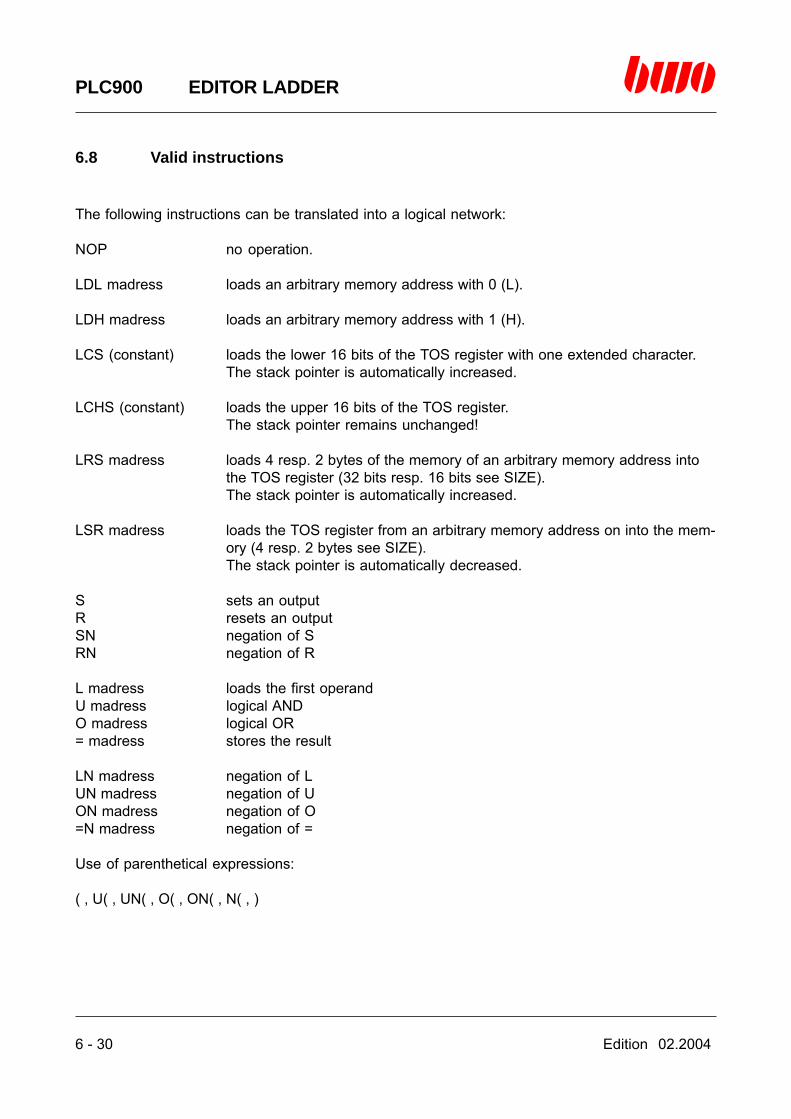
6 - 30 Edition 02.2004
PLC900 EDITOR LADDER
6.8 Valid instructions
The following instructions can be translated into a logical network:
NOP no operation.
LDL madress loads an arbitrary memory address with 0 (L).
LDH madress loads an arbitrary memory address with 1 (H).
LCS (constant) loads the lower 16 bits of the TOS register with one extended character.The stack pointer is automatically increased.
LCHS (constant) loads the upper 16 bits of the TOS register.The stack pointer remains unchanged!
LRS madress loads 4 resp. 2 bytes of the memory of an arbitrary memory address intothe TOS register (32 bits resp. 16 bits see SIZE).The stack pointer is automatically increased.
LSR madress loads the TOS register from an arbitrary memory address on into the mem-ory (4 resp. 2 bytes see SIZE).The stack pointer is automatically decreased.
S sets an outputR resets an outputSN negation of SRN negation of R
L madress loads the first operandU madress logical ANDO madress logical OR= madress stores the result
LN madress negation of LUN madress negation of UON madress negation of O=N madress negation of =
Use of parenthetical expressions:
( , U( , UN( , O( , ON( , N( , )
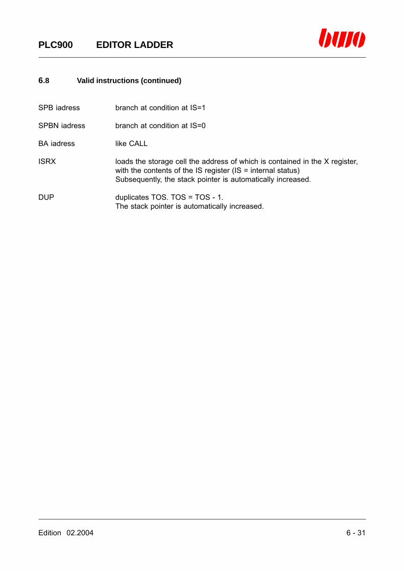
Edition 02.2004 6 - 31
PLC900 EDITOR LADDER
6.8 Valid instructions (continued)
SPB iadress branch at condition at IS=1
SPBN iadress branch at condition at IS=0
BA iadress like CALL
ISRX loads the storage cell the address of which is contained in the X register,with the contents of the IS register (IS = internal status)Subsequently, the stack pointer is automatically increased.
DUP duplicates TOS. TOS = TOS - 1.The stack pointer is automatically increased.
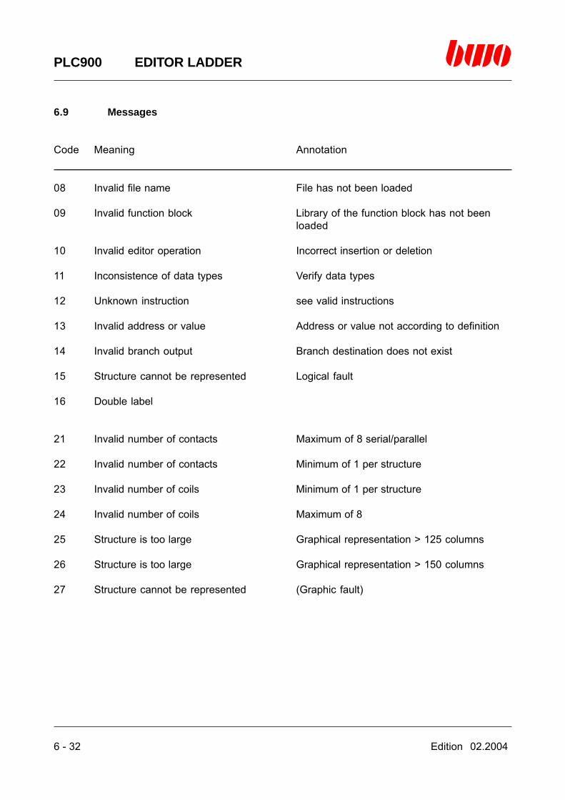
6 - 32 Edition 02.2004
PLC900 EDITOR LADDER
6.9 Messages
Code Meaning Annotation
08 Invalid file name File has not been loaded
09 Invalid function block Library of the function block has not beenloaded
10 Invalid editor operation Incorrect insertion or deletion
11 Inconsistence of data types Verify data types
12 Unknown instruction see valid instructions
13 Invalid address or value Address or value not according to definition
14 Invalid branch output Branch destination does not exist
15 Structure cannot be represented Logical fault
16 Double label
21 Invalid number of contacts Maximum of 8 serial/parallel
22 Invalid number of contacts Minimum of 1 per structure
23 Invalid number of coils Minimum of 1 per structure
24 Invalid number of coils Maximum of 8
25 Structure is too large Graphical representation > 125 columns
26 Structure is too large Graphical representation > 150 columns
27 Structure cannot be represented (Graphic fault)

Edition 02.2004 7 - 1
PLC900 EDITOR STATE MACHINES (SM)
7. Editor for programming by means of state machines
7.1 Editor control commands 7 - 2
7.2 Introduction 7 - 3
7.3 Programming state machines 7 - 5
7.4 Flow of a state machine 7 -12
7.5 Starting the editor 7 -14
7.6 Editor functions 7 -19
7.7 The menu tree of the state machine editor 7 -26
7.8 Valid commands 7 -27
7.9 Messages 7 -29
⌧
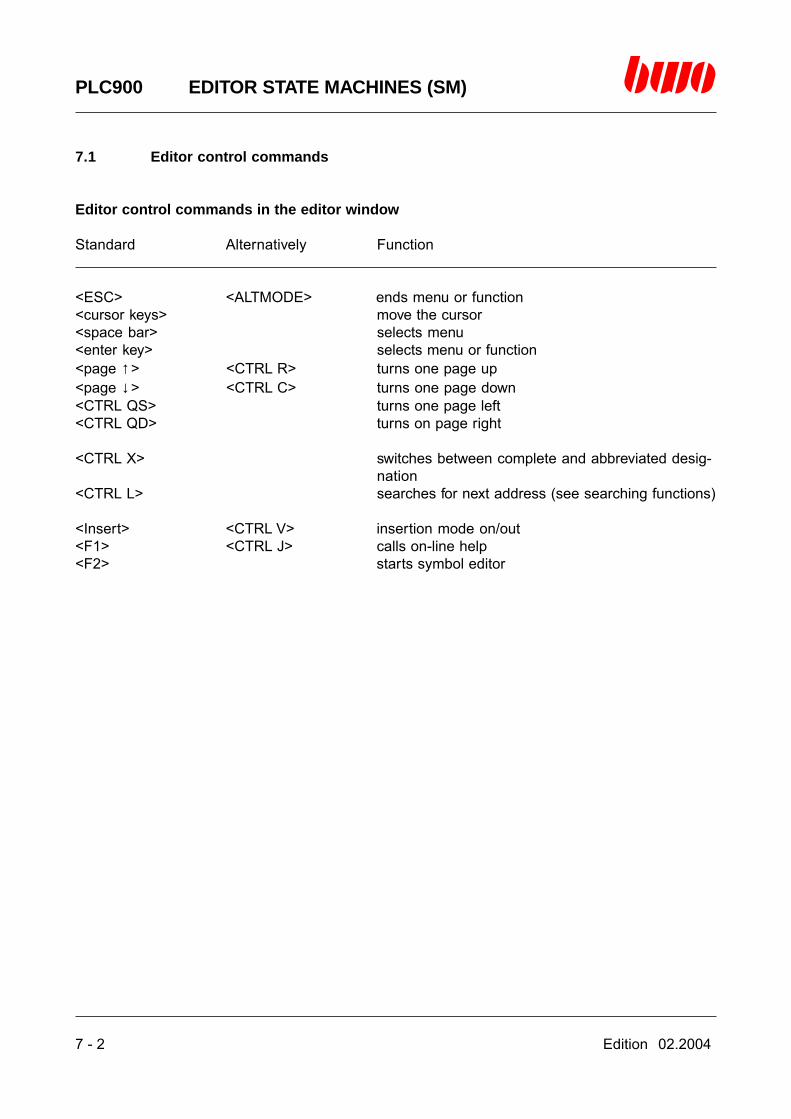
7 - 2 Edition 02.2004
PLC900 EDITOR STATE MACHINES (SM)
7.1 Editor control commands
Editor control commands in the editor window
Standard Alternatively Function
<ESC> <ALTMODE> ends menu or function<cursor keys> move the cursor<space bar> selects menu<enter key> selects menu or function<page ↑> <CTRL R> turns one page up<page ↓> <CTRL C> turns one page down<CTRL QS> turns one page left<CTRL QD> turns on page right
<CTRL X> switches between complete and abbreviated desig-nation
<CTRL L> searches for next address (see searching functions)
<Insert> <CTRL V> insertion mode on/out<F1> <CTRL J> calls on-line help<F2> starts symbol editor

Edition 02.2004 7 - 3
PLC900 EDITOR STATE MACHINES (SM)
7.2 Introduction
Conditions for programming
In order to be able to work with the state machine editor Sm, it is necessary to load first of all aPLC nucleus program. This may be the BWO adapting program delivered along with or thePLC900 standard library which is in the path \PLC900\LIB and can be opened with the link fileLIB900.LNK by way of the function ‘FILE/load’. For further information please contact BWOELEKTRONIK, Dept. ‘Technical Sales’.The nucleus program contains basic structures for networks (network name ‘START’) and statemachines (‘SK1’). Both of these structures must not be deleted!
The following symbol names are pre-defined in the nucleus program:
Symbol name symbolic address function
PWON M33:3 Power-on flags??? M33.6 Auxiliary flags for non-used inputs and outputsLOW M280:11 Low-level flagsHIGH M280:12 High-level flags
SK_LOE∧ M252.16 State machines deleting flagS_AKTIV M253.2 Step flag
SK1 M259.1 First flag of a data field of the state machine ‘SK1’.The following 32 flags contain the internal data ofthe state machine.
_SKEND M261.1 End of the state machine data. This symbol namehas to be placed behind the last flag of the datafield of the last state machine.
The symbolic addresses S_AKTIV, SK_LOE∧ and the flag area between the flags SK1 and_SKEND are necessary for controlling the state machines. While S_AKTIV and SK_LOE∧ arecommonly used by all state machines, it is required for generating a new state machine to createa further data field with 32 flags for the state machine data each time. The detailed procedure isexpounded in the description of the state machine function blocks SKOB and SKOB2.
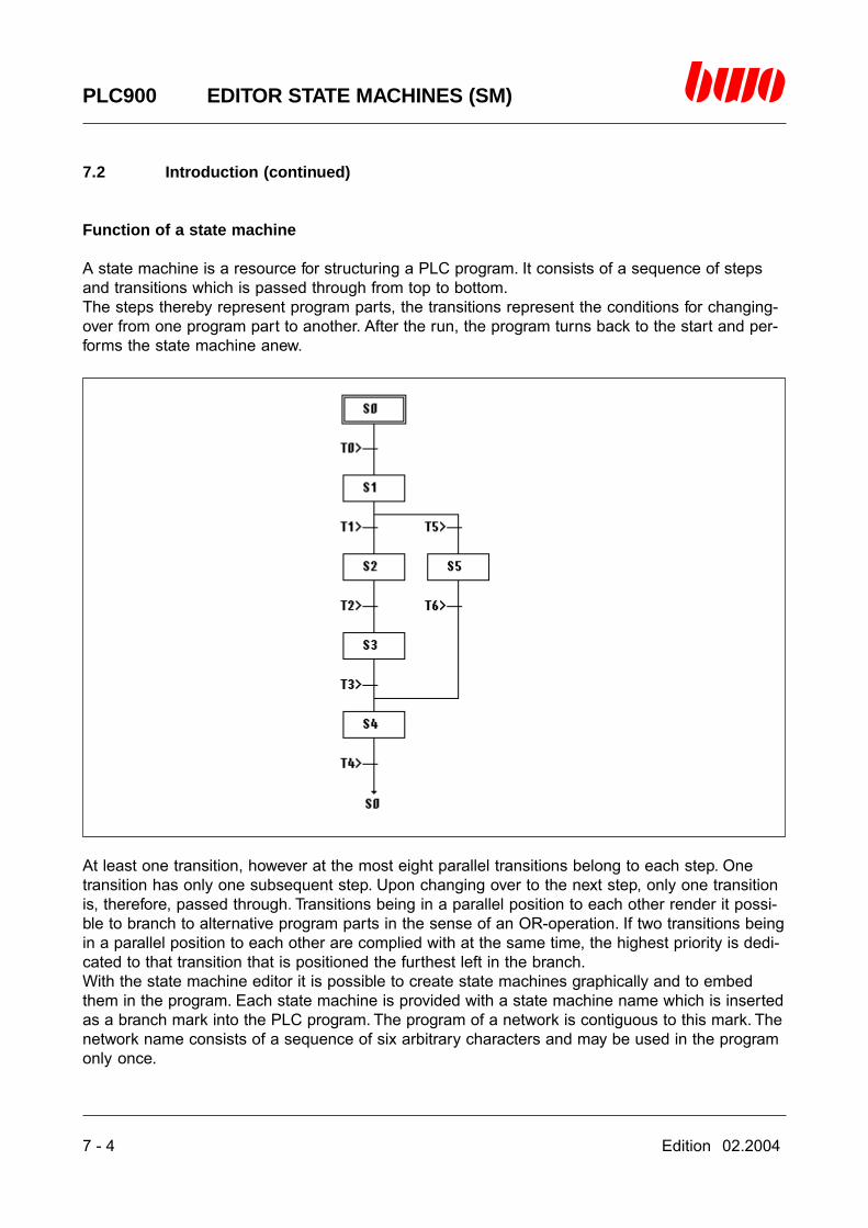
7 - 4 Edition 02.2004
PLC900 EDITOR STATE MACHINES (SM)
7.2 Introduction (continued)
Function of a state machine
A state machine is a resource for structuring a PLC program. It consists of a sequence of stepsand transitions which is passed through from top to bottom.The steps thereby represent program parts, the transitions represent the conditions for changing-over from one program part to another. After the run, the program turns back to the start and per-forms the state machine anew.
At least one transition, however at the most eight parallel transitions belong to each step. Onetransition has only one subsequent step. Upon changing over to the next step, only one transitionis, therefore, passed through. Transitions being in a parallel position to each other render it possi-ble to branch to alternative program parts in the sense of an OR-operation. If two transitions beingin a parallel position to each other are complied with at the same time, the highest priority is dedi-cated to that transition that is positioned the furthest left in the branch.With the state machine editor it is possible to create state machines graphically and to embedthem in the program. Each state machine is provided with a state machine name which is insertedas a branch mark into the PLC program. The program of a network is contiguous to this mark. Thenetwork name consists of a sequence of six arbitrary characters and may be used in the programonly once.
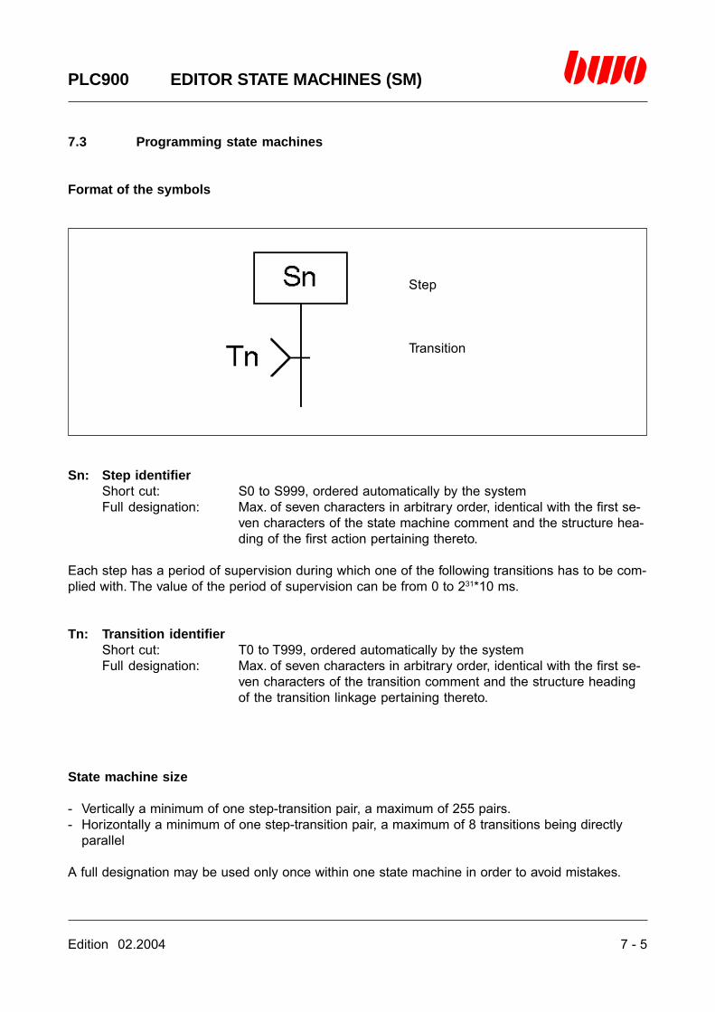
Edition 02.2004 7 - 5
PLC900 EDITOR STATE MACHINES (SM)
7.3 Programming state machines
Format of the symbols
Step
Transition
Sn: Step identifierShort cut: S0 to S999, ordered automatically by the systemFull designation: Max. of seven characters in arbitrary order, identical with the first se-
ven characters of the state machine comment and the structure hea-ding of the first action pertaining thereto.
Each step has a period of supervision during which one of the following transitions has to be com-plied with. The value of the period of supervision can be from 0 to 231*10 ms.
Tn: Transition identifierShort cut: T0 to T999, ordered automatically by the systemFull designation: Max. of seven characters in arbitrary order, identical with the first se-
ven characters of the transition comment and the structure headingof the transition linkage pertaining thereto.
State machine size
- Vertically a minimum of one step-transition pair, a maximum of 255 pairs.- Horizontally a minimum of one step-transition pair, a maximum of 8 transitions being directly
parallel
A full designation may be used only once within one state machine in order to avoid mistakes.
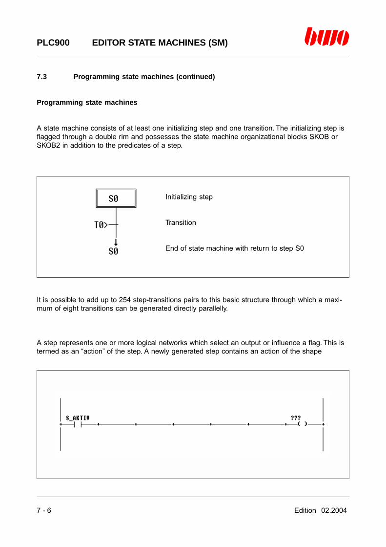
7 - 6 Edition 02.2004
PLC900 EDITOR STATE MACHINES (SM)
7.3 Programming state machines (continued)
Programming state machines
A state machine consists of at least one initializing step and one transition. The initializing step isflagged through a double rim and possesses the state machine organizational blocks SKOB orSKOB2 in addition to the predicates of a step.
Initializing step
Transition
End of state machine with return to step S0
It is possible to add up to 254 step-transitions pairs to this basic structure through which a maxi-mum of eight transitions can be generated directly parallelly.
A step represents one or more logical networks which select an output or influence a flag. This istermed as an “action” of the step. A newly generated step contains an action of the shape

Edition 02.2004 7 - 7
PLC900 EDITOR STATE MACHINES (SM)
7.3 Programming state machines (continued)
A transition represents the condition for continuing the state machine onto the next step.A newly generated transition contains the condition for continuing of the shape
The action of the step is performed as long as the flag S_AKTIV has a positive level. As soon asS_AKTIV decreases to level zero all of the outputs and flags linked to S_AKTIV are brought tolevel zero. The state of the flag S_AKTIV is influenced by the transitions which are subsequent tothe step and the states of the inputs of the block SKOB resp. SKOB2.

7 - 8 Edition 02.2004
PLC900 EDITOR STATE MACHINES (SM)
7.3 Programming state machines (continued)
State machine organizational block SKOB
The State machine organizational block SKOB is used in state machines which have been cre-ated by means of a PLC900, version 1, or of the programming system PLC500. It controls the flowof the state machine by switching an internal step counter. The parameterization of the block hasto be done by the user as follows:
Ski: Local data field of the block, flag with symbol nameLike every block containing local data, the organizational block requires a flag area inwhich it can administrate its data. In the menu ‘Symbols’ there has to be inserted afield of 32 flags ahead of the flag upon creating a new state machine. The first flag hasto be provided with a symbol name that corresponds to the name of the new statemachine. By registering this flag in the block, the required co-ordination of the datafield is carried out.
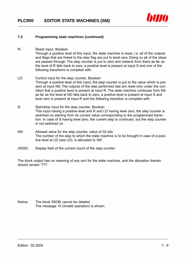
Edition 02.2004 7 - 9
PLC900 EDITOR STATE MACHINES (SM)
7.3 Programming state machines (continued)
R: Reset input, BooleanThrough a positive level of this input, the state machine is reset, i.e. all of the outputsand flags that are linked to the step flag are put to level zero. Doing so all of the stepsare passed through. The step counter is put to zero and restarts from there as far asthe level of R falls back to zero, a positive level is present at input S and one of thefollowing transitions is complied with.
LD: Control input for the step counter, BooleanThrough a positive level of this input, the step counter is put to the value which is pre-sent at input NS. The outputs of the step performed last are reset only under the con-dition that a positive level is present at input R. The state machine continues from NSas far as the level at ND falls back to zero, a positive level is present at input S andlevel zero is present at input R and the following transition is complied with.
S: Start/stop input for the step counter, BooleanThis input having a positive level and R and LD having level zero, the step counter isswitched on starting from its current value corresponding to the programmed transi-tion. In case of S having level zero, the current step is continued, but the step counteris not switched on.
NS: Allowed value for the step counter, value of 32 bitsThe number of the step to which the state machine is to be brought in case of a posi-tive level at LD (see LD), is allocated to ‘NS’.
(0000): Display field of the current count of the step counter
The block output has no meaning of any sort for the state machine, and the allocation theretoshould remain ‘???’
Notice: The block SKOB cannot be deleted.The message 10 (Invalid operation) is shown.

7 - 10 Edition 02.2004
PLC900 EDITOR STATE MACHINES (SM)
7.3 Programming state machines (continued)
State machine organizational block SKOB2
The State machine organizational block SKOB2 is used in state machines which have beencreated by means of the PLC900, version 2.0. It controls the flow of the state machine by switch-ing an internal step counter. SKOB2 allows a step-by-step procedure for the flow of a state ma-chine contrary to the block SKOB. The parameterization of the block has to be done by the useras follows:
Ski: Local data field of the block, flag with symbol nameLike every block containing local data, the organizational block requires a flag area inwhich it can administrate its data. In the menu ‘Symbols’ there has to be inserted afield of 32 flags ahead of the flag upon creating a new state machine. The first flag hasto be provided with a symbol name that corresponds to the name of the new statemachine. By registering this flag in the block, the required co-ordination of the datafield is carried out.
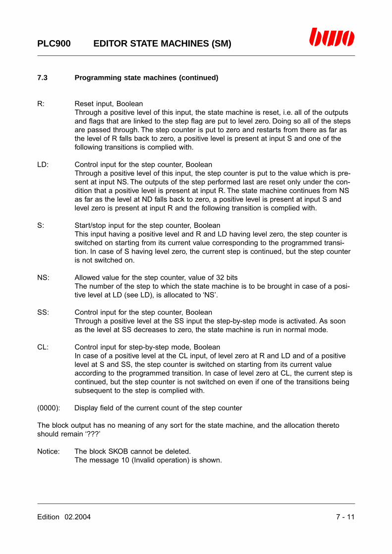
Edition 02.2004 7 - 11
PLC900 EDITOR STATE MACHINES (SM)
7.3 Programming state machines (continued)
R: Reset input, BooleanThrough a positive level of this input, the state machine is reset, i.e. all of the outputsand flags that are linked to the step flag are put to level zero. Doing so all of the stepsare passed through. The step counter is put to zero and restarts from there as far asthe level of R falls back to zero, a positive level is present at input S and one of thefollowing transitions is complied with.
LD: Control input for the step counter, BooleanThrough a positive level of this input, the step counter is put to the value which is pre-sent at input NS. The outputs of the step performed last are reset only under the con-dition that a positive level is present at input R. The state machine continues from NSas far as the level at ND falls back to zero, a positive level is present at input S andlevel zero is present at input R and the following transition is complied with.
S: Start/stop input for the step counter, BooleanThis input having a positive level and R and LD having level zero, the step counter isswitched on starting from its current value corresponding to the programmed transi-tion. In case of S having level zero, the current step is continued, but the step counteris not switched on.
NS: Allowed value for the step counter, value of 32 bitsThe number of the step to which the state machine is to be brought in case of a posi-tive level at LD (see LD), is allocated to ‘NS’.
SS: Control input for the step counter, BooleanThrough a positive level at the SS input the step-by-step mode is activated. As soonas the level at SS decreases to zero, the state machine is run in normal mode.
CL: Control input for step-by-step mode, BooleanIn case of a positive level at the CL input, of level zero at R and LD and of a positivelevel at S and SS, the step counter is switched on starting from its current valueaccording to the programmed transition. In case of level zero at CL, the current step iscontinued, but the step counter is not switched on even if one of the transitions beingsubsequent to the step is complied with.
(0000): Display field of the current count of the step counter
The block output has no meaning of any sort for the state machine, and the allocation theretoshould remain ‘???’
Notice: The block SKOB cannot be deleted.The message 10 (Invalid operation) is shown.

7 - 12 Edition 02.2004
PLC900 EDITOR STATE MACHINES (SM)
7.4 Flow of a state machine
The behaviour of a state machine depends upon the programming of steps and transitions as wellas of the parameterization of the State machine organizational blocks SKOB resp. SKOB2. In asingle run of the program, the block SKOB resp. SKOB2, the current step and the transitions sub-sequent thereto are passed through. All of the remaining steps and transitions of the state ma-chine are skipped.
First the state machine has to be brought to a defined basic state by means of the block SKOBresp. SKOB2. For this purpose the state machine is stopped, i.e. switching it on to the next step issuppressed (input S). Thereafter, all of the outputs and flags that are used in the state machineand that are linked to the step flag S_AKTIV, are put to level zero, and the state machine is setonto the step zero (input R). If the state machine is to start from another step, the state machinecan subsequently be set onto another step (inputs NS and LD).
When the state machine is started (inputs S, R and LD), the transitions being subsequent to thestep are evaluated in the next program run. If no transition is complied with, the step flag S_AKTIVis put to a positive level and the actions of the step are performed. If one of the transitions iscomplied with, the step flag S_AKTIV is put to level zero. The actions of the step that are linked toS_AKTIV are not performed, and the block SKOB switches to the corresponding following step.When using the state machine block SKOB2 it is additionally required the presence of a positivelevel at the input CL in order that the state machine switches to the next step. In the next programrun this procedure is repeated with the next step.
In particular cases, using the step flag S_AKTIV can influence the program run in an unintentionalmanner.
The transition Tn is not complied with, the transition Tn+1 is complied with. Step Sn is not passedthrough. If the transition Tn is complied with, the testing for the validity of Tn+1 is carried out.Since Tn+1 is complied with, S_AKTIV remains on level zero. Sn is passed through, but the ac-tions of Sn are not performed as they are linked to S_AKTIV. The state machine makes believe tohave processed the step. In fact, none of the actions has been carried out.

Edition 02.2004 7 - 13
PLC900 EDITOR STATE MACHINES (SM)
7.4 Flow of a state machine (continued)
The program may be corrected by linking the actions of the step not to S_AKTIV so that they areperformed always independently of the state of the subsequent transitions when the step ispassed through.Doing so, it has to be taken in mind that in such case the outputs and flags are no longer broughtto level zero upon resetting the state machine in the block SKOB resp. SKOB2. For this purpose,the deleting flag SK_LOE∧ has to be used then. SK_LOE∧ is put to a positive level with a positivelevel being present at the block input R and can lead to putting the outputs and flags to level zerothrough a corresponding linkage.
The state machine is edited by the user in steps and transitions as well as in the state machineorganizational block SKOB resp. SKOB2 by means of the magnifier function in the ladder of thelogic. In order to prevent undefined states of the state machine brought about by the flag ‘???’ (that is used in each basic structure as a variable), al of the transitions and steps have to be ed-ited.
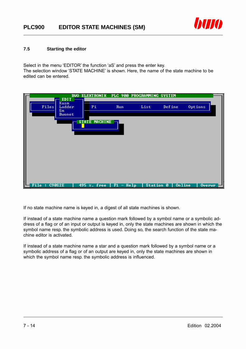
7 - 14 Edition 02.2004
PLC900 EDITOR STATE MACHINES (SM)
7.5 Starting the editor
Select in the menu ‘EDITOR’ the function ‘aS’ and press the enter key.The selection window ‘STATE MACHINE’ is shown. Here, the name of the state machine to beedited can be entered.
If no state machine name is keyed in, a digest of all state machines is shown.
If instead of a state machine name a question mark followed by a symbol name or a symbolic ad-dress of a flag or of an input or output is keyed in, only the state machines are shown in which thesymbol name resp. the symbolic address is used. Doing so, the search function of the state ma-chine editor is activated.
If instead of a state machine name a star and a question mark followed by a symbol name or asymbolic address of a flag or of an output are keyed in, only the state machines are shown inwhich the symbol name resp. the symbolic address is influenced.
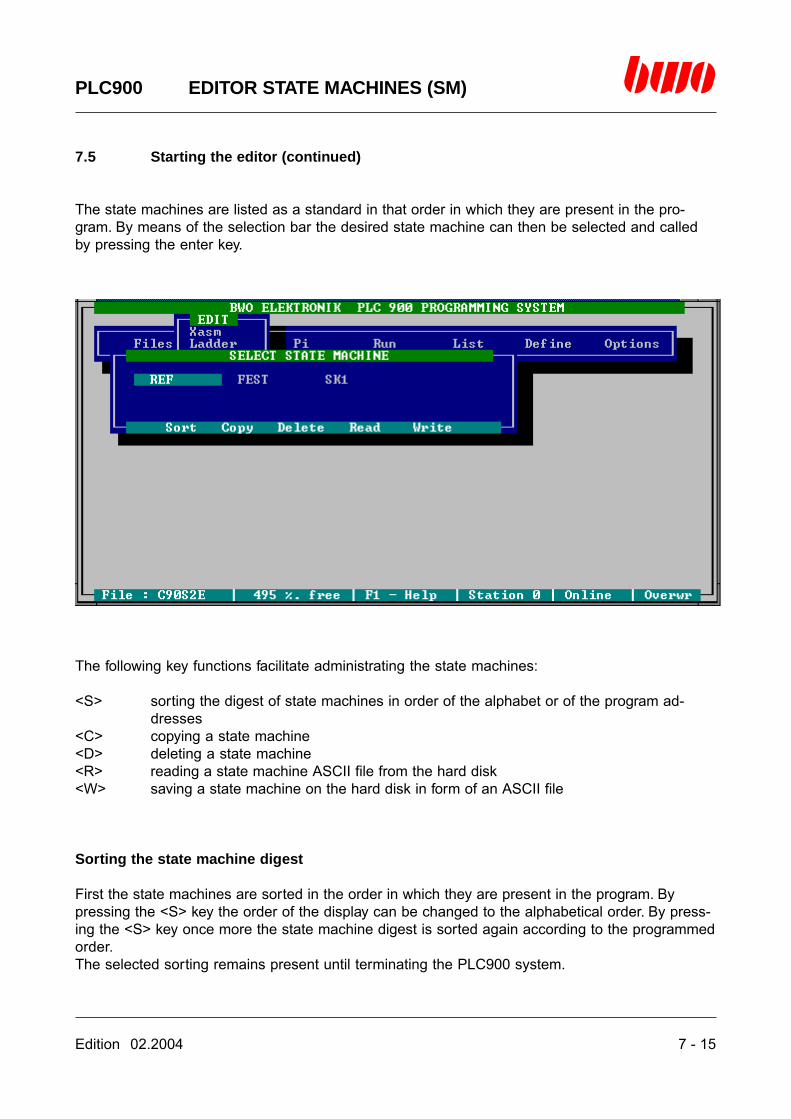
Edition 02.2004 7 - 15
PLC900 EDITOR STATE MACHINES (SM)
7.5 Starting the editor (continued)
The state machines are listed as a standard in that order in which they are present in the pro-gram. By means of the selection bar the desired state machine can then be selected and calledby pressing the enter key.
The following key functions facilitate administrating the state machines:
<S> sorting the digest of state machines in order of the alphabet or of the program ad-dresses
<C> copying a state machine<D> deleting a state machine<R> reading a state machine ASCII file from the hard disk<W> saving a state machine on the hard disk in form of an ASCII file
Sorting the state machine digest
First the state machines are sorted in the order in which they are present in the program. Bypressing the <S> key the order of the display can be changed to the alphabetical order. By press-ing the <S> key once more the state machine digest is sorted again according to the programmedorder.The selected sorting remains present until terminating the PLC900 system.
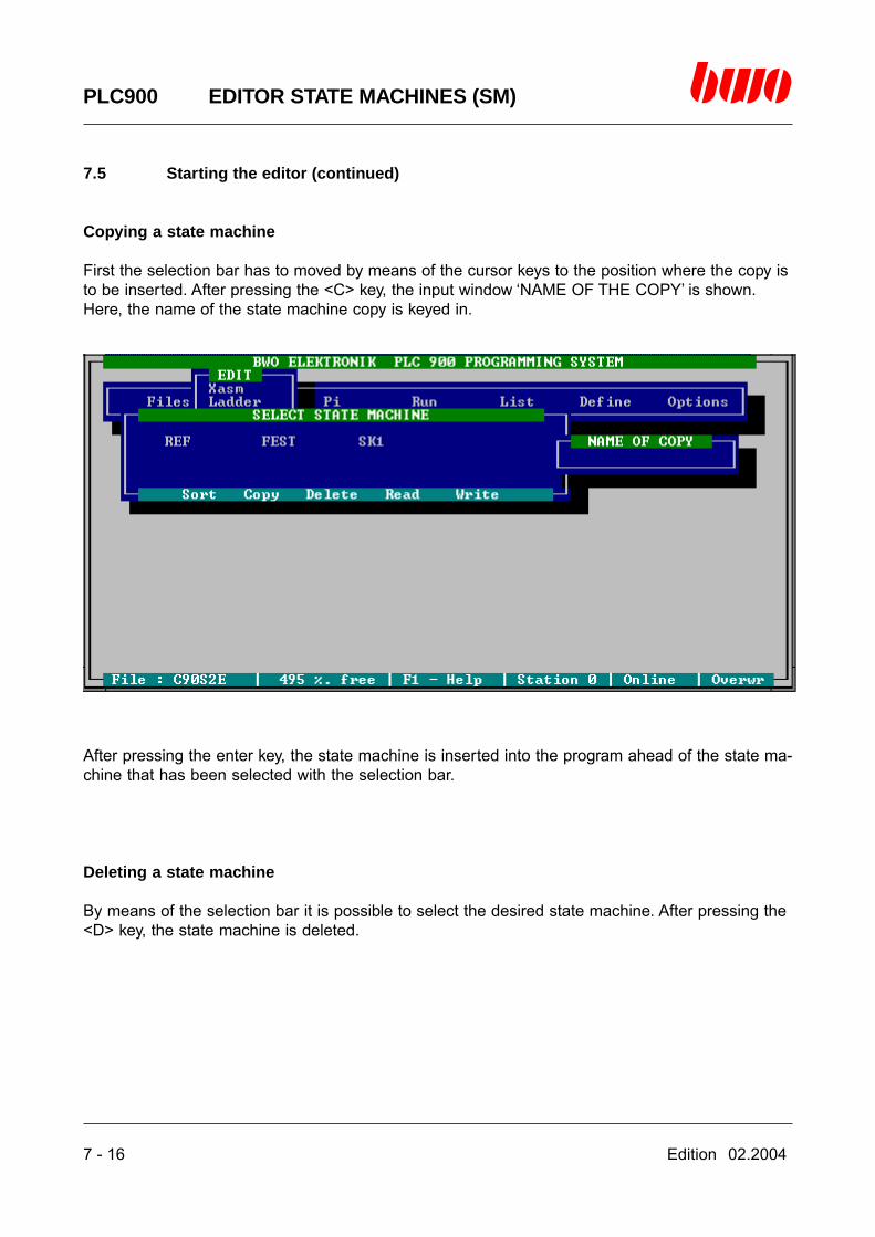
7 - 16 Edition 02.2004
PLC900 EDITOR STATE MACHINES (SM)
7.5 Starting the editor (continued)
Copying a state machine
First the selection bar has to moved by means of the cursor keys to the position where the copy isto be inserted. After pressing the <C> key, the input window ‘NAME OF THE COPY’ is shown.Here, the name of the state machine copy is keyed in.
After pressing the enter key, the state machine is inserted into the program ahead of the state ma-chine that has been selected with the selection bar.
Deleting a state machine
By means of the selection bar it is possible to select the desired state machine. After pressing the<D> key, the state machine is deleted.
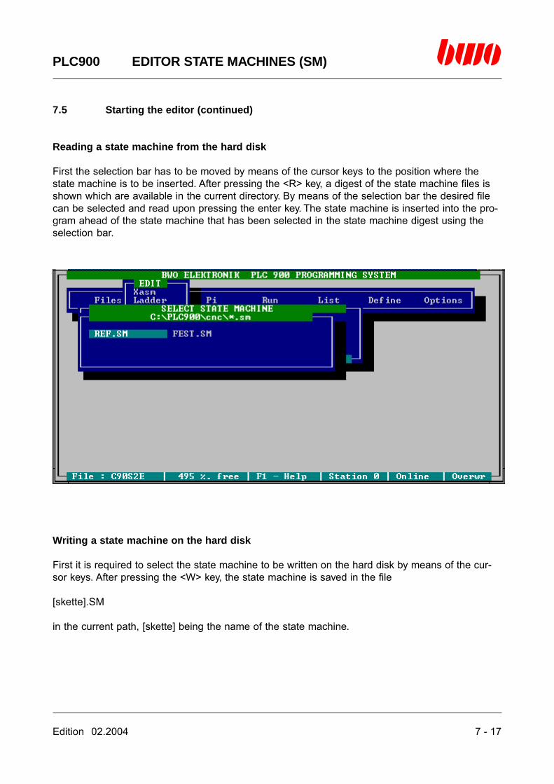
Edition 02.2004 7 - 17
PLC900 EDITOR STATE MACHINES (SM)
7.5 Starting the editor (continued)
Reading a state machine from the hard disk
First the selection bar has to be moved by means of the cursor keys to the position where thestate machine is to be inserted. After pressing the <R> key, a digest of the state machine files isshown which are available in the current directory. By means of the selection bar the desired filecan be selected and read upon pressing the enter key. The state machine is inserted into the pro-gram ahead of the state machine that has been selected in the state machine digest using theselection bar.
Writing a state machine on the hard disk
First it is required to select the state machine to be written on the hard disk by means of the cur-sor keys. After pressing the <W> key, the state machine is saved in the file
[skette].SM
in the current path, [skette] being the name of the state machine.

7 - 18 Edition 02.2004
PLC900 EDITOR STATE MACHINES (SM)
7.5 Starting the editor (continued)
Editor window
After selecting a state machine and pressing the enter key, the editor window is shown. The win-dow heading indicates the name of the current state machine.
Screen format 125 * 150 characters
In the first line of the editor window there are indicated:
- the first 48 characters of the comment of the step resp. of the transition that is below thecursor
- the length of the state machine in the instruction list- the current cursor position
In the second line, the state machine comment is indicated.
A newly created state machine consists of one step and one transition and can be extended bymeans of the editor.If the searching function is activated upon starting the editor, the cursor is moved to the step or tothe transition in which the symbol name resp. the symbolic address searched for is used. Bypressing the <CTRL L> keys it is possible to continue searching in the state machine. If the mag-nifier function is called, the search can be continued with the <CTRL L> keys.For the purpose of editing, the cursor has to be moved to one of the valid cursor positions and thespace bar has to be pressed. Editing is then performed by means of a menu prompting. You willfind the valid cursor positions in the chapter 7.8.

Edition 02.2004 7 - 19
PLC900 EDITOR STATE MACHINES (SM)
7.6 Editor functions
Inserting steps and transitions
Inserting steps and transitions serially:
- If the cursor is positioned on a step, a step and a subsequent transition are inserted above thecursor position.
- If the cursor is positioned on a transition, a transition and a subsequent step are inserted abovethe cursor position.

7 - 20 Edition 02.2004
PLC900 EDITOR STATE MACHINES (SM)
7.6 Editor functions (continued)
- If the cursor is positioned on the end of the structure, a step and a subsequent transition areinserted at the end of the structure.
- Inserting operations are always related to a branch of the state machine, i.e. it is not possible toinsert across a branch line.
- If inserting is not possible according to these rules, the desired operation is performed and thestate machine is logically supplemented with a transition resp. a step.
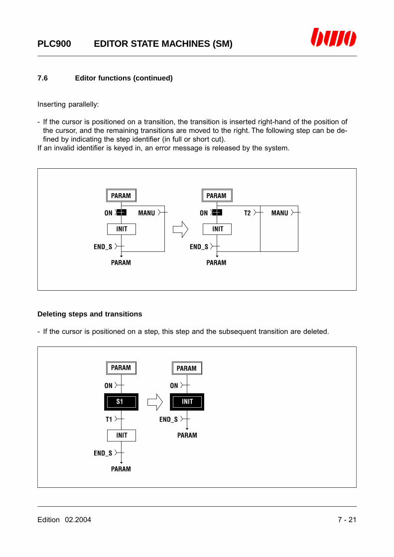
Edition 02.2004 7 - 21
PLC900 EDITOR STATE MACHINES (SM)
7.6 Editor functions (continued)
Inserting parallelly:
- If the cursor is positioned on a transition, the transition is inserted right-hand of the position ofthe cursor, and the remaining transitions are moved to the right. The following step can be de-fined by indicating the step identifier (in full or short cut).
If an invalid identifier is keyed in, an error message is released by the system.
Deleting steps and transitions
- If the cursor is positioned on a step, this step and the subsequent transition are deleted.
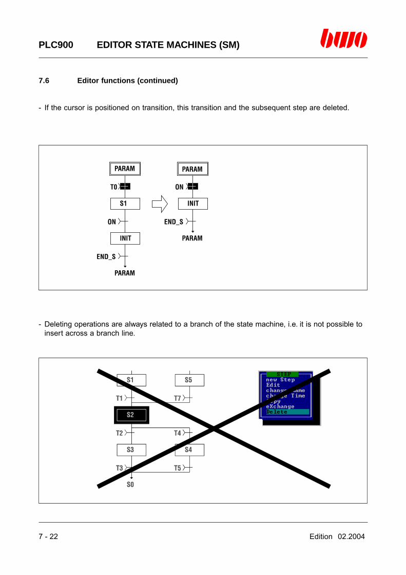
7 - 22 Edition 02.2004
PLC900 EDITOR STATE MACHINES (SM)
7.6 Editor functions (continued)
- If the cursor is positioned on transition, this transition and the subsequent step are deleted.
- Deleting operations are always related to a branch of the state machine, i.e. it is not possible toinsert across a branch line.

Edition 02.2004 7 - 23
PLC900 EDITOR STATE MACHINES (SM)
7.6 Editor functions (continued)
- Upon deleting a transition the whole of the branch is deleted if only this transition is still availablein the concerned branch.
- If deleting is not possible according to these rules, the desired operation is performed and thestate machine is logically corrected by deleting a transition resp. a step.
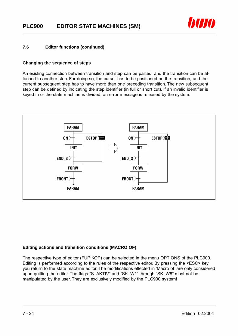
7 - 24 Edition 02.2004
PLC900 EDITOR STATE MACHINES (SM)
7.6 Editor functions (continued)
Changing the sequence of steps
An existing connection between transition and step can be parted, and the transition can be at-tached to another step. For doing so, the cursor has to be positioned on the transition, and thecurrent subsequent step has to have more than one preceding transition. The new subsequentstep can be defined by indicating the step identifier (in full or short cut). If an invalid identifier iskeyed in or the state machine is divided, an error message is released by the system.
Editing actions and transition conditions (MACRO OF)
The respective type of editor (FUP;KOP) can be selected in the menu OPTIONS of the PLC900.Editing is performed according to the rules of the respective editor. By pressing the <ESC> keyyou return to the state machine editor. The modifications effected in ‘Macro of’ are only consideredupon quitting the editor. The flags ”S_AKTIV” and ”SK_W1” through ”SK_W8” must not bemanipulated by the user. They are exclusively modified by the PLC900 system!
Edition 02.2004 7 - 25
PLC900 EDITOR STATE MACHINES (SM)
7.6 Editor functions (continued)
Editing the period of supervision Ts
If the cursor is positioned on a step, the period of time within which one of the subsequent transi-tions has to be complied with can be edited. The actual value of time results from Ts * 10 ms .Ts being the value to be programmed by the user.If Ts > 0 is given, a number can be keyed in that indicates a certain message of the system incase of an error. If Ts = 0 is given, the error number is likewise set to zero.
Copying or exchanging actions / transitions
After selecting the menu item ‘Copy’ resp. ‘Exchange’, the target step resp. target transition can bedefined by indicating the identifier (in full or short cut). If an invalid identifier is keyed in, an errormessage is released by the system. Kindly take in mind that exchanging or copying is reasonableonly between step and step resp. transition and transition since the structure of the state machineis destroyed otherwise!
Editing the organizational step (MACRO OF)
The respective type of editor (FUP;KOP) can be selected in the menu OPTIONS of the PLC900.Editing is performed according to the rules of the respective editor. By pressing the <ESC> keyyou return to the state machine editor. The modifications effected in ‘Macro of’ are only consideredupon quitting the editor. Parameterizing the organizational block is compulsory for the function ofthe state machine editor.
Special functions
Searching functions for EA and flag addressesIf upon starting the editor in the window ‘Network’ a question mark followed by an EA or flag ad-dress (e.g. ‘?M2.1’) is keyed in instead of a state machine name, all of the state machines are dis-played in which the indicated address is present. If one of these state machines is selected there-upon, the cursor goes automatically to the position where the address searched for is to be found.By pressing <∧ L> the cursor is moved to the next position. The searching function is preserved inthe macro-of mode, too, and allows to continue searching for the desired address.

7 - 26 Edition 02.2004
PLC900 EDITOR STATE MACHINES (SM)
7.7 The menu tree of the state machine editor
BWO ELEKTRONIK PLC 900 STATE MACHINES EDITOR - DIAGRAM OF <MENUES>
Overwr File: On line
Lth=47 Line=5 Col=12
INITIAL
INITIAL
FREE
STEP
TRANS
change namechange timeeditnew stepdeletecopyexchange
new step
change nameeditnew transitiondeletecopyexchange
INITIAL STEP
STEP
END OF STRUCT
TRANSITION
change namechange timeeditFubnew stepcopyexchange
serialparallel
TRANSITION
Edit name of structure
Name of structure
Edition 02.2004 7 - 27
PLC900 EDITOR STATE MACHINES (SM)
7.8 Valid commands
The following commands can be translated into a logical network:
NOP no operation.
LDL madress loads an arbitrary memory address with 0 (L).
LDH madress loads an arbitrary memory address with 1 (H).
LCS (constant) loads the lower 16 bits of the TOS register with one extended character.The stack pointer is automatically increased.
LCHS (constant) loads the upper 16 bits of the TOS register.The stack pointer remains unchanged!
LRS madress loads 4 resp. 2 bytes of the memory of an arbitrary memory address intothe TOS register (32 bits resp. 16 bits see SIZE).The stack pointer is automatically increased.
LSR madress loads the TOS register from an arbitrary memory address on into the mem-ory (4 resp. 2 bytes see SIZE).The stack pointer is automatically decreased.
S sets an outputR resets an outputSN negation of SRN negation of R
L madress loads the first operandU madress logical ANDO madress logical OR= madress stores the result
LN madress negation of LUN madress negation of UON madress negation of O=N madress negation of =
Use of parenthetical expressions:
( , U( , UN( , O( , ON( , N( , )
7 - 28 Edition 02.2004
PLC900 EDITOR STATE MACHINES (SM)
7.8 Valid commands (continued)
SPB iadress branch at condition at IS=1
SPBN iadress branch at condition at IS=0
BA iadress like CALL
ISRX loads the storage cell the address of which is contained in the X register,with the contents of the IS register (IS = internal status)Subsequently, the stack pointer is automatically increased.
DUP duplicates TOS. TOS = TOS - 1.The stack pointer is automatically increased.
JMP iadress branches to an absolute address
DCD iadress computed branch
SL n madress branch at condition via n instructions
Edition 02.2004 7 - 29
PLC900 EDITOR STATE MACHINES (SM)
7.9 Messages
Code Meaning Annotation
30 Invalid operation Logical error
31 Invalid number of coils Maximum of 8 directly parallel
32 Invalid position Target address not available
Edition 02.2004 8 - 1
PLC900 EDITOR BWONET
8. Editor BWONET
8.1 Editor control commands 8 - 2
8.2 Introduction 8 - 3
8.3 Starting the editor BWONET 8 - 4
8.4 Menu Station 8 - 5
8.5 Zoom windows 8 - 8
⌧

8 - 2 Edition 02.2004
PLC900 EDITOR BWONET
8.1 Editor control commands
Editor control commands in the digest window
Standard Alternatively Function
<ESC> <ALTMODE> Quits the menu or the function<cursor keys> Move the cursor<space bar> Selects the menu<enter key> Selects the menu or the function<page ↑> <CTRL R> Turns one page up<page ↓> <CTRL C> Turns one page down<Insert> <CTRL V> Insertion mode on/off<F1> <CTRL J> Calls on-line help<F2> Starts symbol editor
Editor commands in the zoom window
Standard Alternatively Function
<ESC> <ALTMODE> Quits the menu or the function<cursor keys> Move the cursor<space bar> Selects the menu<enter key> Selects the menu or the function<Insert> <CTRL V> Insertion mode on/off<F1> <CTRL J> Calls on-line help<F2> Starts the symbol editor

Edition 02.2004 8 - 3
PLC900 EDITOR BWONET
8.2 Introduction
The editor BWONET serves for creating configuration files for networking the control devices ofthe BWO System 900. The configuration file is necessary for providing the individual controldevices of the BWONET (hereinafter called ‘stations’) with informations about the hardware andsoftware components that are available for the BWONET. The configuration file specifies whichstation is defined as the superior (host) station, which input, output and special modules arerequired, which flags are available and which programs are running in the respective stations.The editor BWONET allows to enter the required informations graphically, and there is the addi-tional possibility of obtaining a faster survey of the hardware of all stations.The configuration data are saved in the file ‘NET.CFG’ in the directory \PLC900 and at the sametime transferred to the file
[filename].CFG
[filename] corresponding to the name of the PLC900 program file.
The BWONET configuration file has to be the same in all stations of the unit. This is best guaran-teed by copying the file [filename].CFG by means of the DOS instruction COPY.
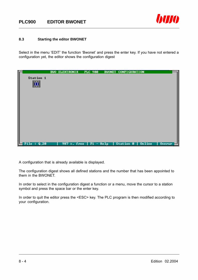
8 - 4 Edition 02.2004
PLC900 EDITOR BWONET
8.3 Starting the editor BWONET
Select in the menu ‘EDIT’ the function ‘Bwonet’ and press the enter key. If you have not entered aconfiguration yet, the editor shows the configuration digest
A configuration that is already available is displayed.
The configuration digest shows all defined stations and the number that has been appointed tothem in the BWONET.
In order to select in the configuration digest a function or a menu, move the cursor to a stationsymbol and press the space bar or the enter key.
In order to quit the editor press the <ESC> key. The PLC program is then modified according toyour configuration.
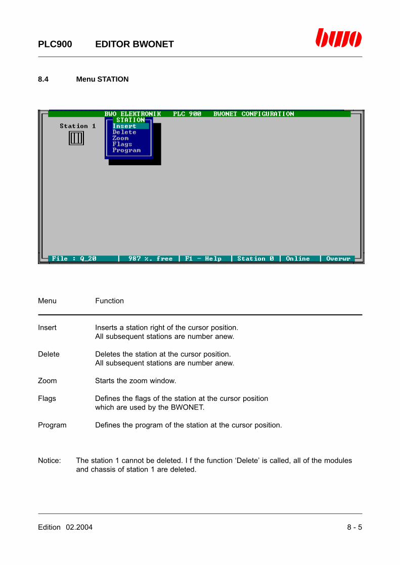
Edition 02.2004 8 - 5
PLC900 EDITOR BWONET
8.4 Menu STATION
Menu Function
Insert Inserts a station right of the cursor position.All subsequent stations are number anew.
Delete Deletes the station at the cursor position.All subsequent stations are number anew.
Zoom Starts the zoom window.
Flags Defines the flags of the station at the cursor positionwhich are used by the BWONET.
Program Defines the program of the station at the cursor position.
Notice: The station 1 cannot be deleted. I f the function ‘Delete’ is called, all of the modulesand chassis of station 1 are deleted.

8 - 6 Edition 02.2004
PLC900 EDITOR BWONET
8.4 Menu STATION (continued)
Flags
After pressing the enter key, the input window ‘FLAGS’ is shown. Here the flags are indicated thatare available in the BWONET.
Each flag symbol defines a block having the size of 32 flags that is provided for the BWONET.The flag symbols have to defined in such a manner that there is no overlapping of the individualblocks. Besides, the first digit in the flag symbol has to coincide with the station number.
Example: Valid flag definitions:
station 3 M3.1.1M3.2.1M3.3.1...
or
station 2 M2.1.10M2.2.10M2.3.10...
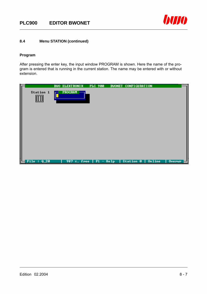
Edition 02.2004 8 - 7
PLC900 EDITOR BWONET
8.4 Menu STATION (continued)
Program
After pressing the enter key, the input window PROGRAM is shown. Here the name of the pro-gram is entered that is running in the current station. The name may be entered with or withoutextension.
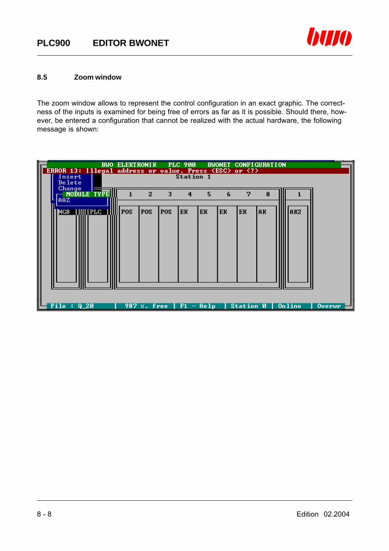
8 - 8 Edition 02.2004
PLC900 EDITOR BWONET
8.5 Zoom window
The zoom window allows to represent the control configuration in an exact graphic. The correct-ness of the inputs is examined for being free of errors as far as it is possible. Should there, how-ever, be entered a configuration that cannot be realized with the actual hardware, the followingmessage is shown:
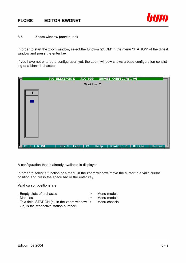
Edition 02.2004 8 - 9
PLC900 EDITOR BWONET
8.5 Zoom window (continued)
In order to start the zoom window, select the function ‘ZOOM’ in the menu ‘STATION’ of the digestwindow and press the enter key.
If you have not entered a configuration yet, the zoom window shows a base configuration consist-ing of a blank 1-chassis:
A configuration that is already available is displayed.
In order to select a function or a menu in the zoom window, move the cursor to a valid cursorposition and press the space bar or the enter key.
Valid cursor positions are
- Empty slots of a chassis -> Menu module- Modules -> Menu module- Text field ‘STATION [n]’ in the zoom window -> Menu chassis
([n] is the respective station number)
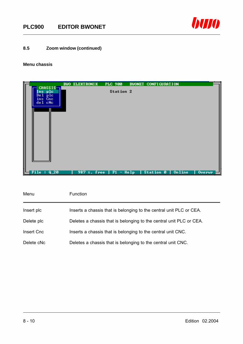
8 - 10 Edition 02.2004
PLC900 EDITOR BWONET
8.5 Zoom window (continued)
Menu chassis
Menu Function
Insert plc Inserts a chassis that is belonging to the central unit PLC or CEA.
Delete plc Deletes a chassis that is belonging to the central unit PLC or CEA.
Insert Cnc Inserts a chassis that is belonging to the central unit CNC.
Delete cNc Deletes a chassis that is belonging to the central unit CNC.
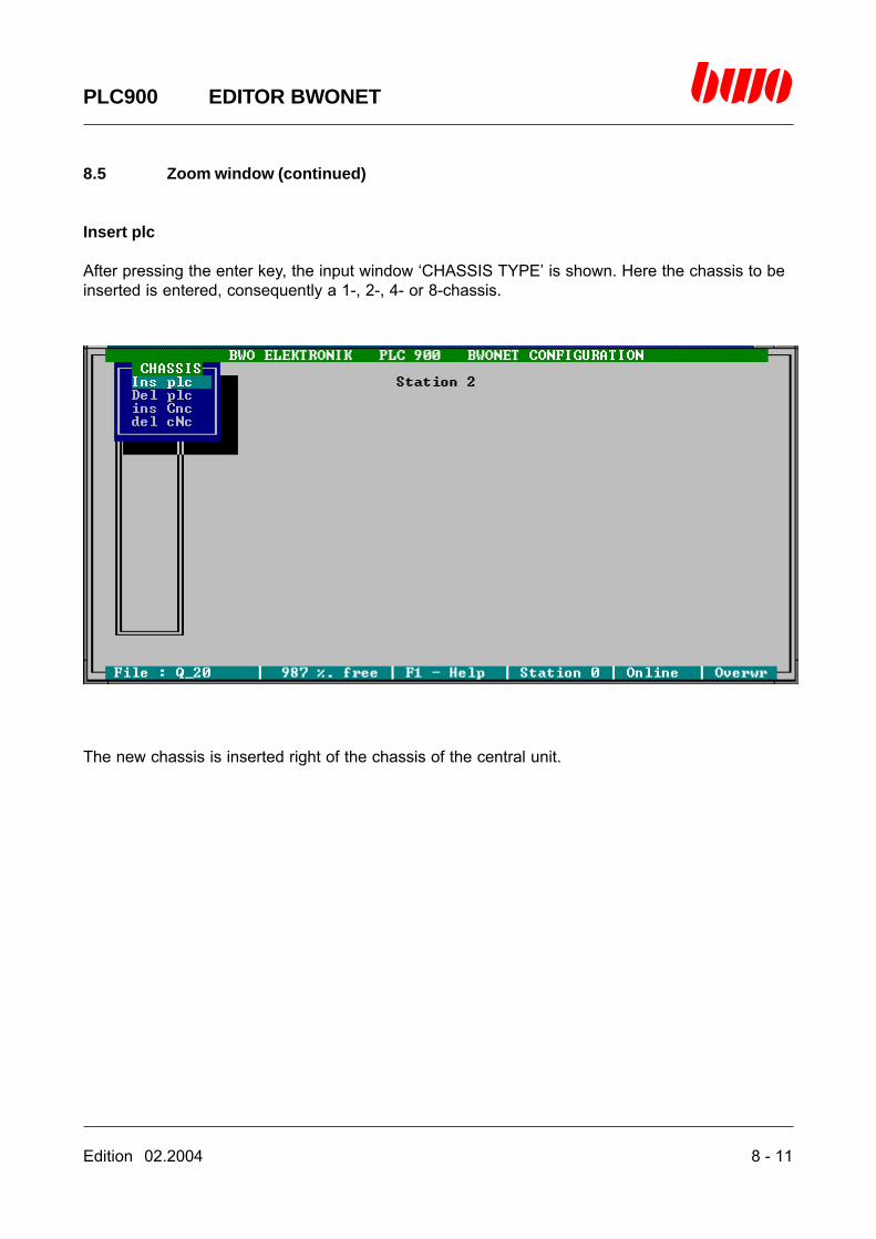
Edition 02.2004 8 - 11
PLC900 EDITOR BWONET
8.5 Zoom window (continued)
Insert plc
After pressing the enter key, the input window ‘CHASSIS TYPE’ is shown. Here the chassis to beinserted is entered, consequently a 1-, 2-, 4- or 8-chassis.
The new chassis is inserted right of the chassis of the central unit.

8 - 12 Edition 02.2004
PLC900 EDITOR BWONET
8.5 Zoom window (continued)
Delete plc
After pressing the enter key, the input window ‘CHASSIS NO’ is shown. Here you enter whichchassis is to be deleted counting it from the central unit.
The chassis can only be deleted on condition that all slots are empty. Otherwise the followingmessage is shown:

Edition 02.2004 8 - 13
PLC900 EDITOR BWONET
8.5 Zoom window (continued)
Insert Cnc
After pressing the enter key, the input window ‘CHASSIS TYPE’ is shown. Here the chassis to beinserted is entered, consequently a 1-, 2-, 4- or 8-chassis.
The new chassis is inserted right of the chassis of the central unit.
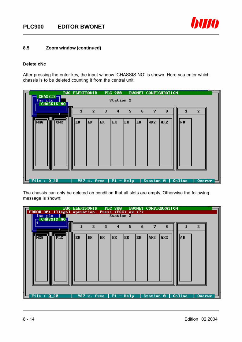
8 - 14 Edition 02.2004
PLC900 EDITOR BWONET
8.5 Zoom window (continued)
Delete cNc
After pressing the enter key, the input window ‘CHASSIS NO’ is shown. Here you enter whichchassis is to be deleted counting it from the central unit.
The chassis can only be deleted on condition that all slots are empty. Otherwise the followingmessage is shown:
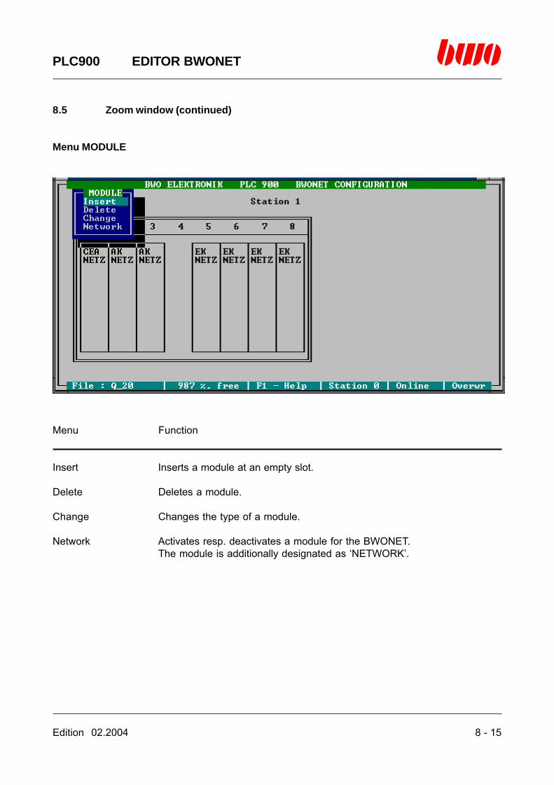
Edition 02.2004 8 - 15
PLC900 EDITOR BWONET
8.5 Zoom window (continued)
Menu MODULE
Menu Function
Insert Inserts a module at an empty slot.
Delete Deletes a module.
Change Changes the type of a module.
Network Activates resp. deactivates a module for the BWONET.The module is additionally designated as ‘NETWORK’.
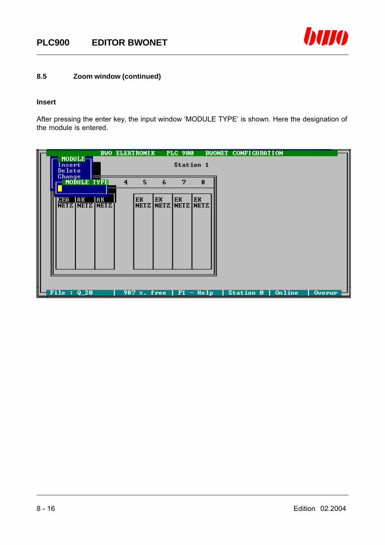
8 - 16 Edition 02.2004
PLC900 EDITOR BWONET
8.5 Zoom window (continued)
Insert
After pressing the enter key, the input window ‘MODULE TYPE’ is shown. Here the designation ofthe module is entered.

Edition 02.2004 8 - 17
PLC900 EDITOR BWONET
8.5 Zoom window (continued)
Designations of the modules:
NG8 Mains supply circuit 8 ANG16 Mains supply circuit 16 ACNC Central unit CNCPLC Central unit PLCCEA Central unit, 16 inlets, 16 outlets, power supply 4 ADSI8 Axes module, 8 axes, digital, activeDSI4 Axes module, 4 axes, digital, passiveAAZ1 Axes module, 2 counters, 1 analog outletAAZ2 Axes module, 2 counters, 2 analog outletsAAZ4 Axes module, 4 axes, analog, passivePOS POS module, 3 axes, analog, incrementalPOA POS module, 3 axes, analog, SSIPOD POS module, 3 axes, 1 spindle, digitalSMM Stepping motor module, 3-foldAEK Inlet/outlet module, 16 inlets, 16 outlets (0.5 A)EK Inlet module, 32 inletsAK Outlet module, 32 outlets (0.5 A)AK2 Outlet module, 16 outlets (2 A)AKR Relay module, 16 outletsDAW2 Digital-analog converter, 2-foldDAW4 Digital-analog converter, 4-foldADW4 Analog-digital converter, 4-foldCOM Communication module
Notice:
A module can be inserted only in an empty slot.The modules NG8, NG16, PLC and CNC are inserted together with the required chassis at theposition where they have to be located according to the description of the hardware.
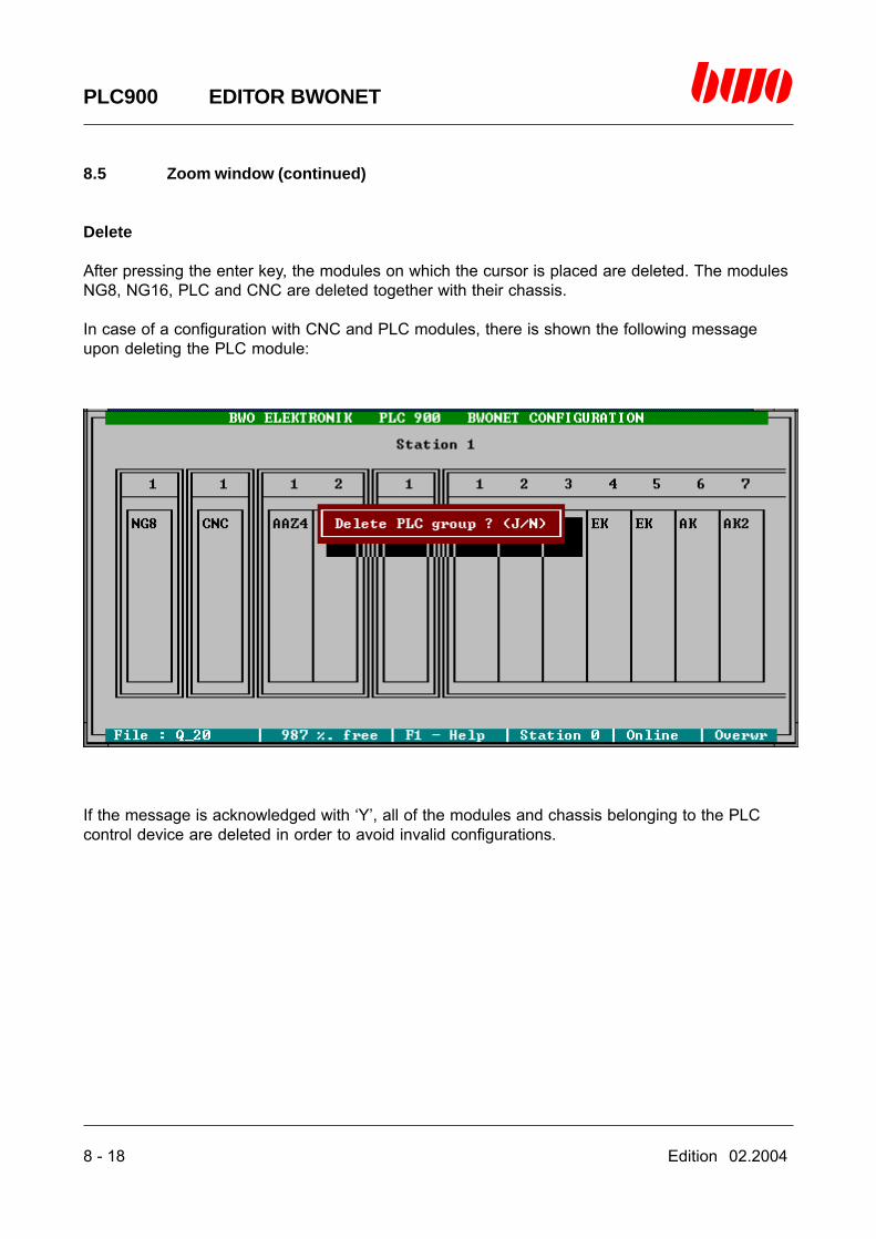
8 - 18 Edition 02.2004
PLC900 EDITOR BWONET
8.5 Zoom window (continued)
Delete
After pressing the enter key, the modules on which the cursor is placed are deleted. The modulesNG8, NG16, PLC and CNC are deleted together with their chassis.
In case of a configuration with CNC and PLC modules, there is shown the following messageupon deleting the PLC module:
If the message is acknowledged with ‘Y’, all of the modules and chassis belonging to the PLCcontrol device are deleted in order to avoid invalid configurations.
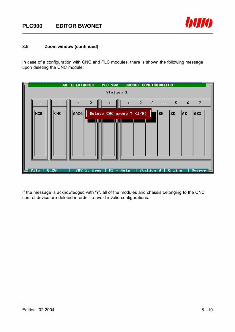
Edition 02.2004 8 - 19
PLC900 EDITOR BWONET
8.5 Zoom window (continued)
In case of a configuration with CNC and PLC modules, there is shown the following messageupon deleting the CNC module:
If the message is acknowledged with ‘Y’, all of the modules and chassis belonging to the CNCcontrol device are deleted in order to avoid invalid configurations.

8 - 20 Edition 02.2004
PLC900 EDITOR BWONET
8.5 Zoom window (continued)
Change
After pressing the enter key, the input window ‘MODULE TYPE’ is shown. Here the new moduledesignation is entered.
Quitting the zoom window
The zoom window can be quitted by pressing the <ESC> key. The inputs are taken over then.

Edition 02.2004 9 - 1
PLC900 MENU PI
9. Menu PI
9.1 Display 9 - 3
9.2 Modify 9 - 5
9.3 Register 9 - 7
9.4 Show 9 - 9
9.5 Logic status recorder (Lsr) 9 -16
9.6 Load 9 -23
9.7 Save 9 -25
⌧
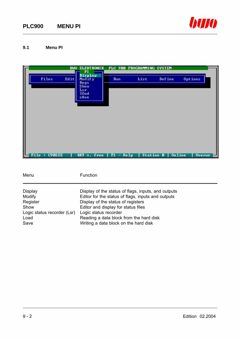
9 - 2 Edition 02.2004
PLC900 MENU PI
9.1 Menu PI
Menu Function
Display Display of the status of flags, inputs, and outputsModify Editor for the status of flags, inputs and outputsRegister Display of the status of registersShow Editor and display for status filesLogic status recorder (Lsr) Logic status recorderLoad Reading a data block from the hard diskSave Writing a data block on the hard disk
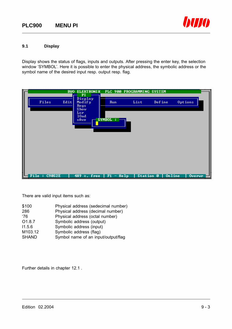
Edition 02.2004 9 - 3
PLC900 MENU PI
9.1 Display
Display shows the status of flags, inputs and outputs. After pressing the enter key, the selectionwindow ‘SYMBOL’. Here it is possible to enter the physical address, the symbolic address or thesymbol name of the desired input resp. output resp. flag.
There are valid input items such as:
$100 Physical address (sedecimal number)286 Physical address (decimal number)‘76 Physical address (octal number)O1.8.7 Symbolic address (output)I1.5.6 Symbolic address (input)M103.12 Symbolic address (flag)SHAND Symbol name of an input/output/flag
Further details in chapter 12.1 .
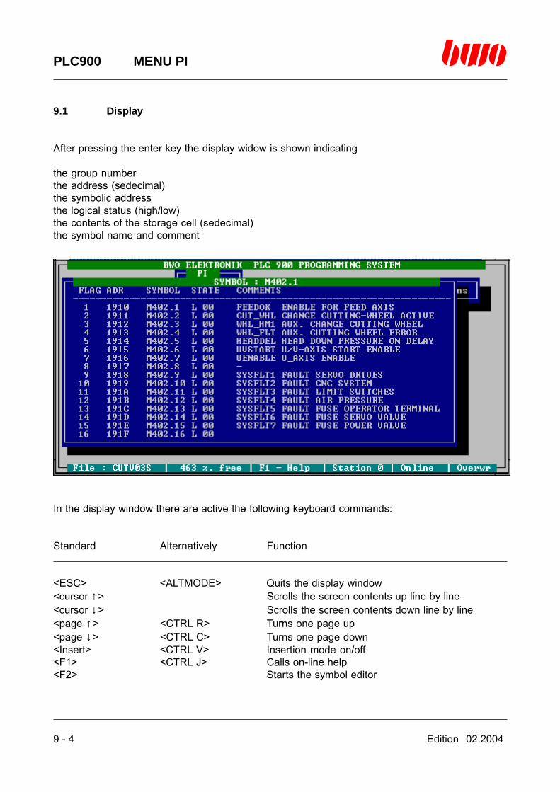
9 - 4 Edition 02.2004
PLC900 MENU PI
9.1 Display
After pressing the enter key the display widow is shown indicating
the group numberthe address (sedecimal)the symbolic addressthe logical status (high/low)the contents of the storage cell (sedecimal)the symbol name and comment
In the display window there are active the following keyboard commands:
Standard Alternatively Function
<ESC> <ALTMODE> Quits the display window<cursor ↑> Scrolls the screen contents up line by line<cursor ↓> Scrolls the screen contents down line by line<page ↑> <CTRL R> Turns one page up<page ↓> <CTRL C> Turns one page down<Insert> <CTRL V> Insertion mode on/off<F1> <CTRL J> Calls on-line help<F2> Starts the symbol editor
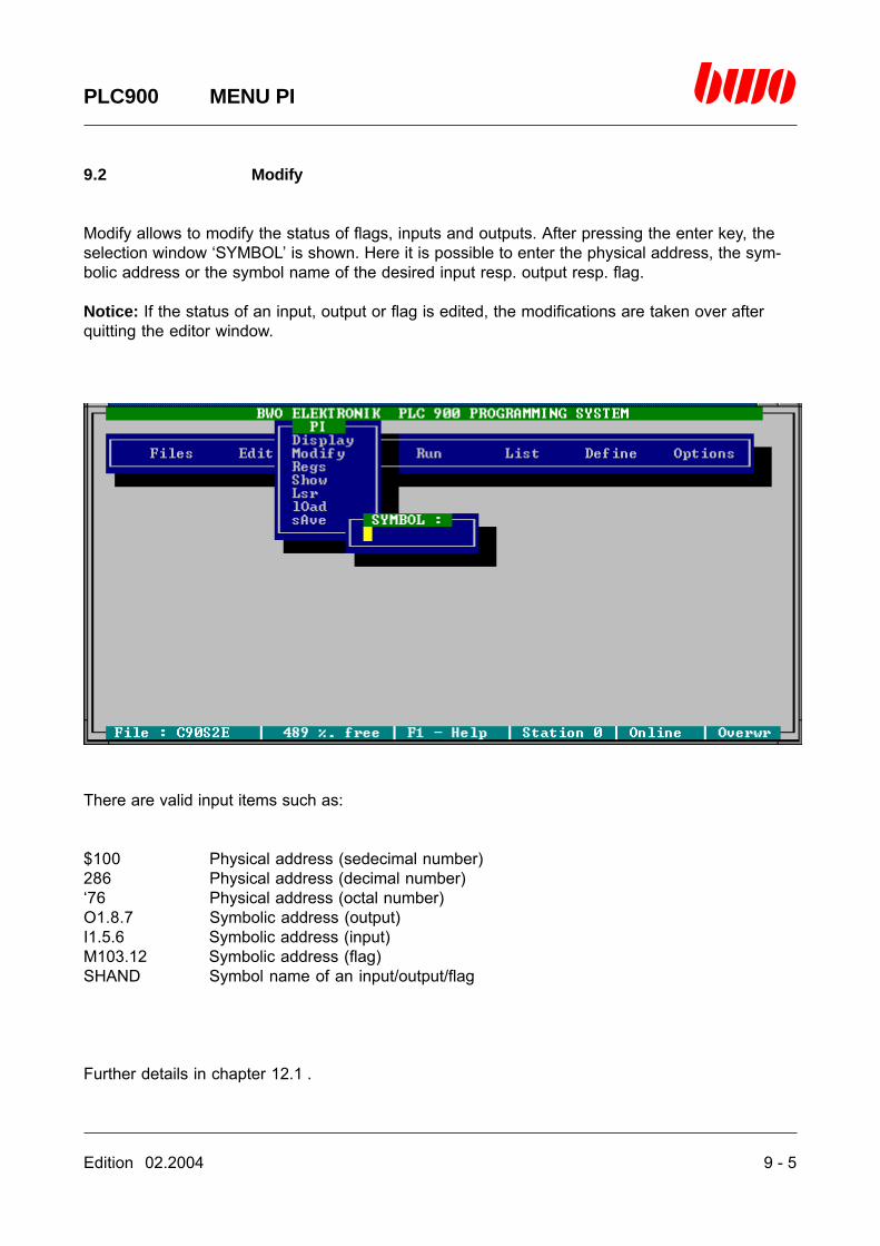
Edition 02.2004 9 - 5
PLC900 MENU PI
9.2 Modify
Modify allows to modify the status of flags, inputs and outputs. After pressing the enter key, theselection window ‘SYMBOL’ is shown. Here it is possible to enter the physical address, the sym-bolic address or the symbol name of the desired input resp. output resp. flag.
Notice: If the status of an input, output or flag is edited, the modifications are taken over afterquitting the editor window.
There are valid input items such as:
$100 Physical address (sedecimal number)286 Physical address (decimal number)‘76 Physical address (octal number)O1.8.7 Symbolic address (output)I1.5.6 Symbolic address (input)M103.12 Symbolic address (flag)SHAND Symbol name of an input/output/flag
Further details in chapter 12.1 .

9 - 6 Edition 02.2004
PLC900 MENU PI
9.2 Modify (continue)
After pressing the enter key the display widow is shown indicating
the group numberthe address (sedecimal)the symbolic addressthe logical status (high/low)the contents of the storage cell (sedecimal)the symbol name and comment
In the display window there are active the following keyboard commands:
Standard Alternatively Function
<ESC> <ALTMODE> Quits the editor window and takes over the modifications<cursor keys> Move the cursor<page ↑> <CTRL R> Turns one page up<page ↓> <CTRL C> Turns one page down<backspace key> <DEL> Blanks the character left of the cursor<DEL> <CTRL G> Blanks the character below the cursor<CTRL Y> Blanks the complete line<CTRL QY> Blanks the line from the cursor till the end of line<Insert> <CTRL V> Insertion mode on/off<F1> <CTRL J> Calls on-line help<F2> Starts the symbol editor

Edition 02.2004 9 - 7
PLC900 MENU PI
9.3 Register
Register displays the memory of the central unit divided into a register of 32 bits (4 flags of 8 bitseach). After pressing the enter key, the selection window ‘REGISTER’ is shown. Here it is possi-ble to enter the physical address, the symbolic address or the symbol name of the flag whichrepresents the beginning of the first register.
There are valid input items such as:
$100 Physical address (sedecimal number)286 Physical address (decimal number)‘76 Physical address (octal number)M103.12 Symbolic address (flag)SHAND Symbol name of a flag
Further details in chapter 12.1 .

9 - 8 Edition 02.2004
PLC900 MENU PI
9.3 Register (continue)
After pressing the enter key the display widow is shown indicating
the register numberthe address (sedecimal)the symbolic addressthe contents of the register (sedecimal)the symbol name and comment
In the display window there are active the following keyboard commands:
Standard Alternatively Function
<ESC> <ALTMODE> Quits the display window<cursor ↑> Scrolls the screen contents up line by line<cursor ↓> Scrolls the screen contents down line by line<page ↑> <CTRL R> Turns one page up<page ↓> <CTRL C> Turns one page down<Insert> <CTRL V> Insertion mode on/off<F1> <CTRL J> Calls on-line help<F2> Starts the symbol editor
Edition 02.2004 9 - 9
PLC900 MENU PI
9.4 Show
By means of Show it is possible to create freely programmable status files. Thus the status offlags, inputs and static outputs can be displayed.A status file consists of a non-varying and a variable contents.The non-varying file contents (frame of file) and text is to be edited by means of the editorcommands.The variable file contents is entered as follows:Bring the cursor into the desired position.Press the <*> key.Subsequently, a menu is shown by means of which the structure of the display field can be deter-mined:
Menu display Meaning
NAME Address or symbolic nameOFFSET Relocation factor to the symbolic address
TYPE Type of the display partBIT Text display fieldBYTE Numerical display fieldWORD Numerical display fieldINTEGER Numerical display fieldLONGINTEGER Numerical display fieldTIME 2 bytesDATE 3 bytesREAL.1 Fixed point numericallyREAL.2 Fixed point numericallyREAL.3 Fixed point numericallyREAL.4 Fixed point numericallyCODE Assembling-back external instructions
STL Displayed text if bit = low (only for type: BIT)STH Displayed text if bit = high (only for type: BIT)
COLORL Colour of the display if bit = low or for numerical fieldsCOLORH Colour of the display if bit = high or cursor colour for input fields
CHANGE FIELD TYPE INPUTOUTPUTBARGRAPH (bar chart)
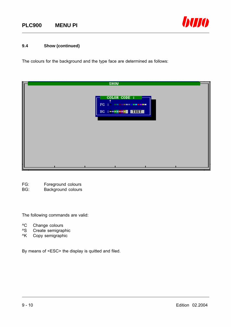
9 - 10 Edition 02.2004
PLC900 MENU PI
9.4 Show (continued)
The colours for the background and the type face are determined as follows:
FG: Foreground coloursBG: Background colours
The following commands are valid:
^C Change colours^S Create semigraphic^K Copy semigraphic
By means of <ESC> the display is quitted and filed.

Edition 02.2004 9 - 11
PLC900 MENU PI
9.4 Show (continued)
Example for entering a status file:Select ‘’Show’ from the main menu and key in the file name.

9 - 12 Edition 02.2004
PLC900 MENU PI
9.4 Show (continued)
Example for entering a status file:After pressing the <*> key, a menu bar is shown. Key in the symbol name.
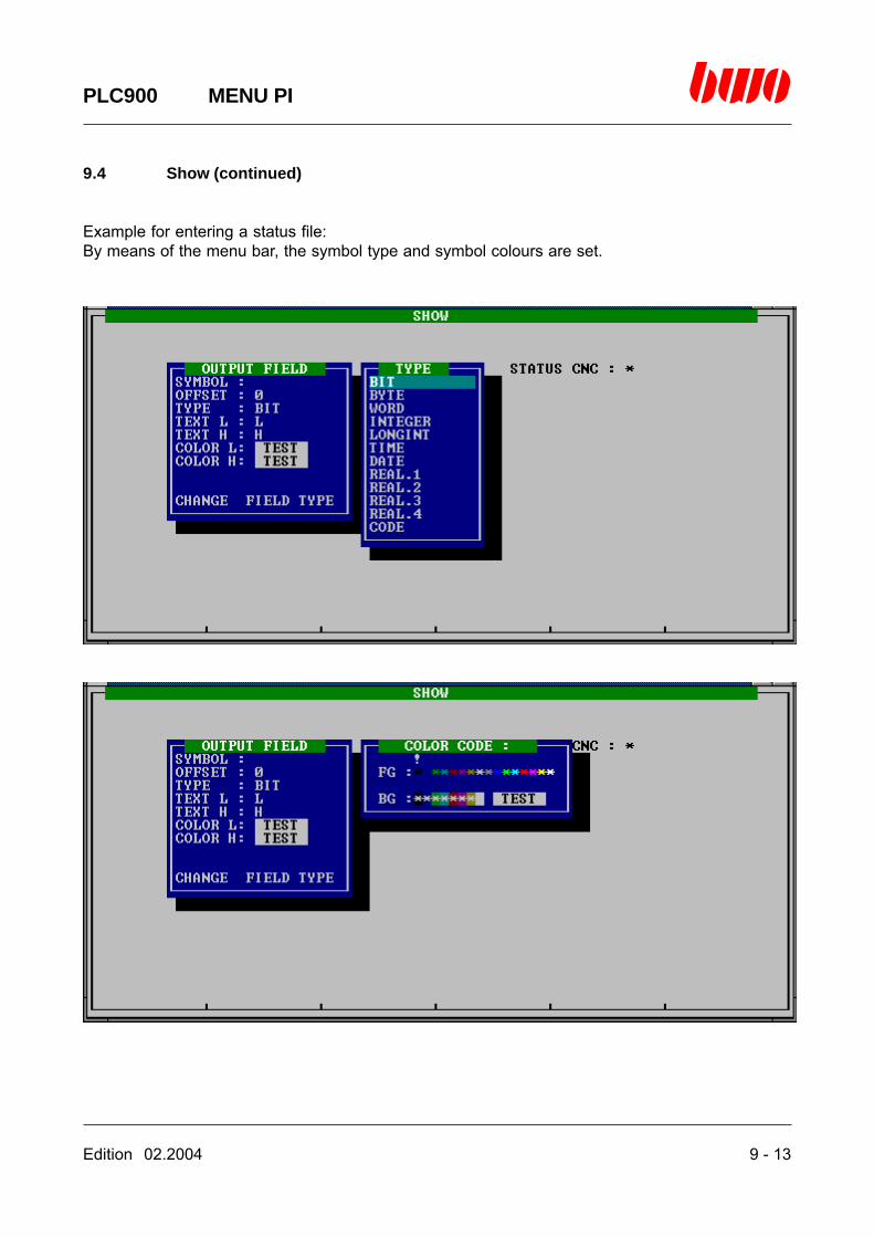
Edition 02.2004 9 - 13
PLC900 MENU PI
9.4 Show (continued)
Example for entering a status file:By means of the menu bar, the symbol type and symbol colours are set.

9 - 14 Edition 02.2004
PLC900 MENU PI
9.4 Show (continued)
Example for entering a status file:By means of the menu bar, the bar diagnosis is set.
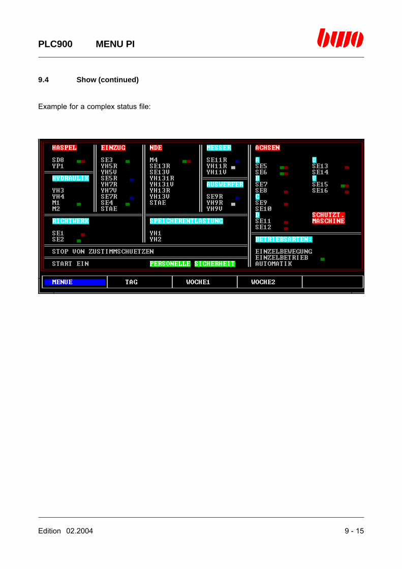
Edition 02.2004 9 - 15
PLC900 MENU PI
9.4 Show (continued)
Example for a complex status file:
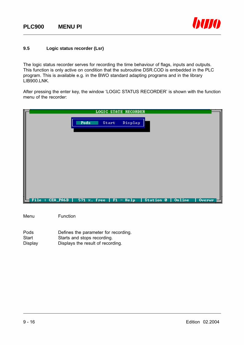
9 - 16 Edition 02.2004
PLC900 MENU PI
9.5 Logic status recorder (Lsr)
The logic status recorder serves for recording the time behaviour of flags, inputs and outputs.This function is only active on condition that the subroutine DSR.COD is embedded in the PLCprogram. This is available e.g. in the BWO standard adapting programs and in the libraryLIB900.LNK.
After pressing the enter key, the window ‘LOGIC STATUS RECORDER’ is shown with the functionmenu of the recorder:
Menu Function
Pods Defines the parameter for recording.Start Starts and stops recording.Display Displays the result of recording.
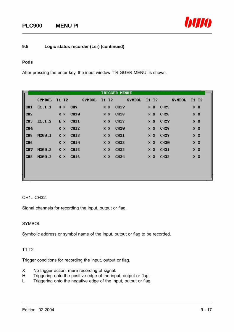
Edition 02.2004 9 - 17
PLC900 MENU PI
9.5 Logic status recorder (Lsr) (continued)
Pods
After pressing the enter key, the input window ‘TRIGGER MENU’ is shown.
CH1...CH32:
Signal channels for recording the input, output or flag.
SYMBOL
Symbolic address or symbol name of the input, output or flag to be recorded.
T1 T2
Trigger conditions for recording the input, output or flag.
X No trigger action, mere recording of signal.H Triggering onto the positive edge of the input, output or flag.L Triggering onto the negative edge of the input, output or flag.
9 - 18 Edition 02.2004
PLC900 MENU PI
9.5 Logic status recorder (Lsr) (continued)
The trigger conditions T1 and T2 are brought into a logical OR-dependence, i.e. on condition thatT1 and T2 are defined, the recording is started if T1 and T2 are complied with.The trigger conditions of the 32 channels are brought into a logical AND-dependence, i.e. oncondition that the trigger conditions of all channels are complied with simultaneously, the record-ing is started.
Move the cursor by means of the cursor keys and define the channels and the trigger conditions.By means of the <ESC> key, you quit the trigger menu and the inputs are taken over.
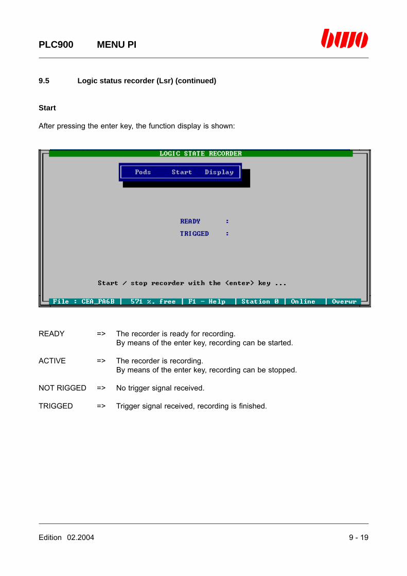
Edition 02.2004 9 - 19
PLC900 MENU PI
9.5 Logic status recorder (Lsr) (continued)
Start
After pressing the enter key, the function display is shown:
READY => The recorder is ready for recording.By means of the enter key, recording can be started.
ACTIVE => The recorder is recording.By means of the enter key, recording can be stopped.
NOT RIGGED => No trigger signal received.
TRIGGED => Trigger signal received, recording is finished.

9 - 20 Edition 02.2004
PLC900 MENU PI
9.5 Logic status recorder (Lsr) (continued)
If the displays ‘READY’ and ‘TRIGGED’ are shown simultaneously, first the trigger signal has tobe taken off and then the recorder has to be stopped by pressing the enter key.If the displays ‘READY’ and ‘NOT TRIGGED’ are shown simultaneously, recording may be startedby pressing the enter key:
The recorder waits for the defined trigger signal. If the trigger signal has been recognized, thefollowing display is shown:

Edition 02.2004 9 - 21
PLC900 MENU PI
9.5 Logic status recorder (Lsr) (continued)
Recording is running. After a short time, the following display is shown:
Recording has been performed successfully. By pressing the <ESC> key, you get back to thefunction menu.

9 - 22 Edition 02.2004
PLC900 MENU PI
9.5 Logic status recorder (Lsr) (continued)
Display
After pressing the enter key, the display window ‘DISPLAY’ is shown:
It shows a time window in which the behaviour of the defined signals is displayed before and afterthe trigger moment. Time base is one PLC program cycle represented by the punctuated linebetween the channel displays. A point corresponds to one PLC cycle. The trigger moment ismarked through a vertical blue bar. The beginning-routine time and the running-out time are 200PLC cycles each.
By means of the <cursor to the left> and <cursor to the right> keys, it is possible to relocate thewindow along with the time axis. The current position being relative to the trigger moment isindicated at the upper edge of the window using the unit of measure T (1 PLC cycle). By meansof the <cursor up> and <cursor down> keys, further channels can be displayed.
By means of the <ESC> key, you can quit the display window again.

Edition 02.2004 9 - 23
PLC900 MENU PI
9.6 Load
With ‘Load’, the files are loaded as a data block from the hard disk into the flag memory of thecentral unit.A data block consists of 16bit words of any number. The first word contains the number of thefollowing words. In order to mark the beginning of the data block, the memory address on whichthe beginning of the data block is to be placed, has to be provided with a symbol name. Thesymbol name must be identical with the file name of the data block.
Structure of the data block:
Example:Starting with the flag M206.1, 20 words are to be read from the hard disk. The data block file hase.g. the name ‘DBANF’. The flag M206.1 subsequently has to be provided with the symbol name‘DBANF’ by means of the symbol editor.If the data block has been read there is available the value $14 (=20) in the flag M206.1 and thevalue 0 in the flag M206.2. In the following 40 flags (40 flags of 8 bits each <=> 20 words of 16bits each) there are the data of the data block.
word 0
word 1
word 2
word 3
word 4
word n-1
word n
number of words
data
data
data
data
data
data
flag
flag + 2
flag + 4
flag + 6
flag + 8
flag + (n-1)*2
flag + n*2
16 bit
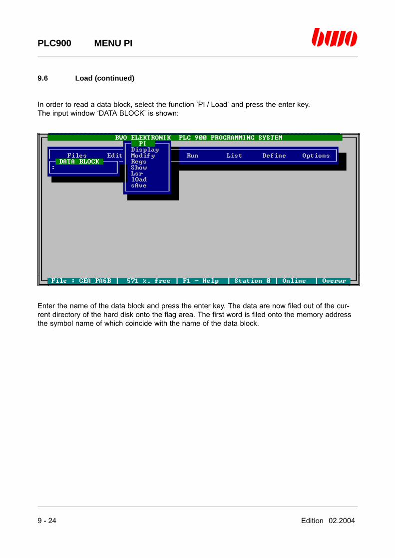
9 - 24 Edition 02.2004
PLC900 MENU PI
9.6 Load (continued)
In order to read a data block, select the function ‘PI / Load’ and press the enter key.The input window ‘DATA BLOCK’ is shown:
Enter the name of the data block and press the enter key. The data are now filed out of the cur-rent directory of the hard disk onto the flag area. The first word is filed onto the memory addressthe symbol name of which coincide with the name of the data block.
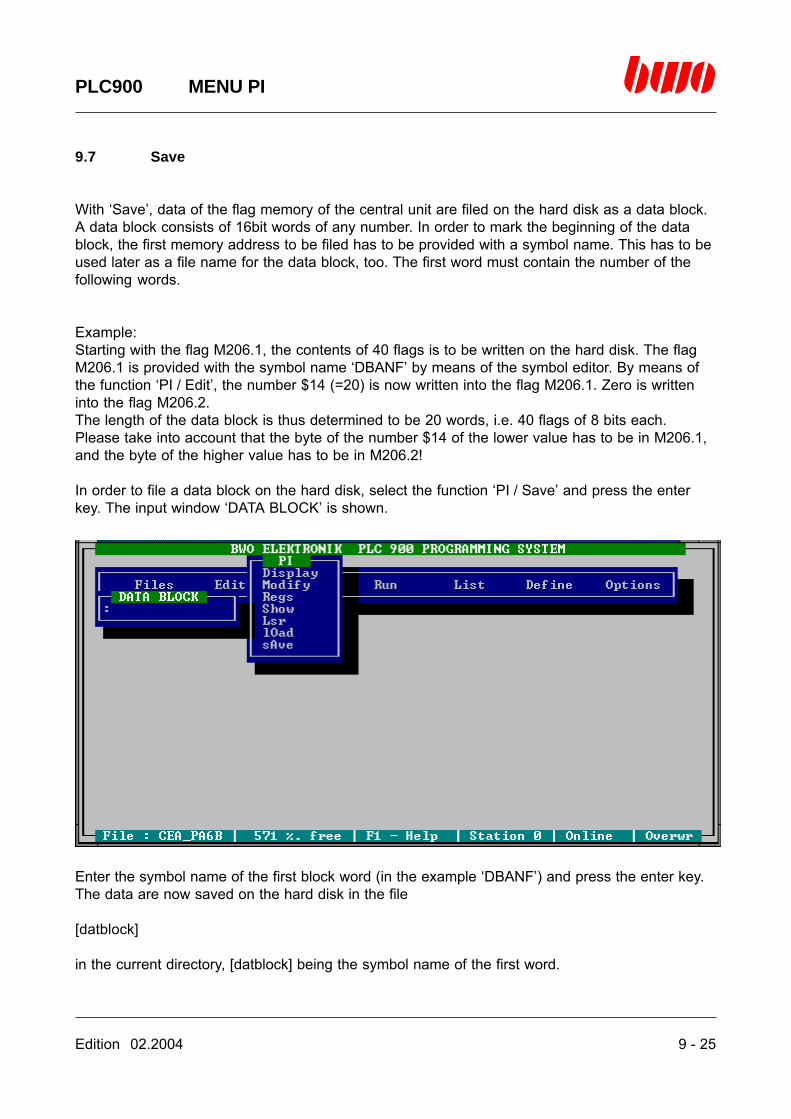
Edition 02.2004 9 - 25
PLC900 MENU PI
9.7 Save
With ‘Save’, data of the flag memory of the central unit are filed on the hard disk as a data block.A data block consists of 16bit words of any number. In order to mark the beginning of the datablock, the first memory address to be filed has to be provided with a symbol name. This has to beused later as a file name for the data block, too. The first word must contain the number of thefollowing words.
Example:Starting with the flag M206.1, the contents of 40 flags is to be written on the hard disk. The flagM206.1 is provided with the symbol name ‘DBANF’ by means of the symbol editor. By means ofthe function ‘PI / Edit’, the number $14 (=20) is now written into the flag M206.1. Zero is writteninto the flag M206.2.The length of the data block is thus determined to be 20 words, i.e. 40 flags of 8 bits each.Please take into account that the byte of the number $14 of the lower value has to be in M206.1,and the byte of the higher value has to be in M206.2!
In order to file a data block on the hard disk, select the function ‘PI / Save’ and press the enterkey. The input window ‘DATA BLOCK’ is shown.
Enter the symbol name of the first block word (in the example ‘DBANF’) and press the enter key.The data are now saved on the hard disk in the file
[datblock]
in the current directory, [datblock] being the symbol name of the first word.
Edition 02.2004 10 - 1
PLC900 RUN
10. Menu Run
10.1 Monitor 10 - 3
10.2 Halt 10 - 5
10.3 Step 10 - 6
10.4 Trace 10 - 9
10.5 Run 10 -11
10.6 Logic 10 -12
10.7 Sm (State machine) 10 -19
⌧
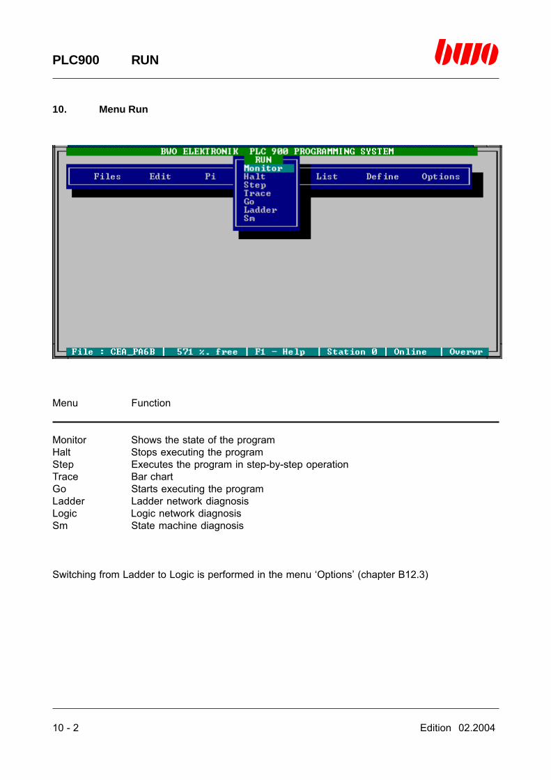
10 - 2 Edition 02.2004
PLC900 RUN
10. Menu Run
Menu Function
Monitor Shows the state of the programHalt Stops executing the programStep Executes the program in step-by-step operationTrace Bar chartGo Starts executing the programLadder Ladder network diagnosisLogic Logic network diagnosisSm State machine diagnosis
Switching from Ladder to Logic is performed in the menu ‘Options’ (chapter B12.3)
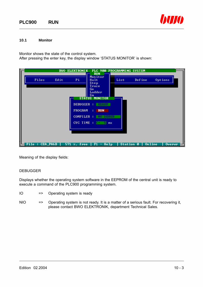
Edition 02.2004 10 - 3
PLC900 RUN
10.1 Monitor
Monitor shows the state of the control system.After pressing the enter key, the display window ‘STATUS MONITOR’ is shown:
Meaning of the display fields:
DEBUGGER
Displays whether the operating system software in the EEPROM of the central unit is ready toexecute a command of the PLC900 programming system.
IO => Operating system is ready
NIO => Operating system is not ready. It is a matter of a serious fault. For recovering it,please contact BWO ELEKTRONIK, department Technical Sales.

10 - 4 Edition 02.2004
PLC900 RUN
10.1 Monitor (continued)
PROGRAM
Shows the current status of the program in the central unit.
RUN => The program is running.STOP => The program was halted by the user or by the PLC900 system in case of
error.
COMPILER
Shows the current status of the PLC instruction compiler in the central unit.
NO ERROR => The program has been able to be translated correctly.
ERROR => In the operating system in the EEPROM of the central unit there hasoccurred an error that is not safeguarded against by the PLC900 program-ming system, e.g. an error of handling breakpoints. It is a matter of aserious fault. For recovering it, please contact BWO ELEKTRONIK, de-partment Technical Sales.
STK OWFLV => During executing the program there has occurred an overflow or underflowof the TOS memory (programming error).
UNDEF LABEL => The program tries to execute a branch instruction to an unknown label(programming error).
CYC TIME
Shows the time that is required for one PLC cycle of the program. The cycle time is divided intosteps of 5 ms each. The shortest cycle time to be displayed is less than or equal to 5 ms. Shouldyour program have a cycle time that is greater than or equal to 200 ms, executing the PLC pro-gram is no longer possible (see part A, installation manual, for that purpose).

Edition 02.2004 10 - 5
PLC900 RUN
10.2 Halt
Halt stops the program execution in the central unit.After pressing the enter key, the display window ‘STATUS MONITOR’:
You find comments for the display window in the section B10.1 .

10 - 6 Edition 02.2004
PLC900 RUN
10.3 Step
Editor control commands in step-by-step operation
Standard Alternatively Function
<ESC> <ALTMODE> Quits the step-by-step display
<Space bar> Executes a program instruction
<CTRL F> Searches for an absolute or symbolic address, asymbol name or a label, and executes the programtill the concerning program line in normal operation
<P> Switches step-by-step execution of subroutines on resp. off
<Insert> <CTRL V> Insertion mode on/off
<F1> <CTRL J> Calls on-line help
<F2> Starts the symbol editor

Edition 02.2004 10 - 7
PLC900 RUN
10.3 Step (continued)
Starting the step-by-step operation
After pressing the enter key, the PLC program is halted at the absolute program address $0000,and the PLC program is displayed in the assembler:
The cursor bar is placed on the program instruction that is executed next. If this instruction beingan operand has a flag or an input, the state of the flag resp. input is displayed left of the programaddress with the letters ‘H’ (for high level) and ‘L’ (for low level). By pressing the space bar, theprogram instruction is executed and the cursor is placed on the next instruction.
By pressing the <P> key it is possible to affect whether the subroutines are likewise run in step-by-step mode (PON) or the subroutine request is executed as one individual program instruction(POFF). Thereby, circumstances permitting, the diagnosis may be accelerated considerably.
10 - 8 Edition 02.2004
PLC900 RUN
10.3 Step (continued)
The window ‘REGISTER’ at the upper edge of the screen shows the following information:
X Contents of the index register XY Contents of the index register Y
SP Contents of the stackpointer (points to the undermost TOS register)IS Contents of the internal status register (contains the result of logical operations)
TOS-1 Contents of the TOS register being subsequent to the undermost TOS registerTOS Contents of the undermost TOS register
PON/POFF Execution of subroutines on/off
Further informations, e.g. on the status of flags, inputs and outputs, can be obtained by quittingthe step-by-step operation (<ESC> key) and requesting the functions ‘PI / Display’ and ‘PI / Regs’.Upon requesting the step-by-step operation anew the program stands on the same programaddress as before.
End step-by-step operation
In order to quit the step-by-step operation, press the <ESC> key. The program stops after theinstruction executed last.
Edition 02.2004 10 - 9
PLC900 RUN
10.4 Trace
Editor control commands in the bar diagnosis
Standard Alternatively Function
<ESC> <ALTMODE> Quits the bar diagnosis
<page ↑> <CTRL R> Turns one page up<page ↓> <CTRL C> Turns one page down
<CTRL QR> Turns pages till the beginning of program<CTRL QC> Turns pages till the end of program
<CTRL F> Searches for an absolute or symbolic address, a symbolname or a label
<CTRL L> Continues searching (see <CTRL F>)
<CTRL O> Displays the branch target of the branch instruction whichis located in the first displayed line of the diagnosiswindow.
<CTRL P> Returns to the branch instruction(reversion of <CTRL O>)
<Insert> <CTRL V> Insertion mode on/off
<F1> <CTRL J> Calls on-line help
<F2> Starts the symbol editor
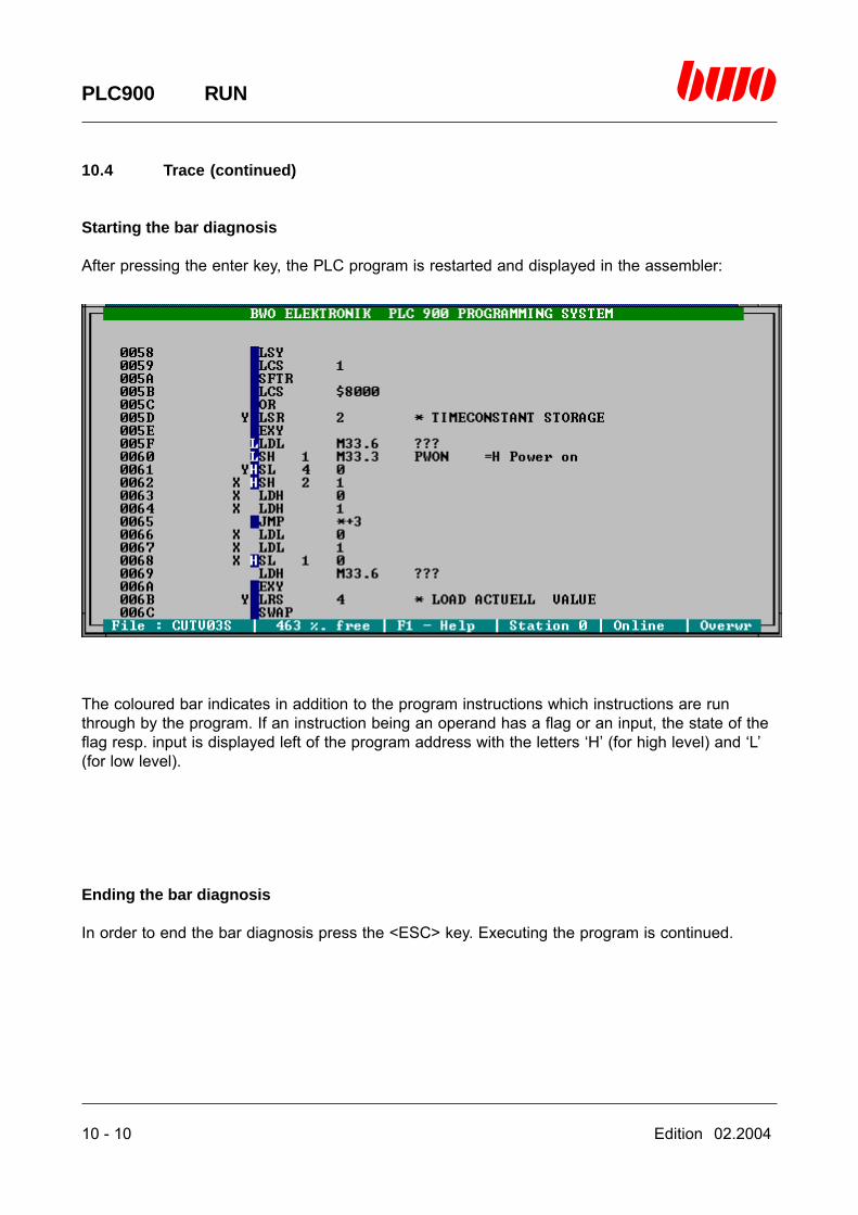
10 - 10 Edition 02.2004
PLC900 RUN
10.4 Trace (continued)
Starting the bar diagnosis
After pressing the enter key, the PLC program is restarted and displayed in the assembler:
The coloured bar indicates in addition to the program instructions which instructions are runthrough by the program. If an instruction being an operand has a flag or an input, the state of theflag resp. input is displayed left of the program address with the letters ‘H’ (for high level) and ‘L’(for low level).
Ending the bar diagnosis
In order to end the bar diagnosis press the <ESC> key. Executing the program is continued.
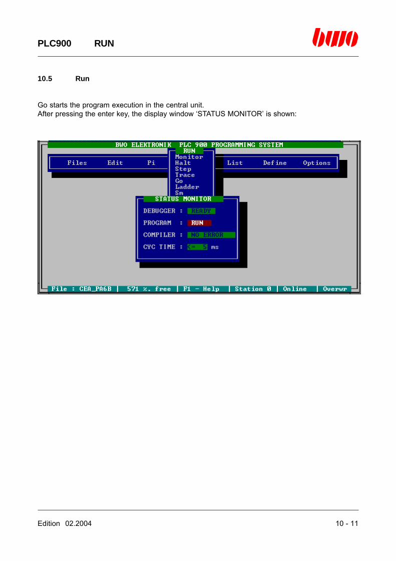
Edition 02.2004 10 - 11
PLC900 RUN
10.5 Run
Go starts the program execution in the central unit.After pressing the enter key, the display window ‘STATUS MONITOR’ is shown:
10 - 12 Edition 02.2004
PLC900 RUN
10.6 Ladder/Logic
Editor control commands
Standard Alternatively Function
<ESC> <ALTMODE> Ends menu or function
<cursor keys> Move the cursor
<space bar> Displays network comments<enter key> Displays network comments
<page ↑> <CTRL R> Turns one page up<page ↓> <CTRL C> Turns one page down
<CTRL QS> Turns one page left<CTRL QD> Turns on page right
<CTRL X> Switches between symbolic address and symbol name<CTRL L> Searches for next address (see search functions)
<Insert> <CTRL V> Insertion mode on/off
<F1> <CTRL J> Calls on-line help
<F2> Starts the symbol editor
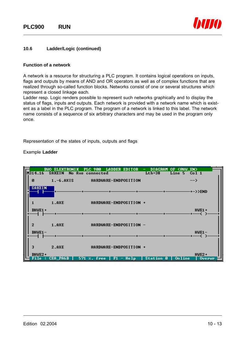
Edition 02.2004 10 - 13
PLC900 RUN
10.6 Ladder/Logic (continued)
Function of a network
A network is a resource for structuring a PLC program. It contains logical operations on inputs,flags and outputs by means of AND and OR operators as well as of complex functions that arerealized through so-called function blocks. Networks consist of one or several structures whichrepresent a closed linkage each.Ladder resp. Logic renders possible to represent such networks graphically and to display thestatus of flags, inputs and outputs. Each network is provided with a network name which is exist-ent as a label in the PLC program. The program of a network is linked to this label. The networkname consists of a sequence of six arbitrary characters and may be used in the program onlyonce.
Representation of the states of inputs, outputs and flags
Example Ladder
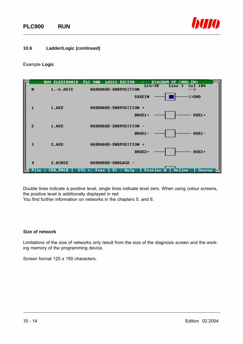
10 - 14 Edition 02.2004
PLC900 RUN
10.6 Ladder/Logic (continued)
Example Logic
Double lines indicate a positive level, single lines indicate level zero. When using colour screens,the positive level is additionally displayed in red.You find further information on networks in the chapters 5. and 6.
Size of network
Limitations of the size of networks only result from the size of the diagnosis screen and the work-ing memory of the programming device.
Screen format 125 x 150 characters.

Edition 02.2004 10 - 15
PLC900 RUN
10.6 Ladder/Logic (continued)
Starting the network diagnosis
After pressing the enter key, the selection window ‘NETWORK’ is shown. Here it is possible toenter the name of the network to be displayed.
If there is not entered any network name, a digest of all networks is shown.
10 - 16 Edition 02.2004
PLC900 RUN
10.6 Ladder/Logic (continued)
If there is entered a question mark followed by a symbol name or by a symbolic address of a flagor of an input or output instead of a network name, only the networks are shown in which thesymbol name resp. the symbolic address is used. Thereby the search function is activated.
If there is entered a star and a question mark followed by a symbol name or by a symbolic ad-dress of a flag or of an input or output instead of a network name, only the networks are shown inwhich the symbol name resp. the symbolic address are influenced. Thereby the search function isactivated.
The networks are listed as a standard in the order in which they are present in the program. Bymeans of the selection bar, the desired network can then be selected and requested with theenter key.
Sorting the network digest
With the <S> key the order of the display can be changed to alphabetical order. Pressing the <S>key once more sorts the network digest again in the order of the program.The selected sort sequence is preserved till the termination of the PLC900 system.
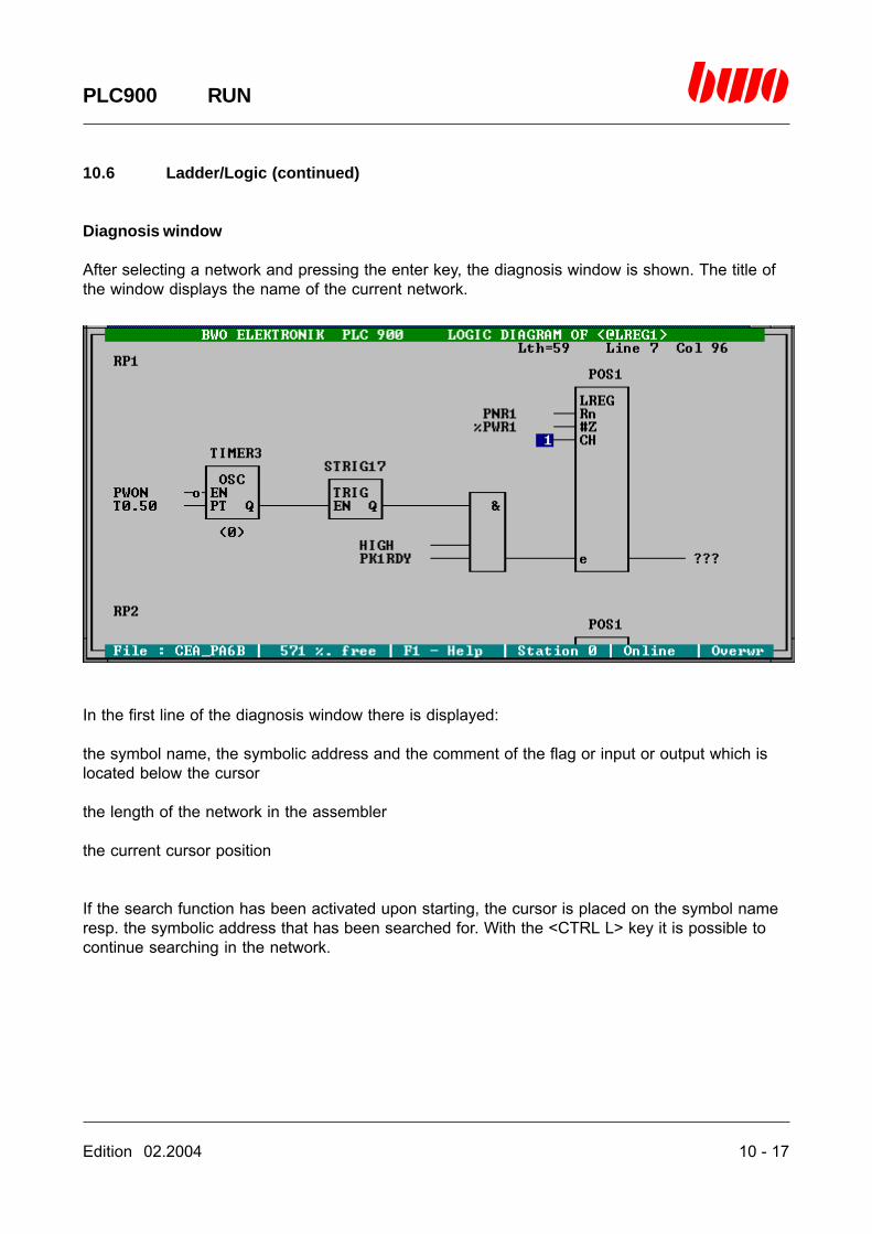
Edition 02.2004 10 - 17
PLC900 RUN
10.6 Ladder/Logic (continued)
Diagnosis window
After selecting a network and pressing the enter key, the diagnosis window is shown. The title ofthe window displays the name of the current network.
In the first line of the diagnosis window there is displayed:
the symbol name, the symbolic address and the comment of the flag or input or output which islocated below the cursor
the length of the network in the assembler
the current cursor position
If the search function has been activated upon starting, the cursor is placed on the symbol nameresp. the symbolic address that has been searched for. With the <CTRL L> key it is possible tocontinue searching in the network.

10 - 18 Edition 02.2004
PLC900 RUN
10.6 Ladder/Logic (continued)
Network comments
To each structure of a network there is belonging a network comment which consists of a maxi-mum of 19 text lines. In the diagnosis window there is shown only the first line of this text in orderto preserve the clearness of the structures. In order to display the network comment, the cursorhas to be moved to the next line above the structure and the enter key or the space bar has to bepressed. The text window ‘STRUCTURE NAME’ is shown:
In order to quit the text window, the <ESC> key has to be pressed.
Quitting the diagnosis window
The diagnosis window is quitted by pressing the <ESC> key.

Edition 02.2004 10 - 19
PLC900 RUN
10.7 Sm (State machine)
Editor control commands in the diagnosis window
Standard Alternatively Function
<ESC> <ALTMODE> Ends menu or function
<cursor keys> Move the cursor
<space bar> Selects menu<enter key> Selects menu or function
<page ↑> <CTRL R> Turns one page up<page ↓> <CTRL C> Turns one page down
<CTRL QS> Turns one page left<CTRL QD> Turns on page right
<CTRL X> Switches between full and short designation<CTRL L> Searches for next address (see search functions)
<Insert> <CTRL V> Insertion mode on/off
<F1> <CTRL J> Calls on-line help
<F2> Starts the symbol editor

10 - 20 Edition 02.2004
PLC900 RUN
10.7 Sm (State machine) (continued)
Function of state machine
A state machine is a resource for structuring a PLC program. It consists of a sequence of stepsand transitions which is passed through from top to bottom. The steps thereby represent programparts, the transitions represent the conditions for changing-over from one program part to an-other. After the run, the program turns back to the start and performs the state machine anew.With Sm it is possible to represent state machines graphically and to display their status. Eachstate machine is provided with a state machine name which is existent as a label into the PLCprogram. To this label there is contiguous the program of a state machine. The state machinename consists of a sequence of six arbitrary characters and may be used in the program onlyonce.
Representation of the status of a state machine
The step on which the state machine is located currently is displayed with a coloured background.When being error-free, the active step has a green background. If the step has a supervisory timeand if this is exceeded, the error is displayed by giving the concerned step a red background. Youfind further informations on state machines in chapter 7.
Starting the state machine diagnosis
After pressing the enter key, the selection window ‘STATE MACHINE’ is shown. Here it is possibleto enter the name of the state machine to be displayed.

Edition 02.2004 10 - 21
PLC900 RUN
10.7 Sm (State machine) (continued)
If there is not entered any state machine, a digest of all state machines is shown.
In the state machine digest there are marked all state machines with a star (‘*’) that are in errorstatus.
If instead of a state machine name a question mark followed by a symbol name or a symbolicaddress of a flag or of an input or output is keyed in, only the state machines are shown in whichthe symbol name resp. the symbolic address is used. Doing so, the search function is activated.
If instead of a state machine name a star and a question mark followed by a symbol name or asymbolic address of a flag or of an output are keyed in, only the state machines are shown inwhich the symbol name resp. the symbolic address is influenced. Doing so, the search function isactivated.
The state machines are listed as a standard in the order in which they are present in the program.By means of the selection bar, the desired state machine can then be selected and requestedwith the enter key.

10 - 22 Edition 02.2004
PLC900 RUN
10.7 Sm (State machine) (continued)
Sorting the state machine digest
With the <S> key the order of the display can be changed to alphabetical order. Pressing the <S>key once more sorts the state machine digest again in the order of the program.The selected sort sequence is preserved till the termination of the PLC900 system.
Diagnosis window
After selecting a state machine and pressing the enter key, the diagnosis window is shown. Thetitle of the window indicates the name of the current state machine.
Screen format 125 x 150 characters
In order to activate the cursor in the diagnosis window press the space bar or the enter key.
In the first line of the diagnosis window there are displayed:the first 48 characters of comment of the step resp. transition that is located below the cursorthe length of the state machine in the assemblerthe current cursor position
In the second line there is displayed the state machine comment.
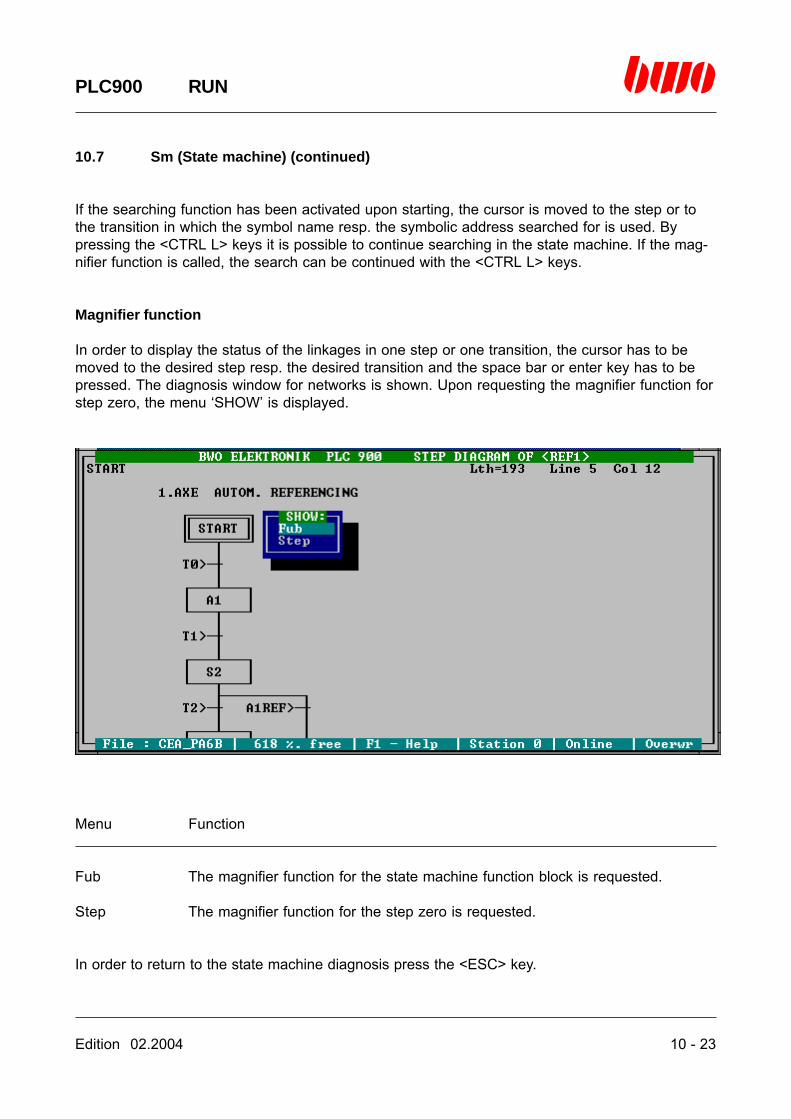
Edition 02.2004 10 - 23
PLC900 RUN
10.7 Sm (State machine) (continued)
If the searching function has been activated upon starting, the cursor is moved to the step or tothe transition in which the symbol name resp. the symbolic address searched for is used. Bypressing the <CTRL L> keys it is possible to continue searching in the state machine. If the mag-nifier function is called, the search can be continued with the <CTRL L> keys.
Magnifier function
In order to display the status of the linkages in one step or one transition, the cursor has to bemoved to the desired step resp. the desired transition and the space bar or enter key has to bepressed. The diagnosis window for networks is shown. Upon requesting the magnifier function forstep zero, the menu ‘SHOW’ is displayed.
Menu Function
Fub The magnifier function for the state machine function block is requested.
Step The magnifier function for the step zero is requested.
In order to return to the state machine diagnosis press the <ESC> key.
10 - 24 Edition 02.2004
PLC900 RUN
10.7 Sm (State machine) (continued)
Quitting the diagnosis window
The diagnosis window is quitted by pressing the <ESC> key.
Edition 02.2004 11 - 1
PLC900 LIST
11. List
11.1 Selection windows 11 - 2
11.2 Layout of the listing 11 -11
11.3 Examples and comments 11 -16
⌧
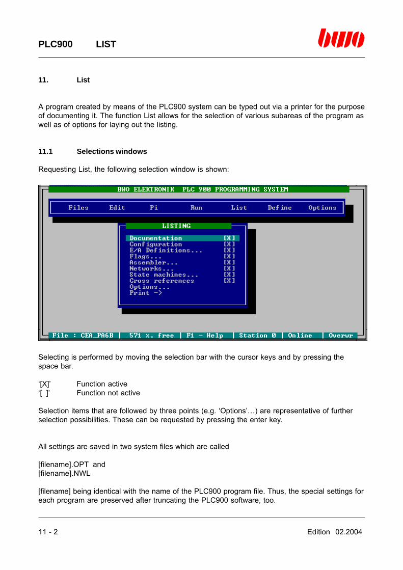
11 - 2 Edition 02.2004
PLC900 LIST
11. List
A program created by means of the PLC900 system can be typed out via a printer for the purposeof documenting it. The function List allows for the selection of various subareas of the program aswell as of options for laying out the listing.
11.1 Selections windows
Requesting List, the following selection window is shown:
Selecting is performed by moving the selection bar with the cursor keys and by pressing thespace bar.
‘[X]’ Function active‘[ ]’ Function not active
Selection items that are followed by three points (e.g. ‘Options’…) are representative of furtherselection possibilities. These can be requested by pressing the enter key.
All settings are saved in two system files which are called
[filename].OPT and[filename].NWL
[filename] being identical with the name of the PLC900 program file. Thus, the special settings foreach program are preserved after truncating the PLC900 software, too.
Edition 02.2004 11 - 3
PLC900 LIST
11.1 Selections windows (continued)
The following functions can be activated by means of the selection window:
Documentation
If the function is active, a documentation text is printed for the program. The text is automaticallytaken by the PLC900 system from a text file which can be created and processed by means ofevery DOS editor. The length of the text may be arbitrary. The name of the text file has to be
[filename].PHD
[filename] being identical with the name of the PLC900 program file. The text file has to be in thedirectory that has been indicated as the printing directory of the PLC900 in the file PLC900.CFG,consequently e.g. ‘C:\PLC900\PRINT’.
Configuration
If the function is active, the configuration of the BWONET is printed out in case of networkedcontrol devices.
I/O definitions…
If the function is active, there is, according to the selection, printed the complete or part of the listof the symbolic input and output definitions.
Flags…
If the function is active, there is, according to the selection, printed out the complete or part of thelist of the symbolic flag definitions.
Assembler…
If the function is active, there is, according to the selection, printed out the complete or part of thePLC900 program in the assembler.
Network…
If the function is active, there are, according to the selection, printed out one or several networks.The kind of layout is determined with the selection item ‘Options’.

11 - 4 Edition 02.2004
PLC900 LIST
11.1 Selections windows (continued)
State machines…
If the function is active, there are, according to the selection, printed out one or several statemachines. The kind of layout is determined with the selection item ‘Options’.
Cross references
If the function is active, the cross references for the assembler, networks and state machines areprinted out as far as these functions are activated.
Options…
By pressing the enter key, the selection window for additional options is requested.
Print ->
By pressing the enter key, the listing is started. First the program is converted into a format thatcan be printed. The current status of this procedure and the number of processed pages aredisplayed:
If the printout is to be performed with a printer, the program is typed out to the printer afterconverting it by means of background printing.

Edition 02.2004 11 - 5
PLC900 LIST
11.1 Selections windows (continued)
Additional selection possibilities:
The selection possibilities followed by three points allow to define the selection more precisely.They can be requested by pressing the enter key.
The following additional selection possibilities can be activated:
I/O definitions
After pressing the enter key the following input window is shown:
In the four input fields it is possible to enter a symbolic address (e.g. ‘I1:2:14’) or a symbol name(e.g. ‘EMCUTOUT’) which determine the beginning resp. the end of a desired area.The presettings ‘Inputs from I1.1.1 to I1.32.32’ resp. ‘Outputs O1.1.1 to O1.32.32’ correspond to acomplete listing of the I/O definitions without the I/O definitions for the BWONET. By acknowledg-ing the input value with the enter key, the input field is switched forward automatically.The input window can be quitted by pressing the <ESC> key. The current input values arethereby taken over. In case of faulty entries, the above mentioned presettings are automaticallyset.
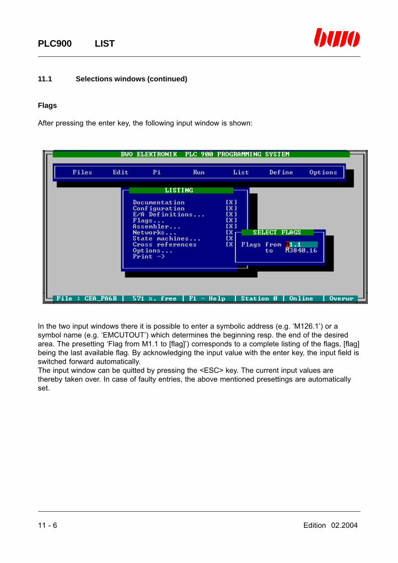
11 - 6 Edition 02.2004
PLC900 LIST
11.1 Selections windows (continued)
Flags
After pressing the enter key, the following input window is shown:
In the two input windows there it is possible to enter a symbolic address (e.g. ‘M126.1’) or asymbol name (e.g. ‘EMCUTOUT’) which determines the beginning resp. the end of the desiredarea. The presetting ‘Flag from M1.1 to [flag]’) corresponds to a complete listing of the flags, [flag]being the last available flag. By acknowledging the input value with the enter key, the input field isswitched forward automatically.The input window can be quitted by pressing the <ESC> key. The current input values arethereby taken over. In case of faulty entries, the above mentioned presettings are automaticallyset.

Edition 02.2004 11 - 7
PLC900 LIST
11.1 Selections windows (continued)
Assembler
After pressing the enter key, the following input window is shown:
In the two input fields, it is possible to enter a program address (sedecimal) or a program labelwhich determines the beginning resp. the end of the desired program part. The presetting ‘from$0000’ ‘to $3FEF’ corresponds to a complete listing of the program. By acknowledging the inputvalue, the input field is automatically changed.The input window can be quitted by pressing the <ESC> key. The current input values arethereby automatically taken over. In case of faulty entries there is automatically set $0000 resp.$3FEF.The listing of all known and unknown labels which is subsequent to the printout of the assembler,only refers to labels that are used in the selected program part.

11 - 8 Edition 02.2004
PLC900 LIST
11.1 Selections windows (continued)
Networks
After pressing the enter key, there is shown a listing of all networks:
The networks are displayed in the order in which they are located in the PLC program. By press-ing the <S> key, the networks are sorted in alphabetical order. Pressing the <S> key once moresorts the networks again in the order they have in the PLC program.Selecting the networks to be printed out is performed by moving the selection bar with the cursorkeys and by pressing the space bar. Al those networks are selected the names of which areshown between the characters ‘<‘ and ‘<‘ .
The following editor functions facilitate the selection:
<M> Select all networks<U> Delete selection (select no network)<I> Invert selection<S> Change order of networks

Edition 02.2004 11 - 9
PLC900 LIST
11.1 Selections windows (continued)
State machines
After pressing the enter key a listing of all state machines is shown:
Selecting the state machines to be printed out is performed by moving the selection bar with thecursor keys and by pressing the space bar. Al those state machines are selected the names ofwhich are shown between the characters ‘<‘ and ‘<‘ .
The following editor functions facilitate the selection:
<M> Select all state machines<U> Delete selection (select no state machine)<I> Invert selection

11 - 10 Edition 02.2004
PLC900 LIST
11.1 Selections windows (continued)
Options
After pressing the enter key, the window for selecting the option is shown:
The following printer options can be activated:
Logic If the function is activated, the networks and state machines are printed asthe type of representation ‘Logic’.
Ladder If the function is activated, the networks and state machines are printed asthe type of representation ‘Ladder’.
Assembler If the function is activated, the networks and state machines are printed asthe type of representation ‘Assembler’.
High-speed printing If the function is activated, printing is performed in the mode ‘Fast print’.
Print to file If the function is activated, printing is not performed on the connectedprinter, but to a file. The created file has the name
[filename].PRN
[filename] being identical with the name of the PLC900 program file. Thefile is in the directory that has been indicated as the printing directory ofthe PLC 900 in the file PLC900.CFG, subsequently e.g.‘C:\PLC900\PRINT’. A PRN file created in that manner can later be typedout to the printer by means of the DOS instruction ‘PRINT’.

Edition 02.2004 11 - 11
PLC900 LIST
11.2 Layout of the listing
The printout of a PLC900 program can be performed in two ways as a matter of principle:
Standard printing

11 - 12 Edition 02.2004
PLC900 LIST
11.2 Layout of the listing (continued)
High-speed printing

Edition 02.2004 11 - 13
PLC900 LIST
11.2 Layout of the listing (continued)
The heading line of each page can be varied by the user:
The contents of the heading line is automatically taken over by the PLC900 system from a text filethat can be created and processed by means of each DOS editor. The length of the text is arbi-trary. The name of the text file must be
[filename].HDR
[filename] being identical with the name of the PLC900 program file. The text file has to be in thedirectory that has been indicated as the printing directory of the PLC 900 in the file PLC900.CFG,subsequently e.g. ‘C:\PLC900\PRINT’. If the file does not exist, a standard text is inserted.
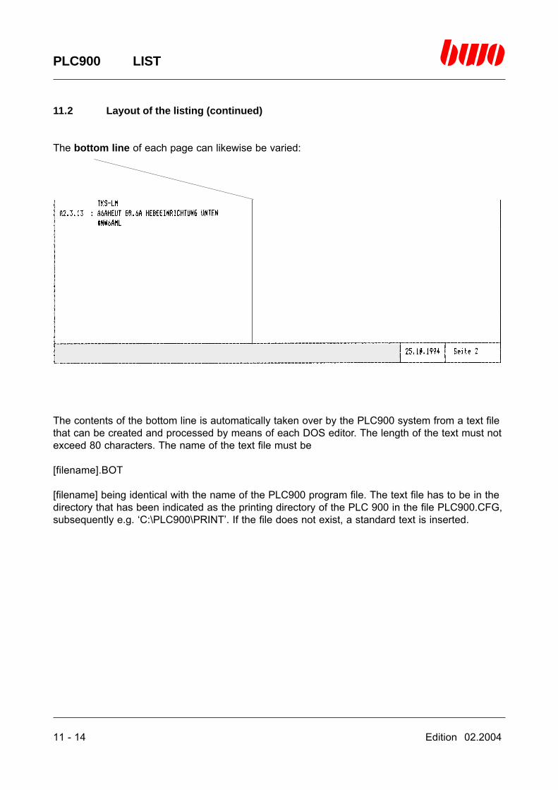
11 - 14 Edition 02.2004
PLC900 LIST
11.2 Layout of the listing (continued)
The bottom line of each page can likewise be varied:
The contents of the bottom line is automatically taken over by the PLC900 system from a text filethat can be created and processed by means of each DOS editor. The length of the text must notexceed 80 characters. The name of the text file must be
[filename].BOT
[filename] being identical with the name of the PLC900 program file. The text file has to be in thedirectory that has been indicated as the printing directory of the PLC 900 in the file PLC900.CFG,subsequently e.g. ‘C:\PLC900\PRINT’. If the file does not exist, a standard text is inserted.
Edition 02.2004 11 - 15
PLC900 LIST
11.2 Layout of the listing (continued)
Notice: In the printout of the PLC900 system there are used ASCII characters having a charactervalue exceeding 127. This can lead to misinterpretations of the printer data as to various printertypes, i.e. there are inserted improper additional characters instead of the semigraphical charac-ters. Under normal circumstances, each printer can be switched to a semigraphical character set.If switching to it is only possible with high efforts the problem may be solved as follows:
Select ‘OPTIONS/Fast print’Select ‘OPTIONS/Print to file’Start printingQuit the PLC 900Start the conversion program PLCCONV.EXE.
PLCCONV.EXE is located in the directory s. The program converts all semigraphical characters tocorresponding replacement characters and creates a file having the name
[filename].TXT
‘[filename]’ being the name of the PLC900 program file. This file can be typed out to the printer bymeans of the DOS instruction ‘PRINT’.
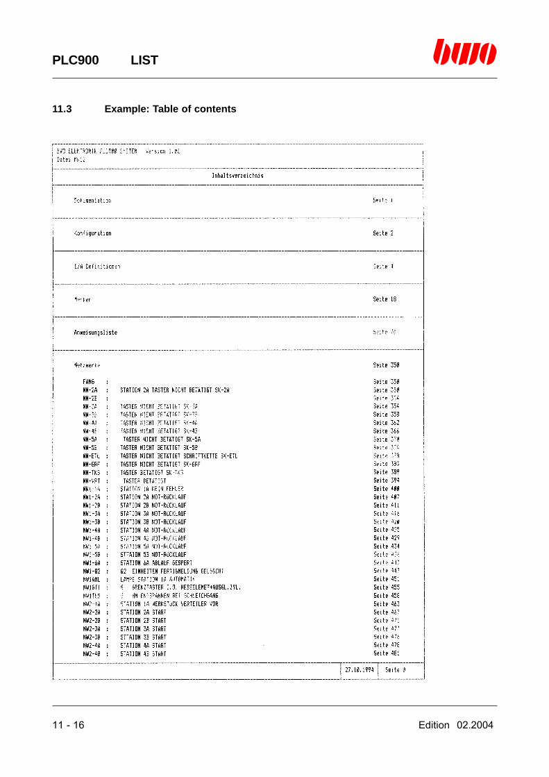
11 - 16 Edition 02.2004
PLC900 LIST
11.3 Example: Table of contents

Edition 02.2004 11 - 17
PLC900 LIST
11.3 Example: Documentation

11 - 18 Edition 02.2004
PLC900 LIST
11.3 Example: Configuration
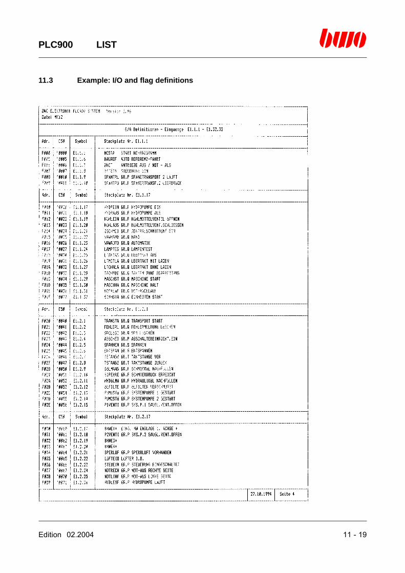
Edition 02.2004 11 - 19
PLC900 LIST
11.3 Example: I/O and flag definitions
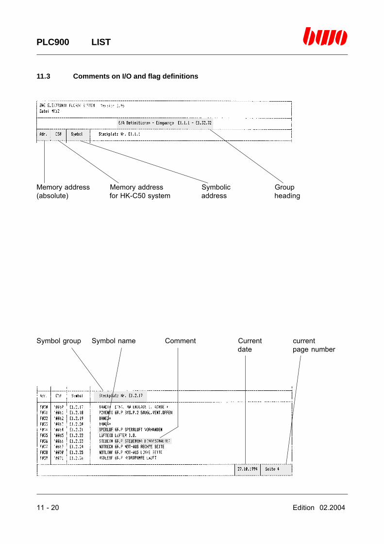
11 - 20 Edition 02.2004
PLC900 LIST
11.3 Comments on I/O and flag definitions
Memory address Memory address Symbolic Group(absolute) for HK-C50 system address heading
Symbol group Symbol name Comment Current currentdate page number
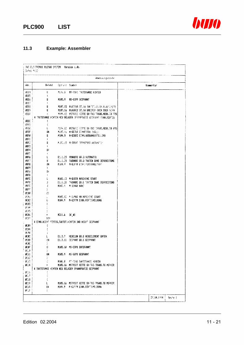
Edition 02.2004 11 - 21
PLC900 LIST
11.3 Example: Assembler

11 - 22 Edition 02.2004
PLC900 LIST
11.3 Comments on the assembler
Program address Group heading Line comment
Program Current date Current page number

Edition 02.2004 11 - 23
PLC900 LIST
11.3 Example: Cross-referencing assembler

11 - 24 Edition 02.2004
PLC900 LIST
11.3 Example: Networks (Ladder)

Edition 02.2004 11 - 25
PLC900 LIST
11.3 Comments on networks
Cross references for network Network Group heading
Symbolic Symbol name Address / label Comment Address / labeladdress where the symbol where the symbol
is affected is used(*-marking)
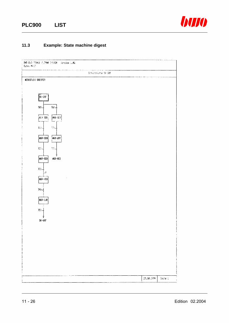
11 - 26 Edition 02.2004
PLC900 LIST
11.3 Example: State machine digest
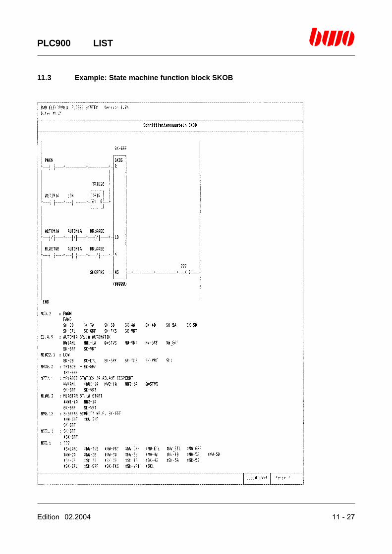
Edition 02.2004 11 - 27
PLC900 LIST
11.3 Example: State machine function block SKOB
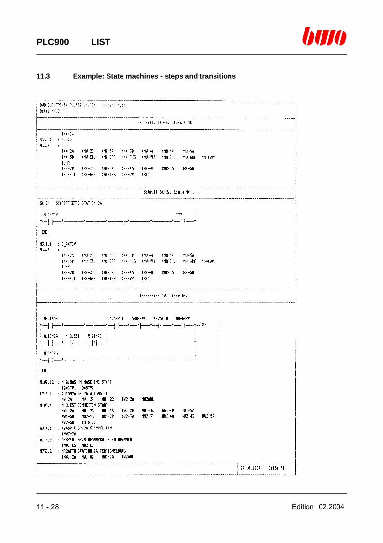
11 - 28 Edition 02.2004
PLC900 LIST
11.3 Example: State machines - steps and transitions

Edition 02.2004 11 - 29
PLC900 LIST
11.3 Example: Cross reference networks / state machines

11 - 30 Edition 02.2004
PLC900 LIST
11.3 Comments on the cross references
Symbolic Symbol Comment Group headingaddress name
Address / label Address / label Current Currentwhere the symbol where the symbol date page numberis used is affected (*-marking)
Edition 02.2004 12 - 1
PLC900 DEFINE
12. Menu Define
12.1 Symbol definitions 12 - 3
12.2 Storage organization 12 - 5
12.3 System control block 12 - 7
12.4 Symbol editor 12 - 8
⌧
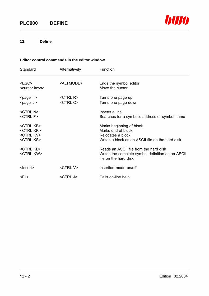
12 - 2 Edition 02.2004
PLC900 DEFINE
12. Define
Editor control commands in the editor window
Standard Alternatively Function
<ESC> <ALTMODE> Ends the symbol editor<cursor keys> Move the cursor
<page ↑> <CTRL R> Turns one page up<page ↓> <CTRL C> Turns one page down
<CTRL N> Inserts a line<CTRL F> Searches for a symbolic address or symbol name
<CTRL KB> Marks beginning of block<CTRL KK> Marks end of block<CTRL KV> Relocates a block<CTRL KS> Writes a block as an ASCII file on the hard disk
<CTRL KL> Reads an ASCII file from the hard disk<CTRL KW> Writes the complete symbol definition as an ASCII
file on the hard disk
<Insert> <CTRL V> Insertion mode on/off
<F1> <CTRL J> Calls on-line help
Edition 02.2004 12 - 3
PLC900 DEFINE
12.1 Symbol definitions
The PLC900 programming system offers three different possibilities of addressing the memory ofthe central unit and inputs and outputs. Addressing can be performed by means of symbolicaddresses or symbol names besides the actual (absolute) address.
Absolute addressing
Representation of the address as a decimal number.Example: 528
Representation of the address as a sedecimal number. Identification of the sedecimal representa-tion is provided by prefixing the character ‘$’.Example: $210 (=528)
Representation of the address as an octal number. Identification of the octal representation isprovided by prefixing the character ‘0’ or ‘ ’ ’ .Example: ‘1020(=528)
For the purpose of applying the absolute addressing, it is recommended to use the sedecimalrepresentation since it can easily be transferred to the storage organization (base of 16).
Symbolic addressing
When using the symbolic addressing, the desired memory address resp. the desired input oroutput is represented by an easily understandable close-to-the-system combination of letters andnumbers. Representing addresses is performed according to the following definitions:
General definition of symbolic addresses
Symbolic address Example
Flag M[g].[n] M1.2, M2.5
Input I[st].[sl].[e] I1.3.17, I1.6.22
Output O[st].[sl].[a] O1.1.9, O1.4.11

12 - 4 Edition 02.2004
PLC900 DEFINE
12.1 Symbol definitions (continued)
Additional definitions of the symbolic addresses in the BWONET
Symbolic address Example
Flag M[st].[g].[n] M1.2.8, M2.4.1
Input I[st].[sl].[e] I2.3.17, I3.6.22
Output O[st].[sl].[a] O2.1.9, O3.4.11
[g] = Group number (1..3840)[n] = Bit or register number (1..16)[st] = Station number (1..255)[sl] = Slot number (1..32)[e] = Input number (1..32)[a] = Output number (1..32)
Symbol name
A symbol name represents a convenient abbreviation for using a flag, input or output. Exactly onesymbol name in the PLC900 system can belong to each physical address. On the contrary, it is,however, possible that physical addresses of any number belong to one symbol name whenusing the keyword ‘DUP_SYMBOLS : N’ in the configuration file PLC900.CFG.
Definitions for symbol names
The length of a symbol name must not exceed seven characters. There are valid all ASCIIcharacters with the exception of the following characters:
- ASCII character less than #33 (corresponds to ‘!’) in the first place- ‘ . ‘ in any place (identification for symbolic addresses)- ‘$’ in the first place (identification for sedecimal numbers)- ‘0’ or ‘ ‘ ‘ in the first place (identification for octal numbers)- ‘%’ in the first place (identification for indirect addressing in LADDER and LOGIC)- ‘+’ in the first place- ‘ , ‘ in the first place- ‘ - ‘ in the first place- ‘1’ to ‘9’ in the first place- ‘@’ in the first place (identification for CALL instructions)
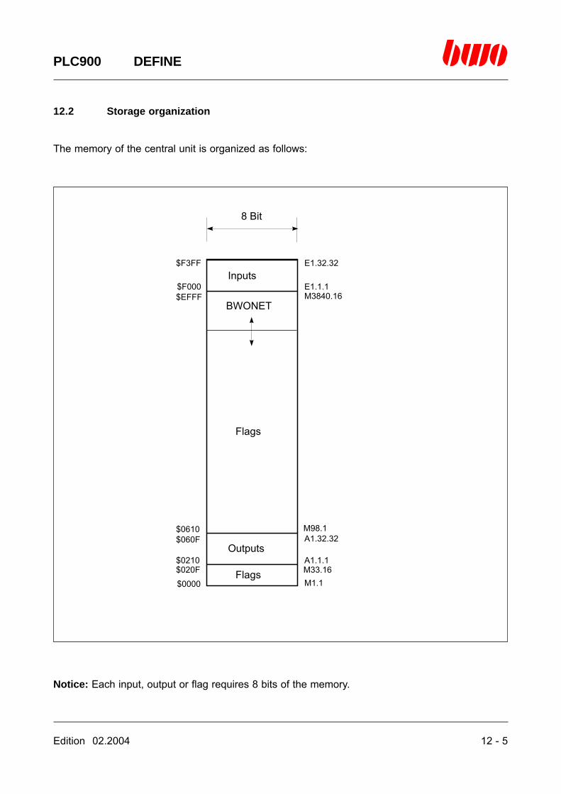
Edition 02.2004 12 - 5
PLC900 DEFINE
12.2 Storage organization
The memory of the central unit is organized as follows:
Notice: Each input, output or flag requires 8 bits of the memory.
8 Bit
Inputs
BWONET
Flags
Outputs
Flags
E1.32.32
E1.1.1M3840.16
M98.1A1.32.32
A1.1.1M33.16M1.1$0000
$020F
$060F$0610
$0210
$F3FF
$F000$EFFF
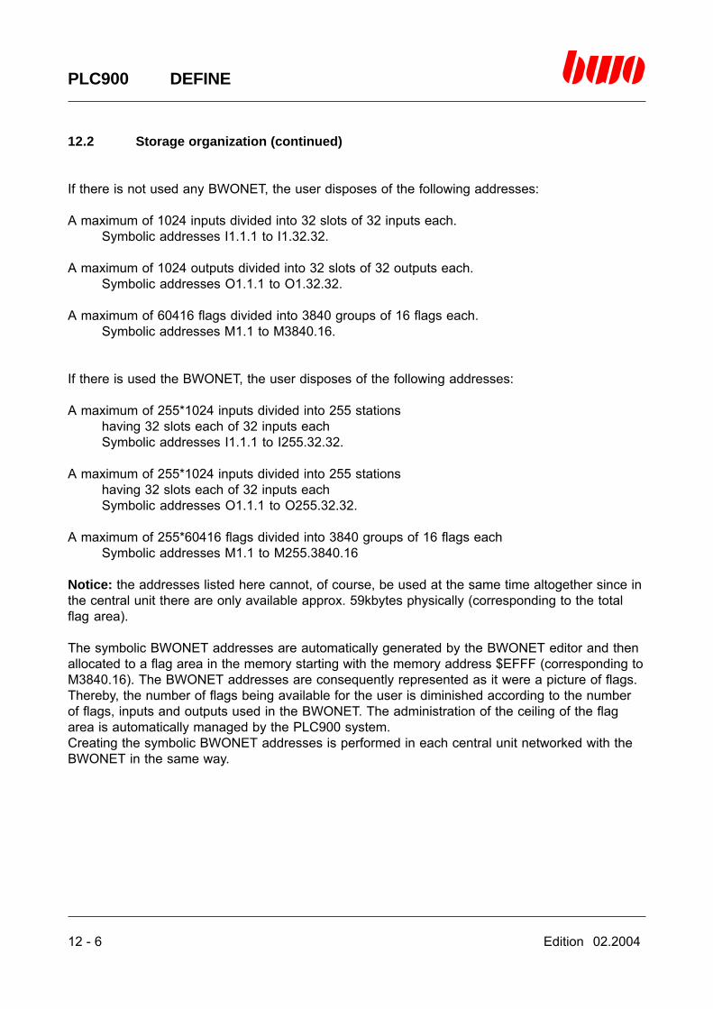
12 - 6 Edition 02.2004
PLC900 DEFINE
12.2 Storage organization (continued)
If there is not used any BWONET, the user disposes of the following addresses:
A maximum of 1024 inputs divided into 32 slots of 32 inputs each.Symbolic addresses I1.1.1 to I1.32.32.
A maximum of 1024 outputs divided into 32 slots of 32 outputs each.Symbolic addresses O1.1.1 to O1.32.32.
A maximum of 60416 flags divided into 3840 groups of 16 flags each.Symbolic addresses M1.1 to M3840.16.
If there is used the BWONET, the user disposes of the following addresses:
A maximum of 255*1024 inputs divided into 255 stationshaving 32 slots each of 32 inputs eachSymbolic addresses I1.1.1 to I255.32.32.
A maximum of 255*1024 inputs divided into 255 stationshaving 32 slots each of 32 inputs eachSymbolic addresses O1.1.1 to O255.32.32.
A maximum of 255*60416 flags divided into 3840 groups of 16 flags eachSymbolic addresses M1.1 to M255.3840.16
Notice: the addresses listed here cannot, of course, be used at the same time altogether since inthe central unit there are only available approx. 59kbytes physically (corresponding to the totalflag area).
The symbolic BWONET addresses are automatically generated by the BWONET editor and thenallocated to a flag area in the memory starting with the memory address $EFFF (corresponding toM3840.16). The BWONET addresses are consequently represented as it were a picture of flags.Thereby, the number of flags being available for the user is diminished according to the numberof flags, inputs and outputs used in the BWONET. The administration of the ceiling of the flagarea is automatically managed by the PLC900 system.Creating the symbolic BWONET addresses is performed in each central unit networked with theBWONET in the same way.

Edition 02.2004 12 - 7
PLC900 DEFINE
12.3 System control block
$200 M33.1 CNC interrupt1 if an interrupt has been released by the CNC.Has to be deleted in the program again.
$201 M33.2 Watch-dog control register0: watch-dog active$5A: watch-dog inactive
$202 M33.3 Power-on flag.After switching on the PLC, the flag is set to 1.
$203 M33.4 Reserved (POS modules)
$204 M33.5 = 1 In case of division by 0.Has to be deleted in the program again.
$205 M33.6 Reserved$206 M33.7 Reserved$207 M33.8 Reserved$208 M33.9 Reserved$209 M33.10 Test modules (for TOS registers)
On = H, Off = L
$20A, $20B M33.11 Pointer to the first software timer
$20C, $20D M33.13 Number of timers
$20E M33.15 Cycle time in steps of 5 ms
$20F M33.16 Flag for deleting the watch-dog.Has to be deleted in each program run.
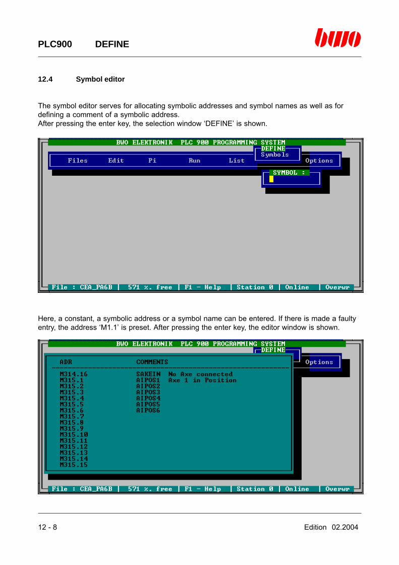
12 - 8 Edition 02.2004
PLC900 DEFINE
12.4 Symbol editor
The symbol editor serves for allocating symbolic addresses and symbol names as well as fordefining a comment of a symbolic address.After pressing the enter key, the selection window ‘DEFINE’ is shown.
Here, a constant, a symbolic address or a symbol name can be entered. If there is made a faultyentry, the address ‘M1.1’ is preset. After pressing the enter key, the editor window is shown.

Edition 02.2004 12 - 9
PLC900 DEFINE
12.4 Symbol editor (continued)
The symbolic addresses are listed in the left column in groups of 16 addresses each. In the rightcolumn there can be entered a text that is interpreted by the PLC900 system according to thefollowing pattern:
The first seven characters and the characters till the first blank character are interpreted as asymbol name.
Each character, starting with the eighth character of the text or the first character behind the firstblank character of the text, is interpreted as a comment.
If the first character of the text is a blank character, the symbolic address has no symbol name buta comment instead.
If a symbol name is entered twice and the keyword ‘DUP_SYMBOLS:Y’ is located in the filePLC900.CFG the following error message is shown:
The symbol name entered twice is automatically deleted.

12 - 10 Edition 02.2004
PLC900 DEFINE
12.4 Symbol editor (continued)
Changing the wiring
Inserting, deleting and relocating operations in the editor window can be performed by means ofthe editor control commands. In case there are deleted symbol names that are used in the pro-gram, those names have to be deleted from the program first. Otherwise the following message isshown:
Inserting, deleting and relocating operations can only be performed within the following ranges:
Flags:
from M1.1 till M32.16from M33.1 till M33.16from M98.1 till M3840.16
Inputs and outputs: by one slot each.
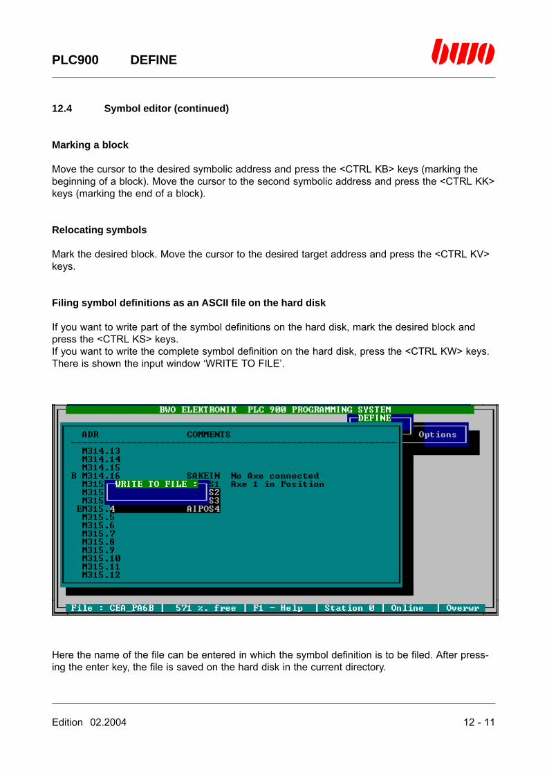
Edition 02.2004 12 - 11
PLC900 DEFINE
12.4 Symbol editor (continued)
Marking a block
Move the cursor to the desired symbolic address and press the <CTRL KB> keys (marking thebeginning of a block). Move the cursor to the second symbolic address and press the <CTRL KK>keys (marking the end of a block).
Relocating symbols
Mark the desired block. Move the cursor to the desired target address and press the <CTRL KV>keys.
Filing symbol definitions as an ASCII file on the hard disk
If you want to write part of the symbol definitions on the hard disk, mark the desired block andpress the <CTRL KS> keys.If you want to write the complete symbol definition on the hard disk, press the <CTRL KW> keys.There is shown the input window ‘WRITE TO FILE’.
Here the name of the file can be entered in which the symbol definition is to be filed. After press-ing the enter key, the file is saved on the hard disk in the current directory.
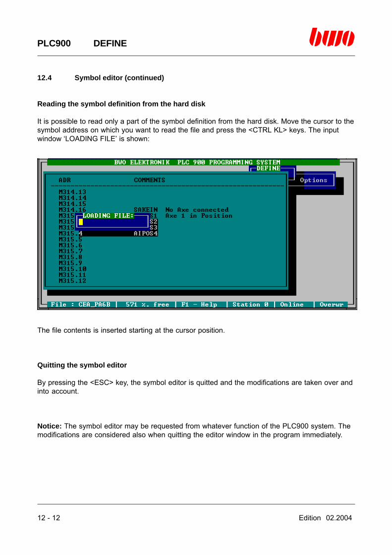
12 - 12 Edition 02.2004
PLC900 DEFINE
12.4 Symbol editor (continued)
Reading the symbol definition from the hard disk
It is possible to read only a part of the symbol definition from the hard disk. Move the cursor to thesymbol address on which you want to read the file and press the <CTRL KL> keys. The inputwindow ‘LOADING FILE’ is shown:
The file contents is inserted starting at the cursor position.
Quitting the symbol editor
By pressing the <ESC> key, the symbol editor is quitted and the modifications are taken over andinto account.
Notice: The symbol editor may be requested from whatever function of the PLC900 system. Themodifications are considered also when quitting the editor window in the program immediately.
Edition 02.2004 13 - 1
PLC900 OPTIONS
13. Menu Options
13.1 Online/Offline 13 - 3
13.2 Keyword 13 - 4
13.3 Ladder/Logic 13 - 6
13.4 Terminal 13 - 7
13.5 Netid 13 -14
⌧
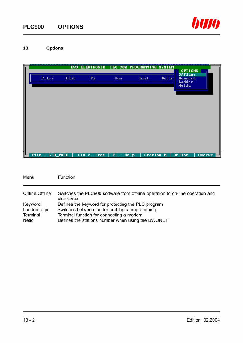
13 - 2 Edition 02.2004
PLC900 OPTIONS
13. Options
Menu Function
Online/Offline Switches the PLC900 software from off-line operation to on-line operation andvice versa
Keyword Defines the keyword for protecting the PLC programLadder/Logic Switches between ladder and logic programmingTerminal Terminal function for connecting a modemNetid Defines the stations number when using the BWONET

Edition 02.2004 13 - 3
PLC900 OPTIONS
13.1 Online/Offline
Switches between the operating modes on-line and off-line. There is always displayed theexecutable function, i.e. when the programming system is in on-line mode, the function off-line isoffered in the menu. When the programming system is in off-line mode, the function on-line isoffered.
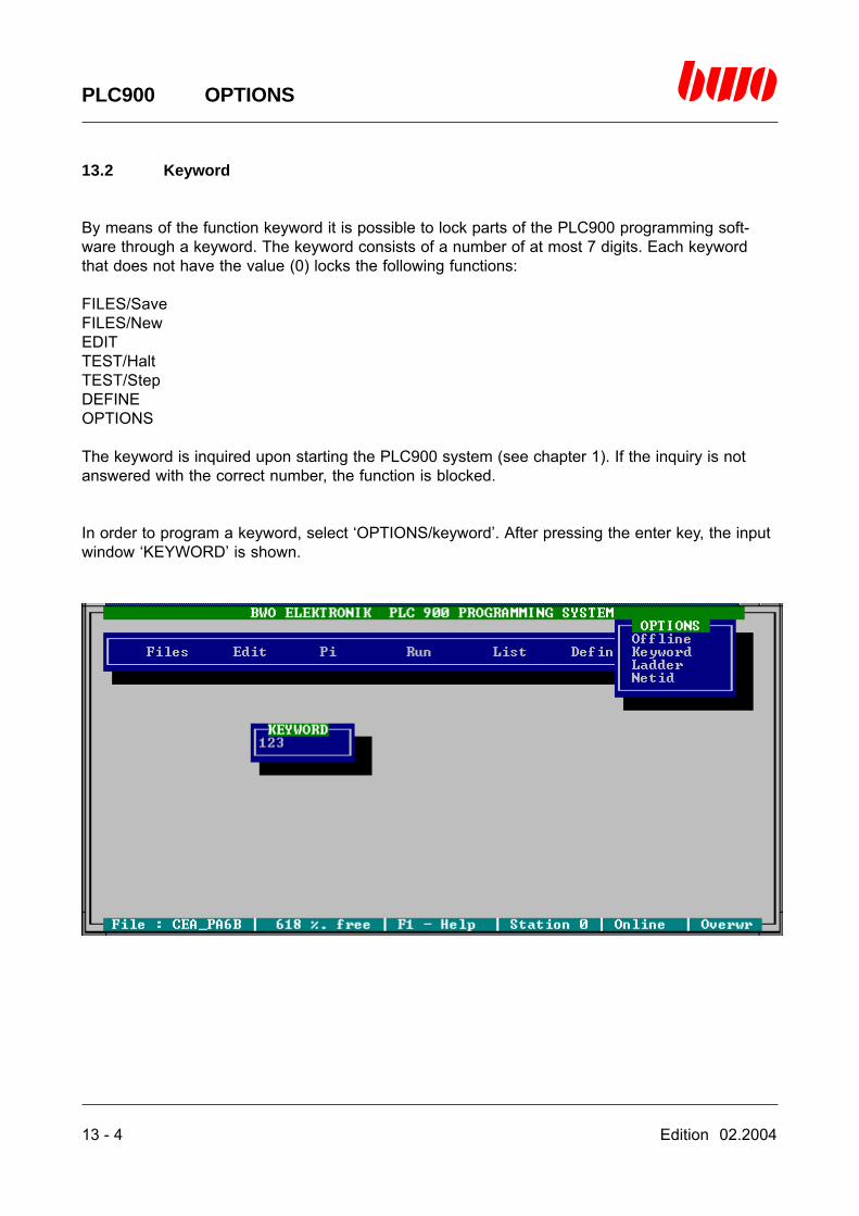
13 - 4 Edition 02.2004
PLC900 OPTIONS
13.2 Keyword
By means of the function keyword it is possible to lock parts of the PLC900 programming soft-ware through a keyword. The keyword consists of a number of at most 7 digits. Each keywordthat does not have the value (0) locks the following functions:
FILES/SaveFILES/NewEDITTEST/HaltTEST/StepDEFINEOPTIONS
The keyword is inquired upon starting the PLC900 system (see chapter 1). If the inquiry is notanswered with the correct number, the function is blocked.
In order to program a keyword, select ‘OPTIONS/keyword’. After pressing the enter key, the inputwindow ‘KEYWORD’ is shown.

Edition 02.2004 13 - 5
PLC900 OPTIONS
13.2 Keyword (continued)
The keyword is saved by means of the function ‘FILES/Save/Eeprom’ in the EEPROM of thecentral unit. Upon starting the PLC900 software next time, the keyword is activated.
The keyword can only be deleted if it is known since the function ‘OPTIONS’ is likewise lockedthrough the keyword.Delete the keyword in the input window ‘KEYWORD’ by entering zero (0) and saving the programanew in the EEPROM of the central unit.
Notice: If the keyword is unknown, please contact BWO ELEKTRONIK, department TechnicalSales.

13 - 6 Edition 02.2004
PLC900 OPTIONS
13.3 Ladder/Logic
Switches the network editor from ladder programming to logic programming and vice versa. Thereis always displayed the executable function, i.e. if ladder programming has been selected, thefunction Logic is offered in the menu. If logic programming has been selected, the function Lad-der is offered in the menu.

Edition 02.2004 13 - 7
PLC900 OPTIONS
13.4 Terminal
The terminal function of the PLC900 system allows for connecting a central unit that is installed ina separated place via a modem and the telephone line. There are backed all of the functions ofthe PLC900 software by the terminal. Therefore, both ‘Remote diagnosis’ and ‘Teleprogramming’are possible for a control device.
A further facility of the terminal consists in connecting two programming devices by means ofconnected modems. A condition for it is that there is the PLC900 software available in bothprogramming devices. By this means, the remote data transmission is rendered possible.
ooooo
oo
oo 1
5
6
9
oooo
o
oooo
1
5
6
9
ooooo
oo
oo
1
5
6
9
CEA083543
1011
12131415
16
9
Bed
ien
feld
Ver
net
zun
gP
rog
. Ger
ät
o
ooo
oooo
o
1718
20 212223
24
19
0V24V
12
4 567
8
3
24V0V
ooo
oooo
o
oo
ooooo
o
ST
●
●
●
●
●
●
●
●
●
●
●
●
●
●
●
●
●
●
●
●
●
●
●
●
●
●
●
●
●
●
●
●
●
●
●
●
●
●
●
●
●
●
●
●
●
●
●
●
●
●
●
●
●
●
●
●
●
●
●
●
AEK083539
12
4 567
8
3
0V
101112
13141516
0V
18
24V0V
24V0V
9
17
1920
21222324
2526272829
303132
oooo
oooo
ooo
oooo
o
ooooo
ooo
oooo
oooo
●
●
●
●
●
●
●
●
●
●
ooooo
oooo
1
5
o
ooooo
10
11 6
oo
ooo
oooo
1
5
o
oo
ooo
10
11 6
ooooo
oooo
1
5
o
ooooo
10
11 6
POS083545
S1+S1-
S2+S2-
R1+
R2+R3+
S3+S3-
R-
MT3+
MT-
Mes
s 1
Mes
s 2
Mes
s 3
Ser
vice
●
●
●
●
●
●
●
●
●
●
●
●
●
●
●
●
●
●
●
●
o
oooo
oooo
1
5
6
9
MT1+MT2+
ooooo
oooo
1
5
o
ooooo
10
11 6
oo
ooo
oooo
1
5
o
oo
ooo
10
11 6
ooooo
oooo
1
5
o
ooooo
10
11 6
POS083545
S1+S1-
S2+S2-
R1+
R2+R3+
S3+S3-
R-
MT3+
MT-
Mes
s 1
Mes
s 2
Mes
s 3
Ser
vice
●
●
●
●
●
●
●
●
●
●
●
●
●
●
●
●
●
●
●
●
o
oooo
oooo
1
5
6
9
MT1+MT2+
programming unit controlconverter set 20mA / V24article no. 083840
modemmodem
telephon line
programming unit programming unit
modemmodem
telephon line

13 - 8 Edition 02.2004
PLC900 OPTIONS
13.4 Terminal (continued)
Activating the terminal functions
First, the keyword ‘MODEM:Y’ has to be entered into the file PLC900.CFG. Upon starting thePLC900 system, the interface indicated together with the keyword ‘COM’ is recognized as themodem interface. The programming system remains, nevertheless, in off-line mode.
Connecting a control device that is installed in a separate place
Select the function ‘OPTIONS/Online’ and press the enter key. There is shown the input window‘TELEPHONE NUMBER’:
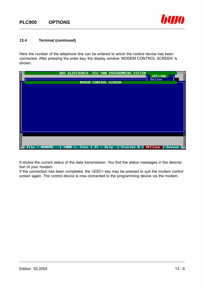
Edition 02.2004 13 - 9
PLC900 OPTIONS
13.4 Terminal (continued)
Here the number of the telephone line can be entered to which the control device has beenconnected. After pressing the enter key, the display window ‘MODEM CONTROL SCREEN’ isshown:
It shows the current status of the data transmission. You find the status messages in the descrip-tion of your modem.If the connection has been completed, the <ESC> key may be pressed to quit the modem controlscreen again. The control device is now connected to the programming device via the modem.
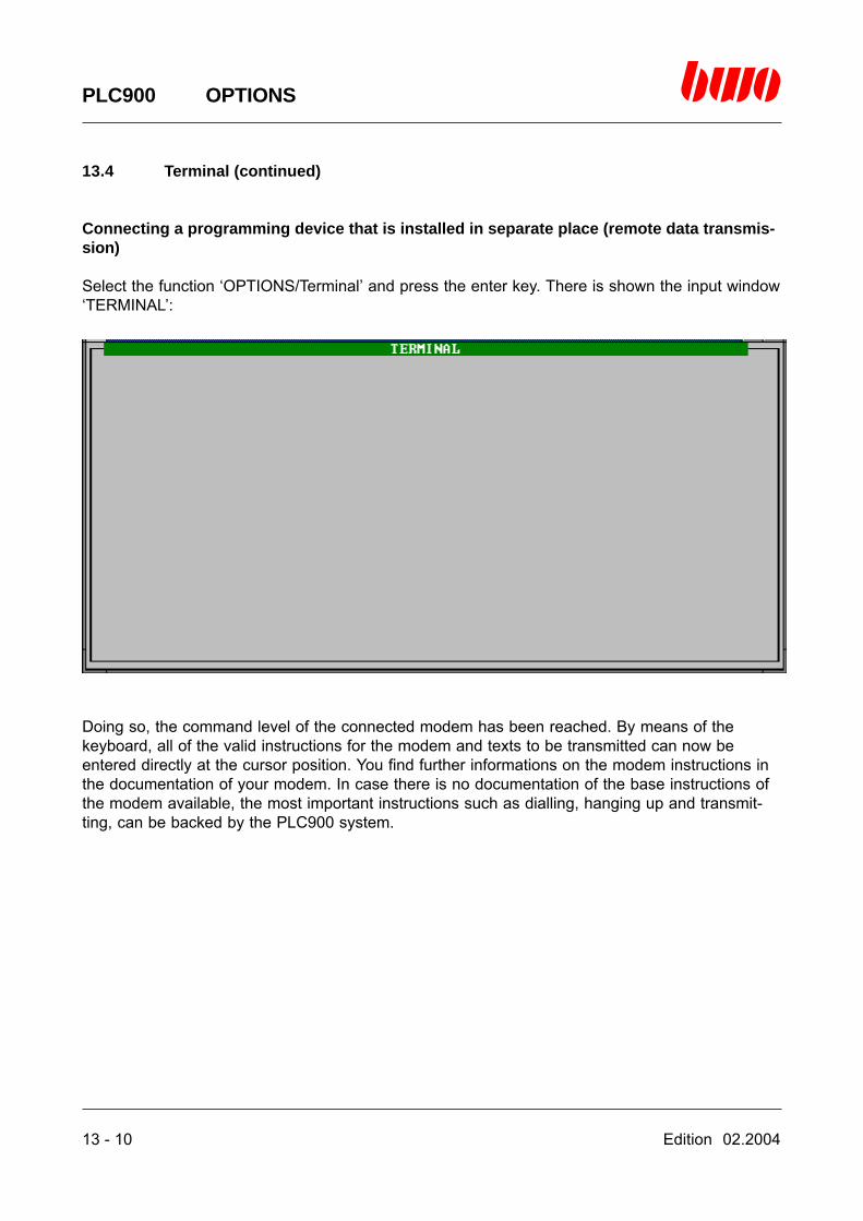
13 - 10 Edition 02.2004
PLC900 OPTIONS
13.4 Terminal (continued)
Connecting a programming device that is installed in separate place (remote data transmis-sion)
Select the function ‘OPTIONS/Terminal’ and press the enter key. There is shown the input window‘TERMINAL’:
Doing so, the command level of the connected modem has been reached. By means of thekeyboard, all of the valid instructions for the modem and texts to be transmitted can now beentered directly at the cursor position. You find further informations on the modem instructions inthe documentation of your modem. In case there is no documentation of the base instructions ofthe modem available, the most important instructions such as dialling, hanging up and transmit-ting, can be backed by the PLC900 system.

Edition 02.2004 13 - 11
PLC900 OPTIONS
13.4 Terminal (continued)
By pressing the <ESC> key, the following submenu is reached:
Menu Function
Quit Truncates the terminal functionCall Dialling function of the modemHangup Hanging-up function of the modemSendfile Sends a fileRecfile Records a file
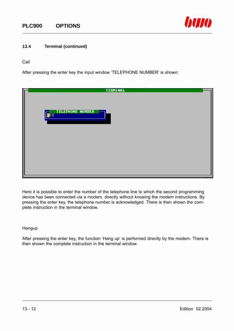
13 - 12 Edition 02.2004
PLC900 OPTIONS
13.4 Terminal (continued)
Call
After pressing the enter key the input window ‘TELEPHONE NUMBER’ is shown:
Here it is possible to enter the number of the telephone line to which the second programmingdevice has been connected via a modem, directly without knowing the modem instructions. Bypressing the enter key, the telephone number is acknowledged. There is then shown the com-plete instruction in the terminal window.
Hangup
After pressing the enter key, the function ‘Hang up’ is performed directly by the modem. There isthen shown the complete instruction in the terminal window.
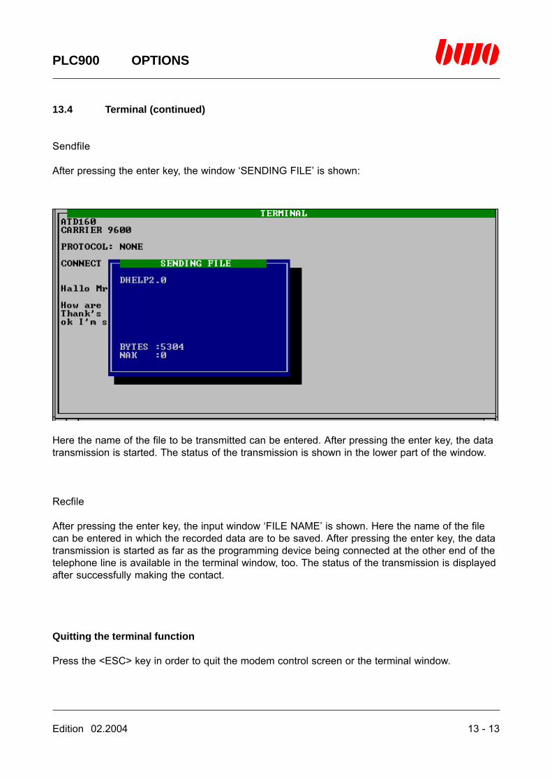
Edition 02.2004 13 - 13
PLC900 OPTIONS
13.4 Terminal (continued)
Sendfile
After pressing the enter key, the window ‘SENDING FILE’ is shown:
Here the name of the file to be transmitted can be entered. After pressing the enter key, the datatransmission is started. The status of the transmission is shown in the lower part of the window.
Recfile
After pressing the enter key, the input window ‘FILE NAME’ is shown. Here the name of the filecan be entered in which the recorded data are to be saved. After pressing the enter key, the datatransmission is started as far as the programming device being connected at the other end of thetelephone line is available in the terminal window, too. The status of the transmission is displayedafter successfully making the contact.
Quitting the terminal function
Press the <ESC> key in order to quit the modem control screen or the terminal window.
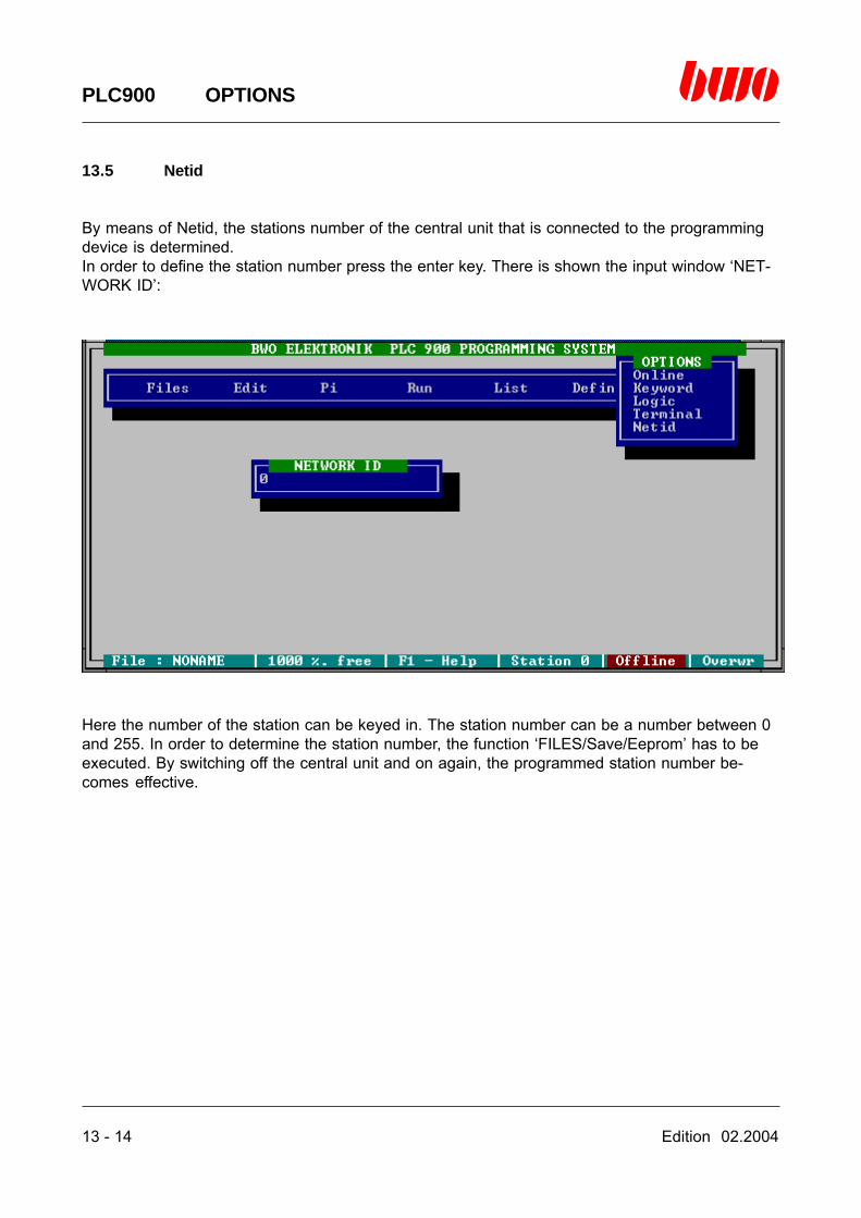
13 - 14 Edition 02.2004
PLC900 OPTIONS
13.5 Netid
By means of Netid, the stations number of the central unit that is connected to the programmingdevice is determined.In order to define the station number press the enter key. There is shown the input window ‘NET-WORK ID’:
Here the number of the station can be keyed in. The station number can be a number between 0and 255. In order to determine the station number, the function ‘FILES/Save/Eeprom’ has to beexecuted. By switching off the central unit and on again, the programmed station number be-comes effective.