platform rex 5xx terminals (english - pdf - data sheet) · signal processing module (spm) module...
TRANSCRIPT

1MRK 580 063-BEN
Page 1
Revision: AIssued: March 2003Data subject to change without notice
• Available in 1/4, 3/4 or full 19" widths.
• IP 40 environmental protection graded.
• Available in IP 54 version for increased environmental protection
• Rack, flush, semiflush or wall mounted.
• Side-by-side mounting possible for multiple module arrangements.
• Built-in human machine interface.
• Well proven, always included features
- Self-supervision with internal event recorder
- Real-time clock
- Selectable time synchronisation source
- Four independent groups of complete setting parameters
- Setting lockout function
- Logic function blocks
- Event function
- I/O-system configurator
- Blocking of signals during test
- Monitoring functions with settable alarm levels
- Measured values available locally and remotely
• Carefully designed hardware fullfills strin-gent EMC requirements
• Flexible hardware allows configuration to each user’s specific needs
• The platform is prepared for communica-tion with local PC
The platform hardware and common software functions are included for all REx 5xx termi-nals. It is the foundation on which all termi-
nals are built. Application specific modules and functions are added to create a specific terminal type or family.
The REx 5xx platform consists of a case, hardware modules and a set of basic func-tions.
The closed and partly welded steel case makes it possible to fulfill stringent EMC requirements. Three different sizes of the case are available to fulfill the space require-ments of different terminals. The degree of protection is IP 40 according to IEC 529 for cases with the widths 1/2x19” and 3/4x19”. For case size 1/1x19” IP 30 applies for the top and bottom part. IP 54 can be obtained for the front area in flush and semiflush applica-tions. Mounting kits are available for rack, flush, semiflush or wall mounting.
All connections are made on the rear of the case. Screw compression type terminal blocks are used for electrical connections. Serial communication connections are made by optical fibre connectors type Hewlett Packard (HFBR) for plastic fibres or bayonet type ST for glass fibres.
A set of hardware modules are always included in a terminal. Application specific modules are added to create a specific termi-nal type or family.
The basic functions provide a terminal with basic functionality such as self supervision, I/O-system configurator, real time clock and other functions to support the protection and control system of a terminal.
1MRK 580 063-BEN
Page 2
!"# !
$
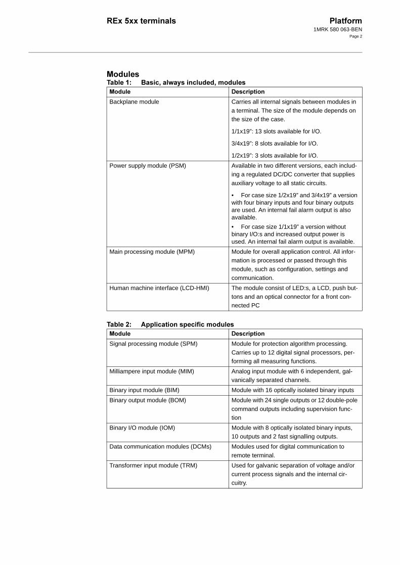
Backplane module Carries all internal signals between modules in
a terminal. The size of the module depends on the size of the case.
1/1x19”: 13 slots available for I/O.
3/4x19”: 8 slots available for I/O.
1/2x19”: 3 slots available for I/O.
Power supply module (PSM) Available in two different versions, each includ-ing a regulated DC/DC converter that supplies
auxiliary voltage to all static circuits.
• For case size 1/2x19” and 3/4x19” a version with four binary inputs and four binary outputs are used. An internal fail alarm output is also available.
• For case size 1/1x19” a version without binary I/O:s and increased output power is used. An internal fail alarm output is available.
Main processing module (MPM) Module for overall application control. All infor-mation is processed or passed through this module, such as configuration, settings and
communication.
Human machine interface (LCD-HMI) The module consist of LED:s, a LCD, push but-tons and an optical connector for a front con-nected PC
Signal processing module (SPM) Module for protection algorithm processing.
Carries up to 12 digital signal processors, per-forming all measuring functions.
Milliampere input module (MIM) Analog input module with 6 independent, gal-vanically separated channels.
Binary input module (BIM) Module with 16 optically isolated binary inputs
Binary output module (BOM) Module with 24 single outputs or 12 double-pole
command outputs including supervision func-tion
Binary I/O module (IOM) Module with 8 optically isolated binary inputs, 10 outputs and 2 fast signalling outputs.
Data communication modules (DCMs) Modules used for digital communication to
remote terminal.
Transformer input module (TRM) Used for galvanic separation of voltage and/or current process signals and the internal cir-cuitry.

1MRK 580 063-BEN
Page 3
%#
Figure 1: Hardware structure of the full width 19” case
A/D conversion module (ADM) Used for analog to digital conversion of analog
process signals galvanically separated by the TRM.
Optical receiver module (ORM) Used to interface process signals from optical
instrument transformers.
Serial communication module (SCM) Used for SPA/LON/IEC communication
:
1MRK 580 063-BEN
Page 4
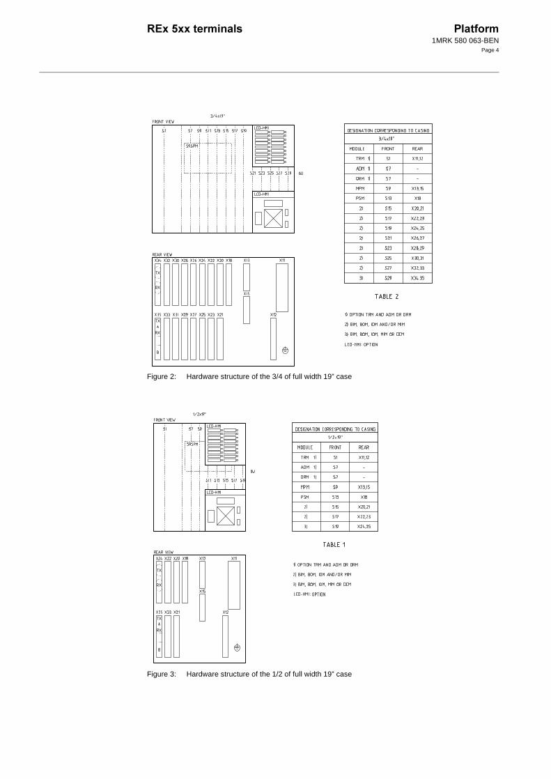
Figure 2: Hardware structure of the 3/4 of full width 19” case
Figure 3: Hardware structure of the 1/2 of full width 19” case
:
:

1MRK 580 063-BEN
Page 5
! "& '
Figure 4: Case without rear cover
Figure 5: Case without rear cover with 19” rack mounting kit
A
B C
D
E
xx02000646.vsd
F
GH
J
K
xx02000647.vsd
( ) ( * + ,
6U, 1/2 x 19”
265.9
223.7 205.7
190.5
203.7 - -
6U, 3/4 x 19” 336 204.1 252.9 318 316 - 186.6 -
6U, 1/1 x 19” 448.3 430.3 428.3 465.1 482.6
The H and K dimensions are defined by the 19” rack mounting kit
(mm)
1MRK 580 063-BEN
Page 6
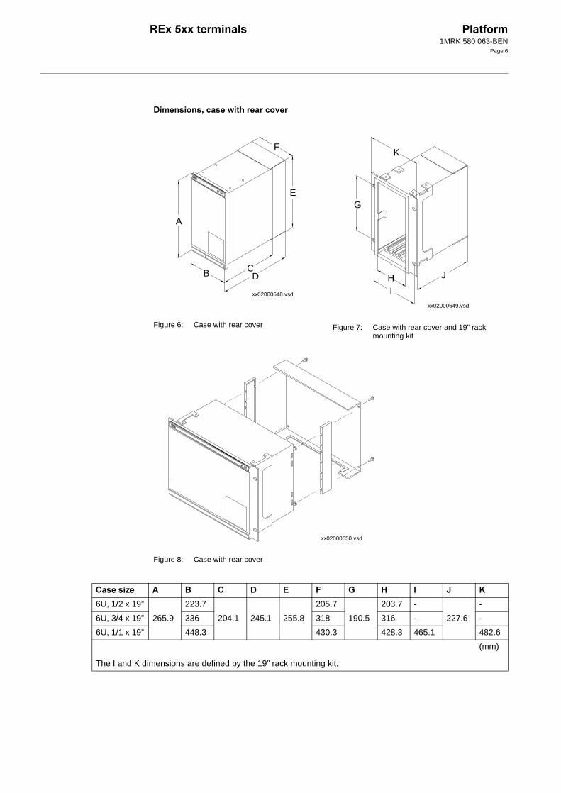
! "& '
Figure 6: Case with rear cover Figure 7: Case with rear cover and 19” rack mounting kit
Figure 8: Case with rear cover
A
B CD
E
F
xx02000648.vsd
J
IH
G
K
xx02000649.vsd
xx02000650.vsd
( ) ( * - + ,
6U, 1/2 x 19” 223.7 205.7 203.7 - -
6U, 3/4 x 19” 265.9 336 204.1 245.1 255.8 318 190.5 316 - 227.6 -
6U, 1/1 x 19” 448.3 430.3 428.3 465.1 482.6
The I and K dimensions are defined by the 19” rack mounting kit.
(mm)

1MRK 580 063-BEN
Page 7
.// !
Flush mounting Semi-flush mounting
A
B
C
D
E
xx02000665.vsd
F
G
xx02000666.vsd
( )
(. 01
23. 23.
6U, 1/2 x 19” 210.1 254.3
6U, 3/4 x 19” 322.4 254.3
6U, 1/1 x 19” 434.7 254.3
C = 4-10 mm
D = 16.5 mm
E = 187.6 mm without rear protection cover, 228.6 mm with rear protection cover
F = 106.5 mm
G = 97.6 mm without rear protection cover, 138.6 mm with rear protection cover

1MRK 580 063-BEN
Page 8
.// ! #
Figure 9: Flush mounting of side by side cases
B
A
C
G
D
E
F
xx02000651.vsd
xx02000652.vsd
( ) (.
(
6U, 3/4 x 19” 326.4 259.3 352.8 190.5 34.4 13.2 ø 6.4
6U, 1/1 x 19” 438.7 259.3 465.1 190.5 34.4 13.2 ø 6.4
(mm)

1MRK 580 063-BEN
Page 9
!"
Figure 10: Wall mounting
80
xx02000653.vsd
E
A
B
CD
Screws M6 orcorresponding
en02000654.vsd
( ) 01 (
6U, 1/2 x 19” 292 267.1
6U, 3/4 x 19” 404.3 379.4 272.8 390 247
6U, 1/1 x 19” 516 491.1

1MRK 580 063-BEN
Page 10
44Use the terminals built-in communication functionality to establish SMS communica-tion with a PC with suitable software tool. Connect the PC to the optical connector on the local HMI with the special front commu-nication cable including an opto-electrical converter for disturbance free and safe com-munication.
Use the terminal identifiers to name the indi-vidual terminal for identification purposes. Use the terminal reports to check serial num-bers of the terminal and installed modules and to check the firmware version.
Identifiers and reports are accessible by using the HMI as well as by SMS or SCS systems.
Use the basic protection parameters to define:
• Main protection transformer ratio.
• Rated values of the transformer module in use.
• Base values for per-unit system.
#&Use the time synchronization source selector to select a common source of absolute time for the terminal when it is a part of a protec-tion system. This makes comparison of events and disturbance data between all ter-minals in a system possible.
4 Use the four sets of settings to optimize the terminals operation for different system con-ditions. By creating and switching between fine tuned setting sets, either from the human-machine interface or configurable binary inputs, results in a highly adaptable terminal that can cope with a variety of system scenar-ios.
4 5Unpermitted or uncoordinated changes by unauthorized personnel may cause severe damage to primary and secondary power cir-cuits. Use the setting lockout function to pre-vent unauthorized setting changes and to control when setting changes are allowed.
By adding a key switch connected to a binary input a simple setting change control circuit can be built simply allowing only authorized keyholders to make setting changes from the built-in HMI.
-36# The I/O system configurator must be used in order for the terminal’s software to recognize added modules and to create internal address mappings between modules and protections and other functions.
%5The user can with the available logic function blocks build logic functions and configure the terminal to meet application specific require-ments.
Different protection, control, and monitoring functions within the REx 5xx terminals are quite independent as far as their configuration in the terminal is concerned. The user can not change the basic algorithms for different functions. But these functions combined with the logic function blocks can be used to cre-ate application specific functionality.
4 '"& ' Use the local HMI, SMS or SCS to view the status of the self-supervision function. The self-supervision operates continuously and includes:
• Normal micro-processor watchdog func-tion
• Checking of digitized measuring signals
• Checksum verification of PROM contents and all types of signal communication
Internal events are generated by the built-in supervisory functions. Events are related to the terminal’s hardware, the operation of the internal calendar and clock, time sychroniza-tion and other status changes.
Retrieve a time tagged list of the last 40 inter-nal events from the SCS or SMS system, when an internal event has occured.
1MRK 580 063-BEN
Page 11
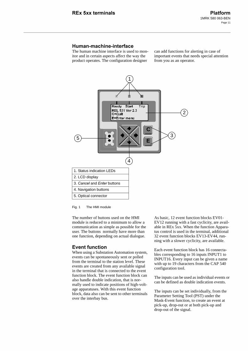
*.& . The human machine interface is used to mon-itor and in certain aspects affect the way the product operates. The configuration designer
can add functions for alerting in case of important events that needs special attention from you as an operator.
Fig. 1 The HMI module
The number of buttons used on the HMI module is reduced to a minimum to allow a communication as simple as possible for the user. The buttons normally have more than one function, depending on actual dialogue.
' When using a Substation Automation system, events can be spontaneously sent or polled from the terminal to the station level. These events are created from any available signal in the terminal that is connected to the event function block. The event function block can also handle double indication, that is nor-mally used to indicate positions of high-volt-age apparatuses. With this event function block, data also can be sent to other terminals over the interbay bus.
As basic, 12 event function blocks EV01-EV12 running with a fast cyclicity, are avail-able in REx 5xx. When the function Appara-tus control is used in the terminal, additional 32 event function blocks EV13-EV44, run-ning with a slower cyclicity, are available.
Each event function block has 16 connecta-bles corresponding to 16 inputs INPUT1 to INPUT16. Every input can be given a name with up to 19 characters from the CAP 540 configuration tool.
The inputs can be used as individual events or can be defined as double indication events.
The inputs can be set individually, from the Parameter Setting Tool (PST) under the Mask-Event function, to create an event at pick-up, drop-out or at both pick-up and drop-out of the signal.
E
C
2
3
1
5
4
1. Status indication LEDs
2. LCD display
3. and buttons
4. Navigation buttons
5. Optical connector
1MRK 580 063-BEN
Page 12
The event function blocks EV01-EV06 have inputs for information numbers and function type, which are used to define the events according to the communication standard IEC 60870-5-103.
5 The protection and control terminals have a complex configuration with many included functions. To make the testing procedure eas-ier, the terminals include the feature to indi-vidually block a single, several or all functions.
This means that it is possible to see when a function is activated or trips. It also enables the user to follow the operation of several related functions to check correct functional-ity and to check parts of the configuration etc.
( 75The internal clock is used for time-tagging disturbances, events in SMS and SCS, and internal events. It handles date, hour, minute, second and millisecond with a resolution of 1 ms. Synchronise the clock by means of a minute pulse through a binary input or via the station bus communication.
The built-in calendar for 30 years handles leap years. Any change between summer and winter time must be handled manually or through external time synchronisation. The clock can handle interruptions in power sup-ply without malfunction.
(
Use the AC monitoring function to provide three phase or single phase values of voltage and current. At three phase measurement, the
values of apparent power, active power, reac-tive power, frequency and the RMS voltage and current for each phase are calculated. Also the average values of currents and volt-ages are calculated.
#Alarm limits can be set and used as triggers, e.g. to generate trip signals.
The software functions to support presenta-tion of measured values are always present in the terminal. In order to retrieve actual val-ues, however, the terminal must be equipped with the appropriate hardware measuring module(s), i.e. Transformer Input Module (TRM) or Optical Receiver Module (ORM).
(
Use the DC monitoring function to measure and process signals from different measuring transducers. Many devices used in process control uses low currents, usually in the range 4-20 mA or 0-20 mA to represent various parameters such as frequency, temperature and DC battery voltage.
#Alarm limits can be set and used as triggers, e.g. to generate trip signals.
The software functions to support presenta-tion of measured values are always present in the terminal. In order to retrieve actual val-ues, however, the terminal must be equipped with the mA Input Module (MIM).
1MRK 580 063-BEN
Page 13
5
#&!-
8 -& -0-.15
9 6& -0-.15
4 !
-& (-:6;0..15
< 6& (-:6;0..15
4 5!*-
= -& 4->4-(-6>5
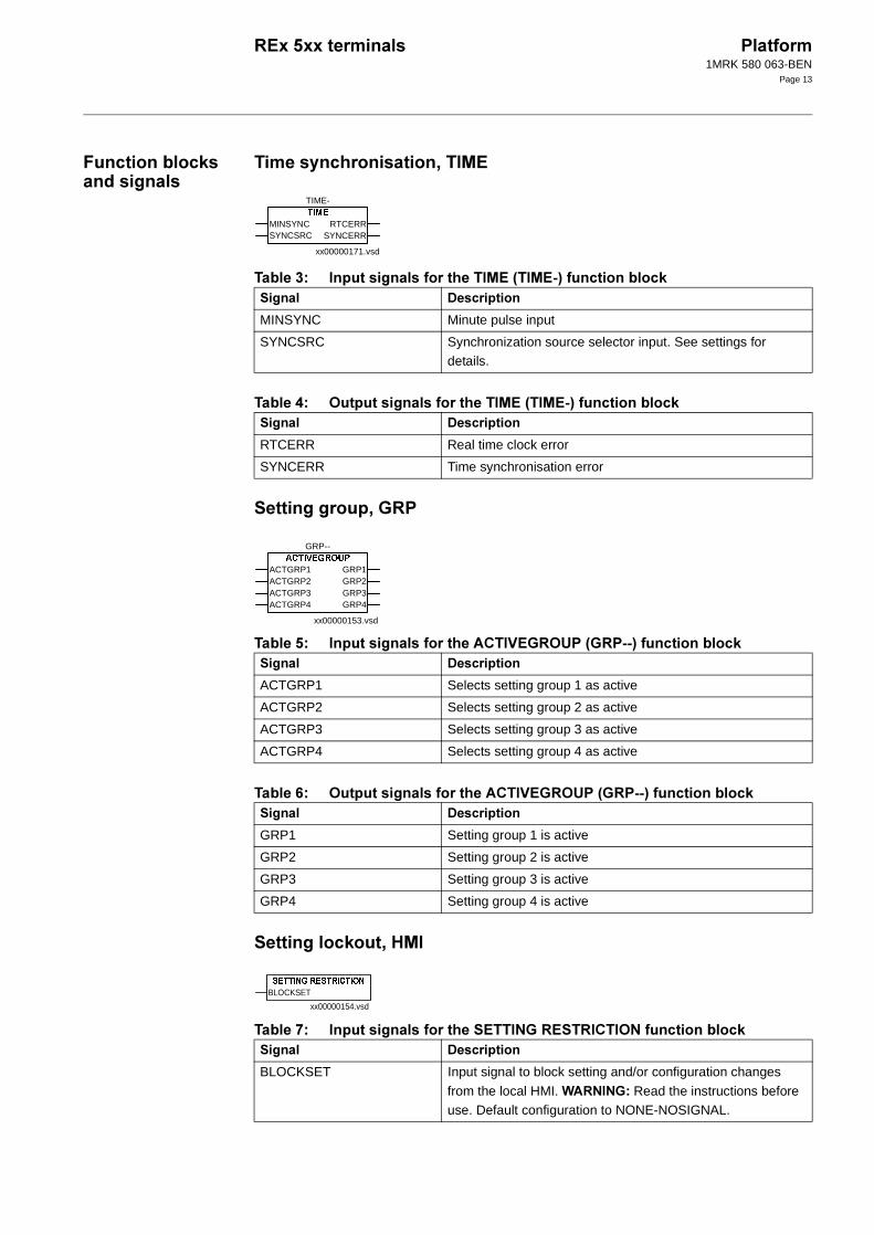
xx00000171.vsd
TIME-
MINSYNCSYNCSRC
RTCERRSYNCERR
4
MINSYNC Minute pulse input
SYNCSRC Synchronization source selector input. See settings for details.
4
RTCERR Real time clock error
SYNCERR Time synchronisation error
xx00000153.vsd
GRP--
ACTGRP1ACTGRP2ACTGRP3ACTGRP4
GRP1GRP2GRP3GRP4
4
ACTGRP1 Selects setting group 1 as active
ACTGRP2 Selects setting group 2 as active
ACTGRP3 Selects setting group 3 as active
ACTGRP4 Selects setting group 4 as active
4
GRP1 Setting group 1 is active
GRP2 Setting group 2 is active
GRP3 Setting group 3 is active
GRP4 Setting group 4 is active
xx00000154.vsd
BLOCKSET
4
BLOCKSET Input signal to block setting and/or configuration changes
from the local HMI. ?>-> Read the instructions before use. Default configuration to NONE-NOSIGNAL.

1MRK 580 063-BEN
Page 14
-36# !-6
@ 6& -3664--6>0-6.15
>!>
A -& >0.15
/ 6& >0.15
xx00000238.vsd
IOP1-
S11S12S13S14S15S16S17S18S19S20S21S22S23S24S25S26S27S28S29S30S32S33S34S35S36S37S39
4
Snn Slot position nn (nn=11-39)
xx00000160.vsd
A001-
INPUT1INPUT2INPUT3INPUT4N
OUTNOUT
4
INPUT1 Input 1 to AND gate
INPUT2 Input 2 to AND gate
INPUT3 Input 3 to AND gate
INPUT4N Input 4 (inverted) to AND gate
4
OUT Output from AND gate
NOUT Inverted output from AND gate

1MRK 580 063-BEN
Page 15
6!6
-& 606.15
$ 6& 606.15
-' !->:
8 -& ->:0-:.15
9 6& ->:0-:.15
xx00000159.vsd
O001-
INPUT1INPUT2INPUT3INPUT4INPUT5INPUT6
OUTNOUT
4
INPUT1 Input 1 to OR gate
INPUT2 Input 2 to OR gate
INPUT3 Input 3 to OR gate
INPUT4 Input 4 to OR gate
INPUT5 Input 5 to OR gate
INPUT6 Input 6 to OR gate
4
OUT Output from OR gate
NOUT Inverted output from OR gate
xx00000158.vsd
IV01-
INPUT OUT
4
INPUT Logic INV-Input to INV gate
4
OUT Logic INV-Output from INV gate

1MRK 580 063-BEN
Page 16
!
-& -0.15
< 6& -0.15
!
= -& 0.15
@ 6& 0.15
4 . "& #!4
A -& 404.15
$/ 6& 404.15
xx00000161.vsd
TM01-
INPUTT
OFFON
4
INPUT Input to timer
T Time value. See setting parameters
4
OFF Output from timer, drop-out delayed
ON Output from timer , pick-up delayed
xx00000163.vsd
TP01-
INPUTT
OUT
4
INPUT Input to pulse timer
T Pulse length. See setting parameters
4
OUT Output from pulse timer
xx00000382.vsd
SM01-
SETRESET
OUTNOUT
4
SET Input to SRM flip-flop
RESET Input to SRM flip-flop
4
OUT Output from SRM flip-flop
NOUT Inverted output from SRM flip-flop

1MRK 580 063-BEN
Page 17
( !
$ -& 0.15
$$ 6& 0.15
4 !4
$8 -& 404.15
$9 6& 404.15
!%
$ -& -%6>0%.15
$< 6& -%6>0%.15
xx00000380.vsd
GT01-
INPUT OUT
4
INPUT Input to gate
4
Out Output from gate
xx00000381.vsd
TS01-
INPUT ONOFF
4
INPUT Input to timer
4
ON Output from timer, pick-up delayed
OFF Output from timer, drop-out delayed
xx00000162.vsd
TL01-
INPUTT
OFFON
4
INPUT Input to long timer
T Time value. See setting parameters
4
OFF Output from long timer, drop-out delayed
ON Output from long timer, pick-up delayed
1MRK 580 063-BEN
Page 18
& !B
$= -& ;%4%6>0B.15
$@ 6& ;%4%6>0B.15
4 . !4
$A -& 404.15
8/ 6& 404.15
' 6!C6
8 -& C60C6.15
8$ 6& C60C6.15
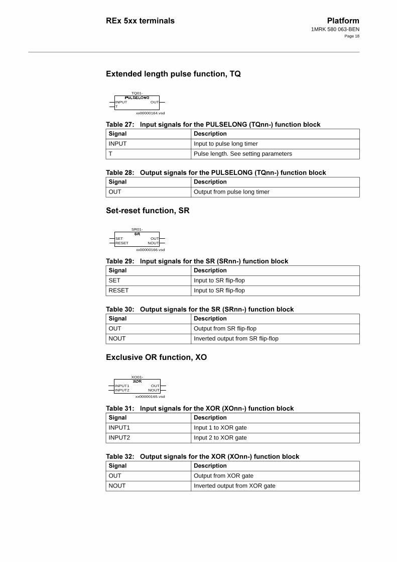
xx00000164.vsd
TQ01-
INPUTT
OUT
4
INPUT Input to pulse long timer
T Pulse length. See setting parameters
4
OUT Output from pulse long timer
xx00000166.vsd
SR01-
SETRESET
OUTNOUT
4
SET Input to SR flip-flop
RESET Input to SR flip-flop
4
OUT Output from SR flip-flop
NOUT Inverted output from SR flip-flop
xx00000165.vsd
XO01-
INPUT1INPUT2
OUTNOUT
4
INPUT1 Input 1 to XOR gate
INPUT2 Input 2 to XOR gate
4
OUT Output from XOR gate
NOUT Inverted output from XOR gate
1MRK 580 063-BEN
Page 19
4 '!->
88 6& ->>4->%40->..15
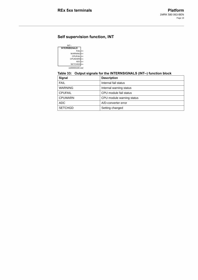
xx00000169.vsd
INT--
FAILWARNING
CPUFAILCPUWARN
ADCSETCHGD
4
FAIL Internal fail status
WARNING Internal warning status
CPUFAIL CPU module fail status
CPUWARN CPU module warning status
ADC A/D-converter error
SETCHGD Setting changed
1MRK 580 063-BEN
Page 20
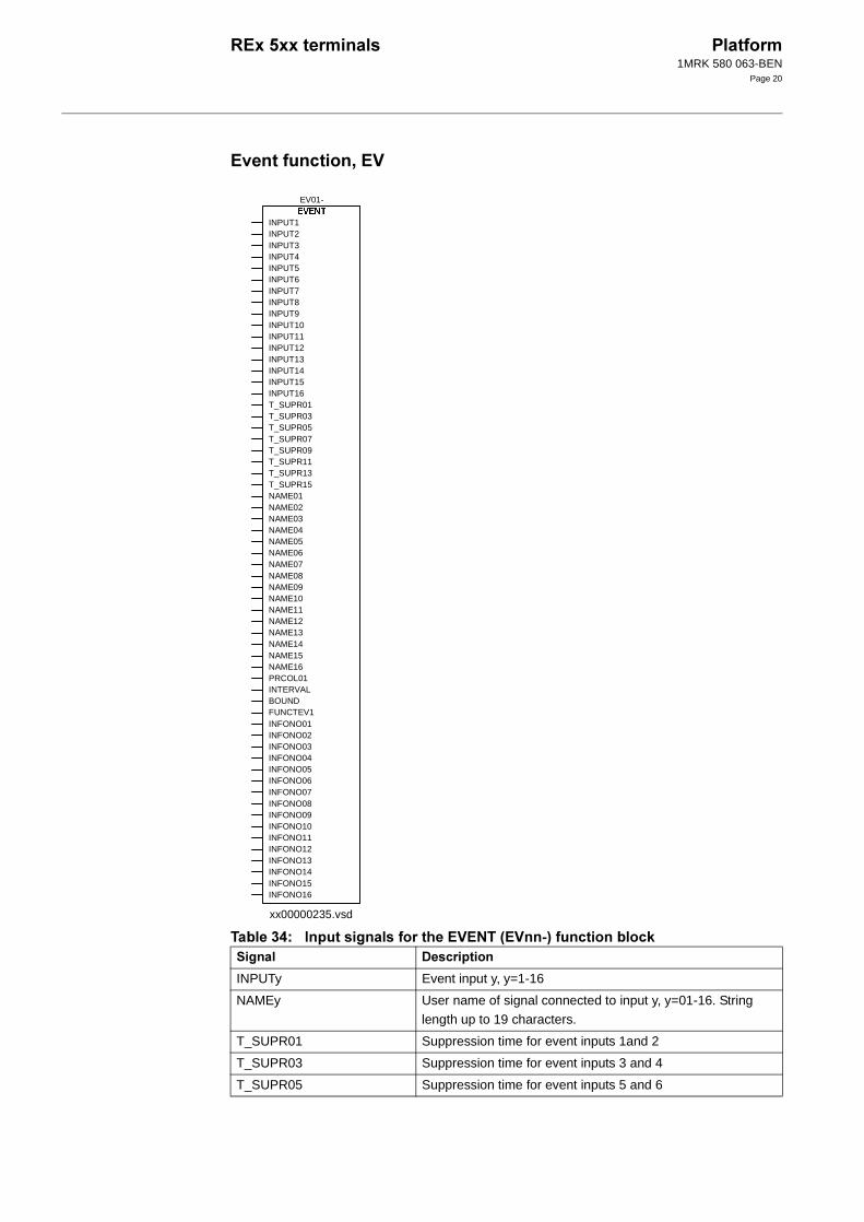
' !:
89 -& :>0:.15
xx00000235.vsd
EV01-
INPUT1INPUT2INPUT3INPUT4INPUT5INPUT6INPUT7INPUT8INPUT9INPUT10INPUT11INPUT12INPUT13INPUT14INPUT15INPUT16T_SUPR01T_SUPR03T_SUPR05T_SUPR07T_SUPR09T_SUPR11T_SUPR13T_SUPR15NAME01NAME02NAME03NAME04NAME05NAME06NAME07NAME08NAME09NAME10NAME11NAME12NAME13NAME14NAME15NAME16PRCOL01INTERVALBOUNDFUNCTEV1INFONO01INFONO02INFONO03INFONO04INFONO05INFONO06INFONO07INFONO08INFONO09INFONO10INFONO11INFONO12INFONO13INFONO14INFONO15INFONO16
4
INPUTy Event input y, y=1-16
NAMEy User name of signal connected to input y, y=01-16. String
length up to 19 characters.
T_SUPR01 Suppression time for event inputs 1and 2
T_SUPR03 Suppression time for event inputs 3 and 4
T_SUPR05 Suppression time for event inputs 5 and 6
1MRK 580 063-BEN
Page 21
5 !4
8 -& 04.15
8< 6& 04.15
" # !4
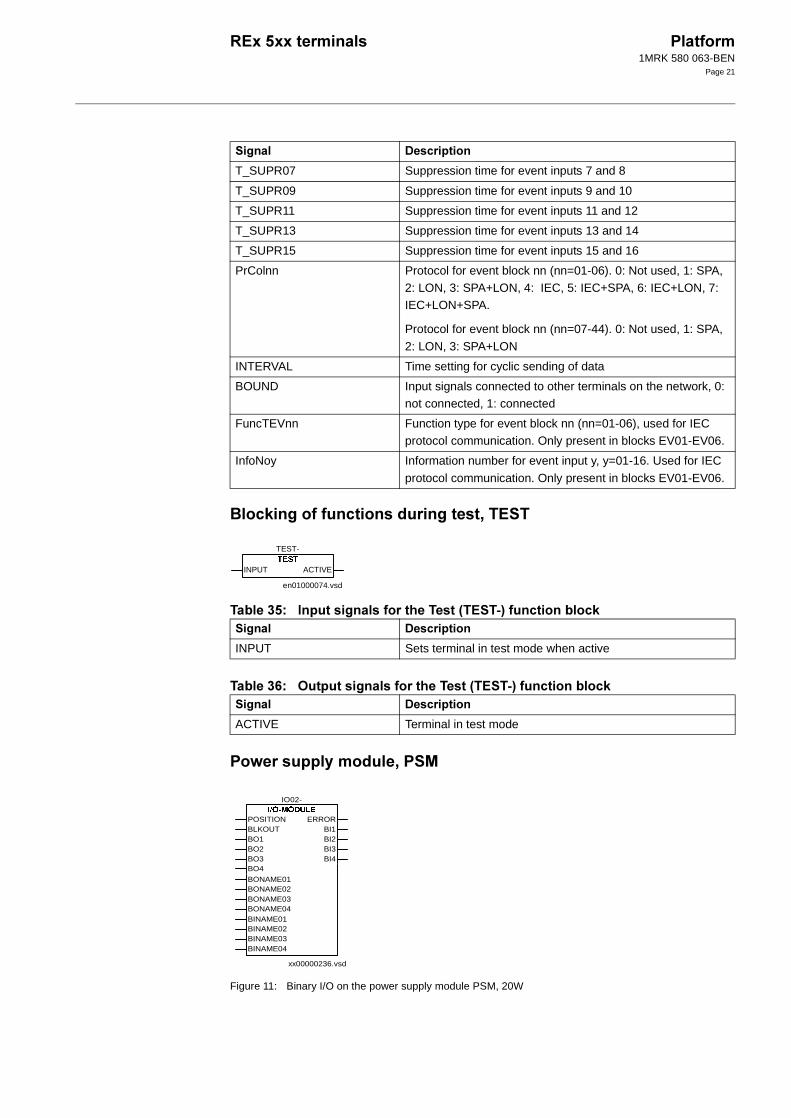
Figure 11: Binary I/O on the power supply module PSM, 20W
T_SUPR07 Suppression time for event inputs 7 and 8
T_SUPR09 Suppression time for event inputs 9 and 10
T_SUPR11 Suppression time for event inputs 11 and 12
T_SUPR13 Suppression time for event inputs 13 and 14
T_SUPR15 Suppression time for event inputs 15 and 16
PrColnn Protocol for event block nn (nn=01-06). 0: Not used, 1: SPA, 2: LON, 3: SPA+LON, 4: IEC, 5: IEC+SPA, 6: IEC+LON, 7: IEC+LON+SPA.
Protocol for event block nn (nn=07-44). 0: Not used, 1: SPA,
2: LON, 3: SPA+LON
INTERVAL Time setting for cyclic sending of data
BOUND Input signals connected to other terminals on the network, 0: not connected, 1: connected
FuncTEVnn Function type for event block nn (nn=01-06), used for IEC protocol communication. Only present in blocks EV01-EV06.
InfoNoy Information number for event input y, y=01-16. Used for IEC
protocol communication. Only present in blocks EV01-EV06.
4
TEST-
INPUT ACTIVE
en01000074.vsd
4
INPUT Sets terminal in test mode when active
4
ACTIVE Terminal in test mode
IO02-
POSITIONBLKOUTBO1BO2BO3BO4BONAME01BONAME02BONAME03BONAME04BINAME01BINAME02BINAME03BINAME04
ERRORBI1BI2BI3BI4
xx00000236.vsd

1MRK 580 063-BEN
Page 22
8= -& -36. 0-6/$.150-3641!$/?
8@ 6& -36. 0-6/$.150-3641!$/?
( !-
Figure 12: A MIM module (mA input module) has six input channels. Each channel has a function block, MIxn-, where x=(1-6) is the number of the MIM module, and n=(1-6) is the number of the chan-nel.
8A -& -0-.15
9/ 6& -0-.15
4
POSITION I/O module slot position connector
BLKOUT Block output signals
BO01-BO04 Binary output data
BONAME01-BONAME04 Output name string settings
BINAME01-BINAME04 Input name string settings
4
ERROR I/O-module fail
BI1-BI4 Binary input data
xx00000232.vsd
MIxn-
POSITIONBLOCK
ERRORINPUTERR
RMAXALRMINAL
HIALARMHIWARN
LOWWARNLOWALARM
4
POSITION I/O module slot position connector. Only present in first instance of block for each present input module.
BLOCK Block value updating
4
ERROR Module fail. Only present in first instance of block for each
present input module.
INPUTERR Input error
RMAXAL Upper range limit reached
HIALARM Input high alarm limit reached
HIWARN Input high warning limit reached
LOWWARN Input low warning limit reached
LOWALARM Input low alarm limit reached
RMINAL Lower range limit reached
1MRK 580 063-BEN
Page 23
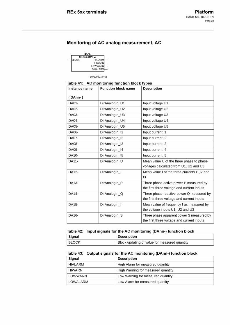
( !(
9 (5#
9$ -& (0.15
98 6& (0.15
BLOCK HIALARMHIWARN
LOWWARNLOWALARM
en01000073.vsd
DA01- DirAnalogIn_U1 Input voltage U1
DA02- DirAnalogIn_U2 Input voltage U2
DA03- DirAnalogIn_U3 Input voltage U3
DA04- DirAnalogIn_U4 Input voltage U4
DA05- DirAnalogIn_U5 Input voltage U5
DA06- DirAnalogIn_I1 Input current I1
DA07- DirAnalogIn_I2 Input current I2
DA08- DirAnalogIn_I3 Input current I3
DA09- DirAnalogIn_I4 Input current I4
DA10- DirAnalogIn_I5 Input current I5
DA11- DirAnalogIn_U Mean value U of the three phase to phase voltages calculated from U1, U2 and U3
DA12- DirAnalogIn_I Mean value I of the three currents I1,I2 and
I3
DA13- DirAnalogIn_P Three phase active power P measured by the first three voltage and current inputs
DA14- DirAnalogIn_Q Three phase reactive power Q measured by the first three voltage and current inputs
DA15- DirAnalogIn_f Mean value of frequency f as measured by
the voltage inputs U1, U2 and U3
DA16- DirAnalogIn_S Three phase apparent power S measured by the first three voltage and current inputs
BLOCK Block updating of value for measured quantity
HIALARM High Alarm for measured quantity
HIWARN High Warning for measured quantity
LOWWARN Low Warning for measured quantity
LOWALARM Low Alarm for measured quantity
1MRK 580 063-BEN
Page 24
!" ##$ %
#$ &!
#'$ ()*+,*&
#-$ (./0."1"
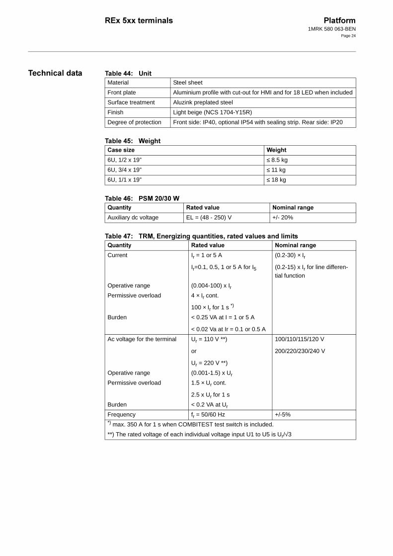
Material Steel sheet
Front plate Aluminium profile with cut-out for HMI and for 18 LED when included
Surface treatment Aluzink preplated steel
Finish Light beige (NCS 1704-Y15R)
Degree of protection Front side: IP40, optional IP54 with sealing strip. Rear side: IP20
2/ &!
6U, 1/2 x 19” ≤ 8.5 kg
6U, 3/4 x 19” ≤ 11 kg
6U, 1/1 x 19” ≤ 18 kg
34 "1 5
Auxiliary dc voltage EL = (48 - 250) V +/- 20%
34 "1 5
Current Ir = 1 or 5 A
Ir=0.1, 0.5, 1 or 5 A for I5
(0.2-30) × Ir
(0.2-15) x Ir for line differen-tial function
Operative range (0.004-100) x IrPermissive overload 4 × Ir cont.
100 × Ir for 1 s *)
Burden < 0.25 VA at I = 1 or 5 A
< 0.02 Va at Ir = 0.1 or 0.5 A
Ac voltage for the terminal Ur = 110 V **)
or
Ur = 220 V **)
100/110/115/120 V
200/220/230/240 V
Operative range (0.001-1.5) x Ur
Permissive overload 1.5 × Ur cont.
2.5 x Ur for 1 s
Burden < 0.2 VA at Ur
Frequency fr = 50/60 Hz +/-5%*) max. 350 A for 1 s when COMBITEST test switch is included.
**) The rated voltage of each individual voltage input U1 to U5 is Ur/√3

1MRK 580 063-BEN
Page 25
#6$ "!"4
#7$ 42414"
*$ 4
8$
)$ 2
,$ (!
1 5
Ambient temperature
Operative range
+20 °C
-25 °C to +55°C
-5 °C to +55 °C 0.01%/°C
Relative humidity
Operative range
10%-90%
0%-95%
10%-90% -
Storage temperature -40 °C to +70 °C - -
"$ &!
Ripple, in DC auxiliary voltage Max 12%
Interrupted auxiliary DC voltage
Without reset <50 ms
Correct function 0-∞ s
Restart time <120 s
41 ""
1 MHz burst disturbance 2.5 kV IEC 60255-22-1, Class III
Electrostatic discharge 8 kV IEC 60255-22-2, Class III
Fast transient disturbance 4 kV IEC 60255-22-4, Class IV
Radiated electromagnetic field distur-bance
10 V/m, 25-1000 MHz
IEC 60255-22-3, Class III IEEE/ANSI C37.90.2
41 ""
Dielectric test 2.0 kVAC, 1 min. IEC 60255-5
Impulse voltage test 5 kV, 1.2/50 µs, 0.5 J
Insulation resistance >100 MΩ at 500 VDC
"
Immunity EN 50082-2
Emissivity EN 50081-2
Low voltage directive EN 50178
41 ""
Vibration Class I IEC 60255-21-1
Shock and bump Class I IEC 60255-21-2
Seismic Class I IEC 60255-21-3
1MRK 580 063-BEN
Page 26
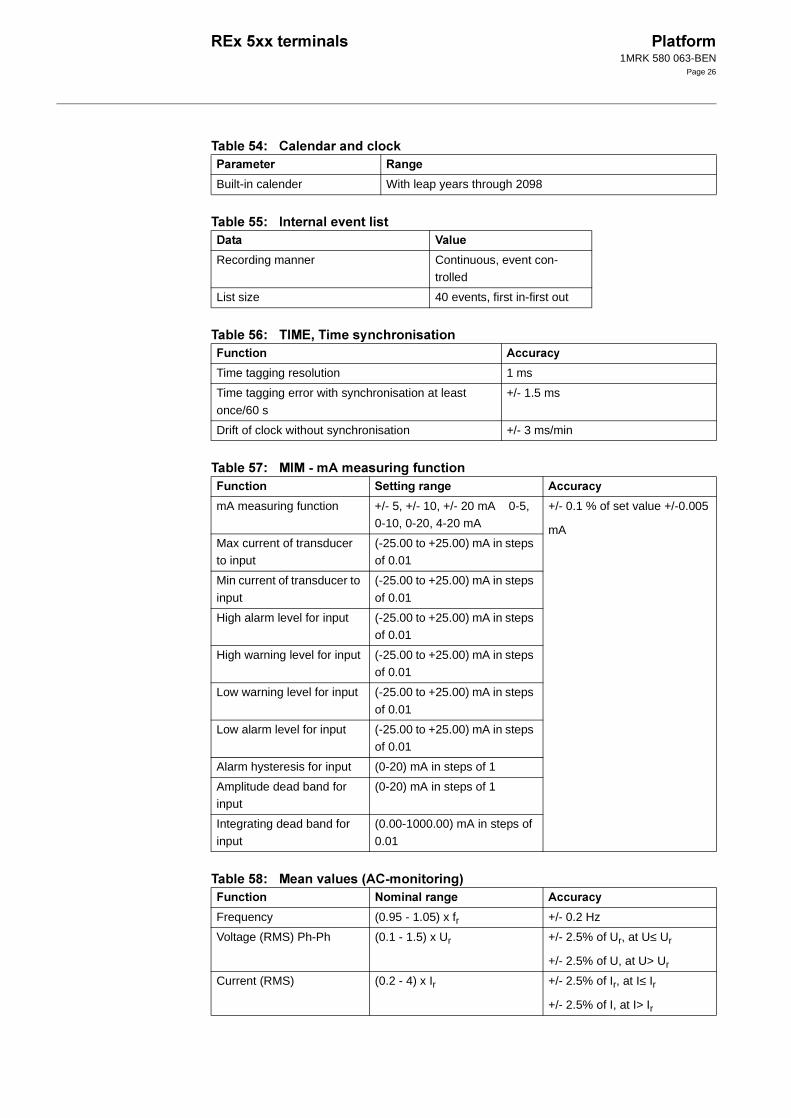
#$ 2""
$ 1
'$ (. 4!
-$ ((
6$ (12
Built-in calender With leap years through 2098
9
Recording manner Continuous, event con-trolled
List size 40 events, first in-first out
4
Time tagging resolution 1 ms
Time tagging error with synchronisation at least
once/60 s
+/- 1.5 ms
Drift of clock without synchronisation +/- 3 ms/min
4
mA measuring function +/- 5, +/- 10, +/- 20 mA 0-5, 0-10, 0-20, 4-20 mA
+/- 0.1 % of set value +/-0.005
mAMax current of transducer to input
(-25.00 to +25.00) mA in steps of 0.01
Min current of transducer to
input
(-25.00 to +25.00) mA in steps
of 0.01
High alarm level for input (-25.00 to +25.00) mA in steps of 0.01
High warning level for input (-25.00 to +25.00) mA in steps of 0.01
Low warning level for input (-25.00 to +25.00) mA in steps
of 0.01
Low alarm level for input (-25.00 to +25.00) mA in steps of 0.01
Alarm hysteresis for input (0-20) mA in steps of 1
Amplitude dead band for input
(0-20) mA in steps of 1
Integrating dead band for
input
(0.00-1000.00) mA in steps of
0.01
5 4
Frequency (0.95 - 1.05) x fr +/- 0.2 Hz
Voltage (RMS) Ph-Ph (0.1 - 1.5) x Ur +/- 2.5% of Ur, at U≤ Ur
+/- 2.5% of U, at U> Ur
Current (RMS) (0.2 - 4) x Ir +/- 2.5% of Ir, at I≤ Ir
+/- 2.5% of I, at I> Ir

1MRK 580 063-BEN
Page 27
7$ (1:!"42
'*$ 1
'8$ (1
Active power*) at |cos ϕ| ≥ 0.9 +/- 5%
Reactive power*) at |cos ϕ| ≤ 0.8 +/- 7.5%
*) Measured at Ur and 20% of Ir
5 4
Frequency (0.95 - 1.05) x fr +/- 0.2 Hz
Voltage (RMS) Ph-Ph (0.8 - 1.2) x Ur +/- 0.25% of Ur, at U<= Ur
+/- 0.25% of U, at U> Ur
Current (RMS) (0.2 - 2) x Ir +/- 0.25% of Ir, at I<= Ir
+/- 0.25% of I, at I> IrActive power 0.8 x Ur < U < 1.2 x Ur
0.2 x Ir < I < 2 x Ir
Active power, |cosϕ|>= 0.9
+/- 0.5% of Pr at P <= Pr *),
+/- 0.5% of P at P > Pr *),
*) Pr: Active power at U = Ur , I = Ir and |cosϕ|= 1
%" ; 14
6 ms AND 30 gates
OR 60 gates
INV 20 inverters
TM 10 timers
TP 10 pulse timers
SM 5 flip-flops
GT 5 gates
TS 5 timers
200 ms TL 10 timers
TQ 10 pulse timers
SR 5 flip-flops
XOR 39 gates
9
Protocol SPA
Communication speed for the terminals 300, 1200, 2400, 4800, 9600 Kbaud
Slave number 1 to 899
Change of active group allowed Yes
Change of settings allowed Yes
5 4
1MRK 580 063-BEN
Page 28
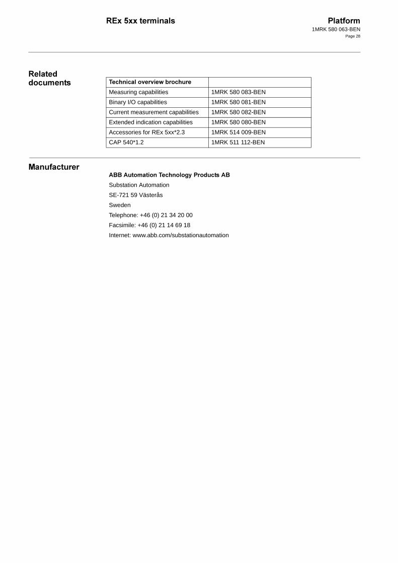
""
(
!11:!
Measuring capabilities 1MRK 580 083-BEN
Binary I/O capabilities 1MRK 580 081-BEN
Current measurement capabilities 1MRK 580 082-BEN
Extended indication capabilities 1MRK 580 080-BEN
Accessories for REx 5xx*2.3 1MRK 514 009-BEN
CAP 540*1.2 1MRK 511 112-BEN
;; !4";
Substation Automation
SE-721 59 Västerås
Sweden
Telephone: +46 (0) 21 34 20 00
Facsimile: +46 (0) 21 14 69 18
Internet: www.abb.com/substationautomation