platform management fru information storage definition v1 ... fileotherwise arising out of any...
TRANSCRIPT
- IPMI -
Platform Management FRU Information Storage Definition
v1.0
Document Revision 1.2
February 28, 2013
Intel Hewlett-Packard NEC Dell
Platform Management FRU Information Storage Definition
ii
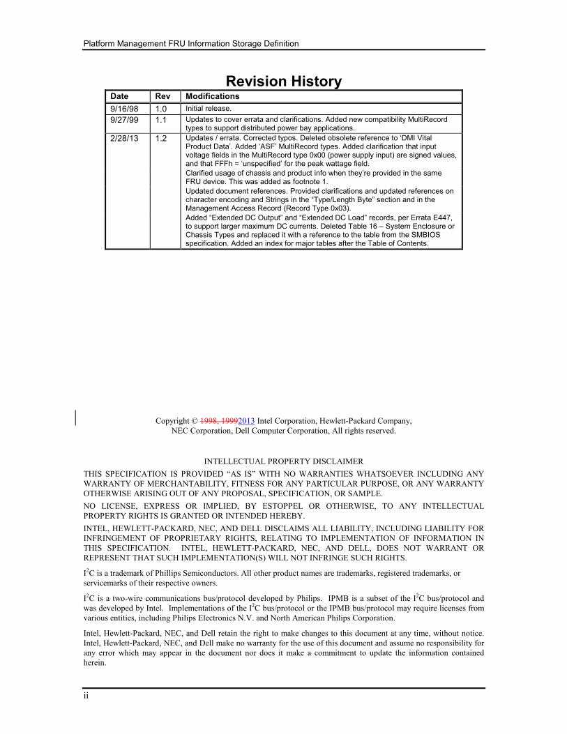
Revision History Date Rev Modifications
9/16/98 1.0 Initial release.
9/27/99 1.1 Updates to cover errata and clarifications. Added new compatibility MultiRecord types to support distributed power bay applications.
2/28/13 1.2 Updates / errata. Corrected typos. Deleted obsolete reference to ‘DMI Vital Product Data’. Added ‘ASF’ MultiRecord types. Added clarification that input voltage fields in the MultiRecord type 0x00 (power supply input) are signed values, and that FFFh = ‘unspecified’ for the peak wattage field.
Clarified usage of chassis and product info when they’re provided in the same FRU device. This was added as footnote 1.
Updated document references. Provided clarifications and updated references on character encoding and Strings in the “Type/Length Byte” section and in the Management Access Record (Record Type 0x03).
Added “Extended DC Output” and “Extended DC Load” records, per Errata E447, to support larger maximum DC currents. Deleted Table 16 – System Enclosure or Chassis Types and replaced it with a reference to the table from the SMBIOS specification. Added an index for major tables after the Table of Contents.
Copyright © 1998, 19992013 Intel Corporation, Hewlett-Packard Company,
NEC Corporation, Dell Computer Corporation, All rights reserved.
INTELLECTUAL PROPERTY DISCLAIMER
THIS SPECIFICATION IS PROVIDED “AS IS” WITH NO WARRANTIES WHATSOEVER INCLUDING ANY
WARRANTY OF MERCHANTABILITY, FITNESS FOR ANY PARTICULAR PURPOSE, OR ANY WARRANTY
OTHERWISE ARISING OUT OF ANY PROPOSAL, SPECIFICATION, OR SAMPLE.
NO LICENSE, EXPRESS OR IMPLIED, BY ESTOPPEL OR OTHERWISE, TO ANY INTELLECTUAL
PROPERTY RIGHTS IS GRANTED OR INTENDED HEREBY.
INTEL, HEWLETT-PACKARD, NEC, AND DELL DISCLAIMS ALL LIABILITY, INCLUDING LIABILITY FOR
INFRINGEMENT OF PROPRIETARY RIGHTS, RELATING TO IMPLEMENTATION OF INFORMATION IN
THIS SPECIFICATION. INTEL, HEWLETT-PACKARD, NEC, AND DELL, DOES NOT WARRANT OR
REPRESENT THAT SUCH IMPLEMENTATION(S) WILL NOT INFRINGE SUCH RIGHTS.
I2C is a trademark of Phillips Semiconductors. All other product names are trademarks, registered trademarks, or
servicemarks of their respective owners.
I2C is a two-wire communications bus/protocol developed by Philips. IPMB is a subset of the I2C bus/protocol and
was developed by Intel. Implementations of the I2C bus/protocol or the IPMB bus/protocol may require licenses from
various entities, including Philips Electronics N.V. and North American Philips Corporation.
Intel, Hewlett-Packard, NEC, and Dell retain the right to make changes to this document at any time, without notice.
Intel, Hewlett-Packard, NEC, and Dell make no warranty for the use of this document and assume no responsibility for
any error which may appear in the document nor does it make a commitment to update the information contained
herein.
Platform Management FRU Information Storage Definition
iii
Table of Contents
1. Introduction ................................................................................................... 1
2. Reference Documents .................................................................................. 2
3. Accessing FRU Inventory Devices .............................................................. 2
4. Accessing FRU Inventory Device Data ....................................................... 3
5. More on Predefined and Custom Fields ..................................................... 3
6. Suggested Storage Organization ................................................................ 5
7. Changing Area Allocations .......................................................................... 5
8. Common Header Format .............................................................................. 6
9. Internal Use Area Format ............................................................................. 6
10. Chassis Info Area Format............................................................................. 7
11. Board Info Area Format ................................................................................ 8
12. Product Info Area Format ............................................................................. 9
13. TYPE/LENGTH BYTE FORMAT .................................................................. 10
13.1 BCD PLUS definition: ................................................................................................... 10
13.2 6-bit ASCII definition .................................................................................................... 11
13.3 6-bit ASCII Packing Example ........................................................................................ 11
14. System Enclosure and Chassis Types ..................................................... 12
15. Language Codes ......................................................................................... 13
16. MultiRecord Area ........................................................................................ 14
16.1 Record Header ............................................................................................................... 14
16.2 Record Header Fields ..................................................................................................... 14
16.2.1 Record Type Identification ....................................................................................... 14
16.2.2 End of List ................................................................................................................ 15
16.2.3 Record Format Version ............................................................................................ 15
16.2.4 Record Length .......................................................................................................... 15
16.2.5 Record Checksum ..................................................................................................... 15
16.2.6 Header Checksum ..................................................................................................... 15
17. FRU Information Layout ............................................................................. 16
18. Record Field Definitions ............................................................................. 17
18.1 Power Supply Information (Record Type 0x00) ............................................................ 17
Platform Management FRU Information Storage Definition
iv
18.1.1 Overall Capacity in Watts ........................................................................................ 17
18.1.2 Peak VA .................................................................................................................... 18
18.1.3 Inrush ........................................................................................................................ 18
18.1.4 Inrush interval ........................................................................................................... 18
18.1.5 Low end Input voltage range 1 ................................................................................. 18
18.1.6 High end Input voltage range 1 ................................................................................ 18
18.1.7 Low end Input voltage range 2 ................................................................................. 18
18.1.8 High end Input voltage range 2 ................................................................................ 18
18.1.9 Low end input frequency range ................................................................................ 18
18.1.10 High end input frequency range ............................................................................... 18
18.1.11 Input dropout tolerance ............................................................................................. 18
18.1.12 Binary flags............................................................................................................... 18
18.1.13 Peak Wattage ............................................................................................................ 19
18.1.14 Combined Wattage ................................................................................................... 19
18.1.15 Predictive fail tachometer lower threshold ............................................................... 19
18.2 DC Output (Record Type 0x01) .................................................................................... 20
18.2.1 Output Information ................................................................................................... 20
18.2.2 Nominal voltage ....................................................................................................... 21
18.2.3 Maximum negative voltage ...................................................................................... 21
18.2.4 Maximum positive voltage ....................................................................................... 21
18.2.5 Ripple and Noise pk-pk, 10Hz to 30MHz ................................................................ 21
18.2.6 Minimum current draw ............................................................................................. 21
18.2.7 Maximum current draw ............................................................................................ 21
18.2a Extended DC Output (Record Type 0x09) .................................................................... 22
18.3 DC Load (Record Type 0x02) ....................................................................................... 22
18.3.1 Output Information ................................................................................................... 22
18.3.2 Nominal voltage ....................................................................................................... 23
18.3.3 Spec'd minimum voltage ........................................................................................... 23
18.3.4 Spec'd maximum voltage .......................................................................................... 23
18.3.5 Ripple and Noise pk-pk 10Hz to 30MHz ................................................................. 23
18.3.6 Minimum current load .............................................................................................. 23
18.3.7 Maximum current load ............................................................................................. 23
18.3a Extended DC Load (Record Type 0x0A) ...................................................................... 23
18.4 Management Access Record (Record Type 0x03) ........................................................ 24
18.4.1 Example .................................................................................................................... 24
18.5 Base Compatibility Record (Record Type 0x04) ........................................................... 27
18.6 Extended Compatibility Record (Record Type 0x05) ................................................... 28
18.6.1 Code Range Mask Fields Usage Example ................................................................ 29
18.7 OEM Record (Record Types 0xC0-0xFF) ..................................................................... 29
Platform Management FRU Information Storage Definition
v
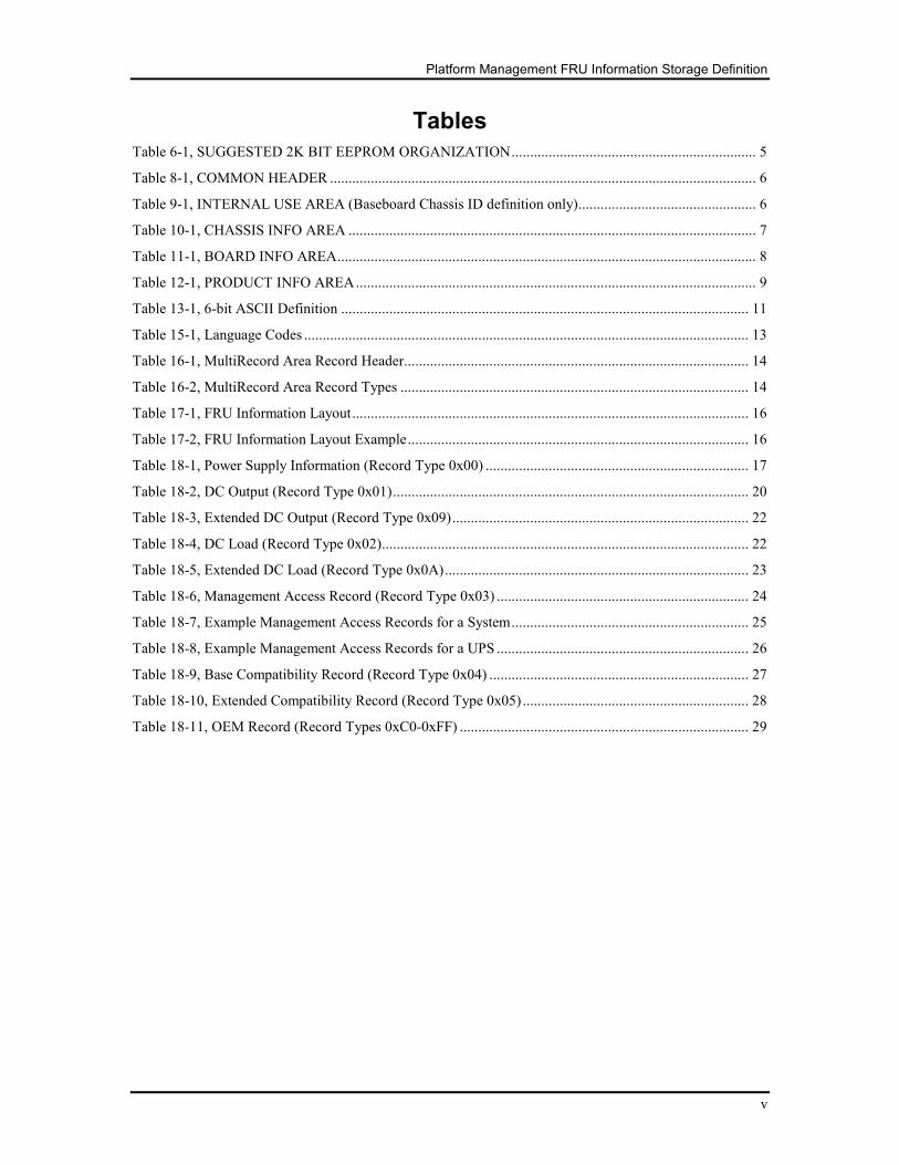
Tables
Table 6-1, SUGGESTED 2K BIT EEPROM ORGANIZATION .................................................................. 5
Table 8-1, COMMON HEADER ................................................................................................................... 6
Table 9-1, INTERNAL USE AREA (Baseboard Chassis ID definition only) ................................................ 6
Table 10-1, CHASSIS INFO AREA .............................................................................................................. 7
Table 11-1, BOARD INFO AREA ................................................................................................................. 8
Table 12-1, PRODUCT INFO AREA ............................................................................................................ 9
Table 13-1, 6-bit ASCII Definition .............................................................................................................. 11
Table 15-1, Language Codes ........................................................................................................................ 13
Table 16-1, MultiRecord Area Record Header ............................................................................................. 14
Table 16-2, MultiRecord Area Record Types .............................................................................................. 14
Table 17-1, FRU Information Layout ........................................................................................................... 16
Table 17-2, FRU Information Layout Example ............................................................................................ 16
Table 18-1, Power Supply Information (Record Type 0x00) ....................................................................... 17
Table 18-2, DC Output (Record Type 0x01) ................................................................................................ 20
Table 18-3, Extended DC Output (Record Type 0x09) ................................................................................ 22
Table 18-4, DC Load (Record Type 0x02) ................................................................................................... 22
Table 18-5, Extended DC Load (Record Type 0x0A) .................................................................................. 23
Table 18-6, Management Access Record (Record Type 0x03) .................................................................... 24
Table 18-7, Example Management Access Records for a System ................................................................ 25
Table 18-8, Example Management Access Records for a UPS .................................................................... 26
Table 18-9, Base Compatibility Record (Record Type 0x04) ...................................................................... 27
Table 18-10, Extended Compatibility Record (Record Type 0x05) ............................................................. 28
Table 18-11, OEM Record (Record Types 0xC0-0xFF) .............................................................................. 29

Platform Management FRU Information Storage Definition
vi
Platform Management FRU Information Storage Definition
1
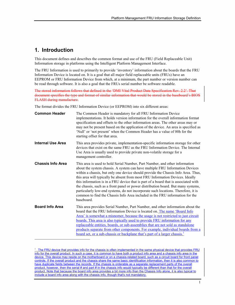
1. Introduction
This document defines and describes the common format and use of the FRU (Field Replaceable Unit)
Information storage in platforms using the Intelligent Platform Management Interface.
The FRU Information is used to primarily to provide ‘inventory’ information about the boards that the FRU
Information Device is located on. It is a goal that all major field replaceable units (FRUs) have an
EEPROM or FRU Information Device from which, at a minimum, the part number or version number can
be read through software. It is also a goal that the FRUs serial number be software readable.
The stored information follows that defined in the ‘DMI Vital Product Data Specification Rev. 2.2’. That
document specifies the type and format of similar information that would be stored in the baseboard’s BIOS
FLASH during manufacture.
The format divides the FRU Information Device (or EEPROM) into six different areas:
Common Header The Common Header is mandatory for all FRU Information Device
implementations. It holds version information for the overall information format
specification and offsets to the other information areas. The other areas may or
may not be present based on the application of the device. An area is specified as
‘Null’ or ‘not present’ when the Common Header has a value of 00h for the
starting offset for that area.
Internal Use Area This area provides private, implementation-specific information storage for other
devices that exist on the same FRU as the FRU Information Device. The Internal
Use Area is usually used to provide private non-volatile storage for a
management controller.
Chassis Info Area This area is used to hold Serial Number, Part Number, and other information
about the system chassis. A system can have multiple FRU Information Devices
within a chassis, but only one device should provide the Chassis Info Area. Thus,
this area will typically be absent from most FRU Information Devices. Ideally
this information is in a FRU device that is part of a board that is associated with
the chassis, such as a front panel or power distribution board. But many systems,
particularly low-end systems, do not incorporate such locations. Therefore, it is
common to find the Chassis Info Area included in the FRU information for the
baseboard.
Board Info Area This area provides Serial Number, Part Number, and other information about the
board that the FRU Information Device is located on. The name ‘Board Info
Area’ is somewhat a misnomer, because the usage is not restricted to just circuit
boards. This area is also typically used to provide FRU information for any
replaceable entities, boards, or sub-assemblies that are not sold as standalone
products separate from other components. For example, individual boards from a
board set, or a sub-chassis or backplane that’s part of a larger chassis.1
1 The FRU device that provides info for the chassis is often implemented in the same physical device that provides FRU info for the overall product. In such a case, it is common to have both a product info area and a chassis info area in the device. This device may reside on the motherboard or on a chassis-related board, such as a circuit board for front panel controls. If the overall product and the chassis share the same basic identification information, then it is also common to have duplicate fields between the records. If the chassis is orderable as a separate replacement parts of the overall product, however, then the serial # and part # in the chassis info would typically be different than that for the overall product. Note that because the board info area provides a bit more info than the Chassis Info alone, it is also typical to include a board info area along with the chassis info, though that's not mandatory.
Platform Management FRU Information Storage Definition
2
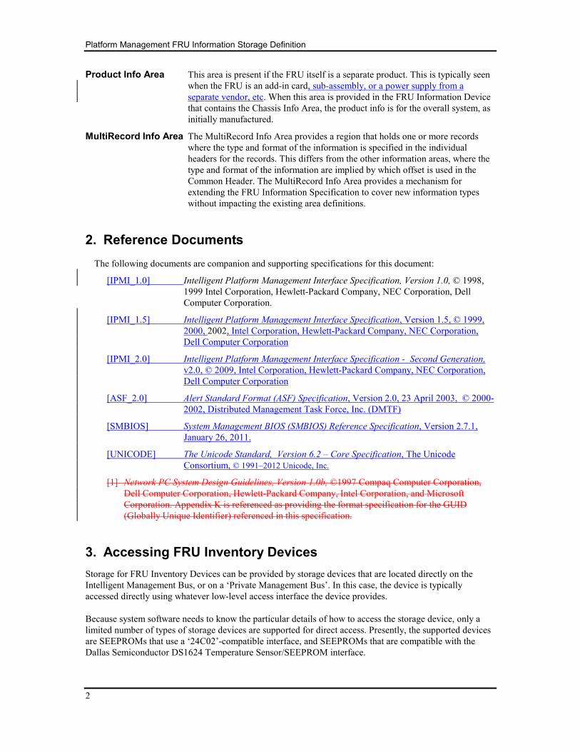
Product Info Area This area is present if the FRU itself is a separate product. This is typically seen
when the FRU is an add-in card, sub-assembly, or a power supply from a
separate vendor, etc. When this area is provided in the FRU Information Device
that contains the Chassis Info Area, the product info is for the overall system, as
initially manufactured.
MultiRecord Info Area The MultiRecord Info Area provides a region that holds one or more records
where the type and format of the information is specified in the individual
headers for the records. This differs from the other information areas, where the
type and format of the information are implied by which offset is used in the
Common Header. The MultiRecord Info Area provides a mechanism for
extending the FRU Information Specification to cover new information types
without impacting the existing area definitions.
2. Reference Documents
The following documents are companion and supporting specifications for this document:
[IPMI_1.0] Intelligent Platform Management Interface Specification, Version 1.0, © 1998,
1999 Intel Corporation, Hewlett-Packard Company, NEC Corporation, Dell
Computer Corporation.
[IPMI_1.5] Intelligent Platform Management Interface Specification, Version 1.5, © 1999,
2000, 2002, Intel Corporation, Hewlett-Packard Company, NEC Corporation,
Dell Computer Corporation
[IPMI_2.0] Intelligent Platform Management Interface Specification - Second Generation,
v2.0, © 2009, Intel Corporation, Hewlett-Packard Company, NEC Corporation,
Dell Computer Corporation
[ASF_2.0] Alert Standard Format (ASF) Specification, Version 2.0, 23 April 2003, © 2000-
2002, Distributed Management Task Force, Inc. (DMTF)
[SMBIOS] System Management BIOS (SMBIOS) Reference Specification, Version 2.7.1,
January 26, 2011.
[UNICODE] The Unicode Standard, Version 6.2 – Core Specification, The Unicode
Consortium, © 1991–2012 Unicode, Inc.
[1] Network PC System Design Guidelines, Version 1.0b, ©1997 Compaq Computer Corporation,
Dell Computer Corporation, Hewlett-Packard Company, Intel Corporation, and Microsoft
Corporation. Appendix K is referenced as providing the format specification for the GUID
(Globally Unique Identifier) referenced in this specification.
3. Accessing FRU Inventory Devices
Storage for FRU Inventory Devices can be provided by storage devices that are located directly on the
Intelligent Management Bus, or on a ‘Private Management Bus’. In this case, the device is typically
accessed directly using whatever low-level access interface the device provides.
Because system software needs to know the particular details of how to access the storage device, only a
limited number of types of storage devices are supported for direct access. Presently, the supported devices
are SEEPROMs that use a ‘24C02’-compatible interface, and SEEPROMs that are compatible with the
Dallas Semiconductor DS1624 Temperature Sensor/SEEPROM interface.
Platform Management FRU Information Storage Definition
3
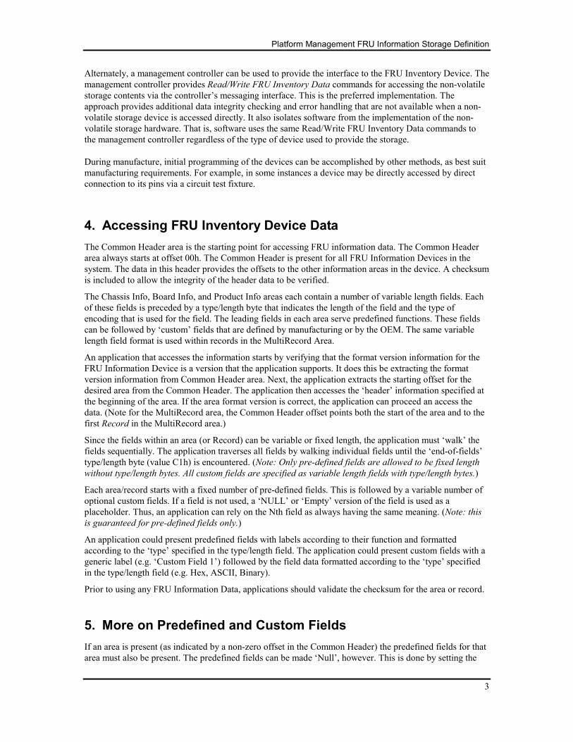
Alternately, a management controller can be used to provide the interface to the FRU Inventory Device. The
management controller provides Read/Write FRU Inventory Data commands for accessing the non-volatile
storage contents via the controller’s messaging interface. This is the preferred implementation. The
approach provides additional data integrity checking and error handling that are not available when a non-
volatile storage device is accessed directly. It also isolates software from the implementation of the non-
volatile storage hardware. That is, software uses the same Read/Write FRU Inventory Data commands to
the management controller regardless of the type of device used to provide the storage.
During manufacture, initial programming of the devices can be accomplished by other methods, as best suit
manufacturing requirements. For example, in some instances a device may be directly accessed by direct
connection to its pins via a circuit test fixture.
4. Accessing FRU Inventory Device Data
The Common Header area is the starting point for accessing FRU information data. The Common Header
area always starts at offset 00h. The Common Header is present for all FRU Information Devices in the
system. The data in this header provides the offsets to the other information areas in the device. A checksum
is included to allow the integrity of the header data to be verified.
The Chassis Info, Board Info, and Product Info areas each contain a number of variable length fields. Each
of these fields is preceded by a type/length byte that indicates the length of the field and the type of
encoding that is used for the field. The leading fields in each area serve predefined functions. These fields
can be followed by ‘custom’ fields that are defined by manufacturing or by the OEM. The same variable
length field format is used within records in the MultiRecord Area.
An application that accesses the information starts by verifying that the format version information for the
FRU Information Device is a version that the application supports. It does this be extracting the format
version information from Common Header area. Next, the application extracts the starting offset for the
desired area from the Common Header. The application then accesses the ‘header’ information specified at
the beginning of the area. If the area format version is correct, the application can proceed an access the
data. (Note for the MultiRecord area, the Common Header offset points both the start of the area and to the
first Record in the MultiRecord area.)
Since the fields within an area (or Record) can be variable or fixed length, the application must ‘walk’ the
fields sequentially. The application traverses all fields by walking individual fields until the ‘end-of-fields’
type/length byte (value C1h) is encountered. (Note: Only pre-defined fields are allowed to be fixed length
without type/length bytes. All custom fields are specified as variable length fields with type/length bytes.)
Each area/record starts with a fixed number of pre-defined fields. This is followed by a variable number of
optional custom fields. If a field is not used, a ‘NULL’ or ‘Empty’ version of the field is used as a
placeholder. Thus, an application can rely on the Nth field as always having the same meaning. (Note: this
is guaranteed for pre-defined fields only.)
An application could present predefined fields with labels according to their function and formatted
according to the ‘type’ specified in the type/length field. The application could present custom fields with a
generic label (e.g. ‘Custom Field 1’) followed by the field data formatted according to the ‘type’ specified
in the type/length field (e.g. Hex, ASCII, Binary).
Prior to using any FRU Information Data, applications should validate the checksum for the area or record.
5. More on Predefined and Custom Fields
If an area is present (as indicated by a non-zero offset in the Common Header) the predefined fields for that
area must also be present. The predefined fields can be made ‘Null’, however. This is done by setting the

Platform Management FRU Information Storage Definition
4
type/length byte to “xx000000” to indicate that the field has no data. All pre-defined fields must be present
regardless of whether they are ‘Null’ or not. Custom fields must always be preceded with a type/length byte.
The ‘end-of-fields’ byte and area checksum are also required.
Platform Management FRU Information Storage Definition
5
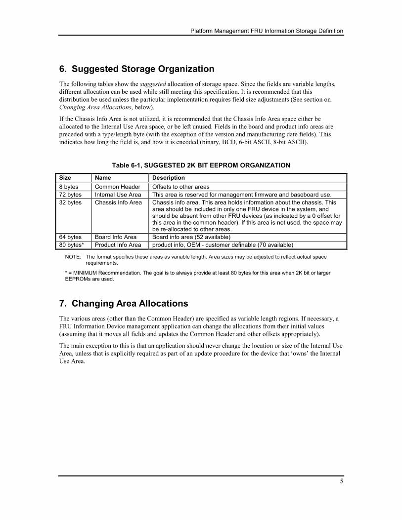
6. Suggested Storage Organization
The following tables show the suggested allocation of storage space. Since the fields are variable lengths,
different allocation can be used while still meeting this specification. It is recommended that this
distribution be used unless the particular implementation requires field size adjustments (See section on
Changing Area Allocations, below).
If the Chassis Info Area is not utilized, it is recommended that the Chassis Info Area space either be
allocated to the Internal Use Area space, or be left unused. Fields in the board and product info areas are
preceded with a type/length byte (with the exception of the version and manufacturing date fields). This
indicates how long the field is, and how it is encoded (binary, BCD, 6-bit ASCII, 8-bit ASCII).
Table 6-1, SUGGESTED 2K BIT EEPROM ORGANIZATION
Size Name Description
8 bytes Common Header Offsets to other areas
72 bytes Internal Use Area This area is reserved for management firmware and baseboard use.
32 bytes Chassis Info Area Chassis info area. This area holds information about the chassis. This area should be included in only one FRU device in the system, and should be absent from other FRU devices (as indicated by a 0 offset for this area in the common header). If this area is not used, the space may be re-allocated to other areas.
64 bytes Board Info Area Board info area (52 available)
80 bytes* Product Info Area product info, OEM - customer definable (70 available)
NOTE: The format specifies these areas as variable length. Area sizes may be adjusted to reflect actual space requirements.
* = MINIMUM Recommendation. The goal is to always provide at least 80 bytes for this area when 2K bit or larger EEPROMs are used.
7. Changing Area Allocations
The various areas (other than the Common Header) are specified as variable length regions. If necessary, a
FRU Information Device management application can change the allocations from their initial values
(assuming that it moves all fields and updates the Common Header and other offsets appropriately).
The main exception to this is that an application should never change the location or size of the Internal Use
Area, unless that is explicitly required as part of an update procedure for the device that ‘owns’ the Internal
Use Area.
Platform Management FRU Information Storage Definition
6
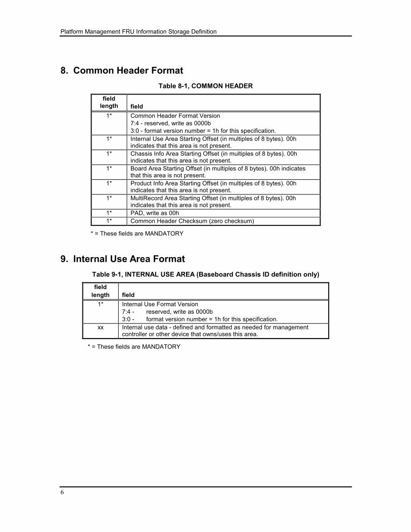
8. Common Header Format
Table 8-1, COMMON HEADER
field
length
field
1* Common Header Format Version
7:4 - reserved, write as 0000b
3:0 - format version number = 1h for this specification.
1* Internal Use Area Starting Offset (in multiples of 8 bytes). 00h indicates that this area is not present.
1* Chassis Info Area Starting Offset (in multiples of 8 bytes). 00h indicates that this area is not present.
1* Board Area Starting Offset (in multiples of 8 bytes). 00h indicates that this area is not present.
1* Product Info Area Starting Offset (in multiples of 8 bytes). 00h indicates that this area is not present.
1* MultiRecord Area Starting Offset (in multiples of 8 bytes). 00h indicates that this area is not present.
1* PAD, write as 00h
1* Common Header Checksum (zero checksum)
* = These fields are MANDATORY
9. Internal Use Area Format
Table 9-1, INTERNAL USE AREA (Baseboard Chassis ID definition only)
field
length
field
1* Internal Use Format Version
7:4 - reserved, write as 0000b
3:0 - format version number = 1h for this specification.
xx Internal use data - defined and formatted as needed for management controller or other device that owns/uses this area.
* = These fields are MANDATORY
Platform Management FRU Information Storage Definition
7
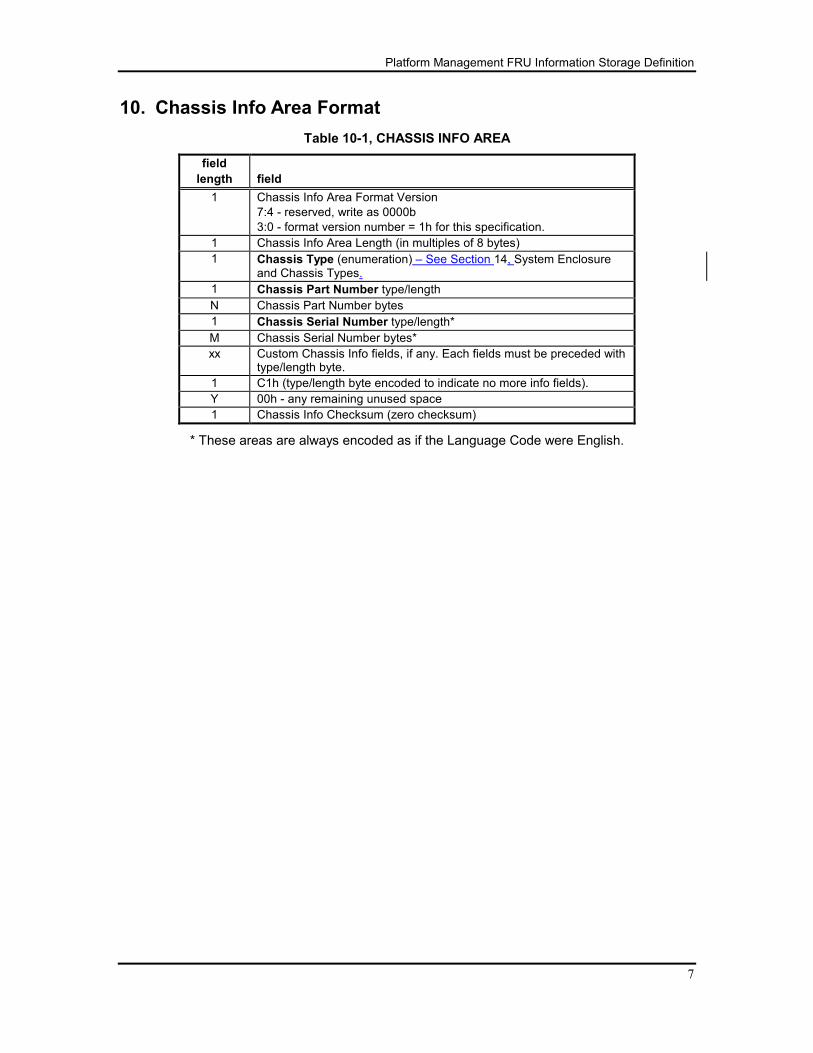
10. Chassis Info Area Format
Table 10-1, CHASSIS INFO AREA
field
length
field
1 Chassis Info Area Format Version
7:4 - reserved, write as 0000b
3:0 - format version number = 1h for this specification.
1 Chassis Info Area Length (in multiples of 8 bytes)
1 Chassis Type (enumeration) – See Section 14, System Enclosure and Chassis Types.
1 Chassis Part Number type/length
N Chassis Part Number bytes
1 Chassis Serial Number type/length*
M Chassis Serial Number bytes*
xx Custom Chassis Info fields, if any. Each fields must be preceded with type/length byte.
1 C1h (type/length byte encoded to indicate no more info fields).
Y 00h - any remaining unused space
1 Chassis Info Checksum (zero checksum)
* These areas are always encoded as if the Language Code were English.
Platform Management FRU Information Storage Definition
8
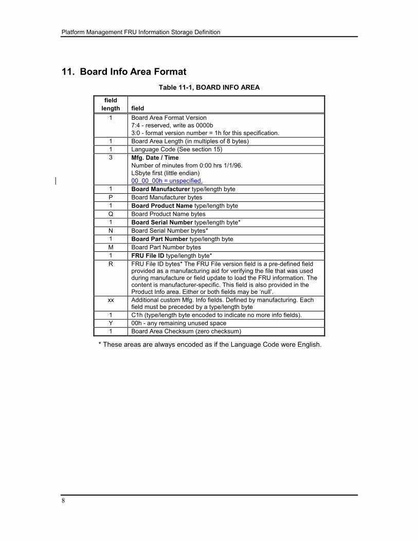
11. Board Info Area Format
Table 11-1, BOARD INFO AREA
field
length
field
1 Board Area Format Version
7:4 - reserved, write as 0000b
3:0 - format version number = 1h for this specification.
1 Board Area Length (in multiples of 8 bytes)
1 Language Code (See section 15)
3 Mfg. Date / Time
Number of minutes from 0:00 hrs 1/1/96.
LSbyte first (little endian)
00_00_00h = unspecified.
1 Board Manufacturer type/length byte
P Board Manufacturer bytes
1 Board Product Name type/length byte
Q Board Product Name bytes
1 Board Serial Number type/length byte*
N Board Serial Number bytes*
1 Board Part Number type/length byte
M Board Part Number bytes
1 FRU File ID type/length byte*
R FRU File ID bytes* The FRU File version field is a pre-defined field provided as a manufacturing aid for verifying the file that was used during manufacture or field update to load the FRU information. The content is manufacturer-specific. This field is also provided in the Product Info area. Either or both fields may be ‘null’.
xx Additional custom Mfg. Info fields. Defined by manufacturing. Each field must be preceded by a type/length byte
1 C1h (type/length byte encoded to indicate no more info fields).
Y 00h - any remaining unused space
1 Board Area Checksum (zero checksum)
* These areas are always encoded as if the Language Code were English.
Platform Management FRU Information Storage Definition
9
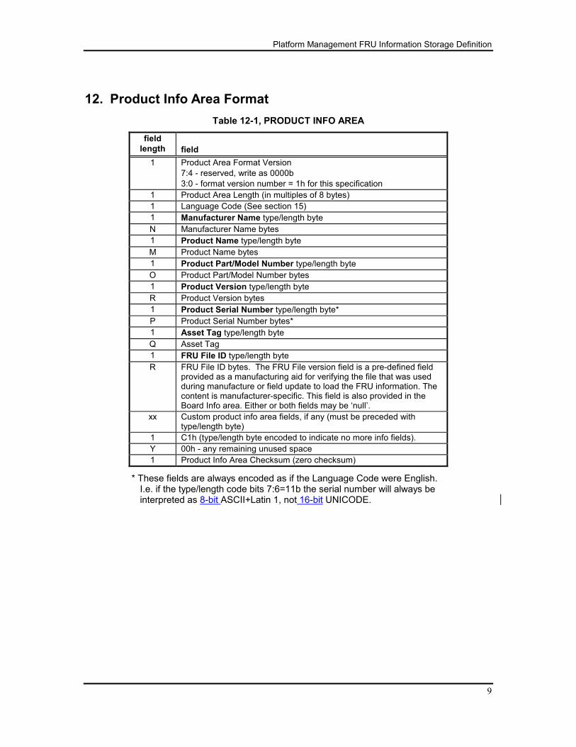
12. Product Info Area Format
Table 12-1, PRODUCT INFO AREA
field
length
field
1 Product Area Format Version
7:4 - reserved, write as 0000b
3:0 - format version number = 1h for this specification
1 Product Area Length (in multiples of 8 bytes)
1 Language Code (See section 15)
1 Manufacturer Name type/length byte
N Manufacturer Name bytes
1 Product Name type/length byte
M Product Name bytes
1 Product Part/Model Number type/length byte
O Product Part/Model Number bytes
1 Product Version type/length byte
R Product Version bytes
1 Product Serial Number type/length byte*
P Product Serial Number bytes*
1 Asset Tag type/length byte
Q Asset Tag
1 FRU File ID type/length byte
R FRU File ID bytes. The FRU File version field is a pre-defined field provided as a manufacturing aid for verifying the file that was used during manufacture or field update to load the FRU information. The content is manufacturer-specific. This field is also provided in the Board Info area. Either or both fields may be ‘null’.
xx Custom product info area fields, if any (must be preceded with type/length byte)
1 C1h (type/length byte encoded to indicate no more info fields).
Y 00h - any remaining unused space
1 Product Info Area Checksum (zero checksum)
* These fields are always encoded as if the Language Code were English. I.e. if the type/length code bits 7:6=11b the serial number will always be interpreted as 8-bit ASCII+Latin 1, not 16-bit UNICODE.
Platform Management FRU Information Storage Definition
10
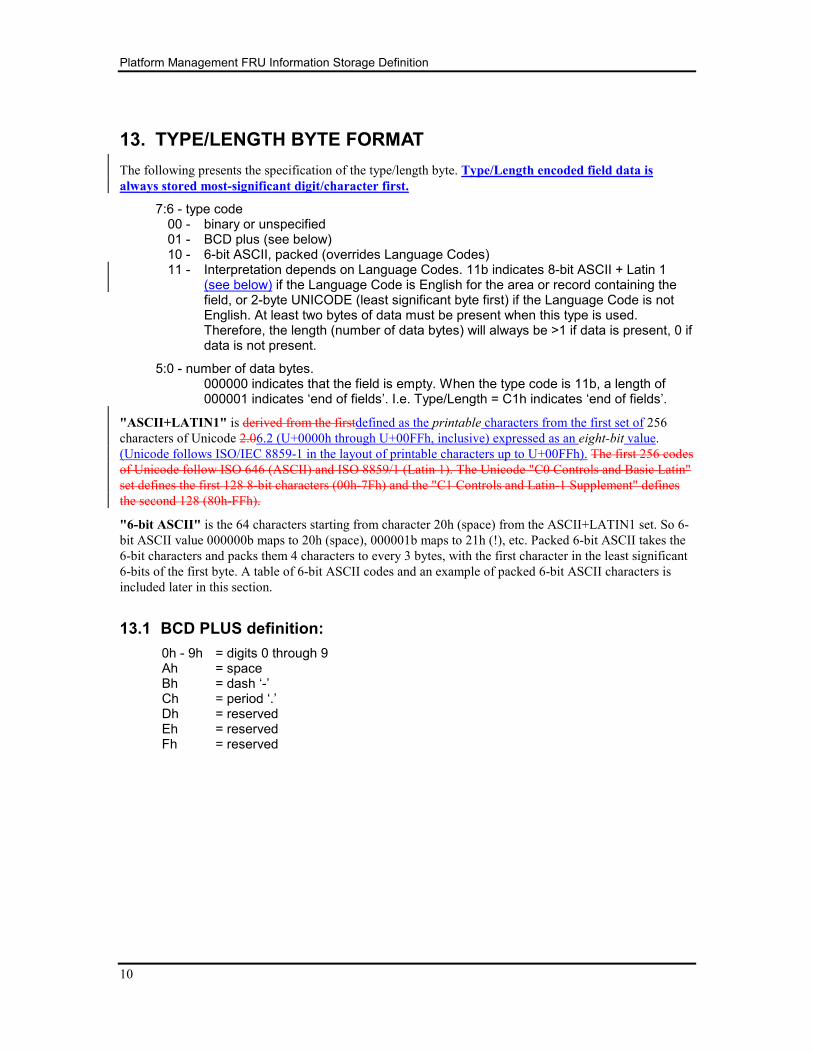
13. TYPE/LENGTH BYTE FORMAT
The following presents the specification of the type/length byte. Type/Length encoded field data is
always stored most-significant digit/character first.
7:6 - type code 00 - binary or unspecified 01 - BCD plus (see below) 10 - 6-bit ASCII, packed (overrides Language Codes) 11 - Interpretation depends on Language Codes. 11b indicates 8-bit ASCII + Latin 1
(see below) if the Language Code is English for the area or record containing the field, or 2-byte UNICODE (least significant byte first) if the Language Code is not English. At least two bytes of data must be present when this type is used. Therefore, the length (number of data bytes) will always be >1 if data is present, 0 if data is not present.
5:0 - number of data bytes. 000000 indicates that the field is empty. When the type code is 11b, a length of
000001 indicates ‘end of fields’. I.e. Type/Length = C1h indicates ‘end of fields’.
"ASCII+LATIN1" is derived from the firstdefined as the printable characters from the first set of 256
characters of Unicode 2.06.2 (U+0000h through U+00FFh, inclusive) expressed as an eight-bit value.
(Unicode follows ISO/IEC 8859-1 in the layout of printable characters up to U+00FFh). The first 256 codes
of Unicode follow ISO 646 (ASCII) and ISO 8859/1 (Latin 1). The Unicode "C0 Controls and Basic Latin"
set defines the first 128 8-bit characters (00h-7Fh) and the "C1 Controls and Latin-1 Supplement" defines
the second 128 (80h-FFh).
"6-bit ASCII" is the 64 characters starting from character 20h (space) from the ASCII+LATIN1 set. So 6-
bit ASCII value 000000b maps to 20h (space), 000001b maps to 21h (!), etc. Packed 6-bit ASCII takes the
6-bit characters and packs them 4 characters to every 3 bytes, with the first character in the least significant
6-bits of the first byte. A table of 6-bit ASCII codes and an example of packed 6-bit ASCII characters is
included later in this section.
13.1 BCD PLUS definition:
0h - 9h = digits 0 through 9 Ah = space Bh = dash ‘-’ Ch = period ‘.’ Dh = reserved Eh = reserved Fh = reserved
Platform Management FRU Information Storage Definition
11
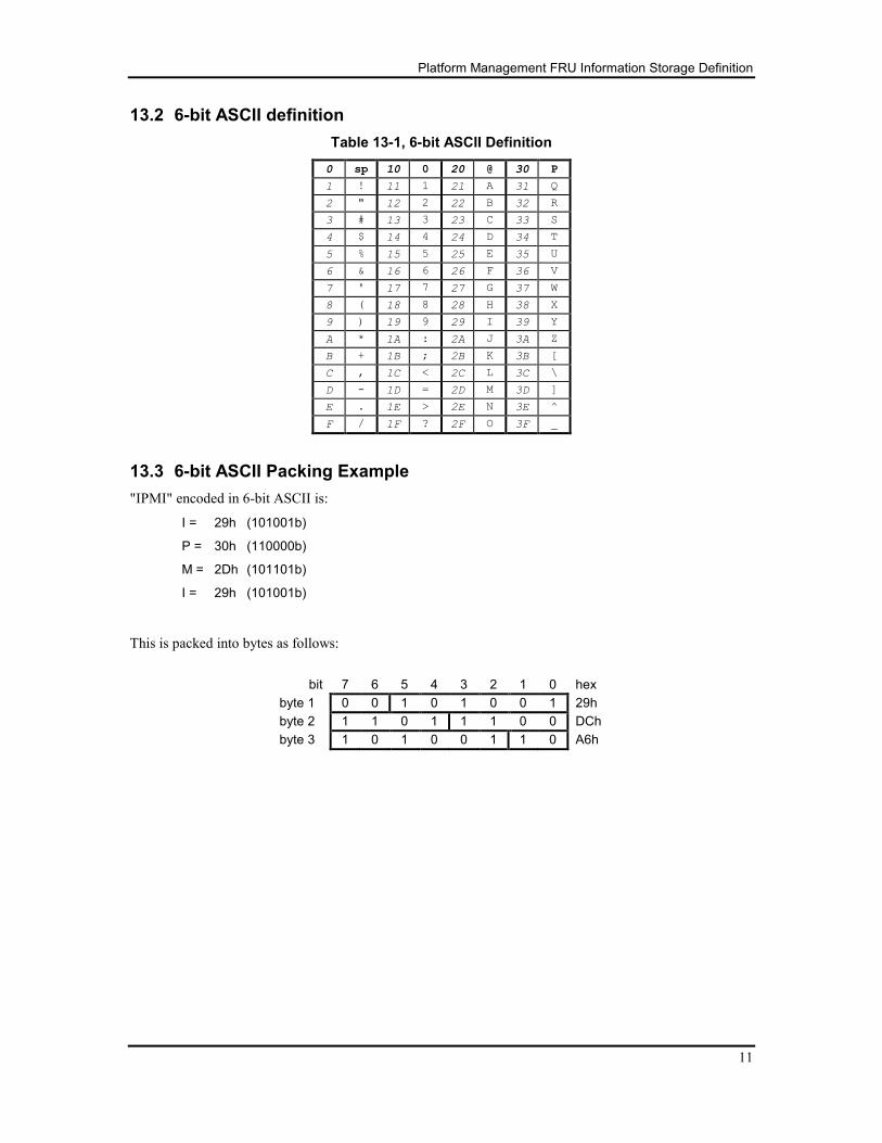
13.2 6-bit ASCII definition
Table 13-1, 6-bit ASCII Definition
0 sp 10 0 20 @ 30 P
1 ! 11 1 21 A 31 Q
2 " 12 2 22 B 32 R
3 # 13 3 23 C 33 S
4 $ 14 4 24 D 34 T
5 % 15 5 25 E 35 U
6 & 16 6 26 F 36 V
7 ' 17 7 27 G 37 W
8 ( 18 8 28 H 38 X
9 ) 19 9 29 I 39 Y
A * 1A : 2A J 3A Z
B + 1B ; 2B K 3B [
C , 1C < 2C L 3C \
D - 1D = 2D M 3D ]
E . 1E > 2E N 3E ^
F / 1F ? 2F O 3F _
13.3 6-bit ASCII Packing Example
"IPMI" encoded in 6-bit ASCII is:
I = 29h (101001b)
P = 30h (110000b)
M = 2Dh (101101b)
I = 29h (101001b)
This is packed into bytes as follows:
bit 7 6 5 4 3 2 1 0 hex
byte 1 0 0 1 0 1 0 0 1 29h
byte 2 1 1 0 1 1 1 0 0 DCh
byte 3 1 0 1 0 0 1 1 0 A6h

Platform Management FRU Information Storage Definition
12
14. System Enclosure and Chassis Types
The enumeration values for System Enclosure and Chassis Types is defined in the [SMBIOS] specification,
Table 16 – System Enclosure or Chassis Types.
Platform Management FRU Information Storage Definition
13
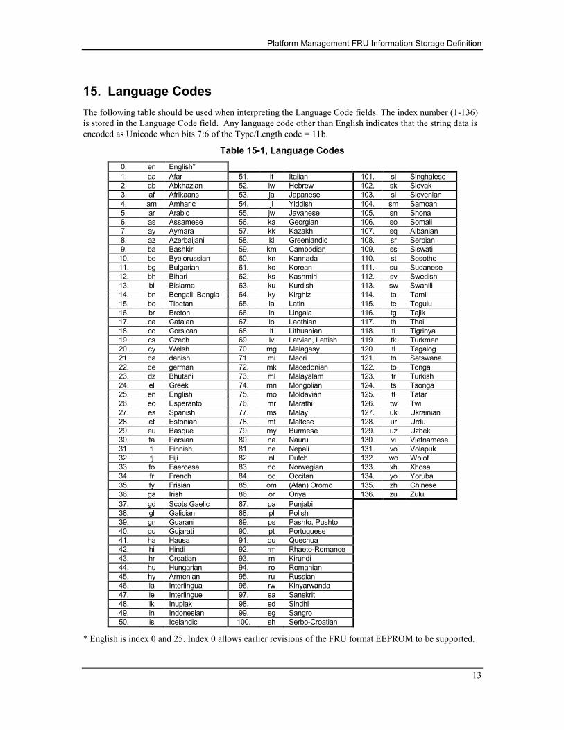
15. Language Codes
The following table should be used when interpreting the Language Code fields. The index number (1-136)
is stored in the Language Code field. Any language code other than English indicates that the string data is
encoded as Unicode when bits 7:6 of the Type/Length code = 11b.
Table 15-1, Language Codes
0. en English*
1. aa Afar 51. it Italian 101. si Singhalese
2. ab Abkhazian 52. iw Hebrew 102. sk Slovak
3. af Afrikaans 53. ja Japanese 103. sl Slovenian
4. am Amharic 54. ji Yiddish 104. sm Samoan
5. ar Arabic 55. jw Javanese 105. sn Shona
6. as Assamese 56. ka Georgian 106. so Somali
7. ay Aymara 57. kk Kazakh 107. sq Albanian
8. az Azerbaijani 58. kl Greenlandic 108. sr Serbian
9. ba Bashkir 59. km Cambodian 109. ss Siswati
10. be Byelorussian 60. kn Kannada 110. st Sesotho
11. bg Bulgarian 61. ko Korean 111. su Sudanese
12. bh Bihari 62. ks Kashmiri 112. sv Swedish
13. bi Bislama 63. ku Kurdish 113. sw Swahili
14. bn Bengali; Bangla 64. ky Kirghiz 114. ta Tamil
15. bo Tibetan 65. la Latin 115. te Tegulu
16. br Breton 66. ln Lingala 116. tg Tajik
17. ca Catalan 67. lo Laothian 117. th Thai
18. co Corsican 68. lt Lithuanian 118. ti Tigrinya
19. cs Czech 69. lv Latvian, Lettish 119. tk Turkmen
20. cy Welsh 70. mg Malagasy 120. tl Tagalog
21. da danish 71. mi Maori 121. tn Setswana
22. de german 72. mk Macedonian 122. to Tonga
23. dz Bhutani 73. ml Malayalam 123. tr Turkish
24. el Greek 74. mn Mongolian 124. ts Tsonga
25. en English 75. mo Moldavian 125. tt Tatar
26. eo Esperanto 76. mr Marathi 126. tw Twi
27. es Spanish 77. ms Malay 127. uk Ukrainian
28. et Estonian 78. mt Maltese 128. ur Urdu
29. eu Basque 79. my Burmese 129. uz Uzbek
30. fa Persian 80. na Nauru 130. vi Vietnamese
31. fi Finnish 81. ne Nepali 131. vo Volapuk
32. fj Fiji 82. nl Dutch 132. wo Wolof
33. fo Faeroese 83. no Norwegian 133. xh Xhosa
34. fr French 84. oc Occitan 134. yo Yoruba
35. fy Frisian 85. om (Afan) Oromo 135. zh Chinese
36. ga Irish 86. or Oriya 136. zu Zulu
37. gd Scots Gaelic 87. pa Punjabi
38. gl Galician 88. pl Polish
39. gn Guarani 89. ps Pashto, Pushto
40. gu Gujarati 90. pt Portuguese
41. ha Hausa 91. qu Quechua
42. hi Hindi 92. rm Rhaeto-Romance
43. hr Croatian 93. rn Kirundi
44. hu Hungarian 94. ro Romanian
45. hy Armenian 95. ru Russian
46. ia Interlingua 96. rw Kinyarwanda
47. ie Interlingue 97. sa Sanskrit
48. ik Inupiak 98. sd Sindhi
49. in Indonesian 99. sg Sangro
50. is Icelandic 100. sh Serbo-Croatian
* English is index 0 and 25. Index 0 allows earlier revisions of the FRU format EEPROM to be supported.
Platform Management FRU Information Storage Definition
14
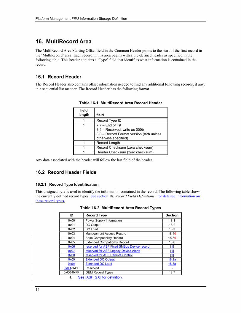
16. MultiRecord Area
The MultiRecord Area Starting Offset field in the Common Header points to the start of the first record in
the ‘MultiRecord’ area. Each record in this area begins with a pre-defined header as specified in the
following table. This header contains a ‘Type’ field that identifies what information is contained in the
record.
16.1 Record Header
The Record Header also contains offset information needed to find any additional following records, if any,
in a sequential list manner. The Record Header has the following format.
Table 16-1, MultiRecord Area Record Header
field
length
field
1 Record Type ID
1 7:7 – End of list
6:4 – Reserved, write as 000b
3:0 – Record Format version (=2h unless otherwise specified)
1 Record Length
1 Record Checksum (zero checksum)
1 Header Checksum (zero checksum)
Any data associated with the header will follow the last field of the header.
16.2 Record Header Fields
16.2.1 Record Type Identification
This unsigned byte is used to identify the information contained in the record. The following table shows
the currently defined record types. See section 18, Record Field Definitions , for detailed information on
these record types.
Table 16-2, MultiRecord Area Record Types
ID Record Type Section
0x00 Power Supply Information 18.1
0x01 DC Output 18.2
0x02 DC Load 18.3
0x03 Management Access Record 18.40
0x04 Base Compatibility Record 18.50
0x05 Extended Compatibility Record 18.6
0x06 reserved for ASF Fixed SMBus Device record. [1]
0x07 reserved for ASF Legacy-Device Alerts [1]
0x08 reserved for ASF Remote Control [1]
0x09 Extended DC Output 18.2a
0x0A Extended DC Load 18.3a
0x0B-0xBF Reserved -
0xC0-0xFF OEM Record Types 18.7
1. See [ASF_2.0] for definition.
Platform Management FRU Information Storage Definition
15
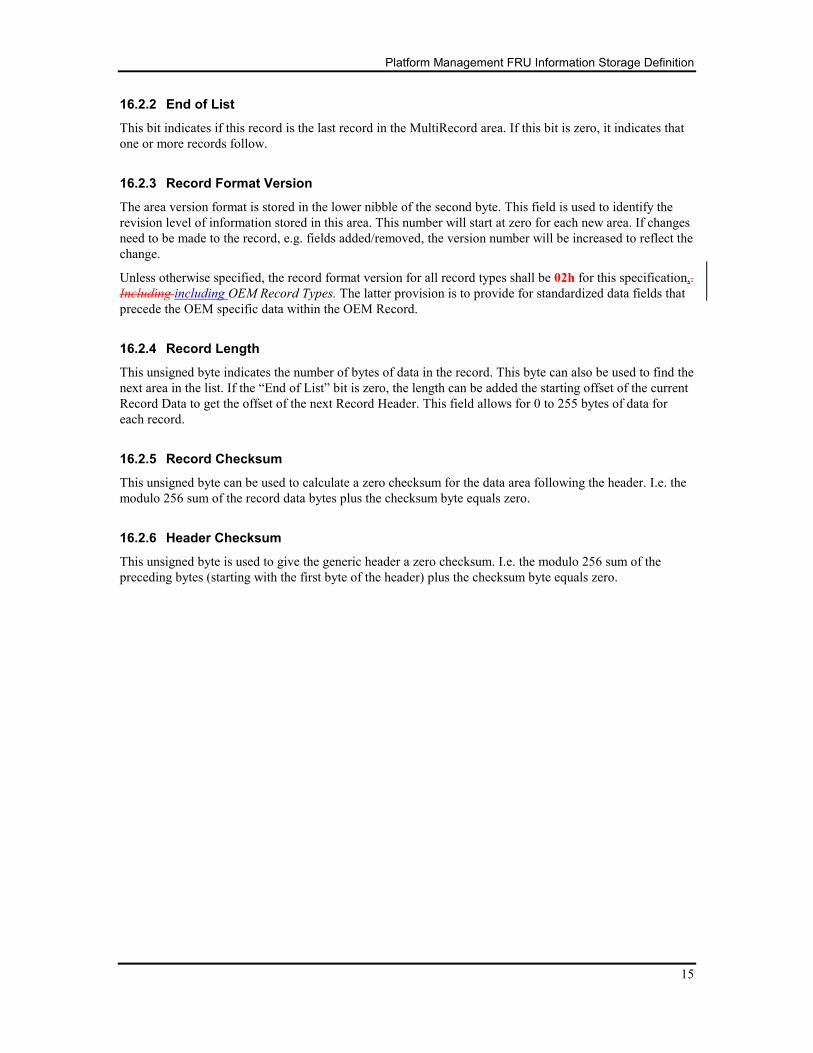
16.2.2 End of List
This bit indicates if this record is the last record in the MultiRecord area. If this bit is zero, it indicates that
one or more records follow.
16.2.3 Record Format Version
The area version format is stored in the lower nibble of the second byte. This field is used to identify the
revision level of information stored in this area. This number will start at zero for each new area. If changes
need to be made to the record, e.g. fields added/removed, the version number will be increased to reflect the
change.
Unless otherwise specified, the record format version for all record types shall be 02h for this specification,.
Including including OEM Record Types. The latter provision is to provide for standardized data fields that
precede the OEM specific data within the OEM Record.
16.2.4 Record Length
This unsigned byte indicates the number of bytes of data in the record. This byte can also be used to find the
next area in the list. If the “End of List” bit is zero, the length can be added the starting offset of the current
Record Data to get the offset of the next Record Header. This field allows for 0 to 255 bytes of data for
each record.
16.2.5 Record Checksum
This unsigned byte can be used to calculate a zero checksum for the data area following the header. I.e. the
modulo 256 sum of the record data bytes plus the checksum byte equals zero.
16.2.6 Header Checksum
This unsigned byte is used to give the generic header a zero checksum. I.e. the modulo 256 sum of the
preceding bytes (starting with the first byte of the header) plus the checksum byte equals zero.
Platform Management FRU Information Storage Definition
16
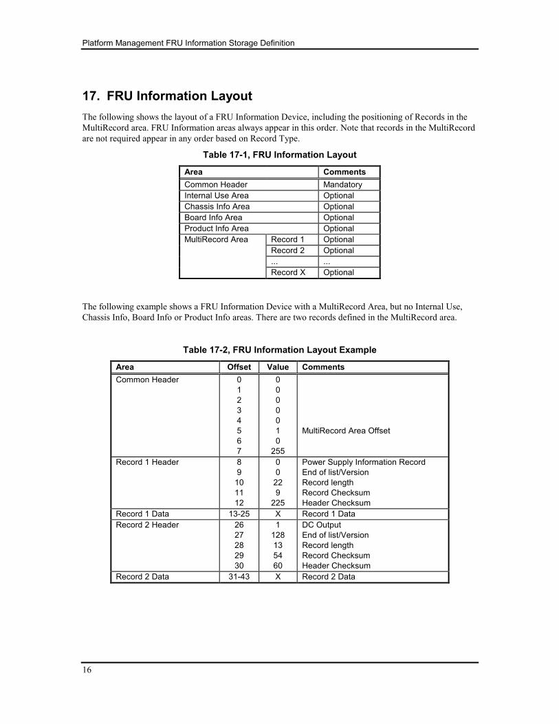
17. FRU Information Layout
The following shows the layout of a FRU Information Device, including the positioning of Records in the
MultiRecord area. FRU Information areas always appear in this order. Note that records in the MultiRecord
are not required appear in any order based on Record Type.
Table 17-1, FRU Information Layout
Area Comments
Common Header Mandatory
Internal Use Area Optional
Chassis Info Area Optional
Board Info Area Optional
Product Info Area Optional
MultiRecord Area Record 1 Optional
Record 2 Optional
... ...
Record X Optional
The following example shows a FRU Information Device with a MultiRecord Area, but no Internal Use,
Chassis Info, Board Info or Product Info areas. There are two records defined in the MultiRecord area.
Table 17-2, FRU Information Layout Example
Area Offset Value Comments
Common Header 0
1
2
3
4
5
6
7
0
0
0
0
0
1
0
255
MultiRecord Area Offset
Record 1 Header 8
9
10
11
12
0
0
22
9
225
Power Supply Information Record
End of list/Version
Record length
Record Checksum
Header Checksum
Record 1 Data 13-25 X Record 1 Data
Record 2 Header 26
27
28
29
30
1
128
13
54
60
DC Output
End of list/Version
Record length
Record Checksum
Header Checksum
Record 2 Data 31-43 X Record 2 Data
Platform Management FRU Information Storage Definition
17
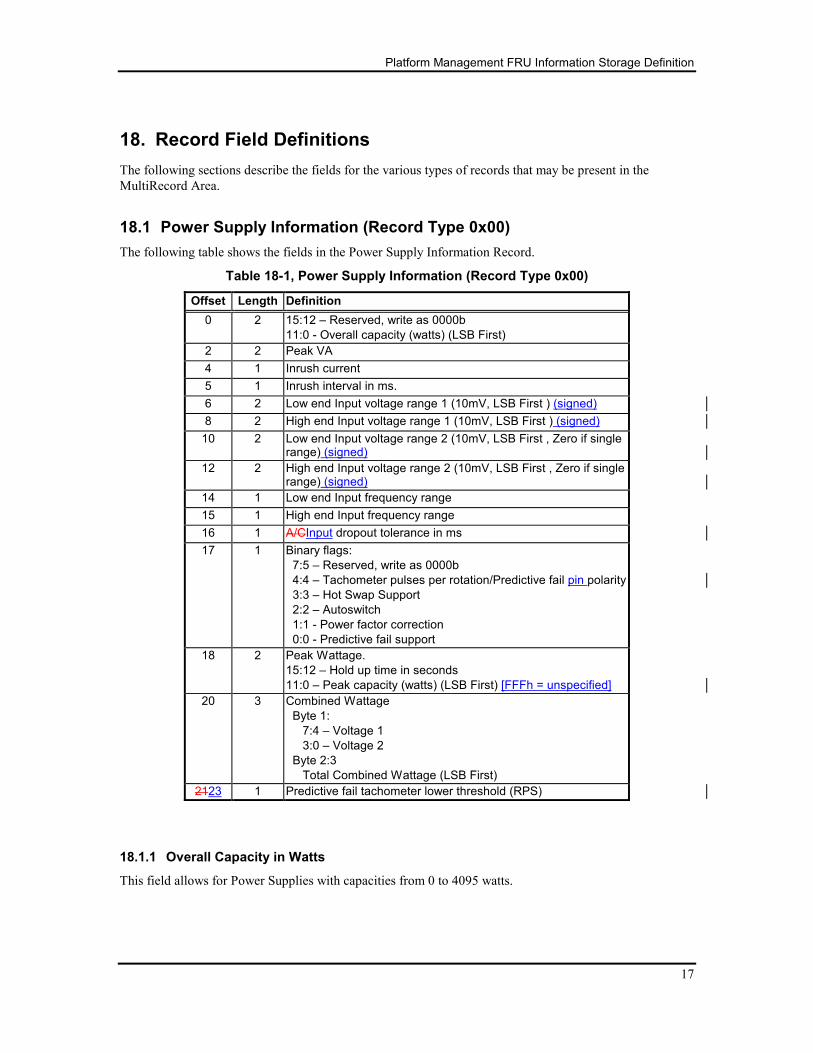
18. Record Field Definitions
The following sections describe the fields for the various types of records that may be present in the
MultiRecord Area.
18.1 Power Supply Information (Record Type 0x00)
The following table shows the fields in the Power Supply Information Record.
Table 18-1, Power Supply Information (Record Type 0x00)
Offset Length Definition
0 2 15:12 – Reserved, write as 0000b
11:0 - Overall capacity (watts) (LSB First)
2 2 Peak VA
4 1 Inrush current
5 1 Inrush interval in ms.
6 2 Low end Input voltage range 1 (10mV, LSB First ) (signed)
8 2 High end Input voltage range 1 (10mV, LSB First ) (signed)
10 2 Low end Input voltage range 2 (10mV, LSB First , Zero if single range) (signed)
12 2 High end Input voltage range 2 (10mV, LSB First , Zero if single range) (signed)
14 1 Low end Input frequency range
15 1 High end Input frequency range
16 1 A/CInput dropout tolerance in ms
17 1 Binary flags:
7:5 – Reserved, write as 0000b
4:4 – Tachometer pulses per rotation/Predictive fail pin polarity
3:3 – Hot Swap Support
2:2 – Autoswitch
1:1 - Power factor correction
0:0 - Predictive fail support
18 2 Peak Wattage.
15:12 – Hold up time in seconds
11:0 – Peak capacity (watts) (LSB First) [FFFh = unspecified]
20 3 Combined Wattage
Byte 1:
7:4 – Voltage 1
3:0 – Voltage 2
Byte 2:3
Total Combined Wattage (LSB First)
2123 1 Predictive fail tachometer lower threshold (RPS)
18.1.1 Overall Capacity in Watts
This field allows for Power Supplies with capacities from 0 to 4095 watts.
Platform Management FRU Information Storage Definition
18
18.1.2 Peak VA
The highest instantaneous VA value that this supply draws during operation (other than during Inrush). In
integer units. FFFFh if not specified.
18.1.3 Inrush
Maximum inrush of current, in Amps, into the power supply. FFh if not specified.
18.1.4 Inrush interval
Number of milliseconds before power supply loading enters non-startup operating range. Set to 0 if no
inrush current specified.
18.1.5 Low end Input voltage range 1
This specifies the low end of acceptable voltage into the power supply. The units are 10mV.
18.1.6 High end Input voltage range 1
This specifies the high end of acceptable voltage into the power supply. The units are 10mV.
18.1.7 Low end Input voltage range 2
This specifies the low end of acceptable voltage into the power supply. This field would be used if the
power supply did not support autoswitch. Range 1 would define the 110V range, while range 2 would be
used for 220V. The units are 10mV.
18.1.8 High end Input voltage range 2
This specifies the high end of acceptable voltage into the power supply. This field would be used if the
power supply did not support autoswitch. Range 1 would define the 110V range, while range 2 would be
used for 220V. The units are 10mV.
18.1.9 Low end input frequency range
This specifies the low end of acceptable frequency range into the power supply. Use 00h if supply accepts a
DC input.
18.1.10 High end input frequency range
This specifies the high end of acceptable frequency range into the power supply. Use 00h for both Low End
and High End frequency range if supply only takes a DC input.
18.1.11 A/CInput dropout tolerance
Minimum number of milliseconds the power supply can hold up POWERGOOD (and maintain valid DC
output) after input power is lost.
18.1.12 Binary flags
18.1.12.1 Tachometer pulses per rotation/Predictive fail polarity
The power supply can support predictive fail in two ways. The predictive fail pin could be a pass/fail signal
Platform Management FRU Information Storage Definition
19
or the tachometer output of the power supply fan. This field has a dual meaning depending on what the
power supply supports. See section 18.1.15 and 18.1.12.2 for more information.
Tachometer predictive fail signal:
0 – One pulse per rotation
1 – Two pulses per rotation
Pass/fail predictive fail signal:
0 – The signal asserted (1) indicates failure
1 – The signal de-asserted (0) indicates failure.
18.1.12.2 Other Binary flags
For each of the following binary flags 0=No, 1=Yes.
• Hot Swap supported
• Autoswitch supported
• Power factor correction supported
• Predictive fail pin supported
18.1.13 Peak Wattage
The high 4 bits indicates the number of seconds peak wattage can be sustained (0-15 seconds). The lower
12 bits indicate the peak wattage the power supply can produce during this time period (0-4095 watts).
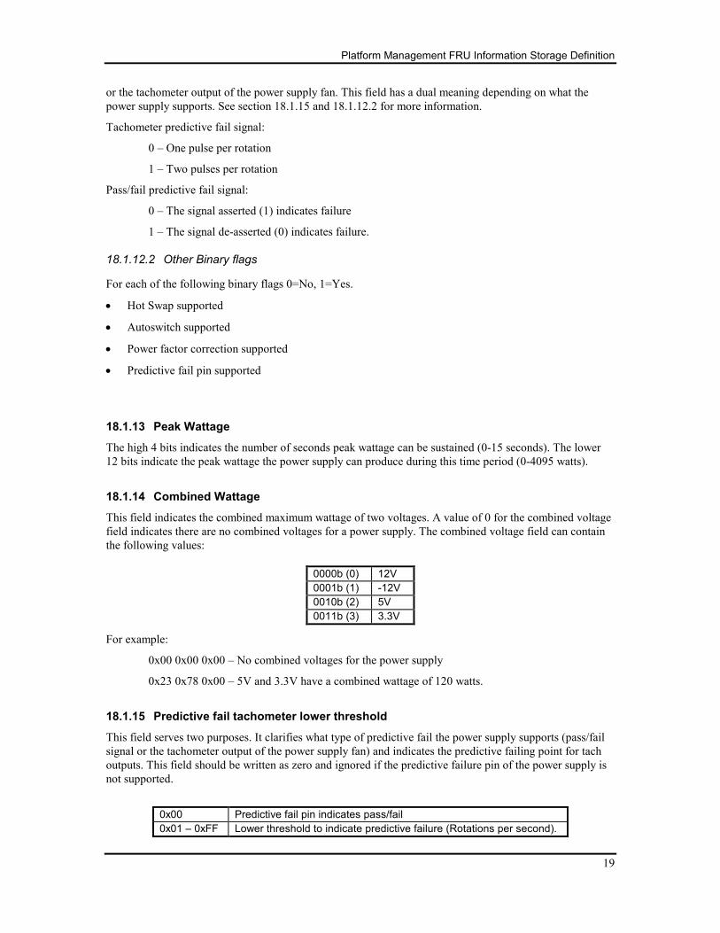
18.1.14 Combined Wattage
This field indicates the combined maximum wattage of two voltages. A value of 0 for the combined voltage
field indicates there are no combined voltages for a power supply. The combined voltage field can contain
the following values:
0000b (0) 12V
0001b (1) -12V
0010b (2) 5V
0011b (3) 3.3V
For example:
0x00 0x00 0x00 – No combined voltages for the power supply
0x23 0x78 0x00 – 5V and 3.3V have a combined wattage of 120 watts.
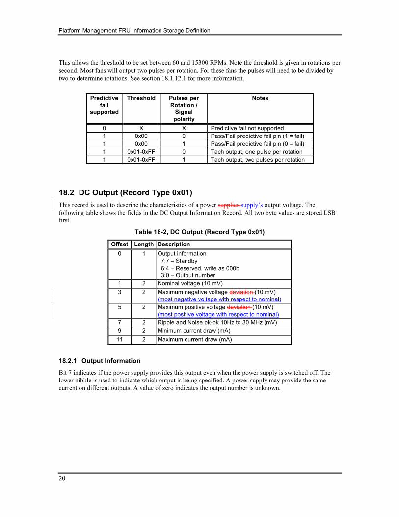
18.1.15 Predictive fail tachometer lower threshold
This field serves two purposes. It clarifies what type of predictive fail the power supply supports (pass/fail
signal or the tachometer output of the power supply fan) and indicates the predictive failing point for tach
outputs. This field should be written as zero and ignored if the predictive failure pin of the power supply is
not supported.
0x00 Predictive fail pin indicates pass/fail
0x01 – 0xFF Lower threshold to indicate predictive failure (Rotations per second).
Platform Management FRU Information Storage Definition
20
This allows the threshold to be set between 60 and 15300 RPMs. Note the threshold is given in rotations per
second. Most fans will output two pulses per rotation. For these fans the pulses will need to be divided by
two to determine rotations. See section 18.1.12.1 for more information.
Predictive
fail
supported
Threshold Pulses per
Rotation /
Signal
polarity
Notes
0 X X Predictive fail not supported
1 0x00 0 Pass/Fail predictive fail pin (1 = fail)
1 0x00 1 Pass/Fail predictive fail pin (0 = fail)
1 0x01-0xFF 0 Tach output, one pulse per rotation
1 0x01-0xFF 1 Tach output, two pulses per rotation
18.2 DC Output (Record Type 0x01)
This record is used to describe the characteristics of a power supplies supply’s output voltage. The
following table shows the fields in the DC Output Information Record. All two byte values are stored LSB
first.
Table 18-2, DC Output (Record Type 0x01)
Offset Length Description
0 1 Output information
7:7 – Standby
6:4 – Reserved, write as 000b
3:0 – Output number
1 2 Nominal voltage (10 mV)
3 2 Maximum negative voltage deviation (10 mV)
(most negative voltage with respect to nominal)
5 2 Maximum positive voltage deviation (10 mV)
(most positive voltage with respect to nominal)
7 2 Ripple and Noise pk-pk 10Hz to 30 MHz (mV)
9 2 Minimum current draw (mA)
11 2 Maximum current draw (mA)
18.2.1 Output Information
Bit 7 indicates if the power supply provides this output even when the power supply is switched off. The
lower nibble is used to indicate which output is being specified. A power supply may provide the same
current on different outputs. A value of zero indicates the output number is unknown.
Platform Management FRU Information Storage Definition
21
18.2.2 Nominal voltage
Expected voltage from the power supply. Value is a signed short given in 10 millivolt increments. The
following table gives some example values.
Voltage Decimal Value Hex Value
+3.30V 330 0x014A
+12.00V 1200 0x04B0
-12.00V -1200 0xFB50
18.2.3 Maximum negative voltage deviation
Lowest rated voltage from the power output. Value is a signed short given in 10 millivolt increments.
18.2.4 Maximum positive voltage deviation
Highest rated voltage from the power output. Value is a signed short given in 10 millivolt increments.
18.2.5 Ripple and Noise pk-pk, 10Hz to 30MHz
Value given in mV. Voltage deviation below 10Hz is considered part of the Maximum negative and
Maximum Positive voltage deviation specifications.
18.2.6 Minimum current draw
Minimum output capabilities provided for this output. The value is given in milliamps.
18.2.7 Maximum current draw
Maximum output capabilities provided for this output. The value is given in milliamps.
Platform Management FRU Information Storage Definition
22
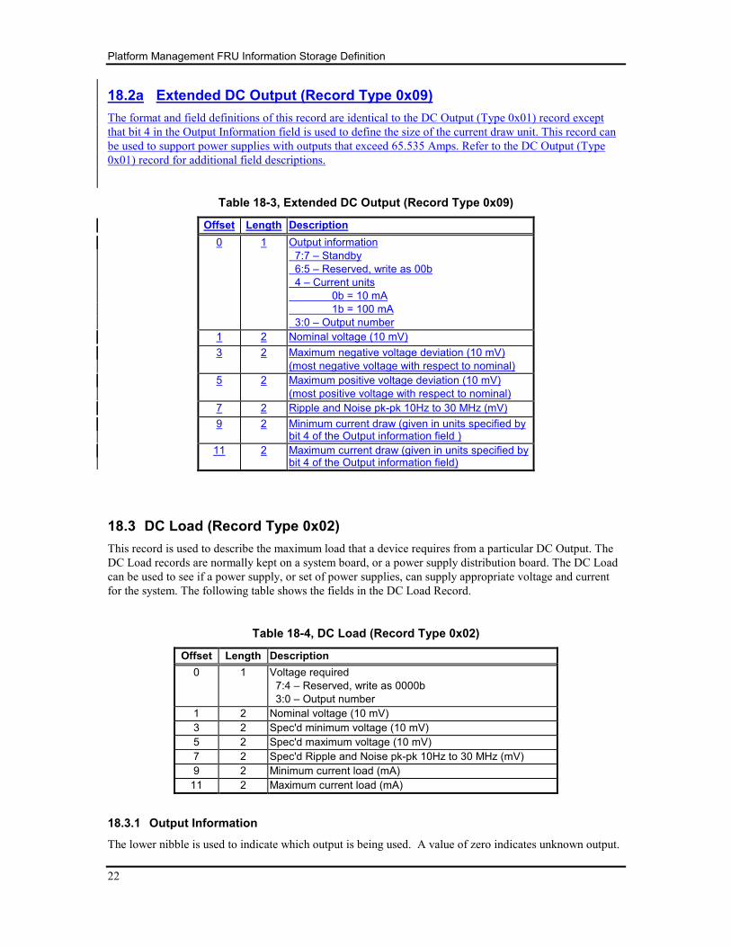
18.2a Extended DC Output (Record Type 0x09)
The format and field definitions of this record are identical to the DC Output (Type 0x01) record except
that bit 4 in the Output Information field is used to define the size of the current draw unit. This record can
be used to support power supplies with outputs that exceed 65.535 Amps. Refer to the DC Output (Type
0x01) record for additional field descriptions.
Table 18-3, Extended DC Output (Record Type 0x09)
Offset Length Description
0 1 Output information
7:7 – Standby
6:5 – Reserved, write as 00b
4 – Current units
0b = 10 mA
1b = 100 mA
3:0 – Output number
1 2 Nominal voltage (10 mV)
3 2 Maximum negative voltage deviation (10 mV)
(most negative voltage with respect to nominal)
5 2 Maximum positive voltage deviation (10 mV)
(most positive voltage with respect to nominal)
7 2 Ripple and Noise pk-pk 10Hz to 30 MHz (mV)
9 2 Minimum current draw (given in units specified by bit 4 of the Output information field )
11 2 Maximum current draw (given in units specified by bit 4 of the Output information field)
18.3 DC Load (Record Type 0x02)
This record is used to describe the maximum load that a device requires from a particular DC Output. The
DC Load records are normally kept on a system board, or a power supply distribution board. The DC Load
can be used to see if a power supply, or set of power supplies, can supply appropriate voltage and current
for the system. The following table shows the fields in the DC Load Record.
Table 18-4, DC Load (Record Type 0x02)
Offset Length Description
0 1 Voltage required
7:4 – Reserved, write as 0000b
3:0 – Output number
1 2 Nominal voltage (10 mV)
3 2 Spec'd minimum voltage (10 mV)
5 2 Spec'd maximum voltage (10 mV)
7 2 Spec'd Ripple and Noise pk-pk 10Hz to 30 MHz (mV)
9 2 Minimum current load (mA)
11 2 Maximum current load (mA)
18.3.1 Output Information
The lower nibble is used to indicate which output is being used. A value of zero indicates unknown output.
Platform Management FRU Information Storage Definition
23
18.3.2 Nominal voltage
Expected voltage from the power supply. Value is a signed short given in 10 millivolt increments.
18.3.3 Spec'd minimum voltage
Lowest tolerable voltage from the power supply. Value is a signed short given in 10 millivolt increments.
18.3.4 Spec'd maximum voltage
Highest tolerable voltage from the power supply. Value is a signed short given in 10 millivolt increments.
18.3.5 Ripple and Noise pk-pk 10Hz to 30MHz
Value given in mV.
18.3.6 Minimum current load
Minimum output load needed for this output to maintain specified regulation. The value is given in
milliamps.
18.3.7 Maximum current load
Maximum output load needed from this for this output to maintain specified regulation. The value is given
in milliamps.
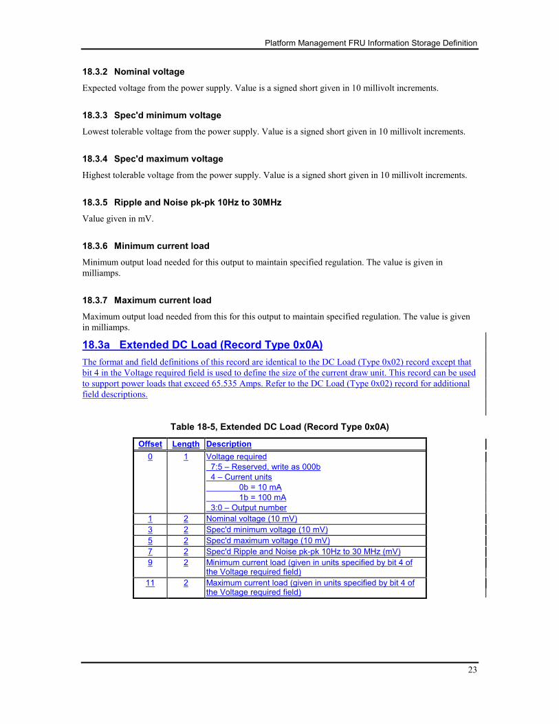
18.3a Extended DC Load (Record Type 0x0A)
The format and field definitions of this record are identical to the DC Load (Type 0x02) record except that
bit 4 in the Voltage required field is used to define the size of the current draw unit. This record can be used
to support power loads that exceed 65.535 Amps. Refer to the DC Load (Type 0x02) record for additional
field descriptions.
Table 18-5, Extended DC Load (Record Type 0x0A)
Offset Length Description
0 1 Voltage required
7:5 – Reserved, write as 000b
4 – Current units
0b = 10 mA
1b = 100 mA
3:0 – Output number
1 2 Nominal voltage (10 mV)
3 2 Spec'd minimum voltage (10 mV)
5 2 Spec'd maximum voltage (10 mV)
7 2 Spec'd Ripple and Noise pk-pk 10Hz to 30 MHz (mV)
9 2 Minimum current load (given in units specified by bit 4 of the Voltage required field)
11 2 Maximum current load (given in units specified by bit 4 of the Voltage required field)
Platform Management FRU Information Storage Definition
24
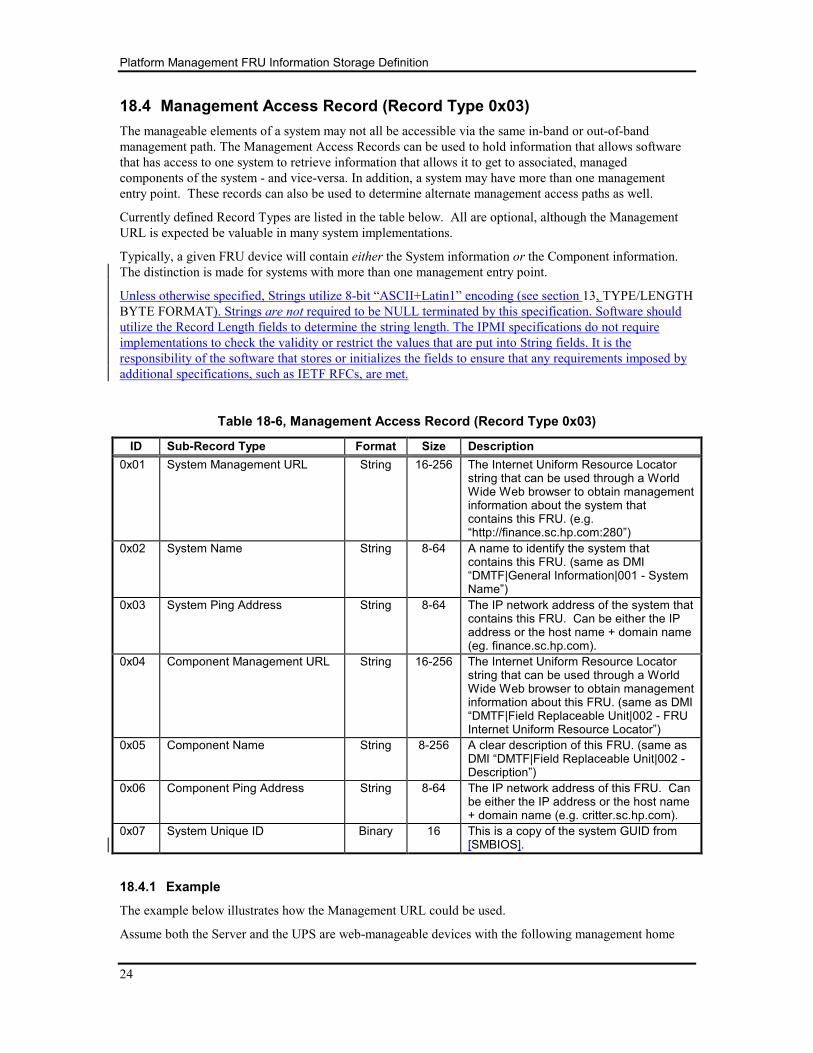
18.4 Management Access Record (Record Type 0x03)
The manageable elements of a system may not all be accessible via the same in-band or out-of-band
management path. The Management Access Records can be used to hold information that allows software
that has access to one system to retrieve information that allows it to get to associated, managed
components of the system - and vice-versa. In addition, a system may have more than one management
entry point. These records can also be used to determine alternate management access paths as well.
Currently defined Record Types are listed in the table below. All are optional, although the Management
URL is expected be valuable in many system implementations.
Typically, a given FRU device will contain either the System information or the Component information.
The distinction is made for systems with more than one management entry point.
Unless otherwise specified, Strings utilize 8-bit “ASCII+Latin1” encoding (see section 13, TYPE/LENGTH
BYTE FORMAT). Strings are not required to be NULL terminated by this specification. Software should
utilize the Record Length fields to determine the string length. The IPMI specifications do not require
implementations to check the validity or restrict the values that are put into String fields. It is the
responsibility of the software that stores or initializes the fields to ensure that any requirements imposed by
additional specifications, such as IETF RFCs, are met.
Table 18-6, Management Access Record (Record Type 0x03)
ID Sub-Record Type Format Size Description
0x01 System Management URL String 16-256 The Internet Uniform Resource Locator string that can be used through a World Wide Web browser to obtain management information about the system that contains this FRU. (e.g. “http://finance.sc.hp.com:280”)
0x02 System Name String 8-64 A name to identify the system that contains this FRU. (same as DMI “DMTF|General Information|001 - System Name”)
0x03 System Ping Address String 8-64 The IP network address of the system that contains this FRU. Can be either the IP address or the host name + domain name (eg. finance.sc.hp.com).
0x04 Component Management URL String 16-256 The Internet Uniform Resource Locator string that can be used through a World Wide Web browser to obtain management information about this FRU. (same as DMI “DMTF|Field Replaceable Unit|002 - FRU Internet Uniform Resource Locator”)
0x05 Component Name String 8-256 A clear description of this FRU. (same as DMI “DMTF|Field Replaceable Unit|002 - Description”)
0x06 Component Ping Address String 8-64 The IP network address of this FRU. Can be either the IP address or the host name + domain name (e.g. critter.sc.hp.com).
0x07 System Unique ID Binary 16 This is a copy of the system GUID from [SMBIOS].
18.4.1 Example
The example below illustrates how the Management URL could be used.
Assume both the Server and the UPS are web-manageable devices with the following management home
Platform Management FRU Information Storage Definition
25
pages:
Server (“Finance Server 2”) – http://finance.sc.hp.com:280
UPS (“Finance UPS”) – http://192.168.0.1
The Server’s management pages should include links to attached web-manageable devices such as the UPS.
The UPS pages could also include a link back to the Server. ICMB provides a standard interface to the
URLs of attached components via the FRU MultiRecord Area. An agent on the Server can then collect all
URLs of attached web-manageable devices using IPMI; likewise, the UPS’s management processor can
determine the Server’s URL using ICMB.
Using the data in the MultiRecord Areas (see below), the following HTML tags can be created
programmatically:
<A HREF= http://finance.sc.hp.com:280>Finance Server 2</A>
<A HREF= http://192.168.0.1>Finance UPS</A>
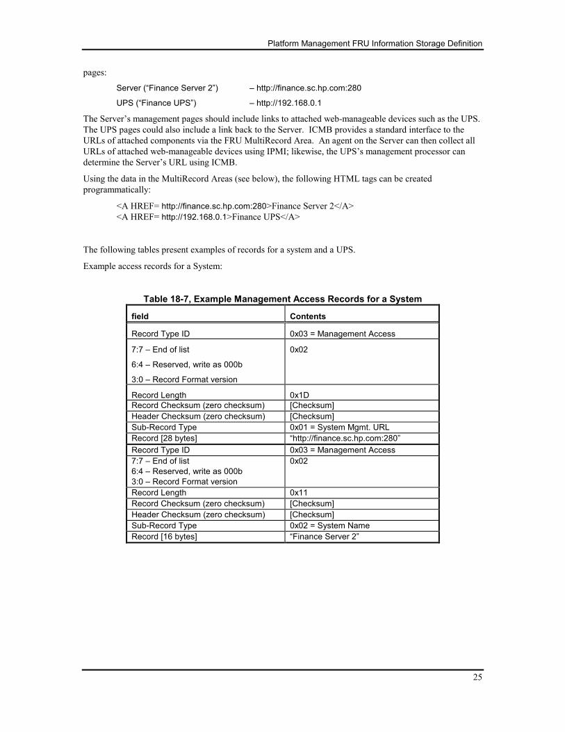
The following tables present examples of records for a system and a UPS.
Example access records for a System:
Table 18-7, Example Management Access Records for a System
field Contents
Record Type ID 0x03 = Management Access
7:7 – End of list
6:4 – Reserved, write as 000b
3:0 – Record Format version
0x02
Record Length 0x1D
Record Checksum (zero checksum) [Checksum]
Header Checksum (zero checksum) [Checksum]
Sub-Record Type 0x01 = System Mgmt. URL
Record [28 bytes] “http://finance.sc.hp.com:280”
Record Type ID 0x03 = Management Access
7:7 – End of list
6:4 – Reserved, write as 000b
3:0 – Record Format version
0x02
Record Length 0x11
Record Checksum (zero checksum) [Checksum]
Header Checksum (zero checksum) [Checksum]
Sub-Record Type 0x02 = System Name
Record [16 bytes] “Finance Server 2”
Platform Management FRU Information Storage Definition
26
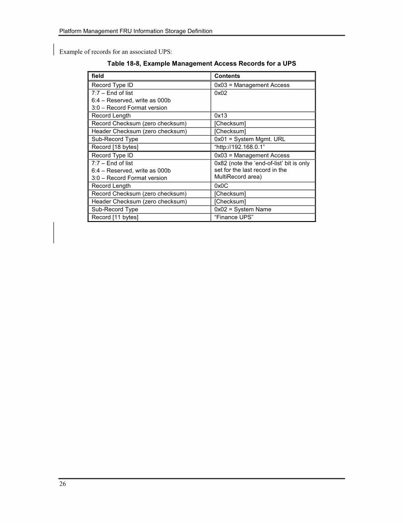
Example of records for an associated UPS:
Table 18-8, Example Management Access Records for a UPS
field Contents
Record Type ID 0x03 = Management Access
7:7 – End of list
6:4 – Reserved, write as 000b
3:0 – Record Format version
0x02
Record Length 0x13
Record Checksum (zero checksum) [Checksum]
Header Checksum (zero checksum) [Checksum]
Sub-Record Type 0x01 = System Mgmt. URL
Record [18 bytes] “http://192.168.0.1”
Record Type ID 0x03 = Management Access
7:7 – End of list
6:4 – Reserved, write as 000b
3:0 – Record Format version
0x82 (note the ‘end-of-list’ bit is only set for the last record in the MultiRecord area)
Record Length 0x0C
Record Checksum (zero checksum) [Checksum]
Header Checksum (zero checksum) [Checksum]
Sub-Record Type 0x02 = System Name
Record [11 bytes] “Finance UPS”
Platform Management FRU Information Storage Definition
27
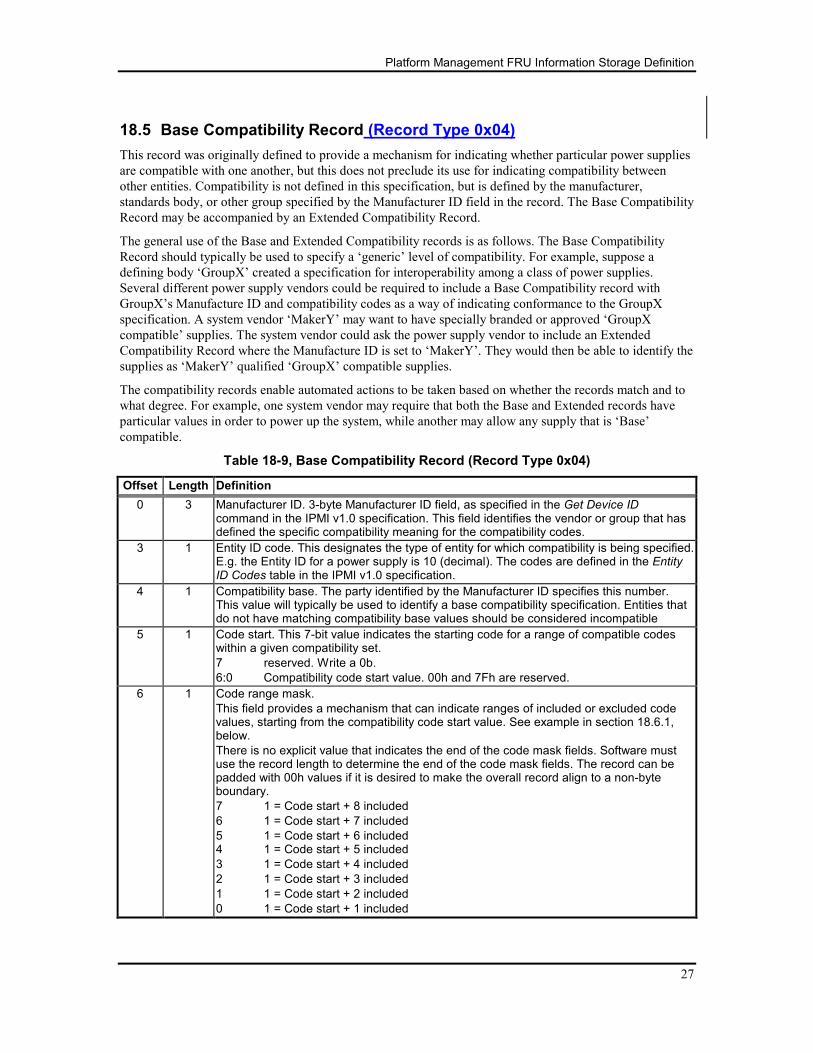
18.5 Base Compatibility Record (Record Type 0x04)
This record was originally defined to provide a mechanism for indicating whether particular power supplies
are compatible with one another, but this does not preclude its use for indicating compatibility between
other entities. Compatibility is not defined in this specification, but is defined by the manufacturer,
standards body, or other group specified by the Manufacturer ID field in the record. The Base Compatibility
Record may be accompanied by an Extended Compatibility Record.
The general use of the Base and Extended Compatibility records is as follows. The Base Compatibility
Record should typically be used to specify a ‘generic’ level of compatibility. For example, suppose a
defining body ‘GroupX’ created a specification for interoperability among a class of power supplies.
Several different power supply vendors could be required to include a Base Compatibility record with
GroupX’s Manufacture ID and compatibility codes as a way of indicating conformance to the GroupX
specification. A system vendor ‘MakerY’ may want to have specially branded or approved ‘GroupX
compatible’ supplies. The system vendor could ask the power supply vendor to include an Extended
Compatibility Record where the Manufacture ID is set to ‘MakerY’. They would then be able to identify the
supplies as ‘MakerY’ qualified ‘GroupX’ compatible supplies.
The compatibility records enable automated actions to be taken based on whether the records match and to
what degree. For example, one system vendor may require that both the Base and Extended records have
particular values in order to power up the system, while another may allow any supply that is ‘Base’
compatible.
Table 18-9, Base Compatibility Record (Record Type 0x04)
Offset Length Definition
0 3 Manufacturer ID. 3-byte Manufacturer ID field, as specified in the Get Device ID command in the IPMI v1.0 specification. This field identifies the vendor or group that has defined the specific compatibility meaning for the compatibility codes.
3 1 Entity ID code. This designates the type of entity for which compatibility is being specified. E.g. the Entity ID for a power supply is 10 (decimal). The codes are defined in the Entity ID Codes table in the IPMI v1.0 specification.
4 1 Compatibility base. The party identified by the Manufacturer ID specifies this number. This value will typically be used to identify a base compatibility specification. Entities that do not have matching compatibility base values should be considered incompatible
5 1 Code start. This 7-bit value indicates the starting code for a range of compatible codes within a given compatibility set.
7 reserved. Write a 0b.
6:0 Compatibility code start value. 00h and 7Fh are reserved.
6 1 Code range mask.
This field provides a mechanism that can indicate ranges of included or excluded code values, starting from the compatibility code start value. See example in section 18.6.1, below.
There is no explicit value that indicates the end of the code mask fields. Software must use the record length to determine the end of the code mask fields. The record can be padded with 00h values if it is desired to make the overall record align to a non-byte boundary.
7 1 = Code start + 8 included
6 1 = Code start + 7 included
5 1 = Code start + 6 included 4 1 = Code start + 5 included
3 1 = Code start + 4 included
2 1 = Code start + 3 included
1 1 = Code start + 2 included
0 1 = Code start + 1 included
Platform Management FRU Information Storage Definition
28
Offset Length Definition
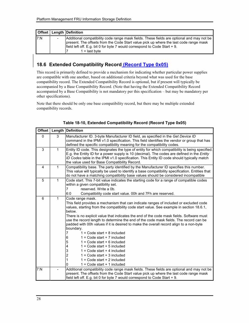
7:N - Additional compatibility code range mask fields. These fields are optional and may not be present. The offsets from the Code Start value pick up where the last code range mask field left off. E.g. bit 0 for byte 7 would correspond to Code Start + 9.
7 1 = last byte
18.6 Extended Compatibility Record (Record Type 0x05)
This record is primarily defined to provide a mechanism for indicating whether particular power supplies
are compatible with one another, based on additional criteria beyond what was used for the base
compatibility record. The Extended Compatibility Record is optional, but if present will typically be
accompanied by a Base Compatibility Record. (Note that having the Extended Compatibility Record
accompanied by a Base Compatibility is not mandatory per this specification – but may be mandatory per
other specifications).
Note that there should be only one base compatibility record, but there may be multiple extended
compatibility records.
Table 18-10, Extended Compatibility Record (Record Type 0x05)
Offset Length Definition
0 3 Manufacturer ID. 3-byte Manufacturer ID field, as specified in the Get Device ID command in the IPMI v1.0 specification. This field identifies the vendor or group that has defined the specific compatibility meaning for the compatibility codes.
3 1 Entity ID code. This designates the type of entity for which compatibility is being specified. E.g. the Entity ID for a power supply is 10 (decimal). The codes are defined in the Entity ID Codes table in the IPMI v1.0 specification. This Entity ID code should typically match the value used for Base Compatibility Record.
4 1 Compatibility base. The party identified by the Manufacturer ID specifies this number. This value will typically be used to identify a base compatibility specification. Entities that do not have a matching compatibility base values should be considered incompatible
5 1 Code start. This 7-bit value indicates the starting code for a range of compatible codes within a given compatibility set.
7 reserved. Write a 0b.
6:0 Compatibility code start value. 00h and 7Fh are reserved.
6 1 Code range mask.
This field provides a mechanism that can indicate ranges of included or excluded code values, starting from the compatibility code start value. See example in section 18.6.1, below.
There is no explicit value that indicates the end of the code mask fields. Software must use the record length to determine the end of the code mask fields. The record can be padded with 00h values if it is desired to make the overall record align to a non-byte boundary.
7 1 = Code start + 8 included
6 1 = Code start + 7 included
5 1 = Code start + 6 included 4 1 = Code start + 5 included
3 1 = Code start + 4 included
2 1 = Code start + 3 included
1 1 = Code start + 2 included
0 1 = Code start + 1 included
7:N - Additional compatibility code range mask fields. These fields are optional and may not be present. The offsets from the Code Start value pick up where the last code range mask field left off. E.g. bit 0 for byte 7 would correspond to Code Start + 9.
Platform Management FRU Information Storage Definition
29
18.6.1 Code Range Mask Fields Usage Example
The method of encoding the code ranges using bit masks was selected based on the observation that it is
unusual for long stretches of functional revisions to occur without compatibility being broken. It is also
based on the observation that it is not unusual to discover that all revisions are not equal, and that
sometimes a revision is backward compatible with some earlier revisions, but not all. The mechanism also
seeks to reduce the storage requirements for the compatibility records.
For this example, assume that the following code values are compatible: 10, 11, 12, 13, 14, 15, 16, 22, and
23. The Code Start value would be set to 10, and the first Code Range Mask would be set to 00111111b
which decodes as:
7 0 = Code start (10) + 8 (= code 18) not included
6 0 = Code start (10) + 7 (= code 17) not included
5 1 = Code start (10) + 6 (= code 16) included
4 1 = Code start (10) + 5 (= code 15) included
3 1 = Code start (10) + 4 (= code 14) included
2 1 = Code start (10) + 3 (= code 13) included
1 1 = Code start (10) + 2 (= code 12) included
0 1 = Code start (10) + 1 (= code 11) included
Note that this first byte only takes us up to code 18. A second byte is required to indicate compatibility with
codes 22 and 23. This byte is set to 00001000b, which decodes as:
7 0 = Code start (10) + 16 (= code 26) not included
6 0 = Code start (10) + 15 (= code 25) not included
5 0 = Code start (10) + 14 (= code 24) not included
4 1 = Code start (10) + 13 (= code 23) included
3 1 = Code start (10) + 12 (= code 22) included
2 0 = Code start (10) + 11 (= code 21) not included
1 0= Code start (10) + 10 (= code 20) not included
0 0 = Code start (10) + 9 (= code 19) not included
Thus, we find that using this method, we can encode up to 16 successive revisions using two bytes, while
also allowing random revisions among those 16 to be included or excluded from the set of compatible
codes.
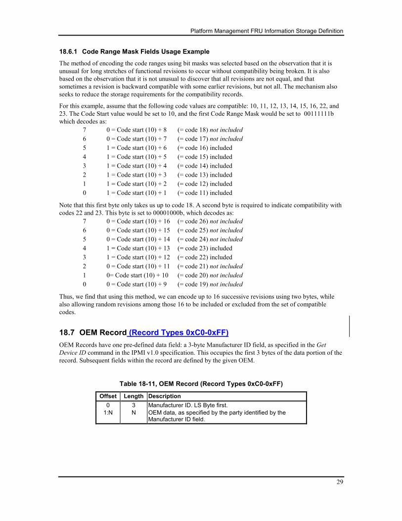
18.7 OEM Record (Record Types 0xC0-0xFF)
OEM Records have one pre-defined data field: a 3-byte Manufacturer ID field, as specified in the Get
Device ID command in the IPMI v1.0 specification. This occupies the first 3 bytes of the data portion of the
record. Subsequent fields within the record are defined by the given OEM.
Table 18-11, OEM Record (Record Types 0xC0-0xFF)
Offset Length Description
0 3 Manufacturer ID. LS Byte first.
1:N N OEM data, as specified by the party identified by the Manufacturer ID field.

Platform Management FRU Information Storage Definition
30
LAST PAGE