platform guide: 10000 series - f5 networks · platform guide: 10000 series. putting the unit in...
TRANSCRIPT
Platform Guide: 10000 Series
MAN-0408-07


Table of Contents
Legal Notices..............................................................................................................................7
Legal Notices.....................................................................................................................7
The 10000 Series Platform.........................................................................................................9
About 10000 Series models...............................................................................................9
About the platform..............................................................................................................9
Hardware included with the platform................................................................................10
Peripheral hardware requirements...................................................................................11
LCD panel........................................................................................................................11
About the LCD menus...........................................................................................11
Using the LCD panel.............................................................................................13
Indicator LEDs.................................................................................................................14
Status LED............................................................................................................14
Alarm LED.............................................................................................................15
Power supply LEDs...............................................................................................15
Indicator LED behavior..........................................................................................15
Defining custom alerts...........................................................................................15
Platform interfaces...........................................................................................................16
About managing interfaces....................................................................................16
About 40GbE QSFP+ interfaces...........................................................................19
Network interface LED behavior............................................................................21
Transceiver module specifications.........................................................................22
Cable pinout specifications....................................................................................22
Always-On Management..................................................................................................22
AOM Command Menu options..............................................................................22
Accessing the AOM Command Menu from the serial console..............................23
Configuring the management network..................................................................24
Accessing the AOM Command Menu using SSH.................................................24
About the host console capture buffer...................................................................25
Platform Installation.................................................................................................................27
About installing the platform.............................................................................................27
Determining which rack mounting kit to use.....................................................................27
About the front-mounting kit.............................................................................................27
Front-mounting kit hardware..................................................................................27
Installing using a front-mounting kit.......................................................................27
About the quick-install rail kit............................................................................................28
Installing the rail lock brackets.........................................................................................29
About grounding the platform...........................................................................................29
3
Table of Contents

Connecting the ground lug to the ground terminal................................................30
About powering the platform............................................................................................30
Connecting the cables and other hardware.....................................................................30
Configuring a management IP address using the LCD panel..........................................31
Licensing the platform......................................................................................................32
Platform Maintenance...............................................................................................................33
About maintaining the platform........................................................................................33
About AC power supplies.................................................................................................33
Installing an AC power supply...............................................................................34
About DC power supplies.................................................................................................34
Wiring the DC power supply terminal block...........................................................36
Installing a DC power supply.................................................................................37
About the fan tray.............................................................................................................38
Replacing the fan tray............................................................................................39
About the hard disk drives................................................................................................40
Identifying a faulty hard disk drive.........................................................................41
Replacing a hard disk drive tray............................................................................42
Environmental Guidelines........................................................................................................45
General environmental and installation guidelines...........................................................45
Guidelines for AC-powered equipment............................................................................46
Guidelines for DC-powered equipment............................................................................47
NEBS platform guidelines................................................................................................47
Platform airflow diagram..................................................................................................47
Platform Specifications............................................................................................................49
General specifications for system features......................................................................49
Platform hardware specifications - 10000 Series.............................................................49
Platform hardware specifications - 10150 Series.............................................................50
Platform environmental operating specifications..............................................................51
Platform power specifications - 10000s/10200v...............................................................51
Platform power specifications - 10050 Series..................................................................52
Platform power specifications - 10200v-SSL...................................................................53
Platform power specifications - 10150 Series..................................................................53
Safety requirements.........................................................................................................54
EMC requirements...........................................................................................................54
Acoustic, airflow, and altitude specifications....................................................................55
China RoHS Requirements......................................................................................................57
Hazardous substance levels for China.............................................................................57
Repackaging Guidelines..........................................................................................................59
4
Table of Contents

About repackaging the platform.......................................................................................59
Repackaging the platform................................................................................................59
Returned Material Data Security Statement...........................................................................61
About returned material data security..............................................................................61
About memory technologies used in F5 equipment.........................................................61
Volatile memory.....................................................................................................61
Battery-backed volatile memory............................................................................61
Non-volatile memory.............................................................................................61
About removing data from F5 components......................................................................62
Removing sensitive data from storage drives........................................................62
Removing IP address data from Always-On Management....................................63
Removing sensitive data from an internal hardware security module (HSM)........63
5
Table of Contents

6
Table of Contents

Legal Notices
Legal Notices
Publication Date
This document was published on April 5, 2016.
Publication Number
MAN-0408-07
Copyright
Copyright © 2016, F5 Networks, Inc. All rights reserved.
F5 Networks, Inc. (F5) believes the information it furnishes to be accurate and reliable. However, F5 assumesno responsibility for the use of this information, nor any infringement of patents or other rights of thirdparties which may result from its use. No license is granted by implication or otherwise under any patent,copyright, or other intellectual property right of F5 except as specifically described by applicable userlicenses. F5 reserves the right to change specifications at any time without notice.
Trademarks
AAM, Access Policy Manager, Advanced Client Authentication, Advanced Firewall Manager, AdvancedRouting, AFM, APM, Application Acceleration Manager, Application Security Manager, AskF5, ASM,BIG-IP, BIG-IP EDGE GATEWAY, iWorkflow, Cloud Extender, Cloud Manager, CloudFucious, ClusteredMultiprocessing, CMP, COHESION,DataManager, DDoS Frontline, DDoS SWAT,Defense.Net, defense.net[DESIGN], DevCentral, DevCentral [DESIGN], DNS Express, DSC, DSI, Edge Client, Edge Gateway,Edge Mobile, Edge Mobility, Edge Portal, ELEVATE, EM, ENGAGE, Enterprise Manager, F5, F5[DESIGN], F5 Agility, F5 Certified [DESIGN], F5 Networks, F5 SalesXchange [DESIGN], F5 Synthesis,f5 Synthesis, F5 Synthesis [DESIGN], F5 TechXchange [DESIGN], Fast Application Proxy, Fast Cache,FCINCO, Global Traffic Manager, GTM, GUARDIAN, iApps, IBR, iCall, iControl, iHealth, IntelligentBrowser Referencing, Intelligent Compression, IPv6 Gateway, iQuery, iRules, iRules OnDemand, iSession,L7 Rate Shaping, LC, Link Controller, LineRate, LineRate Point, LineRate Precision, LineRate Systems[DESIGN], Local Traffic Manager, LROS, LTM, Message Security Manager, MobileSafe, MSM,OneConnect, Packet Velocity, PEM, Policy EnforcementManager, Protocol SecurityManager, PSM, ReadyDefense, Real Traffic Policy Builder, SalesXchange, ScaleN, SDAS (except in Japan), SDC, SignallingDelivery Controller, Solutions for an application world, Software Designed Application Services, Silverline,SSLAcceleration, SSL Everywhere, StrongBox, SuperVIP, SYNCheck, SYNTHESIS, TCP Express, TDR,TechXchange, TMOS, TotALL, TDR, TMOS, Traffic Management Operating System, Traffix, Traffix[DESIGN], Transparent Data Reduction, UNITY, VAULT, vCMP, VE F5 [DESIGN], Versafe, Versafe[DESIGN], VIPRION, Virtual Clustered Multiprocessing, WebSafe, and ZoneRunner, are trademarks orservice marks of F5 Networks, Inc., in the U.S. and other countries, and may not be used without F5'sexpress written consent.
All other product and company names herein may be trademarks of their respective owners.
Export Regulation Notice
This product may include cryptographic software. Under the Export Administration Act, the United Statesgovernment may consider it a criminal offense to export this product from the United States.
RF Interference Warning
This is a Class A product. In a domestic environment this product may cause radio interference, in whichcase the user may be required to take adequate measures.
FCC Compliance
This equipment has been tested and found to comply with the limits for a Class A digital device pursuantto Part 15 of FCC rules. These limits are designed to provide reasonable protection against harmfulinterference when the equipment is operated in a commercial environment. This unit generates, uses, andcan radiate radio frequency energy and, if not installed and used in accordance with the instruction manual,may cause harmful interference to radio communications. Operation of this equipment in a residential areais likely to cause harmful interference, in which case the user, at his own expense, will be required to takewhatever measures may be required to correct the interference.
Anymodifications to this device, unless expressly approved by themanufacturer, can void the user's authorityto operate this equipment under part 15 of the FCC rules.
Canadian Regulatory Compliance
This Class A digital apparatus complies with Canadian ICES-003.
Standards Compliance
This product conforms to the IEC, European Union, ANSI/UL and Canadian CSA standards applicable toInformation Technology products at the time of manufacture.
VCCI Class A Compliance
This is a Class A product. In a domestic environment, this product may cause radio interference, in whichcase the user may be required to take corrective actions. VCCI-A
8
Legal Notices
The 10000 Series Platform
About 10000 Series models
The BIG-IP® 10000 Series platform is a powerful system that is capable of managing traffic for any size ofenterprise. This platform series includes models that support either hard disk drives (HDDs) or solid-statedrives (SSDs).
F5 offers three performance levels of SSL offload in the 10000 Series: the 10000s, 10200v, and 10200v-SSL.The 10200v-SSL platform features high-performance SSL hardware that frees servers from the task ofencrypting and decrypting data.
The 10000 Series platform is available with a FIPS-certified hardware security module (HSM) as afactory-installed option (10200v-FIPS and 10350v-FIPS). The 10150 Series platform is available in NetworkEquipment-Building System (NEBS) compliant versions (10150s-NEBS and 10350v-NEBS).
Note: FIPS is not supported in vCMP guests.
Please see the data sheet at https://f5.com/products/platforms for more information.
About the platform
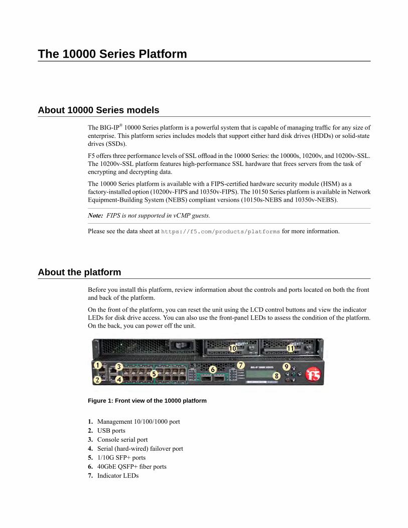
Before you install this platform, review information about the controls and ports located on both the frontand back of the platform.
On the front of the platform, you can reset the unit using the LCD control buttons and view the indicatorLEDs for disk drive access. You can also use the front-panel LEDs to assess the condition of the platform.On the back, you can power off the unit.
Figure 1: Front view of the 10000 platform
1. Management 10/100/1000 port2. USB ports3. Console serial port4. Serial (hard-wired) failover port5. 1/10G SFP+ ports6. 40GbE QSFP+ fiber ports7. Indicator LEDs

8. LCD display9. LCD control buttons10. Disk drive bay 111. Disk drive bay 2
The back of the platform includes two AC power supplies and the fan tray.
Figure 2: Back view of the platform
1. Power input panel 12. Power input panel 23. Fan tray4. Chassis ground lugs
Hardware included with the platform
This platform should include all of the hardware components listed here.
HardwareQuantity
Power cables (black), AC power only
Note: The power cables included with this unit are for exclusive use with this unit andshould not be used with other electrical appliances.
2
DC terminal block plug, DC power option only2
RJ45 to RJ45 failover cable, CAT 5 crossover (blue)1
RJ45 to DB9 console port cable (beige)1
RJ45F to RJ45M rolled adapter (beige)1
Quick-install rail kit (left and right rails)1
Rail lock brackets with captive screw (left and right)2
Front-mounting kit (left and right brackets)1
Front bezel1
SFP+ transceiver modules2
10
The 10000 Series Platform

Peripheral hardware requirements
For each platform, you might need to provide additional peripheral hardware. If you plan to remotelyadminister the system, it would be helpful to have a workstation already connected to the same subnet asthe management interface.
DescriptionType of hardware
Youmust provide networking devices that are compatible with the networkinterface cards that are installed in the platform. You can use either10/100/1000/10000-Gigabit or 40-Gigabit Ethernet switches.
Network hubs, switches, orconnectors to connect to theplatform network interfaces
You can use any USB-certified CD/DVD mass storage device or a USBflash drive for installing upgrades and for system recovery.
Note: External CD/DVD drives must be externally powered.
External USBCD/DVDdriveor USB flash drive
You can remotely manage the platform by connecting to a serial consoleterminal server through the console port.
Important: In the event that network access is impaired or not yetconfigured, the serial console might be the only way to access the unit. You
Serial console
should perform all installations and upgrades using the serial console, asthese procedures require reboots, in which network connectivity is losttemporarily.
You can use the default platform configuration if you have a managementworkstation set up.
Management workstation onthe same IP network as theplatform
LCD panel
The LCD panel provides the ability to manage the unit without attaching a console or network cable.
Figure 3: The LCD panel and control buttons
About the LCD menus
There are three menus on the LCD panel. You can configure the display options to meet your needs.
11
Platform Guide: 10000 Series
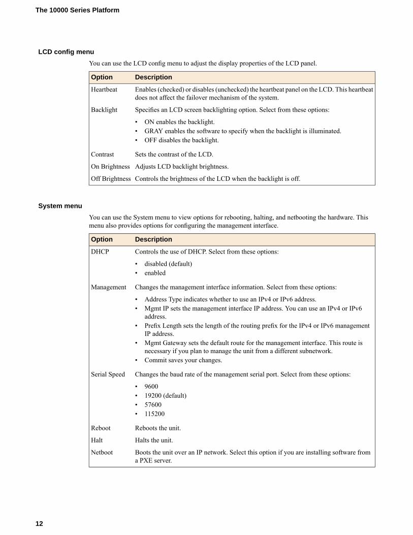
LCD config menu
You can use the LCD config menu to adjust the display properties of the LCD panel.
DescriptionOption
Enables (checked) or disables (unchecked) the heartbeat panel on the LCD. This heartbeatdoes not affect the failover mechanism of the system.
Heartbeat
Specifies an LCD screen backlighting option. Select from these options:Backlight
• ON enables the backlight.• GRAY enables the software to specify when the backlight is illuminated.• OFF disables the backlight.
Sets the contrast of the LCD.Contrast
Adjusts LCD backlight brightness.On Brightness
Controls the brightness of the LCD when the backlight is off.Off Brightness
System menu
You can use the System menu to view options for rebooting, halting, and netbooting the hardware. Thismenu also provides options for configuring the management interface.
DescriptionOption
Controls the use of DHCP. Select from these options:DHCP
• disabled (default)• enabled
Changes the management interface information. Select from these options:Management
• Address Type indicates whether to use an IPv4 or IPv6 address.• Mgmt IP sets the management interface IP address. You can use an IPv4 or IPv6
address.• Prefix Length sets the length of the routing prefix for the IPv4 or IPv6 management
IP address.• Mgmt Gateway sets the default route for the management interface. This route is
necessary if you plan to manage the unit from a different subnetwork.• Commit saves your changes.
Changes the baud rate of the management serial port. Select from these options:Serial Speed
• 9600• 19200 (default)• 57600• 115200
Reboots the unit.Reboot
Halts the unit.Halt
Boots the unit over an IP network. Select this option if you are installing software froma PXE server.
Netboot
12
The 10000 Series Platform

Screens menu
You can use the Screens menu to specify the information that is displayed on the default screens.
DescriptionOption
Displays the date and time.DateScreen
Displays the information screen.InfoScreen
Displays the RAID status screen.
Note: Not available on solid-state drive (SSD) platforms.
RaidScreen
Displays product version information.VersionScreen
Using the LCD panel
Put the LCD panel into Menu mode to manage the platform using the LCD menus and control buttons.
Press the X button to activate Menu mode for the LCD.The Left Arrow, Right Arrow, Up Arrow, and Down Arrow buttons are functional only when the LCDis in Menu mode.
Pausing on a screen
Normally, the screens cycle on the LCD panel at a constant rate, but you can pause on a specific screen.
Push the Check button to toggle the LCD screen between Hold and Rotate modes.In Hold mode, a single screen is displayed. The Rotate mode changes the screen displayed on the LCDevery four seconds.
Powering on the unit
Use the LCD control buttons to power on the unit.
Press the Check button to power on a unit that is shut down.
Halting the unit
Use the LCD control buttons to halt the unit. You should halt the unit before you power it down or rebootit using the LCD menu options.
1. Press the X button, then use the arrow keys to navigate to the System menu.2. Press the Check button.3. Navigate to the Halt menu.4. Press the Check button.5. Press the Check button again at the confirmation screen.
Wait 60 seconds before powering the machine off or rebooting it.
13
Platform Guide: 10000 Series

Putting the unit in standby mode
Use the LCD control buttons to put the unit into standby mode.
Hold the X button for four seconds to put the unit in standby mode and power off the host subsystem.F5® recommends that you halt the system before you power off the system in this manner.
Resetting the unit
Use the LCD control buttons to reset the unit.
Hold the Check button for four seconds to reset the unit.You should only use this option after you halt the unit.
Clearing alerts
Use the LCD control buttons to clear alerts from the LCD screen.
Press the Check button to clear any alerts on the LCD screen.You must clear any alerts on the screen before you can use the LCD panel.
Indicator LEDs
The behavior of each LED indicates the status of the system.
Status LED
The status LED indicate the operating state of the system.
DescriptionState
System is halted and powered down.off/none
System is running in normal mode. Also indicates that the system is in an Active stateof a device group.
green solid
System is running in an impaired mode. The condition is not considered to besignificant enough to be considered an alarm condition. Also indicates that the systemis the Standby member of a device group.
yellow solid
The system is not under host computer control. This might be due to the host beinghalted or in EUD mode, or due to a software or hardware problem that interferes withthe host's control of the LED.
yellow blinking(with traffic)
14
The 10000 Series Platform

Alarm LED
The alarm LED indicate system alarm conditions and the severity of the alarm condition.
There are five levels of messages.
Note: The alarm LED might continue to display until alerts are cleared using the LCD panel.
DescriptionState
Informational or no alarm conditions present. System is operating properly.off/none
Warning (0). System may not be operating properly, but the condition is not severeor potentially damaging.
yellow solid
Error (1). System is not operating properly, but the condition is not severe or potentiallydamaging.
yellow blinking
Alert (2) or Critical (3). System is not operating properly, and the condition ispotentially damaging.
red solid
Emergency (4). System is not operating, and the condition is potentially damaging.red blinking
Power supply LEDs
The power supply LEDs indicate the operating state of the power supplies.
DescriptionPower 2 statePower 1 state
Power supply is present and operating properly. Also indicates whenthe system in is power standby mode.
green solidgreen solid
Power supply is present, but not operating properly.yellow solidyellow solid
No power supply present.off/noneoff/none
Indicator LED behavior
The indicator LEDs behave in a specific manner to indicate system or component status.
DescriptionBehavior
LED is not lit and does not display any color.off (none)
LED is lit and does not blink.solid
LED turns on and off at a regular frequency.blinking
LED turns on and off with an irregular frequency and might sometimes appear solid.intermittent
Defining custom alerts
The /etc/alertd/alert.conf and the /config/user_alert.conf files on the BIG-IP® systemdefine alerts that cause the indicators to change. The /etc/alertd/alert.conf file defines standardsystem alerts, and the /config/user_alert.conf file defines custom settings. You should edit only the/config/user_alert.conf file.
15
Platform Guide: 10000 Series

1. Open a command prompt on the system.2. Change to the /config directory.
cd /config
3. Using a text editor, such as vi or Pico, open the /config/user_alert.conf file.4. Edit the file, as needed.
For example, add these lines to the end of the file to create a custom alert in which the front panel LEDsindicate when a node is down:
alert BIGIP_MCPD_MCPDERR_POOL_MEMBER_MON_DOWN "Pool member (.*?):(.*?) monitorstatus down."{snmptrap OID=".1.3.6.1.4.1.3375.2.4.0.10";lcdwarn description="Node down" priority="1"
}alert BIGIP_MCPD_MCPDERR_NODE_ADDRESS_MON_DOWN "Node (.*?) monitor statusdown." {snmptrap OID=".1.3.6.1.4.1.3375.2.4.0.12";lcdwarn description="Node address down" priority="1"
}alert BIGIP_MCPD_MCPDERR_POOL_MEMBER_MON_UP "Pool member (.*?):(.*?) monitorstatus up."{snmptrap OID=".1.3.6.1.4.1.3375.2.4.0.11"
}alert BIGIP_MCPD_MCPDERR_NODE_ADDRESS_MON_UP "Node (.*?) monitor status up."
{snmptrap OID=".1.3.6.1.4.1.3375.2.4.0.13"
}
5. Save the file and exit the text editor.
Platform interfaces
Every platform includes multiple interfaces. The exact number of interfaces that are on the system dependson the platform type.
Each interface on the platform has a set of properties that you can configure, such as enabling or disablingthe interface, setting the requested media type and duplex mode, and configuring flow control.
About managing interfaces
You can use the Traffic Management Shell (tmsh) or the BIG-IP® Configuration utility to manage platforminterfaces.
Viewing the status of a specific interface using tmsh
You can use tmsh to view the status of a specific interface on a platform.
1. Open the Traffic Management Shell (tmsh).tmsh
16
The 10000 Series Platform

2. Change to the network module.net
The system prompt updates with themodule name: user@bigip01(Active)(/Common)(tmos.net)#3. Display the current status of a specific interface.
show interface <interface_key>This is an example of the output that you might see when you run this command on interface 1.1:
-------------------------------------------------------------Net::InterfaceName Status Bits Bits Pkts Pkts Drops Errs Media
In Out In Out-------------------------------------------------------------1.1 up 5.9T 0 7.3G 0 7.3G 0 10000SR-FD
Viewing the status of all interfaces using tmsh
You can use tmsh to view the status of all interfaces on the platform.
1. Open the Traffic Management Shell (tmsh).tmsh
2. Change to the network module.net
The system prompt updates with themodule name: user@bigip01(Active)(/Common)(tmos.net)#3. Display the current status of all interfaces.
show interfaceThis is an example of the output that you might see when you run this command:
----------------------------------------------------------------Net::InterfaceName Status Bits Bits Pkts Pkts Drops Errs Media
In Out In Out----------------------------------------------------------------1.1 up 5.9T 0 7.3G 0 7.3G 0 10000SR-FD1.2 miss 0 0 0 0 0 0 none1.3 miss 0 0 0 0 0 0 none1.4 miss 0 0 0 0 0 0 none1.5 miss 0 0 0 0 0 0 none1.6 miss 0 0 0 0 0 0 none1.7 miss 0 0 0 0 0 0 none1.8 miss 0 0 0 0 0 0 none1.9 miss 0 0 0 0 0 0 none1.10 miss 0 0 0 0 0 0 none1.11 miss 0 0 0 0 0 0 none1.12 miss 0 0 0 0 0 0 none1.13 miss 0 0 0 0 0 0 none1.14 miss 0 0 0 0 0 0 none1.15 miss 0 0 0 0 0 0 none1.16 miss 0 0 0 0 0 0 none1.17 uninit 0 0 0 0 0 0 none1.18 uninit 0 0 0 0 0 0 none1.19 uninit 0 0 0 0 0 0 none1.20 uninit 0 0 0 0 0 0 none1.21 uninit 0 0 0 0 0 0 none1.22 uninit 0 0 0 0 0 0 none1.23 uninit 0 0 0 0 0 0 none1.24 uninit 0 0 0 0 0 0 none
17
Platform Guide: 10000 Series
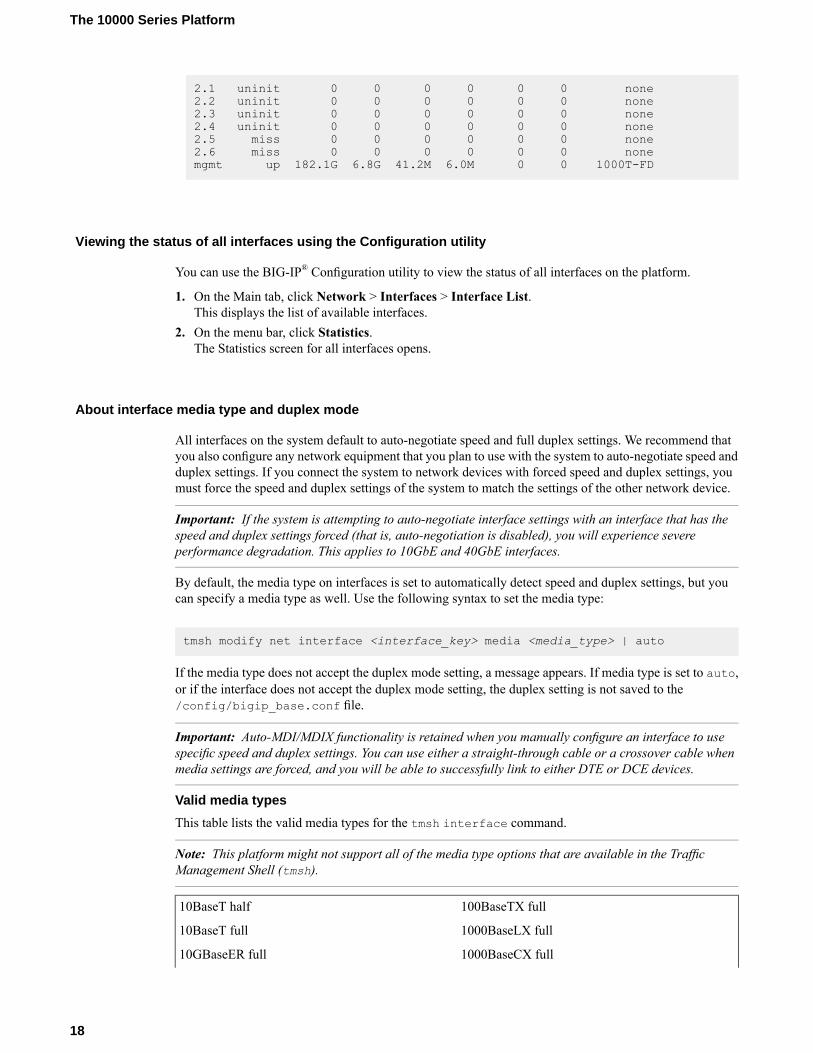
2.1 uninit 0 0 0 0 0 0 none2.2 uninit 0 0 0 0 0 0 none2.3 uninit 0 0 0 0 0 0 none2.4 uninit 0 0 0 0 0 0 none2.5 miss 0 0 0 0 0 0 none2.6 miss 0 0 0 0 0 0 nonemgmt up 182.1G 6.8G 41.2M 6.0M 0 0 1000T-FD
Viewing the status of all interfaces using the Configuration utility
You can use the BIG-IP® Configuration utility to view the status of all interfaces on the platform.
1. On the Main tab, click Network > Interfaces > Interface List.This displays the list of available interfaces.
2. On the menu bar, click Statistics.The Statistics screen for all interfaces opens.
About interface media type and duplex mode
All interfaces on the system default to auto-negotiate speed and full duplex settings. We recommend thatyou also configure any network equipment that you plan to use with the system to auto-negotiate speed andduplex settings. If you connect the system to network devices with forced speed and duplex settings, youmust force the speed and duplex settings of the system to match the settings of the other network device.
Important: If the system is attempting to auto-negotiate interface settings with an interface that has thespeed and duplex settings forced (that is, auto-negotiation is disabled), you will experience severeperformance degradation. This applies to 10GbE and 40GbE interfaces.
By default, the media type on interfaces is set to automatically detect speed and duplex settings, but youcan specify a media type as well. Use the following syntax to set the media type:
tmsh modify net interface <interface_key> media <media_type> | auto
If the media type does not accept the duplex mode setting, a message appears. If media type is set to auto,or if the interface does not accept the duplex mode setting, the duplex setting is not saved to the/config/bigip_base.conf file.
Important: Auto-MDI/MDIX functionality is retained when you manually configure an interface to usespecific speed and duplex settings. You can use either a straight-through cable or a crossover cable whenmedia settings are forced, and you will be able to successfully link to either DTE or DCE devices.
Valid media types
This table lists the valid media types for the tmsh interface command.
Note: This platform might not support all of the media type options that are available in the TrafficManagement Shell (tmsh).
100BaseTX full10BaseT half
1000BaseLX full10BaseT full
1000BaseCX full10GBaseER full
18
The 10000 Series Platform
1000BaseT half10GBaseLR full
1000BaseT full10GBaseSR full
1000BaseSX full10GBaseT full
auto10SFP+Cu full
none40GBaseSR4 full
no-phy40GBaseLR4 full
100BaseTX half
Viewing valid media types for an interface
You can use tmsh to view the valid media types for an interface.
Note: This platform might not support all of the media type options that are available in tmsh.
1. Open the Traffic Management Shell (tmsh).tmsh
2. Change to the network module.net
The system prompt updates with themodule name: user@bigip01(Active)(/Common)(tmos.net)#3. Display the valid media types for a specific interface.
list interface <interface_key> media-capabilities
Important: In all Gigabit Ethernet modes, the only valid duplex mode is full duplex.
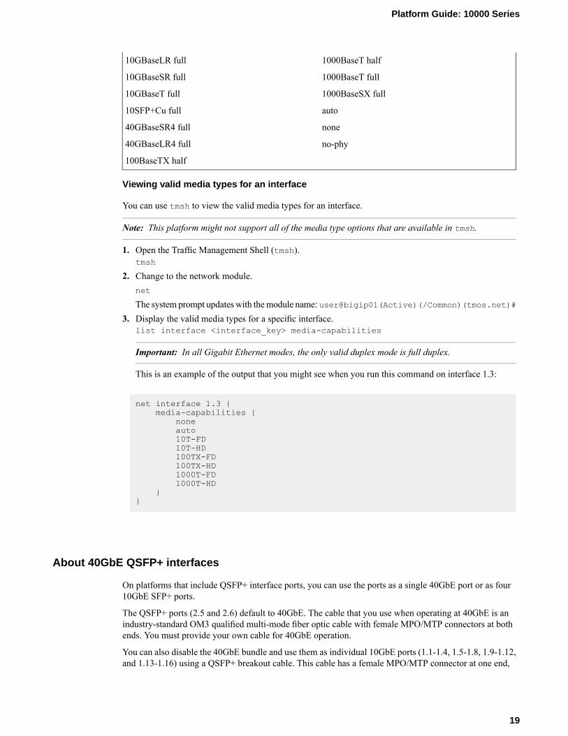
This is an example of the output that you might see when you run this command on interface 1.3:
net interface 1.3 {media-capabilities {
noneauto10T-FD10T-HD100TX-FD100TX-HD1000T-FD1000T-HD
}}
About 40GbE QSFP+ interfaces
On platforms that include QSFP+ interface ports, you can use the ports as a single 40GbE port or as four10GbE SFP+ ports.
The QSFP+ ports (2.5 and 2.6) default to 40GbE. The cable that you use when operating at 40GbE is anindustry-standard OM3 qualified multi-mode fiber optic cable with female MPO/MTP connectors at bothends. You must provide your own cable for 40GbE operation.
You can also disable the 40GbE bundle and use them as individual 10GbE ports (1.1-1.4, 1.5-1.8, 1.9-1.12,and 1.13-1.16) using a QSFP+ breakout cable. This cable has a female MPO/MTP connector at one end,
19
Platform Guide: 10000 Series

which connects to the QSFP+ port, and four LC duplex connectors at the other end, which connect to SFP+modules on an upstream switch.
Note: If you are using a breakout cable for 10GbE connectivity, you should use the supported distance asdetailed in the Specifications for fiber QSFP+ modules section of this platform guide and not theSpecifications for fiber SFP+ modules section.
Figure 4: An example of a QSFP+ breakout cable
You can order these QSFP+ components from F5® Networks:
• QSFP+ breakout cables (MTP to LC), provided as a pair, in these lengths:
• 1 meter (F5-UPG-QSFP+-1M-2)• 3 meter (F5-UPG-QSFP+-3M-2+)• 10 meter (F5-UPG-QSFP+-10M-2)
• F5-branded 40GbE QSFP+ transceiver modules (F5-UPG-QSFP+)
Configuring bundling for 40GbE QSFP+ interfaces using tmsh
You can use tmsh to configure bundling for the 40GbE QSFP+ interfaces on a platform. When you disablebundling, you can use the 40GbE ports as individual 10GbE ports.
1. Open the Traffic Management Shell (tmsh).tmsh
2. Change to the network module.net
The system prompt updates with themodule name: user@bigip01(Active)(/Common)(tmos.net)#3. Configure bundling for a specific interface, where <interface_key> is 2.1, 2.2, 2.3, or 2.4.
modify interface <interface_key> bundle [enabled | disabled]
Note: When a 2.x port is bundled, the LEDs for the 10GbE ports remain OFF. When a 2.x port isunbundled, the 40GbE LEDs remain OFF.
Configuring bundling for 40GbE QSFP+ interfaces using the Configuration utility
You can use the BIG-IP® Configuration utility to configure bundling for the 40GbE QSFP+ interfaces ona platform. When you disable bundling, you can use the 40GbE ports as individual 10GbE ports.
20
The 10000 Series Platform
1. On the Main tab, click Network > Interfaces > Interface List.This displays the list of available interfaces.
2. Click an interface name.The properties screen for that interface opens.
3. For the Bundled setting, select whether to enable or disable bundling.4. Click Update.
Network interface LED behavior
The appearance and behavior of the network interface LEDs on the platform indicate network traffic activity,interface speed, and interface duplexity.
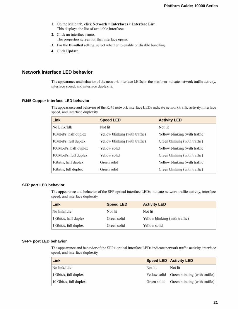
RJ45 Copper interface LED behavior
The appearance and behavior of the RJ45 network interface LEDs indicate network traffic activity, interfacespeed, and interface duplexity.
Activity LEDSpeed LEDLink
Not litNot litNo Link/Idle
Yellow blinking (with traffic)Yellow blinking (with traffic)10Mbit/s, half duplex
Green blinking (with traffic)Yellow blinking (with traffic)10Mbit/s, full duplex
Yellow blinking (with traffic)Yellow solid100Mbit/s, half duplex
Green blinking (with traffic)Yellow solid100Mbit/s, full duplex
Yellow blinking (with traffic)Green solid1Gbit/s, half duplex
Green blinking (with traffic)Green solid1Gbit/s, full duplex
SFP port LED behavior
The appearance and behavior of the SFP optical interface LEDs indicate network traffic activity, interfacespeed, and interface duplexity.
Activity LEDSpeed LEDLink
Not litNot litNo link/Idle
Yellow blinking (with traffic)Green solid1 Gbit/s, half duplex
Yellow solidGreen solid1 Gbit/s, full duplex
SFP+ port LED behavior
The appearance and behavior of the SFP+ optical interface LEDs indicate network traffic activity, interfacespeed, and interface duplexity.
Activity LEDSpeed LEDLink
Not litNot litNo link/Idle
Green blinking (with traffic)Yellow solid1 Gbit/s, full duplex
Green blinking (with traffic)Green solid10 Gbit/s, full duplex
21
Platform Guide: 10000 Series
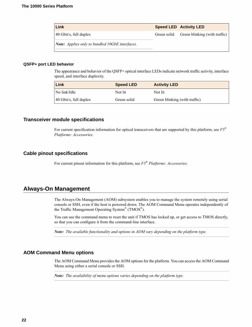
Activity LEDSpeed LEDLink
Green blinking (with traffic)Green solid40 Gbit/s, full duplex
Note: Applies only to bundled 10GbE interfaces.
QSFP+ port LED behavior
The appearance and behavior of the QSFP+ optical interface LEDs indicate network traffic activity, interfacespeed, and interface duplexity.
Activity LEDSpeed LEDLink
Not litNot litNo link/Idle
Green blinking (with traffic)Green solid40 Gbit/s, full duplex
Transceiver module specifications
For current specification information for optical transceivers that are supported by this platform, see F5®
Platforms: Accessories.
Cable pinout specifications
For current pinout information for this platform, see F5® Platforms: Accessories.
Always-On Management
The Always-On Management (AOM) subsystem enables you to manage the system remotely using serialconsole or SSH, even if the host is powered down. The AOM Command Menu operates independently ofthe Traffic Management Operating System® (TMOS®).
You can use the command menu to reset the unit if TMOS has locked up, or get access to TMOS directly,so that you can configure it from the command-line interface.
Note: The available functionality and options in AOM vary depending on the platform type.
AOM Command Menu options
TheAOMCommandMenu provides the AOMoptions for the platform. You can access the AOMCommandMenu using either a serial console or SSH.
Note: The availability of menu options varies depending on the platform type.
22
The 10000 Series Platform

DescriptionOptionLetter
Configures the baud speed for connecting to AOM using the serialconsole. Select from these options:
Set console baud rateB
• 9600• 19200 (default)• 38400• 57600• 115200
Displays information about the AOMfirmware and bootloader, chassisserial and part numbers, blade serial number, MAC address, and powerstatus for the active console.
Display platforminformation
I
Powers the host subsystem on or off.Power on/off hostsubsystem
P
Resets the host subsystem with a hardware reset.
Important: F5® does not recommend using this option under typicalcircumstances. It does not allow for graceful shutdown of the system.
Reset host subsystemR
Runs the AOM network configuration utility. This utility enables youto reconfigure the IP address, netmask, and default gateway used by
Configure AOM networkN
AOM. If you use this option while connected using SSH, your sessionwill be disconnected as a part of the network configuration operation.
Note: This option is not available when you are connected using SSH.
Sets a session idle timeout (in seconds) for the AOM SSH server.Available values are 0 (no timeout; default value), or between 30 and86400 (one day).
Configure SSH ServerS
Resets the AOM subsystem. In this case, the system is reset with ahardware reset.
Important: We do not recommend using this option under normalcircumstances. It does not allow for graceful shutdown of the system.
Reset AOMA
Buffers the last 4K bytes of console output from the host and saves itto a non-volatile storage location.
Important: This option is hidden and disabled by default. It is intendedto be used as a diagnostic tool by F5 Support. When this option isenabled, then disabled, the buffer is cleared.
Host Console CaptureBuffer
H
Displays a list of latched events/errors or out-of-range sensors.Display error reportE
Exits the AOM Command Menu and returns to terminal emulationmode.
Quit menu and return toconsole
Q
Accessing the AOM Command Menu from the serial console
You can access the AOM Command Menu using the front panel serial console.
23
Platform Guide: 10000 Series

1. Connect to the system using the serial console.2. Open the AOM Command Menu.
Esc (
Configuring the management network
You can assign a management IP address, netmask, and gateway to access AOM either manually or withDHCP.
1. Connect to the system using the serial console.2. Open the AOM Command Menu.
Esc (
3. Type n to open the AOM management network configurator.4. Assign a management IP address, netmask, and gateway:
• To use DHCP to assign the addresses, type y when prompted about using DHCP.• To manually assign the addresses, type n when prompted about using DHCP. At the prompts, type
values for IP address (required), netmask (required), and gateway (optional).
A confirmation message displays the configured management IP address, netmask, and gateway.5. (Optional) Type i to verify the assigned addresses.
Accessing the AOM Command Menu using SSH
Before you access the AOM Command Menu using SSH, you must assign a management IP address,netmask, and gateway for AOM. You can assign the addresses manually or with DHCP.
You can access the AOM Command Menu remotely using SSH from a management workstation that isconnected to the same subnet as the platform's management (MGMT) interface.
Note: On this platform, AOM allows only one SSH connection at a time.
1. Open an SSH session, where <ip addr> is the IP address that you configured for AOM.ssh root@<ip addr>
2. Type the root password.3. Open the AOM Command Menu.
Esc (
Setting an SSH idle session timeout
You can specify a timeout value (in seconds) for idle AOM SSH sessions. You can access the AOMCommand Menu using either a serial console or SSH.
1. Connect to the system using the serial console.2. Open the AOM Command Menu.
Esc (
3. Type s to configure a timeout value for idle SSH sessions.4. Type a timeout value.
24
The 10000 Series Platform

The default value is 0 (no timeout). Available values are 0, or between 30 and 86400 (one day).
Disabling network configuration
You can connect to the system's serial console to disable SSH access to AOM over the network. This doesnot affect console access to AOM.
1. Connect to the system using the serial console.2. Open the AOM Command Menu.
Esc (
3. Type n to open the AOM management network configurator.4. Type n when prompted about using DHCP.5. Type 0.0.0.0 at the IP address prompt.
A confirmation message displays the configured management IP address, netmask, and gateway.6. (Optional) Type i to verify that network configuration is disabled.
About the host console capture buffer
When enabled, the host console capture buffer (H) option in the AOM Command Menu buffers the last 4Kbytes of console output from the host and saves it to a non-volatile storage location.
Important: This option is intended to be used as a diagnostic tool by F5® Technical Support.
Enabling the host console capture buffer
1. Connect to the system using the serial console or by opening an SSH session to the AOM managementIP address.
2. Open the AOM Command Menu.Esc (
3. Enable the host console capture buffer (H) option.Esc h
4. When prompted to confirm, type y.This message displays: Host console capture buffer enabled.
The host console capture buffer (H) option now displays in the AOM Command Menu.
Showing the host console capture buffer
1. Connect to the system using the serial console or by opening an SSH session to the AOM managementIP address.
2. Open the AOM Command Menu.Esc (
3. Type h to select the host console capture buffer option.This message displays: The host console capture buffer is actively capturing.
4. Type s to show the contents of the buffer.
25
Platform Guide: 10000 Series

Disabling the host console capture buffer
When you no longer require use of the host console capture buffer, you can disable it.
1. Connect to the system using the serial console or by opening an SSH session to the AOM managementIP address.
2. Open the AOM Command Menu.Esc (
3. Type h to select the host console capture buffer option.This message displays: The host console capture buffer is actively capturing.
4. Type d to disable the host console capture buffer.5. When prompted to confirm, type y.
This message displays: Host console capture buffer disabled.
The buffer is cleared, and the host console capture buffer (H) option no longer displays in the AOMCommand Menu.
26
The 10000 Series Platform
Platform Installation
About installing the platform
After you have reviewed the hardware requirements and become familiar with the 10000 Series platform,you can install the unit.
Important: Before you install this platform, review the environmental guidelines to make sure that you areinstalling and using the platform into a compatible rack and in the appropriate environment.
Determining which rack mounting kit to use
The 10000 Series platform comes with two types of rack mounting kits: sliding quick-install rail-mountingand stationary front-mounting. An advantage of installing the quick-install kit is that you can then slide theunit in and out of the rack as needed.
The tasks required to install the platform might differ depending on the type of rack mount you decide touse or which type of cabinet unit you are installing into (single two-post cabinet or four-post cabinet).
About the front-mounting kit
You can use the front-mounting kit if you are installing into a two-post rack.
Note: You should use the front-mounting kit to install the platform only if you are installing into a two-postrack. For installing the platform into all other types of racks or cabinets, you should use the quick-installrail kit.
Front-mounting kit hardware
The front-mounting kit includes these hardware parts.
HardwareQuantity
Front-mounting brackets2
M4 x 10mm flat head screws6
Installing using a front-mounting kit
This platform includes front-mounting brackets, which you can use to attach the unit directly to the rack.

1. Align the bracket's keyhole slots with the PEM (brand) fasteners on the side of the unit.2. Slide the bracket toward the front of the unit to lock the bracket into place.
Important: You must secure the bracket to the unit using three of the flat head screws provided withthe platform.
3. Repeat steps 1 and 2 for the other bracket.4. Secure the front-mounting brackets to the rack using four rack manufacturer-provided screws (two per
side).The unit must be securely fastened to the rack to provide adequate stability and to prevent the unit fromfalling out of the rack.
5. Attach the front bezel to the unit by grasping the bezel on either side using the indentations provided.
Note: Failure to use the indentations could result in pinched fingers.
If the rack you have does not provide adequate support for the unit, youmight need a shelf kit. F5 recommendsusing a shelf kit created by the rack manufacturer, if available.
About the quick-install rail kit
Use the quick-install rail kit if you want to be able to slide the unit in or out of the rack for maintenanceactivities. The kit includes two rails (left and right) and eight #8-32 thumb screws. The rails snap into placein the rack, and no tools are required to install a platform using this kit.
The rails are optimized for installation into square hole cabinets, but they can be installed in other cabinetstyles, such as round hole cabinets, using the screws provided. The rails are easily converted to mount toeither cabinet style.
Figure 5: Quick-install rail kit
28
Platform Installation

For information about installing the platform using the quick-install rail kit, see the instruction guide providedby the manufacturer, which is included with the kit hardware.
After installing the platform, secure it to the rack with the rail lock brackets that are provided. Attach thefront bezel to the unit by grasping the bezel using the indentations located on either side.
Installing the rail lock brackets
The rail lock brackets help secure a quick-install, rail kit-mounted platform to a rack.
1. Attach the rail lock brackets to each side of the unit using the M4 flat head screws that are included inthe kit.
2. Slide the unit into the rack, and then secure the rail lock brackets to the rack on each side of the unitusing the #8-32 captive thumb screws on the bracket.Use 18 to 20 inch-pounds (2.0 to 2.3 Newton-meters) of torque on these screws.
About grounding the platform
You should ground the platform after you install it in a rack. The chassis ground lug is located on the backof the platform.
Do not secure multiple bonding or grounding connectors with the same bolt. The grounding connectors donot need to be removed to perform service or installation procedures. You can connect other bonding orgrounding conductors to a grounding connector provided a reliable bond between the connector and theequipment is not disturbed during installation, service, or maintenance of the platform.
Important: All grounding cable terminal lugs must meet appropriate safety standards.
Note: The platform must be grounded to a common bonding network (CBN).
29
Platform Guide: 10000 Series

Figure 6: Chassis ground lug
Connecting the ground lug to the ground terminal
After the unit is installed in the rack and before you provide power to the system, you need to connect thegrounding hardware.
1. Attach a grounding terminal lug to 12 AWG copper ground wire.2. Install the #8-32 Keps nuts on the ground terminal lugs.
Use 60 to 70 inch-pounds (6.8 to 8.0 Newton-meters) of torque on these Keps nuts.
3. Connect the ground wire to a common bonding network (CBN).
About powering the platform
The AC platform ships with two power cords that you must use with the installed power supplies to powerthe unit.
For DC platforms, the nominal operating DC voltage is 48 Volts.
Note: The power cables included with this unit are for exclusive use with this unit and should not be usedwith other electrical appliances.
Connecting the cables and other hardware
After you have installed the unit into the rack, connect the cables and other hardware.
Important: In the event that network access is impaired or not yet configured, the serial console might bethe only way to access the unit. You should perform all installations and upgrades using the serial console,as these procedures require reboots, in which network connectivity is lost temporarily.
1. Connect an Ethernet cable to the MGMT port if you are using the default network configured on themanagement interface.
Note: For EMI compliance, shielded cables are required for the MGMT port, and the shield must begrounded at both ends.
30
Platform Installation
2. Connect to a serial console server. Depending on which BIG-IP® system you have, you can use eitherthe supplied RJ45 to DB9 console port cable or the RJ45F to RJ45M rolled serial adapter to connect theBIG-IP system to a serial console.
• Connect the RJ45 to DB9 console port cable to the CONSOLE port on the BIG-IP system.
Note: The default baud rate is 19200,n,8,1.
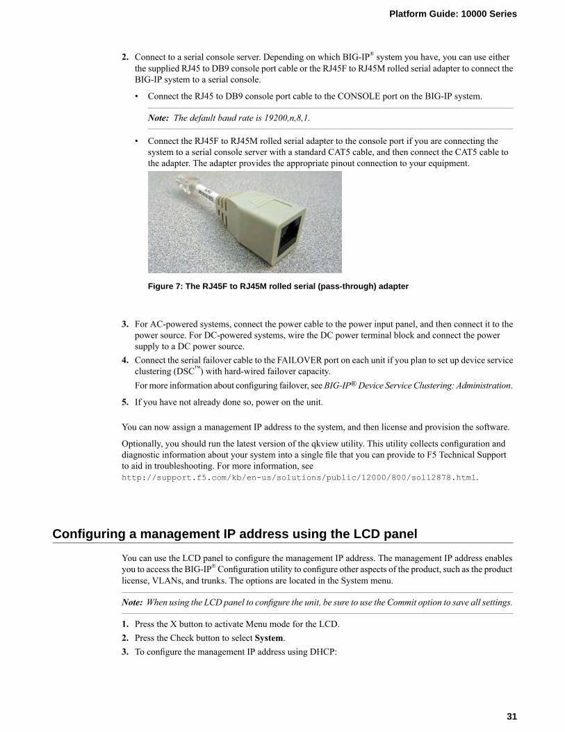
• Connect the RJ45F to RJ45M rolled serial adapter to the console port if you are connecting thesystem to a serial console server with a standard CAT5 cable, and then connect the CAT5 cable tothe adapter. The adapter provides the appropriate pinout connection to your equipment.
Figure 7: The RJ45F to RJ45M rolled serial (pass-through) adapter
3. For AC-powered systems, connect the power cable to the power input panel, and then connect it to thepower source. For DC-powered systems, wire the DC power terminal block and connect the powersupply to a DC power source.
4. Connect the serial failover cable to the FAILOVER port on each unit if you plan to set up device serviceclustering (DSC™) with hard-wired failover capacity.For more information about configuring failover, seeBIG-IP®Device Service Clustering: Administration.
5. If you have not already done so, power on the unit.
You can now assign a management IP address to the system, and then license and provision the software.
Optionally, you should run the latest version of the qkview utility. This utility collects configuration anddiagnostic information about your system into a single file that you can provide to F5 Technical Supportto aid in troubleshooting. For more information, seehttp://support.f5.com/kb/en-us/solutions/public/12000/800/sol12878.html.
Configuring a management IP address using the LCD panel
You can use the LCD panel to configure the management IP address. The management IP address enablesyou to access the BIG-IP®Configuration utility to configure other aspects of the product, such as the productlicense, VLANs, and trunks. The options are located in the System menu.
Note: When using the LCD panel to configure the unit, be sure to use the Commit option to save all settings.
1. Press the X button to activate Menu mode for the LCD.2. Press the Check button to select System.3. To configure the management IP address using DHCP:
31
Platform Guide: 10000 Series
a) Press the Check button to select DHCP.b) Press the Check button to select enabled.
4. To configure the management IP address manually:a) Press the Check button to selectManagement.b) Press the Check button to select Address Type, and then press the Check button again to select
either IPv4 or IPv6.c) Use the arrow keys to selectMgmt IP and press the Check button.d) Use the arrow keys to configure the management IP address.e) Use the arrow keys to select Prefix Length and press the Check button.f) Use the arrow keys to configure the length of the routing prefix for the IPv4 or IPv6 management
IP address.g) Use the arrow keys to selectMgmt Gateway and press the Check button.h) Use the arrow keys to configure the default route for the management interface.
5. Use the arrow keys to select Commit and press the Check button.
Licensing the platform
Once the management IP address is configured for the platform, you can use the BIG-IP® Configurationutility to license the appropriate BIG-IP software.
1. Using a Web browser, navigate to the management IP address that you assigned to the platform.Use this format where <mgmt_ip_address> is the management IP address you assigned:https://<mgmt_ip_address>
2. Type admin as the user name and admin as the password.If this is the first time you have accessed the Configuration utility, the first screen you see is the Licensescreen.
3. Follow the instructions in the Configuration utility to license the platform.
32
Platform Installation

Platform Maintenance
About maintaining the platform
The 10000 Series platform contains several components that you can replace individually without exchangingthe entire system. This platform contains these replaceable components:
• AC power supply• DC power supply• Fan tray• Hard drive
About AC power supplies
BIG-IP® platforms can support up to two AC power supplies. Some platforms come with only one powersupply by default. You can hot swap power supplies without powering down the system if there are twoinstalled and one remains installed and operational during the replacement process.
Figure 8: The 850W AC power supply
The platform supports power redundancy, which ensures that the system is unaffected if a single powersupply fails in a system containing more than one power supply.
Caution: Running without power supplies installed in all available bays in the platform can affect coolingand electromagnetic interference (EMI). If you need to run the unit with fewer power supplies, you mustinstall a blank supply bracket into any empty power supply bays. The blank supply bracket is required tomaintain proper airflow in the system. If you do not have a blank supply bracket, leave all supplies installedand unplug any unused power supplies.
Caution: As a safety precaution, the socket outlet must be installed near the equipment and be easilyaccessible.
Caution: Do not mix power supply models. If two power supplies are installed in the same system, use onlypower supplies of the same model.
Important: You should use only one power supply type (AC or DC) in a platform. AC andDC interoperabilityis not supported.
Important: This product is sensitive to electrostatic discharge (ESD). F5® recommends that you use properESD grounding procedures and equipment when you install or maintain the unit.
Note: Depending on the model and revision of the power supply, you might need either a Phillips or aslotted screwdriver to replace the power supply.
Installing an AC power supply
In the event of a power supply failure, you can replace an AC power supply without powering down thesystem, provided that there is at least one power supply operating during the replacement process.
1. Disconnect the AC power cord from the power supply.2. Loosen the power supply screw by turning it counterclockwise with an appropriate screwdriver, if
necessary.
Note: The screw is captive and cannot be removed from the assembly.
3. Remove the power supply from the system by pulling straight toward you.4. Slide the power supply into the empty slot.
Ensure that the power supply is fully seated in the chassis.
5. Tighten the screw into place.The power supply is connected to the system when you tighten the screw completely.
6. Attach the power cord to the new power supply.If the system does not boot after you apply power to the power supply, press the Check button on theLCD panel to begin booting the system.
About DC power supplies
BIG-IP® platforms can support up to two DC power supplies. Some platforms come with only one powersupply by default. You can hot swap power supplies without powering down the system if there are two
34
Platform Maintenance
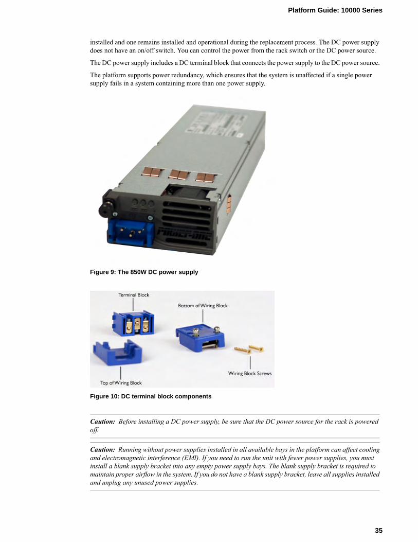
installed and one remains installed and operational during the replacement process. The DC power supplydoes not have an on/off switch. You can control the power from the rack switch or the DC power source.
The DC power supply includes a DC terminal block that connects the power supply to the DC power source.
The platform supports power redundancy, which ensures that the system is unaffected if a single powersupply fails in a system containing more than one power supply.
Figure 9: The 850W DC power supply
Figure 10: DC terminal block components
Caution: Before installing a DC power supply, be sure that the DC power source for the rack is poweredoff.
Caution: Running without power supplies installed in all available bays in the platform can affect coolingand electromagnetic interference (EMI). If you need to run the unit with fewer power supplies, you mustinstall a blank supply bracket into any empty power supply bays. The blank supply bracket is required tomaintain proper airflow in the system. If you do not have a blank supply bracket, leave all supplies installedand unplug any unused power supplies.
35
Platform Guide: 10000 Series
Caution: Before you begin to work with one of these platforms, refer to the DC-powered equipmentenvironmental warnings for this platform and review any safety requirements for the facilities where theDC-powered platforms will be installed.
Caution: Do not mix power supply models. If two power supplies are installed in the same system, use onlypower supplies of the same model.
Important: You should use only one power supply type (AC or DC) in a platform. AC andDC interoperabilityis not supported.
Important: This product is sensitive to electrostatic discharge (ESD). F5® recommends that you use properESD grounding procedures and equipment when you install or maintain the unit.
Important: The platform must be installed in a RESTRICTED ACCESS LOCATION, such as a centraloffice or customer premises environment.
Note: Copper cables used for grounding must meet appropriate safety standards.
Note: Bare conductors should be coated with an appropriate antioxidant before being crimped. Make sureto clean all unplated connectors, braided strap, and bus bars to a bright finish prior to coating them withthe antioxidant.
Note: The platform must be grounded to a common bonding network (CBN).
Note: The battery return terminals on the platform are in an isolated DC return (DC-I) configuration.
Wiring the DC power supply terminal block
You will need these tools to assemble and wire the DC terminal block:
• Wire stripping tool• Small Phillips screwdriver• Small flat-head screwdriver
The 850W DC power supply includes a DC terminal block. You connect the wires to the terminal blockand then insert the terminal block into the DC power supply.
1. Review the DC power supply label and determine the correct wire size for your installation.2. Use the wire stripping tool to remove 3/8 inch (9.56 mm) of insulation.
Important: Be sure to remove the appropriate amount of insulation from each wire. If you remove toomuch insulation, exposed wire protruding from the terminal block can create an electrical hazard. Ifyou do not remove enough insulation, the wire might not make proper contact with the terminal.
3. Thread the wires through the bottom of the terminal block, with the positive DC wire (typically red) onthe left, the chassis ground wire in the middle, and the negative DC wire (typically black) on the right.Note the orientation of the keying notch on the terminal block. When the keying notch is up, the positiveterminal is on the left.
36
Platform Maintenance

4. Insert each exposed wire into the appropriate connector on the terminal block.If necessary, use a small flat-head screwdriver to loosen the screws above the openings in the terminalblock to open the terminal connectors.
5. Attach the wired half of the terminal block to the other half of the terminal block, and then connect thetop of the terminal block until the two halves click into place.
6. Tighten the wire clamp screws on the bottom of the terminal block using a small flat-head screwdriver.7. Insert the two gold screws that are provided with the DC power supply kit into the top and bottom of
the terminal block, and then use a Phillips screwdriver to secure the two halves.
Installing a DC power supply
After you have assembled and wired the terminal block, you can install the DC power supply into theplatform and connect the platform to the DC power source. The DC power supply does not have an on/offswitch. You can control the power from the rack switch or the DC power source.
Important: When you connect the DC power source, F5 recommends that you follow the safety requirementsdefined for the facilities where the DC-powered platforms will be installed.
1. Make sure that the power from the DC power source is off.2. Ensure that the terminal block is not connected to the power supply before adding it to the unit.3. Remove the existing AC or DC power supply, if one is installed.
a) Disconnect the AC power cord or DC terminal block from the power supply.b) Loosen the power supply screw by turning it counterclockwise with an appropriate screwdriver, if
necessary.
Note: The screw that holds the ejector handle in place is captive and cannot be removed from theassembly.
37
Platform Guide: 10000 Series

c) Grasp the ejector handle and rotate it downward to eject the power supply from the system.
d) Remove the power supply from the system by pulling straight toward you.e) Ensure that the latch on the new power supply is in the down position, and then slide the power
supply into the power supply slot until the latch engages.f) Rotate the latch upward to fully seat the power supply.g) Tighten the screw into place.
Use 4 to 5 inch-pounds (0.45 to 0.56 Newton-meters) of torque on the screw. The power supply isconnected to the system when you tighten the screw completely.
4. Loosen the power supply screw on the DC power supply by using an appropriate screwdriver, if necessary.5. Slide the DC power supply into the power supply slot.6. Connect the terminal block that you assembled earlier to the DC power source and be sure to connect
the ground wire to a common bonding network (CBN).7. Power on the DC power source.
If the system does not boot after you power on the DC power source, press the Check button on the LCDpanel to begin booting the system.
About the fan tray
The BIG-IP® 10000 Series platform has a removable fan tray that is designed tomaintain airflow throughoutthe chassis. You can change or replace the fan tray as part of the routine maintenance of the unit, or in theevent of a fan failure. The fans in the fan tray run constantly while the unit is powered on. Over time, thefans can wear out, requiring you to replace the fan tray.
38
Platform Maintenance

Figure 11: The fan tray
Important: This product is sensitive to electrostatic discharge (ESD). F5® recommends that you use properESD grounding procedures and equipment when you install or maintain the unit.
Replacing the fan tray
You do not need special tools to replace the fan tray. You do not need to power down the unit when replacingthe fan tray; however, F5 highly recommends that you do not leave the unit operating without a fan tray forlonger than 30 seconds.
Caution: Operating the unit without a fan tray for more than 30 seconds might cause permanent damage.
1. Stand at the back of the platform and locate the ejector handle on the fan tray.2. Loosen the fan tray screws by turning them counterclockwise with a Phillips screwdriver, if necessary.
Note: The screws that hold the ejector handle in place are captive and cannot be removed from theassembly.
3. Grasp the ejector handle and rotate it downward to eject the fan tray from the system.
39
Platform Guide: 10000 Series

4. Remove the fan tray from the system by pulling straight toward you.
5. Ensure that the handle on the new fan tray is in the down position and slide the fan tray into the fan trayslot until the latch engages.
6. Rotate the handle upward to fully seat the fan tray.7. Tighten the screws into place.
The fan tray is connected to the system when you tighten the screws completely. Once seated, the fantray automatically powers up and begins circulating air through the chassis.
About the hard disk drives
The BIG-IP® 10000 Series platform includes two hot swappable hard disk drives (HDDs) and supports harddisk drive mirroring using RAID. You can change or replace the drives as part of routine maintenance ofthe unit or in the event of a drive failure.
Figure 12: Orientation of the 10000 Series platform hard drive bays
1. Hard disk drive bay 1
40
Platform Maintenance

2. Hard disk drive bay 2
Identifying a faulty hard disk drive
To access the hard disk drives (HDDs), you must first remove the bezel from the unit.
Before you remove the HDD from the system, you should first identify the faulty drive.
1. Open the Traffic Management Shell (tmsh).tmsh
2. View the status of the drives.show sys raid
A disk summary similar to this example displays:
---------------------Sys::Raid::Array: MD1---------------------Size (MB) 931.5K
---------------------------------------------------------Sys::Raid::ArrayMembersBay ID Serial Number Name Array Member Array Status---------------------------------------------------------1 WD-WXG1C52Y5088 HD2 yes failed2 WD-WXP1C52U8160 HD1 yes ok
-------------------------------------------------------------Sys::Raid::BayBay Shelf Name Serial Number Array Member Array Status-------------------------------------------------------------1 1 HD2 WD-WXG1C52Y5088 yes failed2 1 HD1 WD-WXP1C52U8160 yes ok
---------------------------------------------------------------------Sys::Raid::DiskName Serial Number Array Array Status Model
Member---------------------------------------------------------------------HD1 WD-WXP1C52U8160 yes ok ATA WDC WD1000CHTZ-0HD2 WD-WXG1C52Y5088 yes failed ATA WDC WD1000CHTZ-0
3. Make note of the bay number and serial number for the faulty HDD.
Note: You can also locate the last seven digits of the serial number on the front of the drive. The serialnumber is printed in its entirety on the labels, on top of the drive.
4. Before you physically remove the HDD from the system, remove the faulty drive from the array.The faulty drive is HD2 in the example.modify sys raid array MD1 remove HD2
5. (Optional) To ensure that you remove the correct drive, you can make the LED blink for the failed drive.The faulty drive is in bay 1 in the example.modify sys raid bay 1 flash-led
Note: If the faulty drive is not responsive, it might not blink the LED.
41
Platform Guide: 10000 Series

Note: The LED on the drive assembly continues to blink until the failed drive is removed. When thenew drive assembly is inserted, the LED blinks until the new drive assembly is added to the array andbegins the replication process.
Next, you can physically remove the HDD and replace it with the new one that you received from F5. Youdo not have to power down the system before you remove the drive.
Replacing a hard disk drive tray
After you have identified and removed the faulty hard disk drive (HDD) from the platform, you can installthe replacement drive that you received from F5®.
1. Remove the front bezel from the unit, if it is still installed.2. Verify the location of the faulty HDD by comparing the serial number and drive bay that you noted
earlier.
Note: The last seven digits of the serial number are printed on the front of the drive, behind the metalgrille.
Note: The STAT LED for the failed hard disk drive will be lit solid amber.
3. Remove the faulty drive:a) Loosen the HDD screw by turning it counterclockwise with an appropriate screwdriver, if necessary.
Note: The screw that holds the ejector handle in place is captive and cannot be removed from theassembly.
b) Grasp the ejector handle and pull straight toward you to eject the drive tray from the system.
4. Slide the new HDD into the empty drive bay, by pushing the front of the tray to engage the handle untilit swings closed.
5. Tighten the screw into place.Use 4 to 5 inch-pounds (0.45 to 0.56 Newton-meters) of torque on the screw. The HDD is connected tothe system when you tighten the screw completely.
6. View the status of the HDDs.tmsh show sys raid disk
A disk summary similar to this example, displays:
---------------------------------------------------------------Sys::Raid::DiskName Serial Number Array Array Status Model
Member---------------------------------------------------------------------HD1 WD-WXP1C52U8160 yes ok WDC WD1000CHTZ-0HD2 WD-WXG1C52Y5088 yes undefined WDC WD1000CHTZ-0
The status of the replacement HDD is undefined, and the serial number should match that of thereplacement drive.
42
Platform Maintenance
Note: If after a few seconds, you do not see the additional HDD in the disk summary, the drive mightnot be seated properly. If this occurs, remove and reinsert the drive.
7. Add the replacement drive (HD2 in the example) to the array.tmsh modify sys raid array MD1 add HD2
The status of the replacement drive should change to replicating, and the STAT LED should change tosolid green. The replication process typically takes between 15 and 45 minutes.
8. Attach the front bezel to the unit by grasping the bezel using the indentations located on either side.
Note: Failure to use the indentations could result in pinched fingers.
43
Platform Guide: 10000 Series


Environmental Guidelines
General environmental and installation guidelines
The 10000 platform is an industrial network appliance that is designed to be mounted in a standard 19-inchEIA rack. Follow these guidelines to adhere to safety precautions:
• Install the rack according to the manufacturer's instructions and check the rack for stability before placingequipment in it.
• Build and position the rack so that after you install the platform, the power supply and the vents on boththe front and back of the unit remain unobstructed. The platform must have adequate ventilation aroundthe unit at all times.
• Although not required, a 1U space between units makes it easier for you to remove the unit from therack in the event that the unit requires service. A 1U space between units also provides additional cablerouting options.
• Leaving at least 100 mm of space from the front panel of the unit to the rack front or rack door providesenough room for you to route the cables without excessive bending or insulation damage.
• A shelf or similar device is required to support the unit if only one person is installing the unit.• Do not allow the air temperature in the room to exceed 104°F (40°C).
Note: NEBS-certified units can withstand air temperatures of up to 131°F (55°C). Reaching the maximumtemperature is required only for a short period of time.
• Do not plug the unit into a branch circuit shared by more electronic equipment than the circuit is designedto manage safely at one time.
Warning: Due to the weight of the platform, at least two people are required to install this chassis into arack. Failing to use two people can result in severe personal injury or equipment damage.
Important: This product is sensitive to electrostatic discharge (ESD). F5® recommends that you use properESD grounding procedures and equipment when you install or maintain the unit.
Caution: Customers should not attempt to replace batteries. There is a risk of explosion if a battery isreplaced with an incorrect type. Field technicians should dispose of used batteries according to theinstructions.
Attention: Il y a risque d'explosion si la batterie est remplacée par une batterie de type incorrect. Mettreau rebut les batteries usagées conformément aux instructions.
Guidelines for AC-powered equipment
An AC-powered installation must meet these requirements:
• Use a 15 amp external branch circuit protection device to install the unit.• Use one power feed for each individual power supply.
Important: The platform must be installed in a RESTRICTED ACCESS LOCATION, such as a centraloffice or customer premises environment.
Note: The power cables included with this unit are for exclusive use with this unit and should not be usedwith other electrical appliances.
Note: These guidelines apply to STATIONARY PLUGGABLE EQUIPMENT TYPE A with simultaneousmultiple connections to the AC MAINS SUPPLY:
• The building installation shall provide a means for connection to protective earth; and• The equipment is to be connected to that means; and• A SERVICE PERSON shall check whether or not the socket-outlet from which the equipment is to be
powered provides a connection to the building protective earth. If not, the SERVICE PERSON shallarrange for the installation of a PROTECTIVEEARTHINGCONDUCTOR from the separate protectiveearthing terminal to the protective earth wire in the building.
Note: High leakage current. Earth connection essential before connecting supply.
46
Environmental Guidelines

Guidelines for DC-powered equipment
A DC-powered installation must meet these requirements:
• Use a 15 amp external branch circuit protection device to install the unit.• For permanently connected equipment, incorporate a readily accessible disconnect in the fixed wiring.• Use only copper conductors.• Cabling for the system must be grounded on both sides.• Use one power feed for each individual power supply.
NEBS platform guidelines
This information applies to the Network Equipment-Building System (NEBS) version of the 10000 Seriesplatform.
This equipment meets NEBS requirements per GR-63-CORE.
This equipment is suitable for installation in these locations:
• Network Telecommunication Facilities• Locations where the National Electrical Code (NEC) applies
Important: The intra-building interfaces of this platform, including Ethernet, are suitable for connectionto intra-building or unexposed wiring or cabling only with shielded and grounded cables at both ends. Theintra-building ports of the equipment must not be metallically connected to interfaces that connect to theoutside plant (OSP) or its wiring.
Note: You should coat bare conductors with an appropriate antioxidant compound before you make crimpconnections. You should bring all unplated connectors, braided strap, and bus bars to a bright finish andthen coat them with an antioxidant before you connect them.
Platform airflow diagram
When you install the platform into a rack, it is important to understand the unit's airflow direction so thatyou can ensure proper cooling.
The platform employs a negative pressure fan system, which draws cold air in from the front of the chassis.
47
Platform Guide: 10000 Series
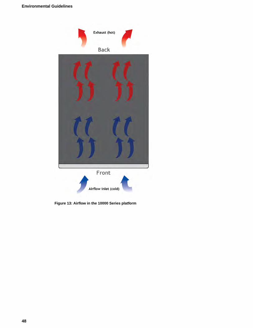
Figure 13: Airflow in the 10000 Series platform
48
Environmental Guidelines
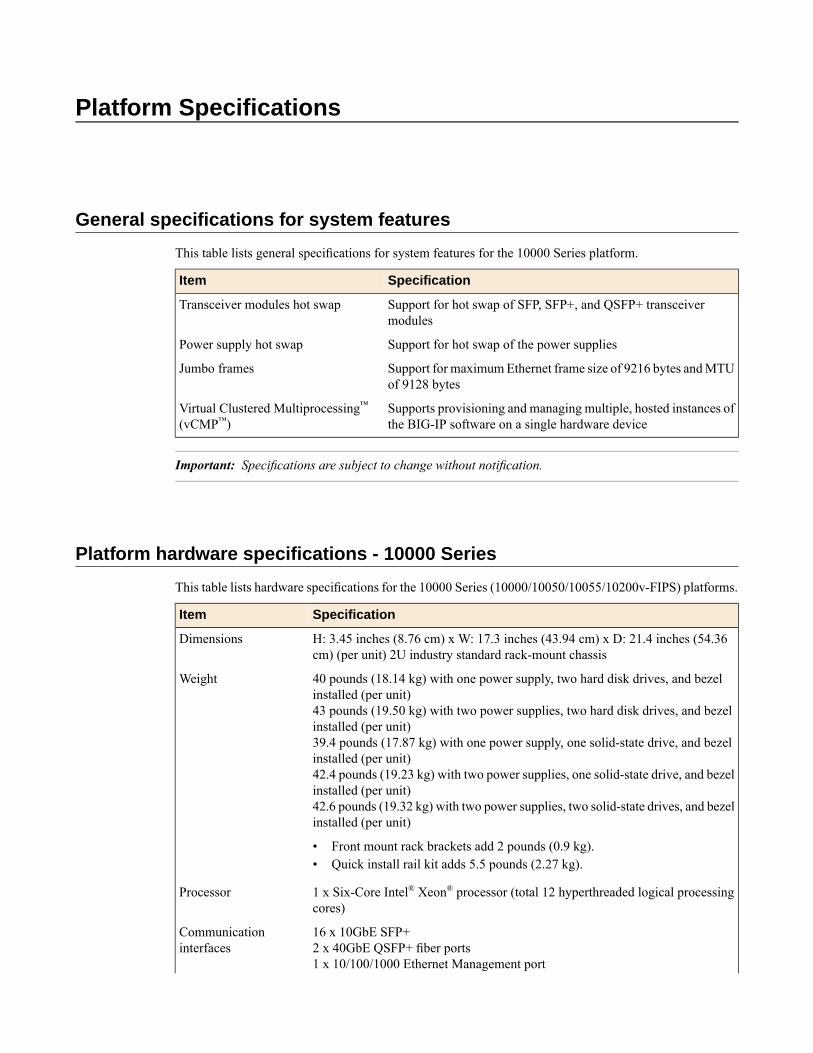
Platform Specifications
General specifications for system features
This table lists general specifications for system features for the 10000 Series platform.
SpecificationItem
Support for hot swap of SFP, SFP+, and QSFP+ transceivermodules
Transceiver modules hot swap
Support for hot swap of the power suppliesPower supply hot swap
Support for maximumEthernet frame size of 9216 bytes andMTUof 9128 bytes
Jumbo frames
Supports provisioning and managing multiple, hosted instances ofthe BIG-IP software on a single hardware device
Virtual Clustered Multiprocessing™(vCMP™)
Important: Specifications are subject to change without notification.
Platform hardware specifications - 10000 Series
This table lists hardware specifications for the 10000 Series (10000/10050/10055/10200v-FIPS) platforms.
SpecificationItem
H: 3.45 inches (8.76 cm) x W: 17.3 inches (43.94 cm) x D: 21.4 inches (54.36cm) (per unit) 2U industry standard rack-mount chassis
Dimensions
40 pounds (18.14 kg) with one power supply, two hard disk drives, and bezelinstalled (per unit)43 pounds (19.50 kg) with two power supplies, two hard disk drives, and bezelinstalled (per unit)
Weight
39.4 pounds (17.87 kg) with one power supply, one solid-state drive, and bezelinstalled (per unit)42.4 pounds (19.23 kg) with two power supplies, one solid-state drive, and bezelinstalled (per unit)42.6 pounds (19.32 kg) with two power supplies, two solid-state drives, and bezelinstalled (per unit)
• Front mount rack brackets add 2 pounds (0.9 kg).• Quick install rail kit adds 5.5 pounds (2.27 kg).
1 x Six-Core Intel® Xeon® processor (total 12 hyperthreaded logical processingcores)
Processor
16 x 10GbE SFP+2 x 40GbE QSFP+ fiber ports
Communicationinterfaces
1 x 10/100/1000 Ethernet Management port
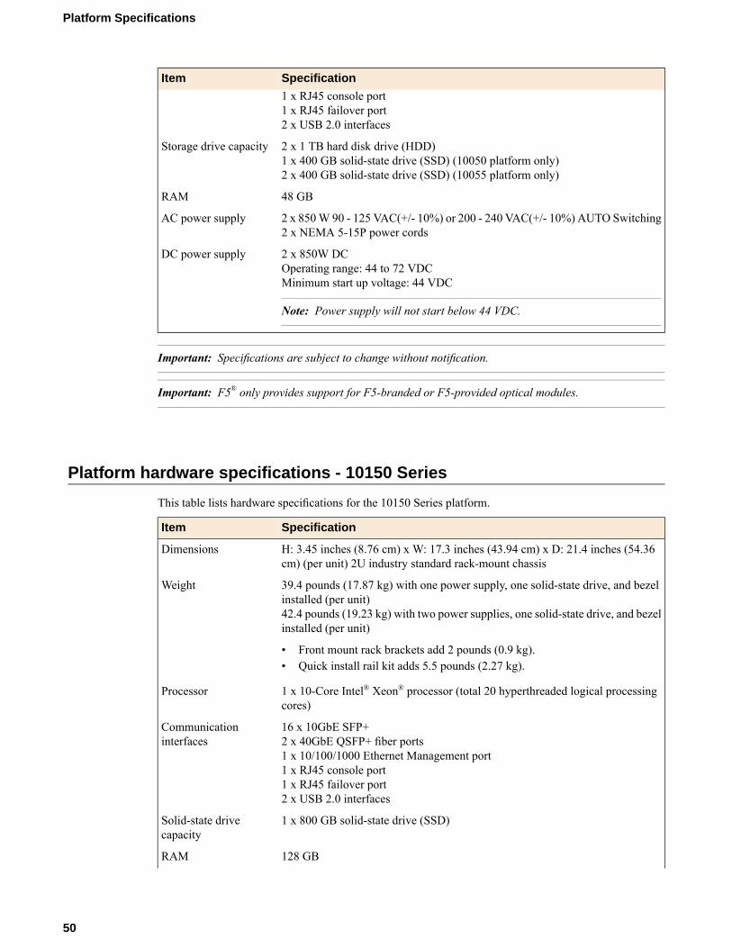
SpecificationItem1 x RJ45 console port1 x RJ45 failover port2 x USB 2.0 interfaces
2 x 1 TB hard disk drive (HDD)1 x 400 GB solid-state drive (SSD) (10050 platform only)
Storage drive capacity
2 x 400 GB solid-state drive (SSD) (10055 platform only)
48 GBRAM
2 x 850W 90 - 125 VAC(+/- 10%) or 200 - 240 VAC(+/- 10%) AUTO Switching2 x NEMA 5-15P power cords
AC power supply
2 x 850W DCOperating range: 44 to 72 VDC
DC power supply
Minimum start up voltage: 44 VDC
Note: Power supply will not start below 44 VDC.
Important: Specifications are subject to change without notification.
Important: F5® only provides support for F5-branded or F5-provided optical modules.
Platform hardware specifications - 10150 Series
This table lists hardware specifications for the 10150 Series platform.
SpecificationItem
H: 3.45 inches (8.76 cm) x W: 17.3 inches (43.94 cm) x D: 21.4 inches (54.36cm) (per unit) 2U industry standard rack-mount chassis
Dimensions
39.4 pounds (17.87 kg) with one power supply, one solid-state drive, and bezelinstalled (per unit)42.4 pounds (19.23 kg) with two power supplies, one solid-state drive, and bezelinstalled (per unit)
Weight
• Front mount rack brackets add 2 pounds (0.9 kg).• Quick install rail kit adds 5.5 pounds (2.27 kg).
1 x 10-Core Intel® Xeon® processor (total 20 hyperthreaded logical processingcores)
Processor
16 x 10GbE SFP+2 x 40GbE QSFP+ fiber ports
Communicationinterfaces
1 x 10/100/1000 Ethernet Management port1 x RJ45 console port1 x RJ45 failover port2 x USB 2.0 interfaces
1 x 800 GB solid-state drive (SSD)Solid-state drivecapacity
128 GBRAM
50
Platform Specifications
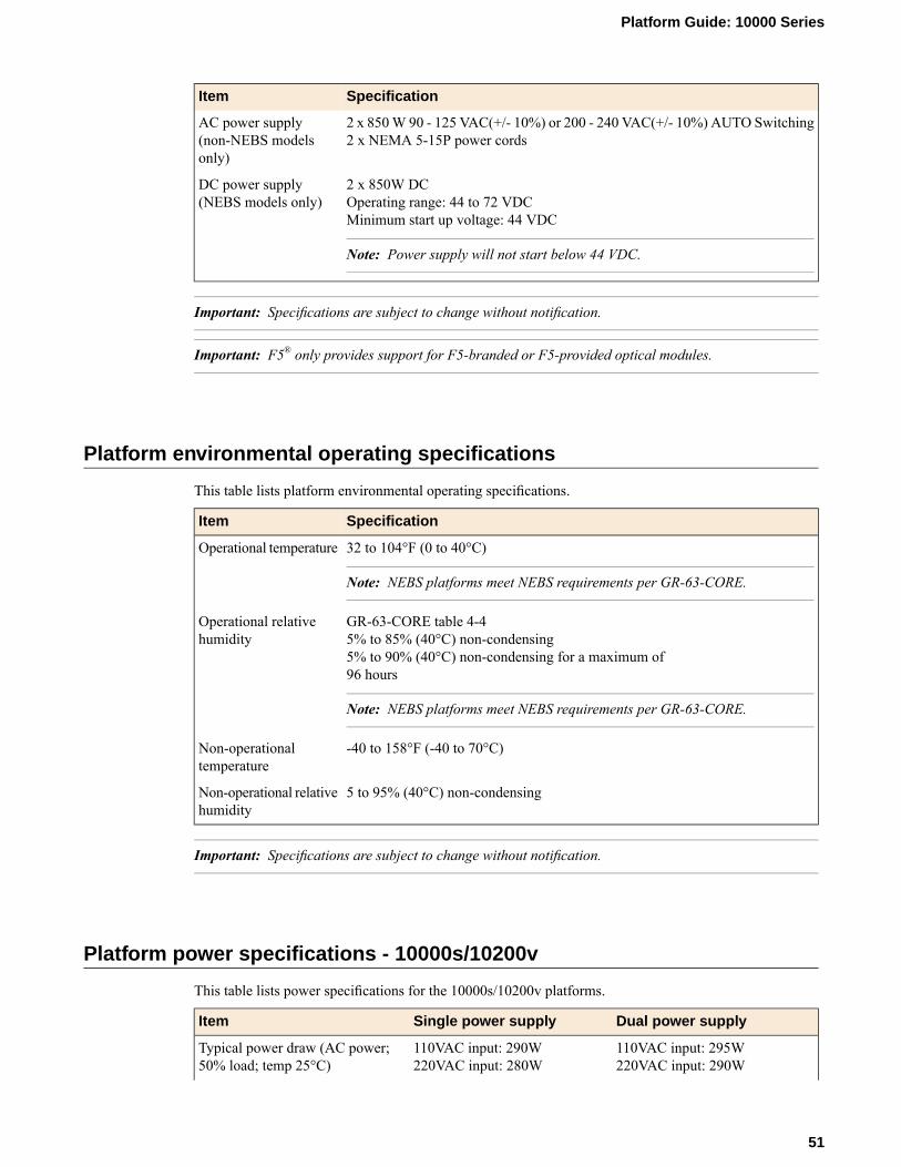
SpecificationItem
2 x 850W 90 - 125 VAC(+/- 10%) or 200 - 240 VAC(+/- 10%) AUTO Switching2 x NEMA 5-15P power cords
AC power supply(non-NEBS modelsonly)
2 x 850W DCOperating range: 44 to 72 VDC
DC power supply(NEBS models only)
Minimum start up voltage: 44 VDC
Note: Power supply will not start below 44 VDC.
Important: Specifications are subject to change without notification.
Important: F5® only provides support for F5-branded or F5-provided optical modules.
Platform environmental operating specifications
This table lists platform environmental operating specifications.
SpecificationItem
32 to 104°F (0 to 40°C)
Note: NEBS platforms meet NEBS requirements per GR-63-CORE.
Operational temperature
GR-63-CORE table 4-45% to 85% (40°C) non-condensing
Operational relativehumidity
5% to 90% (40°C) non-condensing for a maximum of96 hours
Note: NEBS platforms meet NEBS requirements per GR-63-CORE.
-40 to 158°F (-40 to 70°C)Non-operationaltemperature
5 to 95% (40°C) non-condensingNon-operational relativehumidity
Important: Specifications are subject to change without notification.
Platform power specifications - 10000s/10200v
This table lists power specifications for the 10000s/10200v platforms.
Dual power supplySingle power supplyItem
110VAC input: 295W220VAC input: 290W
110VAC input: 290W220VAC input: 280W
Typical power draw (AC power;50% load; temp 25°C)
51
Platform Guide: 10000 Series

Dual power supplySingle power supplyItem
48VDC input: 320W48VDC input: 300WTypical power draw (DC power;50% load; temp 25°C)
110VAC input: 470W240VAC input: 450W
110VAC input: 450W240VAC input: 430W
Maximum power draw (AC power)
48VDC input: 450W48VDC input: 430WMaximum power draw (DC power)
110VAC input: 1010 BTU/hour220VAC input: 990 BTU/hour
110VAC input: 990 BTU/hour220VAC input: 955 BTU/hour
Typical heat generated (AC power)
48VDC input: 1095 BTU/hour48VDC input: 1025 BTU/hourTypical heat generated (DC power)
1535 BTU/hour1470 BTU/hourMaximum heat generated (ACpower)
1535 BTU/hour1470 BTU/hourMaximum heat generated (DCpower)
Important: Specifications are subject to change without notification.
Platform power specifications - 10050 Series
This table lists power specifications for the 10050 Series platform.
Dual power supplySingle power supplyItem
110VAC input: 290W220VAC input: 290W
110VAC input: 280W220VAC input: 265W
Typical power draw (AC power;50% load; temp 25°C)
48VDC input: 310W48VDC input: 300WTypical power draw (DC power;50% load; temp 25°C)
110VAC input: 350W240VAC input: 355W
110VAC input: 345W240VAC input: 315W
Maximum power draw (AC power)
48VDC input: 375W48VDC input: 365WMaximum power draw (DC power)
110VAC input: 990 BTU/hour220VAC input: 990 BTU/hour
110VAC input: 960 BTU/hour220VAC input: 900 BTU/hour
Typical heat generated (AC power)
48VDC input: 1050 BTU/hour48VDC input: 1015 BTU/hourTypical heat generated (DC power)
1200 BTU/hour1065 BTU/hourMaximum heat generated (ACpower)
1280 BTU/hour1235 BTU/hourMaximum heat generated (DCpower)
Important: Specifications are subject to change without notification.
52
Platform Specifications

Platform power specifications - 10200v-SSL
This table lists power specifications for the 10200v-SSL platform.
Important: Platforms that contain solid-state drives (SSDs) consume an additional 10W (maximum) perdrive over platforms that contain hard disk drives (HDDs), approximately.
Dual power supplySingle power supplyItem
110VAC input: 300W220VAC input: 300W
110VAC input: 290W220VAC input: 290W
Typical power draw (AC power;50% load; temp 25°C)
48VDC input: 335W48VDC input: 305WTypical power draw (DC power;50% load; temp 25°C)
110VAC input: 415W90VAC input: 415WMaximum power draw (AC power)
44VDC input: 445W44VDC input: 425WMaximum power draw (DC power)
110VAC input: 1025 BTU/hour220VAC input: 1025 BTU/hour
110VAC input: 990 BTU/hour220VAC input: 990 BTU/hour
Typical heat generated (AC power)
48VDC input: 1145 BTU/hour48VDC input: 1045 BTU/hourTypical heat generated (DC power)
110VAC input: 1420 BTU/hour90VAC input: 1420 BTU/hourMaximum heat generated (ACpower)
44VDC input: 1520 BTU/hour44VDC input: 1450 BTU/hourMaximum heat generated (DCpower)
Important: Specifications are subject to change without notification.
Platform power specifications - 10150 Series
This table lists power specifications for the 10150 Series platform.
Dual power supplySingle power supplyItem
320W290WTypical power draw (DC power;48VDC; 50% load; temp 25°C)
400W380WMaximum power draw (DC power)
1095 BTU/hour990 BTU/hourTypical heat generated (DC power)
1365 BTU/hour1300 BTU/hourMaximum heat generated (DCpower)
Important: Specifications are subject to change without notification.
53
Platform Guide: 10000 Series
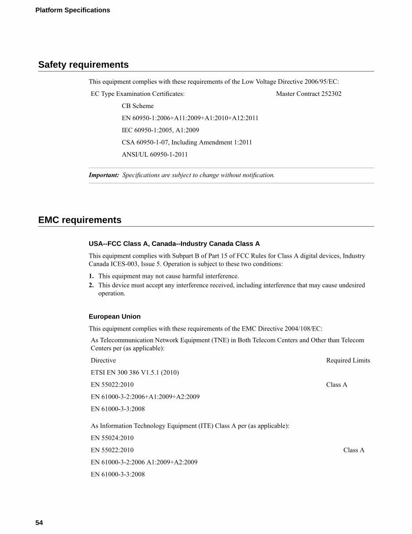
Safety requirements
This equipment complies with these requirements of the Low Voltage Directive 2006/95/EC:
Master Contract 252302EC Type Examination Certificates:
CB Scheme
EN 60950-1:2006+A11:2009+A1:2010+A12:2011
IEC 60950-1:2005, A1:2009
CSA 60950-1-07, Including Amendment 1:2011
ANSI/UL 60950-1-2011
Important: Specifications are subject to change without notification.
EMC requirements
USA--FCC Class A, Canada--Industry Canada Class A
This equipment complies with Subpart B of Part 15 of FCC Rules for Class A digital devices, IndustryCanada ICES-003, Issue 5. Operation is subject to these two conditions:
1. This equipment may not cause harmful interference.2. This device must accept any interference received, including interference that may cause undesired
operation.
European Union
This equipment complies with these requirements of the EMC Directive 2004/108/EC:
As Telecommunication Network Equipment (TNE) in Both Telecom Centers and Other than TelecomCenters per (as applicable):
Required LimitsDirective
ETSI EN 300 386 V1.5.1 (2010)
Class AEN 55022:2010
EN 61000-3-2:2006+A1:2009+A2:2009
EN 61000-3-3:2008
As Information Technology Equipment (ITE) Class A per (as applicable):
EN 55024:2010
Class AEN 55022:2010
EN 61000-3-2:2006 A1:2009+A2:2009
EN 61000-3-3:2008
54
Platform Specifications

Important: Specifications are subject to change without notification.
Acoustic, airflow, and altitude specifications
This table lists acoustic levels, airflow movement, and operational altitude specifications for the 10000Series platform.
ValueUnitsDetailSpecification type
6464
dBAdBA
FrontLeft
Acoustic 1
62dBARight71dBARear
Top 64
13,00040,000
FeetFeet
OperationalNon-operational
Altitude 2
260 (max)CFMOpen airAirflow 3
Important: Specifications are subject to change without notification.
1 All measurements taken at 0.6 meter with one power supply operational and fans at 75% duty cycle. Measurementsrecorded in Decibels A-weighting.
2 Per BELCOREGR-63-CORE, section 4.1.3: This unit is functional when installed at elevations between 60m (197 feet)below sea level and 1800m (6000 feet) above sea level at the aisle ambient temperatures of 40°C.
3 Fan Tray airflow measurements taken at 100% duty cycle and in open air.
55
Platform Guide: 10000 Series


China RoHS Requirements
Hazardous substance levels for China
This table shows how the BIG-IP® 10000 Series platform components conform to the Restriction of HazardousSubstances (RoHS) Directive standards for China.


Repackaging Guidelines
About repackaging the platform
If it becomes necessary to transport the platform to another location or return it to F5® Networks, theseguidelines will help ensure that you repackage the platform properly.
If you are running BIG-IP® software version 11.6 or later, you can perform a disk erase operation to eraseall sensitive data from solid-state drives (SSDs) and hard disk drives (HDDs) before you return a platformto F5. For more information, see F5® Platforms: Essentials.
Important: Before returning any equipment, contact F5 to obtain a Service Order (SO) or Return MaterialAuthorization (RMA) case number.
Important: Youmust use shipping materials and packaging provided by F5 when repackaging the platform.
Note: Be sure to keep a record of the tracking number and ship date. These will be needed to track lostshipments.
Note: Do not include any cables, removable XFP/SFP modules, GBICs, or other peripheral items if youare returning the platform to F5.
Repackaging the platform
The 10000 Series platform must be shipped in F5®-provided packaging.
Caution: To ensure your safety and to prevent damage to the platform, we highly recommend that youhave at least two people remove the platform from the rack and repackage it into the shipping box.
1. Halt the platform using the LCD panel.2. Disconnect the AC power cord or DC power supply terminal from the power supplies.3. Disconnect the network cables and other cables from the platform, and then remove any optical modules.4. Remove the platform from the rack.5. Wrap the platform in the plastic wrapping, if available.6. Lift the foam flaps and place the platform into the shipping box, and then place the accessory boxes in
the foam inserts.
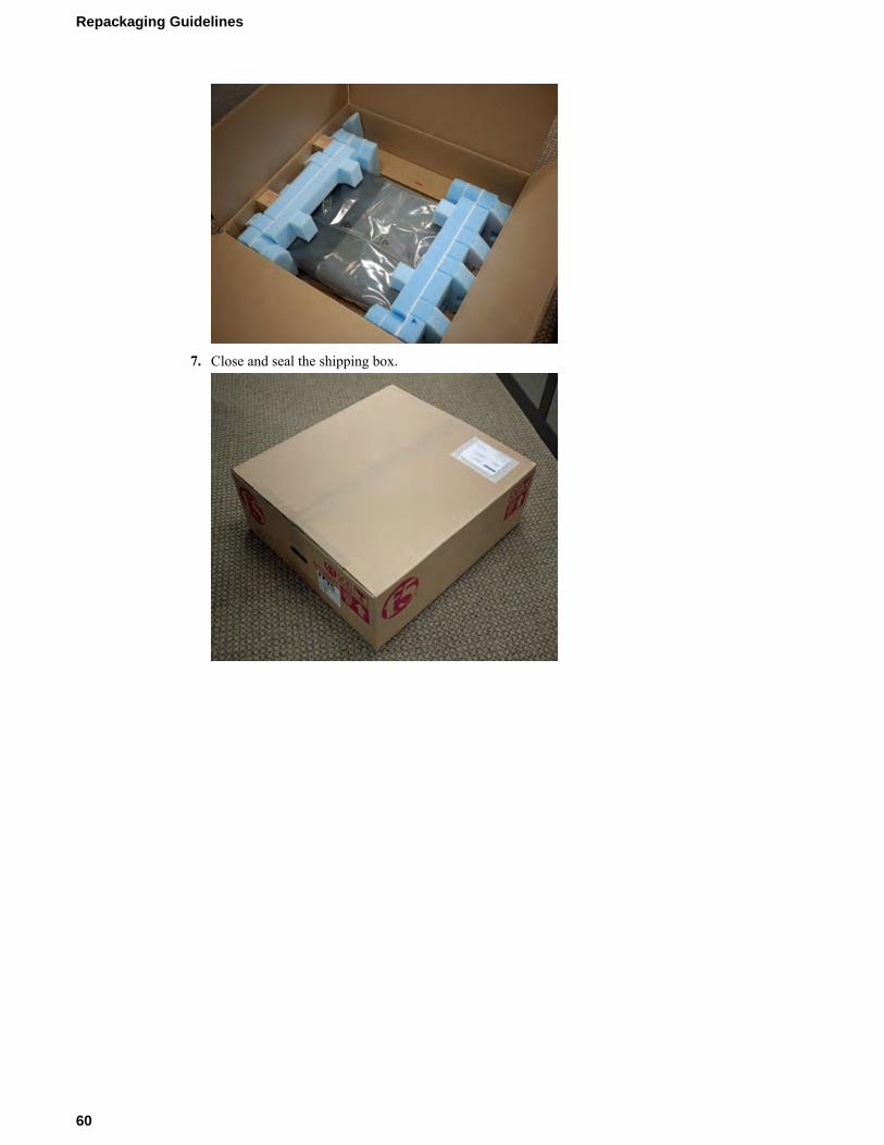
7. Close and seal the shipping box.
60
Repackaging Guidelines

Returned Material Data Security Statement
About returned material data security
Follow these data security guidelines when returning equipment to F5® for reprocessing or repair. Theguidelines include reprocessing procedures and optional customer-end procedures.
About memory technologies used in F5 equipment
F5® equipment contains volatile, battery-backed volatile, and non-volatile memory. Volatile memory losesall traces of data on power down. Battery-backed volatile memory retains data as long as battery charge ismaintained. Non-volatile memory retains data indefinitely.
Volatile memory
Volatile memory loses all traces of data on power down; therefore, customer data that is stored in volatilememory is secure when power is removed from the platform. No further action is required by customersfor equipment that includes volatile memory.
Battery-backed volatile memory
This F5® platform contains a coin battery for maintaining BIOS settings and the system clock. All datamaintained by the coin battery is used only for system specific tasks. No customer data is maintained bythe battery-backed volatile memory. No further action is required by customers for equipment that includesvolatile memory.
Non-volatile memory
F5® platforms include various non-volatile memory components. These non-volatile memory componentscan be categorized as either user inaccessible or user accessible.
Inaccessible non-volatile memory components are programmed during manufacture or software installation.The data stored in user inaccessible non-volatile memory is used for setting voltage levels, determining thesequence of operational events, and the managing appliance operational condition. Data held within userinaccessible, non-volatilememory represents no data security risk to customers. User inaccessible, non-volatilememory cannot be modified by appliance users, and therefore, contains no customer data.
Inaccessible non-volatile memory
This table lists the inaccessible non-volatile memory in this system.
Customer dataDataDescription
NoFirmwareProgrammable firmware stores
NoPlatform ID, serial number, part number, andso on.
Switch Card SEEPROM
NoPHY MAC addressPHY EEPROMs
Accessible non-volatile memory
This table lists the accessible non-volatile memory in this system. Not all platform variants include all ofthese non-volatile memory items.
Data security methodCustomer dataDataDescription
Standard reprocessing orcustomer removal
YesF5® product software,customer configuration,and log files
Hard disk drive (HDD)
Standard reprocessing orcustomer removal
YesF5 product software,customer configurationand log files
Solid-state drive (SSD)
Standard reprocessing orcustomer action
YesAOM boot code andcustomer customconfiguration
Always-OnManagement(AOM) Flash chip(soldered-down flashchip)
Standard reprocessing orcustomer action
YesFIPS security domain andprivate keys
FIPS card (if present)
About removing data from F5 components
For components that contain sensitive customer data and cannot be removed from your F5® system, youcan take optional steps to remove the data from these components before you return the system to F5 forprocessing.
Removing sensitive data from storage drives
The hard disk drive (HDD) and solid-state drive (SSD) components included in F5® platforms might includesensitive customer data. If you purchase the HDD removal SKU, you can remove the HDD/SSD and coinbattery, and these components will be replaced during F5 reprocessing. Otherwise, HDD and SSD componentsare processed by F5 through standard processing. You can perform a disk erase operation on your systemto remove sensitive customer data.
Perform a disk erase operation using one of these methods:
• On systems running BIG-IP® software version 11.6.0 and later, you can use the F5 Disk Eraseutility to remove all data on hard disk drives (HDDs) or solid-state drives (SSDs) using a single-pass,zero write disk erase operation. For more information, seehttp://support.f5.com/kb/en-us/solutions/public/15000/500/sol15521.html.
• On systems running earlier versions of BIG-IP software, you can create and use a bootable USBdrive to rebuild the system with a clean image of BIG-IP software. This runs a disk erase operation
62
Returned Material Data Security Statement

and removes the master boot record (MBR). For more information seehttp://support.f5.com/kb/en-us/solutions/public/13000/100/sol13164.html.
Removing IP address data from Always-On Management
If you have configured an IP address for the Always-On Management (AOM) subsystem, you can removethe customized IP address from the system before returning it to F5® Networks.
1. Connect to the system using the serial console.2. Open the AOM Command Menu.
Esc (
3. Assign a new management IP address, netmask, and gateway:
• To use DHCP to assign the addresses, type y when prompted about using DHCP.• To manually assign the addresses, type n when prompted about using DHCP. At the prompts, type
values for IP address (required), netmask (required), and gateway (optional).
A confirmation message displays the configured management IP address, netmask, and gateway.4. (Optional) Type i to verify the assigned addresses.
Removing sensitive data from an internal hardware security module (HSM)
If the system includes an internal hardware security module (HSM), also referred to as a FIPS card, youcan remove the sensitive customer data from HSM before returning it to F5® Networks.
Important: The HSM cannot be removed from the platform.
1. Use the Configuration utility to delete all key/certificate pairs.a) On the Main tab, click System > File Management > SSL Certificate List.
This displays the list of certificates installed on the system.b) Select the certificates that you want to delete and click Delete.
This removes all .crt, .exp, and .key files from the system.
2. Log on to the command line of the system using an account with root access.3. Initialize the HSM and reconfigure it using fictitious data.
run util fips-util -f init
For more information on using this command on a FIPS platform, see BIG-IP® Platform: FIPSAdministration.
Important: This deletes all keys and makes any previously exported keys unusable.
63
Platform Guide: 10000 Series


Index
10G direct attach copper cables 2240GbE interfaces, See QSFP+ interfaces.40G interfaces, See QSFP+ interfaces.
A
acoustic specifications 55AC-powered equipment
connecting to a power source 30guidelines 46
AC power supplyhot swapping 33
airflow specifications 55alarm LED 15alert conditions
clearing 14defining custom alerts 15
altitude operational specifications 55Always-On Management (AOM)
about 22configuring management network 24disabling network configuration 25setting SSH idle session timeout 24
AOM, See Always-On Management (AOM).AOM Command Menu
about 22about the host console capture buffer (H) option 25accessing using serial console 23accessing using SSH 24disabling the host console capture buffer 26enabling host console capture buffer 25options 22showing the host console capture buffer 25
AOM host console capture bufferabout 25disabling 26enabling 25showing 25
AOM IP address dataremoving 63
Auto-MDI/MDIX 18
B
bezelinstalling 28
BIG-IP Configuration utilitylicensing the platform 32managing interfaces 16viewing status of all interfaces 18
breakout cable 19
C
cables10G direct attach copper 22connecting 30
cables (continued)failover 30power 30
CD/DVD-ROM drivessupport for 11
chassisDC power supplies 37ventilation 45, 47
chassis ground luglocating 29
chassis ground wire 36Check button
clearing alerts 14power on 13
China material content listing, See China RoHS Directivestandards.China RoHS Directive standards 57clear alert operation 14Configuration utility, See BIG-IP Configuration utility.cooling system
platform 47
D
data communications equipment (DCE) 18data terminal equipment (DTE) 18Date and time screen 13DC-powered equipment
guidelines 47NEBS guidelines 47voltage 30
DC power supplyconnecting the DC power source 37hot swapping 34supported model 34terminal block 36wiring the DC power supply terminal 37wiring the DC terminal block 36
DC terminal blockassembling and preparing 36
device service clustering (DSC) 30disk erase operation
performing 59DSC, See device service clustering (DSC).duplex mode 18dynamic routing protocols 49
E
electromagnetic compatibility (EMC) certifications 54electrostatic discharge (ESD) 45EMC certifications 54environmental guidelines 57
See also China RoHS Directive standards.environmental operating specifications 51ESD, See electrostatic discharge (ESD).Ethernet hub requirements 11
65
Index

F
failover cables 30fan tray
about 38replacing the fan tray 39
FIPS cards, See hardware security module (HSM).FIPS platform 9front mount
kit hardware 27front-mounting kits
installing 27
G
Gigabit Ethernet 11ground lugs
connecting to ground terminal 30locating 9, 29
guidelinesbattery replacement 45
H
halting 12halt operation 13hard disk drive (HDD)
40disk erase operation 59identifying a faulty hard disk drive 41replacing 42
hard disk drives (HDDs)specifications 49
hardwareAC-powered equipment 46DC-powered equipment 47
hardware requirementsperipherals 11
hardware security module (HSM)removing data 63
hardware specifications 49–50hard-wired failover 30hazardous substance restrictions, See China RoHS Directivestandards.Hold mode 13hot swap
AC power supply 33DC power supply 34, 37power supplies 49transceiver modules 49
hubs 11
I
indicator LEDsabout 14behavior 15locating 9
installationguidelines 45performing using serial console 11recommendations for 45
installation (continued)spacing between units 45
interfacesabout 16configuring 16duplex mode 18managing 16media type 18QSFP+ 19viewing status of all interfaces using Configuration utility18viewing status of all interfaces using tmsh 17viewing status of a specific interface using tmsh 16viewing valid media types 19viewing valid media types using tmsh 18
J
jumbo frames 49
L
LCD config menu 12LCD menus 11LCD panel
about 11backlight option 12brightness option 12contrast option 12control buttons 11menus 11pausing on a screen 13using 13
LEDalarm 15network interface 21power supply 15RJ45 interface 21SFP+ interface 21status 14
licenseconfiguring 32
low voltage directive 54
M
maintenanceAC power supply 34DC power supply 37fan tray 39replaceable components 33
management interfaceconnecting Ethernet cable 30enabling or disabling DHCP 12setting the gateway 12setting the IP address 12setting the netmask 12
management IP addressesconfiguring using LCD panel 31
memory technologiesabout 61battery-backed volatile memory 61
66
Index

memory technologies (continued)non-volatile memory 61volatile memory 61
N
NEBSair temperature 45guidelines 47operating requirements 51platform 9
negative pressure fan system 47netbooting 12network interface LEDs
appearance of 21QSFP+ 22RJ45 21SFP 21SFP+ 21
network interface specifications, See transceiver modulespecifications.non-volatile memory
types 61
O
optical interfaces, See interfaces.
P
pass-through adapter, See RJ45F to RJ45M rolled serialadapter.pinouts
cables 22specifications 22
platformabout 9airflow 47clearing alerts 14cooling 47FIPS 9grounding 29halting 13hardware provided 10installing 27managing interfaces 16NEBS 9photos 9powering on 13putting into standby mode 14repackaging 59replaceable components 33resetting 14returning for RMA 59SSD 9SSL 9transporting 59ventilation 45, 47
platform specificationsdisk drive 49–50environmental 51hardware 49–50
platform specifications (continued)memory 49–50operating 51power for 10000s/10200v platforms 51power for 10050 Series platform 52power for 10150 Series platform 53power for 10200v-SSL platform 53power supply 49–50processor 49–50solid-state drive 49
ports 9power cables 30power cord
adding an AC power supply 34powering off
host subsystem 14power on operation 13power specifications
10000s/10200v platforms 5110050 Series platform 5210150 Series platform 5310200v-SSL platform 53
power suppliesLED 15
power supplyinstalling a DC power supply 37replacing a DC power supply 37replacing an AC power supply 34specifications 49–50wiring the DC terminal block 36
Product version screen 13PXE servers
installing software from 12
Q
qkview utility 30QSFP+ interfaces
about 19breakout cables 19configuring bundling using the Configuration utility 20configuring bundling using tmsh 20LEDs 22orderable components 19
quick-install rail kits 28
R
rack mountears 27front mount 27general environmental guidelines 45quick-install rail kits 28screws 27types of kits 27
rack rails, See rail mount.RAID status screen 13rail lock brackets
installing 29rail mount
installing rail lock brackets 29quick-install rail kits 28
67
Index

rebooting 12redundancy
system 30redundant system configuration 30
See also device service clustering (DSC).remote administration 11repackaging
about 59platform 59
replaceable componentsabout 33AC power supply 33DC power supply 34, 37fan tray 38hard disk drive (HDD) 40
reset operation 14returned material data security
about 61accessible non-volatile memory 62battery-backed volatile memory 61inaccessible non-volatile memory 61memory technologies 61non-volatile memory 61removing data from components 62volatile memory 61
Return Material Authorization (RMA) 59RJ45F to RJ45M rolled serial adapter 30RJ45 interface LEDs 21RMA, See Return Material Authorization (RMA).Rotate mode 13
S
safety agency approvals 54Screens menu 13serial console
hardware installation 11, 30serial failover 30serial port
setting baud rate 12SFP+ hot swap 49SFP+ interface LEDs 21SFP interface LEDs 21solid state drive (SSD)
disk erase operation 59solid-state drive (SSD)
power consumption in 10050 Series platform 52power consumption in 10150 Series platform 53supported platforms 9
solid-state drives (SSDs)specifications 49–50
specificationsacoustic 55airflow 55altitude operational 55China RoHS 57disk drive 49–50hardware 49–50hardware operation 51memory 49–50
specifications (continued)power for 10000s/10200v platforms 51power for 10050 Series platform 52power for 10150 Series platform 53power for 10200v-SSL platform 53power supply 49–50processor 49–50solid-state drive 49system features 49
SSD, See solid-state drive (SSD).SSL platform 9standby mode 14status LED 14storage drives
removing sensitive data 62switches 11system
resetting 22resolving when locked up 22
System information screen 13System menu 12
T
TMOS, See Traffic Management Operating System.tmsh, See Traffic Management Shell (tmsh).Traffic Management Operating System
relation to AOM 22Traffic Management Shell (tmsh)
interface command 18managing interfaces 16viewing status of all interfaces 17viewing the status of a specific interface 16viewing valid media types 19
transceiver module specifications 22transporting the platform 59two-post racks 27
U
USB flash drivessupport for 11
USB portssupported CD/DVD-ROM drives 11
V
vCMPcompatibility with FIPS-certified platforms 9platform support 49
ventilation 45, 47Virtual Clustered Multiprocessing, See vCMP.
W
warningsenvironmental 45
warnings, environmental 57See also China RoHS Directive standards.
68
Index