plastic design in high strength steel the second-order
TRANSCRIPT

Plastic Design in High strength Steel
THE SECOND-ORDER ELASTIC ANALYSIS OF
PLANE RIGID FRAMES
by
H. B. Harrison
This work has been carried out 3S part of aninvestigation sponsored jointly by the WeldingResearch Council and the Department of the Navywith funds furnished by the following:
American Institute of Steel ConstructionAmerican Iron and Steel InstituteInstitute of Research, Lehigh UniversityColumn Research Council (Advisory)Office of Naval ResearchBur.eau of ShipsBureau of Yards and Docks
Reproduction of this report in whole or in partis permitted for any purpose of the UnitedStates Government.
November, 1965
,Fritz Engineering Laboratory
Department of Civil EngineeringLehigh University
Bethlehem, Pennsylvania
Fritz Engineering Laboratory Report No. 297.17

297.17
SYNOPSIS
A computer program is described which will carry out both a
first-order and'a second-order elastic analysis of plane rigid
frames. The program will accept data describing a frame in terms
of its joint co-ordinates, member properties and connections
together with the loads for which an analysis is required. A
sequence of load sets can be analyzed so that it is possible to
use the results to compute the elastic stability load for a frame.
In the second order analysis, account is taken of the change in
flexural stiffness of a member caused by axial load and in
addition, the equilibrium equations are formulated for the
deformed shape of the frame. The analysis is based on the
displacement method using matrix techniques with the second order
solution .obtained by an iterative process.
The frame size that can be handled by the program is a
function of the store capacity available in any computer and the
program limitation7 in this regard are discussed in detail. The
program is in the Fortran language and was developed to aid in
the computation of frame strengths in a study of the economics of
using high-tensile steel in rigid structures.
i

TABLE OF CONTENTS
297.17
Page
SYNOPSIS i
I. INTRODUCTION 1
II. BASIC PROGRAM REQUIREMENTS 4
III. DISPLACEMENT ANALYSIS 6
IV. THE STATICS MATRIX 8
V. THE MEMBER STIFFNESS MATRIX lO
VI. PROGRAM OPERATION 12
VII. DEMONSTRATION EXAMPLES 15
VIII. PROGRAM LIMITATIONS 21
IX. CONCLUSION 23
X. ACKNOWLEDGEMENTS 24
XI. NOMENCLATURE 25
XII. APPENDICES 27
A. Fortran Program 28B. Solution to Frame Example 1 34C. Solution to Frame Example 2 35
XIII. TABLES AND FIGURES 36
XIV. REFERENCES 53
ii.

,.;,."J. '". C-'l'~
II ~
II
297.17
L INTRODUCTION
When high strength steels are used in the design of rigid
frames, ..the weight and cost reductions are quite attractive when
'the frame strength can be, accurately estimated by simple plasti8
theory. (lY 'However, this theory will overestimate frame strength, ,
whenever,axial stresses are large as in multi-story frames even
of mild steel and also whenever the deformations under load are
sufficiently large to 'invalidate the formulation of equilibrium'
in terms of the unloaded frame ,configuration. The' latter effect
becomes serious when lighter sections of high strength steel are
substituted in a, frame design for'stiffer sections, of equal
. h . d' b" h' (2 3) ,plastlc streng.t " lIT. mil. steel. Tt· has' een s" own' that the
,effects of strain-hardening in mild steel can cqmpensate for. the
de'formatioR effects in some frames, but such an influence is likely
to be", less s'ignificant' when more flexible, frames' are proportioned
in high-"strength steel.
In any, e'80nomic study of the value in us inghigh~s~re:hgth'
steel,iIi., building'fram~s;,it is necessary to have available aI'
metho.d,fo.r, es:timat,ing'the, maximum frame strength so that design,- ';'~
compari~ons may be made. But the problem of computing the real'
maximum ·,stren,g~h of a frame; allowing for plasticity' and defor;-,.,
mat,ion" is still quite a :E0rmidable one. It has, been: suggested(~!{:.,,'J 0'
that the maximum strength of a steel frame might be'estimated
1

297'.17
using one half of the harmonic mean of the plastic failure load
and the elastic stability load. Many formulae for pinned steel
columns are based upon a similar principle. Computer programs
are available(S,6) which can lessen considerably the effort
required in determining the plastic failure load for a frame
but the accurate calculation of the elastic stability load is a
formidable problem. Analytical solutions for some classes of
frames are available(7) and computational methods using the
Southwell Plot method have also been proposed.(8) It is possible
to predict the elastic stability load with close accuracy using
results' obtained from a second-order elastic analysis. A second-
order analysis differs from a first-order or linear analysis
because of 'the necessity to take into account the changes in
flexural stiffness of each member caused by axial loading and
as well, the equations of equilibrium must be formulated for the
deformed shape of the frame rather than for its initial unloaded
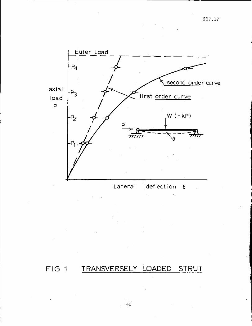
shape. A second-order deformation curve will become close to
horizontal as the loads approach the elastic stability values.
This behavior is illustrated in !ig. 1 for the case of a
centrally-loaded beam subjected to axial compression. If the
nume:rical values for load and transverse de flection' are known
at 4 or S,points on such a load-defJ"ection curve, the elastic
stability or Euler load can be predicted accuratelyby'plotting
the ,ratio of, transverse load to transverse de flection against the
value of axial load. This is shown in Fig. 2. In effect, the
2

.--' ..
297.17
former ratio is a measure of the resistance to flexure or stiff
ness of the member and the stiffness becomes zero at the Euler
load. The prediction of the critical load can be made from the
results of second-order analysis carried out at load intensities
well below the elastic values. The same' approach can be used to
estimate the stability loads of frames if a convenient method is
available to solve for deformations at various intensities of the
applied loads. The program described in this report has been
constructed with this in view.
For a given set of frame loads, the program will first perforr
a linear analysis, computing and printing both deformation and
. stress resultants and including in the latter the axial forces in
all members. With the axial forces known, new values for the
flexural stiffnes.s of the components are computed, using the well
known stability functions. (9) At the same time, the co-ord:inates
of all joints are adjusted to correspond to the deformed state
computed in the first analysis and the equations of statics are
then automatically adjusted. The whole cycle is repeated until
satisfactory convergence is detected. As changes in the statics
equations are incorporated in the program, it can be appreciated
that the stability loads predicted from the results will be those
corresponding to cases where sway is not prevented in rigid frames.
If changes in the equilibrium formulation were not allowed for,
the higher non-sway critical loads would be computed.
3

297.17
II. BASIC PROGRAM REQUIREMENTS
It is evident that a second-order elastic analysis program
must include three distinct capacities. Firstly, it must have
incorporated in it a set of instructions that will construct
the equations of equilibrium of a frame using as data the co
ordinates of all the joints together with a list of the members
and data concerning their individual properties and the joints
to which they are connected. In addition the types of elastic
deformation possible ate each joint, or the degree of freedom of
the joint must be specified. If such a routine were available,
it can be appreciated that in the iterative second-order analysis,
the equations of statics could be reconstructed in each cycle
using the joint co-ordinates altered slightly by the displacements
computed in the previous cycle.
The second requirement in the program is the ability to set
up and solve the linear displacement equations which relate the
frame loads and deformations. From a knowledge of displacements,
the stress resultants in each member can be calculated and these
will include the axial forces in each member. Evidently an effi
cient equation solving routine would be an important part of the
program. Finally, it is necessary to compute for each cycle in
the second-order process the stiffness coefficients of each
member accounting for the axial forces in each. In the case of
tension members, the flexural stiffnesses will be larger than the
4

297.17
values appropriate for zero axial load and the opposite is the
case for compression members.
The three requirements outlined above are quite ~losely
interconnected in the program. The coefficients of the
equations of equilibrium are stored in what is called the
statics matrix and the coefficients of the member stiffness
equations are stored in a member stiffness matrix. The
deformation equations for the complete frame are constructed
in each cycle using these two arrays.
5

297.17
III. DISPLACEMENT ANALYSIS
The linear elastic analysis of a frame is achieved in the
displacement method by establishing the load-deformation
equations for the complete structure using the load-deformation
equations for its component members, together with the equili
brium equations for the frame. The method has been explained in
detail elsewhere(lO) and will be outlined briefly here. The
loads applied to a frame can be listed in a column matrix (W) and
there will be as many terms in (W) as the degree of freedom of
the structure since deformations are conveniently measured by the
movement of loads, whether real or virtual. The equations of
statics relate the applied loads to the internal stress resultants
of which there will be three for each member in a frame. There
could be a moment, a shear and an axial tension at one section in
a member, or more conveniently, the moments at each end together
with the axial tension force. If the stress resultants (SR) for
all the frame members are assembled in a list, then the equations
of statics can be expressed,
(W) = (A) (SR) ( 1)
where (A) is called the statics matrix. For one member the stress
resultants are related to the relative deformations within the
member by the member stiffness equations which can take the form
of the usual slope-deflection equations of conventional analysis.
For all the frame members, these equations can be assembled in the
6

297.17
matrix equation,
(8R) = (8) (x)
Finally, the relative deformations (x) are related to the
joint displacements (X) by a kinematics matrix which can be
shown(5) to be the transpose of the statics matrix. Hence the
load deformation equations for a frame can be expressed,
(W) = (A) (8) (X)
and with the displacements (X) obtained by any suitable solution
technique, the stress resultants (8R) may be obtained from
Equation (2),
(8R) = (8) (X) (4)
In a first order analysis, the statics matrix (A) is formu
lated for the undeformed shape of a frame and the member stiffness
matrix (8) involves the flexural stiffness of each member in the
absence of axial load. The second-order analysis can be obtained
using the first-order solution as a starting point and altering
in each iterative cycle both of these matrices, accounting for the
computed deformations and axial loads. The way in which these
alterations can be achieved will be explained in more detail.
7

297.17
IV. THE STATICS MATRIX
The establishment of a statics matrix for a plane frame is
a simple matter in a hand computation when the intuition and
structural sense of a designer can be used most effectively.
The computer does not possess these qualities and so must be
made to follow out a strictly determined course. The routine
developed for this purpose can be understood with reference to
the diagram in Fig. 3. The two joints P and Q in Fig. 3a are
joined by the member N. The end of the member at joint P is
numbered R and at joint Q is numbered S. The stress condition
within the member will be fully defined by the two end moments
MR and MS and the tension force TN as shown in Fig. 3b. The
equilibrium equations for each joint are the equations relating
the joint forces in frame co-ordinates to the stress resultants
MR, MS and TN' All of the forces acting on the joints are shown
in Fig. 3c. The computer has to be supplied with information
sufficient to define the frame geometry and the member properties
and the details of how this is done will be described in Section
VII. The construction of the equations of statics can be under-·
stood with reference to the flow diagram in Fig. 4. Each joint
in a frame is studied in turn and the members framing into a given
joint are detected. If the joint has a degree of freedom in the x
direction of the frame co-ordinate system, the coefficients of the
statics matrix will be computed and stored in the appropriate array
8

297.17
location. The joint is then tested to see whether it may move
elastically in the y direction and then whether it may rotate.
For each joint, the computer must study all the frame members
so that it can deal with those meeting at the particular joint.
The indexing problem is quite formidable and the detailed steps
used to successfully construct the statics matrix for any frame
can' be understood by studying that section of the For.tran program
shown in Appendix A. Only the basic structural and logical
principles are shown in Figs. 3 and 4.
9

297.17
v. THE .MEMBER STIFFNESS MATRIX
The member stiffness matrix is denoted by (S) in Eq. (2)
and it represents the collected action - displacement relation
ships that exist for each member of a framework expressed in
member co-ordinates. It will be a square matrix of order equal
to three times the count of the members in a frame since for
each member, as in Fig. 5 the slope-deflection equations may be
expressed in the 3 x 3 matrix equation,
= EA/L
o
o
o
4EI/L
2EI/L
o
2EI/L
4EI/L
(5)
The coefficients in Eq. (5) are shown in the form used in
a linear-elastic analysis where no account is taken of the change
in flexural stiffness of a member caused by axial load. The
flexural stiffness of a member will be decreased in the presence
of axial compression and conversely will be increased by an axial
tension so that Eq. 5 may be expressed in a more general form as
in Eq. 6.
=
EA/L
o
o
o
S·EI/L
CSoEI/L
10
o
CSoEI/L
S·EI/L
(6)

f
297.17
Tables for the stability functions Sand C have been prepared
in various forms by different workers(11,12) but it is simpler for
a computer to calculate these coefficients at each stage in an
iteration cycle for each member. It can be shown from the
elementary analysis of a single member as in Fig. 5, that, in the
case of a compression member,
B (B 2S = + Cot B - B Cot B)
1 - B Cot B
B (B 2,and CS = - Cot B + B Cot B)
1 - B Cot B
where B = ¥~T/PE and
T is the axial force in the member whereas
PE is the Euler critical load for the member
In the case of a tension member similar expressions are
applicable:
( 7)
( 8)
S = B (B - Coth B + B Coth2B)B Coth B-1 (9)
and CS = B (B + Coth B - B Coth2B)B Coth B-1 .
11
( 10)

297.17
VI. PROGRAM OPERATION
The program operation is explained in the flow diagram shown
in Fig .. 6. At the beginning,. the maximum limits to the array
dimensions are specified but the program will analyze structures
where the arrays are less than the maximum values stated. The
frame identification number is read and should it be negative,
it will be'regarded as the signal to terminate the run. The frame
description is contained in the next three blocks on the flow
diagram. The count of the joints including supports and the count
of the members are numbers which will largely control the
construction within the store of all the arrays needed in the
solution. The arrays containing the input data have been set out
diagrammatically in Fig. 7, whereas those shown in Fig. 8 are the
matrices developed within the store which are needed to achieve a
solution. Referring again to Fig. 6, the statics and member
stiffness matrices are constructed and the Euler loads of all
members are found. At this stage, the load set identify~ng
number is read and if this is negative, it serves as an indicator
that no further load sets for a frame are to be studied and
control is returned to begin the analysis of another frame. It
can be seen that the last two items of data in any run will be
negative integers.
12

l
297 17
With the reading in of the elements of the load set, the
computer will then develop the frame stiffness matrix as in
Eq. (3). As only one load set is examined at a time, this
stiffness matrix is not inverted but rather an efficient
. . ., d (G J d l' t' )(13)equatlon solvlng routlne lS use auss - or an e emlna lon
to find the frame deformations and then the stress-resultants are
available using Eq. (4). The complete solution is printed after
completing the first cycle so that the linear-elastic solution
is available. To obtain the second-order solution, the program
will now execute an iteration procedure.
(1) Firstly, the coefficients in the member stiffness
matrix are modified using the values of axial load
computed in the first cycle and the stability
functions expressed in Eqs. (7) to (10).
(2) Secondly, the joint cc-ordinates. are adjusted to
allow for the displacements computed in the first
cycle.
(3) Then, the statics matrix is reconstructed on the
basid of the new set of joint co-ordinates.
(4) The whole cycle is repeated until satisfactory
convergence is obtained.
Various tests are incorporated in the program to guard against end
less cycling which might occur if the applied loads be near the
critical values. After the second-order deformations and stress-
13

resultants are printed, the original member stiffness and
statics matrices are reconstructed and a further load set can
be examined.
14
297.17

297.17
VII. DEMONSTRATION EXAMPLES
The use of the program in predicting the elastic-stability
loads for plane frames will be demonstrated for the two
structures shown in Fig. 9. The portal frame shown in Fig. 9a
. . 1 ] ,. 'I bl C7)is -a case for whlch the analytlca so utlon lS aval a e.
The four story frame shown in Fig. 9b has been used previously
as a plastic analysis problem by Heyman. (14 ) The systems of
joint and member identification chosen for each frame are also
shown in Fig. 9. The origin of co-ordinates in each case has been
placed at the lower left-hand support. The co-ordinate, joint-
type, and connection matrices for example 1 would be read from
cards punched in the appropriate Fortran format. The complete
data input for this problem is set out in Table I. It can be
seen that the joint details are completely specified in the
sequence of cards from 3 - 8. The first two entries on each card
are the co-ordinates of a joint. The units or zeros in the remain-
ing three columns provide the computer with the details of the
degree of freedom of a joint. For instance the zeros on card 3
show that joint 1 is not free to displace. in the x or y direction
while the one in the final column indicates freedom of rotation.
The sequence adopted corresponds with that outlined in the flow
diagram in Fig. 4. The total degree of freedom of the frame is
the sum of the units for all joints. Cards 9 - 13 contain data
relevant to each member. The first two figures shown for card 12
15

297.17
show that member number 4 is connected to joints 4 and 5, with
member end numbers of 7 and 8 respectively shown by the next two
numbers. The elastic modulus for the material is 30,000 ksi, the
second moment of area is 100 in. 4 , the cross-sectional area is
10 in. 2 and the length of the member is 100 in. (This last item
is not strictly required since the joint co-ordinates could be
utilized to compute the member length). Card 14 indicates that
load set number 1 is to follow and the elements for the load set
are contained in the next two cards. With 14 degrees of freedom
for frame example 1, there are 14 elements in each load set and the
order has to follow strictly the order of the units (ones) in the
joint-type matrix (cards 3 - 8). The first unit is shown for
rotation of joint number 1 in card 3 and hence the first statics
equation constructed by the computer will be that concerned with
the moment equilibrium of joint 1. As no external moment is
applied to the frame at joint 1, the first entry on card 15 is
zero. The next unit is on card 4 referring to displacement of
joint number 2 and so the statics equation for equilibrium in the
x direction at that joint will be the next constructed in the store.
For a load of 0.1 kips applied at joint 2 in the x-direction, this
figure is entered as the second element on card 15. The vertical
loads of 10 kips each acting on the beam of frame 1 are shown with
-negative signs on cards 15 and 16 since the positive y direction
is upwards. The final two negative integers shown on cards 17, 18
serve to terminate the run of the program.
16

297.17
The computer output for frame 1 is shown in the Appendix B
and the load-deflection curves have been plotted in Fig. 10.· The
ratio of vertical to horizontal loading was maintained at 100 for
this example and the analysis was made for five load sets. The
convergence test adopted to determine the stage at which the
interaction could cease in the second order analysis was based
upon a comparison of deformations. Agreement to 0.5% between the
results for the final two cycles was considered satisfactory.
However, provision had to be made to exempt from testing any
deformations of less than 10-6 in absolute value. The combined
effect of rounding-off errors in a machine which worked.to 8 places
and the fact that rotations as well as displacements were included
in the test of deformations would have otherwise caused endless
cycling. A measure of the frame sway stiffness was obtained from
the ratio of the horizontal force to the second-order horizontal
displacement and the decrease in stiffness with increasing load can
be seen in Fig. 11. By extending the curve to the horizontal axis,
a quite accurate figure can be obtained for the elastic-stability
load of the frame as can be seen in the figure.
The data for the 4-story frame used as example 2 was prepared
in a similar way. The convergence limits for this case had to be
much wider (5%) than in the previous example because of an
excessive build-up of round-off errors in a machine which worked
to 8 figures. For the same reason, larger values of horizontal
load had to be applied to obtain convergence within the limit of
17

297.17
, 20 cycles which was imposed to ensure that estimates of running
time ;on the machine were not exceeded. It can be understood that
ideally, the frame stiffness should be estimated for an
infinitesimal disturbing force. Four points were obtained on the
load-deflection curve when the ratio of vertical to horizontal
load was kept at 6 and three points were obtained for a ratio of
12 (Fig. 12). The curves of deteriorated frame stiffness for both
cases are shown in Fig. 13 and while a considerable extrapolation
is needed to estimate the critical load, the errors involved will
be less than those associated with alternative methods such as
those based upon estimates of the effective length of individual
. column lengths. (15)
It is also possible to estimate the elastic critical load of
a frame from the first order and second order solutions for only
one load set. This can be done by reversing the procedure devised
by Horne(2) for finding the second order load-deformation curve
from the first-order curve and the elastic critical load. This
method is based upon the equation,
vIv2 = I - V;V
c( 12)
where vI' v2 are the first order and second order deformations
respectively, associated with a loading parameter V and V is thec
corresponding critical load parameter. As the program will produce
values of vI and v2 for a given load set V, it is a simple matter
to compute V from Equation (12). These calculations have been setc
18

297.17
out in Tables II and III for the frame examples 1 and 2. In the
case of frame 1, there is a progressive increase in the computed
critical load as the load system increases in intensity. On the'
other hand there is a scatter in the results for frame 2 which
can be attributed to the 5% convergence limits set for deformations
in the solutions in this problem. In example 1, the corresponding
limit was 0.5%. In effect, the use of Equation (12) will produce
values for critical load which correspond to a linear extrapolation
in Figures 11 and 13 of the lines joining each plotted point to the
first order solution for stiffness which is plotted ln each figure
on the vertical axis. Since it is evident that there can be only
one re31istic critical load for a frame under a given pattern of
loading, the question then arises as to which of the figures given
for critical load in Tables II and III are the most reliable. The
results in Table III for frame example 2 are not sufficiently
accurate for any significant conclusions to be reached in this
regard although any of them would serve as a good estimate of the
critical load for practical purposes. Closer limits were applied
to the convergence of successive deformations in the case of frame
example 1 so that the five values for the critical load which
increase smoothly from 44 to 59 kips need some explanation. In
the first place, the right-hand side of Equation (12) represents
only the first term in an infinite series where all the remaining
terms have been dismissed(2) as being unimportant. Secondly, t~e
computer has allowed for the change in stiffness of the beam as
19

297.17
well as the columns and the analysis was carried out for finite,
though small, values of horizontal load:
Since the axial shortening of members has been accounted for
in the analysis, a horizontal deformation would exist at the beam
level in the absence of a horizontal disturbing force. If this
small deformation were subtracted from the total computed
deformation for any load set to obtain the extra movement associ
ated with the horizontal load, the curve shown in Fig. 11 would be
straightened and the scatter in the computed values for critical
load shown in Table II would be diminished.
However, the result is encouraging because the estimates of
critical load made from analyses for loads well below the critical
values came, out to be low and consequently, on the safe side. The
computational advantage when low load values are studied lies in
the more rapid convergence to the second-order results as can be
seen from Table II. The cycle count has not been shown for frame
example 2 because the results were obtained from two computer runs
with coarse convergence limits and no conclusion can be drawn from
such information.
20.

- -----
297.17 .
VIII. PROGRAMLIMITATIONS
In the present form, the program does not make use of a tape
backing store so that the size of frame which can be accommodated
by any machine will be limited by the capacity of the high speed
store. The store required (C) for the arrays can be readily
estimated from Figures 7 and 8.
C 3NM (3NM + 21 + 4) + L (1 + 3) + 7 JCT ( 11)
where NM is the count of the members,
JCT is the count of the joints and
L is the degree of freedom of the structure.
A frame of 15 members with 10 joints and 30 degrees of freedom
would require a store of 5965 locations and when the program was
run on an IBM 7074 machine, the total store available after
compilation was 6315 locations. With a knowledge of the stor.~
available for any machine, it is a simple matter (using Equation
11) to' check whether the program would work for a given frame.
Frames with pinned or fixed bases may be analyzed by the
program but the restriction applies that all other joints within
the frame be rigid. A pinned internal joint could be simulated by
a fictitious short member of negligible inertia but such a member
would have to be included in the overall count of members. The
size of frame to be handled would be reduced considerably by the
presence of a few internal hinges. Hence, the program in its
21

297.17
present form is not ideally suited to the problem of the determi
nation of deteriorated stability loads in a frame where hinges are
inserted sequentially. However, this problem could be handled
without great complication in a modified form of the present
program, for the presence of a hinge at the end of a member could
be indicated by using a negative integer for the member and
identifier in the MeON matrix as in Fig. 7. The effect of one
hinge would be allowed for by adding one further degree of freedom
to the frame and an extra row would then be required in the statics
matrix without any other changes being necessary.
22

297.17
IX. CONCLUSION
The two examples which have been analyzed demonstrate that
the program can deal just as readily with frames subjected to
primary bending moments (Example 1) as with others where these
are negligible (Example 2). It allows also for the increase in
flexural stiffness of tension members as well as the decrease in
stiffness for compression members. The length changes due to
axiai load are also accounted for in the analysis. Further, the
changes in stiffness of all the members of a frame are considered
whereas it is usual in hand computations to consider only the most
heavily loaded compression members~ The equations of statics are
formulated for the deformed state of a frame using the amended
joint co-ordinates so that in this regard the treatment may be
classified as following large deflection theory. (16) However-,
there are some inconsistences in this regard as the Euler load
for each member is computed always for the initial length and the
assumption is made that curvatures may be represented by the usual
second derivative ofy with respect to x.
23
297.17
X-. _ ACKNOWLEDGEMENTS
The program was developed in the Fritz Eng~neering Laboratory
of the Department of Civil Engineering of Lehigh University.
Professor W. J. Eney is Head of the Departmer}t and Dr. L. S. Beedle
is Director of the Laboratory, It has proved useful in a study of
the 'economics of using high tensile steel in building frames and
formed part of a general study of the application of plastic design
to high-strength steels.
The Author is indebted to Dr. T. V. Galambos for his encour
agement and advice and to Mr. Jackson Durkee of the Bethlehem Steel
Corporation who made available the IBM 7074 computer. Mr. J. R.
Dawson ran the programs on the machine.
The writer was on leave from the University of Sydney,
Australia, as a Visiting Assistant Professor at Lehigh University.
24

A
(A)
(AT)
B
C
E
I
JCT
L
L
MAB
, MR
N
NM
P, Q
PE
R, S
(S)
(SR)
S, CS
T
TN
XI. NOMENCLATURE
Cross-sectional area
Statics matrix
Transposed statics matrixTT
Axialload'parameter = 2
Computer capacity for data
Elastic modulus
Second moment of area
Count of frame joints
Length of a member
Degree of freedom of a frame
Clockwise moment at end A of member AB
Clockwise moment at end R of a member
Count of members in a frame
Count of members in a frame
Identifying numbers of two frame joints
The Euler load for a member
Identifying numbers of the ends of a member
Member stiffness matrix
Stress resultant vector
Stability functions
Axial force in a member
Axial force in member N
25

(W)
W
(x).
(X)
0AB
Axial deformation
First and second order deformations
Applied load vector
An applied load
Relative deformations vector
Absolute deformations vector
Slope change at end A of member AB relative to
lineAB
26
297.17
,.,
297.17
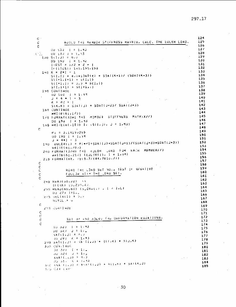
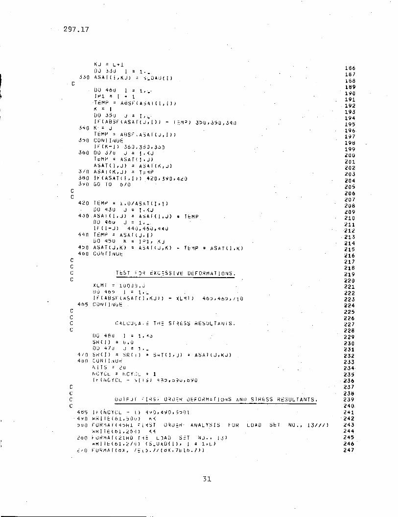
XII. APPENDICES
;'
Appendix A - Program Uilting
The statements which follow are in form compatible with a
CDC 3200 computer but only minor changes would be required for
other machines'. The input and output statements together with
those for the entry and exit may require correction. The listing
does not' conform exactly with the flow chart of Fig. 6 in that it~ ./~/
will cause the deformations and stress resultants to be printed at
~he end of each cycle in the second-order solution. A great
amount of output is not entailed when a limit of 20 cycles is
specified for any problem, and the results at the end of each cycle
are some consolation if convergence has not occurred.
~--------- -
27

297.17
Appendix A Fortran Program
I~PUT ~R_ME 'JO" ~~IT IF NEGATIVE,'
R~AD J)J'JI GJ OkOI'JATES AND TYP~ OF DEfORMATION~
SPECLFICATIU~'DF A~RAY DIMENSIONS,
1~.
,3·.. ·,·4~·
56789
1011
·12··13
;-1415
·16- ..1718·19
·_~O',··
2122· ,23
,24-·,25--26-"
27-i-829
,..aa-.,31-~..
33-~3+
35~.
'37-*
3940-41
-42:'"434445464748--'495051~2
-53:.~.
55-;6·!57
.%-596061
JULY, 196!L.
FRI Tl LABORATORY,'l~HIGH 0~1~E~Slry
HEAn ME~~t:~ :O'JN~CTION DAIA AND PROPERTIES E,I,Ail.
Rt:AD COU-.T Oi:'; .,JOINTS, COUNT"Of- FRAMEMEMBEf.lS.
SECO'~D O~DEH ELASTIC PLANE, FRAMEANAL,YSI'S,
Bt::AM SHEi\R STlr:F'JE55 ASSUMED, IlllfiNHE',
PROGRAM :3202DIMENSION AI24,J6), SI36.36), 5A1(36,24)DHI ENSIU N ASAl( ~ 4 , 25 ), SDAT ( 48 ), DE LT A( 24 )DIMENSION EUL~~llj), S~Ui\DI3U), SR(45)DIM~NSION CURO(lO,2), ~CJN(1~,4), JfYPE(10,3)DIMENSIUN SCQR(lU,2) .
DO ') 5 J = t, J :H~5 R~Au(6U,56) ICJROlI,JI, J = 1,2I,(JIYPFll,J), J = 1,3)"6 FURMATUF1\).5.315)
't 0 RI:: AD( 0 (J , !jO ) J (; I , N~' .:.JO FiJRMAT(215)
1'12 = 2 * NMMS = S * N:'"
DO ';)7 I = 1,\1"1J l .:; 'till - .sK = Jj + :3
') 7 Ri:: A1) ( ,., (I , "d) ('1 :; 0 :~i I , J I, J = 1, 4 ), (~DA1 IN), N = J 1 , K )~H FORMArI4I!j,~;lO.51
l = LJDU 61 I:: 1,J::TDU 01 J:: 1,.)L = L + JTY~EII'J)
60 FORMAfllFiO.j)01 CONlI!'lOt:
NGyel = lJDIY ':>9 I:: 1, j: f
-~OREAD(6U,20) JJ20 FORMAT(l~)
IF (JJ.) J 0, 4u , .. 030 SlOP
cccC
ccCc
cccc
cccc
ccccccccc'c
-cccc
28

297.17
IcCCC
DO ~9 J = 1,2':)9 SCORI!,JI ::: C()~D(I,J)
BUILD TH5 srArrC5~MATRIX A
611 NJ .:; \)NK ::: II006131A:::1.\;.DO 613 !J:::l.""-
613 -AI I A , IJ ) =0 • i.iD() 09 J:: 1, J:rDiJ 68 M= 1 ,~.~
NA .;: NJ-. IF(-J-MCui~I"','ll) b3,62,6:3
62 JF = MCONI~,2)
M-J ::: - MCLlN{ '1 • 3)Mf = MCON ( 'i. 4)GO 10 65
63 IfIJ-MCQN(~,2» 69,64,63b4JF.:; MCONP'1,11
MJ ::: I'1COI~ c." 4)MF-::: i1 C0 r~ ( M, 3 i
65 X ::: CORDIJF,l) - cJRDlj,l)Y-~-CURDIJF,2) - CJRDlj,2)DIST ::: S~RT~(X.X + y.v)oS-YoN· .. YI l) 1STCSN ::: X/OISlNN--,"--·2" NM+.,.IF(JTYPEIJ,l» 6/,07~S6
"6 --NA--:::,--NA-- +-1A(NA,HJ) ::: SY~/DIST
AI NA-, MF·)··:·sn/U 1STAlNA,NN) -=·-CS~
07 IF(JTYPE(J,2» 691,691,5R1- 6 ci 1 NA ::: !'J A + 1.
AINA,MJ) = -C5~/0iST
AINA,Hfl ::: -aS~/Di5r
A l NA , i~ N) ::: - S Y' \j
IF(JTYPElJ,3» 6b2,662~692
NA :: i'JA + 1A(NA,''1J) ::: loUIF(NA - NK) j9,6b,69JNK ::: ;-JACON r! f-WI:NJ :: i'~K
CON r I 1~IF:
I t (i~ CYCL ) .) 40 , I) y j , ;2 9 UC(J N I I i~ Ut:
PRINf TITLES A~U THE STATICS MATRiX (Al.
wRI r t: 16 1 , 7 iJ ) J JFORMATI4/Hlr~~ E~A5TIC S5COND ORDER ANALYSIS OF FRAME NO., 13//11WIHIEI61,tlU)FORMAII 21HUTH~ STATlis MATRIXII)DU 90 i = 1,:.-WRITEI61,10J) I, IAll,j), J = 1,M~)
FORMArI4HO~O~,IS,lX, 151547/l~X, lE16.7»
626364656667
-68
6971171l2.73747576 .7778798081
-- 82838485868788···89
- 90..·9192-9'39495
·969798
- 99100101102103104-1051061071081091l0-_c
111112113114115116117
--ti8119121}121
-122123
29
297.17
c "
c
cC 801LU T~~ ~~~~~ri ~TI~rNESS MAIRIX, CALC. THE ~UlEH LOAD.C
12-412512612112l:)12913013113213313413513613713813914014114214314414514614/14814915015115215315415515615715815916016116216316416516616716816917017117217317417~
176177178179180181182183184185
RcA!) r-t~ LJAD SeT ~O., 1E:ST II' iIIFliAllVEFULLJW" II -t 1M:: _GAll 51: 1.
1 '/ 0
2uO
210CCCCC
~'!O
~ ') n
/.:J':>
fJ,j :> v J I = 1.. '\ j
LJLJ :>iJ,J J = 1,_SA r ( I , J) ;: 1.1. J
jIj ~ 9) K = 1. '" S2 '; I) ;; A 1 \I • J) =-jA r ( I , J ) '+ :; I I ,K) II~ ( J • K )
j u:J i~ U"\I , I ,,~ U t::
:),) ,ii" ;: 1 ••IJ U ,) 2 'J ,j - 1,_A:>AI (l,JI - 'J.):.JU ~')l.j f\':: t ,-1.j
,~ '.' " ') A i ( l •. J) _ ~', I~ , I l , J) .. A \ 1 , !\) " S A I (K , J I
,Lil 1;,)~liHJ'
Rr:A!)(?O.~LJ) ,~
1, (,\KI lu,~:)n. d,'H~AU(OU,60) (j.OAuII! , I " l,llLid ~7? i=1,L.IJi::l I Al I) ;: 'J. ')'\I i~ Y CL ," ,j
ccc sr: I J J ~ \II) ,~)LV '= r -l to lJ t: r 0 i< I~ AT 10 I~ ~ l,j UA I I UN S •
C
P I = ,). J. 41 :i ')2 ~ ,
i.Hl l'JU I ;: 1,'.j'1
J = 4*1 - :St: UL EH I 1 I = PI II '" 1.. :; UA i ( J l, SUA T I J +1 1I I SDAf ( J" 3 ) *SUA T ( J +3 ) )
WHIIE(6.L.?llJ)~URMArIS/~O r~~ t:JLEH _UAU FUH ~ACH MEMHEHJ/)wHI1H61.?1;) (t:JL::tHll, 1 = 1,i~M)
~ URM A't" (1) X, I ~ 1 ~ • 7 / ( i:l )( , 7t 1() • I ) 1
Du L),j l = 1.'1,)
'. ,; IJ(J 'L 5 ,) ,) = 'J,'~ 31.:>0 S\I,J) :: 1].1)
DU l~U 1;: 1,'1~
I IE:, T ;: 1/2 .. 2 - I1~(IT~SI I 140.1?8,1'~
140 K = 2*1 - 1SII,I) = 4.0"S)ATI~) .. SJAT(K+l)/ (SDATIK+3»S( 1+1, 1+1) ;: S ( I • [ )5([+1.1) = ll.:J .. ~i(I,i)
5(1,1+1) = :ilj+l.l)1?f) CUiIIIII~tJt:
UlJ loU I·': 1. ~ ,1J=4"1-,~
r< = i1.~ + ISIK,KI " "DATiJ) .. SDATlJ+2)/ SUAIIJ+j)
160 GUNrll~Ui:
wHIIE(61d/o)1/0 FUHMAflS2Hl T~~ M~M3~~ STIFFN~SS M~THjXII)
DO 13iJ 1=1,""IdO WHIIEU)l.lO') I, (:;(1,)1, J = 1,M,,)
30
297.17
c
KJ = L+iDiJ 33J I = 1 ••
330 ASA1(I,KJ) = S~OAU(I)
XLMr = lUQJO.Ji.Jd 40? I = 1,-..I~IABSHASArII,KJ) - l\L"111 46:>,46:',/10
405 CONrINU'=ccC CALCJ~Ai= TH= 5r~ESS RESULTANIS.C
186187188189190191192193194195196197198199200201C02cOJ204205206207208209210211212
- 21;321421521621721821922022122222322422522622722822923023123223323423:>236237238239240241242243244245246247
TcST FJ~ ~XG~SSIVE DEFORMATIONS.
TEMP = 1.0/A5AT(1,IIDO 43U J = I.<J
,ASAIII,JI = ASAII!,J) * TEMPDO 4bLJ J = 1 ••If(I-JI 440,46U,44UTtMP = ASA!(J.{IDO 450 K = 1"'1, KJASATIJ,KI = ASAT(J,K) - TEMP * ASATII,KICONriNUt
DO 400 1=1,.,11"1 = I + 1-T~MP = ABS~IASAI(I,I»)
K = I-DO 35:) J = 1,-..I~IA8SF(ASArIJ~I)1 - r~M~1 35U,3~O,340
K = JTEMP = A8SFIASAlIJ,II)CON TUWt:I~(K-II 360,3dO,360DU .57U J = I.<JTi:OMr = ASAT<I.JIASATI!,JI = ASAT(~,J)
ASAI(K,JI = T,,'1P1~IASAT<I,II) 420,3~0,420
GO TO 070
1J048U 1=1.'1.5SKI!) = u.ODO 4/,1 ,j = 1 ••
4/0 SK(II = SRI I I + S~T(I'JI ~ ASAT(J,KJ)4 b 0 CON r I ,~ ur:
"'ITS = 2uNCYCL = NCY~~ • 1[t" (NCYCL - III i j) ,,~?,D~\J,tl90
4d5 IH;"CYCL - II 4';iQ,4YO,,?Ol4'10 WRITE<61,50UI ~~
~uO rORMATI4?Hl ~j~ST O~U~R ANALYSIS FOR LOAD S~T NO., 131/1)WkllElol,;UH) ~<
200 FDRMAf<21HO T1~ L)AO 5=T NO., IjlWRI IElbl,~/UI (S.UADlI), I = 1,~1
~/O F(;R,'1,\[(IjX, 1::1.:>.1/(dX,7Elt).71)
J-+o
S:>O
JoO
3/0JbO3'i0
CC
420
4·~O
4 'I 0
4~O
400CCCC
ccC 0 u TP j r : I "( S i 0 ~ u:: R DE FOR MA flO i~ 5 AN iJ S IF. ES S RES ULT ANT S •C
31

297.17
5j5
560
CCCC
5/0
cC
.. C
C
c
c
CCCC
~501 ~RITE(61~55021 ~C'CL
~5U2 FORMAT(29HO qE5U~15 AT E,U OF CYC~E NO., 13//1)WRITE(61d52U)
520 FORMAT(22HO F~AME DE~O~MATIONS/II)
WRITE(61,27U) (ASAT(I,~J), I = 1,~1
WRITE(61,530) .530 FORMAT(28HU MJMENTS AT MEMBER ENDSII})
WRITE(61,2/0) (S~(I),I :: 1,M2)WRIIEI61,54iJ)
540 FORMA](31HO AXIAL TE~SIONS IN MEMBERS///)J :: M2 + 1WRITE(61,210) (SRII), J :: J,M3)
COMPARIS:JN 0., P:iRATED DEFORMATIONS •
D050\J I:: 1, :.1
lEST = ABSF(DE~JAII)/1DO.O)
l~iARSFiASAT(l~~J» • 0.OU01) ~60j555,555
CONTINUEI F( A8 SF( [j ELT A( I ) ... ASAT <I , o(.J » ,- TE5 Tl 560 , 560 , 5 I 0CONTINUEGO TO 61U
MODIFY l~E M:iM3E~ STIFFNESS MATRIX BECAUSE OF AXIAL LOADS.
DO 605 I ~ 1,N~
1'121= M21'IRLOAD :: S~I~211/EJL=R(I)
Ii(RlOAD) 390,5BU,5905dO 82 :: PI * SQ~Tr{~LJADI
EZP = EXPF(82)COTH :: (EZ? + l~O)/(=l~ ft l,U)B :: 8212.0DEN:: B * COIrl - 1,0SK = B*(8-CJT~1' B*car~*JOTH)/DEN
CS :: 8*(8 + CJrH - 8.C]TH*CO~H)/DEN
GO TO 600
590 RlOAD :: -1.0 * R~OAD
8 :: (PI/2.01 ~ SQ~TF(R~OADJ
COT = COSF(g)/~INF(8)
DEN:: 1.0 - a~:OT
SK = 8-(8 • cor· 3*COT*:OT)/DENCS = 0*(8 - car + 3*cur*:OT)/U~N
6UO Ell:: SUAT(4.j.3) .SDAT(4*1-21/SDA](4*1)5(2*1.2*1) .:::;« * ::'1!..'$(2*1-1,2*1-11 = S«*~I.
S I 2'" I , 2* 1-1) :: CS .' E,1 '.,S(2*1-1:2*1) = S{2.J,2.1-1)
,6US CONTI NiJf.:DO 006 i :: 1,:-
606 O~LTA(I) :: ASAT(I,(J)
CHANGE: 111: J]I\lT CO ORDINATES.
LCT :: 0DO 6099 J :: 1,JC1DO 0098 I :: 1,3
32
248249250251252253254255256257
·258259260 _.26126226326426'266267268269270271212273274275276277278279280281282283C!84285286287288289290291292 .293
- 294295 '29t>29.1298299300301;S02303304 .
i'305'-3{)~
307308-'309

297.17
(;0 10 645710 ~HITEI61.72D) ~K
J~O FORMAT(?UHO DE:O~M~lIO~ L1MIT EXCtEUEU 8Y LOAU SET~RITE(61.64Ul JJ,<KGO 10 6'l?
6JO
640CCCC
645
6~O
H~VE~T iJ INIIIA_ :0 ORUINAIES. R~8UILD ST~TICS MATRIX.
, :.,.
.110Jll
·312313314··31531.6 317.11.8 ..319320-32132232332432532632}32832933033133233333433533633733833934034134234334434534634734834935035135235335'435535635.7358~
36036;1.36236336436536636/
.368369370371
372373;
NO., 1311t-~375
, -~U,"'
JU·._-;-~.
fOR LOAU SET NO,,·13111)
NO.,I3,13H LOAD StT NO,,13)
CYCLES , 131/ /)
= 1,JCl= 1,2= S';J!i(I,J)
IF CJNVE~GENCE, ~RINT SECOND ORDER RESU~TS.
RE BJILD THE MEM3E~ STIFFNESS MATHIX lSI,
It' (JTYPe:(J, [» 6U9/j,009:3,6097LGT = LCT + 1IF(I -~) 60~i,6098,609i
CORU(J,I) = SC)R(J,I) + DELTA(LCT)CUf\lTINUt:CONIINUEGO TO 611
wRITE(61.62U) KKFORMAT(46HO St:~ONU DRDER. ANALYSISWRlfE(61,26J) KKwRITE(61.27u) (SLO~D(I), I = l'L}WRITE(61.520)WRITEI61,27u) (ASAT(l,~J), = 1,L)WRlTE(61,53u)WR1TE(61,27U) (SRIl), = l,M2)WRIIE(61,:';41)J = M2 + 1WRITE(61.270) (SRII), 1 = J,M3)WRITEI6t.63ul NCY:LFORMAT(32HO ~JM3E~ OF ITERATIONwRlrE(61.640l JJ,~K
FORMAT(2\}HOANA.rSIS CO~P~ETED FRAME
DO 660 I:: 1,~2
IIEST = 1/2~2-!
I~ lITEST) 6jO,660,6601\ = 2* I - 1S(I,I) :: 4.J*~OATI<) II SOAT(K+11 I SUAT(K+3)511+101+1> = S(loI)5(1+1,) :: 0,::) * SCI,!)5(101+1> = 3([+101)CONI I i~UE
wRIIEI61,6:lUl NCf:LFORMAI(48HO,·l;:RJ DIVI5IJN IN ElWATION SOLUIION, CYCLtNO ..13//)~!RITE(61.64U)· JJ,<KGO 10 645wHI1EI61,70U) NilSFORMAT(2~HU ~J. CJNVE~G~NCE IN, 13, 13H IT~RAIIO~S.II)
~'HIIEI61d7'J)
00 18uO I:: 1, M3W~ITEI61,100) I, Ig(!,J), J = l,M3)WRITE(61.64Ul JJ,<K
DO 661DO b61 JCLlRU(I,J)f\JCYCL = -1GO TO 611
tNU.- 33.
610620
660
661
690"700
6/0660
OO\}560<;860':f9
6097
1600
cccc
cccc
c
cCCC
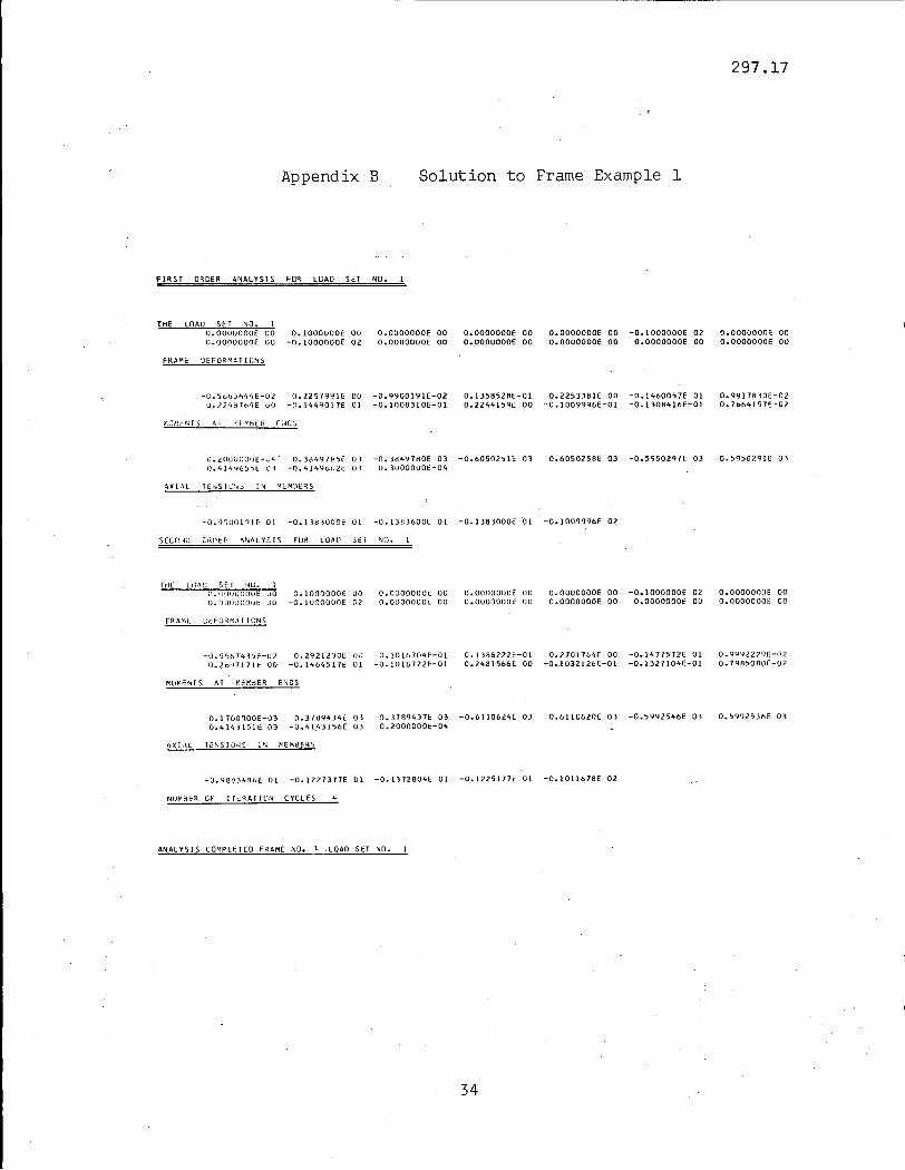
Appendix B
FIRST ORDER ANALYSIS FUR LOAD SET NO.
Solution to Frame Example 1
297.17
THE LOAO SET NO.1O.OOOOOOOE 00 0.1000000E 00O.OOOOOOOE 00 -O.IOOOOOOE 02
FRAME OEFORMATICNS
O.OOOOOOOE 00O.OOOOOOOE 00
O.OOOOOOOE 00O.OOOOOOOE 00
O.OOOOOOOE 00 -0.1000000E 02O.OOOOOOOE 00 o.OOOOOOOE 00
0.00000001' 00O.OOOOOOOE 00
-C.jb~3h44E-02 0.2257991E 00 -O.9900191E-02O.l2407o<J( 00 -O.1449017E 01 -O.l008310E-Ol
0.135B528E-01 0.22;338IE 00 -0.14600;7E 010.2244159" 00 -0.1009996E-Ol -0.130B416E-Ol
0.99178]OE-020.76641571:-02
J.2(lOUOUOE-U4 O.38497~~E 03 -O.38491ROE 03 -O.60502~lE 0]U.41,!t'i65,,>e O-i -O.4149b/,2t Oi U.10000001::-04
A,Xl-\l TE:'>lSIL;'<~ 1\1 ;.o\EM:.\EQ,S
0.6050258E 03 -0.5950297< 03 0.5950791E 0]
-O.OgOOloIE 01 -O.13B.lOOOE 01 -O.l.lA3600E 01 -00138]OOOE 01 -001009996E 02
S(cr~~i; CH!lt:ft "Nt\lY~IS FUK LOAD Sfl ('1D.
friC: lilA!.,; Sf: I !'-'U. 1u.r,OfJGooot: DO O.lOOOOOOi: uou.OtlO'JOOut 00 -O.lOOOOOOE 02
ll.OOOOOOOE 00O.OOOQOOOE 00
o. OOOQOOOE 00O.OOOOQnut: 00
O.OOOOOOOE 00 -0.1000000E 02O.OOOOOODE 00 O.OOOOOOOE 00
o. DOOOOOOE 00O.DoaDOUOE 00
-~"j.:l56 743')1.:-0 l 0.7.9212·10E \)J -O.lOl&704E-C)l 0.1 J86272E-Ol O.2101764f 00 -0.147/572E 01 0.99922791'-07O.2b'H171t:. 00 -O.1464517t 01 -O.101811·2f-Ol 0.2481566E 00 -0.1032126E-Ol -0.1327104E-Ol o. 7q8~OAU[-02
f'l,UMr:~TS AT ~d:M:jER ENDS
0.1700000E-03 O.31tJ9434E 03 -D.3789437E 03 -0.6110624E 03 0.6110620E 03 -0.5992546E 03 o. ~9ql5 3hE 030.414-i 151 t: 0] -O.4143156E 03 O.2000000t:-04
AXI,\l Ti::N$ I l)'~S I ~ MEM~ERS
-0.98"34~6E 01 -001227377E 01 -0.1172804E 01 -0.1225177E 01 -0.1011678E 02
NUf'll::ll:fl CF ITt:RATICN CYCLES
ANALYSIS COMPLETED FRAME NO. I LOAO SET NO.
34

297.17
Appendix C Solution to Frame Example 2
FIRST OROER ANALYSIS FOR LOAIl SET NO.
THE LOAO SET NO. 50.8000000E 02 -0.4800000E 03 O.OOOOOOOE 00 O.OOOOOOOE 00 -0.4800000E 03 O.OOOOOOOE 00 O.OOOOOOOE 00
-0.4800000E 03 O.OOOOOOOE 00 O.OOOOOOOE 00 -0.4800000E 03 O.OOOOOOOE 00 O.OOOOOOOE 00 -0.4800000E 03O.OOOOOOOE 00 O.OOOOOOOE 00 -0.4800000E 03 O.OOOOOOOE 00 O.OOOOOOOE 00 -0.4800000E 03 O.OOOOOOOE 00O.OOOOOOOE 00 -0.4800000E 03 o.OOOOOOOE 00
FRAME DEFORMATIONS
. 0.944319bE 01-0.11I0289E 01
0.1I8bl73E-01O.l123119E 01
-0.l235885E 010.l2482b2E-010.4302b03E Ol
-0.55I1b08E 00
0.1713b83E-020.1018329E Ol
-0.964l530E 00O.l053151E-01
0.941310bE 01-0.12J8068E 01
O.l18853lf-Ol
-0.137340IE 010.l239062E-Ol0.1123136E 01
0.1543234E-020.43025l9E 01
-0.4925535E 00
0.10185b5EOl-0.8623411E 00
0.1053464E-Ol
MOMENTS'·' AT MEM8ER ENDS
0.323b951E 04 0.32I1b17E 04 0.53825b5E 04 0.53b8921E 04 0.5102bl1E 04 0.5105555E 04 0.51D2443E 040.5l01938E 04 -0.323b9bOE 04 -0.2554009E 04 -0.3211b14E 04 -0.2511488E 04 -0.282855bE 04 -0.2916613E 04
':'0.285l429E 04 -0.2923194E 04 -0.2186053E 04 -O.297b9blE 04 -0.218l158E 04 -0.2915b25E 04 -0.2l25480E 04~O~ 3b34128E 04 -0.212b312E 04 -0.3634520E 04
AXIAL TENSIONS IN MEM8ERS
-D.3918100E 02 -0.3l85000E 00 0.l241000E 00 -0.2390000E-Ol -0.4620811E 03 -0.4919122E 03 -0.9l2220bE 03.-0.1001111E 04 -0.l360532E 04 -0.l5194blE 04 -0.18l2l8bE 04 -0.20218l2E 04
SECOND ORDER ANALYSIS FOR LOAD' SET NO.
THE LOAD SET NO. 50.8000DOOE 02 -0.4800000E 03 O.OOOOOOOE 00 O.OOOOOOOE 00 -0.4800000E 03 O.OOOOOOOE 00 O.OOOOOOOE 00
-0.4800000E 03 O.OOOOOOOE 00 O.OOOOOOOE 00 -0.4800000E 03 O.OOOOOOOE 00 O.OOOOOOOE 00 -0.4800000E 03
O.OOOOOOOE 00 O.OOOOOOOE 00 -0.4800000E 03 O.OOOOOOOE 00 o.OOOOOOOE DO -0.4800000E 03 O.OOOOOOOE 00
O.OOOOOOOE 00 -0.48000DOE 03 O.OOOOOOOE 00
FRAME DEFORM TI DNS
0.1920b5lE 02-0.lb320b5E Ol
0.25541l3E-Ol0.4312563E ·01
-0.1839013E 010.2019411E-Ol0.l0645:l1E 02
-0.10RS102E 00
0.1055252E-Ol0.1513131E 02
-Ool405299E 010.2666189E-Ol
0.1911122E 02-0.18b3825E 01
0.2546491E-Ol
-0.20824S0E 010.2001802E-OI0.4312l63E 01
0.1035121E-OI0.IOb4285E 02
-0.5929833E 00
Ool513629E 02-0.121283IE 01
0.2b61513E-Ol
MOMENTS AT MEM8ER ENDS
0.4351314E 04 0.4322811E 04, 0.801188IE 04 0.8060b42E 04 0.1229898E 05 Ool228548E 05 0.1288892E 05
0.1289b49E 05 -0.43513uTE 04 -0.3011498E 04 -0.4322810E 04 -0.30S0146E 04 -0.5600314,E 04 -0.4951112E 04
-0.5bI0481E 04 -0.4911026E U4 -0.134 n9SE 04 -0. 7229bQI:)t: 04 -0.130844SE 04 -0.1184891E 04 -0.5b5930IE 04
-0.8310801E 04 -0.:) 7 Ll592E 04 -0.8060182E [)4
AXiAl TENSIUNS IN Mt:,..,l}/2tt$
-0.3929bllE 02 0.16480141:: 01 D.3R5b172f: 01 O.6412101l 00 -De 4 54 7bS8E 03 -0.50304S1E 03 -0.8856843E 03
-0.103033,E 04, -0.129/,)2111: 04 -O.1~17700i::. 04 -0.17056081: 04 -0.2130289E 04
NUM8ER OF ITERAT 101\ CYCLES 12
ANALYSIS COMPLETED fR,\M€ NO.2 LOAD ~ET 1"0.
35

XIII. TABLES AND FIGURES
36
297.17

_-,. ..,...~ .' ...__--...-....; ....--~----~--~~---.------··-~·,_~.-·'_··..,."..·7' - .~-_- .0
TABLE I. DATA INPUT FOR FRAME EXAMPLE 1
Data Format Card No. Remarks
1 IS 1 Frame identification number
6 5 215 2 Count of joints, members
0·0 0'0 0 0 1 2110'5, 315 3 -0·0 300·0 1 1 1 " II 4
100'0 300'0 1 1 1 II " 5. Joint details-200·0 300'0 1 1 1 II " 6
300·0 300·0 1 1 1 II " 7
300'0 0·0 0 0 1 II II 8 -1 :1 1 2 30000'0 100'0 10'0 300'0 US, 4110'S 9
J-2 3 3 4 II II II 100'0 II II 10
3 4 S 6 " II II 100'0 II " 11 Member details
4 S 7 8 II II II 100'0 II II 12
S 6 9 10 II II II 300'0 II II 131 IS 14 Load set identification number
0'0 0'1 0·0 0'0 0·0 -10'0 0'0 rnO's is0·0 -10'0 0·0 0·0 0'0 0·0 0'0 II 16 Load set
-1 IS 17 Load sets complete indicator
-1 " 18 Frames complete indicator

TABLE II. ANALYSIS OF FRAME EXAMPLE 1
l.Nco
Load Unit Verttcal Horizontal 1st Or!ier Sway 2nd Ol"de r Sway Cycles for Critical LoadSet Load Load ronvergence
(kip) (kip) (in_) (in,) (kip)
1 10 0-1 0-2258 0'2921 4 44'04
2 20 0'2 0-4516 0-7629 6 49'01
3 30 0'3 0-6774 1'5470 8 53-37
4 40 0'4 0-9032 3-0404 12 56'90
5 50 0'5 1 '1290 7'2009 26 59' 30

----~---"IIIl._~.......---...s ...-O.....-.......-......,..·.".--....1I'lII.-*'.........IlIIIlIIIl.IIIIIIIQ,.,.,.-.....C~IIIIII¢..IIIIIIS........--~ - -- .-- .. .----,........
TABLE III. ANALYSIS OF FRAME EXAMPLE 2
Load Set Unit Vertical Horizontal 1st Order Sway. 2nd Order Sway Critical LoadLoad Load
(kip) (kip) (ino ) (ino) (kip)/
1 150 25 2°9510 3·4970 961
2 240 40 4·7216 6°3122 952
3 360 60 7°0824 11 °7227 909
4 480 80 9°4432 19·2065 . 944
5 150 12°5 1 °4755 1°6898 1183
6 240 20 2°3608 3°0820 1026
7 360 30 3°5412 5·5832 984
first order curve
second order curveaxial
loadp
FIG 1
297.17
Euler Load- - -/-- - - - - -_::--
/f/
1/
Lateral deflect °lon 6
TRANSVERSELY LOADED STRUT
40

297.17
lateral
stiffness
. W/6
axial load P
\
I... Euler load
!
I~.iI,~
i
FIG 2 STIFFNESS - AXIAL LOAD VARIATION
41

(c) FORCES ON JOINTS
(b) FORCES ON A MEMBER
(a) TYPICAL MEMBER CONFIGURATION
~' TN,)-)Ms
'~VN
FIG 3 MEMBER AND JOINT EOUILIBRIUM
42

.297.17
next member
No
Find joint at other end of membercompute length. Sine. cose etc.
No
No
No
member
joint
43

297.17
MAB fT
~ B1) T9( )
tv MBA
r-UT--1A
~AB ----
. FIG 5 MEMBER FORCES J DEFORMATIONS
44

& SU ..P
OUTPUT ERRORDESCRIPTIONS
REBUILD STATICS MATRIX
No
Yes
LOAD SET NUMBER
READ LOAD SET
OUTPUT FIRST ORDERRESULTS
CALC.STRESS RESULTANTS
SOLVE DEFORMATIONEQUATIONS. TEST FORLARGE DEFORMATIONS?ZERO DIVISION?
ANDMATRIX
+
OF JOINTSOF MEMBERS
BUILD THE MEMBERSTIFFNESS MATRIXAND CALCULATE EULERLOADS
FIG.6 FLO!! CHART FOR SECOND ORDER ELASTIC ANALYSIS

297.17
x-co~d y-cordII
CORD (I,J) ,and
SCOR( I,J)
( P) I (P)x p Iyp
- "
JCT I JCT,
• >-2• >=3
(degree of freedom)x y e
I . I
I IJTYPE (I,J)
I I1 I 1 I 1
I I
•!En ! In : An: Ln l
SDAT (I))
4NM
LSLOAD(I )
1......- (
)-•
joint joint end end
(N)
I T II
I MCON(I,J) IP I Q R I S
(as in fig 3)
I II I
JCT =joint count
NM = member count
'L = rrJTYPE (I,J)
NM •• ~) 4
FIG 7 DATA INPUT MATRICES
46

297.17
. 3NM 3NM••-----------:.....:.....:.:-4-) ••------'----=...:....:.:....:.~>=
L
•
A (I,J)
IIIIIIII
)L
,I
X XII
X X I S{\,J)I .I
,
(f lexure)~----- x
(extens 'Ion) xx
x
•3NM
1------ ---
.A---,-------~)NM3NM
SAT(I,J) III
ASAT (I,J) II
. III
EULER (I)
L
. DE.LTA(I)
.... --7-). 3NM
ISR(I)
FIGS GENERATED
47
MATRICES

297.17
M2 M3 M4
@~~@~G2 91 = 100 in4
A = 10 in2
E =30000ksi M1
1
®
M5
o
@identificat·lon system
(cD 'FRAME EXAMPLE 1.
1 @ 11 M1 2( @M5~ ~M6121
+12
@ 13 M2 41 @M7~ ~M812'
+ @ 15 M3 6( @M9~ ~Ml012
1
+ ® 17 M4 8J@M11~ ~M1212
1
1 @ @30
1----1I..
c
~ 18x75'UB.55 Vt
a~ 18x7-5 UB.60 VtCD
u::)
a~
xt 18x75UB.60 Vta
~
f-.-x
'I. 'I II/II
VI 'H T 18x75UB.55~
FIG 9(b) FRAME EXAMPLE 2.
DEMONSTRATION EXAMPLES
48

297.17
50
V =100 H
second order
beam sway (in)1 2 3 4
V(kip)
~ first order
40,"
~
I 30~
tV V·--.l:4-. 0
If·f
FIG 10 LOAD-SWAY CURVES FOR FRAME 1.
49

297.17
v V
H + +--+ ~---:_--:.._-
70
theor.
'" solution
""V( kip)30 40
v = 100 H
20I
J::L(kiP/ in)oH
10
·1
·3
·2
o
FIG 11 STIFFNESS-LOAD CURVE J FRAME 1
50

297.17
-800
second orde r
top floor sway (in)4 8 12 16 20,
v (kip)
00
600
I
FIG 12 LOAD-SWAY CURVES FOR FR,AME-2.-
51

;6,
i H.. ,', (I... · J' ), ~ 'r:xln"ln:. bH ,.~.l •
v =12· H
297.17
v VH t, ~-r~,----i
l ,;
t
\,\\
V (ki.p'~:
2 0, 4QQ; 6.0: . 800, 1000;
52

1.
2.
3.
4.
6.
7.
8.
9.
10.
297.17
XIV. REFERENCES
Beedle, L. S.PLASTIC DESIGN OF STEEL FRAMES, John Wiley,New York (1958)
Horne, M. R.INSTABILITY AND THE PLASTIC THEORY OF STRUCTURES,Trans. of Eng. Instit. of Canada, Vol. 4, No.2( 1960)
Vickery, B.' J .THE INFLUENCE OF DEFORMATIONS AND STRAIN HARDENINGON THE COLLAPSE LOAD OF RIGID FRAME STEELSTRUCTURES, Civil Eng. Trans., Instit. of Engrs.Aust., Sept. (1961)
Merchant, W. and othersTHE BEHAVIOR OF UNCLAD FRAMES., Proc. 50th Anniv.Conf. Instit. Struct. Eng. London (1958)
Wang, C. K.GENERAL COMPUTER PROGRAM FOR LIMIT ANALYSIS,Journal of Str. Division, ASCE, ST6, December(1963 )
Harrison, H. B.THE ELASTIC-PLASTIC ANALYSIS OF PLANE FLEXURALFRAMES, Lehigh University, Fritz Eng. Lab.Report No. 297.16, July (1965)
Lu, L. W.A SURVEY OF LITERATURE ON THE STABILITY OF FRAMES,Welding Research Council Bull. -No. 81, Sept. (1962)
Stevens, L. K. and Schmidt, L. C.DETERMINATION OF ELASTIC CRITICAL LOADS, Jnl. ofStr. Div., ASCE, Vol. 89, No. ST6, Dec. (1963)
Livesley, R. K. and Chandler, D. B.STABILITY FUNCTIONS FOR STRUCTURAL FRAMEWORKS,.Manchester.Univ. Press (1956)
Harrison, H. B..COMPUTER ANALYSIS OF PLANE FRAMES, Lehigh Univ.Fritz Eng. Lab. Report No. 297.15, July (1965)
53.

a
11.
12.
13.
14.
15.
16.
297.17
Livesley, R. K; and Chandler, D. B.STABILITY FUNCTIONS FOR STRUCTURAL FRAMEWORKS,Manchester University Press, (1956)
Bleich, F.BUCKLING STRENGTH OF METAL STRUCTURES, McGrawHill, New York (1952)
McCormick, J. M. and Salvadori, M. G.NUMERICAL METHODS IN FORTRAN, Prentice Hall,New York (1964)
Heyman, J.ON THE ESTIMATION OF DEFLECTIONS IN ELASTICPLASTIC FRAMED STRUCTURES, Proc. of I.C.E.,Vol. 19, May (1961)
Column Research CouncilGUIDE TO DESIGN CRITERIA FOR METAL COMPRESSION,Crosby Lockwood, London, (1960)
Horne, M. R.THE EFFECT OF FINITE DEFORMATIONS IN THE ELASTICSTABILITY OF. PLANE FRAMES, Proc. of Royal Soc.,Vol. 226 A. p. 47, (1961)
54