plastering machine mono-mix fu - bmi-illinois.com · circuit diagram fig. 24: circuit diagram...
TRANSCRIPT

Plastering Machinemono-mix fu
3876
04 –
04/
2003
Operating Instructions
3876
04 –
04/
03
3876
04 –
04/
03
2 mono-mix fu
© 2002 m-tec mathis technik gmbh
Copyright in these operating instructions is owned by m-tec mathis technik gmbh. These operating instructionsare intended for use by installation, operating and maintenance personnel. They contain technical regulationsand drawings which may not be copied, distributed, used for advertising purposes, or communicated to thirdparties either in whole or in part without authorisation.
Technical development:The manufacturer reserves the right to modify technical data without notification in order to reflect the currentstate of technical development. For information regarding the current status, alterations or additions to theseoperating instructions, please contact m-tec.
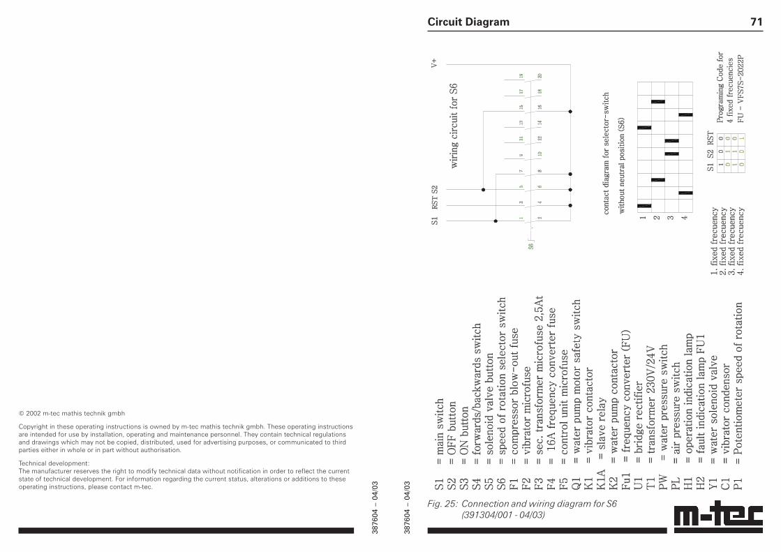
71Circuit Diagram
Fig. 25: Connection and wiring diagram for S6(391304/001 - 04/03)

3876
04 –
04/
03
3876
04 –
04/
03
3Dear Customer,
this machine represents the most up-to-date technology and complies fullywith general standards and EC guidelines. This is indicated by the CE symboland the enclosed Declaration of Conformity in the pocket on the machine.
Before starting the machine for the first time, please removethe Declaration of Conformity from the pocket and keep it ina safe place.
Before commissioning the machine, please complete the form below. This isthe easiest way to familiarize yourself with the most important machine data,and to have them ready at all times without having to refer to the rating plateon the machine. If you wish to contact us at any time, please have the informa-tion on this page ready. The data you require can be found on the machineplate.
Type ________________________________________
Machine no. _________________________________
Year of manufacture _________________________
Power supply _______________________________
Rated current(total)_______________________________________
Date of commissioning ______________________
Application _________________________________
70 mono-mix fu
11 Circuit Diagram
Fig. 24: Circuit diagram mono-mix fu (391304/001 - 04/03)

3876
04 –
04/
03
3876
04 –
04/
03
4 mono-mix fu
1 Safety ........................................................................................................................................... 61.1 Warning Symbols and Hazard Categories .......................................................................... 61.2 General Safety Instructions ................................................................................................. 81.3 Intended Use ..................................................................................................................... 101.4 Target Group ...................................................................................................................... 101.5 Qualified Personnel ........................................................................................................... 111.6 Safety at Work ................................................................................................................... 121.7 Personal Safety Equipment ............................................................................................... 18
2 Description of the Machine ...................................................................................................... 192.1 Method of Function ........................................................................................................... 192.2 Switch Cabinet .................................................................................................................. 212.3 Operating Elements on Switch Cabinet ........................................................................... 222.4 Connections on Switch Cabinet ....................................................................................... 242.5 General Technical Data ...................................................................................................... 252.6 Technical Data Pump Area / Gear Motor .......................................................................... 262.7 Air Supply ........................................................................................................................... 272.8 Water Supply ..................................................................................................................... 282.9 Accessories ....................................................................................................................... 292.10 Symbols on the Machine .................................................................................................. 30
3 Transport / Set-up ..................................................................................................................... 313.1 Transporting the Machine ................................................................................................. 313.2 Setting the Machine up ..................................................................................................... 31
4 Assembly .................................................................................................................................... 324.1 Mounting the Material Trough .......................................................................................... 324.2 Assembling the Screw Pump............................................................................................ 334.3 Assembling Portioning Screw and Motor ........................................................................ 34
5 Start-up ...................................................................................................................................... 355.1 Connecting to Water Supply ............................................................................................. 365.2 Connecting the Water Pump ............................................................................................. 375.3 Water Supply from Drum .................................................................................................. 385.4 Connecting Mortar Hoses ................................................................................................. 395.5 Connecting Spraying Unit (optional) ................................................................................. 415.6 Connecting Fine-Plaster Spraying Unit (optional) ............................................................ 425.7 Mains Power Connection .................................................................................................. 445.8 Rotation Direction of Motor .............................................................................................. 455.9 Installing and Connecting Vibrator (optional) ................................................................... 46
6 Operation ................................................................................................................................... 476.1 Filling the Machine ............................................................................................................ 486.2 Adjusting Material Consistency ........................................................................................ 486.3 Mixing and Pumping .......................................................................................................... 496.4 Spraying with the Spraying Unit ....................................................................................... 506.5 Spraying with the Fine-Plaster Spraying Unit ................................................................... 516.6 Removal of Blockages ....................................................................................................... 526.7 Intervals in Work ................................................................................................................ 536.8 Winter Operation ............................................................................................................... 546.9 Finishing Work ................................................................................................................... 55
69Spare Parts / Accessories
Fig. 23: Spraying units
6051
60Sp
rayi
ng u
nit M
25, 2
00 m
m (7
.87"
) lon
g, s
trai
ght,
with
byp
ass
6051
65Sp
rayi
ng u
nit V
35, 2
00 m
m (7
.87"
) lon
g, s
trai
ght
6051
66Sp
rayi
ng u
nit V
35, 4
00 m
m (1
5.75
") lo
ng, s
trai
ght
6051
67Sp
rayi
ng u
nit V
35, 6
00 m
m (2
3.62
") lo
ng, s
trai
ght
200
400
600
200
400
600
200
400
600
200
400
600
100
200
V35
(V25
)
V35
V35
M25
M25 M25
6051
48Sp
rayi
ng u
nit M
25, 2
00 m
m (7
.87"
) lon
g, b
ent
6051
49Sp
rayi
ng u
nit M
25, 4
00 m
m (1
5.75
") lo
ng, b
ent
6051
50Sp
rayi
ng u
nit M
25, 6
00 m
m (2
3.62
") lo
ng, b
ent
6051
68Sp
rayi
ng u
nit V
35, 2
00 m
m (7
.87"
) lon
g, b
ent
6051
69Sp
rayi
ng u
nit V
35, 4
00 m
m (1
5.75
") lo
ng, b
ent
6051
70Sp
rayi
ng u
nit V
35, 6
00 m
m (2
3.62
") lo
ng, b
ent
6051
45Sp
rayi
ng u
nit M
25, 2
00 m
m (7
.87"
) lon
g, s
trai
ght
6051
46Sp
rayi
ng u
nit M
25, 4
00 m
m (1
5.75
") lo
ng, s
trai
ght
6051
47Sp
rayi
ng u
nit M
25, 6
00 m
m (2
3.62
") lo
ng, s
trai
ght
5451
55Sp
rayi
ng u
nit V
35, 1
00 m
m (3
.94"
) lon
g, s
trai
ght,
with
sto
p va
lve
5451
56Sp
rayi
ng u
nit V
25, 1
00 m
m (3
.94"
) lon
g, s
trai
ght,
with
sto
p va
lve
3876
04 –
04/
03
3876
04 –
04/
03
5Contents
7 Cleaning ..................................................................................................................................... 567.1 Cleaning Mortar Hoses ..................................................................................................... 567.2 Cleaning the Pump Mixing Pipe ........................................................................................ 577.3 Dismantling into Components .......................................................................................... 58
8 Maintenance .............................................................................................................................. 608.1 General Care and Maintenance Work ............................................................................... 608.2 Cleaning Water Filters ....................................................................................................... 618.3 Lubricant Change .............................................................................................................. 62
9 Troubleshooting ........................................................................................................................ 639.1 Faults/Errors at Start-up .................................................................................................... 639.2 Faults/Errors during Operation .......................................................................................... 649.3 Faults in Frequency Inverter .............................................................................................. 66
10 Spare Parts / Accessories ........................................................................................................ 6710.1 Spare Parts ......................................................................................................................... 6710.2 Accessories ....................................................................................................................... 68
11 Circuit Diagram ......................................................................................................................... 70
68 mono-mix fu
10.2 Accessories
The following accessories are available for the mono-mix fu:
• Various spraying units; these are shown onpage 65
• Order no. 600146 test pressure gauge forcompressor, complete
• Order no. 603048 vibrator, 230 V, complete
• Order no. 601283 pressure-testing device completewith coupling M25; the pressure-testing device iscoupled to the pump end piece and tests thedelivery pressure of the screw pump

3876
04 –
04/
03
3876
04 –
04/
03
6 mono-mix fu
1 Safety
1.1 Warning Symbols and Hazard Categories
In these Operating Instructions and according to thestandards defined in ANSI Z535.1-5, the followinghazard categories are used to draw attention topossible dangers which may occur when using themono-mix fu Plastering Machine.
Depending on the seriousness of the hazard, themessages are divided into five hazard categories.
The signal words communicate the level of hazardseriousness.
DANGERindicates an imminently hazardous situationwhich, if not avoided, will result in death orserious injury.
WARNINGindicates a potentially hazardous situation which,if not avoided, could result in death or seriousinjury.
CAUTIONindicates a potentially hazardous situation which,if not avoided, may result in minor or moderateinjuries.
CAUTIONis used without safety alert symbol to indicate apotentially hazardous situation which, if notavoided, may result in property damage.
!
!
!
67Spare Parts / Accessories
10 Spare Parts / Accessories
WARNINGDeath or serious injury or damage to the machineitself or to other property could occur when- using spare parts and accessories not supplied by m-tec mathis technik gmbh or when- modifying the machine.Use only spare parts and accessories supplied bym-tec mathis technik gmbh.The manufacturer will assume no liability for anyaccidents or damage caused by the use of spareparts and accessories of other types or unauthor-ized modification or conversion of the machine.
Please send orders for spare parts tom-tec mathis technik gmbh, Sales Dept.:Tel. Nr.: +49 / 7631 / 709-112 or -216Telefax: +49 / 7631 / 709-116
10.1 Spare Parts
• Spur-wheel back-geared motor (3.0 kW)
• Motor coupling, motor rocker
• Safety grid
• Pump mixing pipe with material troughmixer shaft, pump flange
• Screw pump, rotor, stator
• Pump end piece M35
• Cleaning device
• Switch cabinet 230 V complete
For further spare parts, refer to our spare-partscatalogue.
!

3876
04 –
04/
03
3876
04 –
04/
03
7
NOTICE / ATTENTIONis used without safety alert symbol to indicate apotential situation which, if not avoided, mayresult in an undesirable event or state.
The signal word is accompanied by a pictogramwhich can be of different shape to emphasize thekind of hazard. It is followed by a statement of thehazard, the probable consequence of involvementwith the hazard and how the hazard can be avoided.
Further symbols and signal words used in theseOperating Instructions:
FI CIRCUIT BREAKERThis symbol points out that only FI circuit breakerswith the symbol shown opposite should be used.
ENVIRONMENTAL HAZARDThis symbol points out that environmentalregulations must be observed.
INFORMATION / NOTEThis symbol draws your attention to important oradditional information relevant to the machine ordocumentation.
EYE PROTECTIONThis symbol points out that safety goggles must beworn.The frame of the goggles must comply with thestandard DIN 58211 (part 2) and the safety lenseswith DIN 4647 (sheet 5).
Safety66 mono-mix fu
9.3 Faults in Frequency Inverter
When faults occur in the frequency inverter, the red alarm light on theswitch cabinet lights up. The machine does not start.
Error RemedyOverload protection triggers (consistency Set consistency, fewer hosestoo thick; to many hoses laid out)
Machine switched on and off with main Set double push button “On/Off” to “Off”switch main switch to “0”; then leave machine
switched off for at least 1 minute
To avoid this type of fault, switch themachine on and off remotely or at doublepush button “On/Off”, never at the mainswitch
Frequency inverter overheated, cooler defect Replace or repair cooler on frequency inverter
With alarm signals of any kind, the machine must be switched off at thedouble push button “On/Off” and then the main switch set to “0”.After correcting the fault, wait for at least 1 minute before the frequencyinverter is ready for operation before switching the machine on again.

3876
04 –
04/
03
3876
04 –
04/
03
8 mono-mix fu
1.2 General Safety Instructions
DANGERFollow these safety instructions carefully. Failureto do so may result in increase of risk of accidentor injury. These safety instructions must always beadhered to when transporting, assembling,operating, maintaining or disassembling thismachine. These safety instructions apply to theinstructions throughout this manual, and must beapplied to all facets of the machine’s use,including, but not limited to, transport, assembly,operation, maintenance or disassembly.
The mono-mix fu Plastering Machine has a state-of-the-art design, it is reliable in operation and ithas left the factory in perfect condition. Neverthe-less, it can pose a danger if it has been installedimproperly or contrary to directions (see chapter3), or it is operated by untrained personnel.
In order to protect the machine from damage andenable personnel to operate it properly and safelyevery operator must observe the followinginstructions before starting up the machine:
• Read and understand the Operation and Ser-vice Manual and familiarize with how the machineis operated. The chapter on “Safety” is particularlyimportant.
• Observe the pertinent accident preventionregulations as well as other generally recognizedrules and regulations pertaining to industrial safetyand medical care.
• Ensure that any difficulties are resolvedbefore starting up the machine (seemanufacturer’s address on the back of the cover).
!
65
Error Cause RemedyMotor-protection switch Intake filter clogged, Clean intake filter or replace iton compressor triggers compressor heats up
Hose-pressure gauge Mortar hose kinked or Lay mortar hose as straight asindicates high pressure blocked possible; remove blockage
Material too thick Set consistency thinner
Hose too long Shorten mortar hose
Air nozzle clogged Remove air nozzle on spray unitand clean
Machine switches off Safety valve on compressor Release safety valveduring spraying does not close
Machine cannot be Safety valve on compressor Set valve to 3.2 - 3.5 barswitched on remotely set too low (46.4 - 50.75 psi)
Air-pressure monitor set Set air-pressure monitor to 1.8 bartoo high (26.1 psi) switch-off pressure
Compressor generates too Check air filter, check membrane andlittle air valve plate and replace if necessary.
Troubleshooting

3876
04 –
04/
03
3876
04 –
04/
03
9
The Operation and Service Manual must always bekept in the specially designed pocket on themachine, so that it will be accessible to allmachine operators at all times. All personneloperating or servicing the machine must be toldwhere to find this Manual.
Modifications of the machine are not permitted. Allreplacement parts, accessories and lubricantsmust be furnished by m-tec mathis technik gmbh.The use of unauthorized parts, accessories orlubricants may result in death or serious injury,may cause damage to the machine and will nullifyall liability on the part of the manufacturer forresultant damage.
Wear proper personal protective equipment,including, but not limited to, eye and hearingprotection at all times while operating machinery.Keep hands, feet, hair and clothing away from allmoving parts of the motor to prevent risk ofserious injury. Avoid wearing loose-fitting clothingor jewelry when near the motor, and secure longhair in order to keep it away from moving parts.
This machine must be operated in compliancewith all applicable federal, state and local laws,regulations, and ordinances at all times. Thisincludes, but is not limited to, the requirements ofTITLE 29 of the CODE OF FEDERAL REGULATIONS,PART 1926 (29 CFR 1926). Failure to operate thismachinery in compliance with all applicable laws,regulations, and ordinances may result in death orserious injury.
Safety64 mono-mix fu
9.2 Faults/Errors during Operation
Error Cause RemedyMotor does not start Screw pump stuck Using selector switch “forward/
reverse”, allow the pump to run backand forward for a short time
Frequency-inverter fault (see page 66)
Mortar too thick Too little water Check water infeed,Open fine-control valve further
Mortar too thin Too much water Close fine-control valve further
Uneven mortar consistency Water filter in press. reducer Clean water filtersor inlet clogged
Material accumulation Clean dirty partson mixing shaft or pipe
Mixing shaft worn Replace mixing shaft
Pump end piece dirty Clean pump end piece
Rotor and stator worn Replace rotor and stator
Impossible to set correct Filter in pressure Remove and clean filterwater quantity reducer blocked
Pressure reducer set to Set pressure reducer tolow 2 bars (29 psi) switch-off pressure
Water inlet on mixing Remove water hose with GEKApipe blocked coupling and clean inlet
pipe
Water-inlet filter clogged Remove and clean filter
Machine switches off Water supply fault Check water supply andrestore
Motor-protection switch Material too thick Set material consistencytriggers (Press switch thinnerin before repairing fault) Screw pump too tight Loosen screw pump slightly
Screw pump stuck Allow pump to run back and forwardonce or twice, replace if necessary;
Pump end piece clogged Clean pump end piece

3876
04 –
04/
03
3876
04 –
04/
03
10 mono-mix fu
The proper use of this machinery requires that theoperator be in full control of the machinery at alltimes. None of this equipment must be used by anoperator that is under the influence of alcohol ordrugs, including prescription drugs that mayimpair an operator’s ability to safely operate thisequipment. Failure to adhere to this requirementmay result in death or serious injury.
1.3 Intended Use
The correct use of the mono-mix fu consists in mixingand pumping of previously-mixed dry material with amaximum grain size of 3 mm (0.118") such as mortaror ready-mixed lime-gypsum plasters.
DANGERUse of the machine for any other purpose than thatdescribed above, may result in bodily or even fatalinjury, damage to the machine itself or to otherproperty.It may also impair the efficient functioning of themachine.Use of the machine for any other purpose than thatdescribed above is prohibited!
1.4 Target Group
This document is intended for personnel carrying outstart–up, operation and maintenance of the machine.Such personnel must be qualified according tospecifications stated in chapter 1.5.
!
63
9 Troubleshooting
WARNINGTo prevent death or serious injury, damage to themachine itself or to other property, always complywith the safety notes in each section of theseOperating Instructions!This table is not intended to replace the detailedinstructions in the appropriate sections.
Troubleshooting
9.1 Faults/Errors at Start-up
Error Cause RemedyMachine cannot be no mains voltage Check power connection and plugswitched on in if necessary
Check fuses in site power distributor
no water pressure Check water infeed hoses/pipes
Check water-infeed filter
Solenoid valve on water fittingdefective and does not open:replace
Water-inlet pressure Increase pressure of water feedtoo low (min. 2 bar (29 psi)); if necessary use
pressure-increasing pump
Water-pressure monitor Check water press. monitor:wrongly set Switch-on pressure 2.5 bar (36.3 psi);
Switch-off pressure 2.0 bar (29 psi)Use pressure-increasing pumpif necessary
The 4-pole flange Plug control cable for air-pressuresocket in cabinet monitor of spraying unit oris not assigned fine-plaster spraying unit into
4-pole flange socket
!

3876
04 –
04/
03
3876
04 –
04/
03
11Safety
1.5 Qualified Personnel
DANGERStart–up, operation and maintenance of themachine carried out by unqualified personnel, mayresult in bodily or even fatal injury, damage to themachine itself or to other property.Start–up, operation and maintenance of themachine may only be carried out by qualifiedpersonnel.
It is the duty of the operator to ensure thatoperating staff has read and understood theoperating manuel, in particular the chapter"Safety", and that it is sufficiently qualified foroperating the machine.
Qualified persons are those who, through training orexperience, have sufficient knowledge in the field ofmortar-feeding and mortar-spraying machines andwho are sufficiently familiar with legislation regardingsafety, accident prevention, guidelines and generaltechnical procedures to allow them to assess thesafe condition of such machines.
!
62 mono-mix fu
8.3 Lubricant Change
ATTENTIONGear and motor may overheat if overfilled withlubricant.Always respect filling levels and do not mix diffe-rent types of oil and grease.Non-compliance with lubricating instructions willinvalidate the guarantee.
ENVIRONMENTAL HAZARDAlways observe environmental regulations whendisposing of oil, grease or cleaning agents.
The gear motors are ready for operation on deliveryand are maintenance-free up to 8000 hours ofoperation.
ATTENTIONAfter every 8000 hours of operation, the gears mustbe cleaned using a suitable flushing oil and thenchecked.After cleaning, refill with fresh lubricant of asuitable type.As grease charge for the motor, we recommendfluid grease of type Esso S420, quantity 420 cc.
If the recommended type of grease is not available,the following types may also be used:
Aral FDP 00BP Energrease HTOEsso Fibrax EP-370Mobil Mobilplex 44Shell Special Gear Grease H

3876
04 –
04/
03
3876
04 –
04/
03
12 mono-mix fu
1.6 Safety at Work
DANGERWhen disregarding safety regulations, secureoperating conditions are not guaranteed.When transporting, assembling, dismantling,operating, cleaning, and servicing the machine, theapplicable national and international safetyregulations and legislation must always beobserved, even if such regulations and legislationare not explicitly mentioned in these instructions.
DANGERNonobservance of the following safety instructionsand notes will result in damage to the machine orequipment or even in death or serious injury
Always observe the following safety instructions!
• The machine must be used only for its intendedpurpose (see "Intended Use", page 10)!
• Before every shift, the machine must be carefullyinspected by the foreman for obvious signs ofdamage, in particular to electric cables, plugs,couplings, mortar hose and air hose.
• If necessary, the safety of the machines must beverified by a person qualified to make suchinspections. The inspection must however becarried out at least once per year.
• The machine must not be lifted by crane or otherlifting gear, but transported manually. It can bedismantled into its various components for thispurpose (see “Dismantling into Components”,page 58).
!
!
61Maintenance
8.2 Cleaning Water Filters
The water filters in the water fitting must be cleanedevery 4–6 weeks.
• Open pressure reducer with special key andremove filter
• Open water inlet with special key and remove filter
• Clean filters well – if possible with compressed air
• Replace filters and secure with special key
Fig. 22: Removal ofwater filters1 Special key2 Water filter1 2

3876
04 –
04/
03
3876
04 –
04/
03
13
Before dismantling the machine, the followingoperations must be carried out:- the machine must be run until it is empty (see
“Finishing work”, page 55);- the mortar hoses must be de-pressurized
according to instructions and uncoupled (see“Finishing work”, page 55);
- the machine must be switched off at the pushbutton “On/Off” and the main switch set to “0”;
- all electric cables, water and air hoses must beremoved.
• The machine must be positioned in an area whereno objects can fall onto it. If this is not possible,the machine and the area around it must beprotected by a roof.
• The machine must be positioned firmly on a levelsurface. It must be secured to prevent it fromtilting or moving.
• The work area at the switch cabinet and the areaaround the pump unit must be easily accessible.
• The machine must be connected to a regulationsite distributor box with FI automatic circuitbreaker. Before use, the function of the FI circuitbreaker must be tested while the machine isrunning, as the frequency inverter may cause thecircuit breaker to malfunction.
FI CIRCUIT BREAKEROnly FI circuit breakers with the symbol shownopposite should be used. Required fuse:20 A (min.)
Safety60 mono-mix fu
8 Maintenance
WARNINGDanger of electrocution as certain componentsremain live even when the machine is switched off.Before working on electrical components, alwayspull out the power plug.
WARNINGNonobservance of the maintenance and lubricationinstructions could result in damage to the machineor equipment or even in death or serious injury.Always observe the maintenance and lubricationinstructions!m-tec mathis technik gmbh will assume no liabilityfor damage caused by disregarding themaintenance and lubrication instructions.
8.1 General Care and Maintenance Work
• Before every shift, check the machine for signs ofobvious damage, in particular to hose and cableconnections
• Clean material residues off mixing pipe, materialtrough and mixing shaft
• Clean compressor air filter
!

3876
04 –
04/
03
3876
04 –
04/
03
14 mono-mix fu
• Ensure that the safety grid is mounted securely onthe material trough. Do not put your hands into thematerial trough. Do not place objects in thematerial trough.
• We recommend installing a hose-pressure gauge.This allows the pressure in the mortar hoses to bemonitored at all times, increases the safety of theoperating personnel and ensures economicaloperation. A hose-pressure gauge is not suppliedwith the mono-mix fu.
• For safety reasons, use only mortar hoses with apermitted operating overpressure of 40 bars(580.2 psi) and a bursting pressure of at least 120bars (1740.5 psi).
• During operation, the pressure of 20 bars(290.1 psi) must not be exceeded (monitorpressure on hose-pressure gauge).
• If blockages occur, the machine must be switchedoff immediately at the double push button “On/Off”.
• Always de-pressurize mortar hoses before uncoup-ling them.Check the pressure on the hose-pressure gaugebefore opening them. Cover the coupling with atarpaulin. Wear regulation goggles and do not facethe coupling directly, as material may be ejectedforcefully.
• If the machine is switched off by means of thespraying unit (close air valve) or the fine-plasterspraying unit (close stop valve), it is still on standbyand can be switched on by triggering the sprayingunit or the fine-plaster spraying unit. This issignalized by a white lamp lighting up on thedouble push button “On/Off”.
59
Fig. 21: Dismantling into components1 Eccentric lock of motor2 Mixing shaft3 Motor4 Motor plug5 Bolt on motor rocker, secured with cotter pin6 Interior water feed7 Clamping wedge, both sides8 Cotter pin on clamping wedge, both sides9 Screw pump consisting of rotor and stator
Cleaning
1
2
3
4
5
6
7
8
9

3876
04 –
04/
03
3876
04 –
04/
03
15
INFORMATIONFor the sake of simplicity, the following sentence isused in these instructions to refer to the above-mentioned safety note:
If the machine is switched to “standby” it is stillready for operation and can be started remotely atany time. Indication: the white lamp on the “On/Off” button lights up.
• Never point the spraying unit or the fine-plasterspraying unit at persons!
• The Troubleshooting Table is not intended toreplace the detailed instructions in the appropriatesections of these Operating Instructions. Alwayscomply with the safety notes in each section!
• Before working on electrical components, alwayspull out the power plug, as certain componentsremain live even when the machine is switched off.
• Use only spare parts and accessories supplied bym-tec mathis technik gmbh. If spare parts andaccessories of other types are used, m-tec mathistechnik gmbh will assume no liability for damagecaused.
• Modifications to the machine are prohibited. Themanufacturer will assume no liability for damagecaused by unauthorized modification or conversionof the machine.
• To avoid unnecessary loading of the machine andpremature wear to the spiral pump, do not lay outmore mortar hoses than are actually required.
Safety58 mono-mix fu
• Switch machine off at double push button “On/Off”and set main switch to “0”.
• Rinse the pump-end piece with spray nozzle.
7.3 Dismantling into Components
WARNINGTo prevent electrical shock or projection of hosecouplings or mortar the following operations mustbe carried out before dismantling the machine:- it must be run until empty (see “Finishing work”, p. 55);- the mortar hoses must be fully de-pressurized according to instruction and then uncoupled (see “Finishing work”, p. 55);- the machine must be switched off at double push button “On/Off” and the main switch set to “0”;- all electric cables, water and air hoses must be removed.
Remove pump end piece with screw pump:• Remove securing pin of clamping wedges• Release clamping wedges• Remove pump end piece and screw pump
Remove motor and motor rocker from mixing pipe:• Release eccentric lock• Remove cotter pin on securing bolt and pull bolt
out• Remove motor and rocker• Pull mixing shaft out of the mixing pipe
Remove material trough with mixing part:• Release wedge• Pull the material trough forward and out
!

3876
04 –
04/
03
3876
04 –
04/
03
16 mono-mix fu
• For operation, the direction of rotation of the motormust be set to “1=forward”.
• The machine must only be switched on and off atthe double push button “On/Off”, or using thespraying unit or fine-plaster spraying unit. Neveruse the main switch. If the machine is switched offrepeatedly at the main switch, the frequencyconverter may malfunction.
• Do not use the material until the adequate consis-tency has been reached. Catch any material emer-ging beforehand in a bucket and dispose of itcorrectly.
• During intervals in work, remember the time re-quired for the material to set. The material setsmore rapidly at high temperatures. If the interval inwork is longer than 30 minutes, the machine andthe mortar hoses must be emptied beforehand(see “Finishing work”).
• Below freezing temperature, water fittings may bedamaged if allowed to freeze.
• If the machine is being run until empty, do not usethe watery material in the machine.
• Mortar residues removed during cleaning must beproperly disposed of in a regulation waste-rubblecontainer.
• Overfilling the gear unit and motor with lubricantmay cause overheating. Do not mix different typesof oil and grease.
57
7.2 Cleaning the Pump Mixing Pipe
• Pull out the motor plug (fig. 21, 4)
WARNINGMoving parts can crush and cut.Before working on the pump, pull out the motorplug.
• Release the eccentric lock (fig. 21, 1) of the motor• Fold the motor (fig. 21, 3) down• Pull the mixer shaft (fig. 21, 2) out of the mixing
pipe and material trough• Clean the mixer shaft thoroughly• Insert cleaning device into the mixing pipe• Fold motor up again and secure with eccentric lock• Re-insert motor plug and switch machine on at
double push button “On/Off”• Allow the machine to run until the cleaning device
has moved to the bottom• Switch machine off at double push button “On/Off”
and pull out motor plug
WARNINGDanger of electrocution as certain componentsremain live even when the machine is switched off.Before working on electrical components, pull outthe motor plug.
• Release the eccentric lock of the motor and fold itdown
• Remove the cleaning device• Re-install the clean mixing shaft• Fold motor up again and secure with eccentric lock• Re-insert the motor plug and switch machine on at
double push button “On/Off”• Allow the machine to run briefly to ensure that the
screw pump is properly flushed
Cleaning

3876
04 –
04/
03
3876
04 –
04/
03
17
• Always observe environmental regulations whendisposing of oil, grease or cleaning agents.
• After every 8000 hours of operation, the gearsmust be cleaned using a suitable flushing oil andthen checked. After cleaning, refill with freshlubricant of a suitable type.m-tec mathis technik gmbh will assume no liabilityfor damage caused by disregarding themaintenance and lubrication instructions.
Safety56 mono-mix fu
7 Cleaning
ENVIRONMENTAL HAZARDMortar residues removed during cleaning must beproperly disposed of in a regulation waste-rubblecontainer.
7.1 Cleaning Mortar Hoses
• Insert a foam-rubber ball of the correct diameterinto the mortar hose and couple it to the cleaningvalve of the water fitting with the reducing adapterM35/GEKA.
• Open the cleaning valve until the rubber ballemerges at the other end of the hose
• Repeat the process until clean water emerges fromthe hose.
2
1Fig. 20: Water fitting1 Opening lever of cleaning
valve2 Cleaning valve

3876
04 –
04/
03
3876
04 –
04/
03
18 mono-mix fu
1.7 Personal Safety Equipment
WARNINGNonobservance of the following safety instructionscould result in serious injury.
Always observe the following safety instructions!
• The proprietor/operator of the machine mustsupply personal noise-protection equipment forpersonnel using the machine if the noise level atthe place of work exceeds 85 dB (A).
• If the noise level at the place of work exceeds90 dB (A), the use of this equipment by personnelis compulsory.
• Always wear safety goggles when removingblockages and during spraying work.
• The frame of the goggles must comply with thestandard DIN 58211 (part 2) and the safety lenseswith DIN 4647 (sheet 5).
• During spraying work, always wear a safety helmetand safety shoes or boots.
!
55
6.9 Finishing Work
• Allow the machine to run until the mortar trough andhoses are empty
ATTENTIONTo avoid overload of the machine do not usemortar which is too thin.
• Switch machine off at double push button “On/Off”
• Set reverse switch “Motor forwards/reverse” toposition “2 = reverse”
• Switch the machine on at the double push button“On/Off” and allow it to run until the pressure inthe mortar hoses is zero
WARNINGHose couplings or material could be projectedforcefully when opening hose couplings.Make sure that mortar and hoses are fullydepressurized before uncoupling them.Before opening the couplings:- wear regulation goggles,- check pressure on hose-pressure gauge and covercouplings with a tarpaulin.Do not face the coupling directly when opening it.
• Switch machine off at double push button “On/Off”and switch main switch to “0”
• Switch compressor off if necessary
• Clean the machine (see page 56).
Operation
!

3876
04 –
04/
03
3876
04 –
04/
03
19
2 Description of the Machine
2.1 Method of Function
The mixer and pump components of the mono-mix fuare both powered by the same electric motor. Thematerial is mixed to the adequate consistency in themixer section and then pumped out by an eccentricpump.
The machine is fitted with a frequency converterwhich permits continuous adjustment of the motorspeed.
The mono-mix fu can be controlled directly from theswitch cabinet.If a spraying unit is being used, the machine can beswitched on or to “standby” using the air valve.If a fine-plaster spraying unit is being used, themachine can be switched on or to “standby” bymeans of the trigger.
WARNINGNever point the spraying unit at another person!The machine is still ready for operation if switchedto "standby" and can be started remotely andaccidentally at any time causing serious injury.The white lamp on the “On/Off” button lights up instandby mode.
!
Description of the Machine54 mono-mix fu
6.8 Winter Operation
ATTENTIONWater fittings may be damaged if allowed tofreeze.For longer intervals in work, in particular belowfreezing temperature, completely empty the waterfittings after cleaning.
• Switch off water supply
• Remove and empty feeder hose
• Uncouple water hose between water fitting andmixer pipe
• Open draining valves of water fitting (fig. 19)
• Close draining valve before starting machine upagain
Fig. 19: Drainage of valves1 Draining valves on water fitting
1

3876
04 –
04/
03
3876
04 –
04/
03
20 mono-mix fu
Fig. 1: Mono-mix fu,general view from right-hand side1 Switch cabinet (see p. 21)2 Motor or mixer and pump3 Material trough with safety
grid4 Pump mixing pipe5 Machine interior water
connection6 Spiral pump7 Pump end piece8 Compressor
1 2 3
4
5
6
7
8
1
2
Fig. 2: Mono-mix fu,general view from left-hand side1 Water connections
(see page 28)2 Air connections
(see page 27)
53
6.7 Intervals in Work
ATTENTIONMaterial may set inside the machine and hoses.During intervals in work, remember the timerequired for the material to set. It sets more rapidlyat high temperatures.If the interval in work is longer than 30 minutes,the machine and the mortar hoses must beemptied beforehand (see “Finishing work”).
• For intervals in work of more than 10 minutes,switch the machine off at the double push button“On/Off” and switch main switch to “0”!
Intervals in pump operation of less than10 minutes:• Switch the machine off at the double push button
“On/Off”
Intervals of less than 10 minutes when usingspraying unit:• Close air valve on spraying unit; the machine goes
into “standby mode”
Intervals of less than 10 minutes when using fine-plaster spraying unit:• First close the stop valve to the beginning of the
red zone marked on the lever• Close the stop valve entirely when pressure has
dropped to zero in the mortar hoses (check hosepressure gauge).
Operation
3876
04 –
04/
03
3876
04 –
04/
03
21
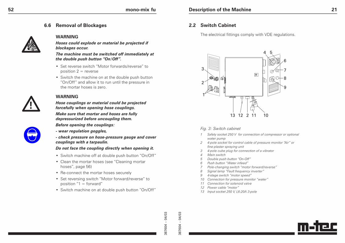
2.2 Switch Cabinet
The electrical fittings comply with VDE regulations.
Description of the Machine
1
2
3
4 5
6
7
8
9
11 1013 12 2
Fig. 3: Switch cabinet1 Safety socket 250 V for connection of compressor or optional
water pump2 4-pole socket for control cable of pressure monitor “Air” or
fine-plaster spraying unit3 4-pole cube plug for connection of a vibrator4 Main switch5 Double push button “On-Off”6 Push button “Water infeed”7 Pole-changing switch “motor forward/reverse”8 Signal lamp “Fault frequency inverter”9 4-stage switch “motor speed”10 Connection for pressure monitor “water”11 Connection for solenoid valve12 Power cable “motor”13 Input socket 250 V, L6-20A 3-pole
52 mono-mix fu
6.6 Removal of Blockages
WARNINGHoses could explode or material be projected ifblockages occur.The machine must be switched off immediately atthe double push button “On/Off”.
• Set reverse switch “Motor forwards/reverse” toposition 2 = reverse
• Switch the machine on at the double push button“On/Off” and allow it to run until the pressure inthe mortar hoses is zero.
WARNINGHose couplings or material could be projectedforcefully when opening hose couplings.Make sure that mortar and hoses are fullydepressurized before uncoupling them.Before opening the couplings:- wear regulation goggles,- check pressure on hose-pressure gauge and covercouplings with a tarpaulin.Do not face the coupling directly when opening it.
• Switch machine off at double push button “On/Off”
• Clean the mortar hoses (see “Cleaning mortarhoses”, page 56)
• Re-connect the mortar hoses securely
• Set reversing switch “Motor forward/reverse” toposition “1 = forward”
• Switch machine on at double push button “On/Off”
!
3876
04 –
04/
03
3876
04 –
04/
03
22 mono-mix fu
2.3 Operating Elements on Switch Cabinet
Main Switch (Fig. 3, 4)In position “0” the machine is disconnected; inposition “1” it is ready for operation.
ATTENTIONNever use the main switch to switch the machineon and off.The frequency converter may malfunction whenswitching the machine off repeatedly using themain switch.The machine must only be switched on and off atthe double push button “On/Off”, or using thespraying unit or fine-plaster spraying unit.
Double Push Button “On/Off” (Fig. 3, 5)The machine can be switched on and off with thedouble push button “On/Off”. Indication: when themachine is switched on and ready for use, the whitesignal lamp on the double push button “On/Off”lights up.
WARNINGNever point the spraying unit at another person!The machine is still on standby when switched offby means of the spraying unit (air valve) or thefine-plaster spraying unit (stop valve).It can be switched on accidentally by triggeringthe spraying unit or the fine-plaster spraying unit.The white lamp on the “On/Off” button lights up instandby mode.
!
51
6.5 Spraying with the Fine-Plaster SprayingUnit
WARNINGNever point the spraying unit at another person!The machine is still ready for operation if switchedto "standby" and can be started remotely andaccidentally at any time causing serious injury.The white lamp on the double “On/Off” buttonlights up in standby mode.
• Ensure that the compressor is switched on: setselector switch to “1” (fig. 17, 1)
• Ensure that the control cable of the fine-plasterspraying unit is plugged in to the switch cabinet(fig. 18, 1)
• Ensure that the air valve on the fine-plasterspraying unit is closed
• Set main switch to “1”
• Switch machine on at double push button “On/Off”
The machine is now ready for operation, i.e. in stand-by mode. However, it only starts when the stop valveon the fine-plaster spraying unit is opened.When the stop valve on the fine-plaster spraying unitis closed again, the machine switches back to stand-by mode.
Operation
!

3876
04 –
04/
03
3876
04 –
04/
03
23
Button “Water Infeed” (Fig. 3, 6)The button “Water infeed” is needed to set thecorrect quantity of water at start-up. As long as it iskept pressed, the solenoid valve also opens when themachine is not switched on with the double pushbutton “On/Off”.
Reversing Switch “Motor Forward/Reverse”(Fig. 3, 7)For normal operation the reversing switch is at“forward”. The position “reverse” is required forreducing the pressure in the mortar hoses (forremoving blockages or when finishing work).
Fault-Signal Lamp ”Frequency Inverter” (Fig. 3, 8)This red lamp lights up to indicate a fault in thefrequency inverter (to correct fault, see section ontroubleshooting).
4-Stage Switch “Motor Speed” (Fig. 3, 9)Using the 4-stage switch “Motor speed”, the machinepower can be selected in 25% steps up to maximum.
Description of the Machine50 mono-mix fu
6.4 Spraying with the Spraying Unit
WARNINGNever point the spraying unit at another person!The machine is still ready for operation if switchedto "standby" and can be started remotely andaccidentally at any time causing serious injury.The white lamp on the double “On/Off” buttonlights up in standby mode.
• Ensure that the compressor is switched on: setselector switch to “1” (fig. 17, 1)
• Ensure that the control cable of the air-pressuremonitor is plugged in to the switch cabinet(fig. 18, 1)
• Ensure that the air valve on the spraying unit isclosed
• Set main switch to “1”
• Switch machine on at double push button “On/Off”
The machine is now ready for operation, i.e. in stand-by mode. However, it only starts when the air valveon the spraying unit is opened.When the air valve is closed again, the machineswitches back to standby mode.
1Fig. 18: Connecting the air-pressure monitor of fine-plasterspraying unit.1 Connection socket for control cableof air-pressure monitor
!

3876
04 –
04/
03
3876
04 –
04/
03
24 mono-mix fu
2.4 Connections on Switch Cabinet
Safety Sockets (Fig. 3, 1)Supply connection for:• the compressor provided (230 V), for use with a
spraying or fine-plaster spraying unit or• an optional water pump (230 V) for low mains
pressures.
Connection Socket 4-pole (Fig. 3, 2)The 4-pole connection socket is for:• connection of control cable of pressure monitor
“air” when the pump is in operation or a sprayingunit is in use;
• connection of control cable for use with fine-plast-er spraying unit.
4-pole Cube Plug (Fig. 3, 3)Connection for optional vibrator.
Connection for Pressure Monitor “Water”(Fig. 3, 10)The water-pressure monitor controls the inlet waterpressure; it must not be disconnected.
Connection “Solenoid Valve” (Fig. 3, 11)The solenoid valve opens and closes the internalwater feed in the machine; it must not bedisconnected.
Supply Cable “Motor” (Fig. 3, 12)The cable for the motor is plugged in on the motorside. For safety reasons, the plug is secured to theframe by a short chain. The chain is too short to allowthe motor to be folded down. If the motor is to befolded down, the plug must first be removed from themotor.
Infeed Socket L6-20 (Fig. 3, 13)The machine is connected to the site powerdistributor via the infeed socket.
49
• If necessary, adjust the flow quantity (fig. 16, 2)with the fine-adjustment valve.
• When the desired consistency has been reached,release the button “water infeed”.
6.3 Mixing and Pumping
When the machine is not being used for spraying,observe the following:
• Ensure that the compressor is switched off(fig. 17, 1)
• Ensure that the control cable of the air-pressuremonitor is plugged into the switch cabinet (fig. 18)
Operation
1 0
1
Fig. 17: Switchingcompressor on/off1 Compressor "On/Off"-switch
• Switch main switch to “1”
• Switch machine on at the double push button“On/Off”
The machine now mixes and pumps material until it isswitched off at the double push button “On/Off”.

3876
04 –
04/
03
3876
04 –
04/
03
25
2.5 General Technical Data
Dimensions (with mixer motor and eccentric screw pump)Length 1430 mm (56.3")Width 670 mm (26.4")Height 1150 mm (45.3")Bag-loading height 980 mm (38.6")
Weight incl. accessories approx. 160 kg (352.74 lb)of which: Accessories 15 kg (33.07 lb)
Mixer unit with material trough incl.eccentric screw pump 75 kg (165.35 lb)Small compressor 15 kg (33.07 lb)Frame with wheels and fittings 55 kg (121.25 lb)
Noise level 76 dB(A); noise-pressure level at 1 m (3.281 ft) distance(free-field measurement during operation)
Description of the Machine48 mono-mix fu
6.1 Filling the Machine
• Fill the material trough with bagged materialthrough the safety grid
6.2 Adjusting Material Consistency
ATTENTIONWrong water quantity will result in improperconsistency of material.Mind proper water infeed and do not use materialuntil sufficient consistency has been achieved.
ENVIRONMENTAL HAZARDCatch any material emerging beforehand in abucket and dispose of it correctly.
• Open the external water supply
• Set the main switch (fig. 16, 1) to “1”
• Keep button “water infeed” (fig. 16, 4) pressed andread the flow quantity on the flow meter (fig. 16, 3)
1
2
34
Fig. 16: Adjustingmaterial consistency1 Main switch2 Fine adjustment valve3 Flow meter4 Button “Water infeed”

3876
04 –
04/
03
3876
04 –
04/
03
26 mono-mix fu
2.6 Technical DataPump Area / Gear Motor
Voltage 230 VFrequency 60 HzPower 3 kWNominal speedl 260 r.p.m.Pump capacity 20 l/min (5.28 gal./min)Pump pressure up to 20 bar (290.1 psi)Pump distance up to 20 m (65.6 ft)Pump height up to 10 m (32.8 ft)max. grain size 3 mm (0.118")max. operating pressure 20 bar (290.1 psi)
DANGERHoses will explode when exceeding hose pressure.During operation, the pressure of 20 bars (290.1psi) must not be exceeded (monitor pressure onhose-pressure gauge).The pumping quantity and height depend on thematerial quality and the condition of the rotor andstator used.
47
6 Operation
WARNINGNonobservance of accident-prevention regulationscould result in damage to the machine orequipment or even in death or serious injury.Always comply with the accident-preventionregulations in force and all generally recognizedsafety regulations.
WARNINGDamage to the machine or parts of it could causepersonal injury, electrocution etc.Before every start-up, inspect the machinecarefully for damage to electric cables, plugs,couplings, mortar and air hoses etc.Any damage must be repaired before starting themachine.
WARNINGMoving parts can crush and cut.Do not put your hands or place objects into thematerial trough.Ensure that the safety grid is mounted securely onthe material trough.
ATTENTIONNever use the main switch to switch the machineon and off.The frequency converter may malfunction whenswitching the machine off repeatedly using themain switch.The machine must only be switched on and off atthe double push button “On/Off”, or using thespraying unit or fine-plaster spraying unit.
Operation
!

3876
04 –
04/
03
3876
04 –
04/
03
27
2.7 Air Supply
The mono-mix fu is fitted with a membrane compres-sor which supplies the compressed air for the spray-ing process. A pressure monitoring device monitorsthe pressure in the air hose. When the pressure gene-rated by the compressor is ≥ 2 bar (29 psi), the machi-ne is switched on from “standby” mode. If the pres-sure in the hose is greater than 2.5 bar (36.3 psi) (e.g.because spraying unit is closed) the pressure mon-itoring device switches the machine back to "standby”.
WARNINGNever point the spraying unit at another person!The machine is still ready for operation if switchedto "standby" and can be started remotely andaccidentally at any time causing serious injury.The white lamp on the “On/Off” button lights up instandby mode.Compressor voltage 230 V
frequency 60 Hzpower 1.1 kWcapacity 250 l/min (66.05 gal. min)max. operating pressure 4 bar (58 psi)
Pressure monitor air starting-up pressure 2.0 bar (29 psi)switch-off pressure 2.5 bar (36.3 psi)
Connections 3/8" -hose with GEKA coupling
Fig. 4: Compressor and air fitting1 Compressor power cable2 Compressor “On/Off” switch3 GEKA-coupling on compressor for
compressed-air hose4 Compressed-air hose 3/8" x 0.9
with cpl.5 Control cable of pressure monitor
(connection on switch cabinet)6 Air-pressure monitor7 GEKA-coupling for air connection
of spraying unit
!
Description of the Machine46 mono-mix fu
5.9 Installing and Connecting Vibrator(optional)
NOTEWhen working with materials such as insulantswith a high polystyrene content, we recommendusing a vibrator (optional).
• Screw the vibrator securely to the mountingsurface provided (fig. 15, 1)
• Connect the vibrator cable to the switch cabinet(fig. 15, 2)
Fig. 15: Installing and connecting vibrator1 Mounting surface2 4-pole cube plug for connection of vibrator cable
1
2

3876
04 –
04/
03
3876
04 –
04/
03
28 mono-mix fu
2.8 Water Supply
The water inlet pressure is controlled by a pressure-monitoring device. If the pressure drops below 2 bar(29 psi), the machine switches off automatically toprevent it from running dry.A built in pump (see fig. 10,1) increases waterpressure when mains water pressure is too low.Pump specifications are:
• Voltage 230 V
• Frequency 60 Hz
• Power 0.3 kW
• Capacity 40 l/min (10.57 gal./min)
A pressure reducer keeps the water inlet pressureduring operation constant at 2 bar (29 psi) to avoidfluctuations in the consistency of the material.
The required water quantity is adjusted manually bymeans of a fine adjustment valve. A flow meter withfloat indicates the flow of water per hour.
Fig. 5: Water fitting1 Water hose 1/2" x 1.25 m complete2 Water inlet3 Ball valve 1/2"4 Water supply tap5 Pressure gauge 0 - 10 bar (0 - 145 psi)6 Pressure monitor 1 - 16 bar (14.5 -
232.1 psi); cut-in pressure 2.5 bar(36.3 psi); cut-off pressure 2.0 bar(29 psi)
7 Pressure reducer 1/2"8 2 draining valves 1/4" AG / IG9 Solenoid valve 24 V10 Pressure gauge 0 - 4 bar (0 - 58 psi)11 Flow meter 300 - 1100 l/h (79.3 -
290.6 gal./h)12 Fine adjustment valve 1/2"
45
5.8 Rotation Direction of Motor
ATTENTIONWrong rotation direction of motor prevents watersupply to mixing pipe.For operation, the direction of rotation of themotor must be set to “1 = forward”.
• The direction of rotation is set with the reversingswitch “Motor forwards/reverse”.Position 1 = forward, position 2 = reverse.
Water is only supplied to the mixing pipe in position“1” (motor forwards). Only then does the solenoidvalve open.
The position “2” (reverse) is required for reducing thepressure in the mortar hoses for removing blockages(see page 52 “Removing blockages”).
Start-up
1
Fig. 14: Rotation direction of motor1 Reversing switch
“Motor forward/reverse”

3876
04 –
04/
03
3876
04 –
04/
03
29
2.9 Accessories
The mono-mix fu is fitted with the following standardaccessories:
• 1 Water pump TM61E
• Eccentric screw pump, type mono-star
• Pump end piece with mortar-hose coupling M 35
• Spraying unit with coupling M 25
• Mortar hose NW 25, 10 m (11 yds.) in length,compl. with coupling V 25/M 25
• 1 air hose 1/2", 11 m (12 yds.) in length, with GEKA-coupling on both ends
• 1 reducing adapter V 35/V 25 turning part
• 1 reducing adapter for cleaning M 35/GEKA
• 1 foam-rubber ball Ø 35 mm (1.38")
• 1 open-end wrench 10 x 13
• 2 ring wrench 19 x 24
• 1 turning tool
• 1 cleaning tool with handle
• 1 wrench for sieve pot
• 1 screwdriver, size 7
• 1 mortar nozzle, hole 12 mm (0.47")
• 1 hose-pressure gauge 0–100 bar (0 - 1450.4 psi)
• 1 cleaning tool
Description of the Machine44 mono-mix fu
5.7 Mains Power Connection
ATTENTIONThe frequency inverter may cause the circuitbreaker to malfunction.Before use, the function of the FI circuit breakermust be tested while the machine is running.
Only FI circuit breakers with the symbol shownopposite should be used.Required fuse: min. 20 A.
Cable and SJ14/3Cable plug types: L6-20A, 3-pole
Fig. 13: Input socket, L6-20A,3-pole1 Input socket
1

3876
04 –
04/
03
3876
04 –
04/
03
30 mono-mix fu
2.10 Symbols on the Machine
Storage for Operating Vibrator connectioninstructions
Selector switch Button water infeedMotor rotationdirection
Reversing switch Compressor connectionMotor speed
Connection for Connection water pumpcontrol cableAir pressure monitor
Connection for con- Connection on machinetrol cable for fine only to site power-distributorplaster-spraying unit with FI circuit breaker
bar
bar
Water-pressure Solenoid-valveconnection gauge
Water supply tap Drain fitting in coldweather
Warning for moving/ Inlet water fittingrotating parts
43
1 2 3 4 5
6
7
Fig. 12: Connecting the fine-plaster spraying unit1 Fine-plaster spraying unit2 Stop valve on fine-plaster spraying unit3 Connection of compressed-air hose with Geka coupling
to the Geka coupling of the fine-plaster spraying unit.4 Socket of control cable on fine-plaster spraying unit5 Connection socket for control cable on switch cabinet6 Connection of compressed-air hose with Geka coupling
at both ends to the Geka coupling of the compressor.7 Connection of mortar hose to fine-plaster spraying unit.
Start-up

3876
04 –
04/
03
3876
04 –
04/
03
31Transport / Set-up
3 Transport / Set-up
3.1 Transporting the Machine
WARNINGTo avoid damage to the machine and personalinjury, do not lift the machine by crane or otherlifting gear.The machine must be transported manually.
The machine can be dismantled into its variouscomponents for this purpose (see section“Dismantling into components”, page 58).
3.2 Setting the Machine up
WARNINGTilting or moving of the machine could causemalfunction or damage to the machine or personalinjury.The machine must be positioned steadily on a levelsurface.The machine must be secured and positioned in anarea where no objects can fall onto it from above.If this is not possible, the machine and the areaaround it must be protected by a roof.The work area at the switch cabinet and the areaaround the pump unit must be easily accessible.
!
!
42 mono-mix fu
5.6 Connecting Fine-Plaster Spraying Unit(optional)
WARNINGNever point the spraying unit at another person!The machine is still ready for operation if switchedto "standby" and can be started remotely andaccidentally at any time causing serious injury.The white lamp on the double “On/Off” buttonlights up in standby mode.
• Connect the compressor power cable to a safetysocket in the switch cabinet (L15-3-pole)
• Connect the long compressed-air hose (Gekacoupling at both ends) to the Geka coupling of thefine-plaster spraying unit (fig. 12, 3) and to theGeka coupling of the compressor (fig. 12, 6)
• Connect the control cable of the fine-plasterspraying unit (fig. 12, 4) to the switch cabinet(fig. 12, 5)
• Connect the mortar hose to the fine-plasterspraying unit (fig. 12, 7)
!

3876
04 –
04/
03
3876
04 –
04/
03
32 mono-mix fu
4 Assembly
4.1 Mounting the Material Trough
• Place the material trough on the mixing pipe• Secure the material trough with the wedge (fig. 6)
Fig. 6: Wedge fastening of mixing pipe1 Wedge
1
41
5.5 Connecting Spraying Unit (optional)
WARNINGNever point the spraying unit at another person!The machine is still ready for operation if switchedto "standby" and can be started remotely andaccidentally at any time causing serious injury.The white lamp on the double “On/Off” buttonlights up in standby mode.
• Connect the power cable of the compressor to asafety socket in the switch cabinet (L15-3-pole)
• Connect the short compressed-air host to thecompressor (fig. 11, 5) and the pressure-monitoringdevice on the air fitting (fig. 11, 7)
• Ensure that the control cable (fig. 11, 6) of the air-pressure monitor is plugged in at the switchcabinet (fig. 11, 9)
• Couple the long compressed-air hose(fig. 11, 4 – Geka coupling both sides) to the Gekacoupling of the spraying unit (fig. 11, 3) and theGEKA coupling of the air fitting (fig. 11, 8)
• Couple the mortar hose to the spraying unit(fig. 11, 13)
Start-up
!

3876
04 –
04/
03
3876
04 –
04/
03
33
4.2 Assembling the Screw Pump
The screw pump consists of a stator with rotor to fit.
• Follow the assembly instructions on the stator(fig. 7, 8)
• Hook a connecting rod (fig. 7, 7) onto one side ofthe pump mixing pipe (fig. 7, 1)
• Place stator with rotor in position (= eccentricpump) on the pump end piece (fig. 7, 9) withouttilting the rotor and stator
• Hook the second connecting rod onto the pumpmixing pipe
• Using the clamping wedges (fig. 7, 2), tighten thescrew pump including the pump end piece andsecure on both sides with cotter pin
If the eccentric pump is not secure enough:• Release the counter nuts of the connecting rods
(fig. 7, 6)• Tighten the tensioning nuts (fig. 7, 5 – both sides)
and re-secure them with the counter nuts
Assembly
Fig. 7: Assembling screwpump1 Pump mixing pipe2 Clamping wedge (both sides)3 Securing pin (both sides)4 Rotor5 Tensioning nut (both sides)6 Counter nut (both sides)7 Connecting rod (both sides)8 Stator9 Pump end piece
40 mono-mix fu
1 2 3 4 5 9
10
11
12
6 7 8
13
Fig. 11: Connecting spraying unit1 Spraying unit2 Air valve on spraying unit3 Air connection with Geka coupling on spraying unit4 Compressed-air hose, with Geka coupling at both ends5 Geka coupling on compressor6 Control cable of air-pressure monitor7 Air-pressure monitor8 Geka coupling on air fitting9 Socket for control cable on air-pressure monitor10 Pump end piece11 Hose-pressure gauge12 Mortar hose coupling on machine side13 Connection coupling for mortar hose on spraying unit

3876
04 –
04/
03
3876
04 –
04/
03
34 mono-mix fu
4.3 Assembling Portioning Screw and Motor
• Insert motor suspension into the holder and securewith bolt; then secure bolt with cotter pin (fig. 8, 6)
• Push portioning screw (fig. 8, 3) into materialtrough so that lower end (fig. 8, 2) enters thebearing provided
• Fold motor over so that the upper end of theportioning screw enters the bearing (fig. 8, 4)
• Fold motor over entirely and secure with eccentriclock (fig. 8, 1)
• Insert motor plug (fig. 8, 5)
Fig. 8: Assembling portioningscrew and motor1 Eccentric lock2 Lower end of portioning screw3 Portioning screw4 Upper end of portioning screw5 Motor plug6 Motor mounting
39
5.4 Connecting Mortar Hoses
DANGERHoses will explode when exceeding hose pressure.Only mortar hoses with a permitted operatingoverpressure of 40 bars (580.2 psi) and a burstingpressure of at least 120 bars (1740.5 psi) must beused.
NOTEWe recommend installing a hose-pressure gauge.This allows the pressure in the mortar hoses to bemonitored at all times and increases the safety ofthe operating personnel.
ATTENTIONDo not lay out more mortar hoses than are actuallyrequired.This avoids unnecessary loading of the machineand premature wear to the spiral pump.
• Connect the hose-pressure gauge (fig. 11, 11) tothe pump end piece (fig. 11, 10)
• Couple the mortar hoses securely to one another
• Couple the mortar hose securely to the pump endpiece
Start-up

3876
04 –
04/
03
3876
04 –
04/
03
35
5 Start-up
WARNINGNonobservance of accident-prevention regulationscould result in damage to the machine orequipment or even in death or serious injury.Always comply with the applicable accident-prevention regulations and all generally recognizedsafety regulations.
WARNINGDamage to the machine or parts of it could causepersonal injury, electrocution etc.Before every start-up, inspect the machine care-fully for damage, in particular to electric cables,plugs, couplings, mortar hose and air hoses.Any damage must be repaired before starting themachine.
WARNINGMoving parts can crush and cut.Do not put your hands into the material trough.Do not place objects in the material trough.Ensure that the safety grid is mounted securely onthe material trough.Disconnect power before servicing.
Start-up
!
38 mono-mix fu
5.3 Water Supply from Drum
INFORMATIONIf water cannot be supplied from a mains pipe, adrum can be used. In this case, a water pump(230 V, optional) is required.
• Place a drum with clean water beside the machine
• Vent the 3/4” water hose
• Insert one end of the hose into the drum (down tothe bottom)
• Ensure that the hose remains at the bottom of thedrum; if necessary, place a stone on the hose
• Connect the other end of the water hose to thepump
• Water-pump connection, see “Connecting waterpump”

3876
04 –
04/
03
3876
04 –
04/
03
36 mono-mix fu
5.1 Connecting to Water Supply
ATTENTIONThe machine will malfunction if water pressure isinsufficient.To ensure trouble-free operation, minimum infeedwater pressure must be constantly 2 bar (29 psi).
• Ensure that the water-draining valves are closed.(fig. 9, 1).
Fig. 9: Water fitting1 Water-draining valves
1
For the exterior water connection, use a 3/4" hosewith a GEKA coupling (not supplied with machine)
• Check that the water hose is free of leaks
• Connect 3/4" water hose with GEKA coupling to thewater inlet (fig. 10, 1) of the water fitting
Make the interior connection between the flow meter(fig. 10, 3) and mixer pipe with the 1/2" water hosewith GEKA coupling (1.25 m (49.2")):
• For cement plasters, use the upper GEKA coupling(fig. 10, 4)
• For gypsum plasters, use the lower GEKA coupling(fig. 10, 5)
• Close the connection not in use with the blindflange
37
Fig. 10: Water connection1 Water pump2 Water inlet in the machine3 Water outlet (e.g. for cleaning)4 GEKA coupling on flow meter5 Water connection for lime gypsum
plasters6 Water connection for gypsum plasters
Start-up
5.2 Connecting the Water Pump
In order to adjuste a too low water pressure in theinlet, a water pump is built in. Water pressure maynot be lower than 2 bar (29 psi).
• Connect water pump and water inlet (fig. 10, 2)with 3/4" water hose and GEKA coupling
• Connect power cable of water pump to a safetysocket in the switch cabinet