plasmonics for solid-state lighting: enhanced excitation ... · original article plasmonics for...
TRANSCRIPT

Plasmonics for solid-state lighting : enhanced excitationand directional emission of highly efficient light sourcesLozano, G.; Louwers, Davy J.; Rodriguez, S.R.K.; Murai, S.; Jansen, O.T.A.; Verschuuren,M.A.; Gómez Rivas, J.Published in:Light-Sciences and Applications
DOI:10.1038/lsa.2013.22
Published: 01/01/2013
Document VersionPublisher’s PDF, also known as Version of Record (includes final page, issue and volume numbers)
Please check the document version of this publication:
• A submitted manuscript is the author's version of the article upon submission and before peer-review. There can be important differencesbetween the submitted version and the official published version of record. People interested in the research are advised to contact theauthor for the final version of the publication, or visit the DOI to the publisher's website.• The final author version and the galley proof are versions of the publication after peer review.• The final published version features the final layout of the paper including the volume, issue and page numbers.
Link to publication
General rightsCopyright and moral rights for the publications made accessible in the public portal are retained by the authors and/or other copyright ownersand it is a condition of accessing publications that users recognise and abide by the legal requirements associated with these rights.
• Users may download and print one copy of any publication from the public portal for the purpose of private study or research. • You may not further distribute the material or use it for any profit-making activity or commercial gain • You may freely distribute the URL identifying the publication in the public portal ?
Take down policyIf you believe that this document breaches copyright please contact us providing details, and we will remove access to the work immediatelyand investigate your claim.
Download date: 04. Sep. 2018
ORIGINAL ARTICLE
Plasmonics for solid-state lighting: enhanced excitationand directional emission of highly efficient light sources
Gabriel Lozano1, Davy J Louwers2, Said RK Rodrıguez1, Shunsuke Murai1,3, Olaf TA Jansen2,Marc A Verschuuren2 and Jaime Gomez Rivas1,4
Light sources based on reliable and energy-efficient light-emitting diodes (LEDs) are instrumental in the development of solid-state
lighting (SSL). Most research efforts in SSL have focused on improving both the intrinsic quantum efficiency (QE) and the stability of
light emitters. For this reason, it is broadly accepted that with the advent of highly efficient (QE close to 1) and stable emitters, the
fundamental research phase of SSL is coming to an end. In this study, we demonstrate a very large improvement in SSL emission (above
70-fold directional enhancement for p-polarized emission and 60-fold enhancement for unpolarized emission) using nanophotonic
structures. This is attained by coupling emitters with very high QE to collective plasmonic resonances in periodic arrays of aluminum
nanoantennas. Our results open a new path for fundamental and applied research in SSL in which plasmonic nanostructures are able to
mold the spectral and angular distribution of the emission with unprecedented precision.
Light: Science & Applications (2013) 2, e66; doi:10.1038/lsa.2013.22; published online 10 May 2013
Keywords: diffraction; fluorescence; LED; nanophotonics; plasmonics
INTRODUCTION
Light-emitting diode (LED) technology is reaching the maturity phase
necessary to replace the more than 100-year-old technology of incan-
descent lamps. It has been said that LED-based sources will light up the
world.1 During the past 10 years, developments in materials have
opened the door for white LEDs, in which several wavelengths com-
bine to mimic the solar spectrum. Following the classification pre-
sented by Pimputkar et al.,1 there are two main routes to achieving
white light using LEDs. The first is to mix the light from individual
electrically driven LEDs that emit the primary colors, i.e., red, green
and blue.2 The current absence of high-efficiency green LEDs limits
the applicability of this approach to the generation of white light.3 The
second and more extended path consists in using a material, usually
known as ‘phosphor’, which absorbs a significant fraction of the light
emitted by an electrically driven ultraviolet or blue LED and re-emits
at a longer wavelength. Mixing the non-absorbed blue light with the
emission provides a spectrum that is perceived as white by the human
eye.4 Most of the research on solid-state lighting (SSL) has, thus far,
focused on the development of light emitters with high internal
quantum efficiency (QE)5 and light extraction mechanisms using
dielectric structures6 to meet the requirements for general illumina-
tion applications. Although SSL sources are efficient, their angular
emission profiles are usually Lambertian. Depending on the applica-
tion, this may result in the need for secondary optics, which are fre-
quently bulky and lossy and degrade the total system efficiency.
Metallic nanoparticles provide unique ways of manipulating light at
length scales smaller than the wavelength. These nanostructures are
known as optical antennas or nanoantennas because of their resonant
behavior at optical frequencies, which can be tuned by varying their
sizes and shapes.7–11 This behavior is achieved through the excitation
of surface plasmons, which are strong optical resonances based on
coherent oscillations of the free electrons in the metal nanoparticles,
driven by the electric field of light.12 In recent years, the field of surface
plasmon polariton optics or plasmonics has shifted from a domain in
which fundamental insights were developed into a discipline that has
become relevant to applications.13 However, to date, no cutting-edge
applications of plasmonic structures are able to compete with state-of-
the-art SSL technologies. One major problem of metals is the inherent
losses associated with their conductivity. In the specific case of light
emission, plasmonic resonances’ ability to enhance the fluorescence of
nearby emitters depends strongly on the efficiency of the emitter and
on its location in respect to the metal/dielectric interface.14 The lower
the QE, the higher the enhancement factor that can be achieved using
plasmonic nanostructures.15–19 For high QE emitters, losses in the
metal lead to a reduction of this efficiency, limiting the enhancement
factor.18,20–22 To minimize this effect, most researchers use noble
metals such as gold or silver, as these metals support localized surface
plasmon resonances and exhibit the lowest damping. A major dis-
advantage is that these materials are expensive and difficult to process.
Moreover, local field enhancements associated with localized surface
1Center for Nanophotonics, FOM Institute AMOLF, c/o Philips Research Laboratories, Eindhoven, The Netherlands; 2Philips Research Laboratories, Eindhoven, The Netherlands;3Department of Material Chemistry, Graduate School of Engineering, Kyoto University, Kyoto, Japan and 4COBRA Research Institute, Eindhoven University of Technology,Eindhoven, The NetherlandsCorrespondence: Dr G Lozano, Center for Nanophotonics, FOM Institute AMOLF, c/o Philips Research Laboratories, High Tech Campus 4, 5656 AE, Eindhoven, The NetherlandsE-mail: [email protected] Professor J Gomez-Rivas, Center for Nanophotonics, FOM Institute AMOLF, c/o Philips Research Laboratories, High Tech Campus 4, 5656 AE, Eindhoven, The NetherlandsE-mail: [email protected]
Received 10 August 2012; revised 20 December 2012; accepted 24 December 2012
Light: Science & Applications (2013) 2, e66; doi:10.1038/lsa.2013.22� 2013 CIOMP. All rights reserved 2047-7538/13
www.nature.com/lsa
plasmon resonances lie on near-field interactions that extend only a
few tens of nanometers away from the metal surface. Therefore, almost
no benefit can be attained using localized resonances when dealing
with highly efficient emitters distributed over large volumes, such as
those that are interesting for use in lighting applications.23,24
In this article, we demonstrate how plasmonics can enhance the
performance of close-to-one QE dyes employed in SSL. In contrast
to the previous studies investigating emitters and metallic structures,
we focus here on improving the emission of already efficient emitters
beyond the limit imposed by near-field effects. We make use of arrays
of metallic nanoantennas that sustain collective plasmonic resonances.
This allows us to shape the angular pattern of the emission, beaming
most of the light into a very narrow angular range in a defined di-
rection. We have investigated the emission characteristics of the plas-
monic array using a laser and a Lambertian-like standard LED as
sources of blue light. A 60-fold unpolarized emission enhancement
compared with a planar layer of dye molecules of similar thicknesses is
achieved in the forward direction at a certain emission energy when
using a collimated laser source. This enhancement reaches a factor of
70 for p-polarized emission. The integrated enhancement over the
emission spectrum of the dye reaches a factor of 14 in the forward
direction. In the case of LED excitation, despite the total enhancement
factor being reduced, the high directionality of the emission remains
unaltered with a 20-fold enhancement in a direction close to the nor-
mal. This directional enhancement is explained as the combination of
an increased efficiency in the excitation of the dye and an enhanced
spatial coherence, which is accomplished by coupling this dye to
extended plasmonic modes in the array, and the subsequent out-coup-
ling to free-space radiation. We have realized large periodic arrays of
aluminum particles using an imprint lithography technique, which
allows the inexpensive and high-quality fabrication of plasmonic
structures over large areas. Nanoplasmonics, therefore, offers a new
platform on which to develop the next generation of SSL devices.
MATERIALS AND METHODS
Sample fabrication
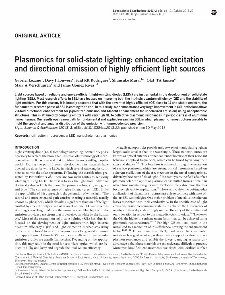
A schematic of the investigated structure is presented in Figure 1a, and
a scanning electron micrograph of the aluminum particles arranged in
a square lattice is displayed in Figure 1b. Aluminum is a non-noble,
inexpensive metal that presents low absorption losses at visible fre-
quencies and has good heat-dissipation properties. Furthermore, it is a
non-toxic, corrosion-resistant and lightweight material. The alumi-
num nanoantenna arrays were fabricated by substrate conformal
imprint lithography in combination with reactive ion etching onto a
fused silica substrate.25 The combination of aluminum and an imprint
lithography technology allows the high-quality fabrication of plasmo-
nic patterns with nanometer resolutions. This technology is ready to
be applied to a large area using standard inexpensive processes, as has
quite recently been demonstrated in the field of photovoltaics.26
Polymers, appropriately doped with dye molecules and emitting in
the visible part of the spectrum, provide stable sources of light for the
large-area SSL. The absorbance and photoluminescence (PL) spectra
of the dye employed in this investigation (Lumogen F Red 305, BASF)
are presented in Figure 1c. This dye is well suited to SSL applications
because of its bright PL in the visible spectrum with a very high QE in a
polymer matrix (,99% at a very low concentration forming a thin
layer, ,85% at 3 wt-%) and good stability. A 10 cm310 cm plasmonic
structure was made of slightly tapered cylindrical aluminum particles,
D5140 nm in diameter and h5150 nm in height, arranged in a
square array with the lattice constant a5400 nm. A d5650 nm-thick
polystyrene layer containing dye molecules at a concentration of
3 wt-% was applied over the array by spin coating.
Optical measurements
The variable angle extinction and photoluminescence directional
enhancement (PLDE) spectra of the luminescent structure were mea-
sured. The extinction is defined as 12T0, with T0 being the zero-order
transmittance normalized by the transmittance through the fused
silica substrate and a polystyrene/dye layer. The PLDE is defined for
each angle of emission as the PL of the dye layer on top of the array of
aluminum particles normalized by the emission of the same layer on
top of the flat substrate. The PLDE is, therefore, the most relevant
quantity in this investigation, representing the improvement to the
light emission introduced by the plasmonic structure. To measure the
optical extinction of the plasmonic structure, a collimated beam of
light from a halogen lamp illuminated the sample, which was rotated
by an angle hin with respect to the normal around the x-axis while
keeping a fiber-coupled spectrometer fixed in the forward direction.
For the PLDE measurements, the red dye was excited at a power level
far below saturation using blue light (2.76 eV, 450 nm) from either a
multimode continuous wave laser 0.01 eV (2 nm) full-width half-
maximum or a high-power blue standard LED (full-width half-
maximum50.1 eV) characterized by a Lambertian-like emission pat-
tern 5 cm behind the sample. The emission was collected using a fiber-
coupled spectrometer, which was rotated by an angle hem with respect
to the normal toward the sample (see Figure 1d for a schematic rep-
resentation of the set-up).
Finite-difference time-domain (FDTD) numerical simulations
A three-dimensional FDTD model was set up with Bloch boundary
conditions on the horizontal edges and PML-absorbing boundaries on
the vertical edges. The dispersion of the metal is fitted using a Drude
model. The incident fields are broadband constant transverse wave-
number pulses. The spectra are obtained using Fourier transforms of
the time-domain near-field responses that are normalized to the incid-
ent pulse.
a
b d
c
h
d=650 nm
zx
a D
emitting
Wavelength (nm)Wavelength (nm)517 443
2.82.42.0
0.8
Nor
m. P
L
Nor
m. A
bsor
banc
e
0.4
0.0Energy (eV)
sample
normal
emitted lightblue light
white light
0.8
0.4
0.0
620
layer
plasmonicarray
substrate
θex θem
θ in
Figure 1 (a) Sketch of the sample consisting of a thick layer of fused silica
(substrate), a periodic array of aluminum particles (plasmonic array) and a layer
of dye molecules embedded in polystyrene (emitting layer). (b) Top view of a
scanning electron micrograph of aluminum particles arranged in an ordered
periodic lattice. Scale bar indicates 500 nm. (c) Normalized photoluminescence
(red curve) and normalized absorbance (black curve) spectra of the dye
(Lumogen F Red 305, BASF). (d) Scheme depicting the different angles involved
in the experiments. PL, photoluminescence.
Plasmonics for solid-state lighting
G Lozano et al
2
Light: Science & Applications doi:10.1038/lsa.2013.22
Lifetime measurements
A series of fluorescent lifetime measurements was conducted using a
streak camera (Hamamatsu 5680) synchronized with a femtosecond
laser (Spectraphysics Tsunami). A pulse-picker and a second har-
monic generator (Spectraphysics 3980) were used to enable the excita-
tion of the dye with 2.76 eV pulses at a 2 MHz repetition rate.
RESULTS AND DISCUSSION
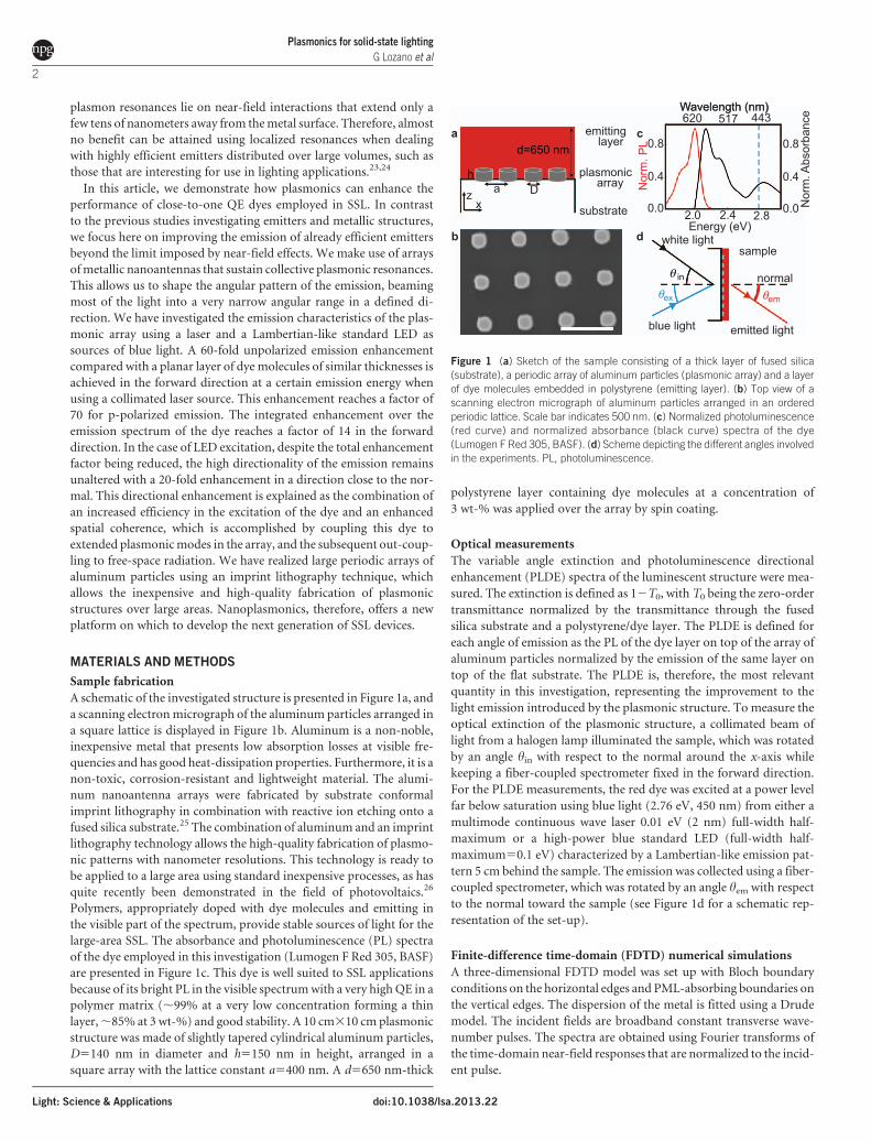
Figure 2a presents the measured p-polarized extinction of the inves-
tigated structure as a function of the energy of the incident radiation
and the angle that forms the incident wave-vector with the normal
toward the sample (hin). The PLDE measurements are displayed as a
function of the photon energy of the p-polarized emitted radiation
and the emission angle hem in Figure 2b. All the features observed in
PLDE are correlated with those shown in the extinction measure-
ments. Most of the dispersive features observed in the experiment
can be associated with electromagnetic surface modes supported by
periodic metallic structures.27 They appear as narrow bands of high
extinction that follow the dispersion of the Rayleigh anomalies, i.e., the
energy at which a diffracted order radiates in the plane of the array;
these bands are known as surface lattice resonances (SLRs).28–33 SLRs
are, therefore, the result of the enhanced radiative coupling of loca-
lized surface plasmon polaritons in the individual particles by means
of in-plane diffracted orders. SLRs can be described as quasi-bounded
surface modes in the array and have a propagation length of several
unit cells.34 From the conservation of the parallel component of the
wave-vector at the surface of the array, we have +kEd~kEi+G, where
+kEd and kEi are the parallel components of the diffracted and inci-
dent wave vectors, respectively; G~ Gx ,Gy
� �~ 2p=að Þp, 2p=að Þq½ � is a
reciprocal lattice vector; and p and q are the pair of integers defining a
diffracted order. Rayleigh anomalies of beams diffracted by the square
array of particles are plotted as colored curves in Figure 2a and 2b.
They correspond to the onset of (61,0) and (0,61) diffracted orders,
calculated assuming that the array is embedded in a homogeneous
medium, with refractive indexes of 1.47 (gray curves), 1.52 (purple
curve) or 1.55 (green curves). These values are obtained by fitting the
Rayleigh anomalies to the maxima in the extinction spectrum, mea-
sured at hin506. In these experiments, the particle array is not homo-
genously surrounded by the same dielectric. The particles are on a
fused silica substrate with a lower refractive index (1.46) than the
polystyrene layer (1.59), which has a finite thickness of 650 nm.
Numerical simulations reveal that the different refractive index layers
surrounding the array and the finite thickness of the polymer layer
modify the distribution of the local field intensities around the par-
ticles (see Supplementary Information). The intensity extends farther
into the substrate for the resonance at 2.11 eV than for the resonances
a 2.2
2.1
2
0 5θ in (deg)
θem (deg)
10
0 5 10
1.9
Ene
rgy
(eV
)
Energy (eV)
PL relative intensity
1.8
2.2
2.1
2
1.9
Ene
rgy
(eV
)
1.8
1.8 1.9 2.0 2.1 2.2
564 564590620653689
590
620
653
689
564
590
620
653
689
1Extinction
Ext
inct
ion
Wavelength (nm)
0
PLDE PLD
E
0.80.8
0.6
0.4
0.4
0.2 0.060
40
60
70
50
40
30
20
10
0
min max
planarplasmonic
30
20
10
0
30
20
10
0
800
600
400
0
0x (nm)
z (n
m)
z (n
m)
200
200-200
800
600
400
0
0x (nm)
200
200-200
20
0
Wavelength (nm
)W
avelength (nm)
b
c
d
g
f
e
(+1,0)
(0,+1)_
(0,+1)
(-1,0)
(-1,0)
(+1,0)
|E0|E |2|2/
_
Figure 2 (a) Extinction of p-polarized light as a function of the photon energy and the angle of incidence hin of a layer of dye deposited on top of the investigated array of
aluminum particles. (b) p-polarized directional emission enhancement as a function of the photon energy and the emission angle hem measured on the same structure
excited with a 2.76 eV continuous wave laser at hex506. Gray, purple and green curves correspond to the Raleigh anomalies calculated for the beams diffracted in a
medium with refractive indexes of 1.47, 1.52 and 1.55, respectively. (c) Extinction and (d) PLDE as a function of photon energy measured at hin506and hem506. (e, f)
Simulated spatial distribution of the near-field intensity enhancement in a plasmonic array of antennas on a substrate covered by a polymer layer. The color plot
indicates the intensity enhancement of the plane intersecting the antennas at y50 in a unit cell of the array. The simulations consider a plane wave incident normal to
the array with a photon energy of (e) 1.85 eV and (f) 2.04 eV. The antenna and the different dielectric interfaces are outlined using gray curves. (g) Digital photographs
taken from the unpolarized emission from the dye layer deposited on top of the plasmonic structure (left) and from the same layer deposited on a dielectric substrate
(right) at hem of ,06. PLDE, photoluminescence directional enhancement.
Plasmonics for solid-state lightingG Lozano et al
3
doi:10.1038/lsa.2013.22 Light: Science & Applications

at 2.04 eV and 2.00 eV, whose field intensities are primarily concen-
trated in the dye-doped layer. The difference in field intensity distri-
bution causes a difference in the effective refractive index of these
modes and the concomitant energy shift. The blue-shift of the
2.11 eV mode is consistent with its higher field intensity in the lower
refractive index substrate compared to the modes observed at 2.04 eV
and 2.00 eV. It should be noted that this multilayer structure can
support index-guided modes coupled to free-space radiation by the
array of nanoparticles and, consequently, with a similar dispersion to
the SLRs. For simplicity, we have limited the analysis of the extinction
and luminescence measurements to SLRs in homogeneous media in
which index-guided modes do not exist.
SLRs can couple very efficiently to radiation because of their hybrid
plasmonic–photonic characters. Excited emitters in the proximity of
the array can decay into SLRs, which radiate into free space, enabling
the control of the spontaneous emission.29,35 We would like to note
that similar results may be attained using dielectrics with tailor-made
polarizability, as suggested by previous theoretical investigations
regarding titania nanoparticles arranged in one-dimensional arrays.36
In particular, the bands of maximum PLDE follow the dispersion of
the SLRs associated with the (21,0) and (0,61) diffractive orders.
Figure 2b shows that a many-fold enhancement of the fluorescence
takes place on the narrow bands between hem506 and hem5106. We
achieve a maximum PLDE of 72 times at hem51.56 and 2.01 eV.
Comparable features and enhancement values can be observed for s-
polarized emission because of the square symmetry of the array (see
Supplementary Information). This remarkable enhancement of the
emission occurs close to the normal with respect to the surface. The
enhanced and directional emission of the emitters, which are already
close to unity efficiency, demonstrates that arrays of nanoparticles can
be integrated into lighting devices as efficient and compact secondary
collimating optics. Moreover, the ability to tune the dispersion of SLRs
by varying the shape and dimensions of the nanoparticles, the lattice
structure and the period of the array opens the possibility of fully
controlling the emission of the different light emitters integrated in
plasmonic-based LEDs. This demonstration of the PLDE of highly
efficient emitters contradicts the idea that plasmonic structures are
detrimental to the performance of devices using high QE emitters
because of inherent Ohmic losses in metals.37–39 To facilitate further
investigation of how the plasmonic array enhances and shapes, the
fluorescence of the emitting layer, cuts of the spectra presented in
Figure 2a and 2b at h506are displayed in Figure 2c and 2d. Two types
of resonances with different line widths can be observed in the mea-
sured extinction spectrum: (i) a broad resonance centered at 1.85 eV,
which is attributed to localized surface plasmons in individual par-
ticles and (ii) three narrow peaks at 2.00 eV, 2.04 eV and 2.11 eV,
associated with collective lattice modes. Note that the luminescence is
significantly enhanced only at these narrow resonances. Specifically,
the solid black curve in Figure 2d depicts three peaks, corresponding to
58-fold, 50-fold and 7-fold PLDEs. It is noteworthy that the localized
character of the broad resonance centered at 1.85 eV merely leads to a
weak PLDE factor of 4.
To further describe the origin of the spectral features associated with
the different plasmonic resonances, in Figure 2e and 2f, we perform
numerical three-dimensional FDTD simulations of the spatial distri-
bution of the total electric field intensity enhancement—i.e., near-field
intensity normalized by the incident intensity—at two different fre-
quencies: 1.85 eV and 2.04 eV, respectively. The simulated extinction
at hin506and the near-field intensity of the resonances at 2.00 eV and
2.11 eV are provided in the Supplementary Information. We consider
a plane wave incident to be normal to the array. A small tapering of the
aluminum particles was included in the model to account for their
actual shapes. The simulation in Figure 2e, which depicts a side view
(see Supplementary Information for a top view) of a unit cell of the
array, indicates that the broad extinction peak corresponds to an in-
plane dipolar resonance. The field is primarily enhanced in the prox-
imity of the particles, as expected for a localized surface plasmon
polariton. A major drawback inherent to the use of localized surface
plasmon resonances to enhance light-matter interactions is that the
emitters need to be accurately positioned with nanometric precision in
the region in which the largest electromagnetic enhancement occurs.17
This characteristic, together with the fact that dye layer extends over a
thickness of 650 nm on top of the particle array, leads to the weak
PLDE associated with the localized surface plasmon resonance. In
contrast, the narrow extinction peak at 2.04 eV corresponds with
the collective plasmonic mode associated to the SLR. The field
enhancement of this resonance, as shown in Figure 2f, extends over
a much larger distance in the space between the nanoantennas,32 lead-
ing to the enhancement of the dye emission from larger volumes. This
enhanced emission from large volumes is critical for real SSL applica-
tions in which a specific fluorescence count rate must be reached.
To present a clear visual effect of the enormous PLDE attained when
using an array of nanoparticles, Figure 2g shows images, taken with a
digital camera, of the unpolarized emission from a dye layer deposited
onto a flat dielectric substrate, labeled ‘planar’, compared with the
emission from a similar layer but coupled to an array of metallic
particles, labeled ‘plasmonic’. The former refers to the common con-
figuration used in LED devices.40 From this point on, we will present
the results for the unpolarized emission, as polarization dependency is
generally undesirable in SSL devices.
The total PLDE is the result of phenomena taking place at the
excitation and emission frequencies of the dye. On the one hand,
the absorption efficiency of the dye can be increased by a resonant
enhancement at the excitation frequency when the system is optically
pumped. On the other hand, in a plasmonic system, the emission is
influenced by the modified local density of the optical states and by the
out-coupling of the emission to free space.41,42 To investigate the
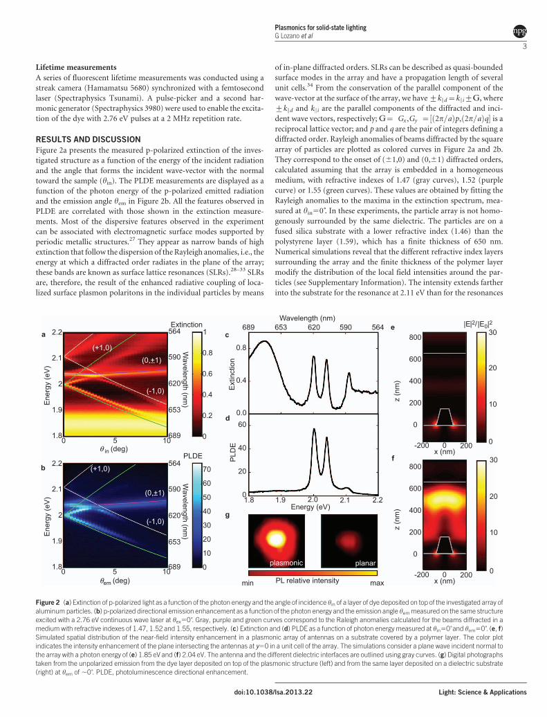
contribution of the resonant pump enhancement, we have measured
the PLDE spectra for unpolarized emission as a function of the excita-
tion angle, fixing the detector at hem5556, i.e., at an angle at which no
plasmonic resonance occurs at the emission frequency. Figure 3a dis-
plays the PLDE integrated between 1.75 eV and 2.15 eV as a function of
hex, showing a ,sixfold overall fluorescence enhancement when the
dye molecules are excited at hex506. This enhancement is halved when
hex is 106. As noted in the Supplementary Information, the relative
contribution of the pump enhancement attained at a different hex
from the PLDE is roughly proportional to how much blue light is
extinct as a function of hin. The large enhancement at normal inci-
dence is attributed to a higher order SLR and, in particular, to that
associated with the (21,1) diffracted order. As discussed below and in
view of the numerical simulations and PL lifetime measurements, this
,sixfold enhancement can primarily be attributed to a resonant
enhancement of the excitation of the dye at the frequency of the pump.
Three-dimensional FDTD simulations of the PLDE were performed
to separate the contribution of the emission from that of the pump.
According to the reciprocity theorem and assuming a set of isotrop-
ically oriented dipoles, the PLDE is obtained as the ratio of the inte-
grated electric near-field intensity in a unit cell, computed in a
structure with and without metallic particles and calculated for a plane
wave illumination along the angle of emission at which the PLDE is
Plasmonics for solid-state lighting
G Lozano et al
4
Light: Science & Applications doi:10.1038/lsa.2013.22
evaluated.43 The results for the unpolarized emission are displayed in
Figure 3b. The number of bands obtained from the simulation, their
spectral positions, the dispersion and the PLDE values are in good
agreement with the measurements. In Figure 3c, we present numerical
simulations that do not consider any resonant enhancement at the
pump frequency, providing a maximum enhancement of ,12 times.
To examine the angular modification of the emission by the plas-
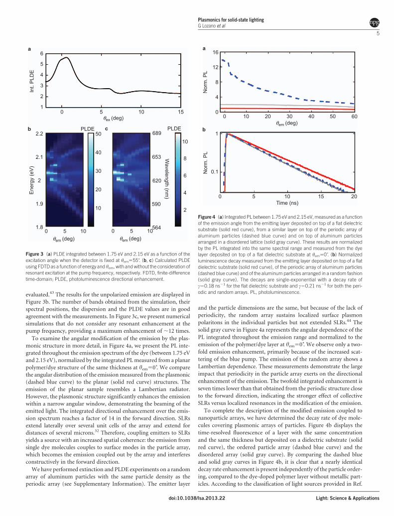
monic structure in more detail, in Figure 4a, we present the PL inte-
grated throughout the emission spectrum of the dye (between 1.75 eV
and 2.15 eV), normalized by the integrated PL measured from a planar
polymer/dye structure of the same thickness at hem506. We compare
the angular distribution of the emission measured from the plasmonic
(dashed blue curve) to the planar (solid red curve) structures. The
emission of the planar sample resembles a Lambertian radiator.
However, the plasmonic structure significantly enhances the emission
within a narrow angular window, demonstrating the beaming of the
emitted light. The integrated directional enhancement over the emis-
sion spectrum reaches a factor of 14 in the forward direction. SLRs
extend laterally over several unit cells of the array and extend for
distances of several microns.32 Therefore, coupling emitters to SLRs
yields a source with an increased spatial coherence: the emission from
single dye molecules couples to surface modes in the particle array,
which becomes the emission coupled out by the array and interferes
constructively in the forward direction.
We have performed extinction and PLDE experiments on a random
array of aluminum particles with the same particle density as the
periodic array (see Supplementary Information). The emitter layer
and the particle dimensions are the same, but because of the lack of
periodicity, the random array sustains localized surface plasmon
polaritons in the individual particles but not extended SLRs.44 The
solid gray curve in Figure 4a represents the angular dependence of the
PL integrated throughout the emission range and normalized to the
emission of the polymer/dye layer at hem506. We observe only a two-
fold emission enhancement, primarily because of the increased scat-
tering of the blue pump. The emission of the random array shows a
Lambertian dependence. These measurements demonstrate the large
impact that periodicity in the particle array exerts on the directional
enhancement of the emission. The twofold integrated enhancement is
seven times lower than that obtained from the periodic structure close
to the forward direction, indicating the stronger effect of collective
SLRs versus localized resonances in the modification of the emission.
To complete the description of the modified emission coupled to
nanoparticle arrays, we have determined the decay rate of dye mole-
cules covering plasmonic arrays of particles. Figure 4b displays the
time-resolved fluorescence of a layer with the same concentration
and the same thickness but deposited on a dielectric substrate (solid
red curve), the ordered particle array (dashed blue curve) and the
disordered array (solid gray curve). By comparing the dashed blue
and solid gray curves in Figure 4b, it is clear that a nearly identical
decay rate enhancement is present independently of the particle order-
ing, compared to the dye-doped polymer layer without metallic part-
icles. According to the classification of light sources provided in Ref.
a
b
12
8
4
16
Nor
m. P
LN
orm
. PL
050403020100 60
1550 10 20
1
Time (ns)
0.1
θem (deg)
Figure 4 (a) Integrated PL between 1.75 eV and 2.15 eV, measured as a function
of the emission angle from the emitting layer deposited on top of a flat dielectric
substrate (solid red curve), from a similar layer on top of the periodic array of
aluminum particles (dashed blue curve) and on top of aluminum particles
arranged in a disordered lattice (solid gray curve). These results are normalized
by the PL integrated into the same spectral range and measured from the dye
layer deposited on top of a flat dielectric substrate at hem506. (b) Normalized
luminescence decay measured from the emitting layer deposited on top of a flat
dielectric substrate (solid red curve), of the periodic array of aluminum particles
(dashed blue curve) and of the aluminum particles arranged in a random fashion
(solid gray curve). The decays are single-exponential with a decay rate of
c50.18 ns21 for the flat dielectric substrate and c50.21 ns21 for both the peri-
odic and random arrays. PL, photoluminescence.
a
b c2.2
2.1
2
1.9
Ene
rgy
(eV
)
1.8
8
6
4
10
2
5
4
3
6
1
lnt.
PLD
E
2
50
40
30
20
10
θem (deg)0 5 10
θem (deg)
θex (deg)
0 5 10
0 5 10 15
564
590
620
653
689
Wavelength (nm
)
PLDEPLDE
Figure 3 (a) PLDE integrated between 1.75 eV and 2.15 eV as a function of the
excitation angle when the detector is fixed at hem5556. (b, c) Calculated PLDE
using FDTD as a function of energy and hem, with and without the consideration of
resonant excitation at the pump frequency, respectively. FDTD, finite-difference
time-domain; PLDE, photoluminescence directional enhancement.
Plasmonics for solid-state lightingG Lozano et al
5
doi:10.1038/lsa.2013.22 Light: Science & Applications
45, the dye molecules employed in our investigation can be considered
as constant power sources because of their very high QE. Constant
power sources are not influenced by a change in the LDOS, and the
total emitted power scales linearly with the total absorbed power. For
this reason, the total decay rate enhancement experimentally observed
may be attributed to a non-radiative decay channel introduced by the
metal rather than by the SLRs in the array. It has been argued that
because the presence of metallic particles near emitters introduces a
non-radiative decay channel,38,39 the primary effect on the high QE
emitters is the reduction of their efficiency.34–36 Therefore, the
observed decay-rate enhancement can be attributed to the quenching
of the emission. This quenching is considered a major drawback in
realistic applications. However, our decay-rate measurements show a
reduction in QE of only 15% but a maximum 60-fold and an inte-
grated 14-fold directional enhancement in the forward emission di-
rection. Based on these results, we infer that the maximum ,60-fold
directional enhancement measured for the unpolarized emission may
be approximately expressed as the product of a factor of ,6 due to
pump enhancement and a factor of ,10 due to emission enhance-
ment.
Having discussed how plasmonic structures can boost the perfor-
mance of a thin layer of luminescent material, we take a step forward
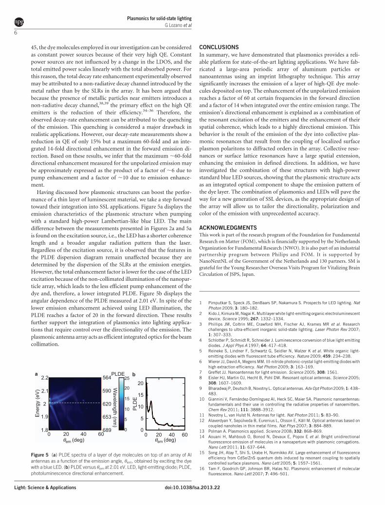
toward their integration into SSL applications. Figure 5a displays the
emission characteristics of the plasmonic structure when pumping
with a standard high-power Lambertian-like blue LED. The main
difference between the measurements presented in Figures 2a and 5a
is found on the excitation source, i.e., the LED has a shorter coherence
length and a broader angular radiation pattern than the laser.
Regardless of the excitation source, it is observed that the features in
the PLDE dispersion diagram remain unaffected because they are
determined by the dispersion of the SLRs at the emission energies.
However, the total enhancement factor is lower for the case of the LED
excitation because of the non-collimated illumination of the nanopar-
ticle array, which leads to the less efficient pump enhancement of the
dye and, therefore, a lower integrated PLDE. Figure 5b displays the
angular dependence of the PLDE measured at 2.01 eV. In spite of the
lower emission enhancement achieved using LED illumination, the
PLDE reaches a factor of 20 in the forward direction. These results
further support the integration of plasmonics into lighting applica-
tions that require control over the directionality of the emission. The
plasmonic antenna array acts as efficient integrated optics for the beam
collimation.
CONCLUSIONS
In summary, we have demonstrated that plasmonics provides a reli-
able platform for state-of-the-art lighting applications. We have fab-
ricated a large-area periodic array of aluminum particles or
nanoantennas using an imprint lithography technique. This array
significantly increases the emission of a layer of high-QE dye mole-
cules deposited on top. The enhancement of the unpolarized emission
reaches a factor of 60 at certain frequencies in the forward direction
and a factor of 14 when integrated over the entire emission range. The
emission’s directional enhancement is explained as a combination of
the resonant excitation of the emitters and the enhancement of their
spatial coherence, which leads to a highly directional emission. This
behavior is the result of the emission of the dye into collective plas-
monic resonances that result from the coupling of localized surface
plasmon polaritons to diffracted orders in the array. Collective reso-
nances or surface lattice resonances have a large spatial extension,
enhancing the emission in defined directions. In addition, we have
investigated the combination of these structures with high-power
standard blue LED sources, showing that the plasmonic structure acts
as an integrated optical component to shape the emission pattern of
the dye layer. The combination of plasmonics and LEDs will pave the
way for a new generation of SSL devices, as the appropriate design of
the array will allow us to tailor the directionality, polarization and
color of the emission with unprecedented accuracy.
ACKNOWLEDGMENTS
This work is part of the research program of the Foundation for Fundamental
Research on Matter (FOM), which is financially supported by the Netherlands
Organization for Fundamental Research (NWO). It is also part of an industrial
partnership program between Philips and FOM. It is supported by
NanoNextNL of the Government of the Netherlands and 130 partners. SM is
grateful for the Young Researcher Overseas Visits Program for Vitalizing Brain
Circulation of JSPS, Japan.
1 Pimputkar S, Speck JS, DenBaars SP, Nakamura S. Prospects for LED lighting. NatPhoton 2009; 3: 180–182.
2 Kido J, Kimura M, Nagai K. Multilayer white light-emitting organic electroluminescentdevice. Science 1995; 267: 1332–1334.
3 Phillips JM, Coltrin ME, Crawford MH, Fischer AJ, Krames MR et al. Researchchallenges to ultra-efficient inorganic solid-state lighting. Laser Photon Rev 2007;1: 307–333.
4 Schlotter P, Schmidt R, Schneider J. Luminescence conversion of blue light emittingdiodes. J Appl Phys A 1997; 64: 417–418.
5 Reineke S, Lindner F, Schwartz G, Seidler N, Walzer K et al. White organic light-emitting diodes with fluorescent tube efficiency. Nature 2009; 459: 234–238.
6 Wierer JJ, David A, Megens MM. III-nitride photonic-crystal light-emitting diodes withhigh extraction efficiency. Nat Photon 2009; 3: 163–169.
7 Greffet JJ. Nanoantennas for light emission. Science 2005; 308: 1561.
8 Eisler HJ, Martin OJ, Hecht B, Pohl DW. Resonant optical antennas. Science 2005;308: 1607–1609.
9 Bharadwaj P, Deutsch B, Novotny L. Optical antennas. Adv Opt Photon 2009; 1: 438–483.
10 Giannini V, Fernandez-Domınguez AI, Heck SC, Maier SA. Plasmonic nanoantennas:fundamentals and their use in controlling the radiative properties of nanoemitters.Chem Rev 2011; 111: 3888–3912.
11 Novotny L, van Hulst N. Antennas for light. Nat Photon 2011; 5: 83–90.
12 Alaverdyan Y, Sepulveda B, Eurenius L, Olsson E, Kall M. Optical antennas based oncoupled nanoholes in thin metal films. Nat Phys 2007; 3: 884–889.
13 Polman A. Plasmonics applied. Science 2008; 332: 868–869.
14 Aouani H, Mahboub O, Bonod N, Devaux E, Popov E et al. Bright unidirectionalfluorescence emission of molecules in a nanoaperture with plasmonic corrugations.Nano Lett 2011; 11: 637–644.
15 Song JH, Atay T, Shi S, Urabe H, Nurmikko AV. Large enhancement of fluorescenceefficiency from CdSe/ZnS quantum dots induced by resonant coupling to spatiallycontrolled surface plasmons. Nano Lett 2005; 5: 1557–1561.
16 Tam F, Goodrich GP, Johnson BR, Halas NJ. Plasmonic enhancement of molecularfluorescence. Nano Lett 2007; 7: 496–501.
a b2.2
2.1
2
1.9Ene
rgy
(eV
)
1.80 604020 0
0
20
15
10
5
0
20
25
15
10
5
604020
564
590
620
653
689
Wavelength (nm
)
PLDE
PLD
E
θem (deg) θem (deg)
Figure 5 (a) PLDE spectra of a layer of dye molecules on top of an array of Al
antennas as a function of the emission angle, hem, obtained by exciting the dye
with a blue LED. (b) PLDE versus hem at 2.01 eV. LED, light-emitting diode; PLDE,
photoluminescence directional enhancement.
Plasmonics for solid-state lighting
G Lozano et al
6
Light: Science & Applications doi:10.1038/lsa.2013.22

17 Kinkhabwala A, Yu ZF, Fan SH, Avlasevich T, Mullen K et al. Large single-moleculefluorescence enhancements produced by a bowtie nanoantenna. Nat Photon 2009; 3:654–657.
18 Giannini V, Sanchez-Gil JA, Muskens O, Gomez Rivas J. Electrodynamic calculationsof spontaneous emission coupled to metal nanostructures of arbitrary shape:nanoantenna-enhanced fluorescence. J Opt Soc Am B 2009; 26: 1569–1577.
19 Bharadwaj P, Novotny L. Plasmon-enhanced photoemission from a single Y3N@C80
fullerene. J Phys Chem C 2010; 114: 7444–7447.20 Khurgin JB, Sun G, Soref RA. Enhancement of luminescence efficiency using surface
plasmon polaritons: figures of merit. J Opt Soc Am B 2007; 24: 1968–1980.21 Mertens H, Polman, A. Strong luminescence quantum-efficiency enhancement near
prolate metal nanoparticles: dipolar versus higher-order modes. J Appl Phys 2009;105: 044302.
22 Wenger J. Fluorescence enhancement factors on optical antennas: enlarging theexperimental values without changing the antenna design. Int J Opt 2012; 2012:828121.
23 Sun G, Khurgin JB, Soref RA. Plasmonic light-emission enhancement with isolatedmetal nanoparticles and their coupled arrays. J Opt Soc Am B 2008; 25: 1748–1755.
24 Geiger C, Fick J. Surface plasmon-mediated far-field emission of laser dye solutions.Opt Lett 2010; 35: 2245–2247.
25 Verschuuren MA. Substrate Conformal Imprint Lithographhy for Nanophotonics. PhDthesis, Utrecht University, Utrecht, The Netherlands, 2010.
26 Spinelli P, Verschuuren MA, Polman A. Broadband omnidirectional antireflection coatingbased on subwavelength surface Mie resonators. Nat Comm 2012; 3: 692.
27 Garcıa de Abajo F, Saenz JJ. Electromagnetic surface modes in structured perfect-conductor surfaces. Phys Rev Lett 2005; 95: 233901.
28 Kravets VG, Schedin F, Grigorenko AN. Extremely narrow plasmon resonances basedon diffraction coupling of localized plasmons in arrays of metallic nanoparticles. PhysRev Lett 2008; 101: 087403.
29 Auguie, B, Barnes WL. Collective resonances in gold nanoparticle arrays. Phys RevLett 2008; 101: 143902.
30 Chu Y, Schonbrun E, Yang T, Crozier KB. Experimental observation of narrow surfaceplasmon resonances in gold nanoparticle arrays. Appl Phys Lett 2008; 93: 181108.
31 Vecchi G, Giannini V, Gomez Rivas J. Shaping the fluorescent emission by latticeresonances in plasmonic crystals of nanoantennas. Phys Rev Lett 2009; 102: 146807.
32 Zhou W, Odom TW. Tunable subradiant lattice plasmons by out-of-plane dipolarinteractions. Nat Nanotech 2011; 6: 423–427.
33 Rodrıguez SR, Lozano G, Verschuuren MA, Gomes R, Lambert K et al. Quantum rodemission coupled to plasmonic lattice resonances: a collective directional source ofpolarized light. Appl Phys Lett 2012; 100: 111103.
34 Vecchi G, Giannini V, Gomez Rivas J. Surface modes in plasmonic crystals induced bydiffractive coupling of nanoantennas. Phys Rev B 2009; 80: 201401.
35 Pellegrini G, Mattei G. Mazzoldi P. Nanoantenna arrays for large-area emissionenhancement. J Phys Chem C 2011; 115: 24662–24665.
36 PellegriniG, Mattei G, Mazzoldi P. Light extractionwith dielectric nanoantennaarrays.ACS Nano 2009; 3: 2715–2721.
37 Bakker RM, Drachev VP, Liu Z, Yuan HK, Pedersen RH et al. Nanoantenna array-induced fluorescence enhancement and reduced lifetimes. New J Phys 2008; 10:125022.
38 Sun G, Khurgin JB, Soref RA. Practical enhancement of photoluminescence by metalnanoparticles. Appl Phys Lett 2009; 94: 101103.
39 Rogobete L, Kaminski F, Agio M, Sandoghar V. Design of plasmonic nanoantennae forenhancing spontaneous emission. Opt Lett 2007; 32: 1623–1625.
40 Kim JK, Luo H, Schubert EF, Cho J, Sone C et al. Strongly enhanced phosphorefficiency in GaInN white light-emitting diodes using remote phosphorconfiguration and diffuse reflector cup. Jpn J Appl Phys 2005; 44: 649–651.
41 Anger P, Bharadwaj P, Novotny L. Enhancement and quenching of single-moleculefluorescence. Phys Rev Lett 2006; 96: 113002.
42 Kuhn S, Hakanson U, Rogobete L, Sandoghdar V. Enhancement of single-moleculefluorescence using a gold nanoparticle as an optical nanoantenna. Phys Rev Lett2006; 97: 017402.
43 Lalanne P, Besbes M, Hugonin JP, van Haver S, Janssen OT et al. Numerical analysisof a slit-groove diffraction problem. J Eur Opt Soc Rap Pub 2007; 2: 07022.
44 Auguie B, Barnes WL. Diffractive coupling in gold nanoparticle arrays and the effect ofdisorder. Opt Lett 2009; 34: 401–403.
45 El-Dardiry RG, Faez S, Lagendijk A. Classification of light sources and their interactionwith active and passive environments. Phys Rev A 2011; 83: 031801.
This work is licensed under a Creative Commons
Attribution-NonCommercial-NoDerivative Works 3.0
Unported License. To view a copy of this license, visit http://
creativecommons.org/licenses/by-nc-nd/3.0
Supplementary Information for this article can be found on Light: Science & Applications’ website (http://www.nature.com/lsa/).
Plasmonics for solid-state lightingG Lozano et al
7
doi:10.1038/lsa.2013.22 Light: Science & Applications