planning information for fire-fighting water systems - ksb · pdf fileplanning information for...
TRANSCRIPT

KSB Know-how, Volume 8
Planning Information for Fire-fighting Water Systems


Page Foreword 3
1. Standards 4
2. Requirements to be met by fire-fighting water systems 52.1 Legal basis 52.2 Issues to be clarified 52.3 General requirements 62.4 Pipes and valves 62.5 Pipe sizing 72.6 Pressure control valve to DIN 14462 Supplement 1 72.7 Flow rate and flow pressure 72.8 Drainage 82.9 Break tank 82.10 Pressure booster systems – Minimum requirements for fire-fighting applications to DIN 14462 82.10.1 General 82.10.2 Minimum requirements for PBS control 92.10.3 PBS connection to power supply 9
3. Overview of fire-fighting water systems 103.1 Fire-fighting water hand-over point 103.2 Wet-type fire-fighting water systems to DIN 14462 113.3 Wet/dry-type fire-fighting water systems to DIN 14462 123.4 Drinking water installation with wall hydrant type S (DIN 14462) 133.5 Planning and installation to DIN 14462 14
4. Calculating the hydraulic data of a fire-fighting PBS for wall hydrants 154.1 Calculation example 1 164.2 Calculation example 2 174.3 Calculation example 3 18
5. Break tank selection 195.1. Break tank with a type AB air gap to DIN EN 1717 and DIN EN 13077 19
6. Selection chart for automatic flushing equipment 20
7. Continued use7.1 Excerpt from the Drinking Water Ordinance 217.2 Excerpt from DIN 1988-600 21
8. Log book 21
9. Products offered by KSB 21
Appendices 22
Contents


3
Foreword
This brochure is intended for all
involved with the planning and
design of fire-fighting systems
in general and fire-fighting
water systems in particular.
This brochure specifically deals
with wall hydrant systems. Fire-
fighting systems and fire-
fighting water systems are used
in preventive fire protection and
are not intended for domestic
use (see DIN EN 1717). They
serve to save and protect the
lives of persons and to fight
fires. Their piping systems
convey either potable or non-
potable water. When directly
connected to the drinking water
grid, they are subject to strict
hygienic requirements to avoid
impairment of drinking water
quality. Wall hydrant systems
are stationary fire-fighting
installations equipped with
specialised fire hose
connections which require
manual operation. Their
purpose is to be used in the
event of a fire either by building
occupants or by professional
firefighters, depending on their
design. Prior to planning fire-
fighting and fire protection
systems, it is necessary to
consult the fire protection plan
and take into account accepted
technical rules and regional
building regulations including
laws, regulations and directives
applicable for specific building
types (e.g. directives and
regulations relating to high-rise
buildings, assembly rooms,
garages etc.). The fire
protection plan provides
information on the required
fire-fighting water quantity, the
location and arrangement of
building services installations
(piping system in particular)
and documentation confirming
fire-fighting water supply.
Should such a plan not be
available, information must be
obtained from the bodies
responsible, e.g. fire protection
authorities, fire service. This
brochure offers design guidance
for fire-fighting systems and
fire-fighting water systems.
KSB's systems comply with all
requirements to be met by
pressure booster systems for
fire-fighting applications
in accordance with DIN 14462
and DIN 1988-600.

4
1
1. Standards
Fundamental European standard
DIN EN 806 Technical rules for drinking water installations
Part 1: General
Part 2: Planning
Part 3: Calculation of inside pipe diameters
Part 4: Installation
Part 5: Operation and maintenance
Standards for drinking water and fire-fighting installations
• DIN EN 1717
Protection against pollution of potable water installations and general requirements of devices to
prevent pollution by backflow
• DIN 14462
Planning, installation, operation and maintenance of fire hose systems and pillar fire hydrant and
underground fire systems
National supplements
DIN 1988-100: Protection of drinking water, drinking water quality control
DIN 1988-200: Installation, planning
DIN 1988-300: Pipe sizing
DIN 1988-500: Pressure boosting stations with RPM-regulated pumps
DIN 1988-600: Drinking water installations in connection with fire-fighting and fire protection
installations
Fire-fighting water supply

5
Fire-fighting water supply 2
Property boundary
Inside buildings
DIN EN 1717DIN EN 806
DIN EN 805
Outside of buildings
Water provider
DIN EN 805
2. Requirements to be met by fire-fighting water systems
The fire-fighting water system begins at the interface between the fire-fighting/fire protection system and the drinking water installations. This interface is referred to as the fire-fighting water hand-over point (HOP) in accordance with DIN 1988-600. No further draw-off points other than those for fire-fighting water extraction are permitted downstream of this hand-over point.
2.1 Legal basis
Prior to planning and
constructing fire-fighting and
fire protection systems, it is
necessary to consult the fire
protection plan and take into
account accepted technical rules
and regional building
regulations including laws,
regulations and directives
applicable for specific building
types (e.g. directives and
regulations relating to high-rise
buildings, assembly rooms,
garages etc.). If a plan is not
available, information can be
obtained from the bodies
responsible for fire protection
such as building inspection,
fire service or fire protection
experts.
Minimum scope of information
provided by a fire protection
plan:
– Operation: Who is operating
the systems?
– Wall hydrants: Where and at
which distances?
– Duration of fire-fighting water
supply
– Emergency power supply
– Functional integrity
– Redundancy
Issues of liability require that all
planners focus not only on
compliance with fire protection
requirements, but also on
compliance with hygienic
Fig. 1: Scope of standards
standards.
2.2 Issues to be clarified
– Has a fire protection plan
been obtained from the
responsible body and what
information does is provide?
– Type and design of outlet
devices
– Fire-fighting water system
design
– Number and distribution of
outlet devices
– Fire-fighting water draw-off
specified
• Max. flow rate when using
the outlet device, e.g.
100 l/ min per hydrant
• Minimum flow pressure at all
outlet devices, e.g. 3 bar
• Number of simultaneously
used outlet devices, e.g. 3
units
• Required duration of fire-
fighting water provision
(DIN 14462: min. 2 hours)
• Performance data of water
supply connection
• Max. static pressure
• Nominal supply pipe diameter
• Max. height difference within
the fire-fighting water system
A d d i t i o n a l s c o p e – D I N 1 9 8 8 , 1 0 0 - 6 0 0
6
2
• Mechanical filters must not
be installed in the pipe
used for both drinking and
fire-fighting water supply as
otherwise the water supply to
the wall hydrant system
would not be sufficient in the
event of a fire.
• Filters must be installed in
the piping which branches off
to the drinking water supply
installation.
• The branch pipe should be
fitted immediately
downstream of the water meter.
• Strainers installed in the pipe
used for fire-fighting water
supply must have a mesh size
of min. 1.0 mm.
2.3General requirements
It must be ensured that only
components complying with the
applicable standards and other
regulations are installed. Any
deviations from these stipula-
tions must be agreed with the
responsible authorities and
documented in a test log. The
standards DIN EN 1717 and
DIN 1988-100 and 600 must
be observed for the connection
of fire-fighting water pipes/
wall hydrants to drinking water
installations.
2.4 Pipes and valves
The pipes and valves must be
selected in accordance with the
requirements of DIN 1988-600
and must be laid and used in
compliance with this standard and
the manufacturer’s specifications.
Valves intended for fitting into the
supply pipe of fire-fighting
equipment must be designed in
such a way that the fire-fighting
equipment’s operating function is
not impaired. If distribution pipes
and risers of drinking water
installations are made of
flammable materials, it must be
ensured that these pipe sections are
shut off by valves that close
automatically when fire-fighting
water is extracted.
All shut-off elements provided for
pipes conveying fire-fighting water
must be installed as centrally as
possible. They must be marked and
secured against unauthorised closing.
Except for the inlet valves
(breechings) and outlet valves
(landing valves), installation of any
further shut-off elements into
“dry” fire-fighting water pipes, i.e.
risers, is not permitted.
Fire-fighting water pipes must be
fastened in accordance with
DIN 1988-200. When dry- and
wet/dry-type riser systems are
used, increased hydraulic forces
must be taken into account during
the filling process. Fire-fighting
water pipes and their valves must
be designed for a minimum
nominal pressure of PN 10 and
“dry” risers for a nominal pressure
of PN 16, unless higher internal
pressures require a higher nominal
pressure.
It must be ensured that
impermissible pressures do not
occur as a result of high
temperatures in the event of a fire.
If required, expansion valves for
water discharge should be
provided; see DIN 4753,
DIN 1988-200 and DIN EN 1509.
The pipe materials used must
correspond to the table of
DIN 14462.
Press-fit, clamp and plug-in
connections in dry- and wet/dry-
type fire-fighting water systems are
only permitted if they are suitable
for this use.
If these connection modes have
already been inspected and tested
for use in fire-fighting water
systems (i.e. sprinkler and water
spray systems) by an inspection
body1), they are considered suitable
for use in dry- and wet/dry-type
fire-fighting water systems.
1) Information on inspection bodies is provided by NA 031 German fire-fighting standards committee (FNFW) at DIN e. V., 10772 Berlin (Address: Burggrafenstraße 6, 10787 Berlin).
Fire-fighting water supply

2.5 Pipe sizing
When calculating and selecting
the wall hydrant system, it is
necessary to calculate the
pressure loss and determine the
required nominal pipe
diameters. A suitable method is
stipulated in DIN 1988-300.
Consult the following table for
information on flow rates and
minimum flow pressures.
2.6 Pressure control to DIN 14462, Supplement 1
A pressure reducer is generally
not required in a fire-fighting
water system. Only in cases
where the flow pressure at the
wall hydrants exceeds the max.
permissible level of 8 bar should
pressure control devices be
installed and pressure zones
determined. If the pressures are
lower than 1.2 bar, a throttling
orifice should be installed.
• Pressure reducers should be
installed as centrally as
possible.
• Adjustable flow pressure: 3 to
8 bar
• They must be capable of
covering a flow rate of 300 to
600 litres per minute.
Their design must ensure that
fire protection is not impaired.
They must be marked and
secured against unauthorised
manipulation. They must be
serviced at least once a year!
Use of pressure booster systems
to control the pressure in the
pressure zones:
e.g.: every pressure zone is
fitted with its own pump
system. Alternative: 1 variable
speed pump system and a
second setpoint.
On the basis of the above
information on pressure
control, planners must
determine whether throttling
orifices, pressure reducers or
multiple pumping systems
should be used.
7
Required flow rates and pressures at outlet valve (landing valve)
Category Flow rate Simultaneous use Minimum flow pressure
Max. flow pressure
Max. static pressure
Wall hydrant type S (for use by building occupants)
24 l/min 2 0.20 MPa
0.8 MPa 1.2 MPa
Wall hydrant type F (for use by firefighters
100 l/min 3 0.30 MPa
200 l/min 3 0.45 MPa
Surface hydrant DN 80 800 l/min As per fire protection plan 0.15 MPaSurface hydrant DN 100 1,600 l/min
Underground hydrant DN 80 800 l/min
2.7Flow rate and flow pressure
Table 1: Required flow rates and pressures at outlet valve (landing valve)
2
The fire-fighting water available for simultaneous hydrant operation and the required minimum pressure
must be agreed with the responsible fire protection authority or specified in the fire protection plan.
Fire-fighting water supply

8
4. In the case of indirect
connection, it is important to
provide for external water
supply by means of an inlet
device to DIN 14461-2 and an
additional check valve for
firefighters, to ensure fire-
fighting equipment availability
at all times. This equipment is
not needed for type S wall
hydrant systems.
5. After PBS start-up, the flow
pressure developing at the
opened fire hose connection
valves must be within the
required limits. (See table "Flow
rate and flow pressure")
6. Any devices and controls
fitted outside the pressure
booster system's control cabinet
which may compromise the
operational availability/proper
functioning of the fire-fighting
equipment must be protected
against unauthorised operation
and may only be operated by
authorised persons!
sufficient fire-fighting water
supply. If the fire-fighting water
cannot be supplied in the required
quantity, the break tank must
be enlarged so that the required
amount of water can be provided
for a minimum period of two
hours.
2.10 Pressure booster systems – Minimum requirements for fire-fighting applications to DIN 14462
2.10.1General
1. The PBS for fire-fighting
applications should be equipped
with a single pump set and be
exclusively used for supplying
fire-fighting equipment. The
connection of further consumers
is not permitted. The PBS must
be selected to ensure reliable
operation even if the flow rate
falls below the minimum flow.
2. The fire protection plan
provides information on the
operating reliability require-
ments (e.g. emergency power
supply, functional integrity,
redundancy, fault indication).
3. If installation of a redundant
pump set to increase operating
reliability is stipulated, then two
pressure booster systems each
capable of providing the required
quantity of fire-fighting water
must be used, i.e. 2 x 100 %.
2.8 Drainage
Drainage systems must be
installed to drain the water
required for the equipment's
intended use and for inspection,
testing and maintenance
purposes; they must be sized and
built in accordance with DIN
1986-100 or with the standards
of the DIN EN 12056 range.
This particularly applies to:
– Low-point drains,
– Fill and drain units,
– Aerators and vents,
– Break tanks,
– Fire-fighting water drain outlet
during flow rate measurement.
Discharge of the fire-fighting
water volumes required for trial
operation must be provided for
and performed in compliance
with the regulations.
If the system is installed below
the flood level, it is necessary to
provide a suitable lifting unit in
accordance with DIN 1986-100.
2.9 Break tank
The break tank must have a
Class A air gap which complies
with the requirements of DIN
EN 1717, type AB, and DIN EN
13076 or DIN EN 13077. The
break tank may be designed to
DIN EN 12845, for example. The
break tank’s design must ensure
2 Fire-fighting water supply

9
2.10.2Minimum requirements for
PBS control
1. In addition to automatic
operation, it must be possible to
manually activate the PBS. The
use of emergency-OFF switches
is not permitted.
2. Faults must be visually
indicated at the pump's control
cabinet. Volt-free contacts must
be provided for the transmission
of faults. Fault messages can be
transmitted as a general fault
message.
3. Motor protection devices in
the pump’s circuit may trigger
fault signals, but must not trip
the pump set. The motor
protection devices must only be
active during trial operation. In
the event of a fire or when the
PBS is in use, the motor
protection device must not be
active!
4. Transmission paths between
the system and external
commands triggering pump
start-up when fire-fighting water
supply is required, must be
monitored for broken wire and
short circuits. Broken wire and
short circuits must be indicated
as a fault and must result in the
pump being started up.
2.10.3PBS connection to power
supply
1. The power cable to the
pump's control cabinet must be
used for power supply to the PBS
only; it must be separated from
all other connections.
2. Connection to power supply
must be performed in such a
way that the power supply to the
pump’s control cabinet is not cut
off when other consumers are
disconnected.
3. A residual current device must
not be installed in the circuit.
The power cable leading to the
PBS control cabinet must be
protected via the low-voltage
distribution board.
4. The electrical cables to the
motor’s terminal board or to the
power cable of submersible
borehole pumps must consist of
a single length of cable. Only
one consumer (control cabinet,
motor etc.) may be connected to
one cable.
5. Electrical cables for PBS
power supply must remain fully
functional in the event of a fire.
Key:
1. Main fuse
2. Fuse for hydrant connection
3. Main fuse for other
consumers
4. Load-break switch for
hydrant systems
5. Master switch for other
consumers
6. To control cabinet/hydrant
connection
7. To other consumers
2
1
2
4
6
3
5
7
Fig. 2: Example for the connec-tion of a hydrant system at the low-voltage distribution board
Fire-fighting water supply
10
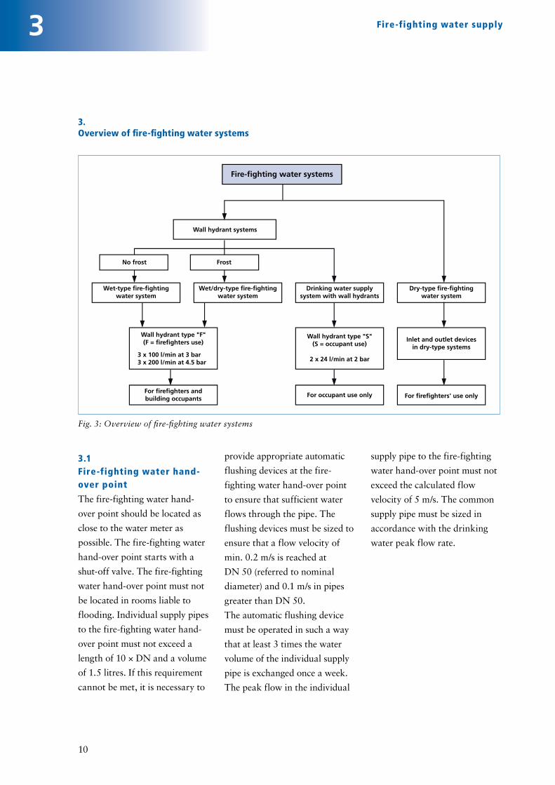
3. Overview of fire-fighting water systems
3
supply pipe to the fire-fighting
water hand-over point must not
exceed the calculated flow
velocity of 5 m/s. The common
supply pipe must be sized in
accordance with the drinking
water peak flow rate.
provide appropriate automatic
flushing devices at the fire-
fighting water hand-over point
to ensure that sufficient water
flows through the pipe. The
flushing devices must be sized to
ensure that a flow velocity of
min. 0.2 m/s is reached at
DN 50 (referred to nominal
diameter) and 0.1 m/s in pipes
greater than DN 50.
The automatic flushing device
must be operated in such a way
that at least 3 times the water
volume of the individual supply
pipe is exchanged once a week.
The peak flow in the individual
3.1 Fire-fighting water hand-over point
The fire-fighting water hand-
over point should be located as
close to the water meter as
possible. The fire-fighting water
hand-over point starts with a
shut-off valve. The fire-fighting
water hand-over point must not
be located in rooms liable to
flooding. Individual supply pipes
to the fire-fighting water hand-
over point must not exceed a
length of 10 × DN and a volume
of 1.5 litres. If this requirement
cannot be met, it is necessary to
Wall hydrant systems
Fire-fighting water systems
Wet-type fire-fightingwater system
Wet/dry-type fire-fightingwater system
Drinking water supplysystem with wall hydrants
Dry-type fire-fightingwater system
Wall hydrant type "S"(S = occupant use)
2 x 24 l/min at 2 bar
Inlet and outlet devicesin dry-type systems
Wall hydrant type "F"(F = firefighters use)
For occupant use only For firefighters' use onlyFor firefighters andbuilding occupants
3 x 100 l/min at 3 bar3 x 200 l/min at 4.5 bar
No frost Frost
Fig. 3: Overview of fire-fighting water systems
Fire-fighting water supply
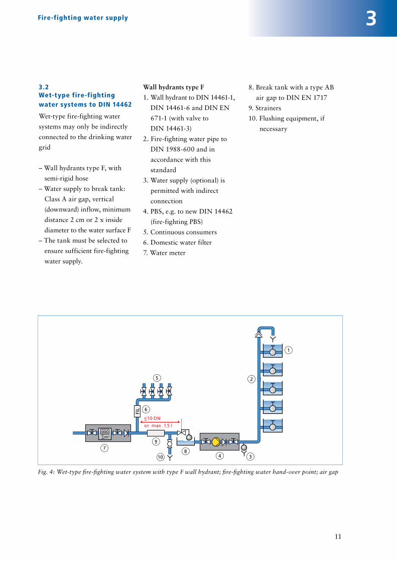
3.2Wet-type fire-fighting water systems to DIN 14462
Wet-type fire-fighting water
systems may only be indirectly
connected to the drinking water
grid
– Wall hydrants type F, with
semi-rigid hose
– Water supply to break tank:
Class A air gap, vertical
(downward) inflow, minimum
distance 2 cm or 2 x inside
diameter to the water surface F
– The tank must be selected to
ensure sufficient fire-fighting
water supply.
Wall hydrants type F
1. Wall hydrant to DIN 14461-1,
DIN 14461-6 and DIN EN
671-1 (with valve to
DIN 14461-3)
2. Fire-fighting water pipe to
DIN 1988-600 and in
accordance with this
standard
3. Water supply (optional) is
permitted with indirect
connection
4. PBS, e.g. to new DIN 14462
(fire-fighting PBS)
5. Continuous consumers
6. Domestic water filter
7. Water meter
8. Break tank with a type AB
air gap to DIN EN 1717
9. Strainers
10. Flushing equipment, if
necessary
11
000∑m3
5
4 3
1
2
6
79
8
FIL
10
Fig. 4: Wet-type fire-fighting water system with type F wall hydrant; fire-fighting water hand-over point; air gap
3Fire-fighting water supply

12
000∑m3
5
7
6
8 4
1
910
FIL
2
3
11
12
Wet/dry-type fire-fighting water system
Drinking water
3.3Wet/dry-type fire-fighting water systems to DIN 14462
Wet/dry-type fire-fighting water
systems may be directly or
indirectly connected to the
drinking water grid. In the case
of direct connection, external
water supply, e.g. by
firefighters, is not permitted via
– a fire-fighting water inlet
device
– wall hydrants with foaming
additives.
• Wall hydrants type F, with
semi-rigid hose
• Fire-fighting water with QFfw
and p supplied after a
maximum of 60 s
• Maximum pressure p = 8 bar
(holding pressure)
• If the pipe length between the
continuous consumers and
the centre of the solenoid
valve is ≤ 10 · DN or ≤ 1.5l of
pipe content, no flushing
equipment is necessary.
• If this distance is > 10 · DN,
then flushing equipment is
necessary: flush once a week,
3 times the pipe content at a
flow rate of
0.2 m/s up to DN 50
0.1 m/s above DN 50
Key:1. Pipe aerators and vents to DIN 14463-32. Wall hydrant to DIN 14461-1, DIN 14461-6 and DIN EN 671-1 (fire hose valve to DIN 14461-3 with limit switch)3. Fire-fighting water pipe to DIN 14463-1, DIN 1988- 600 and in accordance with this standard4. Fill and drain unit, e.g. to DIN 14463-1
5. Continuous consumers6. Domestic water filter7. Water meter8. E.g. membrane-type accumulator (optional)9. Pressure booster system (PBS)10. Break tank with a type AB air gap to DIN EN 171711. Strainer12. Flushing equipment, if necessary
Fig. 5: Directly connected wet/dry-type fire-fighting water system; fire-fighting water hand-over point: fill and drain unit
Water meter
000∑m3
Wet/dry-type fire-fighting water system
Drinking water5
6
FIL
1
2
3
47
11
<10·DN
or max. 1.5 l
12
Fig. 6: Indirectly connected wet/dry-type fire-fighting water system; fire-fighting water hand-over point: air gap
3 Fire-fighting water supply

000∑m3
FIL
65
74
1
1
1
1
3
2
Fig. 7: Drinking water installation with wall hydrant type S; fire-fighting water hand-over point: wall hydrant type S with safety combination
13
3.4Drinking water installation with wall hydrant type S (DIN 14462)
If the drinking water demand is
higher than the demand for
fire-fighting water, direct
connection is permitted under
the condition that piping ≤ 10 x
DN or max. 1.5 l pipe content
is observed.
Key:
1. Continuous consumers
2. Wall hydrant type S to
DIN 14461-1 (fire hose
connection valve to
DIN 14461-3 with safety
combination)
3. Drinking water pipe to
DIN 1988 and DIN EN 806
4. Drain
5. Domestic water filter
6. Water meter
7. PBS to DIN 1988-500
3Fire-fighting water supply

14
3.5 Planning and installation to DIN 14462
DIN 14462: Wall hydrant
systems
According to DIN 14462, wall
hydrants for occupant use must
be provided in conjunction with
wet/dry-type fire-fighting water
systems. The wall hydrants
installed for this purpose
should preferably be equipped
with semi-rigid hose types to
DIN 14461-1.
Wall hydrants with a flat hose
may only be used where
specially trained personnel are
continuously available.
Wall hydrants type S to
DIN 14461-1
Occupant use, not intended for
use by firefighters
Fire-fighting water flow rate:
2 x 24 l/min (= 2.88 m3/h) at a
flow pressure of 2 bar
Wall hydrants type F to
DIN 14461-1
Firefighter use (may also be
used by occupants to combat
incipient fires)
Fire-fighting water flow rate:
3 x 100 l/min (= 18 m³/h) at a
minimum flow pressure of 3 bar
Fire-fighting water flow rate:
3 x 200 l/min (= 36 m³/h) at a
minimum flow pressure of 4.5 bar The max. permissible flow
pressure or holding pressure of
8 bar must not be exceeded!
100
100
100
100
3
Fig. 8: Type S wall hydrant
Fig. 9: Type F wall hydrant
Fire-fighting water supply
15
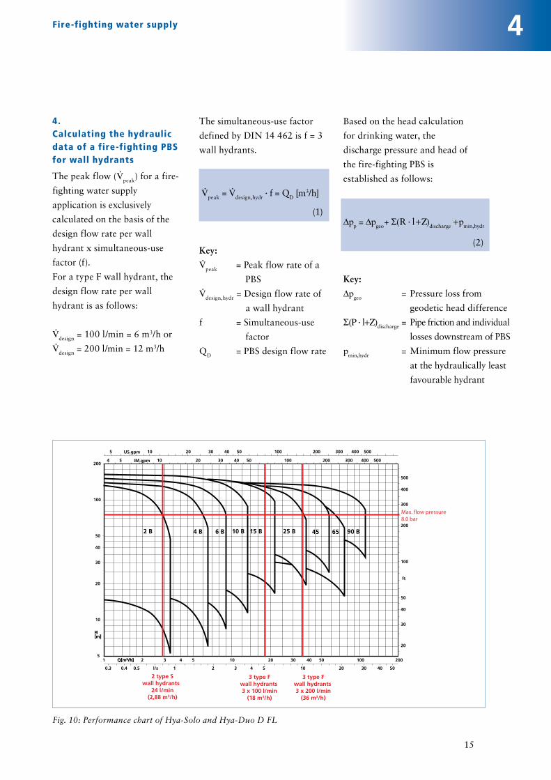
4. Calculating the hydraulic data of a fire-fighting PBS for wall hydrants
The peak flow (V· peak) for a fire-
fighting water supply
application is exclusively
calculated on the basis of the
design flow rate per wall
hydrant x simultaneous-use
factor (f).
For a type F wall hydrant, the
design flow rate per wall
hydrant is as follows:
V· design = 100 l/min = 6 m3/h or
V· design = 200 l/min = 12 m3/h
The simultaneous-use factor
defined by DIN 14 462 is f = 3
wall hydrants.
V· peak = V· design,hydr · f = QD [m3/h]
Key:
V· peak = Peak flow rate of a
PBS
V· design,hydr = Design flow rate of
a wall hydrant
f = Simultaneous-use
factor
QD = PBS design flow rate
Based on the head calculation
for drinking water, the
discharge pressure and head of
the fire-fighting PBS is
established as follows:
Δpp = Δpgeo + Σ(R · l+Z)discharge +pmin,hydr
(2)
(1)
Fig. 10: Performance chart of Hya-Solo and Hya-Duo D FL
H[m]
Q[m³/h]1 2 3 4 5 10 20 30 40 50 100 200Q[m³/h]
5 10 20 30 40 50 100 200 300 400 500US.gpm
4 5 10 20 30 40 50 100 200 300 400 500IM.gpm
5
10
20
30
40
50
100
200
H[m]
20
30
40
50
100
200
300
400
500
ft
0.3 0.4 0.5 1 2 3 4 5 10 20 30 40 50l/s
25 B2 B 4 B 6 B 10 B 15 B 90 B45 65
Max. flow pressure 8.0 bar
2 type Swall hydrants
24 l/min(2,88 m3/h)
3 type Fwall hydrants 3 x 100 l/min
(18 m3/h)
3 type Fwall hydrants 3 x 200 l/min
(36 m3/h)
Key:
Δpgeo = Pressure loss from
geodetic head difference
Σ(R · l+Z)discharge = Pipe friction and individual
losses downstream of PBS
pmin,hydr = Minimum flow pressure
at the hydraulically least
favourable hydrant
4Fire-fighting water supply

15 m
∑ HV= 0.6 bar
> 3.0 bar
0 bar
PBSVB
Fig. 13: Hya- Solo D FL
16
4.1 Calculation example 1
Office and administration building
– 5 floors, each with a height of 3.0 m
– Type F wall hydrants
100 l/min at 3 bar
– Remotest hydrant 40 m (15 mbar/m)
– Single-pump PBS
Δpp = Δpgeo + Σ(R · l+Z)discharge+pmin,hydr
= 1.5 bar + 0.6 bar + 3.0 bar
= 5.1 bar
V· peak = V· design,hydr · f
V· peak = 100 l/min x 3 = 300 l/min
= 18 m3/h^
Fig. 12: Characteristic curve of Hya-Solo D FL 1/1505
(3)
(4)
0 5 10 15 18 20 25
0 US.gpm
0 IM.gpm
0
5055
250
100
150
200
270
m
0
200
400
600
800
ft
/l0 2 4 6s
15/17 15 kW
15/15 15 kW
15/13 15 kW
15/11 11 kW
15/10 11 kW
15/9 11 kW
15/8 7,5 kW
15/7 7,5 kW
15/6 5,5 kW
15/5 5,5 kW
15/4 4 kW
15/3 3 kW
15/2 2,2 kW
15/1 1,1 kW
20 40 60 80 100
20 40 60 80Q min *)
m3/h
4
Fig. 11: System diagram
Fire-fighting water supply
17
Fig. 15: Hya-Duo D FL Compact
Fig.16: Characteristic curve of Hya-Duo D FL 2/4504
H [m]
Q [m3/h]
160
150
140
130
120
110
100
90
80
70
60
50
40
30
20
10
00 5 10 15 20 25 30 35 40 45 50 55 60
45/5
45/4-1
45/6
45/4
45/6-1
45/5-1
Max. flow pressure 8.0 bar
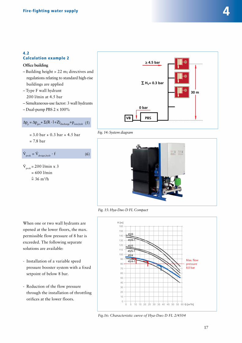
4.2Calculation example 2
Office building
– Building height > 22 m; directives and
regulations relating to standard high-rise
buildings are applied
– Type F wall hydrant
200 l/min at 4.5 bar
– Simultaneous-use factor: 3 wall hydrants
– Dual-pump PBS 2 x 100%
Δpp = Δpgeo + Σ(R · l+Z)discharge+pmin,hydr
= 3.0 bar + 0.3 bar + 4.5 bar
= 7.8 bar
V· peak = V· design,hydr · f
V· peak = 200 l/min x 3
= 600 l/min
= 36 m3/h
When one or two wall hydrants are
opened at the lower floors, the max.
permissible flow pressure of 8 bar is
exceeded. The following separate
solutions are available:
- Installation of a variable speed
pressure booster system with a fixed
setpoint of below 8 bar.
- Reduction of the flow pressure
through the installation of throttling
orifices at the lower floors.
^
30 m
∑ HV= 0.3 bar
> 4.5 bar
0 bar
PBSVB(5)
(6)
4
Fig. 14: System diagram
Fire-fighting water supply

Fig. 18: Hya-Duo DV FL Compact
Fig. 19: Characteristic curve of Hya-Duo D FL 2/4505
^
(7)
(8)
Fig. 17: System diagram
18
4
4.3Calculation example 3
Office building
– Building height > 22 m; directives and
regulations relating to standard high-
rise buildings are applied
– Type F wall hydrant
200 l/min at 4.5 bar
– Simultaneous-use factor: 3 wall hydrants
– Dual-pump PBS 2 x 100%
Δpp = Δpgeo + Σ(R · l+Z)discharge+pmin,hydr
= 4.0 bar + 0.5 bar + 4.5 bar
= 9.0 bar
V· peak = V· design,hydr · f
V· peak = 200 l/min x 3
= 600 l/min
= 36 m3/h
When wall hydrants are opened, the
max. permissible flow pressure of 8
bar is generally exceeded. To prevent
this, the following options are
available:
- Installation of a variable speed
pressure booster system with two
fixed setpoints, e.g. high pressure via
pressure control and low pressure via
limit switch
- Throttling orifices at the lower
floors.
^
30 m
∑ HV= 0.3 bar
> 4.5 bar
0 bar
PBSVB
H [m]
Q [m3/h]
160
150
140
130
120
110
100
90
80
70
60
50
40
30
20
10
00 5 10 15 20 25 30 35 40 45 50 55 60
45/5
45/4-1
45/6
45/4
45/6-1
45/5-1
Max. flow pressure 8.0 bar
Fire-fighting water supply
(9)
19
5
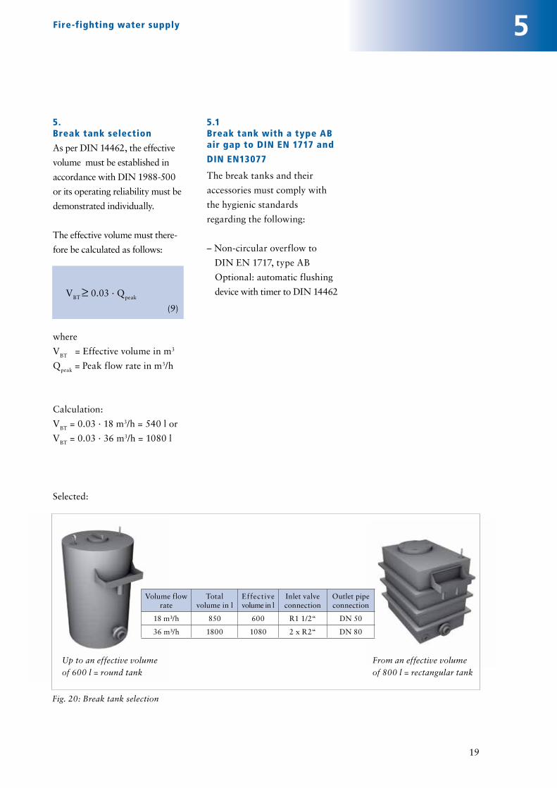
5. Break tank selection
As per DIN 14462, the effective
volume must be established in
accordance with DIN 1988-500
or its operating reliability must be
demonstrated individually.
The effective volume must there-
fore be calculated as follows:
VBT ≥ 0.03 · Qpeak
where
VBT = Effective volume in m3
Qpeak = Peak flow rate in m3/h
Calculation:
VBT = 0.03 · 18 m3/h = 540 l or
VBT = 0.03 · 36 m3/h = 1080 l
Selected:
Up to an effective volume
of 600 l = round tank
5.1Break tank with a type AB air gap to DIN EN 1717 and
DIN EN13077
The break tanks and their
accessories must comply with
the hygienic standards
regarding the following:
– Non-circular overflow to
DIN EN 1717, type AB
Optional: automatic flushing
device with timer to DIN 14462
Volume flow rate
Total volume in l
Effective volume in l
Inlet valve connection
Outlet pipe connection
18 m³/h 850 600 R1 1/2“ DN 50
36 m³/h 1800 1080 2 x R2“ DN 80
From an effective volume
of 800 l = rectangular tank
Fig. 20: Break tank selection
Fire-fighting water supply

20
6
6. Selection chart for auto-matic flushing device
In order to comply with the
requirements for drinking water
hygiene, an automatic flushing
device must be provided for a
branch pipe larger than 10x DN
or a 1.5 l pipe content.
Selection chart for solenoid
valves
At least 3 times the pipe content
must be flushed once a week!
20
10
18
0
40
50
60
70
80
30Q m3/h
0 1 2 3 4 5 6Pinl [bar]
1½" solenoid valve
½" solenoid valve
1" solenoid valve
Fig. 21: Hya-Duo D FL with
break tank
Nominal
diameter
Flow velocity
≥ DN 50 min. 0.2 m/s
< DN 50 min. 0.1 m/s
Fig. 22: Selection diagram for flushing device
Fire-fighting water supply

21
7. Continued use
7.1Excerpt from the Drinking Water Ordinance
§ 4 The Drinking Water
Ordinance requirements are
complied with if the generally
accepted technical rules and the
values as per §§ 5-7 are heeded.
§§ 5 -6 Microbiological and
chemical concentrations must
be kept as low as possible in
accordance with the accepted
technical rules. (§ 7 Indicator
parameters)
If the drinking water in the
network is stagnating it is not
possible to meet the permissible
microbiological and chemical
concentration requirements.
7.2Excerpt from DIN 1988-600 (translation)
Dealing with fire-fighting
systems and fire protection
systems in combination with
existing drinking water
installations in accordance with
DIN 1988-600.
If the Drinking Water
Ordinance requirements are not
met, the continued-use right for
a drinking water installation
used in combination with a fire-
fighting/fire protection system
will cease.
If existing systems which do not
comply with the regulations are
expanded, refurbished or
repaired these systems must not
only comply with the Drinking
Water Ordinance, but also meet
the fire protection requirements.
8.Log book
A log book must be kept which
documents the fire-fighting
water system.
The following should be
documented:
a) Property description:
property's name and address,
owner(s), operator(s), system
installation contractor,
authorities, i.e. approval
authority/fire protection
authority, water and electricity
providers.
b) Building requirements and
planning fundamentals:
- Design of fire-fighting water
pipes and their fire hose
connection equipment:
- Wet-type, wet-/dry-type, dry-
type fire-fighting water
systems; drinking water
installations with wall
hydrants.
- Fire-fighting water supply
c) Technical documentation:
plan of wall hydrants installed;
acceptance testing result;
maintenance and inspection/
test certificates; evidence of
measures taken for drinking
water protection.
9.Products offered by KSB
The following KSB systems can
be used for these applications:
Hya-Solo D FL
- Fully automatic single-pump
fire-fighting system
- Ready-to-connect package
system on a common
baseplate
Hya-Solo D FL Compact
- Fully automatic single-pump
break tank packaged booster
set for fire fighting, modular
design
Hya-Duo D FL
- Fully automatic dual-pump
fire-fighting system with
redundant function
- Ready-to-connect package
system on a common
baseplate
Hya-Duo D FL Compact
- Fully automatic dual-pump
break tank packaged booster
set for fire-fighting, with
redundant function, modular
design
If the fire-fighting water system
calculations reveal that the
max. permissible flow pressure
of 8 bar will be exceeded, the
above systems can be equipped
with a frequency inverter.
7Fire-fighting water supply

22
Sele
ctio
n of
KSB
bre
ak t
ank
pack
aged
boo
ster
set
s fo
r fi
re-f
ight
ing
DW
pre
ssur
e pi
peFl
amm
able
mat
eria
l?
Plea
se t
ick
whe
re a
pplic
able
Yes
No
Loca
tion
of
fire
-fig
htin
g sy
stem
:
Plea
se t
ick
whe
re a
pplic
able
abov
e fl
ood
leve
lbe
low
flo
od le
vel
Yes
No
Hig
h-ri
se b
uild
ing
Num
ber
of f
loor
s:Fl
oor
heig
ht:
Min
. flo
w p
ress
ure:
at t
he r
emot
est
hydr
ant
Num
ber
of h
ydra
nts:
Pipe
leng
th:
Hyd
rant
flo
w r
ate:
> 22
m f
rom
the
gro
und
floo
r to
the
hig
hest
occ
upie
d fl
oor
< 22
m f
rom
the
gro
und
floo
r to
the
hig
hest
occ
upie
d fl
oor
Num
ber
from
loca
tion
of
fire
-fig
htin
g sy
stem
m
Pipe
leng
th u
p to
the
rem
otes
t hyd
rant
Nom
inal
dia
met
er
m
bar
(
3.0b
ar
or
4.
5bar
)
sim
ulta
neou
s
Inle
t pr
essu
re:
bar
ml/min
(1
00 l/
min
or
200
l/m
in)
at
a
t
DN
DN80DN65DN50
Emer
genc
y dr
aina
ge
belo
w f
lood
le
vel:
lifti
ng u
nit
abov
e fl
ood
leve
l: se
wer
AnnexSelection of KSB break tank packaged booster set for fire-fighting
Fire-fighting water supply

How to order the KSB know-how series
At your request, we will be pleased to send you all KSB know-how volumes previouslypublished. Ordering is easy.
You may order the following know-how volumes:
• 0101.5 “Selecting Centrifugal Pumps“ DE, EN-UK, FR
• 0101.55 “Water Hammer“ DE, EN-UK
• 0508.023 “BOA-Systronic®“ DE, EN-UK
• 2300.02 “Planning Information for Drainage Installations“ DE, EN-UK
• 2300.024 “Pump Control / System Automation“ DE, EN-UK, FR
• 2300.025 “Planning Information for Pressure Booster Systems“ DE, EN-UK
• 0118.55 “Planning Information Amacan® Submersible Pumps in Discharge Tubes“ DE, EN-UK, EN-US, ES
• 2554.025 “KRT Planning Information“ DE, EN-UK, EN-US, ES
• 2300.023 “Planning Information for Fire-Fighting Systems“ DE, EN-UK
Just get in touch with us via our web site:
• http://www.ksb.com/ksb-en/contactfinder/
• Choose your country and/or post or ZIP code.
• Simply send an e-mail to the competent sales house or local company, stating the know-how volumes you require.
PO number Subject Available languages

KSB AktiengesellschaftJohann-Klein-Straße 967227 Frankenthal (Germany) www.ksb.com 23
00.0
23-E
N /
03.1
4 / ©
KSB
Akt
ien
ges
ells
chaf
t 20
13 ·S
ub
ject
to
tec
hn
ical
mo
dif
icat
ion
wit
ho
ut
pri
or
no
tice
The KSB-newsletter –
dont‘ miss out, sign up now
www.ksb.com/newsletter
Technology that makes its mark
Your contact: