planning guidelines and design standards for checked
TRANSCRIPT

TSA506
Planning Guidelines and Design
Standards for Checked Baggage
Inspection Systems
Version 2.0
January 30, 2009

TSA506
[THIS PAGE INTENTIONALLY LEFT BLANK]

TSA506
Planning Guidelines and Design
Standards for Checked Baggage
Inspection Systems Version 2.0
January 30, 2009

TSA506
[THIS PAGE INTENTIONALLY LEFT BLANK]

Planning Guidelines and Design Standards for Checked Baggage Inspection Systems Version 2.0 January 30, 2009 TSA506
NOTICE
This document is distributed under the sponsorship of the Transportation Security Administration of the U.S. Department of Homeland Security in the interest of information exchange. The U.S. Government assumes no liability for the contents or use.
This document does not create regulatory requirements. There are recommendations and guidelines contained in this document that might be considered highly beneficial in one airport environment while being virtually impossible to implement at another airport. The purpose of the document is to provide as extensive a list of options, ideas, and suggestions as possible for the airport architect, designer, planner and engineer to choose from when first considering security requirements in the early planning and design of new or renovated airport facilities.
This document has been formatted for double sided printing.
VERSION HISTORY
Version Date Modifications
0.1 December 29, 2006 Original submittal by BSIS Technical Team 0.2 June 21, 2007 Update based on TSA technical review 0.3 July 12, 2007 Update based on TSA program office review 1.0 October 10, 2007 Update based on SSI and final TSA review 2.0 October 31, 2008 Update based on recommended follow-on
studies as well as comments to the October 10, 2007 published version

Planning Guidelines and Design Standards for Checked Baggage Inspection Systems Version 2.0 January 30, 2009 TSA506
[THIS PAGE INTENTIONALLY LEFT BLANK]

Planning Guidelines and Design Standards for Checked Baggage Inspection Systems Version 2.0 January 30, 2009 i TSA506
CONTENTS
Chapter Page
1 INTRODUCTION ...................................................................................... 1-1 1.1 Background........................................................................................ 1-1 1.2 Previous Versions of Planning and Design Guidelines .............. 1-3 1.3 Purpose............................................................................................... 1-3 1.4 Scope ................................................................................................... 1-4 1.5 Organization ...................................................................................... 1-4 1.6 Referenced Documents and Models............................................... 1-6
1.6.1 Recommended Security Guidelines for Airport Planning, Design and Construction, Revised July 2006 .. 1-6
1.6.2 Integrated Deployment Model............................................ 1-6 1.6.3 Checked Baggage Inspection System (CBIS) Interface
Requirements Document ..................................................... 1-6 1.7 Next Steps .......................................................................................... 1-6
1.7.1 Design Issues ......................................................................... 1-7 1.7.2 Post-Implementation Issues................................................. 1-7 1.7.3 Funding Issues....................................................................... 1-7
1.8 Industry Comments.......................................................................... 1-7
2 GUIDELINES CONTEXT AND PRIMARY OBJECTIVES................... 2-1 2.1 Need for PGDS .................................................................................. 2-1 2.2 Emphasis and Objectives of Guidelines ........................................ 2-2
2.2.1 Lowest-Cost Solutions.......................................................... 2-2 2.2.2 Operational Performance Standards .................................. 2-3 2.2.3 Avoiding Common Pitfalls .................................................. 2-3 2.2.4 Appropriate Initial System Sizing ...................................... 2-3 2.2.5 Equipment Redundancy and Contingency Operations .. 2-3 2.2.6 Accommodating Growth ..................................................... 2-4 2.2.7 Flexibility................................................................................ 2-4 2.2.8 Stakeholder Involvement ..................................................... 2-4 2.2.9 Design Review and Approval Process............................... 2-5
3 PLANNING AND DESIGN PROCESS................................................... 3-1 3.1 Roles and Responsibilities ............................................................... 3-1
3.1.1 Project Stakeholders.............................................................. 3-1 3.1.2 Project Sponsor ...................................................................... 3-2 3.1.3 Integrated Local Design Team ............................................ 3-2 3.1.4 TSA.......................................................................................... 3-2 3.1.5 Government-Industry Working Group ............................. 3-3 3.1.6 Summary ................................................................................ 3-3

Planning Guidelines and Design Standards for Checked Baggage Inspection Systems Version 2.0 January 30, 2009 ii TSA506
CONTENTS (continued)
Chapter Page
3 PLANNING AND DESIGN PROCESS (continued) 3.2 Project Phases .................................................................................... 3-4
3.2.1 Pre-Design.............................................................................. 3-4 3.2.2 Schematic Design .................................................................. 3-6 3.2.3 Detailed Design ..................................................................... 3-7
3.2.3.1 30% Design Sub-Phase......................................... 3-7 3.2.3.2 70% Design Sub-Phase......................................... 3-8 3.2.3.3 100% Design Sub-Phase....................................... 3-9
3.2.4 Design-Build Projects ........................................................... 3-10 3.2.5 Construction Phase ............................................................... 3-11 3.2.6 Testing and Commissioning................................................ 3-12 3.2.7 Operations Training.............................................................. 3-12 3.2.8 Project Closeout Phase ......................................................... 3-13
3.3 Airport Funding Application Requirements ................................ 3-13 3.4 Summary ............................................................................................ 3-13
4 DESIGN STANDARDS ............................................................................. 4-1 4.1 General Design Requirements ........................................................ 4-1
4.1.1 Security ................................................................................... 4-1 4.1.2 Efficiency ................................................................................ 4-1 4.1.3 Passenger Level-Of-Service ................................................. 4-1 4.1.4 Cost-Effectiveness ................................................................. 4-2 4.1.5 Concept of Operation ........................................................... 4-2 4.1.6 Proper System Selection and Sizing ................................... 4-2
4.2 Specific Design Requirements......................................................... 4-2 4.2.1 BHS Capacity ......................................................................... 4-3 4.2.2 Screening Throughput Capacity ......................................... 4-3 4.2.3 Bag Time in System............................................................... 4-3 4.2.4 OSR Decision Time ............................................................... 4-3 4.2.5 BHS Tracking ID.................................................................... 4-3
4.2.5.1 Positive Bag Tracking .......................................... 4-3 4.2.5.1.1 Use of Real-Time Belt Speeds............. 4-3 4.2.5.1.2 Placement of Photoelectric Cells
(PECs) .................................................... 4-4 4.2.5.2 Error Bags at Checked Baggage Resolution
Area (CBRA).......................................................... 4-4 4.2.6 Bag Tag Identification........................................................... 4-4 4.2.7 Conveyor Control.................................................................. 4-4
4.2.7.1 Variable Frequency Drives.................................. 4-4 4.2.7.1.1 Dynamic Braking ................................. 4-4
4.2.7.2 Gradual Conveyor Speed Transitions ............... 4-4 4.2.8 Avoidance of Steep Conveyor Slopes ................................ 4-5

Planning Guidelines and Design Standards for Checked Baggage Inspection Systems Version 2.0 January 30, 2009 iii TSA506
CONTENTS (continued)
Chapter Page
4 DESIGN STANDARDS (continued) 4.2.9 Divert and Merge .................................................................. 4-5 4.2.10 Conveyable Items.................................................................. 4-5
4.2.10.1 Proper Handling of Oversize Bags .................... 4-5 4.2.10.2 Proper Handling of Out-of-Gauge Bags ........... 4-5
4.2.11 Fail Safe Operation................................................................ 4-6 4.2.12 Image Quality (IQ) Test Requirements .............................. 4-6 4.2.13 Bag Orientation/Positioning ............................................... 4-6 4.2.14 Bag Jam Rate .......................................................................... 4-6 4.2.15 BHS Displays at CBRA......................................................... 4-6 4.2.16 Alarmed Bag Images at CBRA ............................................ 4-6 4.2.17 Placement of Reinsertion Points ......................................... 4-6 4.2.18 Purge Line .............................................................................. 4-7 4.2.19 Recirculation Loops .............................................................. 4-7 4.2.20 Power Turns after EDS......................................................... 4-7 4.2.21 Non-Powered Rollers ........................................................... 4-7 4.2.22 Draft Curtains ........................................................................ 4-7 4.2.23 Accessibility of EDS Machines for Operation,
Maintenance and Replacement ........................................... 4-7 4.2.24 Location for Staging Equipment Prior to Installation...... 4-7 4.2.25 CBIS Reporting ...................................................................... 4-8 4.2.26 Jam Clearing Procedures and Safety .................................. 4-8 4.2.27 CBRA Ergonomic Design Considerations......................... 4-9
4.3. PGDS Effective Dates and Non-Conforming CBIS ...................... 4-10 4.3.1 Intent ....................................................................................... 4-10 4.3.2 PGDS Applicability............................................................... 4-10 4.3.3 Delayed Opening of CBIS .................................................... 4-10 4.3.4 Major Redesigns .................................................................... 4-10
5 SYSTEM TYPES AND SCREENING EQUIPMENT ............................. 5-1 5.1 Screening System Configurations................................................... 5-1
5.1.1 System Type 1: High-Volume In-Line CBIS..................... 5-2 5.1.2 System Type 2: Medium-Volume In-Line CBIS............... 5-7 5.1.3 System Type 3: Mini In-Line CBIS..................................... 5-11 5.1.4 System Type 4: Stand-Alone EDS ...................................... 5-17 5.1.5 System Type 5: Stand-Alone ETD Systems ...................... 5-21
5.1.5.1 Primary Screening ................................................ 5-21 5.1.5.2 Alarm Resolution.................................................. 5-22
5.2 EDS Certification Process................................................................. 5-24 5.2.1 Non-Detection Related Assessments ................................. 5-24 5.2.2 Detection-Related Assessments .......................................... 5-24
5.3 Status of Future Technologies ......................................................... 5-25
Planning Guidelines and Design Standards for Checked Baggage Inspection Systems Version 2.0 January 30, 2009 iv TSA506
CONTENTS (continued)
Chapter Page
6 BAGGAGE SCREENING DEMAND...................................................... 6-1 6.1 Categorization into Screening Zones ............................................. 6-1 6.2 Checked Baggage Flow Generation ............................................... 6-4
6.2.1 List of Airlines ....................................................................... 6-4 6.2.2 Determination of the ADPM per Screening Zone ............ 6-4 6.2.3 Flight Schedule ...................................................................... 6-5 6.2.4 Airline Load Factors ............................................................. 6-5 6.2.5 Origin/Destination and Connecting Passenger
Percentages............................................................................. 6-5 6.2.6 Earliness Distributions ......................................................... 6-6 6.2.7 Lateness Distributions .......................................................... 6-9 6.2.8 Checked Bags per Passenger ............................................... 6-10 6.2.9 Calibration of Flight Schedule-Driven Demand............... 6-12
6.3 Future Baggage Flow Projections ................................................... 6-12 6.3.1 Design Year for Equipment Requirements........................ 6-12 6.3.2 Accommodating Traffic Growth after the Design Year .. 6-13
7 BAGGAGE SCREENING EQUIPMENT REQUIREMENTS ............... 7-1 7.1 Requirements During the Pre-Design Phase ................................ 7-1
7.1.1 EDS Equipment Requirements............................................ 7-1 7.1.2 EDS Equipment Redundancy.............................................. 7-3 7.1.3 OSR Station Requirements................................................... 7-4 7.1.4 ETD Screening Station Requirements ................................ 7-7
7.2 Equipment Requirements During the Schematic and Detailed Design Phases .................................................................................... 7-8
7.3 Recommended Simulation Standards............................................ 7-9 7.3.1 General Standards................................................................. 7-10 7.3.2 Statistical Distributions ........................................................ 7-10
8 CONTINGENCIES..................................................................................... 8-1 8.1 Contingency Planning Process........................................................ 8-1 8.2 General Considerations.................................................................... 8-1 8.3 Design Recommendations to Facilitate Contingency Planning . 8-2
8.3.1 Equipment Redundancy ...................................................... 8-2 8.3.2 Programming Logic .............................................................. 8-3 8.3.3 Out-of-Gauge Diverter—Bypass to ETD ........................... 8-3 8.3.4 Provision for Manual Conveyance of Baggage................. 8-3 8.3.5 Emergency and Standby Power.......................................... 8-3
8.4 Alternative TSA Screening Measures ............................................ 8-4
Planning Guidelines and Design Standards for Checked Baggage Inspection Systems Version 2.0 January 30, 2009 v TSA506
CONTENTS (continued)
Chapter Page
8 CONTINGENCIES (continued) 8.5 Failure Types and Mitigation Measures ........................................ 8-4
8.5.1 Short-Duration Failures........................................................ 8-4 8.5.2 Medium-Duration Failures.................................................. 8-5 8.5.3 Long-Duration Failures ........................................................ 8-5
8.6 Evaluation of Contingency Alternatives ....................................... 8-6 8.6.1 General Principles for Evaluation....................................... 8-6 8.6.2 Mini In-Line System Example ............................................. 8-6
9 DEVELOPMENT AND EVALUATION OF ALTERNATIVES........... 9-1 9.1 Developing Alternatives .................................................................. 9-1
9.1.1 Airline Grouping Assignments (Screening Zones) .......... 9-1 9.1.2 Tradeoffs between Screening Systems............................... 9-2 9.1.3 Tradeoffs between Upfront Capacity and Incremental
Capacity .................................................................................. 9-4 9.2 Estimating Life-Cycle Costs............................................................. 9-4
9.2.1 Analysis Assumptions.......................................................... 9-5 9.2.1.1 Life-Cycle Cost Analysis Period......................... 9-5 9.2.1.2 Equipment Life-Cycle .......................................... 9-5 9.2.1.3 Construction Period ............................................. 9-5 9.2.1.4 Constant Dollar Cost............................................ 9-5
9.2.2 Life-Cycle Costs to Consider ............................................... 9-6 9.2.3 Estimating Capital Costs...................................................... 9-6
9.2.3.1 Screening Equipment Purchase Price ................ 9-6 9.2.3.2 Screening Equipment Direct Installation Costs 9-8 9.2.3.3 Screening Equipment Refurbishment and
Upgrade Costs....................................................... 9-9 9.2.3.4 Screening Equipment Replacement Costs ........ 9-11 9.2.3.5 Cost of EDS Removal ........................................... 9-11 9.2.3.6 EDS Residual Value and Disposal Cost ............ 9-11 9.2.3.7 Costs of Required Building and BHS
Modifications ........................................................ 9-12 9.2.4 Estimating O&M Costs......................................................... 9-13
9.2.4.1 Screening Equipment Maintenance Costs ........ 9-13 9.2.4.2 Screening Equipment Operating Costs ............. 9-14 9.2.4.3 Incremental BHS Maintenance Costs ................ 9-15 9.2.4.4 Incremental BHS Operating Costs ..................... 9-16
9.2.5 Estimating Staffing Costs ..................................................... 9-16 9.2.5.1 TSA Screener and Supervisor Costs .................. 9-16 9.2.5.2 Incremental Costs for Baggage Porters and
Other Airport/Airline Staff ................................ 9-17 9.3 Selecting the Preferred Alternative ................................................ 9-17

Planning Guidelines and Design Standards for Checked Baggage Inspection Systems Version 2.0 January 30, 2009 vi TSA506
APPENDICES
A Introduction to In-Line Checked Baggage Inspection Systems
B Generic Examples of Checked Baggage Inspection Systems
C Basis of Design Report Example Case Study—Oakland International Airport
D Checked Baggage Inspection System Requirements
D1 – Design Performance Requirements
D2 – Commissioning and Evaluation Requirements
E Example Contingency Plan
F Report Submittal Templates
G Mini In-Line CBIS Standardization

Planning Guidelines and Design Standards for Checked Baggage Inspection Systems Version 2.0 January 30, 2009 vii TSA506
TABLES
Page
5-1 Potential High-Volume EDS Machines—Equipment Assumptions.......... 5-5
5-2 Potential Medium-Volume EDS Machines—Equipment Assumptions.... 5-9
5-3 Potential Mini In-Line EDS Machines—Equipment Assumptions ............ 5-15
5-4 Potential Stand-Alone EDS Machines—Equipment Assumptions ............ 5-19
5-5 Potential ETD Machines—Equipment Assumptions ................................... 5-23
5-6 Expected Availability of Checked Baggage Screening Equipment............ 5-26
6-1 Example Earliness Distribution....................................................................... 6-8
6-2 Summary of Input Data Needs and Potential Data Sources ....................... 6-11
9-1 Purchase Price of Checked Baggage Screening Equipment ........................ 9-7
9-2 Components of Direct Installation Costs ....................................................... 9-8
9-3 Direct Installation Cost of Screening Equipment.......................................... 9-9
9-4 EDS Refurbishment and Upgrade Options ................................................... 9-10
9-5 Infrastructure Modification Costs for EDS Replacement ............................ 9-11
9-6 Average Cost of Facility Modifications and Infrastructure......................... 9-13
9-7 Screening Equipment Maintenance Cost Assumptions............................... 9-14
9-8 Screening Equipment Power Consumption .................................................. 9-15
9-9 Estimated Annual Incremental BHS Maintenance Costs ............................ 9-16

Planning Guidelines and Design Standards for Checked Baggage Inspection Systems Version 2.0 January 30, 2009 viii TSA506
FIGURES
Page
2-1 Summary of the Design Process Phases......................................................... 2-7
3-1 Summary of Responsibilities During the Design Process ........................... 3-3
3-2 Summary of CBIS Design Review Flow......................................................... 3-14
3-3 Summary of Planning and Design Process.................................................... 3-15
5-1 Schematic Visualization of a High-Volume In-Line System ....................... 5-2
5-2 Schematic Visualization of a Medium-Volume In-Line System................. 5-7
5-3 Schematic Visualization of a Mini In-Line System ....................................... 5-11
5-4 Schematic Visualization of A Mini In-Line System with Light Integration (S-Configuration) .......................................................................... 5-13
5-5 Schematic Visualization of a Stand-Alone EDS ............................................ 5-17
5-6 Schematic Visualization of a Stand-Alone ETD System .............................. 5-21
6-1 Zone Hierarchy Representation ...................................................................... 6-2
6-2 Assumed Screening Zones at Albuquerque International Sunport ........... 6-3
6-3 Example Earliness Distributions Before and After 9 a.m. ........................... 6-7
6-4 Example Earliness Distributions for Domestic and International Carriers................................................................................................................ 6-9
6-5 Example Lateness Distribution........................................................................ 6-10
7-1 10-Minute ADPM Checked Baggage Flow.................................................... 7-3
7-2 Approach TO Modeling System Requirements ............................................ 7-9
9-1 System Type Comparison ................................................................................ 9-2

Planning Guidelines and Design Standards for Checked Baggage Inspection Systems Version 2.0 January 30, 2009 ix TSA506
ACRONYMS AND ABBREVIATIONS
ACWP Actual Cost of Work Performed ADPM Average Day of the Peak Month ASAC Aviation Security Advisory Committee ASDG-WG Airport Security Design Guidelines Working Group ATO Airline Ticket Office ATR Automatic Tag Reader ATSA Aviation and Transportation Security Act BAC Budget at Completion BCWP Budgeted Cost of Work Performed BDR Basis of Design Report BHS Baggage Handling System BHSC Baggage Handing System Contractor BHSO Baggage Handling System Oversize BIR Baggage Inspection Room BMA Baggage Measurement Array BOE Basis of Estimate BPH Bags Per Hour BRL Baggage Reinsertion Line BSIS Baggage Screening Investment Study BVS Baggage Viewing Station CBIS Checked Baggage Inspection System CBRA Checked Baggage Resolution Area CCI Construction Cost Index CPI Cost Performance Index CRT Certification Readiness Test CSI Construction Standards Institute CT Computerized Tomography CTO Chief Technology Officer CWE Current Working Estimate CY Calendar Year DBU Date of Beneficial Use DHS Department of Homeland Security DPR Design Performance Requirements DT&E Developmental Test and Evaluation EAC Estimate at Completion EBSP Electronic Baggage Screening Program EDS Explosives Detection System EDSO Explosives Detection System Out-of-Gauge ETD Explosives Trace Detection EVM Earned Value Management FAA Federal Aviation Administration FFY Federal Fiscal Year FIS Federal Inspection Services

Planning Guidelines and Design Standards for Checked Baggage Inspection Systems Version 2.0 January 30, 2009 x TSA506
ACRONYMS AND ABBREVIATIONS (continued)
FSD Federal Security Director FTE Full-Time Equivalent GAO Government Accountability Office HVAC Heating, Ventilation, and Air Conditioning IATA International Air Transport Association ILDT Integrated Local Design Team ISAT Integrated Site Acceptance Test IT Information Technology LCCA Life-Cycle Cost Analysis LOI Letter of Intent MES Manual Encode Station OOG Out-Of-Gauge O&M Operating and Maintenance OMB Office of Management and Budget OSR On-Screen Resolution OTA Other Transaction Agreement PGDS Planning Guidelines and Design Standards dated October 10, 2007 PEC Photoelectric Cell PFC Passenger Facility Charge Funding PLC Programmable Logic Controller PMO Program Management Office PNR Passenger Name Record PSP Passenger Screening Program RFID Radio Frequency Identification ROM Rough Order-of-Magnitude SAT Site Acceptance Test SOP Standard Operating Procedures SQT System Qualification Testing SSI Sensitive Security Information SSTP Site Specific Test Plan SV Schedule Variance TAF Terminal Area Forecast TCU Threat Containment Unit TEC Total Estimated Cost TSA Transportation Security Administration TSL Transportation Security Laboratory VAC Variance at Completion VFD Variable Frequency Drive WBS Work Breakdown Structure

Planning Guidelines and Design Standards for Checked Baggage Inspection Systems Version 2.0 January 30, 2009 xi TSA506
DEFINITIONS
CHECKED BAGGAGE INSPECTION SYSTEM (CBIS) – The entire system from Ticket Counter and Curbside lines, through the EDS screening area to the Clear and Sortation lines that lead to the bag make-up area.
CBIS CONVEYOR LINE DEFINITIONS
CBRA LINE – The conveyors that transport baggage from the OSR line to the CBRA removal points.
EDS LINES – The conveyors that transport baggage from diversion off of the Main Line through the EDS machine to diversion onto either the Clear Line or the OSR Line. Also referred to as: spurs, shunts, or subsystems.
INPUT LINES – Any conveyor line that is used for the induction of baggage.
MAIN LINE
PRE-EDS – Conveyor line where input lines are merged to create a main delivery conveyor line that delivers baggage for diversion to individual EDS lines.
POST-EDS - Conveyor line where all EDS Clear lines, which includes Level 1, Level 2, and Level 3 cleared baggage, are merged for transport to the make-up area.
OSR LINES – Lines after the EDS exit tunnel transporting baggage that has not yet received a “Clear” security screening decision. Each individual EDS machine is likely to be connected to individual OSR lines that merge on to a main OSR line that transports baggage to the Level 2 clear/alarm diversion point. On-Screen Resolution is performed on baggage that is traveling on these lines.
PURGE LINE – Conveyor line that connects the Alarmed line beyond the Level 2 decision point with the Main line feeding the group of EDS machines that transports bags off of an EDS line after an EDS machine has faulted. Positive tracking of bags must be maintained. This line could also be utilized when other forms of screening technology are implemented. This is not a recirculation line for lost in track bags.
CLEAR BAG – Any bag that has received a “Clear” security screening decision at Level 1, 2 or 3 security screening.
GROUP OF EDS MACHINES – Two or more EDS machines that are fed by a common Main line.

Planning Guidelines and Design Standards for Checked Baggage Inspection Systems Version 2.0 January 30, 2009 xii TSA506
LOST IN TRACK – A situation when the BHS loses positive tracking of a bag after the bag has (1) been acquired by the BHS and (2) assigned a BHS tracking ID to be positively tracked.
MODELING
HIGH LEVEL FLOW BASED – A deterministic model (typically using excel spreadsheets or other deterministic models) used to estimate design baggage demand for a CBIS in order to determine equipment and staffing requirements based on baggage flows. Fluid approximations of baggage demand (with or without statistical surging) are used to generate bag flows from flight schedules and passenger characteristics and estimating EDS, ETD equipment requirements as well as staffing requirements is done by dividing bag flows with equipment and staff throughput or screening capacity.
SIMULATION – A software package that enables a stochastic analysis of the CBIS. Simulation models can be visual (with 2-dimensional or 3-dimensional graphics) or non-visual (which generate statistical outputs only). Generally, simulation models for CBIS evaluation will be based on a discrete-event simulation software package. Simulation is used to assess the performance of the system (such as time in system, equipment utilization rates, equipment throughput rates, etc.) based on certain modeling assumptions. Analysis of outputs from the simulation model can provide a statistical validation of performance standards as well as equipment and staffing requirements. Visual outputs can also assist with stakeholder buy-in of the design.
NON-CLEAR BAG – Any bag pre- or post-EDS that has not received a “Clear” security screening decision at Level 1, 2, or 3 screening. (i.e., Alarmed, pending decision, unknown, lost-in-track, etc.).
TRACKING ZONE – Point at which the BHS acquires positive tracking of a bag prior to the EDS (normally at a BMA or ATR) to diversion to a Clear line or to removal for inspection in the CBRA.
UPSTREAM OF EDS – From positive tracking acquisition (normally at a BMA or ATR) to the last conveyor prior to entering the EDS machine.
DOWNSTREAM OF EDS – From the EDS entrance tunnel to diversion to a Clear line or removal for inspection in the CBRA.

Planning Guidelines and Design Standards for Checked Baggage Inspection Systems Version 2.0 January 30, 2009 xiii TSA506
ACKNOWLEDGEMENTS
The following is a list of members of the Baggage Screening Investment Study Technical Team, who contributed their time and insight into developing the original version of the BSIS Planning Guidelines and Design Standards (version 1.0 published in October 10, 2007).
Airport Authorities
Name Affiliation Jim Crites Dallas/Fort Worth International Airport Board Kevin Dillon City of Manchester, Aviation Department Jeff Fitch Aviation Division, Port of Seattle Dan Molloy Department of Aviation, City of Atlanta Airlines
Name Affiliation John Conlon Southwest Airlines Fred Clements Northwest Airlines Rick Garde JetBlue Airways Mike Golden Southwest Airlines Steve Mayberry Northwest Airlines Nick Meador American Airlines John McDonald United Airlines Terry Spradlin Delta Air Lines Federal Government Agencies and Contractors
Name Affiliation Amy Becke TSA Office of Security Technologies Mark Bernatowicz TSA Office of Security Technologies Robert Gentry TSA Office of Security Technologies Keith Goll TSA Office of Security Technologies Khalid Haider TSA Office of Security Technologies Dave Harder TSA Office of Security Technologies Stephanie Howlett TSA Office of Security Technologies Andy Lee TSA Office of Security Technologies Michael Salmen TSA Security Operations Robert Sheftel TSA Office of Security Technologies David Smith Battelle

Planning Guidelines and Design Standards for Checked Baggage Inspection Systems Version 2.0 January 30, 2009 xiv TSA506
Baggage Handling System Designers
Name Affiliation Gary Cline Siemens Gaylloyd Dadyala Venderlande Matthias Frenz LogPlan Archie Lind URS Jim Lusche Swanson Rink Mike Moser Raytheon Dan Stricklin G&T Larry Studdiford Cage Sal Terracianno Cage Vic Thompson Vic Thompson Company Security Equipment Manufacturers
Name Affiliation Kevin Coffey L-3 Communications Steven Hills General Electric Michael Lanzaro L-3 Communications Steve Pelham Reveal Cameron Ritchie General Electric David Schafer Analogic Elan Scheinman Reveal Brandon Sorrell Reveal Frank Vorwald Analogic David Webber General Electric
The Technical Team was supported by a project team led by Jacobs Consultancy Inc. and the Northrop Grumman Corporation.

Planning Guidelines and Design Standards for Checked Baggage Inspection Systems Version 2.0 January 30, 2009 xv TSA506
In addition, to prepare the document for distribution to the industry, the following individuals participated in a series of technical review workshops and contributed valuable insights to the refinement of version 1.0 as well as version 2.0 of the PGDS: Name Affiliation Jeff Callaghan Vic Thompson Company Jonathan Hill Vic Thompson Company Michael Benedetti TSA Office of Security Technologies Amy Becke TSA Office of Security Technologies Khalid Haider TSA Office of Security Technologies Steve McQueen TSA Office of Security Technologies Steve Mcvey TSA Office of Security Technologies Nick Meador TSA Office of Security Operations Scot Thaxton TSA Office of Security Operations Brian Nadreau Jacobs Consultancy Cheech Ong Jacobs Consultancy Amir Neeman Jacobs Consultancy Joseph Rojakovick Jacobs Consultancy John Reed TSA Office of Security Technologies David Smith Battelle Larry Studdiford Carter Burgess Sam Swearingen Carter Burgess Robert Ratcliffe Carter Burgess Richard Spies Carter Burgess James Lusche Swanson Rink Vic Thompson Vic Thompson Company

Planning Guidelines and Design Standards for Checked Baggage Inspection Systems Version 2.0 January 30, 2009 xvi TSA506
[THIS PAGE INTENTIONALLY LEFT BLANK]

Planning Guidelines and Design Standards for Checked Baggage Inspection Systems Version 2.0 January 30, 2009 1-1 TSA506
Chapter 1
INTRODUCTION
These planning guidelines and design standards for airport checked baggage inspection systems version 1.0 (PGDS) were prepared as part of the Baggage Screening Investment Study (BSIS) undertaken by the U.S. Transportation Security Administration (TSA) in consultation with the aviation industry during 2006 (referred to herein as the PGDS). The design principles and methods presented in the PGDS incorporate insights and experience of industry stakeholders, including TSA, airport and airline representatives, planners, architects, baggage handling system designers, and equipment manufacturers. The PGDS are intended to assist planners and designers in developing cost-effective solutions and to convey TSA requirements for checked baggage inspection systems (CBISs).
In particular, the PGDS provide specific guidance on ways to design baggage screening systems that (1) are less costly from both a capital and life-cycle perspective, and (2) have higher performance than the first generation of installed baggage screening systems. Lessons learned from previous installations are emphasized, as are the benefits and specifications of emerging new screening technologies. The PGDS also establish performance standards for CBIS (in particular appendix D1 and appendix D2), which all future CBIS must meet.
The first version of PGDS (version 1.0) was published on October 10, 2007 by TSA. During 2007 and 2008 many valuable industry comments were received from airports, airlines, designers and planners as well as from TSA. In addition several follow-on studies were conducted to carry-out as best as possible some of the next steps articulated in the PGDS (section 1.7). During the summer of 2008 TSA conducted a thorough comment review process in which comments as well as follow-on PGDS studies were incorporated as appropriate. The result of this review process is this second version of the PGDS (version 2.0).
1.1 BACKGROUND
The BSIS is a direct response to the requirements included in the Intelligence Reform and Terrorism Prevention Act of 2004 (Section 4019d), and is intended to respond to directives in the 2005 Department of Homeland Security (DHS) Appropriations Act Conference Report and recommendations contained in the March 15, 2005, Government Accountability Office (GAO) report. The Electronic Baggage Screening Program (EBSP) framework was developed as the basis for the BSIS. As described in the EBSP Strategic Planning Framework submitted to Congress in February 2006, the primary goals of the EBSP Strategic Plan are to:
1. Increase security through deploying explosives detection system (EDS) equipment to as many airports as practicable and implementing more labor-

Planning Guidelines and Design Standards for Checked Baggage Inspection Systems Version 2.0 January 30, 2009 1-2 TSA506
intensive explosives trace detection (ETD) screening protocols at those locations where ETD will continue to be used for primary screening.
2. Minimize EBSP life-cycle costs by deploying the best possible screening solutions at each airport, appropriately balancing capital investment and operating cost tradeoffs.
3. Minimize impacts to TSA and airport/airline operations through well-designed and well-placed EDS solutions.
4. Provide a flexible security infrastructure “platform” for accommodating growing airline traffic and other industry changes over the next 20 years and for addressing potential new threats.
To achieve these goals and fully implement the design philosophies embraced in the BSIS and the EBSP Strategic Planning Framework, the PGDS were developed as an industry reference for airport operators, airlines, planners, and designers who will be instrumental in implementing improved checked baggage screening systems. The focus of the PGDS is on in-line systems.
For the purpose of expediting the nationwide installation of checked baggage screening systems in an equitable, sustainable, and cost-effective manner, as required by legislation, the PGDS:
Establish common design principles and metrics that all screening system designs shall meet.
Consolidate the collective industry experience and insights on the best practices for planning, designing, and implementing baggage screening systems.
Disseminate the latest information on screening technologies, in-line screening concepts, and screening protocols.
Standardize the methodology for planning, designing, and evaluating various system design alternatives.
Since the large-scale deployment of EDS screening systems in 2002 and 2003, the aviation industry has had the opportunity to learn from implementation and operation of the initial in-line EDS installations. TSA checked baggage screening procedures have evolved and improved screening technologies have been developed. On the basis of the experience from earlier EDS installations, newly planned CBISs have also begun to incorporate features that enhance the durability of the baggage handling system (BHS) and maximize the performance of EDS equipment and the overall screening system.

Planning Guidelines and Design Standards for Checked Baggage Inspection Systems Version 2.0 January 30, 2009 1-3 TSA506
However, outstanding issues do exist that are addressed in this document:
Implementation of best practices during development of a screening system remains uneven, and the knowledge gained often stays (and differs) within a select group of airports, airlines, and CBIS designers.
The focus of in-line EDS concept development remains largely fixed on the substantial upfront capital investment and not on the sustainability of the system for all stakeholders (e.g., recurring costs to airlines and TSA).
Most in-line EDS concepts continue to focus on capital-intensive, centralized system designs and assume that each screening zone should have the same basic type of in-line system. The development of new EDS machines that differ in size and throughput (e.g., CT-80 and other technologies that could be certified in the near future) as well as add-on technologies (e.g., Baggage Viewing Station or BVS) have presented new options for in-line EDS screening systems. Innovative concepts, such as mini in-line EDS screening systems, have also been developed. A wide range of current in-line EDS screening systems have different tradeoffs among upfront capital costs, staffing efficiency, and spatial requirements. It is increasingly recognized that a “one size fits all” solution for every airport and terminal does not exist.
1.2 PREVIOUS VERSIONS OF PLANNING AND DESIGN GUIDELINES
The Aviation and Transportation Security Act (ATSA) required 100% electronic screening of checked baggage by December 31, 2002 (subsequently, this deadline was extended to December 31, 2003). As a result, a first set of planning and design guidelines for the installation of stand-alone EDS and ETD equipment was published in 2002. These guidelines did not, however, provide guidance on the development of in-line EDS.
To provide information on the lessons learned through the installation of CBISs at several airports since 2002, the Aviation Security Advisory Committee (ASAC) commissioned a working group to develop near-term checked baggage screening system planning and design guidelines, herein referred to as the Recommended Security Guidelines for Airport Planning, Design and Construction (the ASDG-WG Guidelines). These guidelines were published in June 2006 and contain information on best practices for CBIS design; however, they provide guidance only on technology certified as of the published date.
1.3 PURPOSE
While the ASDG-WG Guidelines primarily focus on currently certified technology, the PGDS follow the goals of the EBSP Strategic Planning Framework to expedite the cost-effective deployment of CBISs. To achieve these goals, the deployment of next-generation technology that has recently been certified, or is expected to be certified within the next 2 to 3 years, must be accelerated. Accordingly, the PGDS emphasize
Planning Guidelines and Design Standards for Checked Baggage Inspection Systems Version 2.0 January 30, 2009 1-4 TSA506
new technology and associated performance assumptions, screening protocols, and concepts of operation. In addition, the PGDS provide guidance regarding the economic analysis needed to support the selection of the most cost-effective system. The PGDS also provide a new planning and design process, which is focused around life cycle cost estimates and a participatory approach involving all relevant stakeholders at an early stage.
1.4 SCOPE
The PGDS are focused on the planning and design of CBIS which would generally comprise the following four screening processes:
Level 1—Primary screening using Explosive Detection Systems (EDS).
Level 2—Resolution of alarmed bags from Level 1 using on-screen resolution (OSR) techniques. Monitoring stations can be located at the EDS machine for local resolution or at remote locations with multiplexing capabilities.
Level 3—Resolution of alarmed bags from Level 2 using Explosive Trace Detection (ETD) machines in the checked baggage resolution area (CBRA).
Level 4—Ordinance disposal (e.g., loaded into a Threat Containment Unit).
The Guidelines also deal with some aspects of the installation, testing and commissioning of CBIS; however, issues related to the operation and maintenance of CBISs are not within the scope of the Guidelines. In addition, sources of funding and eligibility for use of specific financing mechanisms will be addressed in a separate document.
1.5 ORGANIZATION
The subsequent chapters of these PGDS are as follows:
Chapter 2, Guidelines Context and Primary Objectives—Overview of the context for developing the PGDS, as well as primary objectives.
Chapter 3, Planning and Design Process—Design package content, descriptions of the various phases of the design process and Guidelines applicability throughout the design process.
Chapter 4, Design Standards—Design requirements to ensure conformance with TSA security and operational performance standards.
Chapter 5, System Types and Screening Equipment—Detailed descriptions of screening equipment and screening system concepts.
Chapter 6, Baggage Screening Demand—Methodology and elements of demand forecasting.

Planning Guidelines and Design Standards for Checked Baggage Inspection Systems Version 2.0 January 30, 2009 1-5 TSA506
Chapter 7, Baggage Screening Equipment Requirements—Methodology for initially sizing screening systems.
Chapter 8, Contingencies—Summary of the process of developing a contingency plan, principles of contingency design, and evaluation of contingency alternatives.
Chapter 9, Development and Evaluation of Alternatives—Development of alternatives, including matching facility type to security equipment and baggage screening system design, assessing costs, establishing the economic value of alternatives, and determining the most cost-effective alternatives.
This document also contains the following appendices:
Appendix A—Introduction to In-Line Baggage Inspection Systems, which provides an overview of how screening of checked baggage is performed in a typical in-line CBIS.
Appendix B—Generic Examples of Checked Baggage Inspection Systems, which provides generic examples of baggage screening systems, operational assumptions, and best practices.
Appendix C—Pre-Design Phase Case Study for Oakland International Airport, which demonstrates how the PGDS should be followed to develop and select viable CBIS alternatives during the Pre-Design phase
Appendix D—Checked Baggage Inspection System Requirements, which consists of two parts:
D1 – Design Performance Requirements, which provides requirements that all CBIS designs must meet.
D2 – Commissioning and Evaluation Requirements, which provides guidelines for developing a Site Specific Test Plan (SSTP) used to test and commission the CBIS after installation.
Appendix E—Example Contingency Plan for Oakland International Airport, which demonstrates how a contingency plan related to CBIS operation should be developed.
Appendix F - Report Submittal Templates, which provides report submittal template for CBIS during the Pre-design and the Schematic Design Phase.
Appendix G – Mini In-Line CBIS Standardization, which provides further detail in regards to the planning and design of standardized mini in-line CBIS.
Planning Guidelines and Design Standards for Checked Baggage Inspection Systems Version 2.0 January 30, 2009 1-6 TSA506
1.6 REFERENCED DOCUMENTS AND MODELS
The PGDS were developed with reference to several documents and models previously developed by TSA and its contractors, as discussed below:
1.6.1 Recommended Security Guidelines for Airport Planning, Design and Construction, Revised July 2006
This revised document was issued by TSA in July 2006 and presents recommendations for incorporating sound security considerations into the planning, design, construction, and modification of security-related airport facilities and airport terminal buildings. It consolidates information developed through the participation of TSA and other government and aviation industry professionals. The Recommended Security Guidelines document is intended to help users ensure that security considerations and requirements are a component of the planning and design of airport infrastructure, facilities and operational elements. Intended users include aviation user-agencies (airport operators, aircraft operators and airport tenants), airport planners and consultants, designers, architects, and engineers engaged in renovation and new airport facility planning, design or construction projects.
1.6.2 Integrated Deployment Model
As part of the BSIS, TSA also developed the Integrated Deployment Model, which is an economic model based on a life-cycle cost approach to screening system selection. The model is used to conduct a top-down evaluation of various schematic concepts of EDS screening systems, based on the methodologies outlined in this document, at airports designated as Threat Category X, I, II, and III. These schematic concepts take into account high-level spatial constraints at airport terminals and are optimally sized according to the estimated checked baggage demand. The concepts were then evaluated on the basis of the life-cycle costs of developing, maintaining, and replacing the EDS screening systems. Though schematic in nature, these concepts may serve as a useful starting point for any airport or airline that plans to implement a checked baggage screening system and would be made available upon request.
The Integrated Deployment Model is a working model that will be continuously updated as new technologies are developed and performance characteristics are updated.
1.6.3 Checked Baggage Inspection System (CBIS) Interface Requirements Document
Standards for programmable logic controller (PLC) coding and integration to reduce integration difficulties and associated costs of debugging customized PLC logic. This document can be obtained from TSA.
1.7 NEXT STEPS
Given the scope of the PGDS, high number of comments received, additional studies conducted and included in PGDS v2.0, several issues are intended to be addressed
Planning Guidelines and Design Standards for Checked Baggage Inspection Systems Version 2.0 January 30, 2009 1-7 TSA506
in revised versions of the PGDS and/or in separate documents, including the following:
1.7.1 Design Issues
Continue to develop further detail on the design, implementation, operation, and maintenance of CBISs with the involvement of EDS manufacturers and system integrators, especially with reference to CBIS design using next generation EDS technology.
Continue to develop design requirements and recommendations for Checked Baggage Resolution Areas (CBRA).
Continue to assess future operations based on next generation screening machines and flexible CBIS designs to accommodate future operations
1.7.2 Post-Implementation Issues
Standards and procedures are being developed for CBIS operations.
1.7.3 Funding Issues
Incorporate guidance regarding TSA business rules for funding alternatives and cost eligibility.
1.8 INDUSTRY COMMENTS
The TSA’s Office of Security Technology, System Planning and Evaluation team will receive all comments regarding updates to the PDGS. All comments must be received by July 31st to be considered for that year’s update to the PGDS. Note that all comments will be reviewed and considered in a timely manner. The TSA values industry’s comments and input, but only those comments and input determined to enhance and improve the guidelines will be able to be incorporated into the next release of the PGDS. An example of the standard form for comments can be found in Appendix F.

Planning Guidelines and Design Standards for Checked Baggage Inspection Systems Version 2.0 January 30, 2009 1-8 TSA506
[THIS PAGE INTENTIONALLY LEFT BLANK]

Planning Guidelines and Design Standards for Checked Baggage Inspection Systems Version 2.0 January 30, 2009 2-1 TSA506
Chapter 2
GUIDELINES CONTEXT AND PRIMARY OBJECTIVES
The state-of-the-art for CBIS design has been evolving rapidly over the last several years as BHS technology and design, EDS technology, and screening protocols have progressed, and lessons have been learned from early CBIS installations.
When life-cycle costs and benefits of the first generation in-line systems are considered, many of the currently installed systems have not produced sufficient economic savings to offset their initial capital costs (i.e., they are typically not delivering a positive return on investment). Although some of the most recent designs are producing significant staff savings, many of the earliest designs produced much lower staff savings, which have not been sufficient to offset the upfront capital costs. In addition, the facilities and BHS modification costs have been higher than expected.
This sub optimal outcome is not altogether surprising given the first-generation nature of the screening system designs and the limitations imposed by available EDS technology. Another contributing factor is that many of the airports where the first in-line systems were installed were among the most difficult to develop solutions for 100% electronic screening given space, operational, and/or other constraints. In-line solutions, in some cases, were the only feasible solution given the major operational impacts or unacceptably low level of security associated with other alternatives.
Today, many different philosophies have emerged regarding design best practices, and cost and performance vary widely across these philosophies. Many designs have recently been submitted to TSA that could be both less costly and perform better from operating and security perspectives. In general, significant opportunity exists nationwide to simultaneously reduce costs and improve operating perfor-mance. The PGDS have been developed to properly consolidate these philosophies and recommend standards to which all new CBIS designs should be held.
2.1 NEED FOR PGDS
With increasing pressure to automate baggage-screening functions because of high operating costs (and sometimes passenger inconvenience), and with the potential for additional funding being made available as a result of the BSIS, guidelines that consolidate and promulgate best practices are urgently needed. In addition to identifying a funding solution, the BSIS focused on opportunities to significantly reduce costs through improved designs and new technology. Without explicit and detailed guidelines––and strong program management oversight––significant risk exists that nationwide program costs would be significantly higher than estimated and the resulting checked baggage screening systems would perform below expectation.

Planning Guidelines and Design Standards for Checked Baggage Inspection Systems Version 2.0 January 30, 2009 2-2 TSA506
Accordingly, the PGDS were prepared to help facilitate a closer match between the underlying principles and assumptions developed in the BSIS and the systems that are actually implemented.
2.2 EMPHASIS AND OBJECTIVES OF GUIDELINES
These PGDS not only emphasize best practices associated with screening system layouts, they also address other factors necessary to actively manage system costs and performance. The key objectives emphasized include:
Achieving lowest-cost solutions by leveraging new technology and analyzing life-cycle costs of alternatives.
Defining operational performance standards that must be met during implementation, as well as during planning and design.
Understanding the complexity of in-line screening systems and how to avoid the common pitfalls of first-generation designs.
Developing principles for appropriate sizing of systems, including methods for estimating demand and equipment requirements.
Developing principles for providing equipment redundancy and establishing contingency operations.
Developing principles for accommodating growth beyond initial system sizing.
Providing flexibility to baggage handling system designs and facilities.
Using an integrated and participatory approach to the planning and design process, as well as the implementation process, by involving all relevant stakeholders.
Upgrading the design review and approval process.
2.2.1 Lowest-Cost Solutions
Achieving the lowest-cost solution requires three key changes from typical past practices: (1) assuming implementation of soon-to-certified screening technologies during the development of alternatives, (2) considering a wide range of alternatives and avoiding prematurely narrowing the alternatives as the result of a preconceived notion regarding which system would be best, and (3) assessing the 20-year life-cycle costs of different alternatives, so that the ongoing costs of operating and maintaining these systems are appropriately balanced with the upfront capital costs.
Planning Guidelines and Design Standards for Checked Baggage Inspection Systems Version 2.0 January 30, 2009 2-3 TSA506
2.2.2 Operational Performance Standards
In the past, operational performance standards (e.g., bag time in system and error rates) have been enforced primarily on the “back end” of the design process at the system testing stage. These PGDS will establish new standards that will (1) clarify the operational parameters that must be met and (2) require evidence of ability to meet these parameters during the planning and design processes. These standards will reduce the risk of costly mistakes.
2.2.3 Avoiding Common Pitfalls
Baggage screening systems are very complex, especially the more automated systems. Many different technologies for conveyance, tracking, and screening must all work together seamlessly to achieve an efficient and reliable system. Many lessons have been learned, but the distribution and understanding of these lessons are quite uneven. A summary of these lessons learned is provided in Chapter 4.
2.2.4 Appropriate Initial System Sizing
The approach used for estimating demand and equipment needs for the initial system has a major impact on project costs. Many different approaches have been used over the last several years, with widely varying results. An overly conserva-tive approach to estimating demand and equipment needs can result in prematurely eliminating potentially less costly screening alternatives. Underestimating demand and equipment needs can result in excessive occurrences of demand exceeding capacity and associated operational difficulties and security degradation. The Guidelines provide a recommended approach for estimating demand and equipment needs, and clarify the design year for various components of the system (e.g., for screening equipment sizing, the design year is 5 years beyond the date of beneficial use (DBU). Chapter 6 presents the recommended approach to baggage system demand analysis and Chapter 7 presents the recommended approach to determining baggage screening equipment requirements.
For the purposes of deriving screening equipment requirements, the methodology set forth in the Guidelines instructs planners to use the average day of the peak month (ADPM) as the design day. The system should be designed to accommodate the peak 10-minute bag flow of the design day in the design year. The ADPM is to be used as the design day to ensure that systems are designed to meet average conditions in the peak month, with the understanding that contingency plans will be implemented as discussed in Chapter 8. When designing for the ADPM does not provide sufficient capacity given the agreed-upon contingency plans, alternative design days can be used with the approval of the local design committee and TSA.
2.2.5 Equipment Redundancy and Contingency Operations
Other important considerations for system sizing are equipment redundancy and contingency operations. The best approach for providing for redundancy and contingency operations will vary significantly depending on the local conditions. In general, low cost opportunities should be sought to “share” capacity across

Planning Guidelines and Design Standards for Checked Baggage Inspection Systems Version 2.0 January 30, 2009 2-4 TSA506
screening zones before capacity is added to a specific zone. Regardless of the redundancies built into a particular system, these Guidelines specify the creation of a contingency plan agreed upon by key stakeholders, including airport and airline personnel, which defines how the system will operate when screening equipment is unavailable, demand exceeds capacity, and/or there is a catastrophic system failure. More details are provided in Chapter 8.
2.2.6 Accommodating Growth
Many of the initial baggage screening systems were designed to accommodate only 5 years of growth without any explicit consideration as to the best ways to accommodate demand beyond that point. In some cases, marginal additional upfront investments in conveyors or facilities could significantly reduce costs over the long term. For example, significant savings and less operational disruption could be achieved by providing needed expansion space upfront rather than incrementally expanding a facility over time. Also, some savings may be achieved by providing for additional queuing during initial construction to take advantage of future high-volume EDS machines.
The choice of how additional capacity is provided will depend on the constraints of the facility, forecast growth, degree of confidence about the forecast growth, the overall capacity of the terminal, the expected life of the terminal, and the initial system type. Going forward, DBU plus 5 years will continue to be used as the design year for initial system sizing; however, the level of upfront investment to accommodate demand beyond DBU plus 5 years should be assessed using a 20-year life-cycle cost analysis. Chapter 7 provides more details.
2.2.7 Flexibility
Screening system designs to date have generally been designed with existing, certified technology in mind. However, building in flexibility from the outset to accommodate future upgraded security technologies will keep future upgrade costs to a minimum while maximizing both current and future EDS performance. Given the rapidly changing nature of screening technologies and the threats facing the aviation system, flexible system design is crucial for the successful implementation of a screening system.
2.2.8 Stakeholder Involvement
An government-industry working group is planned to be used as a mechanism for continuing collaborative industry-TSA communication at the program-wide level and to relieve some pressure on TSA being the sole administrator of cost control.
Specifically, the government-industry working group should have the following roles:
1. Serve as a regular forum for exchanging lessons learned as implementation moves forward and advising on regular refinement of the PGDS.

Planning Guidelines and Design Standards for Checked Baggage Inspection Systems Version 2.0 January 30, 2009 2-5 TSA506
2. Assist TSA with technical review of designs.
3. Assist TSA with reviewing the impact of potential screening protocol changes (such as reviewing the cost implications of Canadian and international recheck screening).
4. Assist TSA with improving communications with the aviation industry, including communicating design best practices.
5. Assist TSA with overall EBSP management, including periodic updates to the Strategic Plan as warranted by technology or other critical changes.
6. Serve as a stakeholder forum for TSA to brainstorm operation and policy issues as needed.
If possible, the working group should include ongoing representation from airports and airlines to work directly with TSA program management staff at TSA headquarters, as well as representation from industry trade associations.
In addition, Integrated Local Design Teams (ILDT) at the airport level, should be established to ensure that all necessary local physical, financial, and operational conditions are considered. ILDTs should include the following representation: airport, airline, local TSA, local law enforcement, relevant EDS vendor(s), a TSA headquarters representative of the working group, and an industry representative of the working group. If PFC funding is contemplated, regular communication with the local FAA Airports office servicing the airport should be included in the ILDT process.
2.2.9 Design Review and Approval Process
A significant upgrade to the design review and approval process is needed to support the objectives of cost management and increased quality for the screening systems. These Guidelines present three key changes associated with the design review and approval process:
1. The incorporation of a Pre-Design Phase is discussed to provide more rigorous analysis of preliminary conceptual alternatives and to document the rationale for eliminating various alternative designs.
2. In the design packages that must be submitted, increased emphasis is placed on economic analysis, contingency operations plans, and conformance with operational performance standards.
3. The process of design review and approval, including the number, type, and timing of design packages that must be submitted to TSA, has been modified to provide for increased stakeholder involvement through the use of ILDTs (see Section 2.2.8 for further details).
Planning Guidelines and Design Standards for Checked Baggage Inspection Systems Version 2.0 January 30, 2009 2-6 TSA506
To ensure an effective process for submittal, review, and approval of screening system design by TSA, three major phases are identified for the overall design process:
Pre-Design Phase. During this phase, a recommended conceptual alternative would be developed, which involves identifying existing baseline conditions, estimating the design-year baggage screening demand, and selecting a preferred alternative through an iterative process of developing and analyzing a range of candidate alternatives.
Schematic Design Phase. During this phase, the work product of the Pre-Design Phase would be used to further develop and refine the preferred alternative(s), including initial development of design drawings, more detailed rough-order-of-magnitude construction cost estimates, and program schedule, resulting in an approved Basis of Design Report.
Detailed Design Phase. During this phase, the Basis of Design Report would be used to refine and finalize detailed design drawings, rough order-of-magnitude construction cost estimates, and program schedule. Three sub-phases are assumed as milestones: 30%, 70%, and 100% design.
Figure 2-1 on the following page summarizes the assumed design phases and the applicable chapters of the PGDS.

Planning Guidelines and Design Standards for Checked Baggage Inspection Systems Version 2.0 January 30, 2009 2-7 TSA506
Figure 2-1
SUMMARY OF THE DESIGN PROCESS PHASES
Dem
and
Est
imat
ion
(Cha
pter
6)
Sys
tem
Ty
pes
(Cha
pter
5)
Prel
imin
ary
Alte
rnat
ives
R
equi
rem
ent
Est
imat
ion
(Cha
pter
7)Pre
-Des
ign
Des
ign
Sta
ndar
ds (C
hapt
er 4
)
Pla
nnin
g an
d D
esig
n P
roce
ss (C
hapt
er 3
)
Zoni
ng
Sch
ema
(Cha
pter
6)
Anal
yze
/ E
valu
ate
Scr
een
/ Sel
ect
Fina
l Alte
rnat
ives
Prel
imin
ary
Alte
rnat
ives
C
once
pt D
efin
ition
Fina
l Alte
rnat
ives
Req
uire
men
t E
stim
atio
n(C
hapt
er 6
)
Ana
lyze
/ E
valu
ate
Life
-Cyc
le C
ost
(Cha
pter
9)
Scr
een
/ Sel
ect
Pre
ferre
d A
ltern
ativ
e(s)
Fina
l Alte
rnat
ives
C
once
pt D
efin
ition
Sch
emat
ic D
esig
nD
etai
led
Des
ign
Dev
elop
Des
ign
Dra
win
gs a
nd
Pla
ns
Con
tinge
ncy
Dev
elop
men
t (C
hapt
er 8
)
Con
stru
ctio
n C
ost
Est
imat
es Dev
elop
S
peci
ficat
ions
and
R
epor
ting
Cap
bilit
ies
Stak
ehol
der
Rev
iew
and
A
ppro
val P
roce
ss
Scre
enin
g Eq
uipm
ent
Inst
alla
tion
Gui
delin
es
Proj
ect M
anua
l an
d Si
te S
peci
fic
CM
Pla
n
Det
aile
d Pr
ogra
m
Req
uire
men
ts
(Cha
pter
s 4,
6 a
nd
App
endi
x D
1)
Ref
ine
Con
cept
ual
Def
initi
on o
f P
refe
rred
A
ltern
ativ
e(s)
Hig
h-Le
vel F
low
-B
ased
Mod
elin
g(C
hapt
er 6
and
A
ppen
dix
C)
Pha
sing
and
C
onst
ruct
abilit
y Te
chni
cal
Mem
oran
da
Pro
babl
e R
OM
C
ost E
stim
ates
Prel
imin
ary
Proj
ect S
ched
ule
Prel
imin
ary
Con
cept
Pla
ns
Bas
is o
f Des
ign
Rep
ort
30%
Des
ign
Pac
kage
100
% D
esig
n P
acka
ge
70%
Des
ign
Pac
kage
Ope
ratio
nal
Sta
ndar
ds
Eval
uatio
n
Stak
ehol
ders
R
evie
w a
nd
App
rova
l

Planning Guidelines and Design Standards for Checked Baggage Inspection Systems Version 2.0 January 30, 2009 2-8 TSA506
[THIS PAGE INTENTIONALLY LEFT BLANK]

Planning Guidelines and Design Standards for Checked Baggage Inspection Systems Version 2.0 January 30, 2009 3-1 TSA506
Chapter 3
PLANNING AND DESIGN PROCESS
The objective of a CBIS project is to identify, design, and implement appropriately sized, functional, and cost-effective screening systems for each airport. The benefits of an effective design and review process include minimization of project costs, schedule delays, and adverse impacts to airline and airport operations, and maximization of system functionality and overall security. The process for submittal, review, and approval by TSA for each CBIS is described in this chapter.
It is assumed that the project sponsor will establish a preliminary program for the design and implementation of the optimal screening system and that this program will be submitted to TSA in compliance with the Pre-Design submittal milestones described below. TSA approval of these milestones shall trigger initiation of the Schematic Design phase. Once the Basis of Design Report has been submitted and approved at the end of the Schematic Design phase, the project sponsor will be in a position to procure full design services for the CBIS.
3.1 ROLES AND RESPONSIBILITIES
The responsibilities of individual ILDT members must be fully understood and properly integrated for the effective design and implementation of the optimal screening system.
3.1.1 Project Stakeholders
Project stakeholders should be periodically briefed on the progress of the planning and design effort. A subset of the stakeholder group would participate on the ILDT, as described in subsequent sections. The stakeholder list should be customized to reflect the relevant stakeholders at specific airports and is anticipated to include the following primary functions:
Airport: Engineering, Operations, IT, Maintenance, Planning and Design, Project Management, and others as appropriate.
Airline(s): Headquarters, Operations, Corporate Real Estate, IT, Maintenance, Engineering, Planning, Security Technology Officer(s), Station Manager(s), and others as appropriate.
TSA: Federal Security Director, local stakeholder manager, occupational health and safety representative, and/or other technical representatives designated by the Federal Security Director, TSA Headquarters technical review.
It is anticipated that the following additional project stakeholders (or designees) will be included in some phases of the process (as required):

Planning Guidelines and Design Standards for Checked Baggage Inspection Systems Version 2.0 January 30, 2009 3-2 TSA506
Local law enforcement (responsible for procedures to handle suspect bags not cleared at level 3 screening in the CBRA by ETD).
Government-industry working group to update the ILDTs on recent information pertaining to the CBIS being designed and assist the ILDT with the design process, as needed.
EDS equipment providers and manufacturers
3.1.2 Project Sponsor
The project sponsor is assumed to be an airport operator or an airline (if the system is for an airline-owned terminal). Key responsibilities of the project sponsor include:
Initiation and execution of the planning and design of the CBIS.
Formation of the ILDT and selection of a professional planning and design team.
Application for TSA or other funding.
Initiation and execution of the construction, as well as the testing and commissioning of the CBIS.
Operations and maintenance of the BHS portion of the CBIS.
3.1.3 Integrated Local Design Team
As part of the design process, an ILDT that includes representatives of some or all of the above-mentioned stakeholders shall be formed. In addition, the ILDT will include a professional planning and design team comprised of architects, engineers, planners, CBIS designers, cost estimators, and project managers. The design team is also likely to include specialty consultants such as simulation analysts and landscape architects on an as-needed basis.
The ILDT will be responsible for the development of alternative screening concepts, evaluation of those concepts, and generation of design drawings/submittals. In addition, the ILDT will assess the specific local conditions affecting the CBIS design as well as the standards to be met by the design. After proper evaluation of local conditions and the CBIS design, the ILDT can, via the project sponsor, petition TSA for an exemption from the standards or design principles set forth in these PGDS if the ILDT concludes that these standards cannot be met by the CBIS designs due to local constraints. The ILDT should assess all implications of such an exemption and include full documentation supporting the request.
3.1.4 TSA
Representatives from TSA headquarters will be responsible for review and approval/rejection of design submittals. TSA would be responsible for determining

Planning Guidelines and Design Standards for Checked Baggage Inspection Systems Version 2.0 January 30, 2009 3-3 TSA506
funding eligibility and prioritization as well as an assessment of occupational Safety, Health and Environment related issues.
Upon request, integration information pertaining to the specific EDS equipment to be deployed at the airport in question will be provided by the local TSA FSD.
3.1.5 Government-Industry Working Group
The government-industry working group will assist TSA headquarters in the design review and approval process as requested by TSA. In addition, the working group will serve as a central clearinghouse for design best practices and advise the ILDT periodically of best practices and any relevant changes in TSA policy that may affect system designs.
3.1.6 Summary
Figure 3-1 below summarizes the interactions between the project sponsor, ILDT, TSA headquarters, and the government-industry working group:
Figure 3-1
SUMMARY OF RESPONSIBILITIES DURING THE DESIGN PROCESS

Planning Guidelines and Design Standards for Checked Baggage Inspection Systems Version 2.0 January 30, 2009 3-4 TSA506
3.2 PROJECT PHASES
The assumed project phases are listed below in sequence:
Pre-Design Schematic Design Detailed Design Construction, Testing, and Commissioning
Each phase is described in detail below.
3.2.1 Pre-Design
The primary purpose of this phase is to identify a recommended conceptual alternative for submittal to TSA before the initiation of schematic design. This phase requires the identification of existing baseline conditions, estimation of design year baggage screening demand, and development, analysis, and evaluation of alternative screening concepts. This phase consists of an iterative process for selecting a preferred alternative from a range of candidate alternatives. In each iterative cycle, alternatives are further refined and evaluated.
The end product of this phase will be a Preferred Alternatives Analysis Report to be submitted to TSA describing the preferred alternative and the process and rationale used in its selection. The report should provide sufficient documentation to satisfy TSA that a reasonably diverse range of alternatives was explored and that the preferred alternative represents the most cost-effective solution.
The tasks involved in the Pre-Design phase are outlined below:
1. Conduct data collection and facilities inventory.
2. Define the zoning scheme, select system types, and estimate the design year baggage screening demand (see Chapter 6 for detailed description on estimating baggage screening demand).
3. Document methodology and assumptions.
4. Develop preliminary screening alternatives as described in Chapter 6 and 7. These screening alternatives should be similar to the various system types described in Chapter 5.
5. Analyze the preliminary alternatives by conducting qualitative and high-level quantitative evaluations (e.g., spatial analyses, assessment of compatibility with airline business models) including security screening equipment requirements. See Chapter 7 for more details on high-level quantitative assessment of equipment requirements. See Appendix C for an example of how a qualitative and high-level quantitative assessment of screening alternatives could be done.

Planning Guidelines and Design Standards for Checked Baggage Inspection Systems Version 2.0 January 30, 2009 3-5 TSA506
6. Select the most promising alternatives for further development and evaluation. See Appendix C for an example of selecting the most promising screening alternatives.
7. Submit Preliminary Alternatives Analysis Report to TSA (see below).
8. Refine the level of definition needed for the selected alternatives to support more detailed evaluations (e.g. specific screening equipment type as well as screening equipment requirements).
9. Perform Rough Order of Magnitude (ROM) evaluations; including 20-year life-cycle cost analyses (see Chapter 9).
10. Select the preferred alternative, i.e., the alternative with the lowest present value life-cycle costs; in addition, other promising alternatives could be carried forward to the Schematic Design phase at the discretion of the project sponsor. See Chapter 9 as well as Appendix E on process of selection of lowest present value life-cycle cost alternative.
11. Submit Preferred Alternatives Analysis Report to TSA (see below).
The significant project submittals to be made by the project sponsor during this phase are listed below in chronological order:
Preliminary Alternatives Analysis Report. This report should document the assumptions and methodology used to derive the design year baggage screening demand, the process used to develop alternatives, a description of all alternatives considered, and a list of the preliminary set of alternatives to be carried forward for analysis on a life-cycle cost basis. This report will be used as the basis for requesting staffing estimates from TSA for use in the life-cycle cost analysis, as described in Chapter 9. See Chapter 5 for a list of various screening system types. See Chapter 6 for a detailed description of how to develop screening alternatives and Chapter 7 for determining screening equipment requirements for the various screening alternatives.
Preferred Alternatives Analysis Report. This report should document the life-cycle cost analysis and basis for selection of the preferred alternative(s) to be further developed in the Schematic Design phase as described in Chapter 5, 6, 7 and 9—collectively, these chapters provide an explanation of how to select a preferred alternative from a universe of screening alternatives.
As part of the review process during the Pre-Design Phase, TSA headquarters is expected to provide the project sponsor with the following:
Estimates of staffing levels necessary to complete the life-cycle cost analysis in preparation of the Preferred Alternatives Analysis Report.

Planning Guidelines and Design Standards for Checked Baggage Inspection Systems Version 2.0 January 30, 2009 3-6 TSA506
Formal approval/rejection and comments on the report submittals.
3.2.2 Schematic Design
This phase should build upon the work product of the Pre-Design phase to further develop and refine the preferred alternative(s), including the initial development of design drawings. In addition, a more detailed rough order-of-magnitude construction cost estimate should be developed and incorporated into the life-cycle cost analysis performed in the Pre-Design phase. A program schedule should also be developed in this phase.
The major deliverable for this phase will be a Basis of Design Report, which will add the following detail to Pre-Design work products:
Detailed Program Requirements, including planning and modeling assumptions and results, a conceptual description of system operations, and a system evaluation of the preferred alternative (see Chapter 6 for further information on the selection of the preferred alternative). Planners shall make specific reference to TSA-specified CBIS design performance requirements and current commissioning requirements outlined in Chapter 4 and Appendix D1 and D2. Planners shall also make specific reference to the equipment that has been identified to perform the screening function as well as the requirements of multiplexing, if applicable.
High-level flow-based modeling assumptions and results.
Preliminary Concept Plans for the existing BHS as well as the planned configuration of the in-line CBIS.
Phasing and Constructibility Technical Memoranda documenting project specific issues for each discipline, including CBIS design, architectural, structural, mechanical, plumbing, electrical, and communications.
ROM Estimate of Probable Construction Cost and O&M Costs based on the Basis of Design Report documentation.
Documentation of Stakeholder Review and Approval.
Preliminary Project Schedule.
It is assumed that the airport sponsor will engage the services of a professional design team to complete the deliverables for the Schematic Design phase. The approved Basis of Design Report shall be an attachment to the full contract for design.
As part of the review process at the end of the Schematic Design Phase, TSA headquarters is expected to provide the project sponsor with the following:
Preliminary indication of expected equipment type to be delivered.

Planning Guidelines and Design Standards for Checked Baggage Inspection Systems Version 2.0 January 30, 2009 3-7 TSA506
Formal approval/rejection and comments on the Basis of Design Report.
A meeting will be held with the ILDT and TSA at the end of the Schematic Design phase to review the Basis of Design Report.
3.2.3 Detailed Design
Based on the TSA-approved Basis of Design Report, detailed design drawings shall be refined and finalized as part of the Detailed Design phase. In addition, ROM construction and O&M cost estimates shall be further refined and finalized. The preliminary project schedule developed in the Schematic Design phase shall be updated for each submittal required in this phase.
Deliverables for the Detailed Design phase shall be submitted based on percent completion of the detailed design. These milestones are described below.
3.2.3.1 30% Design Sub-Phase
The 30% Design package shall include the following documents:
Updated Basis of Design Report.
Operational Standards Assessment based on a dynamic simulation analysis provided as an AVI format for visual output and comma-delimited text file or excel spread sheet with simulation statistical inputs and outputs. For simple mini-inline designs (such as for example with manual removal decision points) dynamic simulation analysis will not be required.
Preliminary Plans for all disciplines, including demolition and phased (as applicable) construction plans.
Cross Sections showing the vertical dimensions of the CBIS.
Outline Specifications, including reference to the TSA-furnished screening equipment to be used in the CBIS.
Screening Equipment Installation Guidelines, documenting the satisfactory accommodation of the selected screening equipment in compliance with the manufacturer’s site-installation guide.
Outline of Reporting Capabilities to be provided by the CBIS.
Documentation of Stakeholder Review and Approval.
30% Estimate of Probable Construction and O&M Costs.
A list of EDS equipment by make, model, and serial number that will be decommissioned after the proposed in-line system is operational.

Planning Guidelines and Design Standards for Checked Baggage Inspection Systems Version 2.0 January 30, 2009 3-8 TSA506
As part of the review process at the end of the 30% Design Sub-Phase, TSA headquarters is expected to provide the project sponsor with the following:
Updated indication of expected equipment type to be delivered.
Formal approval/rejection and comments on the 30% design submittals.
A memorandum from TSA stating that TSA responses must be addressed and the CBIS design cannot be bid until after 100% design is submitted and approved by TSA.
A meeting will be held with the project team and TSA at the end of this milestone to review the above-mentioned documentation.
3.2.3.2 70% Design Sub-Phase
The 70% Design package shall include the following documents:
Updated Basis of Design Report.
Updated Operational Standards Assessment based on simulation analysis provided as an AVI format for visual output and comma-delimited text file or excel spread sheet with simulation statistical inputs and outputs. The AVI shall have sufficient detail to clearly demonstrate that all system components and operational devices have been simulated as represented in the statistical data.
70% Design Drawings for all disciplines, including demolition and phased (as applicable) construction plans.
Cross Sections showing the vertical dimensions of the CBIS.
Preliminary Contingency Plan describing contingency operations in the event of:
– Screening equipment failure – Conveyance equipment failure – Loss of utility power – Unplanned surges in system demand
70% Specifications, with specific reference made to the responsibility of the BHS contractor to meet TSA-specified CBIS design performance requirements and current CBIS commissioning requirements for final TSA approval as well as documentation on the reporting capabilities designed for the CBIS. Refer to Chapter 4 for design standards, Appendix D1 for detailed information on design performance requirements, and Appendix D2 for commissioning requirements.

Planning Guidelines and Design Standards for Checked Baggage Inspection Systems Version 2.0 January 30, 2009 3-9 TSA506
Draft Site-Specific Configuration Management Plan, including documentation of the boundaries of the screening system, areas of responsibility between TSA, the airport, and the airlines, and procedures for documenting and informing relevant parties of modifications to the CBIS after submission of documentation for the Site Specific Test Plan (SSTP).
Documentation of Stakeholder Review and Approval.
70% Estimate of Probable Construction and O&M Costs.
An updated list of EDS equipment by make, model, and serial number that will be decommissioned after the proposed in-line system is operational.
As part of the review process at the end of the 70% Design Sub-Phase, TSA headquarters is expected to provide the project sponsor with the following:
Updated indication of expected equipment type to be delivered.
Formal approval/rejection and comments on the 70% design submittals.
A meeting will be held with the project team and TSA at the end of this milestone to review the above-mentioned documentation.
Simple mini-inline designs shall be exempt from this detailed design sub-phase however all 70% detailed design submittals, expect dynamic simulation, are required as part of the 100% design sub-phase unless these 70% detailed design submittals are already required as part of the 100% detailed design phase submittals.
3.2.3.3 100% Design Sub-Phase
The 100% Design package shall include the following documents:
Final Plans, cross sections, details, and specifications for all disciplines, including demolition and phased (as applicable) construction plans.
Contingency Plans, including diagrammatic depictions of baggage screening contingencies as well as other screening methods and mitigation measures. A consolidated document should be provided to describe the conditions that would trigger mitigation measures and protocols for operation. In addition, a directory of all project stakeholders with direct responsibilities for operation of the CBIS should be included in the document.
Project Specifications, with specific reference made to the responsibility of the BHS contractor to meet TSA-specified CBIS design performance requirements and current commissioning requirements for final TSA approval, and including functional specifications of the system.

Planning Guidelines and Design Standards for Checked Baggage Inspection Systems Version 2.0 January 30, 2009 3-10 TSA506
Final Site-Specific Configuration Management Plan, including any updates on documentation of the boundaries of the screening system, areas of responsibility between TSA, the airport, and the airlines, and procedures for documenting and informing relevant parties of modifications to the CBIS after submission of documentation for the Site Specific Test Plan (SSTP)..
Documentation of Stakeholder Review and Approval.
Final Estimate of Probable Construction and O&M Cost.
An updated list of EDS equipment by make, model, and serial number that will be decommissioned after the proposed in-line system is operational.
As part of the review process at the end of the 100% Design Sub-Phase, TSA headquarters is expected to provide the project sponsor with the following:
Confirmation of exact equipment to be delivered and expected delivery schedule.
Formal approval/rejection and comments on the 100% design submittals.
A meeting will be held with the project team and TSA at the end of this milestone to review the above-mentioned documentation.
3.2.4 Design-Build Projects
Projects being anticipated for completion through a design-build (D-B) contract, regardless of the design percentage at which the D-B contract is expected to be awarded, shall provide all documentation outlined in Sections 3.2.3.1 through 3.2.3.3. This includes, not only the plans and specifications, but also:
An Operational Standards Assessment, as outlined in Section 3.2.3.1;
Basis of Design Report, as outlined in Sections 3.2.3.1, 3.2.3.2 and 3.2.3.3;
Contingency Plan, as outlined in Section 3.2.3.2 and 3.2.3.3;
Site Specific Configuration Management Plan, as outlined in Section 3.2.3.2 and 3.2.3.3;
Updated Probable Cost for Construction and O&M, as outlined in Sections 3.2.3.1, 3.2.3.2 and 3.2.3.3.
These documents shall be provided in accordance with a schedule coordinated by the ILDT and TSA to ensure applicability of the intended system to the guidelines and standards presented herein.

Planning Guidelines and Design Standards for Checked Baggage Inspection Systems Version 2.0 January 30, 2009 3-11 TSA506
Additionally, CBIS being constructed through D-B shall provide shop drawings and 70% progress drawings to demonstrate that the system being constructed conforms to the design reviewed and approved by TSA.
3.2.5 Construction Phase
The duration of this phase will vary significantly based on the complexity and size of the approved CBIS. However, the following requirements shall be followed during the construction phase, regardless of project type (design-bid-build versus design-build):
To ensure the TSA’s understanding and acceptance of the projected system performance, any changes or amendments to the approved 100% design must be submitted and approved by the TSA. This shall include, but not be limited to, contract document addenda or change orders, Requests for Information (RFIs), etc.
Construction schedules must allow sufficient time for thorough testing and inspection (see 3.2.5) and must be scheduled at minimum 120 calendar days in advance. CBIS specifications shall be developed to conform to TSA criteria for CBIS commissioning and evaluation, as defined in Appendix D2.
Courtesy copies of shop and installation drawings shall be submitted to the TSA to ensure the original intent of the design as reviewed up through and including the 100% design review submittal process.
After the 100% package has been reviewed and approved by the TSA, changes to the design are not allowed without a written approval from the TSA after an additional review of the proposed changes.
Any variation from the 100% approved design will not be funded without prior approval to the changes.
The project sponsor shall communicate the construction schedule and solicit the participation of designated TSA representatives at appropriate intervals during system construction. TSA must be regularly informed of the project schedule to confirm the availability of equipment, inform the project team of the availability of updated equipment, schedule the delivery of dedicated equipment, schedule the system integration services of the screening equipment manufacturers, and schedule contractor services to conduct site acceptance test (SAT) and Test Readiness Review (TRR) procedures, and to validate integrated site acceptance test (ISAT) procedures.

Planning Guidelines and Design Standards for Checked Baggage Inspection Systems Version 2.0 January 30, 2009 3-12 TSA506
3.2.6 Testing and Commissioning
Prior to the CBIS being accepted and utilized for security screening operations, at a minimum the following must be completed:
SAT conducted by TSA to ensure that EDS equipment meets performance standards.
Pre-ISAT (for in-line CBIS only), which is a series of independent checks and confidence tests conducted by the project sponsor and witnessed and validated by TSA, aimed at independently evaluating CBIS performance and validating CBIS capability of meeting the design standards and performance requirements defined in Chapter 4 and Appendix D1. This test is conducted in accordance with Appendix D2. Written documentation of successful demonstration of Pre-ISAT shall be provided by project sponsor to TSA.
ISAT (for in-line CBIS only) conducted by the project sponsor and witnessed, supervised and certified by TSA to ensure the CBIS meets design performance requirements in Appendix D1. This test is conducted for all in-line CBIS types in accordance with Appendix D2. Test bags will be provided by TSA.
If the CBIS fails the Pre-ISAT conducted by the project sponsor, subsequent testing shall occur at intervals no less than calendar 14 days. If the CBIS fails the ISAT conducted by the project sponsor, subsequent testing shall occur at intervals no less than calendar 30 days.
3.2.7 Operations Training
Operations Training, distinct from the Maintenance Training programs, shall be provided to the TSA for mechanical, electrical and computer functions required to properly operate the staffed portions of the system. Training shall include, but not be limited to, CBRA functionality, OSR, IQT procedures, CBIS orientation and layout, Failsafe, and system safety.
All operators or individuals with access to either viewing or printing reports shall also be properly trained in SSI procedures prior to operation.
The training sessions shall be provided prior to the operational start-up of the respective baggage handling systems. A detailed outline of the training material and text to be presented must be submitted to the TSA for review prior to the first scheduled training session.
All training sessions shall be video taped, copies of which are to be provided to the TSA prior to live bag screening.

Planning Guidelines and Design Standards for Checked Baggage Inspection Systems Version 2.0 January 30, 2009 3-13 TSA506
3.2.8 Project Closeout Phase
Once the CBIS has passed all necessary tests, the following actions shall be taken to close out the project:
Official TSA approval of system for beneficial use
As-built CBIS documentation submittal
Final copy of the PLC program with all relevant drawings
Final copy of disaster recovery procedures
3.3 AIRPORT FUNDING APPLICATION REQUIREMENTS
Beginning with funding applications for FY 2011 funding and continuing thereafter, airports applying for facility modification funding will be required to have obtained TSA approval of the Basis of Design Report as defined in the PGDS (i.e., to have successfully completed the Schematic Design Phase) to be eligible for facility modification funding. TSA approval must be obtained prior to the funding application deadline defined for that year. Airports that have not received approval of the Basis of Design Report by this deadline will not be considered for facility modification funding in that fiscal year. Therefore, it is recommended that airports submit their Basis of Design Report to TSA at least 90 days prior to the funding application deadline to ensure sufficient time for TSA review.
3.4 SUMMARY
Figure 3-2 on the following page summarizes the process by which a CBIS design will be reviewed and approved through the EBSP program. It further outlines the responsibilities of various design process stakeholders.
Figure 3-3 on the page 3-15 summarizes the various planning, design, construction, testing, commissioning, and closeout phases as well as key milestones and submittals within each phase.

Planning Guidelines and Design Standards for Checked Baggage Inspection Systems Version 2.0 January 30, 2009 3-14 TSA506
Figure 3-2
SUMMARY OF CBIS DESIGN REVIEW FLOW

Planning Guidelines and Design Standards for Checked Baggage Inspection Systems Version 2.0 January 30, 2009 3-15 TSA506
Figure 3-3
SUMMARY OF PLANNING AND DESIGN PROCESS

Planning Guidelines and Design Standards for Checked Baggage Inspection Systems Version 2.0 January 30, 2009 3-16 TSA506
[THIS PAGE INTENTIONALLY LEFT BLANK]

Planning Guidelines and Design Standards for Checked Baggage Inspection Systems Version 2.0 January 30, 2009 4-1 TSA506
Chapter 4
DESIGN STANDARDS
A properly designed CBIS shall meet TSA’s security requirements as defined in this chapter and Appendix D1 while maximizing efficiency, passenger level-of-service, and cost-effectiveness. This chapter presents a discussion of:
General design requirements related to security, efficiency, passenger level-of-service, and cost-effectiveness.
Specific design requirements that will assist designers and planners in developing CBIS designs in accordance with the design standards.
The Design Performance Requirements (DPR) that the CBIS designs shall achieve are referenced in this chapter and described in detail in Appendix D1. The requirements shall be used by the CBIS designer in developing the CBIS plans and specifications.
4.1 GENERAL DESIGN REQUIREMENTS
4.1.1 Security
When designing a CBIS the number one goal is security. The following paragraphs describe key security related goals to be met in planning and designing a new CBIS.
4.1.2 Efficiency
Efficient operation is a requirement of every CBIS design. To operate efficiently, CBIS designs must minimize the frequency of errors and faults. In particular, the frequency or rate at which non-alarmed bags are sent to the checked baggage resolution area (CBRA) due to tracking or misread errors must be minimized. Handling these errored bags with manual inspection at CBRA can increase operating costs for the system, as well as increase the time a bag is in the system.
In addition, an efficient CBIS design will have flexibility designed into it for future upgraded security technologies. Building in flexibility at the beginning will keep future upgrade costs to a minimum while maximizing both current and future EDS performance.
4.1.3 Passenger Level-Of-Service
CBISs must meet TSA security requirements without compromising the level of service that airlines provide to their passengers. The delay incurred by bags as a result of the screening process must be kept within acceptable limits to ensure that bags do not miss their intended flights and airline operations are not unduly affected. As described in Appendix D1, CBIS designs will be evaluated to assess compliance with the DPR for bag time in system.

Planning Guidelines and Design Standards for Checked Baggage Inspection Systems Version 2.0 January 30, 2009 4-2 TSA506
4.1.4 Cost-Effectiveness
Alternative system types, if properly sized, will offer equivalent levels of security and performance in terms of passenger level-of-service. Selection of the preferred alternative will therefore be based on cost-effectiveness. When evaluating cost-effectiveness it is essential to consider not only the upfront capital costs involved, but also the recurring costs associated with operating, maintaining, and staffing the system. The methodology for evaluating cost-effectiveness is discussed in Chapter 9.
4.1.5 Concept of Operation
A CBIS is designed to accommodate a particular screening process, or concept of operation. When planning and designing a CBIS, the process should begin with a thorough understanding of the concept of operation. Planners and designers should document a concept of operation tailored to the specific CBIS as part of the design process.
4.1.6 Proper System Selection and Sizing
In planning a CBIS, proper system selection and sizing is essential to ensure that the system provides the required level of security. An undersized system that cannot handle the demand levels routinely imposed on it presents not only a security issue but can negatively impact passenger level-of-service. Separate chapters of these guidelines and requirements are devoted to the key steps involved in proper system selection and sizing. Chapter 5 describes the range of system types and screening equipment to be considered. Chapter 6 describes the process for estimating baggage screening demand. Chapter 7 describes the methodology for estimating baggage screening equipment requirements. Finally, chapter 9 describes the process used in the development and evaluation of alternatives.
4.2 SPECIFIC DESIGN REQUIREMENTS
Specific design requirements specify key operational objectives that CBISs must meet or exceed. This section introduces these requirements, which are defined in detail as part of Appendix D1.
CBISs will be evaluated during the design, construction, testing and commissioning phases to ensure compliance with specific design requirements:
Design Phases – As described in Chapter 3 and Chapter 7, proposed in-line CBISs will be evaluated with high-level flow-based modeling during the schematic design phase and visual simulation modeling at the 30% and 70% detailed design phase. Modeling will allow designers to assess whether the proposed CBIS will meet the design performance requirements. Modeling will also assist designers by confirming preliminary equipment requirements and revealing potential weaknesses to be addressed as designs are refined. Before receiving approval from TSA, proposed in-line CBIS designs will be evaluated to demonstrate compliance with the DPRs described in detail in Appendix D1.

Planning Guidelines and Design Standards for Checked Baggage Inspection Systems Version 2.0 January 30, 2009 4-3 TSA506
Construction, Testing, and Commissioning Phases – Before final TSA acceptance, a number of system and component tests will be performed on installed CBISs as part of the commissioning process. See Appendix D2 for a description of how the ISAT and Site Specific Test Plan (SSTP) will be developed.
4.2.1 BHS Capacity
The BHS of the proposed CBIS shall be designed for current EDS technology with built-in flexibility to be able to accommodate future EDS technology (such as high-volume EDS), and shall not constrain the maximum potential capacity of the EDS technology. Appendix D1 describes the BHS Capacity requirements.
4.2.2 Screening Throughput Capacity
Testing will be conducted to demonstrate that the actual screening throughput capacity of the installed CBIS meets or exceeds the designed screening throughput capacity. Appendix D1 describes the Screening Throughput Capacity requirements.
4.2.3 Bag Time in System
When designing the CBIS the amount of time a bag is in the system needs to be considered. The proposed CBIS shall not cause unacceptable levels of delay to bags processed during normal operations. Appendix D1 describes the Bag Time in System requirements.
4.2.4 OSR Decision Time
Sufficient decision time shall be provided for OSR screening before bags are diverted to a clear line for transport to bag make-up or an alarm line for transport to CBRA. Appendix D1 describes the OSR Decision Time requirements.
4.2.5 BHS Tracking ID
The use of BHS tracking IDs is required for positive bag tracking, and to reduce tracking error rates and thus the number of errored bags sent to CBRA.
4.2.5.1 Positive Bag Tracking
Positive bag tracking is a method whereby each bag is acquired by the BHS at a designated point, assigned a unique BHS tracking ID number, and its progress tracked by such methods as monitoring the conveyor belt speeds, distances, routing events, bag length and other information associated with its travel path through the tracking zones. Positive tracking is essential to monitoring the threat status of each bag as it passes through the CBIS. Appendix D1 describes the Positive Bag Tracking requirements.
4.2.5.1.1 Use of Real-Time Belt Speeds
For a CBIS to be able to use real-time belt speeds the system must have installed belt tachometers, star wheels, or encoders. When a CBIS has been installed without these

Planning Guidelines and Design Standards for Checked Baggage Inspection Systems Version 2.0 January 30, 2009 4-4 TSA506
components, the CBIS is likely to suffer tracking losses and thus efficiency problems over time. Appendix D1 describes the Use of Real-Time Belt Speeds requirements.
4.2.5.1.2 Placement of Photoelectric Cells (PECs)
PECs are used to maintain track of baggage and to ensure that bags stop on the appropriate conveyor and do not drift on to the next downstream conveyor. Variables to consider when locating PECs include: conveyor belt speed, conveyor belt drift, tracking zone vs. non-tracking zone, and communication time between PLC and PEC. Appendix D1 describes the Placement of Photoelectric Cells requirements.
4.2.5.2 Error Bags at Checked Baggage Resolution Area (CBRA)
Error bags are all bags that arrive at the CBRA that are not valid EDS OOG bags or are not valid non-clear bags with BHS tracking IDs. Minimizing the error rate is important because it directly affects the burden on screening staff at the CBRA and can increase operating costs for the system. Testing will be conducted on the CBIS to evaluate the system’s error rate. Appendix D1 describes the Error Bags at CBRA requirements.
4.2.6 Bag Tag Identification
Bag tag identification is a method whereby a tag or chip with a unique machine-readable ID number is physically attached to each bag and linked to the passenger name record (PNR). The bag tag is positively identified by scanning or reading the attached tag or chip and calling up information from the PNR. The technology used for positive identification may be either optical or radio frequency (RFID) based, as long as the technology does not effect CBIS throughput performance. Positive Bag Identification shall not be the primary method utilized for positive bag tracking. The primary method for positive bag tracking shall be the BHS Tracking ID. Appendix D1 describes the Positive Bag Identification requirements.
4.2.7 Conveyor Control
In order to properly maintain baggage tracking, CBIS designs must provide for sufficient conveyor control through the use of the components/design principles listed below.
4.2.7.1 Variable Frequency Drives
Variable frequency drives (VFDs) can be used as defined in Appendix D1.
4.2.7.1.1 Dynamic Braking
Dynamic braking assists with the prevention of conveyor belts coasting and thus maintaining proper tracking of bags in all tracking zones. Appendix D1 describes the Dynamic Braking requirements.
4.2.7.2 Gradual Conveyor Speed Transitions
Significant consecutive conveyor speed transitions often result in bag spacing problems that can lead to baggage tracking losses. It is advised that the transitions
Planning Guidelines and Design Standards for Checked Baggage Inspection Systems Version 2.0 January 30, 2009 4-5 TSA506
in conveyor belt speeds between any two consecutive conveyor belts be in a range so as not to affect the stability, orientation, or spacing of bags while still maintaining accurate tracking of the bags. Appendix D1 describes the Conveyor Speed Transitions requirements.
4.2.8 Avoidance of Steep Conveyor Slopes
Steep slopes lead to baggage rolling and sliding on the conveyor, which often results in tracking losses, bag jams, and bags doubling up. Double bags inducted into the EDS are likely to result in machine faults, reduced throughput, equipment down time, increased maintenance, and a reduced level of security. Keeping incline and decline angles to a minimum is required. Appendix D1 describes the Conveyor Slope requirements.
4.2.9 Divert and Merge
The proper use of diverters, pushers, and merges is essential to reducing tracking errors and bag jams. Requirements related to the following BHS components are defined in Appendix D1:
Static-ploughs and roller diverters Directly opposing diverters Pushers Improper and Unnecessary Merging/Diverting 90-Degree Diverts Merges at EDS Output
4.2.10 Conveyable Items
Items that are conveyable in a CBIS vary from system to system. Variables that determine this are: BHS equipment used, EDS equipment used, legacy system constraints, cost versus operational advantages, etc. Items that may not be conveyable due to size, shape, or weight may be conveyable if placed in a baggage tub. The use of tubs can significantly enhance the ability to maintain positive tracking and minimize bag jams. Tub use should be encouraged whenever bags are irregularly shaped (e.g., car seats, rounded duffels, garment bags, etc.) and straps or obtrusions are present as well as when bags are lightweight. Appendix D1 describes the Conveyable Items requirements.
4.2.10.1 Proper Handling of Oversize Bags
Oversize bags are bags that have been specified by the CBIS designer to be too large to be transported by the standard BHS. See Appendix D1 for requirements.
4.2.10.2 Proper Handling of Out-of-Gauge Bags
Out-of-Gauge (OOG) bags are bags that have been specified by the CBIS designer to be too large to fit through the EDS machine. See Appendix D1 for requirements.

Planning Guidelines and Design Standards for Checked Baggage Inspection Systems Version 2.0 January 30, 2009 4-6 TSA506
4.2.11 Fail Safe Operation
All CBISs shall be designed to be an entirely fail-safe operation. A fail-safe operation is one that, in the event of any system or component failure affecting the CBIS, does not convey any suspect or non-clear bags to an airside location where they would be mistaken for cleared bags and loaded onto a flight. Such failures include but are not limited to power outages, bag mistracking or misreading, diverter malfunctions, and bag jams. During such failures the default path for any non-clear bag must be to a secure location—non-clear bags shall not be sent to an airside location. Appendix D1 describes the Fail Safe requirements.
4.2.12 Image Quality (IQ) Test Requirements
The CBIS shall support secure and safe handling of the IQ test bag. Appendix D1 describes the IQ Test requirements.
4.2.13 Bag Orientation/Positioning
The effective application of bag orientation/positioning devices are accomplished by the proper application of static deflectors and belt type to nudge bags or tubs off of side walls to improve system throughput prior to baggage induction to EDS equipment, automatic tag readers (ATRs), or baggage measuring arrays (BMAs). Appendix D1 describes Bag Orientation / Positioning requirements.
4.2.14 Bag Jam Rate
Testing will be conducted to demonstrate the frequency of bag jams in the CBIS. The Site Specific Test Plan (SSTP) will specify the testing procedure and perfor-mance criteria to be met. Appendix D1 describes Bag Jam Rate requirements.
4.2.15 BHS Displays at CBRA
BHS graphic status displays shall be employed on all removal points within the CBRA. Appendix D1 describes the BHS Displays at CBRA requirements.
4.2.16 Alarmed Bag Images at CBRA
Testing will be conducted to demonstrate that the number of alarmed bag images sent to CBRA matches the actual number of alarmed bags that arrive at CBRA. Appendix D1 describes the requirements for Alarmed Bag Images at CBRA.
4.2.17 Placement of Reinsertion Points
To prevent reduced throughput and potential baggage tracking problems which may occur due to cleared and non-cleared bags reintroduced to the EDS (after already screening such bags), reinsertion of bags shall be designed as follows: reinsertion of cleared bags shall only occur downstream of the associated decision point. Reinsertion of non-cleared bags shall only occur upstream of the associated EDS machines. If bag tag identification (i.e. ATR, RFID, etc.) is being utilized then the bag shall be reinserted upstream of the device being utilized for bag tag

Planning Guidelines and Design Standards for Checked Baggage Inspection Systems Version 2.0 January 30, 2009 4-7 TSA506
identification (i.e. ATR, RFID, etc.). Appendix D1 describes the requirements for Placement of Reinsertion Points.
4.2.18 Purge Line
The purge line connects the alarm line beyond the Level 2 decision point to the main line feeding the EDS lines. These conveyors allow bags to be automatically reintroduced into the main line feeding the EDS lines in the event of an individual EDS machine failure when necessary. Appendix D1 describes the Purge Line requirements and functionality.
4.2.19 Recirculation Loops
A recirculation loop connects the CBIS main line distributing bags upstream of the EDS shunts after the last EDS, back to the beginning of that main line (prior to the first EDS shunt). Appendix D1 describes the Recirculation Loops requirements and functionality.
4.2.20 Power Turns after EDS
Power turns immediately after the EDS exit shall be avoided. Appendix D1 describes the requirements for Power Turns after EDS.
4.2.21 Non-Powered Rollers
Non-powered rollers shall be avoided as much as possible when designing the CBIS, as they can cause bag jams and tracking losses as bags slow, hang, and get caught on the rollers. Frequent cleaning is also required as bag tags and other stickers get caught and adhere to the rollers. Appendix D1 describes the requirements for Non-Powered Rollers.
4.2.22 Draft Curtains
When used, draft curtains should be positioned to remain clear of the nearest PEC.
4.2.23 Accessibility of EDS Machines for Operation, Maintenance and Replacement
In addition to individual EDS machine access requirements as supplied by the EDS vendor, the CBIS requires a certain degree of acceptable access for the routine operations and maintenance of the units. Items such as forklift access and/or overhead trolley with hoist system for transport of heavy spare parts should be considered, but will be system dependant. Access routes for EDS equipment replacement shall also be considered. Appendix D1 describes the requirements for EDS machine accessibility.
4.2.24 Location for Staging Equipment Prior to Installation
Planners and designers should ensure that conditioned space is provided to store newly delivered screening equipment prior to its installation and commissioning.

Planning Guidelines and Design Standards for Checked Baggage Inspection Systems Version 2.0 January 30, 2009 4-8 TSA506
The acceptability of the identified space should be confirmed with TSA and documented on phasing plans.
4.2.25 CBIS Reporting
Investment in CBIS error logging and reporting (or some other form of system diagnostic capability) is valuable in the operation of the CBIS. Such capability allows for monitoring of the CBIS performance so that developing problems can be spotted early, directing predictive and/or preventive maintenance efforts. Appendix D1 describes the minimum CBIS Reporting requirements.
4.2.26 Jam Clearing Procedures and Safety
Adequate and proper baggage jam clearing procedures are required to ensure safe and secure operations throughout the CBIS. It shall be the ILDT’s responsibility to ensure that all appropriate airline, airport, and/or third part maintenance personnel, as well as TSA staff, are trained on the approved jam clearing procedures. At a minimum, these procedures shall include the following:
Applicable activation of Emergency Stop controls;
Lock Out/Tag Out Procedures;
Removal of the article(s) from the affected jam location;
Proper re-insertion of the affected articles either upstream or downstream of the jam location, depending on the specific zone (pre-EDS, post-EDS, Failsafe, etc.). In any tracked portion of the EDS care should be taken to ensure proper bag spacing when placing articles back onto the respective conveyor(s) to ensure bags are not re-inserted into another bags tracking widow;
Re-start of the affected conveyor subsystem via normal operating protocol;
Safe personnel maneuvering in and around the jam area.
Procedures shall be identified for all areas within the CBIS including tracked, non-tracked, and Failsafe zones. In the case of Failsafe zone jam events, the procedures must include notification to the local TSA personnel of the event for witnessing of the jam removal procedures to ensure proper routing and resolution of cleared, non-cleared, and unknown baggage.
The design team shall ensure this information is translated into the BHSC’s training manuals ensuring that all maintenance personnel have been properly trained and that continuous training and refresher classes are provided by the maintenance organization.

Planning Guidelines and Design Standards for Checked Baggage Inspection Systems Version 2.0 January 30, 2009 4-9 TSA506
4.2.27 CBRA Ergonomic Design Considerations
Baggage handling areas must be designed to minimize lifting and assist in safely handling baggage that is being screened.
The CBRA normally will have a “delivery” belt and a “take-away belt”. Often there are additional “delivery” belts for Out-of-Gage bags and Oversize Bags, and a “Reinsertation” belt to re-insert “unknown” bags back into the system for screening.
The design should consider the relative locations of these belts, baggage “pick” windows, and the work stations to ensure baggage handling is minimized. The height of the delivery belts, the work stations, and the take away belts should allow for ease of movement and should be considered against the latest ergonomic standards and trends (the standards referenced should be included in the design package).
Current Standards indicate “delivery” belts should have a working height of 33” from the finished floor, work stations should be at 30”- 31” from the finished floor and “take away” belt should be at 29” above the finished floor. This allows for the cascading effect to assist in moving bags.
In addition to belt heights there must be consideration to assistive devices used to move bags from one location to another. The type of assistive devices used must be justified based on the anticipated manual baggage handling volume and screening area layout. These devices may be as simple as gravity rollers or as complex as mechanical lifting devices proven to assist employees in lifting baggage.
Work stations must be adjustable in height, and viewing screens should be adjustable to accommodate various worker heights. Work stations must also be located in relationship to the “delivery” and “take away” belts to allow easy access to control panels, printers, screens, etc that are necessary in managing the bags through the screening process.
The following additional recognized Ergonomic references may be used to justify a design.:
Fitting The Task To The Human, Fifth Edition: A Textbook Of Occupational Ergonomics: Karl HE Kroemer, E. Grandjean
ATA Facility Planning Guidelines – New Baggage Handling System for Passenger Terminals Revision 2005.
“Baggage Handling e-tool,” www.OSHA.gov
Planning Guidelines and Design Standards for Checked Baggage Inspection Systems Version 2.0 January 30, 2009 4-10 TSA506
4.3 PGDS EFFECTIVE DATES AND NON-CONFORMING CBIS
4.3.1 Intent
It is the intent of this section to provide for an orderly transition from prior published versions of the PGDS requirements to the requirements specified by this version of the PGDS, without impairing the validity of prior actions by the TSA, or frustrating completion of actions authorized prior to the effective date of this version of the PGDS.
4.3.2 PGDS Applicability
Designs for new CBIS shall comply with the requirements set forth in this version of the PGDS. However, any airport that has received formal confirmation from TSA of the receipt of the complete 30% Detailed Design Package for a CBIS project prior to the publication date of this PGDS version, shall continue to be governed by the version of the PGDS (or previous standards if prior to version 1.0 of the PGDS) in effect at the time of such confirmation. Furthermore, projects that have past the 30% design stage – including those systems currently in construction or in operation - with TSA approval shall be held to the design standards specified by the approval (either previous PGDS version or prior standards in place before the publication of version 1.0 of the PGDS).
4.3.3 Delayed Opening of CBIS
TSA reserves the right to require an airport to resubmit the 30% Detailed Design Package under the requirements of the latest PGDS if the system has not passed the Integrated Site Acceptance Test (ISAT) according to the PGDS version in effect at the time of the original 30% Detailed Design Submittal, within 5 years of TSA approval of the original 30% Detailed Design Package.
4.3.4 Major Redesigns
In addition, major redesigns of existing CBIS shall be required to adhere to the latest version of the PGDS at the time of the major redesign. The scope of a major redesign is to be discussed on a case-by-case basis between the airport and TSA.

Planning Guidelines and Design Standards for Checked Baggage Inspection Systems Version 2.0 January 30, 2009 5-1 TSA506
Chapter 5
SYSTEM TYPES AND SCREENING EQUIPMENT
Most of the currently deployed EDS technology was developed prior to the passage of ATSA, based on standards set forth by Congress in the Aviation Security Improvement Act of 1990. After large-scale deployment of EDS in 2002 and 2003, equipment manufacturers have incrementally improved performance in terms of false alarm rates. The industry has begun to incorporate the lessons learned from initial in-line EDS installations to marginally improve throughput capabilities. In addition, new EDS equipment has been certified in the past year, including the Reveal CT-80DR and L-3 3DX 6600. Much of the currently deployed EDS machines operate with throughput rates between 100 and 550 bags per hour (BPH).
In addition, several types of next generation EDS equipment currently being developed are expected to become available by Calendar Year (CY) 2009 with improved image quality and lower false alarm rates. Some of this next generation screening equipment is expected to have much higher throughput rates (in the range of 1,000 BPH).
This chapter presents a summary of screening system configurations and concept of operations, describes the EDS certification process, and summarizes the status of future technologies.
5.1 SCREENING SYSTEM CONFIGURATIONS
Every terminal at every airport is unique, with a particular set of zones and specific demand levels. As such, many baggage screening system types need to be considered to find the optimally scaled solution for each terminal. Many factors should be considered when selecting a specific system configuration, such as the airport or terminal zone scheme, demand levels for the various zones, and capital, operating, and maintenance costs for all alternatives for each zone, to determine the most cost-effective solution that is optimally scaled for that airport or terminal. The methodology for developing alternatives, comparing them, and selecting the preferred alternative is discussed in Chapter 9.
Baggage screening system types provide planners and designers with several alternative solutions to be considered during the design process. These system types range from highly integrated, highly automated and low labor-intensive systems (e.g., high-volume in-line) to low-automation and high labor-intensive systems (e.g., stand-alone EDS and ETD systems). Within each system type, several acceptable screening equipment models may be available, with similar throughput rates, false alarm rates, and OSR rates. Appendix B provides examples of generic concepts of baggage screening systems, operational assumptions for the generic baggage screening concepts, and best practices captured in the generic concepts.
Five types of screening system configurations are described below.

Planning Guidelines and Design Standards for Checked Baggage Inspection Systems Version 2.0 January 30, 2009 5-2 TSA506
5.1.1 System Type 1: High-Volume In-Line CBIS
In-line systems using high-volume EDS are assumed to have a very high level of integration and a sophisticated in-line conveyor infrastructure, providing sufficient queuing capacity and OSR circulation time while maintaining high throughput and accurate bag tracking. These systems are assumed to have multiplexed EDS technology (i.e., the capability of linking multiple EDS machines with multiple view stations), centralized control room(s), OSR capability, a purge line, multiple baggage inputs, and checked baggage resolution area(s). Typically these systems would require automated baggage sortation.
Figure 5-1
SCHEMATIC VISUALIZATION OF A HIGH-VOLUME IN-LINE SYSTEM
The high-volume EDS machines are intended to provide solutions for airports that require fully automated in-line systems designed to handle very high peaks. System availability is projected to be in CY 2009; as such machines are currently in development under a number of TSA Project Phoenix programs and Manhattan II programs, or through other TSA involvement. Such machines are likely to be new equipment types, assuming that this equipment receives TSA certification by CY 2009. EDS types that seem to be likely candidates and that can be considered high-volume EDS machines are the Analogic AN XLB and the GE CTX-9800. In addition TSA is evaluating screening solutions which may utilize Stationary Gantry/Fixed Source Screening Systems (SG/FSSS) as an alternative to a rotating gantry CT system. SG/FSSS obtain images without resorting to mechanical rotation of the imaging source and as such have the potential to provide higher throughput

Planning Guidelines and Design Standards for Checked Baggage Inspection Systems Version 2.0 January 30, 2009 5-3 TSA506
levels while maintaining required detection capabilities, and may provide reduced maintenance and lifecycle costs.
There are two options which TSA is considering: the first is high-volume CBIS in which SG/FSSS that can fully meet the Tier 1 detection requirements by TSA. This option would use the SG/FSSS in much the same way as a high-volume EDS is used within the concept of operations of the standard high-volume CBIS above-mentioned. A second option would be for SG/FSSS that can meet the Tier 1 detection requirements by TSA but provide false alarm rate that is equal to or less than two (2) times the Tier 1 requirement as measured by the TSL Certification Test. This option would use the SG/FSSS in a system of systems (SOS) approach in which the full SOS considered would have to be certified as a system. TSA is considering the following SOS option:
A 4-level CBIS using SG/FSSS and a medium-volume EDS – this CBIS would involve a SG/FSSS unit followed immediately by a medium-volume EDS (no SG/FSSS OSR). In such a SG/FSSS-based CBIS, Level 1 screening is performed with the SG/FSSS unit where all bags that can physically fit in an SG/FSSS unit are directed to Level 1 and scanned with the SG/FSSS. All bags that automatically alarm at Level 1 are subject to Level 2 screening which is screening through the medium-volume EDS. All bags not cleared by the medium-volume EDS would be then sent to level 3 screening. During Level 3 screening, TSA personnel will view alarm bag images captured during the Level 2 EDS scan, and can clear any bags whose status can be resolved visually (OSR). Although OSR typically occurs remotely, it may also occur locally at the individual units, but this is not recommended. All bags that cannot be resolved at Level 3, and all bags that cannot be directed to Level 1 due to size restrictions, are sent to Level 4. Level 4 screening is performed manually and involves opening the bag and use of Electronic Trace Detection (ETD) technology. The small percentage of bags that do not pass Level 4 screening are either resolved or disposed of by a local law enforcement officer.
High-volume EDS machines are estimated to achieve at least a throughput of 900 BPH with a low false alarm rate. Also, these machines are expected to have improved image quality and better OSR operator tools (such as high resolution 3D images of alarmed bags and alarmed objects, as well as density stripping tools). These OSR tools will enable operators to reach higher clear rates.
Table 5-1 summarizes equipment assumptions for future high-volume EDS and SG/FSSS machines.

Planning Guidelines and Design Standards for Checked Baggage Inspection Systems Version 2.0 January 30, 2009 5-4 TSA506
[THIS PAGE INTENTIONALLY LEFT BLANK]

TSA506 5-5
Table 5-1
POTENTIAL HIGH-VOLUME EDS MACHINES—EQUIPMENT ASSUMPTIONS
Vendor Model
Realizable throughput
(bags per hour) (a)
False alarm rate
(b) OSR clear
rate (c)
OSR time
(sec) (c) Dimensions
(LxWxH inch) Service area
(LxWxH inch) Environmental
operating envelope Weight (lb) (d)
Floor loading (lb/sq ft) (d)
Max bag size (LxWxH inch) (e)
Average percent of
OOG bags (e)
Useful life + life after refurb.
(years) (f)
Analogic XLB (h) 1,050-1,200 SSI SSI 20 208x87x86 208x123x86 Temp 14-113 °F, Humid. 10-95% NC
8,200 112 120/51x39x23 (g) 2% 7 + 4
GE CTX-9800 Upgrade
To be Obtained from TSA
SSI SSI 20 188x95x87 188x175x108 Temp 15-120 °F Humid. 10-85% NC
17,000 488 71x39x24 2% 7 + 4
Generic SG-FSSS 800-1620 SSI (h) N/A N/A TBD TBD TBD TBD TBD TBD 2% 10 + 4
SSI = Sensitive Security Information. Please contact TSA to obtain the SSI version of this table.
(a) The high-end of the range shown is based on expected annual U.S. average throughput for domestic flights. The low-end of the range is based on international flights (which tend to be bigger and have a higher ratio of alarms per bag due to relatively dense or highly cluttered bag content). Realizable throughput is based on varying bag sizes and bag content assuming 12 inch bag spacing is provided by baggage handling system. Average bag size for international bags is assumed to be 34 inches. Average bag size for domestic bags is assumed to be 28 inches. Increases in average bag length will reduce throughput. Reducing bag spacing will increase EDS throughput. Instantaneous peak throughputs can be higher than average hourly throughput, which may assist processing baggage micro-surges. Throughput for non-continuous feed machines is calculated based on machine constants and collected field data, which includes belt acceleration, gantry speed, software latency, and average slices per bag.
(b) Range of expected annual average false alarm rate of EDS based on domestic flights (at the low-end) and international flights (at the high-end) with varying bag content. False alarm rates for international flights are typically higher as checked bags for these flights tend to be bigger and have a higher ratio of alarms per bag due to relatively dense or highly cluttered bag content.
(c) On-screen resolution (OSR) clear rate and clear time estimates are based on approved TSA alarm resolution protocol as well as expected EDS image quality and alarm resolution tools provided to screeners on EDS bag viewing stations (or threat resolution interfaces). The estimated clear rate and clear time are annual averages for domestic and international flights (with varying bag content and varying bag images).
(d) Floor loading based on average floor loading at machine feet. (e) Out-of-gauge (OOG) percent is based on annual average for domestic and international flights (with varying bag sizes) and of maximum bag dimensions specified by baggage handling system designers and EDS
manufacturers. The OOG is assumed to be determined by the belt width of the scanning module. (f) Life-cycle assumptions are based on TSA and EDS vendor input. The useful life is defined to begin on the date of the factory acceptance test, and the refurbishment option for EDS is assumed to extend useful life by 4 years.
It has been suggested by an EDS vendor that the useful life of some next generation EDS may be ten years rather than seven. (g) AN XLB can scan and display up to 51 inch long bags on a single display but also scan and display up to 120 inch long bags using a split bag display function. (h) SG/FSSS will be used in a system-of-systems concept, see PGDS Section 5.1.1. False alarm rates and OSR clear rates are dependant on concept of operations.
Note: Assumptions are based on information obtained from EDS manufacturers as well as the Transportation Security Laboratory (TSL), as systems are currently in development under a number of TSA’s Project Phoenix programs and Manhattan II programs, or through other TSA involvement.
Source: TSA, TSL, and EDS Vendors, July 2008.

Planning Guidelines and Design Standards for Checked Baggage Inspection Systems Version 2.0 January 30, 2009 5-6 TSA506

Planning Guidelines and Design Standards for Checked Baggage Inspection Systems Version 2.0 January 30, 2009 5-7 TSA506
5.1.2 System Type 2: Medium-Volume In-Line CBIS
This system type includes the contemporary in-line system, in which current generation EDS machines are used. These systems typically have multiplexed EDS technology, relatively complex baggage handling system(s), control room(s) (central or local), OSR capability, a purge line, single or multiple baggage inputs, and checked baggage resolution area(s). Upfront capital costs can be reduced by using EDS machines with throughput rates ranging from 500 BPH to 700 BPH, as this range would allow for a reduction in the conveyor system size and complexity (compared to high-volume in-line systems).
Figure 5-2
SCHEMATIC VISUALIZATION OF A MEDIUM-VOLUME IN-LINE SYSTEM
The assumed EDS throughput of 500 BPH to 700 BPH is expected to be achievable with either new equipment, such as the L-3 3DX 6600 (formerly AN6400), or by upgrading existing equipment, such as an L-3 3DX 6000 to the L-3 3DX 6600 or a GE CTX-9000 to a GE CTX-9800 (currently under development and not TSA certified). Table 5-2 summarizes equipment assumptions for medium-volume EDS machines.

Planning Guidelines and Design Standards for Checked Baggage Inspection Systems Version 2.0 January 30, 2009 5-8 TSA506
[THIS PAGE INTENTIONALLY LEFT BLANK]

TSA506 5-9
Table 5-2
POTENTIAL MEDIUM-VOLUME EDS MACHINES—EQUIPMENT ASSUMPTIONS
Vendor Model
Realizable Throughput (bags
per hour) (a) False alarm
rate (b) OSR clear
rate (c)
OSR time
(sec) (c) Dimensions
(LxWxH inch) (d) Service area
(LxWxH inch) (d) Environmental
operating envelope Weight (lb) (e)
Floor Loading (lb/sq ft) (e)
Max bag size (LxWxH inch) (f)
Average percent of OOG
bags (f)
Useful life + life after refurb. (years) (g)
GE CTX-9400 425-490 SSI SSI 30 188x95x87 188x175x108 Temp 15-120 °F Humid. 10-85% NC
17,000 488 55x39x24 2% 7 + 4
GE CTX-9800 (h) 600-700 (i) SSI SSI 20 188x95x87 188x175x108 Temp 15-120 °F Humid. 10-85% NC
17,000 488 71x39x24 2% 7 + 4
L-3 3DX 6600 470-540 SSI SSI 20 208x81x86 208x117x86 Temp 32-104 °F Humid. 85% NC
8,600 98 120/63x32x25 (j) 4% 7 + 4
SSI = Sensitive Security Information. Please contact TSA to obtain the SSI version of this table.
(a) The high-end of the range shown is based on expected annual U.S. average throughput for domestic flights. The low-end of the range is based on international flights (which tend to be bigger and have a higher ratio of alarms per bag due to relatively dense or highly cluttered bag content). Realizable throughput is based on varying bag sizes and bag content assuming 12 inch bag spacing is provided by baggage handling system. Average bag size for international bags is assumed to be 34 inches. Average bag size for domestic bags is assumed to be 28 inches. Increases in average bag length will reduce throughput. Reducing bag spacing will increase EDS throughput. Instantaneous peak throughputs can be higher than average hourly throughput, which may assist processing baggage micro-surges. Throughput for non-continuous feed machines (CTX-9400) is calculated based on machine constants and collected field data, which includes belt acceleration, gantry speed, software latency, and average slices per bag.
(b) Range of expected annual average false alarm rate of EDS based on domestic flights (at the low-end) and international flights (at the high-end) with varying bag content. False alarm rates for international flights are typically higher as checked bags for these flights tend to be bigger and have a higher ratio of alarms per bag due to relatively dense or highly cluttered bag content.
(c) On-screen resolution (OSR) clear rate and clear time estimates are based on approved TSA alarm resolution protocol as well as expected EDS image quality and alarm resolution tools provided to screeners on EDS bag viewing stations (or threat resolution interfaces). The estimated clear rate and clear time are annual averages for domestic and international flights (with varying bag content and varying bag images).
(d) Dimensions and weight include two 60-inch tunnels (input and exit tunnel). (e) Floor loading based on average floor loading at machine feet. (f) Maximum baggage dimensions represent maximum in every dimension and not maximum dimensions of an actual bag that can fit into EDS. For example with the L-3 3DX 6600 at maximum width of 32 inches the maximum
height of a bag can be 14 inches. Out-of-gauge (OOG) percent is based on annual average for domestic and international flights (with varying bag sizes) and of maximum bag dimensions specified by baggage handling system designers and EDS manufacturers. The OOG is assumed to be determined by the belt width of the scanning module.
(g) Life-cycle assumptions are based on TSA and EDS vendor input. The useful life is defined to begin on the date of the factory acceptance test, and the refurbishment option for EDS is assumed to extend useful life by 4 years. It has been suggested by an EDS vendor that the useful life of some next generation EDS may be ten years rather than seven.
(h) Assumptions are based on information obtained from EDS manufacturers as well as the Transportation Security Laboratory (TSL). Systems are currently in development under a number of TSA’s Project Phoenix programs and Manhattan II programs, or through other TSA involvement.
(i) CTX 9800 assumed throughput based on optimal 12 inch bag spacing; throughput can be higher if shorter bag spacing can be achieved based on manufacturer specification of 10 inch bag spacing (e.g. 700-800 bph). (j) The L-3 3DX 6600 can scan and display up to 63 inch long bags on a single display but also scan and display up to 120 inch long bags using a split bag display function.
Source: TSA, TSL, and EDS Vendors, July 2008.

Planning Guidelines and Design Standards for Checked Baggage Inspection Systems Version 2.0 January 30, 2009 5-10 TSA506

Planning Guidelines and Design Standards for Checked Baggage Inspection Systems Version 2.0 January 30, 2009 5-11 TSA506
5.1.3 System Type 3: Mini In-Line CBIS
A mini in-line system would typically incorporate a simpler conveyor design and require a smaller footprint. These systems can be located closer to airline ticket counters or make-up devices, which can help reduce travel time and the likelihood of improper baggage sorting. Typically, a mini in-line system would be located on the take-away belt in the bag room or in the Airline Ticket Office (ATO) area and would include only one or two EDS machines to minimize integration costs. Due to the decentralized nature of these systems, staff and equipment needs would generally be higher than for centralized systems (such as in-line systems using high-volume or medium-volume EDS); however, upfront capital costs would be significantly lower.
Figure 5-3
SCHEMATIC VISUALIZATION OF A MINI IN-LINE SYSTEM
The mini-in-line system would reduce upfront capital costs by using EDS machines with throughputs on the order of 100 BPH to 400 BPH in locations where there is no economic justification to design and implement a full in-line system. With such a system, it would be possible to use EDS equipment that is (1) currently still in warehouses waiting to be deployed, (2) going to be removed from sites where high-volume or medium-volume EDS machines will be installed, or (3) next generation small EDS that can be easily integrated into existing conveyor infrastructure.
The assumed EDS throughput of 100 BPH to 400 BPH is currently known to be achievable with current equipment, such as the L-3 3DX 6600, or the Reveal

Planning Guidelines and Design Standards for Checked Baggage Inspection Systems Version 2.0 January 30, 2009 5-12 TSA506
CT-80DR (with the ImageNet add-on). In addition, other future technologies, projected to be available by Q4 CY 2009 (such as the Analogic King Cobra and Reveal CT-800), could be used in this configuration, assuming that this equipment receives TSA certification by late CY 2008 to early CY 2009.
Typically with mini in-line systems, a centralized OSR room is not as staff efficient as using combined OSR/ETD operations. In this operation, a Level 3 screener would place an alarmed bag on the ETD table, retrieve the corresponding image, conduct OSR, and, if the bag cannot be cleared using OSR, the same screener would then conduct a directed trace search for that bag based on the bag images. Where baggage volumes are relatively low, TSA screeners in the CBRAs can perform both OSR and ETD screening functions, achieving better utilization than TSA screeners dedicated to each screening function.
With higher baggage volumes, centralized OSR rooms become a more cost-effective option than the combined OSR/ETD option. Therefore, if the airport-specific design supports a centralized CBRA, a centralized OSR room should be considered as well.
There are other possible configurations for a mini in-line system with a lower level of integration. Less integrated systems require less upfront capital investment but are relatively more labor-intensive compared to the above-mentioned types of mini in-line systems. One example is an S-configuration of input queue conveyor (as seen on Figure 5-4 on the following page). With this example, as four ticket counters feed a single EDS machine, the overall baggage demand is typically no higher than 120 BPH.
However, it should be noted that systems placed close to ticket counters (and therefore with minimal conveyor distance leading to the EDS input) can be susceptible to dieback situations. Where bag demand generated by self service kiosks or other expedited check-in processes creates volume at a faster rate than traditional check-in methods, dieback can quickly occur because there is minimal queuing capacity on the conveyor system. Special consideration is required to anticipate ticket counter configurations and baggage delivery rates (including the variable nature of those rates) as part of the planning and design process for these systems.

Planning Guidelines and Design Standards for Checked Baggage Inspection Systems Version 2.0 January 30, 2009 5-13 TSA506
Figure 5-4
SCHEMATIC VISUALIZATION OF A MINI IN-LINE SYSTEM WITH LIGHT INTEGRATION (S-CONFIGURATION)
Table 5-3 summarizes equipment assumptions for mini in-line EDS machines.

Planning Guidelines and Design Standards for Checked Baggage Inspection Systems Version 2.0 January 30, 2009 5-14 TSA506
[THIS PAGE INTENTIONALLY LEFT BLANK]

TSA506 5-15
Table 5-3
POTENTIAL MINI IN-LINE EDS MACHINES—EQUIPMENT ASSUMPTIONS
Vendor Model
Realizable Throughput
(bags per hour) (a) False alarm
rate (b) OSR clear
rate (c) OSR clear
time (sec) (c) Dimensions
(LxWxH inch) Service area
(LxWxH inch) Environmental
operating envelope
Weight (lb) loading
(lb/sq ft) (d) Floor loading (lb/sq ft) (d)
Max bag size (LxWxH inch) (e)
Average percent of
OOG bags (e)
Useful life + life after refurb.
(years) (f)
Analogic King Cobra (g) 310-360 SSI SSI 20 (h)/(i) 144x72x62 144x96x62 Temp 14-113 °F Humid. 10-95% NC
5,800 133 177/63x32x26 (j) 4% 7 + 4
L-3 3DX 6600 350-400 (l) SSI SSI 20 208x81x86 208x117x86 Temp 32-104 °F Humid. 85% NC
8,600 112 62x32x25 4% 7 + 4
Reveal CT-800 (g) 310-360 SSI SSI 20 (h) (i) 113x55x58 113x79x58 Temp 41-104 °F Humid. 5-85% NC
4,878 129 47x32x25 4% 7 + 4
GE CTX-5500
210-230 SSI SSI 30 (h)/(k) 172x75x80 188x175x108 Temp 50-80 °F Humid. 10-60% NC
9,350 145 39x27x27 4% 7 + 4
Reveal CT-80DR 227 SSI SSI 30 (h) (k) 96x55x58 96x79x58 Temp 41-90 °F Humid. 5-85% NC
3,700 101 47x32x25 4% 7 + 4
SSI = Sensitive Security Information. Please contact TSA to obtain the SSI version of this table.
(a) The high-end of the range shown is based on expected annual U.S. average throughput for domestic flights. The low-end of the range is based on international flights (which tend to be bigger and have a higher ratio of alarms per bag due to relatively dense or highly cluttered bag content). Realizable throughput is based on varying bag sizes and bag content assuming 12 inch bag spacing is provided by baggage handling system. Average bag size for international bags is assumed to be 34 inches. Average bag size for domestic bags is assumed to be 28 inches. Increases in average bag length will reduce throughput. Reducing bag spacing will increase EDS throughput. Instantaneous peak throughputs can be higher than average hourly throughput, which may assist processing baggage micro-surges. Throughput for non-continuous feed machines (CTX-5500 and CT-80DR) is calculated based on machine constants and collected field data, which includes belt acceleration, gantry speed, software latency, and average slices per bag.
(b) Range of expected annual average false alarm rate of EDS based on domestic flights (at the low-end) and international flights (at the high-end) with varying bag content. False alarm rates for international flights are typically higher as checked bags for these flights tend to be bigger and have a higher ratio of alarms per bag due to relatively dense or highly cluttered bag content.
(c) On-screen resolution (OSR) clear rate and clear time estimates are based on approved TSA alarm resolution protocol as well as expected EDS image quality and alarm resolution tools provided to screeners on EDS bag viewing stations (or threat resolution interfaces). The estimated clear rate and clear time are annual averages for domestic and international flights (with varying bag content and varying bag images).
(d) Floor loading based on average floor loading at machine feet. (e) Maximum baggage dimensions represent maximum in every dimension and not maximum dimensions of an actual bag that can fit into EDS. For example with the L-3 3DX 6600, at maximum width of 32 inches the maximum height of a bag can
be 14 inches. Out-of-gauge (OOG) percent is based on annual average for domestic and international flights (with varying bag sizes) and of maximum bag dimensions specified by baggage handling system designers and EDS manufacturers. The OOG is assumed to be determined by the belt width of the scanning module.
(f) Life-cycle assumptions are based on TSA and EDS vendor input. The useful life is defined to begin on the date of the factory acceptance test, and the refurbishment option for EDS is assumed to extend useful life by 4 years. It has been suggested by an EDS vendor that the useful life of some next generation EDS may be ten years rather than seven.
(g) Assumptions are based on information obtained from EDS manufacturers as well as the Transportation Security Laboratory (TSL). Systems are currently in development under a number of TSA’s Project Phoenix programs and Manhattan II programs, or through other TSA involvement.
(h) It is assumed that the ETD search tables (at Level 3) also have bag viewing stations that allow screeners to view alarm bag images at the ETD search station. Viewing bag images allows screener to quickly follow OSR protocol and clear a certain percentage of those alarm bags based on the OSR clear rate for the specified EDS. Bags that cannot be cleared using OSR protocol are screened using a directed trace method (using the bag image to direct the search to alarm objects and using ETD equipment to screen those alarm objects. This method is referred to as combined OSR/ETD and is a more efficient way of screening alarm bags (at Level 3) compared to using ETD (directed trace) only (i.e., without clearing some bags using OSR at the ETD search tables). The throughput of the combined OSR/ETD process is driven by the OSR clear rate of the EDS as well as average OSR clear time for that EDS and the throughput of one ETD units with two search stations each with a screener (national average assumed to be 24.2).
(i) It should be assumed that the combined OSR/ETD average throughput using Analogic King Cobra with AVS and Reveal CT-800 with ImageNet to view bag images is 45.3 bph. (j) The Analogic King Cobra can scan and display up to 63 inch long bags on a single display but also scan and display up to 177 inches long bags using a split bag display function. (k) It should be assumed that the combined OSR/ETD average throughput using CTX-5500 with ViewLink or CT-80DR with ImageNet to view bag images is 34.5bph (with a mix of international bags and domestic bags). (l) The L-3 3DX 6600 can achieve higher throughput rates when installed into a full in-line baggage handling system with a higher level of integration. However, when used in a mini in-line system with a lower level of integration and more
labor-intensive operation, the machine throughput is limited by the CBIS and its relatively lower level of integration. Therefore, throughput is set to only 350 to 400 bph based on suboptimal bag spacing averaging at 26 – 28 inches due to the stochastic nature of the check-in process and manual loading of baggage on take-away belts.
Source: TSA, TSL, and EDS Vendors, July 2008.

Planning Guidelines and Design Standards for Checked Baggage Inspection Systems Version 2.0 January 30, 2009 5-16 TSA506

Planning Guidelines and Design Standards for Checked Baggage Inspection Systems Version 2.0 January 30, 2009 5-17 TSA506
5.1.4 System Type 4: Stand-Alone EDS
In small airports or in specific zones with low baggage volumes at larger airports, stand-alone EDS may be the most cost-effective option. A stand-alone EDS operates in a manner similar to lobby screening nodes installed today at many Category X and Category I airports; however, where possible, stand-alone equipment should be installed in baggage make-up areas or other appropriate locations to reduce lobby congestion. This screening system is relatively labor intensive, but minimal capital investment is required to install the system and support the operation. In some stand-alone systems, combined OSR/ETD can be used (e.g., with GE CTX-2500 and GE CTX-5500 using ViewLink, Reveal CT-80DR using ImageNet that allows for remote bar code or RFID enabled Resolution as well as multiplexing and other future technologies).
Figure 5-5
SCHEMATIC VISUALIZATION OF A STAND-ALONE EDS

Planning Guidelines and Design Standards for Checked Baggage Inspection Systems Version 2.0 January 30, 2009 5-18 TSA506
A stand-alone system would significantly reduce upfront capital costs by using currently available EDS machines with throughputs on the order of 100 BPH to 200 BPH in locations where there is no economic justification to design and implement an in-line system. A stand-alone system would allow the use of EDS equipment that is: (1) currently still in warehouses waiting to be deployed or (2) going to be removed from sites where in-line EDS machines will be installed. The assumed EDS throughput of 100 BPH to 200 BPH is achievable with current equipment: the Reveal CT-80, the Reveal CT-80DR, the GE CTX-2500, the GE CTX-5500, or the L-3 3DX 6000. In addition, next generation small EDS such as the Analogic King Cobra and Reveal CT-800 could be used in this configuration.
Table 5-4 summarizes equipment assumptions for stand-alone EDS machines.
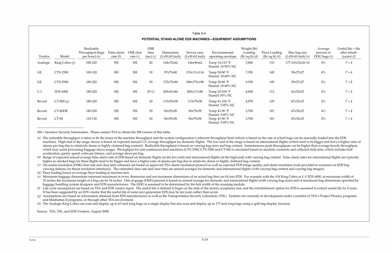
TSA506 5-19
Table 5-4
POTENTIAL STAND-ALONE EDS MACHINES—EQUIPMENT ASSUMPTIONS
Vendor Model
Realizable Throughput (bags
per hour) (a) False alarm
rate (b) OSR clear
rate (c)
OSR time
(sec) (c) Dimensions
(LxWxH inch) Service area
(LxWxH inch) Environmental
operating envelope
Weight (lb) Loading
(lb/sq ft) (d) Floor Loading (lb/sq ft) (d)
Max bag size (LxWxH inch) (e)
Average percent of
OOG bags (e)
Useful life + life after refurb.
(years) (f)
Analogic King Cobra (g) 180-220 SSI SSI 20 144x72x62 144x96x62 Temp 14-113 °F Humid. 10-95% NC
5,800 133 177/63x32x26 (h) 4% 7 + 4
GE CTX-2500 100-120 SSI SSI 30 97x75x80 133x111x116 Temp 50-80 °F Humid. 10-60% NC
7,350 145 39x27x27 4% 7 + 4
GE CTX-5500 180-220 SSI SSI 30 172x75x80 188x175x108 Temp 50-80 °F Humid. 10-60% NC
9,350 145 39x27x27 4% 7 + 4
L-3 3DX 6000 180-220 SSI SSI 20 (i) 208x81x86 208x117x86 Temp 32-104 °F Humid. 85% NC
8,600 112 62x32x25 4% 7 + 4
Reveal CT-800 (g) 180-220 SSI SSI 20 113x55x58 113x79x58 Temp 41-104 °F Humid. 5-85% NC
4,878 129 47x32x25 4% 7 + 4
Reveal CT-80DR 180-220 SSI SSI 30 96x55x58 96x79x58 Temp 41-90 °F Humid. 5-85% NC
3,700 101 47x32x25 4% 7 + 4
Reveal CT-80 110-130 SSI SSI 30 96x55x58 96x79x58 Temp 41-90 °F Humid. 5-85% NC
3,700 101 47x32x25 4% 7 + 4
SSI = Sensitive Security Information. Please contact TSA to obtain the SSI version of this table.
(a) The realizable throughput is taken to be the lesser of the machine throughput and the system configuration’s inherent throughput limit (which is based on the rate at which bags can be manually loaded into the EDS machine). High-end of the range shown is based on expected annual U.S. average throughput for domestic flights. The low-end of the range is based on international flights (which tend to be bigger and have a higher ratio of alarms per bag due to relatively dense or highly cluttered bag content). Realizable throughput is based on varying bag sizes and bag content. Instantaneous peak throughputs can be higher than average hourly throughput, which may assist processing baggage micro-surges. Throughput for non-continuous feed machines (CTX-2500, CTX-5500 and CT-80) is calculated based on machine constants and collected field data, which includes belt acceleration, gantry speed, software latency, and average slices per bag.
(b) Range of expected annual average false alarm rate of EDS based on domestic flights (at the low-end) and international flights (at the high-end) with varying bag content. False alarm rates for international flights are typically higher as checked bags for these flights tend to be bigger and have a higher ratio of alarms per bag due to relatively dense or highly cluttered bag content.
(c) On-screen resolution (OSR) clear rate and clear time estimates are based on approved TSA alarm resolution protocol as well as expected EDS image quality and alarm resolution tools provided to screeners on EDS bag viewing stations (or threat resolution interfaces). The estimated clear rate and clear time are annual averages for domestic and international flights (with varying bag content and varying bag images).
(d) Floor loading based on average floor loading at machine feet. (e) Maximum baggage dimensions represent maximum in every dimension and not maximum dimensions of an actual bag that can fit into EDS. For example with the AN King Cobra or L-3 3DX 6000, at maximum width of
32 inches the maximum height of a bag can be 14 inches. Out-of-gauge (OOG) percent is based on annual average for domestic and international flights (with varying bag sizes) and of maximum bag dimensions specified by baggage handling system designers and EDS manufacturers. The OOG is assumed to be determined by the belt width of the scanning module.
(f) Life-cycle assumptions are based on TSA and EDS vendor input. The useful life is defined to begin on the date of the factory acceptance test, and the refurbishment option for EDS is assumed to extend useful life by 4 years. It has been suggested by an EDS vendor that the useful life of some next generation EDS may be ten years rather than seven.
(g) Assumptions are based on information obtained from EDS manufacturers as well as the Transportation Security Laboratory (TSL). Systems are currently in development under a number of TSA’s Project Phoenix programs and Manhattan II programs, or through other TSA involvement.
(h) The Analogic King Cobra can scan and display up to 63 inch long bags on a single display but also scan and display up to 177 inch long bags using a split bag display function.
Source: TSA, TSL, and EDS Vendors, August 2008.

Planning Guidelines and Design Standards for Checked Baggage Inspection Systems Version 2.0 January 30, 2009 5-20 TSA506

Planning Guidelines and Design Standards for Checked Baggage Inspection Systems Version 2.0 January 30, 2009 5-21 TSA506
5.1.5 System Type 5: Stand-Alone ETD Systems
ETD equipment is currently used for primary screening (as an alternative to EDS screening and as a means to screen oversize, fragile, and other baggage that cannot be screened using EDS) and for resolution of EDS alarms. This section describes ETD systems for both applications.
5.1.5.1 Primary Screening
Stand-alone ETD equipment can currently be used for 100% screening in lobbies, baggage make-up areas, or other appropriate locations. Baggage is screened using a TSA-approved protocol for primary screening. For security and operational reasons, the BSIS Working Group recommended that TSA deploy EDS to all Category X, I, II, and III airports as part of the BSIS Working Group Report issued to ASAC on August 9, 2006. ETD will therefore be used only at Category IV airports for primary screening and at other airports to screen oversize, fragile, and other baggage that cannot be screened using EDS.
Figure 5-6
SCHEMATIC VISUALIZATION OF A STAND-ALONE ETD SYSTEM

Planning Guidelines and Design Standards for Checked Baggage Inspection Systems Version 2.0 January 30, 2009 5-22 TSA506
As ETD screening is the most labor-intensive screening method and has the lowest throughput compared with all other methods, ETD is only appropriate at small airports with low baggage volumes. A stand-alone ETD system typically has a throughput on the order of 33 BPH per screener (66 BPH per ETD machine shared by two screeners). This throughput is known to be achievable with current equipment, such as the GE Itemizer II, Smiths Detection IONSCAN 400B, or Thermodetection EGIS II.
5.1.5.2 Alarm Resolution
In addition, ETD equipment is used to screen EDS alarmed bags that have not been cleared by screeners using an OSR protocol (based on viewing bag images). This method is referred to as directed trace (or directed search using ETD) and is focused on identifying and locating alarm objects within baggage (that have triggered EDS alarms). A typical throughput using this method is 24.2 BPH per screener (a national average based on a mix of international and domestic bags of varying sizes, types, and content).
For some mini in-line configurations, a more staff efficient method of using directed trace can be achieved by using a combined OSR/ETD method. A typical throughput when using a combined OSR/ETD method is 34.5 BPH per screener if an EDS with a Baggage Viewing Station (BVS) such as Reveal CT-80 with ImageNet, is used for primary screening or 45.3 BPH per screener if an Analogic King Cobra or Reveal CT-800 is used for primary screening (see Table 5-3).
Table 5-5 summarizes equipment assumptions for ETD machines.

Planning Guidelines and Design Standards for Checked Baggage Inspection Systems Version 2.0 January 30, 2009 5-23 TSA506

Planning Guidelines and Design Standards for Checked Baggage Inspection Systems Version 2.0 January 30, 2009 5-24 TSA506
5.2 EDS CERTIFICATION PROCESS
TSA supports EDS development through multiple processes, but is most significantly involved in the final stages of EDS development when EDS equipment needs to be assessed and approved. Assessment and approval are under the auspices of the Transportation Security Laboratory (TSL) under two separate consistency assessments. The first is System Qualification Testing (SQT), which includes vendor-accomplished developmental testing and is not detection-related. The second is a detection-related conformity assessment, which depends primarily on TSL testing and consists of a Certification Readiness Test (CRT) and the formal Certification Test.
5.2.1 Non-Detection Related Assessments
Prior to SQT, the TSL reviews, witnesses, and approves vendor Developmental Test and Evaluation (DT&E) at the vendor’s plant. Following the DT&E, the TSL would conduct SQT involving selected demonstrations conducted at the TSL site for non-detection requirements, such as operability, reliability, usability, safety, communications, interfaces with conveyor controls, data loggers, training kits, information security, maintainability, emissions compatibility and susceptibility, and environmental factors.
On average, the SQT phase takes approximately 30 calendar days to complete.
After successful completion of SQT, the TSL would conduct separate tests to verify detection requirements (i.e., CRT and the Certification Test), as discussed in the following section.
5.2.2 Detection-Related Assessments
The CRT is a detection requirements conformance test, which is a condition for entry into formal Certification Testing. During the CRT, TSL and vendor personnel interact as an integral part of the EDS development process. The CRT is a relatively large and complex test design aimed at detecting specific algorithm deficiencies using a large number of unique test states.
On average, the CRT takes approximately 90 calendar days to complete.
The formal EDS Certification Test is a relatively smaller test design for measuring detection, false alarm, and throughput performance against TSA’s EDS Certification Standard. The Certification Test consists of two parts: the Preliminary Certification Preparatory Test (referred to as “Pre-Cert”) and the formal Certification Test. The Pre-Cert takes approximately 2 weeks for system/test set-up, test-operator training, system safety checks, a test dry-run, and a coarse test to check that it is performing as expected by the vendor. Based on Pre-Cert results, an EDS may be deemed not ready for a formal Certification Test and would be required to reenter the CRT process. If an EDS is deemed ready, the formal Certification Test takes 2 days to measure the detection rates and 1 day to measure the false alarm and throughput

Planning Guidelines and Design Standards for Checked Baggage Inspection Systems Version 2.0 January 30, 2009 5-25 TSA506
rates (assuming the throughput rate is in the range of 500 BPH; test duration is longer for EDS of lower throughput).
Completing the full detection-related conformity assessment typically requires several attempts. Experience with new EDS machines has shown that approximately 3 attempts and as many as 12 attempts may be required to complete this phase.
5.3 STATUS OF FUTURE TECHNOLOGIES
At the date of publication of these PGDS, the current known status of several future technologies referenced in this document is as follows:
The Analogic King Cobra (AN KC) is in certification testing and expected availability is Q4 FY 2009
The Analogic XLB (AN XLB) is in an operational hardening phase and in certification testing. Expected availability is Q4 FY 2009.
The Reveal CT-800 has recently conducted data collection at TSL. Certification is anticipated in early CY 2009 with availability in mid CY 2009 after field testing and pilots.
The GE CTX-9800 is in CRT. Expected availability is in Q4 FY 2009.
The SureScan X1000 is in prototype stage and is in continued data collection process. Targeted availability is unknown at this point.
Additional non-certified platforms (known as SG/FSSS) may become available at an unknown future date.
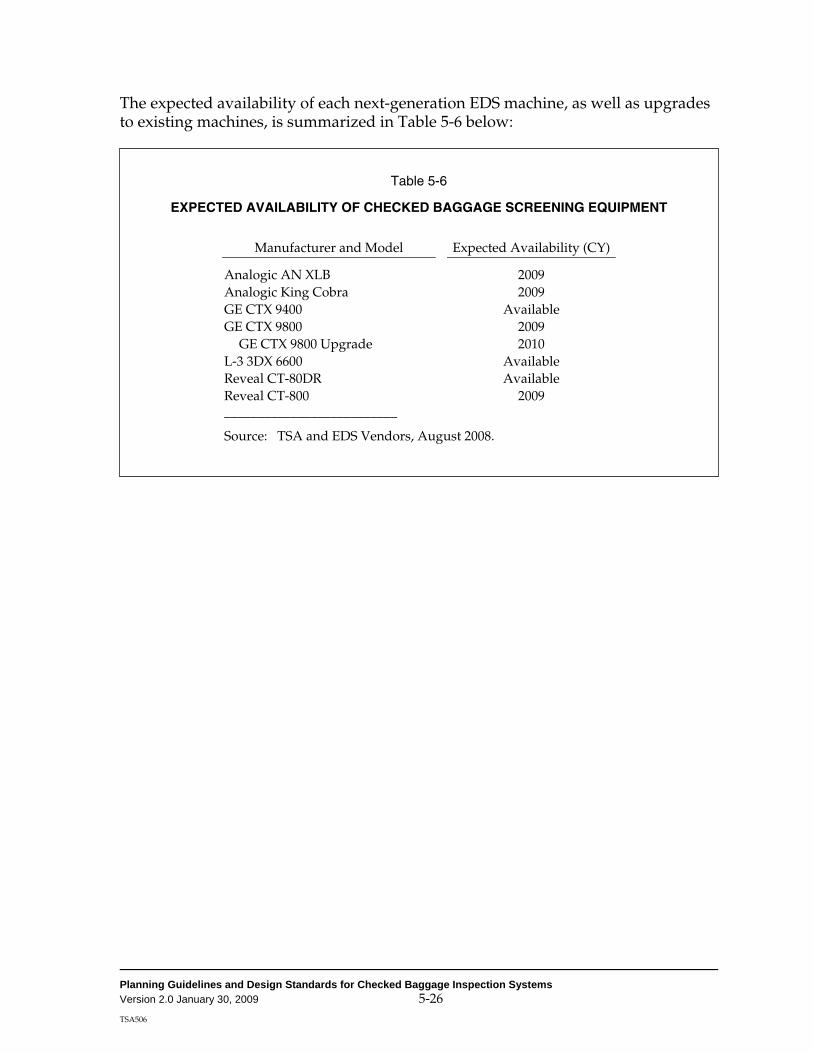
Planning Guidelines and Design Standards for Checked Baggage Inspection Systems Version 2.0 January 30, 2009 5-26 TSA506
The expected availability of each next-generation EDS machine, as well as upgrades to existing machines, is summarized in Table 5-6 below:
Table 5-6
EXPECTED AVAILABILITY OF CHECKED BAGGAGE SCREENING EQUIPMENT
Manufacturer and Model Expected Availability (CY)
Analogic AN XLB 2009 Analogic King Cobra 2009 GE CTX 9400 Available GE CTX 9800 2009
GE CTX 9800 Upgrade 2010 L-3 3DX 6600 Available Reveal CT-80DR Available Reveal CT-800 2009 __________________________
Source: TSA and EDS Vendors, August 2008.

Planning Guidelines and Design Standards for Checked Baggage Inspection Systems Version 2.0 January 30, 2009 6-1 TSA506
Chapter 6
BAGGAGE SCREENING DEMAND
This chapter documents the methodology to determine the design demand required to size optimal screening system(s) within an airport terminal. As explained in detail in the following paragraphs, the steps below summarize the methodology:
1. Divide an airport terminal into screening zones 2. Match the appropriate airlines to the zones 3. Select a design base flight schedule 4. Generate the base checked baggage demand 5. Project the base checked baggage demand to the design year
This methodology is meant only for the Pre-Design phase of the project when the focus is on equipment sizing, rather than on system performance. During later phases of design, simulation is required to refine equipment requirements and evaluate system performance. As such, detailed design-day flight schedules that reflect the best information available regarding future demand levels will be required.
Appendix C provides a case study on how these initial steps should be completed.
6.1 CATEGORIZATION INTO SCREENING ZONES
Checked baggage screening systems can be designed to combine checked baggage from several airlines into a single system. As numerous options are available for combining baggage flows, planners should use their best judgment to capture (1) high-level architectural constraints and (2) airline operational constraints. It is recommended that more than one screening configuration and airline grouping be considered at the outset of a project to provide realistic alternatives for comparison.
One approach that could be used to determine feasible combinations of baggage flow is a zone hierarchy scheme that represents the spatial characteristics of airport terminals. Figure 6-1 shows a sample scheme for a tri-level hierarchy (F1, F2, and F3).

Planning Guidelines and Design Standards for Checked Baggage Inspection Systems Version 2.0 January 30, 2009 6-2 TSA506
Figure 6-1
ZONE HIERARCHY REPRESENTATION
Each element in the hierarchy represents a spatially feasible zone for an EDS screening system, be it at a small, decentralized level or at a large, consolidated level:
F1 Zone Definition—An F1 zone is the largest feasible zone in a terminal for a centralized in-line system. These zones may accommodate multiple airlines that share an EDS screening system and are usually served by multiple baggage belts with sortation functionality downstream from the screening area.
F3 Zone Definition—On the other end of the spectrum, an F3 zone is the smallest feasible zone in the terminal where a highly decentralized EDS is likely to be preferred and is usually served by a single take-away baggage belt. A dominant airline in a terminal with multiple baggage belts would have a number of F3 zones.
F2 Zone Definition—An F2 zone represents a screening solution that fits somewhere between the F1 and F3 zones, and is usually determined by the feasibility of two or more adjacent airlines sharing their screening and baggage handling facilities (e.g., a common baggage make-up area).
For example, Figure 6-2 shows the western half of the ticketing lobby and associated baggage make-up area at Albuquerque International Sunport (ABQ). The ticket lobby, ATOs, and baggage make-up areas are all located on one contiguous level.
F1F1zonezone
F1F1zonezone
F2F2zonezone
F2F2zonezone
F2F2zonezone
F2F2zonezone
F3F3zonezone
F3F3zonezone
F3F3zonezone
F3F3zonezone
F3F3zonezone
F3F3zonezone
F3F3zonezone
F1F1zonezone
F1F1zonezone
F2F2zonezone
F2F2zonezone
F2F2zonezone
F2F2zonezone
F3F3zonezone
F3F3zonezone
F3F3zonezone
F3F3zonezone
F3F3zonezone
F3F3zonezone
F3F3zonezone
Airport Terminal

Planning Guidelines and Design Standards for Checked Baggage Inspection Systems Version 2.0 January 30, 2009 6-3 TSA506
Figure 6-2
ASSUMED SCREENING ZONES AT ALBUQUERQUE INTERNATIONAL SUNPORT
One potential method of developing a zone hierarchy for ABQ would be the following:
F3 Zones: Each take-away belt is assigned to an F3 zone.
F2 Zones: Take-away belts that are all located within an existing, contiguous make-up area are defined in this example as a single F2 zone.
F1 Zones: Since the ticketing lobby, the ATO, and baggage make-up areas are physically divided by the entrance hall into west and east sides, each side is designated as a single F1 zone. It would be impractical and expensive to screen all bags in a single centralized system for the entire airport; thus, at ABQ, two separate F1 zones were identified.

Planning Guidelines and Design Standards for Checked Baggage Inspection Systems Version 2.0 January 30, 2009 6-4 TSA506
Since the subdivision of a terminal into zones is subjective, a detailed explanation of the reasons that a particular terminal screening zone hierarchy was selected over another hierarchy should be provided as part of the Preliminary Alternatives Analysis Report (see Chapter 3).
The screening zone selection is fundamental in generating baggage screening demand profiles and, ultimately, in determining the required baggage screening equipment, as explained in the following paragraphs.
6.2 CHECKED BAGGAGE FLOW GENERATION
The purpose of this section is to explain the methodology to be used to derive existing checked baggage flows for each screening zone. For the purposes of deriving screening equipment requirements, the ADPM shall be used as the design day.
The ADPM is to be used as the design day to ensure that systems are designed to meet average-day conditions in the peak month, with the understanding that contingency plans are in place, as discussed in Chapter 8. Where designing for the ADPM does not provide sufficient capacity given the agreed-upon contingency plans, alternative design days can be used with TSA approval.
The following paragraphs describe the key inputs necessary to derive the baggage flows for the ADPM.
6.2.1 List of Airlines
All airlines (including charter airlines) operating in each of the screening zones should be identified.
6.2.2 Determination of the ADPM per Screening Zone
To identify the ADPM, it is necessary to first identify the peak month and then the average day in terms of originating bags as well as international recheck bags for each zone.
For each screening zone, the total number of monthly originating bags and international recheck bags for all airlines in that zone should be calculated. The month with the maximum number of originating and international recheck bags is the peak month.
For each screening zone, the total number of daily originating and international recheck bags for all airlines in that zone during the peak month should be calculated, and a mathematical average should be derived. The day on which the number of originating and international recheck bags is closest to the calculated mathematical average is the ADPM.
Depending on the airlines operating in each particular zone, the ADPM might differ from zone to zone.
Planning Guidelines and Design Standards for Checked Baggage Inspection Systems Version 2.0 January 30, 2009 6-5 TSA506
Planners should include charter airline originating bags or international recheck bags if relevant and available when determining the ADPM for each particular zone.
6.2.3 Flight Schedule
Once the ADPM for each zone has been identified, a design-day flight schedule for each screening zone should be obtained. These flight schedules should only contain information on nonstop flights from the study airport. Flight schedules should specify for each flight: destination, flight departure time, flight number, published carrier, operator, aircraft type, and number of seats.
In addition, to derive international recheck baggage demand, it is necessary to know the arrival schedule of international flights whose passengers will connect to domestic flights. Baggage arriving from international destinations where security screening protocols differ from those used by TSA must be re-screened at the first United States port of entry before being loaded on any domestic flight.
6.2.4 Airline Load Factors
A load factor is the percentage of seats on a flight occupied by ticketed passengers. Load factors vary by flight (e.g., by airline, time of day, and destination), by day of the week, and by season. Extensive surveys conducted at airports nationwide and data obtained from domestic and international carriers show that peak-day load factors vary from 20% to 100%. Because of the wide variance in load factors, it is important to obtain the most accurate data that reflect the specific conditions of the selected ADPM directly from the airlines whenever possible.
In addition, load factors on international arrival flights must be obtained to derive international recheck baggage demand.
6.2.5 Origin/Destination and Connecting Passenger Percentages
Originating passengers are passengers whose itinerary begins at the airport under study; an originating passenger checks in with his/her airline and proceeds through the security checkpoint to the departure gate. Similar to load factors, the percentage of originating passengers may vary by flight (e.g., by time of day, destination, and airline), by day of the week, and by season.
Domestic flights departing prior to 9 a.m. have significantly higher percentages of originating passengers than those departing after 9 a.m. due to the nature of connecting passenger traffic. In general, the first arrival bank of domestic flights permits very few passengers to connect to flights departing from the airport prior to 9 a.m.; therefore, most of the passengers on those flights are originating passengers. Thus, the percentage of originating passengers before 9 a.m. is close to 100%, after 9 a.m., the percentage ranges anywhere from 5% to 100%.
Because of the wide variance in originating passenger percentages, it is important to obtain the most accurate data that reflect the specific conditions of the ADPM directly from the airlines whenever possible.

Planning Guidelines and Design Standards for Checked Baggage Inspection Systems Version 2.0 January 30, 2009 6-6 TSA506
In addition, the percentage of passengers arriving on international flights and connecting to domestic flights must be obtained to derive international recheck baggage demand.
The estimated number of originating passengers is calculated using the number of seats, the load factor, and originating percentage assumptions for the ADPM.
Estimated Number of Originating Passengers = Seats x Load Factor x Percentage of Originating Passengers
The estimated number of connecting passengers from international to domestic flights is calculated using the number of arriving seats, the load factor, and connecting percentage assumptions for the ADPM.
Estimated Number of Connecting Passengers from International to Domestic Flights = Seats x Load Factor x Percentage of Connecting Passengers
6.2.6 Earliness Distributions
An earliness distribution specifies the percentage of passengers that arrive at the airport a specific number of minutes before their flights. The earliness distributions are used to determine the flow of departing passengers at the airport. There are significant differences in the earliness distributions among:
Passengers on flights departing for domestic versus international destinations
Passengers on flights departing before 9 a.m. and after 9 a.m.
Earliness distributions for flights departing before 9 a.m. generally are of shorter duration and thus more peaked; therefore, it is important to use the appropriate earliness distributions to accurately derive actual baggage flows.

Planning Guidelines and Design Standards for Checked Baggage Inspection Systems Version 2.0 January 30, 2009 6-7 TSA506
Figure 6-3 shows example earliness distributions for domestic carriers; as shown, the distribution for flights departing before 9 a.m. exhibits higher peaking characteristics and has a much shorter duration than the distribution for flights departing after 9 a.m.
Figure 6-3
EXAMPLE EARLINESS DISTRIBUTIONS BEFORE AND AFTER 9 A.M.
0%
2%
4%
6%
8%
10%
12%
14%
16%
0 20 40 60 80 100
120
140
160
180
200
220
240
Minutes prior to flight departure
Perc
enta
ge o
f dep
artin
g pa
ssen
gers
Domestic (before 9 a.m.)Domestic (after 9 a.m.)

Planning Guidelines and Design Standards for Checked Baggage Inspection Systems Version 2.0 January 30, 2009 6-8 TSA506
Table 6-1
EXAMPLE EARLINESS DISTRIBUTION
Sector Domestic International
Time of day After 9 am Before 9 am After 9 am Before 9 am
0 to 10 0.0% 0.0% 0.0% 0.1%
10 to 20 0.4% 0.4% 0.2% 1.2%
20 to 30 1.7% 1.7% 1.0% 3.6%
30 to 40 3.9% 3.9% 2.5% 6.5%
40 to 50 6.3% 6.3% 4.4% 8.9%
50 to 60 8.3% 8.3% 6.2% 10.4%
60 to 70 9.7% 9.7% 7.7% 10.9%
70 to 80 10.2% 10.2% 8.6% 10.5%
80 to 90 10.0% 10.0% 9.1% 9.6%
90 to 100 9.3% 9.3% 9.0% 8.3%
100 to 110 8.2% 8.2% 8.5% 7.0%
110 to 120 7.0% 7.0% 7.7% 5.6%
120 to 130 5.8% 5.8% 6.8% 4.5%
130 to 140 4.7% 4.7% 5.9% 3.5%
140 to 150 3.7% 3.7% 5.0% 2.6%
150 to 160 2.9% 2.9% 4.1% 2.0%
160 to 170 2.2% 2.2% 3.3% 1.5%
170 to 180 1.7% 1.7% 2.7% 1.1%
180 to 190 1.2% 1.2% 2.1% 0.8%
190 to 200 0.9% 0.9% 1.6% 0.5%
200 to 210 0.7% 0.7% 1.3% 0.4%
210 to 220 0.5% 0.5% 1.0% 0.3%
220 to 230 0.3% 0.3% 0.7% 0.2%
230 to 240 0.2% 0.2% 0.6% 0.1%
Total 100% 100% 100% 100%

Planning Guidelines and Design Standards for Checked Baggage Inspection Systems Version 2.0 January 30, 2009 6-9 TSA506
Figure 6-4 shows example earliness distributions for domestic and international carrier flights after 9 a.m.; as shown, the distribution variance for international carriers is higher than for domestic carriers and international passengers tend to arrive at the airport earlier.
Figure 6-4
EXAMPLE EARLINESS DISTRIBUTIONS FOR DOMESTIC AND INTERNATIONAL CARRIERS
Where possible, it is recommended that earliness distributions reflecting the specific conditions of the ADPM be obtained directly from the airlines.
6.2.7 Lateness Distributions
A lateness distribution specifies the percentage of passengers that exit the Federal Inspection Services (FIS) facility a specific number of minutes after their flights have landed. Specifically, the lateness distribution is applied to international recheck passengers that need their bags screened. Passengers arriving from international destinations where security screening is not conducted according to TSA protocols and connecting to domestic flights need to have their bags screened at the first port of entry into the United States before they are loaded onto any domestic flight. Lateness distributions have a much shorter duration than earliness distributions because all passengers deplane upon arrival within a relatively short period for a
0%
2%
4%
6%
8%
10%
12%
0 20 40 60 80 100
120
140
160
180
200
220
240
Minutes prior to flight departure
Per
cent
age
of d
epar
ting
pass
enge
rs
Domestic (after 9 a.m.)International (after 9 a.m.)

Planning Guidelines and Design Standards for Checked Baggage Inspection Systems Version 2.0 January 30, 2009 6-10 TSA506
0%
2%
4%
6%
8%
10%
12%
14%
16%
18%
0 10 20 30 40 50 60 70 80 90 100
110
120
Minutes after international flight arrival
Perc
enta
ge o
f con
nect
ing
pass
enge
rs fr
om
inte
rnat
iona
l to
dom
estic
flig
hts
given flight. For this reason, the international recheck baggage flows show marked peaks and have very short durations, as shown in the example on Figure 6-5.
Figure 6-5
EXAMPLE LATENESS DISTRIBUTION
6.2.8 Checked Bags per Passenger
The average number of checked bags per originating passenger varies by airline, by destination, and by time of year. Extensive in-field data collection efforts and specific data provided by the airlines demonstrate that the actual numbers of checked bags per passenger are lower than the common “rules of thumb” of 1.5 bags for domestic flights and 2.0 bags for international flights used by many planners and designers. Generally, data collection efforts have shown that a more reasonable range is 0.95 to 1.00 bag per passenger for domestic airlines serving business markets, 1.00 to 1.15 bags per passenger for domestic airlines serving leisure markets, and 1.35 to 1.45 bags per passenger serving international markets (including international recheck passengers). These are very generic ranges, and planners should obtain specific values for the type of carriers and markets whenever possible. Planners should consider that recent protocol modifications prohibiting and subsequently limiting liquids in carry-on baggage may also affect these ratios.

Planning Guidelines and Design Standards for Checked Baggage Inspection Systems Version 2.0 January 30, 2009 6-11 TSA506
The estimated number of originating bags is calculated using the estimated number of originating passengers and the checked bags per passenger assumptions for the ADPM:
Estimated Number of Originating Bags = Estimated Number of Originating Passengers x Number of Checked Bags per Passenger
The estimated number of international recheck bags is calculated using the estimated number of connecting passengers from international to domestic flights and the international recheck bags per passenger assumptions for the ADPM:
Estimated Number of International Recheck Bags = Estimated Number of Connecting Passengers x Number of International Recheck Bags per Passenger
The earliness and lateness distributions are used to derive the flows of originating and international recheck bags throughout the day. It is recommended that baggage flows be reported in 10-minute bins.*
Table 6-1 summarizes several potential sources of the key input data used to derive ADPM baggage flows.
Table 6-2
SUMMARY OF INPUT DATA NEEDS AND POTENTIAL DATA SOURCES
Data Source(s)
Scheduled airline activity Official Airline Guides, Inc. Airport Airlines
Charter airline activity Airport Charter airlines
Airline boarding load factors U.S. Department of Transportation Airlines
Percentage of originating passengers U.S. Department of Transportation Airlines
Earliness and Lateness distributions Airlines In-field surveys
Checked bags per passenger Airlines In-field surveys
*10-minute bins (or increments) are recommended to ensure that sufficient capacity is provided to handle baggage flows with TSA’s goal of a 10-minute incremental service standard.

Planning Guidelines and Design Standards for Checked Baggage Inspection Systems Version 2.0 January 30, 2009 6-12 TSA506
6.2.9 Calibration of Flight Schedule-Driven Demand
It is recommended that, whenever possible, planners obtain actual baggage counts from all airlines that operate at the screening zones being considered for CBIS design. The above-mentioned methodology for generating baggage flows (using flight schedules, load factors, origin/destination percentage, earliness/lateness distributions, and ratio of bags per passenger) should be calibrated with the actual baggage counts of the relevant airlines. If a significant discrepancy in peak hour baggage flow (for the ADPM) is found between the two sources, then planners should consult with the ILDT (see Chapter 3) to resolve the discrepancy.
6.3 FUTURE BAGGAGE FLOW PROJECTIONS
The baggage flows derived using the process explained in the previous paragraphs represent the ADPM baggage flows for a particular screening zone in the base year. Baggage flows must be projected to a specific design year before they can be used to determine screening equipment requirements.
6.3.1 Design Year for Equipment Requirements
The design year for equipment requirements is assumed to be 5 years after the opening year for a given baggage screening system (i.e., DBU + 5 years). This assumption is based on current TSA policy for system approval. Thus, if a system is scheduled to become operational in 2008, the design year for that system will be 2013.
Baggage flow projections can be based on the Federal Aviation Administration’s (FAA’s) Terminal Area Forecast (TAF) or on the specific airport’s master plan forecast (if the master plan is current). In general, the FAA must approve the forecast used to project design year baggage flows. If, for any reason, local airport and airline staff and their consultants believe that the TAF or the master plan forecasts do not properly represent expected growth at the airport, a revised forecast and a detailed explanation of the reasons that the FAA-approved forecast is not acceptable should be provided to TSA for approval.
The growth rate from the TAF or master plan forecast may be uniformly applied to the current baggage flow, thus preserving current activity patterns, or applied differently if a detailed explanation of the reasons that the current activity pattern is expected to change is provided.
The methodology explained above is appropriate to initially size screening systems during the Pre-Design phase of a project. However, during the more detailed phases of design, it is recommended that simulation be used to refine equipment requirements and to evaluate system performance. Simulation analyses typically require development of a more detailed design-day flight schedule.

Planning Guidelines and Design Standards for Checked Baggage Inspection Systems Version 2.0 January 30, 2009 6-13 TSA506
6.3.2 Accommodating Traffic Growth after the Design Year
The equipment requirements documented above are based on a design demand for 5 years beyond the system opening date (i.e., DBU + 5 years). It is likely that the initial system will have some excess capacity (e.g., equipment requirements are rounded up and therefore equipment will not necessarily reach 100% utilization after 5 years). This excess capacity should be used to accommodate as much traffic growth as possible before additional costs are incurred.
While increased system utilization may accommodate some additional demand, designers should also seek to provide low-cost flexibility options in the system to incorporate one or more of the following capacity enhancements:
1. Upgraded software and/or hardware to improve throughputs of installed equipment.
2. Reduced bag spacing to improve throughput of continuous-feed EDS equipment.
3. Replacement of installed equipment with higher-volume machines and necessary modifications to the BHS to support these machines.
4. Additional new equipment and associated BHS infrastructure.
In practice, a combination of one or more of the above approaches could be used. The choice of how additional capacity is provided will depend on the constraints of the terminal, degree of certainty about future traffic growth, the overall capacity of the terminal, and the optimal system type.
To accommodate future growth, some designs may require additional marginal upfront investment in conveyors or facilities. This additional investment can significantly lower long-term costs. For example, if expansion space is provided upfront instead of expanding space incrementally (as needed to accommodate growth beyond DBU + 5), then significant future savings could be achieved. As another example, when designing a medium-volume full in-line system, if the CBIS were designed so that it could accommodate high-volume EDS machines, then significant future savings (capital as well as O&M) may again be achieved where growth can be met by a relatively simple replacement of the medium-volume EDS machines.
The preferred screening alternative should then be selected considering local factors (such as expected future growth, ultimate gate capacity, overall terminal capacity, expected life of the terminal facility, and screening alternatives being considered). This selection should be made on a case-by-case basis.

Planning Guidelines and Design Standards for Checked Baggage Inspection Systems Version 2.0 January 30, 2009 6-14 TSA506
Several examples of how additional capacity could be provided for specific system types are provided below:
High-Volume In-Line Systems—It is unlikely that EDS throughput will be increased beyond 1,000 BPH in the foreseeable future. Accordingly, high-volume systems should be assumed to accommodate additional demand through the provision of additional equipment and associated BHS infrastructure. Therefore, if expected traffic growth warrants, designs should be developed that preserve space for additional equipment or provide areas where low-cost modifications to facilities might be possible to install additional machines.
Medium-Volume In-Line Systems—These systems could be designed with sufficient queuing capacity, variable frequency drives, and other components to support replacement of medium-volume EDS machines with high-volume EDS machines to accommodate traffic growth. Alternatively, designs could be developed that preserve space for additional equipment or provide areas where low-cost modifications to facilities might be possible to install additional machines. The choice will depend on local traffic, spatial and operational considerations, and life-cycle cost projections.
Mini In-Line Systems—As this system type is based on minimal BHS modifications, it is likely that the BHS of a mini in-line system will not support significantly higher-throughput EDS equipment without significant modifications. Therefore, growth beyond 5 years can be accommodated by (1) new machines and associated BHS infrastructure, (2) upgrading the BHS (and possibly the EDS) to support higher throughputs, or (3) replacing the mini in-line system with a medium-volume or high-volume in-line system.
Stand-Alone Systems—Software and hardware improvements may increase system throughput (assuming that bags can be loaded into the EDS machines at a fast enough rate to fully utilize the machine). However, it is expected that additional machines will be the most likely means of enhancing capacity.
To determine when and if additional capacity will be required, baggage demand and system performance should be monitored and projected on an annual basis. Planners would then be able to anticipate the need for additional capacity and perform any necessary analyses to determine the most cost-effective approach to enhancing system capacity.
As discussed in more detail in Chapter 9, planners should conduct a 20-year life-cycle cost analysis for each screening alternative identified and the preferred alternative should be spatially feasible as well as have the lowest life-cycle cost. The life-cycle cost analysis should include an assessment of the overall costs of different approaches for accommodating growth.

Planning Guidelines and Design Standards for Checked Baggage Inspection Systems Version 2.0 January 30, 2009 7-1 TSA506
Chapter 7
BAGGAGE SCREENING EQUIPMENT REQUIREMENTS
This chapter provides a high-level methodology to determine EDS equipment requirements, OSR station requirements, and ETD screening station requirements in the Pre-Design phase as well as an overview of the approach recommended during later design phases to finalize equipment requirements.
During the Pre-Design phase, the focus is on determining how many EDS machines, OSR stations, and ETD screening stations are required, given a certain airline grouping, system type, and EDS equipment. Once all feasible screening zones (airline groupings) are determined and the baggage flow for each screening zone has been generated and projected to the design year, it is possible to determine the high-level equipment requirements for each screening zone.
7.1 REQUIREMENTS DURING THE PRE-DESIGN PHASE
During the Pre-Design phase, EDS equipment requirements, EDS equipment redundancy, OSR station requirements, and ETD screening station requirements need to be determined. For the purposes of determining EDS equipment requirements, the peak 10-minutes of the ADPM in the design year shall be used. OSR station requirements and ETD screening station requirements shall be based on the capacity of the EDS equipment.
7.1.1 EDS Equipment Requirements
The following key steps must be completed to determine EDS equipment requirements:
Group airlines into screening zones (as discussed in Chapter 6).
Project and surge design year baggage demand for each screening zone (as discussed in Chapter 6). Additional details about surging are provided in the following paragraphs of this section.
Select system type and EDS equipment (a list of systems types, including EDS equipment types and their throughputs, is provided in Chapter 5).

Planning Guidelines and Design Standards for Checked Baggage Inspection Systems Version 2.0 January 30, 2009 7-2 TSA506
Equipment requirements should not be based on average baggage flows, but rather on surged flows obtained by multiplying the average baggage flow by a zone-specific surge factor* (for each 10-minute bin). The use of a surge factor is recommended to capture the intrinsic variance of baggage demand and ensure that equipment requirements are not undersized. The following formula is used to calculate the surge factor:
xxxSF 2+
= , where SF is the surge factor and x is the 10-minute baggage flow.
Figure 7-1 shows the 10-minute baggage flow by airline for an example airport; the surged flow is shown by the red dashed line. Each airline is represented by a different color in this figure.
To calculate EDS equipment requirements, the surged peak 10-minute design year baggage flow is first converted to surged peak-hour design year baggage flow and then divided by the appropriate hourly EDS machine throughput.
For instance, the peak 10-minute flow shown on Figure 7-1 is 198 bags per 10-minutes. The surged factor applied to this flow is approximately 1.14, yielding a surged flow of 224 bags per 10-minutes or 1,357 BPH. To calculate EDS equipment requirements for a medium-volume in-line CBIS using L-3 3DX 6600 equipment at a throughput of 550 BPH (assuming domestic bags), 1,357 BPH would be divided by 550 BPH to get 2.47. Rounding up to the nearest EDS machine implies that a CBIS with 3 EDS machines is necessary, without considering redundancy (as discussed later in this chapter).
As screening systems are sized using the ADPM, there will be instances when screening demand exceeds capacity over the course of the year. Depending on the duration of the over-capacity conditions, specific contingency measures should be implemented, as described in Chapter 8. A mutually agreed upon contingency plan shall be developed by planners in collaboration with stakeholders, including airline representatives, key airport personnel, the local TSA Federal Security Director (FSD), and representatives of TSA headquarters.
*To account for random variability in the expected average flow rate, a surge factor derived from an assumed Poisson arrival process distribution is applied to the peak 10-minute baggage flow. The surge factor formula was calibrated to the 10-minute/95th percentile performance criteria (see Chapter 4) by comparing the results to those obtained using discrete-event simulation models. The surged peak 10-minute rate is then normalized to an hourly equivalent load to obtain a design hour flow rate.

Planning Guidelines and Design Standards for Checked Baggage Inspection Systems Version 2.0 January 30, 2009 7-3 TSA506
Figure 7-1 10-MINUTE ADPM CHECKED BAGGAGE FLOW
7.1.2 EDS Equipment Redundancy
Estimating EDS equipment requirements based on surged peak-hour baggage flow will provide adequate capacity during normal operating conditions. However, EDS equipment cannot be assumed to be 100% reliable. Given the central role of EDS as the primary screening technology for checked baggage inspection, redundancy must be provided to account for the possibility that EDS equipment will be inoperable during certain peak periods.
If possible, redundancy should be achieved through directing baggage to another CBIS using cross-over conveyors, assuming that demand profiles of the screening matrices are not such that their peaks occur simultaneously. The cost of implementing such redundancy measures should be evaluated and compared to costs of other redundancy measures (e.g., providing additional screening equipment).
When spatial constraints make cross-over conveyors between separate screening matrices cost-prohibitive, EDS equipment redundancy should be calculated based
Planning Guidelines and Design Standards for Checked Baggage Inspection Systems Version 2.0 January 30, 2009 7-4 TSA506
on an assessment of the number of machines necessary to maintain 99% availability of the design capacity.
The multi-year average of the availability of EDS machines installed in-field is approximately 98%, as reported by TSA*. In other words, throughout the year, any current EDS machine was operational 98% of the time. For planning purposes designers should use EDS availability (or operational percent of uptime) of 98% for any single EDS and 99% availability for multiple EDS units in a CBIS (where redundant EDS can increase overall CBIS availability).
Based on the 99% availability goal and given an individual machine availability of 98%, only one additional EDS machine is required for systems with less than seven EDS machines. For systems with seven or more EDS machines,** two additional EDS machines would be required to reach that availability goal:
If N < 7 = N + 1
If N > 7 = N + 2
Where N is the number of EDS machines, calculated by dividing the surged peak-hour design year ADPM baggage demand by the hourly EDS machine throughout.
For the purpose of calculating EDS throughput, a weighted average of the ranges provided in Tables 5-1 through 5-6 should be used (this weighting should be done according to the mix of domestic and international bags in the zone for which the EDS equipment is being considered).
Redundant equipment shall only be provided when no other lower cost redun-dancies are possible. For instance, for decentralized systems (such as mini in-line or stand-alone systems), redundancy can be provided through the use of other nearby systems. It is expected that redundant equipment will only be cost-effective for high-volume and medium-volume systems, where (1) machine downtime can have a significant effect on system performance due to the high throughput of each machine and (2) opportunities for diverting bags to another screening area are cost prohibitive.
7.1.3 OSR Station Requirements
As explained in Chapter 5, for certain system types, OSR can be centralized and remotely located; while, for other system types, OSR and ETD screening functions can be combined and performed by the same ETD screener. *Availability is based on annual data collected in-field from TSA-certified EDS
screening equipment (CTX-2500, CTX-5500, CTX-9000, and 3DX 6000). **Theoretically, for systems with 20 or more EDS machines, 3 additional EDS
machines are required to guarantee 99% system availability. However, even for highly centralized systems, the maximum number of EDS machines is likely to be less than 12.

Planning Guidelines and Design Standards for Checked Baggage Inspection Systems Version 2.0 January 30, 2009 7-5 TSA506
The degree of centralization can also vary from totally centralized OSR systems that serve the entire airport to OSR systems dedicated to each CBIS. If the system type supports a remotely located OSR system, several considerations should guide the selection of the appropriate degree of centralization for the system, including TSA staffing, space requirements, and IT infrastructure requirements.
Thus, to select the best OSR system, it is recommended that OSR options be evaluated by assessing OSR staffing needs, capital costs of IT infrastructure and building modifications, and O&M costs.
OSR system requirements shall be derived based on the non-redundant EDS capacity sized to meet baggage demand in the design year. The following key inputs are necessary to estimate OSR station requirements for remotely located OSR systems:
Total sum of redundant EDS capacity (throughput) for all EDS machines connected to the remote OSR system (Sum of ThroughputEDS).
EDS false alarm rate for the EDS equipment selected (FAEDS) (see Chapter 5).
Average OSR screening processing time, from which it is possible to derive the average OSR throughput (ThroughputOSR) (see Chapter 5).
OSARP and CBRA area space requirements should be designed based on the 10-minute ADPM checked baggage flow rate developed for the evaluation of the EDS equipment (see Chapter 7 and Figure 7-1) and take into account the queuing of images and bags.
OSARP stations should be planned as follows:
Throughput OSR = System OSR Design Time [45 second minimum]/OSR Rate
N OSR = (10-minutes ADPM bag flow rate* FAEDS)/(ThroughputOSR)
Continuing the example earlier in this section, a CBIS with 3 L-3 3DX 6600 EDS machines would need a total of 2 OSR stations [(1372 BPH * 20%)/(180 bag images per hour) = 1.52 operators, rounded up to 2 stations].
The false alarm rate shown in the above example is notional and used for illustrative purposes only. Official planning values for EDS false alarm rates are considered Sensitive Security Information. Please contact TSA to obtain this information. For the purposes of calculating the EDS false alarm rate for OSR station requirements, a weighted average of the ranges provided in Tables 5-1 through 5-5 should be used (this weighting should be done according to the mix of domestic and international bags in the zone for which the EDS equipment is being considered).

Planning Guidelines and Design Standards for Checked Baggage Inspection Systems Version 2.0 January 30, 2009 7-6 TSA506
7.1.4 CBRA Design Requirements
CBRA delivery belts must provide “baggage pick” queues that are designed to accumulate bags and automatically advance bags to the open queue, the entire length of the delivery belt. CBRA ETD stations should always be positioned to allow maximum queuing on the delivery belt prior to the screening stations and allow for future stations to be placed toward the entry point of the delivery belt. The inline system and delivery belts must be designed to prevent system die-back at maximum loads
The best designs position 1 screening station per 1 queue window.
Each screening station should be designed based on 10-mintues of work and the “target search process rates”. Screening “target search” process rates are based on the demographics of the airport and the system design, i.e.; Domestic, International, or Combination Domestic/International percentages. Delivery rate/10-min = [(10-min ADPM bag flow rate * FAeds * (1-CRosr)) / 60] *10min
Total Screening Queues (including table position) = Delivery Rate / Process Rate
Netd stations = Total Screening Queues/Target Search Process rate in 10 min [round up]
Nbelt queues = TSQ – Netd stations
Actual OSARP and CBRA equipment and staffing (TSA model driven + contingency) must be determined by TSA HQ based on “Date of Beneficial Use” data, the following information must be provided to the TSA HQ 12 months prior to system testing:
Floor plan layouts of the OSARP and CBRA areas based on the ADPM formulas
Average Week, Peak Month (Sunday to Saturday) flight schedule planned for DBU
Demographics of system supported by the OSARP / CBRA (Domestic, International, or combination domestic / international %’s)
OSR decision time designed into the system (minimum 45 seconds)
Any special considerations that may impact bag flow rates (out-of-gage %, oversize % if processed in the CBRA)

Planning Guidelines and Design Standards for Checked Baggage Inspection Systems Version 2.0 January 30, 2009 7-7 TSA506
7.1.5 ETD Screening Station Requirements
ETD screening stations are accommodated in CBRAs. In general, an ETD machine is shared between two screeners because the amount of time the ETD machine is used during the total screening process for a bag is relatively short. Thus, the ratio of ETD screening stations to ETD equipment is assumed to be 2 to 1.
As mentioned above, for certain system types, OSR can be centralized and remotely located, while, in other cases, OSR and ETD screening functions can be combined and performed by the same ETD screener.
The following key inputs are necessary to estimate ETD screening station requirements:
Total sum of redundant EDS capacity (throughput) for all EDS machines connected to the CBRA (Sum of ThroughputEDS).
EDS false alarm rate for the EDS equipment selected (FAEDS) (see Chapter 5).
OSR clear rate (CROSR) (see Chapter 5).
Average ETD screening time per screener, from which it is possible to derive the average ETD throughput per screener (ThroughputETD) (if OSR is remote) (see Chapter 5).
Average combined OSR/ETD screening time per screener, from which it is possible to derive the average OSR/ETD throughput (ThroughputOSR/ETD) (if OSR and ETD screening functions are combined) (see Chapter 5).
Depending on the selected OSR option, ETD screening station requirements are derived as follows:
Remote OSR NETD Station = (Sum of ThroughputEDS * FAEDS * (1-CROSR))/(ThroughputETD Screener)
Combined OSR and ETD screening NETD Station = (Sum of ThroughputEDS * FAEDS)/(ThroughputOSR/ETD Screener)
where NETD Station represents the minimum number of ETD stations required to screen the design year ADPM baggage screening demand.
The number of ETD machines required is calculated as:
NETD Machines = (NETD Screeners/2) rounded up to the next ETD
Continuing the example earlier in this section, a CBIS with 3 L-3 3DX 6600 EDS machines would need a total of 7 ETD stations [(3 machines * 550 BPH * 13% * 40%)/(24.2 bags per hour) = 3.54 operators, rounded up to 4 stations]. The total number of ETD machines provided would be 2 (4/2 = 4).

Planning Guidelines and Design Standards for Checked Baggage Inspection Systems Version 2.0 January 30, 2009 7-8 TSA506
Note: In determining throughput rates for combined OSR/ETD and for Directed Search using ETD, it was assumed that each screener has a dedicated viewing station. The false alarm rate shown in the above example is notional and used for illustrative purposes only. Official planning values for EDS false alarm rates are considered Sensitive Security Information. Please contact TSA to obtain this information. For the purposes of calculating the EDS false alarm rate for OSR station requirements, a weighted average of the ranges provided in Tables 5-1 through 5-5 should be used (this weighting should be done according to the mix of domestic and international bags in the zone for which the EDS equipment is being considered).
7.2 EQUIPMENT REQUIREMENTS DURING THE SCHEMATIC AND DETAILED DESIGN PHASES
As mentioned at the beginning of this chapter, during the Pre-Design phase, several conceptual screening alternatives should be evaluated in terms of life-cycle costs. Thus, the methodology used during this phase is designed to provide quick estimates of EDS, OSR, and ETD screening requirements for each alternative concept. As explained in previous paragraphs, this methodology is based on baggage flow estimates and assumptions on average throughputs and false alarm rates.
Once the number of feasible alternatives is reduced and the feasible alternatives are compared based on the life-cycle cost methodologies described in Chapter 9, detailed simulation modeling is required to further evaluate the alternatives, refine equipment requirements, and evaluate system performance. Simulation modeling helps planners, architects, and CBIS designers move from high-level concepts to a more detailed design.
At the Schematic Design level, high-level flow-based modeling is still allowable to determine average time in system, refined equipment and staffing requirements. For complicated system designs, non-visual simulation modeling may prove beneficial and can be performed at the project sponsor’s discretion.
At the Detailed Design level, once the preferred screening system has been identified, visual simulation is required to (1) finalize the baggage handling and screening system detailed components (e.g., number of queuing belts, conveyor speeds, exact location of merge and diversion points, exact amount of buffering required), (2) assist baggage designers with PLC specifications and requirements, (3) refine the system performance evaluation, and (4) visualize the final design to assist with stakeholder review and approval.
Commercially available simulation packages, as well as proprietary packages, can be used for the Detailed Design phase.
Figure 7-2 summarizes the key elements of each phase and the analytical modeling approach used to assess requirements.

Planning Guidelines and Design Standards for Checked Baggage Inspection Systems Version 2.0 January 30, 2009 7-9 TSA506
Figure 7-2 APPROACH TO MODELING SYSTEM REQUIREMENTS
7.3 RECOMMENDED SIMULATION STANDARDS
When developing CBIS simulations, it is recommended that the following standards be used to verify the performance of CBIS designs and to ensure standardization of simulation development. Using commonly accepted standards during simulation development will enable more efficient utilization of simulation results and help implement better screening solutions.
PRE-DESIGN• Multiple concept alternatives• Future protocols and technologies• Airline groupings by screening zones• Evaluation of concepts
PRE-DESIGN• Multiple concept alternatives• Future protocols and technologies• Airline groupings by screening zones• Evaluation of concepts
SCHEMATIC DESIGN• More detailed analysis of
preferred alternatives• Travel time estimates and
equipment requirements• Evaluation of alternatives
SCHEMATIC DESIGN• More detailed analysis of
preferred alternatives• Travel time estimates and
equipment requirements• Evaluation of alternatives
DETAILED DESIGN•Preferred alternative validation•3D visualization (if needed)•Detailed system performance
optimization
DETAILED DESIGN•Preferred alternative validation•3D visualization (if needed)•Detailed system performance
optimization
QUALITATIVE AND HIGH-LEVEL QUANTITATIVE ASSESSMENTS
QUALITATIVE AND HIGH-LEVEL QUANTITATIVE ASSESSMENTS
HIGH-LEVEL FLOW-BASED MODELINGHIGH-LEVEL FLOW-BASED MODELING
SIMULATION MODELINGSIMULATION MODELING
PRE-DESIGN• Multiple concept alternatives• Future protocols and technologies• Airline groupings by screening zones• Evaluation of concepts
PRE-DESIGN• Multiple concept alternatives• Future protocols and technologies• Airline groupings by screening zones• Evaluation of concepts
SCHEMATIC DESIGN• More detailed analysis of
preferred alternatives• Travel time estimates and
equipment requirements• Evaluation of alternatives
SCHEMATIC DESIGN• More detailed analysis of
preferred alternatives• Travel time estimates and
equipment requirements• Evaluation of alternatives
DETAILED DESIGN•Preferred alternative validation•3D visualization (if needed)•Detailed system performance
optimization
DETAILED DESIGN•Preferred alternative validation•3D visualization (if needed)•Detailed system performance
optimization
QUALITATIVE AND HIGH-LEVEL QUANTITATIVE ASSESSMENTS
QUALITATIVE AND HIGH-LEVEL QUANTITATIVE ASSESSMENTS
HIGH-LEVEL FLOW-BASED MODELINGHIGH-LEVEL FLOW-BASED MODELING
SIMULATION MODELINGSIMULATION MODELING

Planning Guidelines and Design Standards for Checked Baggage Inspection Systems Version 2.0 January 30, 2009 7-10 TSA506
7.3.1 General Standards
The following standards and methodology should be used for any simulation being developed:
Begin with a layout of the system, including accurate conveyor lengths, equipment used, and belt speeds.
Program system control logic, including transfers, merges, belt speeds, and bag spacing designed for the EDS equipment being used.
Use airline passenger lists that can be generated from flight schedules with earliness distributions applied to the flight schedule to determine input into the simulation model for the specific airport. Designers shall list all data and assumptions used in the simulation model, such as arrival curves and growth factors.
For systems using laser scanners, assume a no-read or misread rate of 8.0%. For systems using radio frequency identification (RFID) scanners, assume a no-read or misread rate of 1.5%.
Identify potential locations for jams throughout the system and program in an overall 0.5% jam rate to occur randomly at the identified locations.
7.3.2 Statistical Distributions
Whenever possible, planners should obtain specific and updated ETD and OSR processing distributions from TSA. However, if these distributions are not available, the following distributions can be used:
Time to clear bag jams – Use a triangular probability distribution to simulate clearing of jams with a minimum time value of 0.5 minute, most likely time value of 1.5 minutes, and maximum time value of 5.0 minutes.
OSR protocol for EDS alarmed bags – Use a Gamma distribution where the mean is 30.0 seconds, the standard deviation is 7.5 seconds, the minimum value is 5.0 seconds and the maximum value is 45.0 seconds.
ETD protocol for oversized bags – Use a Gamma distribution. Distribution parameters are considered Sensitive Security Information. Please contact TSA to obtain information.
ETD Directed Search of EDS alarmed bag – Use a Gamma distribution. Distribution parameters are considered Sensitive Security Information. Please contact TSA to obtain information.
If possible, baggage size (length, width, and height) should be distributed based on data collection at the airport or data provided by the airport or

Planning Guidelines and Design Standards for Checked Baggage Inspection Systems Version 2.0 January 30, 2009 7-11 TSA506
airlines. When actual data are unavailable, the following conservative distribution of baggage size is recommended:
– 35% of baggage is of medium size, with the following average dimensions: 24 inches x 24 inches x 12 inches (width x length x height).
– 61% of baggage is of large size, with the following average dimensions: 24 inches x 36 inches x 18 inches (width x length x height).
– 4% of baggage is long or very large (e.g., golf bags) with the following dimensions: 24 inches x 54 inches x 24 inches (width x length x height).

Planning Guidelines and Design Standards for Checked Baggage Inspection Systems Version 2.0 January 30, 2009 7-12TSA506
[THIS PAGE INTENTIONALLY LEFT BLANK]

Planning Guidelines and Design Standards for Checked Baggage Inspection Systems Version 2.0 January 30, 2009 8-1 TSA506
Chapter 8
CONTINGENCIES
This chapter summarizes the contingency planning process, contingency plan development, and an evaluation of contingency alternatives. Appendix E provides a sample contingency plan, showing how contingency design principles are applied during the CBIS design process.
8.1 CONTINGENCY PLANNING PROCESS
Design of any CBIS shall include contingency plans for instances when baggage demand exceeds CBIS capacity, whether as the result of the failure of CBIS components or peak baggage flow that exceeds the maximum capacity of the CBIS, and for instances where alarm bags at the CBRA are defined as suspect bags (i.e., they cannot be cleared using directed search with ETD) and would need to be placed in the threat containment unit (TCU) for further inspection by law enforcement officer (typically from a bomb disposal squad).
CBIS design teams and other stakeholders, such as airports, airlines, TSA FSD, TSA headquarters, and all other relevant federal, state, and local authorities, shall mutually develop a set of agreeable mitigation measures within a comprehensive contingency plan during the design process. Design criteria associated with rapid recovery from a critical failure within the CBIS should be established within a range of technological and procedural solutions applicable at the individual screening zone level.
The initial contingency plan shall be reviewed by the full ILDT and included as an attachment to the Basis of Design Report. The contingency plan shall be reviewed by TSA as part of the overall design review and approval process for that CBIS design.
8.2 GENERAL CONSIDERATIONS
When developing a contingency plan, the CBIS design team should consider the following:
Roles and responsibilities of the various stakeholders regarding system operation during all contingency scenarios (e.g., approval of various mitigation methods and approving entities).
Overall processing capacity of the CBIS and expected occurrences of baggage flow demand exceeding CBIS capacity (e.g., during known peaks of the year that may exceed the ADPM flow).

Planning Guidelines and Design Standards for Checked Baggage Inspection Systems Version 2.0 January 30, 2009 8-2 TSA506
Set of eligible mitigation methods as approved by TSA and applicable for the particular CBIS design (taking into account relevant spatial and operational constraints at the particular airport).
Maintenance of baggage screening and conveyance operations during critical EDS failures and/or mission critical components of the BHS within the context of the screening system automation continuum and the wide variation in associated costs, both capital and operational. Contingency planning should address critical failures along a continuum that ranges from the installation of additional automation to baggage screening mitigation processes. The trade-off between capital investment and O&M costs should be analyzed in detail.
Other contingency plans that may affect checked baggage, such as Airport Operations Emergency Response Plan, local standard operating procedures (SOP) for transportation security incidents, Airport Emergency/Incident Response Plan, and Airport Emergency/Incident Recovery Plan.
Temporary alternative screening location for baggage. If CBRAs are to be used for alternative screening, they should be sized to accommodate the temporary alternative screening operations.
Threat evacuation and associated impact on baggage screening.
Natural disaster impact on the screening operation.
8.3 DESIGN RECOMMENDATIONS TO FACILITATE CONTINGENCY PLANNING
Contingency plans should be customized to the specific CBIS design and terminal constraints. Several design features can be incorporated to provide for improved operation during failure events.
8.3.1 Equipment Redundancy
Redundancy can be applied to the design of CBIS to minimize single points of failure that can severely limit the operation of the conveying system. Some level of redundancy is critical for larger capacity systems when the nearest alternate conveying system for the rerouting of baggage is prohibitively remote or nonexistent. The higher capacity system design templates discussed in this document include the provision of increased redundancy.
However, the increased cost and area requirements associated with providing the additional conveying equipment necessary for redundancy must be balanced with the potential savings of labor and time that will result during periods of equipment failure. While CBIS designers should be concerned with minimizing single points of failure, the complete elimination of all single points of failure is likely to be cost prohibitive and provide minimal additional reliability. Designers must take care to

Planning Guidelines and Design Standards for Checked Baggage Inspection Systems Version 2.0 January 30, 2009 8-3 TSA506
provide an appropriate level of redundancy based on a proper assessment of the operational and economic implications of various failure scenarios.
8.3.2 Programming Logic
In the event that one or more EDS machines (depending on the size of the CBIS) experience equipment failure, the system should be programmed so that a certain percentage of bags can be diverted directly to ETD to avoid excessive dieback situations (where baggage is being gradually accumulated back to the take-away belts and the check-in ticket counters) and maintain throughput volumes during peak periods. The percentage of diverted bags depends on the overall processing capacity of the working EDS machines. When the BHS is able to monitor the bag input rate into the screening zone and ascertain that the maximum input rate does not exceed overall screening system capacity, bags can be diverted to the operational EDS machine(s). Designers should program the system to divert baggage as required to maintain throughput and avoid dieback
8.3.3 Out-of-Gauge Diverter—Bypass to ETD
The CBIS should be configured with a BMA that will identify baggage with dimensional characteristics (height, width, or length) that the screening equipment does not have the capability to accommodate. OOG baggage should be automatically diverted to ETD for manual screening. This conveyor line requires access to standby power to function during power outages.
In the event that conveying or screening equipment failures occur down-line of the OOG divert, the OOG diverter may be programmed to operate in a “limited operation” mode in which all baggage is conveyed directly to ETD for manual screening (this added functionality must be coordinated with local TSA to determine operations).
8.3.4 Provision for Manual Conveyance of Baggage
CBIS design should allow for a clear, securable path for manual conveyance of baggage to the manual screening area. Designs should provide for manual conveyance of bags from the ticket lobby to the screening area. As much as possible, designs should make use of dedicated conveyors (preferably with access to standby power), such as crossover conveyors and OOG conveyors. CBIS analysis and design must account for the likelihood of increased staffing levels (and the associated labor expense) necessary to maintain a system that lacks mechanical mitigation measures to accommodate equipment failures.
8.3.5 Emergency and Standby Power
If there is no access to standby power for manual screening (using ETD), baggage cannot be processed using conventional ETD screening protocols. The design team should consider, at a minimum, the provision of standby or emergency power to support full manual screening using ETD.

Planning Guidelines and Design Standards for Checked Baggage Inspection Systems Version 2.0 January 30, 2009 8-4 TSA506
8.4 ALTERNATIVE TSA SCREENING MEASURES
While the design recommendations above can be used to reduce the operational and security impact of equipment failures, certain long-duration failures or failures that occur during peak periods may necessitate the application of alternative TSA screening measures. Planners should consult with TSA regarding the use of mutually agreeable alternative screening measures and document how such measures would be implemented if used as part of the contingency plan.
8.5 FAILURE TYPES AND MITIGATION MEASURES
This section describes baggage handling and screening equipment failures along with examples of potential mitigation strategies that could be used based on the duration of the failure.
Two principal factors cause the failure of CBIS—power failures produced by external events and conveying and/or screening equipment failures. For the purposes of contingency planning, the cause of a failure is of less importance than its duration. Failures can be classified based on their duration or based on the recovery period during peak times or non-peak times.
Mitigation measures are used to overcome various CBIS failures by the application of mechanical and/or manual methods (for example additional conveyers to allow appropriate transfer of baggage or backup power sources for BHS sections). In addition, as a last resort, alternative screening measures can be used with TSA approval to mitigate CBIS failures.
8.5.1 Short-Duration Failures
Short-duration failures (also referred to as non-critical failures) are failures lasting less than 10 minutes. Typically, during this class of failure, a CBIS cannot perform its function, but the failure can be cured without maintenance personnel being called. In the event of short-duration failures, airport and TSA protocols generally follow the logic that the CBIS will be returned to operation quickly.
Typical mitigation measures for short-duration failures include the following:
Freeze Situation until System Restarts. In the event that the system could restart momentarily, cleared bags may remain in place, alarmed bags may remain in place (if the alarm status is positively maintained), and bags with unknown status are manually conveyed to the CBRA. Unscreened baggage would remain in place within the system. Checked baggage would be held for induction into the CBIS until after the system restarts.
Manual Conveyance. In the event of uncertainty regarding short term re-start or when freezing the situation is not an option (e.g., if the failure occurs in the middle of a peak period), cleared bags may be manually conveyed to bag make-up. Alarmed bags, as well as bags with unknown status, are manually conveyed to the CBRA. Unscreened baggage would

Planning Guidelines and Design Standards for Checked Baggage Inspection Systems Version 2.0 January 30, 2009 8-5 TSA506
remain in place within the system. Checked baggage would be held for induction into the CBIS until after the system restarts.
8.5.2 Medium-Duration Failures
Medium-duration failures (also known as critical failures) are failures lasting longer than 10 minutes, but less than 2 hours. Typically, during this class of failure, critical components of a CBIS stop performing their function and maintenance personnel are necessary to fix these failed components. In the event of medium-duration failures, airport and TSA protocols will vary, depending on the availability of power.
Typical mitigation measures for medium-duration failures include the following:
Manual Conveyance. When the BHS is not operational, cleared baggage is manually conveyed to bag make-up. Unscreened baggage, alarmed baggage, and baggage with unknown status is sent to another EDS machine in a separate CBIS (if possible) or manually conveyed to an area designated by TSA for manual and/or alternative screening.
Use of Dedicated Conveyors with Standby Power. If a limited-operation conveyance system exists, it can be used to convey baggage to the CBRA and/or another area designated by TSA for manual screening (e.g., OOG conveyor(s) and oversize conveyor(s)). When the limited operation conveyor system is available (temporary power-loss for entire BHS, but limited system can run using a standby power source), cleared baggage will stay within the system (until system restart) or may be conveyed to bag make-up. Alarmed or unknown baggage may be conveyed to another EDS machine within a separate CBIS (if possible) or the CBRA. Unscreened baggage is conveyed to another EDS machine in a separate CBIS (if possible) or to an area designated by TSA for manual and/or alternative screening.
8.5.3 Long-Duration Failures
Long-duration failures (also referred to as catastrophic failures) are failures lasting longer than 2 hours. Typically, during this class of failure, the entire CBIS is inoperable due to power outages or major failures of critical components for an extended duration. Catastrophic failures may follow the same protocols described above for medium-duration failures. Alternate TSA screening protocols may be applied, as specified in the approved contingency plan.
Typically mitigation measures for long-duration failures are similar to those for medium-duration failures. If it is the policy of CBIS stakeholders that the airport operates during extended-duration power outages, then the design team should include in its design the provision of a limited operation conveyance system(s) with access to standby power. Power failures may also be mitigated by the use of standby power with the capacity to enable operation of the entire CBIS.

Planning Guidelines and Design Standards for Checked Baggage Inspection Systems Version 2.0 January 30, 2009 8-6 TSA506
8.6 EVALUATION OF CONTINGENCY ALTERNATIVES
When evaluating mitigation measures, planners and designers should consider a broad continuum of solutions. Common critical failures of system components (e.g., EDS unit, vertical sorter, optical scanner) within the CBIS should be analyzed to inform the selection of appropriate contingency measures. Catastrophic failures, which may involve total system failures of any duration or a component failure of long duration, should also be considered.
8.6.1 General Principles for Evaluation
The tradeoffs between providing for mechanical versus manual mitigation measures should be based on the complexity of the screening systems and the demand placed on that system. For smaller screening matrices, manual conveyance of bags to another nearby screening system or to a TSA-designated screening area for manual and/or alternative screening processes is likely to be the most cost-effective option. For larger screening systems, mechanical measures are likely to be necessary to handle the high baggage volumes processed by the system. The exact measures implemented should be evaluated based on both operational and economic (life-cycle cost) considerations. In each case, the mutually developed and approved contingency plan shall list the range of mitigation measures and the conditions that trigger those measures.
8.6.2 Mini In-Line System Example
As an example of the tradeoffs and options that should be evaluated, consider a mini in-line system with two EDS machines. Critical failure of either EDS unit or the BHS may be dealt with by relatively low-cost manual processes. The failure of a single EDS machine, however, could be mitigated by manually carrying bags to the in-feed belt serving the remaining operational EDS machine. Additionally, unscreened bags may be sent directly to the CBRA via the OOG belt. In this manner, bags are screened by ETD, with the possibility that some level of mitigation may be applied.
Alternatively, the design and operation of the two EDS-unit system could incorporate an automated feature to convey bags to a single EDS machine in the event of a critical failure of the other EDS machine. Such a feature could be included by adding a dedicated cross-over conveyor line. In this type of application, unscreened bags are diverted away from the inoperable EDS machine and merge into the input line for the remaining EDS machine. During peak periods, a logjam could result if sufficient storage capacity is not provided by the CBIS. Depending on the baggage flow for the system, the marginal costs associated with this type of failure recovery mechanism may be high relative to the marginal benefits of the solution.
In the event that both EDS machines experience medium-duration failures simultaneously, diverting bags to the CBRA would be the most effective option. A long-duration failure of the entire CBIS would require yet another mitigation process, such as increasing the number of ETD screenings and the number of screening personnel in the lobby or bag rooms prior to bag make-up for individual flights.

Planning Guidelines and Design Standards for Checked Baggage Inspection Systems Version 2.0 January 30, 2009 9-1 TSA506
Chapter 9
DEVELOPMENT AND EVALUATION OF ALTERNATIVES
Several elements of the planning process are presented together in this chapter, enabling planners to develop and evaluate alternatives of the various screening solutions for a particular airport or terminal. As discussed in previous chapters, planners should develop optimally scaled screening alternatives, taking into account the following:
Demand Data—Factors affecting checked baggage flow (see Chapter 6).
CBIS Capacity Data—Data related to the supply of security screening resources (see Chapters 5 and 7).
Airport Spatial Data—Terminal configurations, airline assignments, and architectural constraints (see Chapter 6).
Airport Capacity Data—Existing infrastructure capacities that affect current and future checked baggage flows into the CBIS, including ticket counter and curbside check-in positions, numbers of gates, and runway capacities.
Cost Data—Equipment, infrastructure, O&M, and staffing costs (see Chapter 5 as well as the following paragraphs in this chapter).
Planners are encouraged to develop various alternatives based on the specific conditions of the airport. Spatially and operationally feasible alternatives should be evaluated on the basis of a 20-year life-cycle cost analysis for implementing, maintaining, and replacing the screening systems. The lowest-cost alternative(s) that provide adequate screening solutions for the particular airport or terminal in question shall be selected as the preferred screening alternative(s).
The methodology for developing alternatives, assumptions for assessing the cost effectiveness of the alternatives, and the evaluation process for selecting the preferred alternative(s) at the Pre-Design phase of the planning process are discussed in this chapter.
9.1 DEVELOPING ALTERNATIVES
The screening alternatives should be developed based on the airline groupings (screening zones), as defined in Chapter 6, and the system types, as defined in Chapter 5. In addition, planners should assess the tradeoffs between upfront capacity and incremental capacity at an airport.
9.1.1 Airline Grouping Assignments (Screening Zones)
As discussed in Chapter 5, checked baggage screening systems can be designed to combine baggage flows from several airlines into a single screening system. When

Planning Guidelines and Design Standards for Checked Baggage Inspection Systems Version 2.0 January 30, 2009 9-2 TSA506
defining the set of screening alternatives, planners should compare screening solutions for different combinations of baggage flows. At least two different combinations of baggage flows should be analyzed to provide a meaningful comparison (e.g., centralized zones vs. airline-specific zones).
9.1.2 Tradeoffs between Screening Systems
Several screening system types could serve demand in each screening zone. The system types defined in Chapter 5 provide different tradeoffs between upfront capital costs and recurring staffing and O&M costs, as illustrated on Figure 9-1 and summarized below:
Figure 9-1
SYSTEM TYPE COMPARISON
High-Volume in-line
Medium-Volume in-line Mini in-line EDS standalone
(d) ETD
Throughput
Infrastructure Costs
Equipment Costs
Screener Staffing
Speed to Implement
Space Required
O&M Costs
HigherLower
Larger
Faster Slower
Higher Lower
Higher Lower
Higher Lower
Slower Faster
Smaller
High-Volume in-line
Medium-Volume in-line Mini in-line EDS standalone
(d) ETD
Throughput
Infrastructure Costs
Equipment Costs
Screener Staffing
Speed to Implement
Space Required
O&M Costs
HigherLower HigherLower
Larger
Faster SlowerFaster Slower
Higher LowerHigher Lower
Higher LowerHigher Lower
Higher LowerHigher Lower
Slower FasterSlower Faster
Smaller
System Type 1: High-Volume In-Line CBIS. High-volume in-line systems are likely to be used in centralized screening zones with one or more airlines. As such, they are generally the most efficient from a machine and staff utilization perspective. However, the centralized nature of these systems may require additional sortation systems, more complex conveyor arrangements, and extensive building modifications; therefore, upfront capital investment and O&M costs are high. These systems are based on high-volume EDS machines (see Chapter 5, Table 5-1) and may contain extensive buffering space and sections of conveyor allowing for sufficient OSR time.
System Type 2: Medium-Volume In-Line CBIS. Similar to high-volume in-line systems, medium-volume in-line systems are likely to be used in

Planning Guidelines and Design Standards for Checked Baggage Inspection Systems Version 2.0 January 30, 2009 9-3 TSA506
centralized screening zones with one or more airlines. Therefore, they also tend to be efficient from a machine and staff utilization perspective. In addition, the lower machine throughput would typically require less complex conveyor arrangements and fewer building modifications. The required upfront capital investment is likely to be lower than for high-volume systems. O&M costs are also typically lower than those for high-volume systems. However, labor costs are typically higher compared with high-volume systems because the medium-volume systems are expected to be less centralized. These systems are based on medium-volume EDS machines (see Chapter 5, Table 5-2) and may contain moderate buffering space and conveyors allowing for sufficient OSR time.
System Type 3: Mini In-Line CBIS. Mini in-line systems are decentralized systems that incorporate a simpler conveyor design and require a smaller footprint. These systems are likely to be located closer to airline ticket counters and/or make-up devices. Travel times are, therefore, reduced, as is the likelihood of improper baggage sortation. However, staff and equipment utilization in a mini in-line system is typically lower than for high-volume or medium-volume systems given the lower demand placed on the system and more peaked load requirements. As a result of lower facility and conveyor modification impacts, capital and O&M costs are expected to be lower for mini in-line systems than for System Types 1 and 2 (See Chapter 5, Table 5-3).
System Type 4: Stand-Alone EDS. For facilities with very low throughput requirements or where architectural conditions may render other systems cost prohibitive, a solution based on a stand-alone EDS machine (e.g., Reveal CT-80, GE CTX-5500, or GE CTX-2500) may be the most economical. A conveyor infrastructure is not required and, therefore, no significant incremental increase in airport/airline O&M costs is expected. These systems offer an even lower capital cost on a per unit basis, but are also less efficient in terms of staff and machine utilization than System Type 3 (see Chapter 5, Table 5-4).
System Type 5: Stand-Alone ETD Systems. As discussed in the BSIS Working Group report, ETD systems will only be allowed at Category IV airports or in larger airports for oversized, fragile, or other items that cannot be screened by EDS. ETD solutions are typically deployed in lobbies or bag make-up rooms and are the most labor-intensive solutions. A conveyor infrastructure is not required and, therefore, these systems offer the lowest capital and O&M cost on a per unit basis (see Chapter 5, Table 5-5).
In most cases, centralized screening zones are likely to require a fully automated in-line system (System Type 1 or 2). Smaller in-line systems or mini in-line systems are typically better suited for more decentralized zones (such as one or more airline bag rooms). Mini in-line systems and stand-alone systems are typically better suited for highly decentralized zones. However, planners should not explicitly assume this

Planning Guidelines and Design Standards for Checked Baggage Inspection Systems Version 2.0 January 30, 2009 9-4 TSA506
relationship and need to select the optimal screening system for a zone based on the particular characteristics of the zone regardless of its level of centralization.
Planners should consider and evaluate as many screening alternatives as possible by assessing spatial, operational, and life-cycle cost considerations. To provide a potential starting point for developing alternatives, TSA has developed an integrated EDS deployment model that evaluates various screening system types at all Category X, I, II, and III airports in the nation, based on the methodologies outlined in this document. The model takes into account high-level spatial and capacity constraints at airport terminals and evaluates system types on the basis of the life-cycle costs. Planners can obtain, through TSA, the model results that pertain to the airport for which they are developing the screening system design.
As discussed below, those alternatives that are spatially and operationally feasible shall be compared based on total life-cycle costs to the airport, airlines, and TSA.
9.1.3 Tradeoffs between Upfront Capacity and Incremental Capacity
As part of the process of developing alternatives, planners should assess the tradeoffs between (1) incurring additional upfront costs to increase design flexibility for accommodating future growth in demand, and (2) accommodating growth based on modifying the initial system incrementally over the 20-year analysis period. This tradeoff analysis may indicate, for instance, that systems at critical airports (such as airline hubs) should be designed with additional space to accommodate future EDS machines.
Airport planners typically assess the capacity of functional components at an airport (e.g., ticket counters, gates, runways) to determine the ultimate capacity of the terminal. The ultimate terminal or airport capacity should be treated as the upper limit for demand estimates for the purposes of CBIS design. For example, if a 20-year demand analysis indicates that additional ticket counters and/or gates and/or runway capacity are required beyond that available in the current terminal or airport, then planners should assume that such requirements are beyond the scope of the CBIS design. Capital-intensive expansions to accommodate additional demand on other airport functional components should also include consideration of additional baggage screening capacity to accommodate future growth of baggage demand beyond the ultimate capacity considered in the CBIS design.
9.2 ESTIMATING LIFE-CYCLE COSTS
The design principles defined in the PGDS emphasize the need to define and implement the lowest-cost screening alternative for the particular airport or terminal. To establish the lowest-cost alternative, planners shall calculate the life-cycle costs of developing, maintaining, and replacing the screening systems. These costs will include costs borne by TSA as well as airports and airlines.
The analysis assumptions and life-cycle costs to consider, including capital costs, O&M costs, and staffing costs, are discussed below.

Planning Guidelines and Design Standards for Checked Baggage Inspection Systems Version 2.0 January 30, 2009 9-5 TSA506
9.2.1 Analysis Assumptions
Assumptions regarding the duration of the analysis period, the EDS and ETD equipment life expectancy, and the duration of construction period are described below.
9.2.1.1 Life-Cycle Cost Analysis Period
To provide a standardized period for assessing life-cycle costs, a 20-year total life-cycle shall be assumed based on DHS guidance to fully capture the upfront capital costs as well as recurring costs for staffing, O&M, and life-cycle replacements. The 20-year analysis period allows planners to account for: (1) screening equipment refurbishment and replacement and (2) accommodating traffic growth beyond the initial equipment design year (DBU + 5 years).
9.2.1.2 Equipment Life-Cycle
Equipment life-cycle assumptions are as follows:
EDS Equipment. The useful life of the EDS machine is assumed to be 7 years. It is possible to extend the EDS machine’s useful life by 4 additional years with refurbishment options (see specific screening equipment life-cycle assumptions in Chapter 5 and specifically Tables 5-1 through 5-6).
ETD Equipment. The useful life of an ETD machine is assumed to be 5 years. No refurbishment options are available to extend ETD machine life beyond this period.
9.2.1.3 Construction Period
It is expected that the construction period will be, on average, about 2 years for the high-volume and medium-volume in-line systems and less than 1 year for all other systems (mini in-line and stand-alone). Some stand-alone systems can be installed in an even shorter period. The exact construction period will be airport-specific and depend on the complexity of and contracting requirements for the airport. Therefore, planners should estimate appropriate construction periods for the particular airport in question.
9.2.1.4 Constant Dollar Cost
Cash flows can be expressed in real or nominal dollars. Nominal (or current) values represent the expected price that will be paid when a cost is due to be paid. These values include inflation. For instance, if a machine costs $1.0 million today and is expected to cost $1.1 million in 2008, $1.1 million is the nominal cost of the machine in 2008. Real (or constant) values are adjusted to remove the effect of inflation. In the example above, the real value of the machine is $1.0 million, whether purchased today or in 2008. Real values are used to provide consistent comparison of costs over time and shall be used to estimate all costs considered in the life-cycle analysis.

Planning Guidelines and Design Standards for Checked Baggage Inspection Systems Version 2.0 January 30, 2009 9-6 TSA506
These costs shall be based on the year in which the analysis is conducted. Therefore, no assumptions regarding cost escalation or inflation are necessary for this analysis.
9.2.2 Life-Cycle Costs to Consider
At a minimum, planners should assess the following costs in determining the overall cost of each screening alternative:
Capital Costs – Screening equipment purchase price – Screening equipment installation costs – Screening equipment refurbishment and upgrade costs – Screening equipment replacement costs – Cost of EDS removal – EDS residual value and disposal costs – Costs of required building and BHS infrastructure modifications
O&M Costs – Screening equipment maintenance costs – Screening equipment operating costs – Incremental BHS maintenance costs (including additional
maintenance personnel) – Incremental BHS operating costs
Staffing Costs – TSA screener and supervisor costs – Incremental staff associated with clearing bag jams or portering bags (if
not included in O&M costs described above)
Planners should calculate overall life-cycle costs for all alternatives based (as much as possible) on actual costs. Cost assumptions, averages, and estimates provided in this chapter should serve as a baseline to verify that actual costs are within a reasonable range. Details regarding estimation of the above costs are described in the paragraphs below.
9.2.3 Estimating Capital Costs
Capital costs to be considered include screening equipment purchase price, screening equipment installation costs, screening equipment refurbishment and upgrade costs, screening equipment replacement costs, cost of EDS removal, EDS residual value and disposal cost, and costs of required building and BHS modifications.
9.2.3.1 Screening Equipment Purchase Price
The purchase prices of existing technology equipment and assumed purchase prices of future technology should be obtained from TSA. However as a starting point planners can use the following assumed purchase prices of existing and future technology as shown in Table 9-1.

Planning Guidelines and Design Standards for Checked Baggage Inspection Systems Version 2.0 January 30, 2009 9-7 TSA506
Table 9-1
PURCHASE PRICE OF CHECKED BAGGAGE SCREENING EQUIPMENT
Vendor and Model Purchase Price Source
Analogic AN XLB $1,100,000 (e) Analogic King Cobra $350,000 (e) GE CTX 9400 $1,200,000 (a) GE CTX 9800 $1,200,000 (e) GE CTX 9800 Upgrade Obtain price
from TSA (e)
L-3 3DX 6000 $880,000 (b) L-3 3DX 6600 (formerly AN6400) $1,100,000 (d) GE CTX-5500 w/ ViewLink $880,000 (c) GE CTX-2500 $625,000 (c) Reveal CT-80DR Obtain price
from TSA (d)
Reveal CT-800 $350,000 (e) ETD (various manufacturers) $40,000 (f) __________________________
Note: Actual prices will be determined through negotiations with the vendor and will likely depend upon volume purchased.
(a) As specified in most recent GE contract. (b) As specified in most recent L-3 contract (Contract number DTSA20-03-D00928). Price
does not include networking (NEDS). (c) Assumed. TSA does not currently have plans to purchase additional units. If TSA
purchases additional units, prices will be determined through negotiations with the vendor.
(d) Anticipated cost based on initial pilot testing. Price does not include networking. (e) Based on design-to-cost estimate, discussions with the Transportation Security
Laboratory, and input from EDS vendor. (f) As observed in TSA equipment databases.

Planning Guidelines and Design Standards for Checked Baggage Inspection Systems Version 2.0 January 30, 2009 9-8 TSA506
9.2.3.2 Screening Equipment Direct Installation Costs
Direct installation costs relate to the set-up and preparation of equipment for use. The components of direct installation cost are summarized in Table 9-2.
Table 9-2
COMPONENTS OF DIRECT INSTALLATION COSTS
Equipment Labor Logistics On-Site Installation Auxiliary equipment (including hardware & software)
Program management (on-site and HQ), including technical contracts
Warehousing Site preparation
Initial spares/repair parts and consumables
Systems engineering personnel
Shipping and handling Facility modifications (construction) and design (a)
Initial training Data (training manuals, maintenance manuals, operations manuals)
Integration and multiplexing
Travel Testing & evaluation
Other __________________________
(a) Includes any on-site modifications required to install screening equipment. Does not cover expenses related to baggage handling system design and associated facilities modifications.
Direct installation costs vary significantly between configurations of the same model of EDS machine. For example, an L-3 3DX 6000 installed in a stand-alone configura-tion will cost significantly less than the same unit installed in a multiplexed arrangement (i.e., electronically linked to other EDS machines). Also a higher installation cost for a mini in-line system using L-3 3DX 6000 equipment should be assumed since there is a capability of the L-3 3DX 6000 EDS to operate at higher throughput rates compared to other mini in-line EDS units (at around 400 BPH) however, to support that a higher installation price should be assumed. Table 9-3 details the installation cost assumptions of each system type.

Planning Guidelines and Design Standards for Checked Baggage Inspection Systems Version 2.0 January 30, 2009 9-9 TSA506
Table 9-3
DIRECT INSTALLATION COST OF SCREENING EQUIPMENT
System type Installation cost per machine
High-volume in-line $425,000 Medium-volume in-line $425,000 Mini in-line $100,000 – $425,000 Stand-alone EDS $9,000 – $50,000 ETD $2,500 __________________________
Note: Stand-alone EDS installations utilizing light-weight machines do not require the same floor reinforcement as do installations of heavier stand-alone equipment.
Source: TSA, June 2005.
9.2.3.3 Screening Equipment Refurbishment and Upgrade Costs
Refurbishment extends a machine’s useful life, but does not enhance throughput or other operational capabilities, whereas an upgrade provides extended capabilities. Upgrade and refurbishment assumptions are presented in Table 9-4. Upgrades and refurbishments may take place either in the field, where the equipment is deployed, or at a warehouse or factory prior to redeployment. Some machines could be either upgraded or refurbished or both. For most types of machines, it should be assumed that upgrade and refurbishment options would provide an additional 4 years of useful life. No refurbishment options are available for ETD machines.
Planners should consult with TSA about upgrade and refurbishment options as well as the costs of those options that are available for the screening equipment being considered in the CBIS design for the particular airport.

Planning Guidelines and Design Standards for Checked Baggage Inspection Systems Version 2.0 January 30, 2009 9-10 TSA506
Table 9-4
EDS REFURBISHMENT AND UPGRADE OPTIONS
Vendor/ Model Option
Additional Useful Life
(Years) Cost
Analogic / XLB Refurbish 4 $100,000 Analogic / King Cobra Refurbish 4 $85,000 GE / CTX 2500 Refurbish 4 $85,000 GE / CTX 5500 Refurbish 4 $90,000 GE / CTX 5500 Upgrade to ViewLink n.a. $100,000 GE / CTX 5500 Refurbish + Upgrade to ViewLink 4 $175,000 GE / CTX 9000 / 9400 Refurbish 4 $100,000 GE / CTX 9000 / 9400 Refurbish + Upgrade to CTX 9800 4 $550,000 GE / CTX 9800 Refurbish 4 $90,000 GE / CTX 9800 Refurbish + Upgrade 4 $250,000 GE / CTX 9800 Upgrade Refurbish 4 $75,000 L-3 / 3DX 6000 (In-line) Refurbish + Upgrade to 6600 4 $350,000 L-3 / 3DX 6000 (Lobby) Refurbish 4 $100,000 L-3 / 3DX 6000 (Lobby) Refurbish + Upgrade to 6600 4 $350,000 L-3 / 3DX 6600 Refurbish 4 $100,000 Reveal / CT-80 Refurbish 4 $80,000 Reveal / CT-80 Refurbish + Upgrade 4 $100,000 Reveal / CT-80DR Refurbish 4 Obtain price
from TSA Reveal / CT-80DR Refurbish + Upgrade 4 Obtain price
from TSA Reveal /CT-800 Refurbish 4 $100,000 __________________________
Note: Refurbish cost is highly dependent on EDS condition at time of refurbishment and level of refurbishment required to extend machine life; actual costs could significantly vary and should be obtained from TSA. Higher throughput machines are expected to be more complex compared to lower throughput machines and therefore have higher refurbish costs. In addition, older generation machines (with older technology for various sub-modules and components) are expected to require higher refurbish costs compared to newer generation machines.
Source: Assumed based on TSA and EDS vendor input, August 2008.

Planning Guidelines and Design Standards for Checked Baggage Inspection Systems Version 2.0 January 30, 2009 9-11 TSA506
9.2.3.4 Screening Equipment Replacement Costs
Whenever it is necessary to replace screening equipment with a new type of screening equipment, it may be necessary to modify the BHS so that it can support the new machine types (if the BHS was not already designed to support the new type of screening equipment). Costs associated with the modification of infrastructure to support EDS machine replacement are presented in Table 9-5.
BHS modification costs can vary significantly among CBIS types. It is highly recommended that actual cost estimates be developed for the specific site and CBIS design rather than using the cost estimates provided herein. These cost estimates are included mainly to provide planners with a rough estimate based mostly on high-level conceptual designs.
Planners should consult with TSA regarding new machine types that should be considered as replacement options. Costs of those replacement options should be assessed by planners based on actual CBIS design and on actual modifications that are required for the BHS to be able to support the new types of EDS screening equipment.
Table 9-5
INFRASTRUCTURE MODIFICATION COSTS FOR EDS REPLACEMENT
Screening System Type Infrastructure Modification Cost per
EDS Replacement
High-volume in-line $200,000 Medium-volume in-line $133,333 Mini in-line (all equipment types) $50,000 Stand-alone $0
Source: Based on input from TSA and EDS vendors, December 2006.
9.2.3.5 Cost of EDS Removal
Prior to the replacement of EDS machines, installed EDS equipment must be removed. This removal may result in costs to access equipment in space-constrained installations, disassemble conveyor segments, and temporarily modify surrounding facilities. Planners should estimate EDS removal costs for the specific screening alternatives.
9.2.3.6 EDS Residual Value and Disposal Cost
It is assumed that the EDS residual value (at the end of useful life) is equal to the cost of disposal.

Planning Guidelines and Design Standards for Checked Baggage Inspection Systems Version 2.0 January 30, 2009 9-12 TSA506
9.2.3.7 Costs of Required Building and BHS Modifications
Facility modifications and infrastructure costs represent the majority of the upfront costs associated with implementing an in-line system. Compared with other types of security screening equipment, EDS machines require significant facility design and construction costs because of their size and weight and the need to integrate these machines into the BHS. Examples of facility modification work include:
Constructing extra baggage make-up rooms to replace existing baggage make-up areas displaced by EDS equipment.
Constructing CBRAs to provide conditioned workspace for alarm resolution screening (e.g., alarm resolution with OSR and/or ETD).
Redesigning and upgrading baggage handling system conveyors to support integration with EDS equipment.
Moving walls, partitions, and any other structural components.
Reinforcing flooring to support additional weight.
Upgrading mechanical and electrical systems (and HVAC if required).
Adding ticket counter and/or curbside check-in positions and/or gates as required to support CBIS.
Since the nature of the work will vary significantly from airport to airport and greatly depends on the type of checked baggage screening system installed, facility modification costs can vary significantly. Planners shall develop a detailed, bottom-up cost estimate for facility modification and infrastructure costs for all alternatives being considered.
Because of their high upfront capital cost and the high degree of cost variability, facility modifications and infrastructure costs represent the highest risk to overall project cost and schedule. Small percentage changes in these costs can significantly affect the life-cycle cost of a project.
For each of the screening system types, Table 9-6 enumerates the assumed average cost of facility modifications and infrastructure per EDS machine. Facility modification costs are adjusted to account for regional differences in construction costs based on the Means Construction Cost Indexes* published by Reed Construction Data. Given the high variability of this cost category, these assumed averages are provided here as a starting point only and should be refined by planners in the life-cycle cost estimation to reflect site-specific conditions.
*Reed Construction Data, Means Construction Cost Indexes, Volume 32, Number 1, January 2006.

Planning Guidelines and Design Standards for Checked Baggage Inspection Systems Version 2.0 January 30, 2009 9-13 TSA506
Table 9-6
AVERAGE COST OF FACILITY MODIFICATIONS AND INFRASTRUCTURE
System Type Average Cost per Machine Source
High-volume in-line $6,000,000 (a) Medium-volume in-line $4,000,000 (b) Mini in-line $325,000 – $1,500,000 (c) (d) Stand-alone EDS $ 25,000 (e) Stand-alone ETD $4,000 (e) __________________________
(a) Bottom-up cost estimate from template baggage handling system designs and adjusted for variation between template designs and actual installations of medium-volume in-line systems.
(b) Average of selected existing in-line installations with fully integrated EDS equipment.
(c) Facility modification and infrastructure cost per EDS depends on the level of integration with the baggage handling system.
(d) Bottom-up cost estimates of template designs and data from existing installations of mini in-line EDS machines.
(e) TSA estimates from existing installations including recent installations of reduced size and weight EDS machines at lower facility modification and infrastructure costs due to higher chances of a better fit to existing buildings.
9.2.4 Estimating O&M Costs
O&M costs to be considered include screening equipment maintenance costs, screening operating costs, incremental BHS maintenance costs, and incremental BHS operating costs.
9.2.4.1 Screening Equipment Maintenance Costs
Maintenance costs include costs for preventive and corrective maintenance, related program management, moving equipment, replenishment of spares, repair parts, shipping and handling, technical update training, data manuals, other direct expenses, dismantling, and destruction. Since spring 2005, all screening equipment maintenance contracts negotiated by TSA have been on a fixed price per unit basis. Maintenance costs for new technology equipment are assumed to also be on a fixed price per unit basis, equal to 10% of the purchase price.
Consistent with previous contracts, all EDS vendors are responsible for assuming the first year’s maintenance contracts. Typically, the first year’s maintenance cost is included in the equipment purchase price. However, in-warranty maintenance costs for the GE CTX-9000 include an additional fee of $22,642 per machine in the first year for extended hour usage (i.e., operations beyond Monday through Friday, 9 a.m. – 5 p.m.). Table 9-7 shows the maintenance unit cost assumptions based on
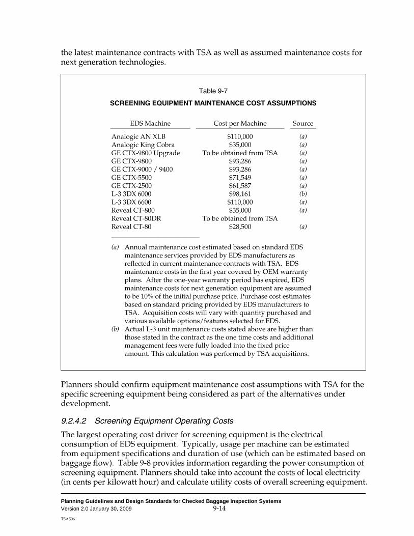
Planning Guidelines and Design Standards for Checked Baggage Inspection Systems Version 2.0 January 30, 2009 9-14 TSA506
the latest maintenance contracts with TSA as well as assumed maintenance costs for next generation technologies.
Table 9-7
SCREENING EQUIPMENT MAINTENANCE COST ASSUMPTIONS
EDS Machine Cost per Machine Source
Analogic AN XLB $110,000 (a) Analogic King Cobra $35,000 (a) GE CTX-9800 Upgrade To be obtained from TSA (a) GE CTX-9800 $93,286 (a) GE CTX-9000 / 9400 $93,286 (a) GE CTX-5500 $71,549 (a) GE CTX-2500 $61,587 (a) L-3 3DX 6000 $98,161 (b) L-3 3DX 6600 $110,000 (a) Reveal CT-800 $35,000 (a) Reveal CT-80DR To be obtained from TSA Reveal CT-80 $28,500 (a) __________________________
(a) Annual maintenance cost estimated based on standard EDS maintenance services provided by EDS manufacturers as reflected in current maintenance contracts with TSA. EDS maintenance costs in the first year covered by OEM warranty plans. After the one-year warranty period has expired, EDS maintenance costs for next generation equipment are assumed to be 10% of the initial purchase price. Purchase cost estimates based on standard pricing provided by EDS manufacturers to TSA. Acquisition costs will vary with quantity purchased and various available options/features selected for EDS.
(b) Actual L-3 unit maintenance costs stated above are higher than those stated in the contract as the one time costs and additional management fees were fully loaded into the fixed price amount. This calculation was performed by TSA acquisitions.
Planners should confirm equipment maintenance cost assumptions with TSA for the specific screening equipment being considered as part of the alternatives under development.
9.2.4.2 Screening Equipment Operating Costs
The largest operating cost driver for screening equipment is the electrical consumption of EDS equipment. Typically, usage per machine can be estimated from equipment specifications and duration of use (which can be estimated based on baggage flow). Table 9-8 provides information regarding the power consumption of screening equipment. Planners should take into account the costs of local electricity (in cents per kilowatt hour) and calculate utility costs of overall screening equipment.

Planning Guidelines and Design Standards for Checked Baggage Inspection Systems Version 2.0 January 30, 2009 9-15 TSA506
Table 9-8
SCREENING EQUIPMENT POWER CONSUMPTION
Screening Equipment Kilowatts per Hour
Analogic AN XLB 13.5 Analogic King Cobra 4.4 GE CTX 9800 Upgrade To be obtained from TSA GE CTX 9800 9.7 GE CTX-9000 / 9400 9.7 GE CTX-5500 3.0 GE CTX-2500 2.1 L-3 3DX 6000 5.5 L-3 3DX 6600 5.7 Reveal CT-80 1.6 Reveal CT-80DR To be obtained from TSA Reveal CT-800 2.5 Thermodetection EGIS II 1.7 Smiths Detection IONSCAN 400B 0.3 GE Itemizer II 0.3
Source: TSA and screening equipment manufacturers, August 2008.
9.2.4.3 Incremental BHS Maintenance Costs
In addition to EDS machine maintenance costs, costs should also account for BHS maintenance costs directly related to the CBIS. These costs typically include preventive as well as corrective maintenance to all BHS components above and beyond the current BHS maintenance costs.
For the purposes of the life-cycle cost analysis of screening alternatives, only the incremental cost of BHS maintenance shall be considered. To calculate the incremental BHS maintenance cost, planners shall subtract the existing maintenance cost of the current BHS from the total estimated maintenance cost of the BHS with CBIS.
Table 9-9 provides estimated national average costs for incremental annual BHS maintenance. However, planners should obtain accurate maintenance cost assumptions from airport personnel or the BHS operator.

Planning Guidelines and Design Standards for Checked Baggage Inspection Systems Version 2.0 January 30, 2009 9-16 TSA506
Table 9-9
ESTIMATED ANNUAL INCREMENTAL BHS MAINTENANCE COSTS
Screening System Type Incremental BHS Maintenance
Cost per EDS Machine
High-volume in-line $306,351
Medium-volume in-line $204,234
Mini in-line (all equipment types) $33,040
Stand-alone $0
Source: Data collected from existing in-line systems, May 2006.
9.2.4.4 Incremental BHS Operating Costs
Planners shall compare utility costs for the BHS on an incremental basis. To calculate the incremental BHS operating cost, planners shall subtract the existing operating cost of the current BHS from the total estimated operating cost of the BHS with CBIS.
9.2.5 Estimating Staffing Costs
Staffing costs consist of TSA screener costs as well as costs for airport/airline baggage porters. In addition, if other airport-specific staff costs are expected, these should be included in staffing or O&M costs as applicable.
9.2.5.1 TSA Screener and Supervisor Costs
TSA will assess staffing costs for TSA screeners and supervisors. Planners shall request staffing estimates for the screening alternative(s) under consideration upon submittal of the Preliminary Alternatives Analysis Report (see Chapter 3). As part of this request, planners must provide TSA with the following:
Descriptions of the screening zones (including airline groupings)
Descriptions of the screening system type and equipment for each screening zone assumed in the concept
Estimated baggage flow for the ADPM in 10-minute bins (or increments)
Assumed annual growth rate based on the forecast used to determine equipment requirements
TSA will provide estimates of the total screening cost by year for each alternative under consideration.
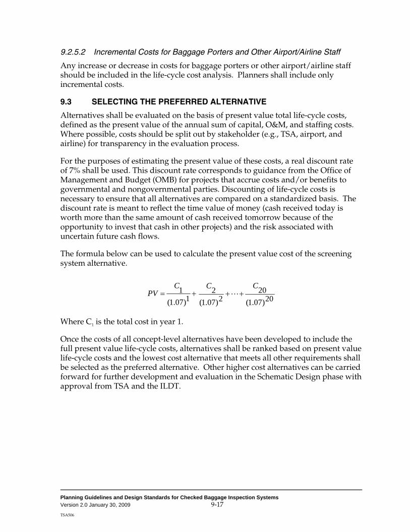
Planning Guidelines and Design Standards for Checked Baggage Inspection Systems Version 2.0 January 30, 2009 9-17 TSA506
9.2.5.2 Incremental Costs for Baggage Porters and Other Airport/Airline Staff
Any increase or decrease in costs for baggage porters or other airport/airline staff should be included in the life-cycle cost analysis. Planners shall include only incremental costs.
9.3 SELECTING THE PREFERRED ALTERNATIVE
Alternatives shall be evaluated on the basis of present value total life-cycle costs, defined as the present value of the annual sum of capital, O&M, and staffing costs. Where possible, costs should be split out by stakeholder (e.g., TSA, airport, and airline) for transparency in the evaluation process.
For the purposes of estimating the present value of these costs, a real discount rate of 7% shall be used. This discount rate corresponds to guidance from the Office of Management and Budget (OMB) for projects that accrue costs and/or benefits to governmental and nongovernmental parties. Discounting of life-cycle costs is necessary to ensure that all alternatives are compared on a standardized basis. The discount rate is meant to reflect the time value of money (cash received today is worth more than the same amount of cash received tomorrow because of the opportunity to invest that cash in other projects) and the risk associated with uncertain future cash flows.
The formula below can be used to calculate the present value cost of the screening system alternative.
20)07.1(20
2)07.1(2
1)07.1(1 CCC
PV +++= L
Where C1 is the total cost in year 1.
Once the costs of all concept-level alternatives have been developed to include the full present value life-cycle costs, alternatives shall be ranked based on present value life-cycle costs and the lowest cost alternative that meets all other requirements shall be selected as the preferred alternative. Other higher cost alternatives can be carried forward for further development and evaluation in the Schematic Design phase with approval from TSA and the ILDT.
Planning Guidelines and Design Standards for Checked Baggage Inspection Systems Version 2.0 January 30, 2009 9-18 TSA506
[THIS PAGE INTENTIONALLY LEFT BLANK]

Planning Guidelines and Design Standards for Checked Baggage Inspection Systems Version 2.0, January 30, 2009 TSA506
Appendix A
INTRODUCTION TO IN-LINE CHECKED BAGGAGE INSPECTION SYSTEMS
This appendix provides a high-level description of a typical in-line baggage inspection system using EDS units. The appendix includes a description of the way bags are directed to the screening area, the three levels of screening, and finally, the way bags are delivered to the baggage makeup device.

Planning Guidelines and Design Standards for Checked Baggage Inspection Systems Version 2.0, January 30, 2009 TSA506
[THIS PAGE INTENTIONALLY LEFT BLANK]

Planning Guidelines and Design Standards for Checked Baggage Inspection Systems Version 2.0, January 30, 2009 TSA506 A-1
Appendix A
INTRODUCTION TO IN-LINE CHECKED BAGGAGE INSPECTION SYSTEMS
The following provides a introductory description of a typical in-line CBIS, and includes a description of the way bags are directed to the screening area, the three levels of screening, and the way bags are delivered to the baggage sortation system/makeup device.
A.1 OVERVIEW
In an in-line CBIS, screening operations are integrated with the outbound baggage handling system. The screening process occurs between the point where bags are loaded onto induction belts, usually at the airline check-in counters, and the point where they are delivered to the airlines’ outbound sortation or make-up system. The process involves three different screening levels. Level 1 screening is performed with EDS units. All bags that can physically fit in an EDS unit are directed to Level 1 and scanned with EDS. All bags that automatically alarm at Level 1 are subject to Level 2 screening. During Level 2 screening, TSA personnel view alarm bag images captured during the Level 1 EDS scan, and clear any bags whose status can be resolved visually. This process is referred to as on-screen resolution (OSR), which for in-line systems allows the continuous flow of bags through the system until a decision is made. Although OSR typically occurs remotely, it may occur locally at the individual units, but this is not recommended. All bags that cannot be resolved at Level 2, and all bags that cannot be directed to Level 1 due to size restrictions, are sent to Level 3. Level 3 screening is performed manually and involves opening the bag and use of electronic trace detection ETD technology. The small percentage of bags that do not pass Level 3 screening are either resolved or disposed of by a local law enforcement officer. The following paragraphs further describe key elements of an in-line CBIS.
A.2 CONVEYOR INPUTS
Typically, checked bags originate at induction belts located on the public side of the terminal, which deliver bags from ticket counters and curbside check-in facilities to the baggage screening zone, or at international or interline recheck inputs.
Depending on the specific CBIS design, bags typically continue along the mainline conveyors to the screening zone (optionally, bags can continue over several types of load-balancing devices prior to arriving at the screening zone).
Typically, a baggage measurement array (BMA) is used to identify bags that are too large to fit into the EDS unit (defined as out-of-gauge [OOG] bags) for downstream diversion to a separate conveyor transferring the bags directly to Level 3 screening

Planning Guidelines and Design Standards for Checked Baggage Inspection Systems Version 2.0, January 30, 2009 TSA506 A-2
at the Checked Baggage Resolution Area (CBRA also known as Baggage Inspection Room or BIR) to be screened manually using ETD equipment.
A.3 LEVEL 1 – EDS SCREENING ZONE
Unscreened bags are typically sent to EDS conveyor subsystems consisting of queue conveyors in front of each EDS unit. Various methods can be used to configure BHS control logic, which drives load balancing between or among EDS units (round-robin or first-available).
When bags enter the EDS units and are screened, a decision is made by the unit, indicating whether or not the bag has generated an automatic alarm.
Bags cleared by the EDS units typically exit and transport through the Level 1 cleared-bag divert point located at a relatively close point downstream from the EDS unit.
In general, Level 1 EDS-cleared bags represent approximately a significant majority of all screened bags (exact percentages will depend on the type of EDS unit used and the average false alarm rate of that unit). Level 1 EDS-cleared bags exit the screening system fairly quickly, depending on the EDS unit location and the CBIS design.
A.4 LEVEL 2 – ON-SCREEN RESOLUTION ROOM
Bags that generate an automatic alarm by the EDS units are defined as “alarm bags” and typically continue traveling on the same conveyor until they reach a BHS decision point. If a screener decision on an alarm bag has been made by the time the bag arrives at the decision point (based on bag images sent to a remote OSR room), the bag will be diverted accordingly (as a cleared or suspect bag). If no screener decision was made, the bag status would be determined as unknown, treated as a suspect bag, and transported to the Level 3 checked baggage reconciliation/resolution area (CBRA).
During the travel time (or wait time at decision points) of bags pending OSR decision, bag images are sent to viewing stations within a remote screening room where TSA screeners view the images and determine whether the bag is clear or suspect. When a TSA screener makes an OSR decision (typically, taking an average of 30 seconds) or exceeds the maximum time allowed for viewing a bag image (typically, 45 seconds), the status of that bag (suspect or unknown) is communicated to the BHS and the EDS unit and the bag is diverted accordingly (suspicious and unknown bags to the CBRA and cleared bags to the clear bag lines or bag make-up area).
Some portion of all alarm bags viewed by TSA screeners are cleared using the currently approved OSR protocol.

Planning Guidelines and Design Standards for Checked Baggage Inspection Systems Version 2.0, January 30, 2009 TSA506 A-3
If a bag is mistracked after being screened by the EDS unit, its status becomes unknown (or mistracked) and the bag would typically be diverted to Level 3 inspection at the CBRA and be manually screened, similar to manual screening of OOG or oversize bags.
A.5 LEVEL 3 – MANUAL SCREENING WITH ETD
Bags that are not cleared by OSR screening, unknown/error bags and OOG bags are diverted to the CBRA.
When a bag arrives at the CBRA, its corresponding image is typically retrieved by the TSA screener (the image is transmitted over the EDS network) using the bag identifier (ID). Based on the bag image, the TSA screener identifies and locates the alarm object(s) within the alarm bag and manually clears the object(s) using ETD (referred to as directed trace or manual inspection).
Bags clearing ETD screening are re-inserted onto a cleared bag conveyor and typically merged with the main flow of bags to the bag sortation or make-up area.
Typically, most alarm bags (as well as unknown and OOG bags) at the CBRA are cleared using ETD directed trace.
A.6 ORDINANCE DISPOSAL
The small remainder of alarm bags that are not cleared by manual inspection at the CBRA are resolved or disposed of by a local law enforcement officer (LEO), who is usually a member of the local bomb disposal unit. These bags are loaded into a threat containment unit at the CBRA to be further inspected by an LEO. The vast majority of this small fraction of bags is cleared by the LEO.

Planning Guidelines and Design Standards for Checked Baggage Inspection Systems Version 2.0, January 30, 2009 TSA506 A-4
Figure A-1 SCHEMATIC FLOW CHART OF AN IN-LINE SCREENING SYSTEM
Source: Jacobs Consultancy, September 2006.
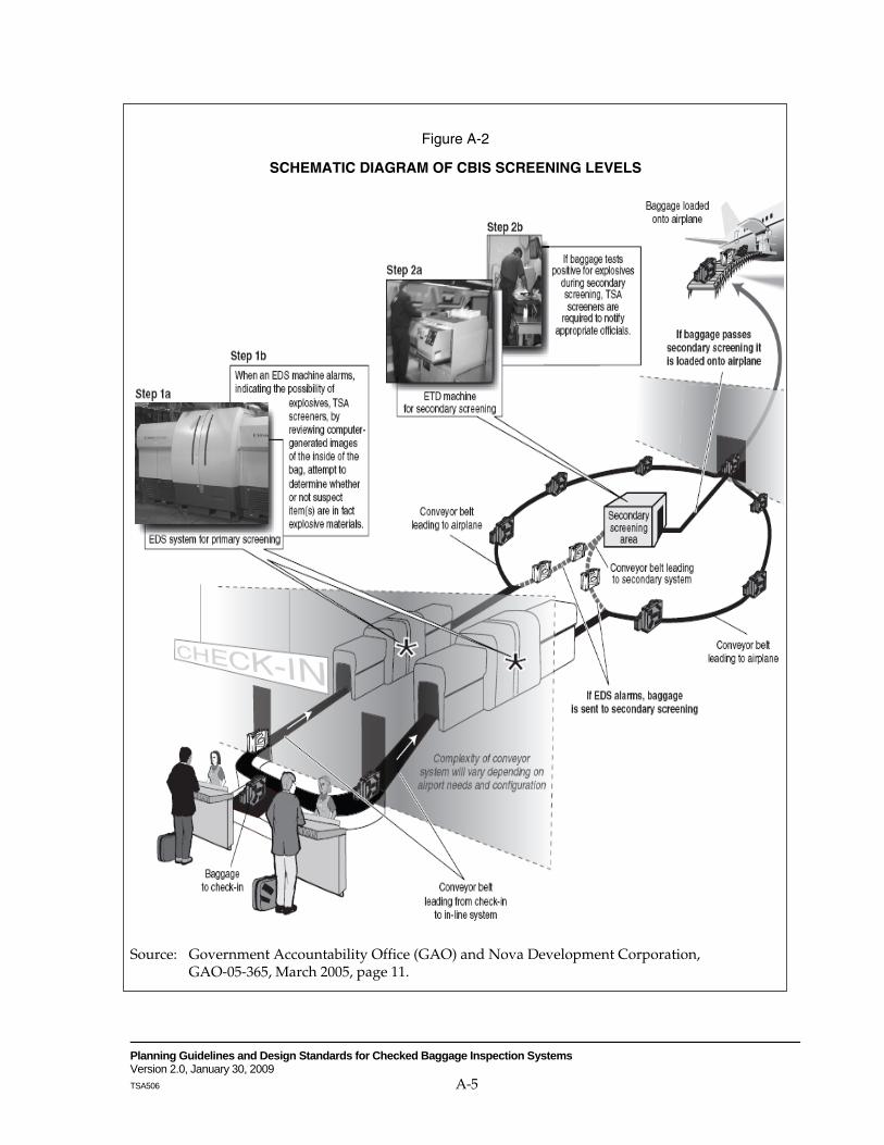
Planning Guidelines and Design Standards for Checked Baggage Inspection Systems Version 2.0, January 30, 2009 TSA506 A-5
Figure A-2
SCHEMATIC DIAGRAM OF CBIS SCREENING LEVELS
Source: Government Accountability Office (GAO) and Nova Development Corporation, GAO-05-365, March 2005, page 11.
Planning Guidelines and Design Standards for Checked Baggage Inspection Systems Version 2.0, January 30, 2009 TSA506 A-6
[THIS PAGE INTENTIONALLY LEFT BLANK]

Planning Guidelines and Design Standards for Checked Baggage Inspection Systems Version 2.0, January 30, 2009 TSA506
Appendix B
GENERIC EXAMPLES OF CHECKED BAGGAGE INSPECTION SYSTEMS
This appendix provides generic examples of various design concepts of CBISs, relevant operational assumptions for those examples, and specific best practices related to the CBIS examples.

Planning Guidelines and Design Standards for Checked Baggage Inspection Systems Version 2.0, January 30, 2009 TSA506
[THIS PAGE INTENTIONALLY LEFT BLANK]

Planning Guidelines and Design Standards for Checked Baggage Inspection Systems Version 2.0, January 30, 2009 TSA506 B-1
Appendix B
GENERIC EXAMPLES OF CHECKED BAGGAGE INSPECTION SYSTEMS
Generic examples of various design concepts of CBISs, relevant operational assumptions for those examples, and specific best practices related to the CBIS examples are provided in this appendix to supplement the information contained in Chapter 4 and Appendix D1 of the PGDS.
The high-level generic examples (i.e., examples that are not highly detailed but rather convey a concept of a screening system) are provided to assist planners at the pre-design stage of CBIS design with the development of conceptual alternatives. The examples are not site-specific and should not be used as-is. These examples are intended to serve as a starting point for planners to provide ideas on different concepts of CBIS, some of the pros and cons of each concept, and some of the best practices that relate to specific CBIS design concepts. When developing design concepts, planners should consider local operational and spatial conditions, which are likely to significantly influence the actual CBIS design concepts developed.
B.1 METHODOLOGY USED FOR DEVELOPING GENERIC EXAMPLES
Most of the following generic CBIS examples were developed and evaluated using high-volume EDS machines as the basis of design (although some were designed for low- and medium-volume EDS machines more suitable for mini in-line CBIS concepts). For most examples, a medium-volume EDS machine can be considered as an alternate to the high-volume EDS machine in applications where anticipated throughput does not justify the need for a high-volume EDS machine. Higher throughput could be accomplished in most cases by a relatively simple substitution of the EDS machines, without otherwise changing the layout of the main EDS processing system (i.e., changing BHS conveyors in the immediate vicinity of the EDS machines, bypass and purge lines, and CBRA conveyors), and without requiring changes to ticketing/curbside belts and bag make-up/sortation conveyors.
In some examples, other minor layout revisions may be required to provide a better match between BHS conveying capacity and EDS design throughput, but these revi-sions are unlikely to have much effect on BHS capital cost or building area require-ments. Planners should consider such modifications when developing specific CBIS design concepts. The substitution of a high-volume EDS machine with a medium-volume EDS machine will likely result in revised values for OSR and ETD screener staffing requirements and for the associated equipment/space requirements for this equipment and personnel.
A useful strategy may be to design a system based initially on the use of medium-volume EDS machines and subsequent replacement by high-volume EDS machines as demand increases. This strategy would provide a convenient method of

Planning Guidelines and Design Standards for Checked Baggage Inspection Systems Version 2.0, January 30, 2009 TSA506 B-2
achieving a 35% to 40% increase in system throughput capacity without requiring significant revisions to the main EDS and BHS layout (other than EDS machine substitution and additional ticketing and make-up capacity, as required).
The following assumptions were the basis for developing the generic CBIS examples:
• A separate line is used for bags too large to be loaded on the ticketing/curbside belts (e.g., surfboards, skis, and golf clubs).
• Oversize bags represent about 4% of total checked bags. These bags are screened using ETD for primary screening.
• A bypass belt is used (except in low capacity applications) to divert bags that will not fit the aperture dimensions of the EDS tunnel. The diverter directs out-of-gauge (OOG) bags directly to the CBRA, bypassing the EDS machines.
• A purge line is used in some examples to allow for the routing of bags to be automatically reintroduced into the main line feeding the EDS lines in the event of an individual EDS machine failure when necessary (see detailed discussion in Chapter 4 and Appendix D1).
• A minimum of 45 seconds is provided after the bag has been screened by an EDS machine for OSR processing in High Volume and Medium Volume CBIS designs.
The ETD/directed search processing rate was assumed to be 24.2 bph per operator (average).
All main lines delivering bags to or taking bags away from a group of EDS machines are assumed to be capable of feeding the CBIS at the minimum rate of the total screening capacity of the non-redundant combined EDS matrix.
B.2 GENERIC EXAMPLES OF LINEAR CBIS DESIGN CONCEPTS
Linear CBIS design concepts typically have a relatively straight forward linear conveyor system transporting baggage from ticket counter take-away belts to the screening zones and from the screening zones to the CBRA zone(s) and bag make-up device(s).
Five variations of linear CBIS design concepts are described below:
• Linear CBIS Design Concept A1—Baggage is transferred from ticket counters on a single conveyor to EDS, and vertical sorters or 45-degree
Planning Guidelines and Design Standards for Checked Baggage Inspection Systems Version 2.0, January 30, 2009 TSA506 B-3
diverters separate clear/alarm bags soon after the bags exit the EDS machines.
• Linear CBIS Design Concept A2—Similar to design concept A1, but baggage exits the EDS machines and are merged onto a single accumulation conveyor, pending OSR decision (i.e., alarm baggage and clear baggage are commingled).
• Linear CBIS Design Concept B1—Similar to design concept A1, but intended to handle higher volume of bags transferred from the induction lines.
• Linear CBIS Design Concept B2—Similar to design concept B1, but provides higher capacity as well as fallback redundancy with dual induction conveyors and dual conveyors leading from the screening zone to the bag make-up area.
• Linear CBIS Design Concept F3—Similar to design concept B2, but provides even higher capacity and greater fallback redundancy with triple induction conveyors and triple conveyors leading from the screening zone to the bag make-up area.

Planning Guidelines and Design Standards for Checked Baggage Inspection Systems Version 2.0, January 30, 2009 TSA506 B-4
B.2.1 Example of a Linear CBIS Design Concept A1
A conceptual layout for concept A1 is shown on Figure B-1 below.
Figure B-1 CONCEPT A1

Planning Guidelines and Design Standards for Checked Baggage Inspection Systems Version 2.0, January 30, 2009 TSA506 B-5
Description of Linear CBIS Design Concept A1. This design concept includes two ticket counter zones and one curbside check in zone. Bags are merged into a single main line conveyor belt leading to the security screening and bag make-up area. A baggage measurement array (BMA) is used to identify OOG bags that exceed the available cross-sectional area that can be accommodated by the EDS machines. OOG bags are diverted to a conveyor leading directly to the CBRA for manual inspection and clearance. All other bags proceed to a diverter that divides bag flow between the two EDS machines. After screening by EDS equipment, bags proceed to a vertisorter (a 45 degree diverter with parallel conveyors could also be configured) where alarmed bags are diverted to an accumulation conveyor, pending OSR inspection by TSA personnel.
Bags cleared by the EDS machines are immediately segregated from alarmed bags and proceed directly to a single main line delivery conveyor leading to the make-up area. There is a subsequent merge point for bags cleared by OSR or ETD. Upon reaching the end of the OSR accumulation conveyor, bags that have been cleared by TSA personnel are diverted (vertisorter or 45 degree diverter) to a cleared bag belt, which, in turn, merges with the main line delivery conveyor leading to the make-up area, as described above. Bags that are not cleared by TSA personnel (including bags for which no clearance decision has been reached by the time the bag reaches the decision point) will default to the CBRA for manual inspection.
Positive bag tracking controls are used to monitor the location of all bags processed by the EDS machines and to enable images of screened bags sent to the CBRA to be accessed by TSA screening/search personnel. EDS images are sent to the corres-ponding ETD inspection position to assist with directed ETD screening of the bag. Bags that are cleared after ETD screening/search are loaded onto a return conveyor, which merges with the main line delivery conveyor leading to the bag make up area. Any “threat” bags identified during the ETD screening/search process are loaded to a threat containment unit (TCU) for removal to a secure area for processing or are handled according to other procedures defined by local law enforcement.
Evaluation of Linear CBIS Design Concept A1. This design concept is well suited for a moderate-sized application. However, the concept may involve a high cost for EDS machines because a backup machine may be necessary to maintain operations in the event of machine failure, resulting in average machine utilization of about 50% during peak period operations when both machines are operational. An alternative solution would be to design the CBRA so that bags could be accumulated in that area and then screened using the ETD equipment at the CBRA. CBRA space and equipment requirements should be identified in light of the agreed-upon contingency plan developed by the ILDT (see Chapter 8). Separation of alarmed and cleared bags immediately downstream of the EDS machines minimizes risk of bag mistracking by diverting the majority of bags to an untracked conveyor environment, but involves some system complexity (programmable logic controller [PLC]) programming due to larger tracking zone) and cost.

Planning Guidelines and Design Standards for Checked Baggage Inspection Systems Version 2.0, January 30, 2009 TSA506 B-6
B.2.2 Example of a Linear CBIS Design Concept A2
A conceptual layout for concept A2 is shown on Figure B-2 below.
Figure B-2 CONCEPT A2

Planning Guidelines and Design Standards for Checked Baggage Inspection Systems Version 2.0, January 30, 2009 TSA506 B-7
Description of Linear CBIS Design Concept A2. This design concept is similar to design concept A1, except that the layout is simplified by having no separation of cleared and alarmed bags (although not recommended) prior to the OSR decision point. After screening by the two EDS machines, all bags are merged onto a main line conveyor. Bags not cleared by the EDS machines are inspected by TSA personnel using OSR protocols. Those bags that have initially been cleared by EDS machines or cleared by TSA OSR personnel continue on the main line conveyor leading to the bag make-up area. Bags that are not cleared by TSA personnel (including OSR bags for which no clear decision has been reached by the time the bag reaches the decision point) are diverted off of the main line conveyor and delivered to the CBRA for manual inspection. ETD screening/search is carried out as in concept A1, above.
Evaluation of Linear CBIS Design Concept A2. This design concept provides a simplified version of design concept A1, permitting installation in a somewhat smaller space (and at a lower cost). However, maintaining cleared and alarmed bags on the same conveyor for a longer period of time (around 45 seconds for OSR screening) increases the possibility of bag mistracking. This risk can be mitigated by designing the BHS control systems to ensure that any mistracked bags default to the CBRA, although the additional percentage of mistracked bags will require addi-tional screening staff. Depending on the type of system failure at a peak period, the cleared bags will not be physically separated from the alarmed bags and will require re-screening to determine their status.
Linear CBIS design concept A1 and A2 have a single main line conveyor carrying baggage from ticket counter zone to the screening zone. Linear CBIS design concept A1 and A2 share similar advantages and disadvantages.
In general, CBIS design concepts that allow for a commingling of clear and alarm bags over long conveyor section (rather than quickly separating the bags of different statuses) are not recommended.
B.2.3 Example of a Linear CBIS Design Concept B1
The conceptual layout for concept B1 is shown on page B-9.
Description of Linear CBIS Design Concept B1. This CBIS design concept has six ticket counter zones (each with 15 check-in positions) and three curbside check-in zones, from which bags are transferred and/or merged onto a single main line conveyor belt leading to the security screening and bag make-up area. A BMA is used to identify OOG bags that exceed the available cross-sectional area that can be accommodated by the EDS machines. The OOG bags are diverted directly to a conveyor leading to the CBRA for manual inspection and clearance. All other bags proceed to a diverter zone, typically consisting of three 45-degree diverters, which divide bag flow among the four EDS machines. After EDS screening, bags proceed to a vertisorter (a 45 degree diverter with parallel conveyors could also be configured) where alarmed bags are diverted and then merged onto an accumulation (OSR) conveyor pending OSR screener decision.

Planning Guidelines and Design Standards for Checked Baggage Inspection Systems Version 2.0, January 30, 2009 TSA506 B-8
Bags cleared by the EDS machines proceed directly and merge onto a single main line conveyor leading to the make-up area to be discharged to a sort system. Any bags that cannot be correctly processed because of EDS machine malfunction are diverted to a purge line leading back to the main line delivery conveyor upstream of the EDS machine zone for re-screening (see Chapter 4 and Appendix D1 of the PGDS for additional information on purge lines). Upon reaching the end of the OSR accumulation conveyor, bags that have been cleared by TSA personnel are diverted (vertisorter or 45-degree diverter) to a cleared bag belt, which, in turn, merges with the cleared bag main line conveyor leading to the bag make up area.
Bags that are not cleared by TSA personnel (including bags for which no clearance decision has been reached by the time the bag reaches the decision point) default to the CBRA for manual inspection. Positive belt tracking controls are used to monitor the location of all bags processed by the EDS machines and to enable images of screened bags sent to the CBRA to be accessed by TSA screening/search personnel to assist with directed ETD screening of the bag. Bags cleared after ETD screening/search are manually transferred onto a return conveyor, which merges with the cleared bag main line conveyor leading to the bag make-up area. Any “threat” bags identified during the CBRA process are loaded to a TCU for removal to a secure area for processing or are handled according to other procedures defined by local law enforcement.
The cleared bag main line conveyor leading to the bag make-up area, in most systems with this throughput capacity, leads to a separate sortation area, where bags are typically distributed among a number of make-up loops or piers for final sort to individual flights. This process usually requires an automatic tag reader (ATR) and manual encode spur upstream of the make-up loops or piers, as illustrated above. Sortation to individual loops or piers is typically via vertisorters or 45-degree diverters, as appropriate. The sortation component of the BHS is not included in this analysis.
Evaluation of Linear CBIS Design Concept B1. The use of multiple EDS machines increases the average peak period utilization of each machine (compared with concept A1) from about 50% to about 75%, as redundant screening equipment represents a smaller percentage of the system. However, the baggage conveying systems serving the EDS machines are more complex and costly. Linear CBIS design concept B1 depends on a single main line conveyor feeding bags to the EDS machine array and a single main line conveyor feeding bags to the make-up/sort area. Therefore, a single point of failure condition exists, and a bag jam or failure to a component of this conveyor impact bag processing. The bag throughput rate on these single conveyors is also relatively high during peak periods, requiring effective merge controls at inputs to the main line conveyors, with increased risk of bag jams and system down-time. This concept generally requires a separate sortation system downstream of the EDS/ETD screening area to sort bags by flight or by airline.

Planning Guidelines and Design Standards for Checked Baggage Inspection Systems Version 2.0, January 30, 2009 TSA513 B-9
Figure B-3
CONCEPT B1

Planning Guidelines and Design Standards for Checked Baggage Inspection Systems Version 2.0, January 30, 2009 TSA506 B-10
[THIS PAGE INTENTIONALLY LEFT BLANK]

Planning Guidelines and Design Standards for Checked Baggage Inspection Systems Version 2.0, January 30, 2009 TSA506 B-11
As in linear CBIS design concept A1, the design for concept B1 maintains the separation of clear/alarm bags; concept B1 has potentially a higher reliability compared to concepts A1 and A2 because of the additional conveyors leading to a higher number of EDS machines can compensate for EDS failure. However, as noted, the single delivery conveyor is a single point of failure.
B.2.4 Example of a Linear CBIS Design Concept B2
The conceptual layout for concept B2 is shown on page B-13.
Description of Linear CBIS Design Concept B2. This design concept is similar in functionality to concept B1, except that improved system capacity and fallback redundancy are provided by the use of dual main line conveyors delivering bags between ticketing/curbside and EDS machines, and dual cleared main line conveyors delivering bags between EDS machines and the make-up/sortation area.
Where possible, ticketing and curbside belts are arranged to achieve an approxi-mately balanced flow during the peak period to the two main line conveyors leading to the EDS screening zone. Upstream of the EDS, screening zone diverters on each of the two main line conveyors allow crossover from one main line conveyor to the other, for either load balancing and/or fallback redundancy. Each main line conveyor is equipped with a BMA to identify OOG bags that exceed the available cross-sectional area that can be accommodated by the EDS machines. These OOG bags are diverted from the two main line conveyors via a merge unit to a single conveyor leading directly to the CBRA for manual inspection and clearance. All other bags proceed to a diverter (one on each delivery belt), which divides bag flow among the four EDS machines. After level 1 screening, bags proceed to a sort point (vertisorter or 45 degree diverter) where alarmed bags are diverted and then merged onto an OSR accumulation conveyor, pending OSR inspection by TSA personnel. Bags cleared by the EDS machines proceed directly and merge onto one of two main line conveyors leading to the bag make-up area, to be discharged to a sort system. Bags that cannot be correctly processed because of an EDS machine malfunction may be diverted to a purge line leading back to the delivery belt upstream of the EDS machine zone for re-screening (see Chapter 4 and Appendix D of the PGDS for additional information on purge lines).
Upon reaching the end of the OSR accumulation conveyor, bags that have been cleared by TSA personnel are diverted (vertisorter or 45-degree diverter) to a cleared bag belt, which, in turn, merges with the main line conveyor leading to the bag make-up area. Bags that are not cleared by TSA personnel (including bags for which no clearance decision has been reached by the time the bag reaches the decision point) default to the CBRA for manual inspection. Positive belt tracking controls are used to monitor the location of all bags processed by the EDS machines and to enable images of screened bags sent to the CBRA to be accessed by TSA screening/-search personnel to assist with directed ETD screening of the bag. Bags cleared after ETD screening/search are loaded onto a single return conveyor that leads to a divert

Planning Guidelines and Design Standards for Checked Baggage Inspection Systems Version 2.0, January 30, 2009 TSA506 B-12
point to allow bags to merge with either of the two main line conveyors leading to the bag make-up area. Any “threat” bags identified during the ETD screening/-search process are loaded to a TCU for removal to a secure area for processing or are handled according to other procedures defined by local law enforcement.
The two cleared bag main line conveyors leading to the bag make-up area, in most applications, lead to a sortation area, where bags are typically distributed among a number of make-up loops or piers for final sort to individual flights. This process usually requires two ATRs and one or more manual encode spurs upstream of the make-up loops or piers. Sortation to individual loops or piers would typically be via vertisorters or 45-degree diverters, as appropriate.
Evaluation of Linear CBIS Design Concept B2. By addressing one of many single points of failure conditions that exists in concept B1, this design concept offers a measured level of improved system reliability by providing two independent routes from ticketing/curbside to the bag make-up/sortation area. This design ensures that, a significant portion of peak-period throughput capacity can be maintained even in the event of a major subsystem failure (e.g., failure or jam on a main line conveyor to one pair of EDS machines). However, it should be noted virtually all of the generic examples shown (A1, A2, B1, B2, & F3) contain many single points of failure. Further, the level of redundancy incorporated into a CBIS design should address the economical cost in order to achieve the desired level of system reliability and performance. This CBIS concept generally requires a separate sortation system downstream of the EDS/ETD screening area, to sort bags by flight or by airline. This sortation system could, in many cases, incur considerable extra expense.
Linear CBIS design concept B2 offers the added benefit of system reliability through the incorporation of the redundant main line conveyor over concept B1, but it does involve additional conveyor complexity and cost as a result of the additional main line conveyor and crossover connections required.
B.2.5 Example of a Linear CBIS Design Concept F3
The conceptual layout for concept F3 is shown on page B-15.

Planning Guidelines and Design Standards for Checked Baggage Inspection Systems Version 2.0, January 30, 2009 TSA506 B-13
Figure B-4
CONCEPT B2

Planning Guidelines and Design Standards for Checked Baggage Inspection Systems Version 2.0, January 30, 2009 TSA506 B-14
[THIS PAGE INTENTIONALLY LEFT BLANK]

Planning Guidelines and Design Standards for Checked Baggage Inspection Systems Version 2.0, January 30, 2009 TSA513 B-15
Figure B-5
CONCEPT F3
Planning Guidelines and Design Standards for Checked Baggage Inspection Systems Version 2.0, January 30, 2009 TSA506 B-16
[THIS PAGE INTENTIONALLY LEFT BLANK]

Planning Guidelines and Design Standards for Checked Baggage Inspection Systems Version 2.0, January 30, 2009 TSA506 B-17
Description of Linear CBIS Design Concept F3. This design concept uses con-ventional conveyor technology—bags are transferred from five ticket counter zones (each with two rows of 25 check-in positions) and five curbside check-in zones to three main line conveyors leading to the security screening and bag make-up area.
Crossover belts allow for diverting bags between pairs of the three delivery belts for fallback redundancy. BMAs are used to identify OOG bags, which are diverted to a conveyor leading to the CBRA. All other bags proceed to a diverter zone, consisting of five 45-degree diverters, which divide bag flow among the eight EDS machines. After screening, the bags proceed to a sort point (vertisorter) where alarmed bags are diverted and then merged onto one of two OSR accumulation conveyors, pending OSR decision. Bags cleared by the EDS machines proceed directly and merge onto the three main line conveyors leading to the bag make-up area to be discharged to a sort system. Bags that cannot be correctly processed as a result of an EDS machine malfunction can be diverted to a purge line leading back to the delivery belt upstream of the EDS machine zone for re-screening (see Chapter 4 and Appendix D of the PGDS for additional information on purge lines). Upon reaching the end of the OSR accumulation conveyors, bags that have been cleared by TSA personnel are diverted, using 45-degree diverters, to one of two cleared bag belts, which, in turn, merge with two of the main line conveyors leading to the bag make-up area. Bags that are not cleared by TSA OSR personnel (including bags for which no clearance decision has been reached by the time the bag reaches the decision point) default to the CBRA for manual inspection. Positive belt tracking controls are used to monitor the location of all bags processed by the EDS machines and to enable images of screened bags sent to the CBRA to be accessed by TSA screening/search personnel to assist with directed ETD screening of the bags. Bags cleared after ETD screening/search are loaded onto one of two return conveyors, which merge with the main line conveyors leading to the bag make-up area. Any “threat” bags identified during the ETD screening/search process are loaded to a TCU for removal to a secure area for processing, or are handled according to other procedures defined by local law enforcement.
The main line conveyors leading to the make-up area, in most applications, lead to a separate sortation area, where bags are typically distributed among a number of make-up loops or piers for final sort to individual flights. This design usually requires ATRs and a manual encode spur upstream of the make-up loops or piers. Sortation to individual loops or piers would typically be via vertisorters or 45-degree diverters, as appropriate.
Evaluation of Linear CBIS Design Concept F3. This concept has similar advantages and disadvantages to those of linear CBIS design concept B2 – concept F3 has been developed along similar lines, with additional conveyor lines and EDS machines to handle higher baggage volumes. Concept F3 is based on conventional belt conveyor/diverter technology, and would be well suited to an application where a high-capacity sortation system and bag make-up area already exists, and to which an in-line screening system needs to be added. Linear CBIS

Planning Guidelines and Design Standards for Checked Baggage Inspection Systems Version 2.0, January 30, 2009 TSA506 B-18
concept F3 involves a large number of diverters and merge units, with rather complex tracking of bags through these transition points. Without the proper implementation of positive bag tracking equipment and method, as described in Appendix D1, this system has greater potential for mistracking and/or bag jams and would also require more attention to detail in the development of the control logic to appropriately divert bags to available EDS machines according to the specified load balancing logic.
B.3 GENERIC EXAMPLES OF DECENTRALIZED CBIS DESIGN CONCEPTS
Decentralized CBIS design concepts provide dedicated EDS machines for each ticket counter bank or each ticket counter (as with decentralized concept E2). In addition, each EDS machine would typically have a dedicated CBRA in which both OSR and ETD search can be conducted. It may be that the CBRA can be combined, which would then typically require additional ATRs on the conveyor, allowing automated sortation of alarm bags cleared at the CBRA to dedicated make-up devices.
Two variations of decentralized CBIS design concepts are described below:
• Decentralized CBIS Design Concept E1—Baggage from a ticket counter bank is transferred through a single conveyor to a dedicated EDS machine.
• Decentralized CBIS Design Concept E2—Baggage from two ticket counters is manually or mechanically loaded into a dedicated EDS machine right behind the ticket counters.

Planning Guidelines and Design Standards for Checked Baggage Inspection Systems Version 2.0, January 30, 2009 TSA506 B-19
B.3.1 Example of a Decentralized CBIS Design Concept E1
A conceptual layout for concept E1 is shown on Figure B-6 below.
Figure B-6 CONCEPT E1
Description of Decentralized CBIS Design Concept E1. This concept is
configured to provide dedicated EDS machines for each check-in zone, with a back-up machine provided as a common-use unit or to provide overflow capacity. Each of the three ticketing/curbside modules would deliver bags through a BMA to a dedicated EDS machine. A diverter immediately downstream of the BMA would divert OOG bags to a bypass line leading directly to the CBRA. This bypass line can also be used in the event of failure of one of the three dedicated EDS machines to divert bags to the fourth fallback EDS machine. Positive Bag Tracking controls are

Planning Guidelines and Design Standards for Checked Baggage Inspection Systems Version 2.0, January 30, 2009 TSA506 B-20
required to differentiate between OOG bags and those that have been rerouted because of an equipment failure. OOG bags would proceed directly to the CBRA, whereas other bags would be diverted to the fallback EDS machine for EDS screening. Immediately downstream of each of the four EDS machines, a diverter would be used to deliver alarm bags to the CBRA via an OSR accumulation conveyor to facilitate OSR screening. A purge line can be also provided to route bags that cannot be processed as a result of an EDS machine malfunction can be diverted back to the fourth EDS machine (see Chapter 4 and Appendix D of the PGDS for additional information on purge lines). The diverter feeding this purge line is located immediately upstream of the CBRA.
Bags cleared by each of the three dedicated EDS machines would proceed directly to a dedicated make-up loop, allowing a relatively fast process time for the majority of bags. Bags cleared by the fourth fallback EDS machine and bags cleared by OSR or by personnel in the CBRA would be merged on a single sort line equipped with an ATR and three sort outputs leading to the three bag make-up loops. The illustration above shows this sort line terminating at the third make-up loop; in this case, any bag that fails to be read at the ATR would default to this loop, together with any bag destined for the first or second make-up loop that is not correctly sorted as a result of, for example, mistracking or diverter malfunction. In this case, personnel at the third make-up loop would be required to check bag tags and redistribute any bag that should have been sorted to the first or second make-up loop. An optional recirculation loop could be provided, as indicated by a dashed line in the illustration, to allow mistracked or otherwise unsortable bags to be returned to the upstream end of the sort conveyor for resortation. A manual encoding station is shown at the upstream end of the sort line (downstream of the ATR) to encode bags that fail to be read by the ATR.
Evaluation of Decentralized CBIS Design Concept E1. The primary advantage of this design concept is that it provides a direct and relatively fast point-to-point delivery path for the majority of bags processed with, under normal circumstances, only a small percentage of bags requiring additional processing and/or longer delivery times. The disadvantage of the layout is that it does not readily permit load balancing over all four machines.
Typically, this concept is appropriate for three separate airlines with approximately equal throughput and demand profiles, where it is desirable to operate independent systems for the majority of bags and to limit shared facilities to the minority of bags that need special handling.
This CBIS design concept also provides relatively quick separation of clear/alarm bags (similar to some linear CBIS concepts), requires simple PLC configuration, and has a relatively flexible provision for OSR view time. This concept provides a medium level of reliability as there would be only one EDS machine and transfer conveyor for each ticket counter bank and so if that dedicated EDS fails, screening of bags could be done by the fallback EDS) However, because equipment is spread out

Planning Guidelines and Design Standards for Checked Baggage Inspection Systems Version 2.0, January 30, 2009 TSA506 B-21
over a relatively larger floor area (mainly in bags rooms and Airline Ticket Office [ATO] space), challenges for rights-of-way and maintenance may result.
B.3.2 Example of a Decentralized CBIS Design Concept E2
A conceptual layout for concept E2 is shown on Figure B-7 below.
Figure B-7 CONCEPT E2

Planning Guidelines and Design Standards for Checked Baggage Inspection Systems Version 2.0, January 30, 2009 TSA506 B-22
Description of Decentralized CBIS Design Concept E2. This concept is typically configured to provide dedicated EDS machines for two or more check-in counters. Several options exist for the configuration of this design concept. One typical configuration would be to move the ticket counters forward and place EDS machines behind the counters, either parallel or perpendicular to the existing take-away belt. Depending on spatial constraints, queuing conveyors can be placed in front of the EDS machines. Baggage is loaded by passengers on the bag-well and by ticket agents or loaders onto the EDS in-feed conveyor. Alarm bags would remain at the exit of the EDS machine until an OSR decision is given by a TSA operator (which can be either local or remote). Level 3 screening is then typically conducted in a centralized CBRA (but could be done in decentralized CBRAs if economically justi-fied). Baggage is conveyed to the CBRA on an exit-integrated conveyor system with bag tracking. An ATR is located prior to the decision point on the take-away belt.
Another potential configuration (illustrations not included in this appendix) could be S-shaped, which places the EDS machine parallel to the ticket counter and take-away belt and requires that the ticket counter be moved 13 feet away from the take-away belt. A new take-away belt is installed behind the counter for bag queuing and three 90-degree turns are used to create additional queuing space prior to the EDS machine. Alternatively, when the width of the ticket counter area is constrained, the EDS machine can be placed perpendicular to the counter and take-away belt and one 90-degree turn brings bags from the new take-away belt to the machine (L-shaped).
A variation on the L-shaped configuration is a T-shaped configuration where two queuing belts can feed a single machine from opposite sides if one machine can handle the throughput but more bag queue space is required.
In another variation, the EDS machines can be placed in each ticket counter bag well and integrated at the exit with the existing take-away belt, which requires replacing the existing bag well with an in-feed conveyor that also acts as a bag scale. In this configuration, one EDS machine can service two ticket counter positions.
Evaluation of Decentralized CBIS Design Concept E2. The major advantage of this concept is that it offers high system reliability with multiple EDS machines that can be used when other EDS machines fail; however; this ultimately leads to relatively low EDS machine utilization rates. In addition, this is a relatively simple CBIS that requires a simple PLC and is relatively easy to scale to meet future demand growth (assuming no lobby spatial limitations). The main disadvantage is that this design concept has relatively increased impacts on the public ticket lobby and potential impact on overall CBIS performance based on airline staff procedures. This design concept is also susceptible to potential baggage mistracking at the decision point (for bags pending OSR decision), which has to be resolved manually. Finally, there is a relatively high degree of commingling of clear and alarm bags on the take-away belt carrying bags pending OSR decision.

Planning Guidelines and Design Standards for Checked Baggage Inspection Systems Version 2.0, January 30, 2009 TSA506
Appendix C
BASIS OF DESIGN REPORT EXAMPLE AND CASE STUDY OAKLAND INTERNATIONAL AIRPORT
Planning Guidelines and Design Standards for Checked Baggage Inspection Systems Version 2.0, January 30, 2009 TSA506
[THIS PAGE INTENTIONALLY LEFT BLANK]

Planning Guidelines and Design Standards for Checked Baggage Inspection Systems Version 2.0, January 30, 2009 TSA506 C-1
C.1 BACKGROUND
Oakland International Airport (referred to in this Report Example as “the Airport”) recently undertook a study to identify an optimally-scaled checked-baggage inspection system (CBIS) for Terminal 1, the subject of this Basis of Design Report Example.
Prior to the above-mentioned study, in the Spring of 2004, a design study had been initiated by the airport to replace an existing baggage screening system of explosives-trace-detectors (ETD) with a set of automated explosives-detection-system (EDS) machines to serve Southwest Airlines (the sole airline tenant at Oakland Terminal 2). The design concept called for a conveyor system to transfer baggage from ticket counters to an in-line EDS screening area adjacent to the terminal where EDS machines automatically screen baggage for explosives and divert false alarm and oversize baggage to a checked baggage resolution area (CBRA). Baggage cleared by the EDS machines proceeds to Southwest’s outbound baggage make-up carousel. The Terminal 2 in-line system became operational in February 2006, and that system’s in-line design study is not included in this Report example.
Key objectives for the optimally-scaled alternatives for Terminal 1 at the airport included: (1) minimizing the number of manual baggage screening operations involved and (2) improving the overall level of customer service at the Airport while maintaining 100% checked baggage screening.
Terminal 1 serves a mix of domestic air carriers and affiliated commuter operators. Currently there are three EDS machines used for screening checked baggage at Terminal 1.
United Airlines uses one stand-alone EDS machine (GE CTX-2500) located behind the airline ticket counter. Selectee bags moving along the conveyor to the United Airlines’ make-up area are manually removed and sent through the EDS machine for security screening.
JetBlue uses a semi-integrated EDS machine (GE CTX-5500) located behind the JetBlue ticket counter. A conveyor connects the ticket counters to the EDS machine. All of the JetBlue bags are first screened by the CTX-5500. Cleared bags are sent to the make-up area and alarmed bags are sent to a CBRA where alarms are resolved by TSA agents.
The remainder of Terminal 1 airlines use manual ETD screening located in the bag-gage make-up rooms. Selectee bags are manually carried to the third EDS machine (GE CTX-5500) located in the lobby, where they are screened and then sorted and manually placed on the conveyor and sent to the appropriate airline make-up room.
The Airport is achieving 100% baggage screening; however the process is labor intensive, with the majority of the bags undergoing ETD screening as opposed to

Planning Guidelines and Design Standards for Checked Baggage Inspection Systems Version 2.0, January 30, 2009 TSA506 C-2
being screened by EDS machines. The Airport wants to move ahead with an in-line EDS system to improve customer service, scalability, and airport growth oppor-tunities. In the Spring of 2006, a study was conducted to identify feasible CBIS alternatives that could be implemented at the Airport.
Terminal 1 existing conditions are shown on Figure C-1.
Figure C-1 EXISTING CONDITION
Terminal 1
C.2 EXECUTIVE SUMMARY
Optimally-scaled checked baggage inspection system (CBIS) alternatives for Terminal 1 at the Airport were identified. At the time this study was conducted, Terminal 1 served a mix of domestic airlines and their affiliated regional/commuter airlines, and the majority of bags were screened using explosives-trace-detectors (ETD) instead of explosives-detection-system (EDS) machines. To improve customer service and support Airport growth opportunities, the Port was interested in evaluating in-line bag screening alternatives. Key study objectives included: (1) minimizing the number of manual baggage screening operations and (2) improving overall customer service at the Airport while screening 100% of checked bags. Ranging from highly centralized systems with high-throughput EDS machines to more decentralized systems using lower-throughput EDS machines (mini in-line), several conceptual alternatives for in-line screening were considered.
Since Terminal 1 is designed to serve a mix of domestic and international airlines, a high-speed in-line CBIS was not feasible because of the spatial requirements and additional complexity associated with assigning bags to specific airlines after they were screened at a centralized location. Therefore, only four mini in-line CBIS alternatives were found to be operationally and spatially feasible. Within the mini in-line alternatives, Reveal CT-80 and Analogic King Cobra (AN KC) EDS machines

Planning Guidelines and Design Standards for Checked Baggage Inspection Systems Version 2.0, January 30, 2009 TSA506 C-3
were evaluated based on life-cycle cost, potential screening capacity, customer level of service, and other qualitative factors.
To support the evaluation, two models were developed. The first was a life-cycle cost model to determine the cost-effectiveness of each alternative over a 20-year period, and the second was a simulation model to evaluate screening capacity, level of service, and operational performance.
After all of the constraints were evaluated, Alternative 3, a mini in-line system of 7 AN KC EDS machines, was deemed to be the best CBIS alternative for the Airport.
C.3 CBIS ALTERNATIVES
C.3.1 Zoning Schema
As explained in Chapter 5 of the Planning Guidelines and Design Standards (PGDS), there are several ways of combining checked baggage into screening systems. Taking into consideration spatial and operational constraints, two zone hierarchy schemas were developed for Terminal 1 and are shown on Figures C-2 and C-3.
Figure C-2 ZONING SCHEMA
Terminal 1, Option A

Planning Guidelines and Design Standards for Checked Baggage Inspection Systems Version 2.0, January 30, 2009 TSA506 C-4
Figure C-3 ZONING SCHEMA
Terminal 1, Option B
For Terminal 1, the “F3 Zones” correspond to each take-away belt, while the “F1 Zone” comprises the entire terminal. At the intermediate “F2 Zone” level, there are several options to combine checked baggage into screening systems. For the purpose of this template, two options are considered for F2 Zone groupings: Option A (Figure C-2) divides the ticket counters into three groups combining checked baggage into three screening systems, while Option B (Figure C-3) divides the ticket counters into two groups combining checked baggage into two screening systems.
C.3.2 Screening System Types
As explained in detail in Chapter 5, there are several system types and EDS equipment for in-line systems, ranging from highly centralized systems using high-throughput EDS machines to very decentralized systems using low-throughput EDS machines. Since the zoning schema, the system type selection, and the demand estimation are inter-related, several iterations were necessary to find an optimally-scaled solution for each terminal. Thus, at this early stage of analysis, all spatially feasible system type options were considered and carried forward in the evaluation.
The following is a general description of potential system types for three zoning levels at Terminal 1 that were considered as initial candidates for screening alternatives:
Terminal 1, F3 Zone Groupings—For screening systems reflecting the F3 Zone groupings, decentralized system types are recommended. Thus, at F3 Zone level, mini in-line systems are acceptable options. Stand-alone EDS systems were not considered because they would present spatial constraints to any expansion that would be necessary to accommodate growth beyond the design year.

Planning Guidelines and Design Standards for Checked Baggage Inspection Systems Version 2.0, January 30, 2009 TSA506 C-5
Terminal 1, F2 Zone Groupings—At F2 Zone level, depending on the expected checked baggage demand volumes, high-throughput centralized systems, such as high-volume and medium-volume in-line systems, or lower-throughput systems, such as mini in-line systems are acceptable options.
Terminal 1, F1 Zone Grouping—At Zone 1 level, a centralized system is recommended. Thus, both high-volume and medium-volume in-line systems are acceptable options for this terminal. The choice between the two system types depends on the date of beneficial use (DBU), since that will dictate the type of EDS equipment expected to be certified by that date. Since DBU is expected to be after 2008, both high-volume and medium-volume in-line systems would be viable. If a medium-volume system is ultimately selected, all the necessary steps should be taken to make the system flexible enough to accommodate high-volume EDS machines when they become available.
C.3.3 Qualitative Assessment of Preliminary Alternatives
An initial pass of a relatively large number of alternatives was done and all alternatives that are clearly not feasible were immediately eliminated without further consideration. In this initial pass it was determined that structural and spatial constraints render any expansion or major building modification required to accommodate the in-line systems, cost prohibitive. Accordingly at Terminal 1, all of the full in-line concepts were found to be infeasible. Only the mini-in-line system type layouts designed for the F-3 Zone were found to be operationally and spatially feasible at Terminal 1.
Of the F3 Zone alternatives, the Reveal CT-80 (CT-80) and Analogic King Cobra (AN KC) EDS machines are considered to be better options for the Airport when compared to the L-3 3DX 6000 and GE CTX-5500 with Viewlink. The CT-80 and AN KC machines are considered superior products because they are newer, have better performance capabilities, and strong upgrade possibilities for the future. Therefore the L-3 3DX 6000 and GE CTX-5500 with Viewlink are also removed from further consideration.
Table C-1 provides a list of all preliminary alternatives considered and brief reason of rejecting those initial alternatives.
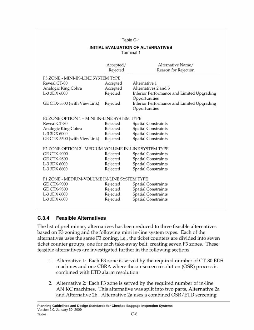
Planning Guidelines and Design Standards for Checked Baggage Inspection Systems Version 2.0, January 30, 2009 TSA506 C-6
Table C-1
INITIAL EVALUATION OF ALTERNATIVES Terminal 1
Accepted/ Rejected
Alternative Name/ Reason for Rejection
F3 ZONE - MINI-IN-LINE SYSTEM TYPE Reveal CT-80 Accepted Alternative 1 Analogic King Cobra Accepted Alternatives 2 and 3 L-3 3DX 6000 Rejected Inferior Performance and Limited Upgrading
Opportunities GE CTX-5500 (with ViewLink) Rejected Inferior Performance and Limited Upgrading
Opportunities F2 ZONE OPTION 1 – MINI IN-LINE SYSTEM TYPE Reveal CT-80 Rejected Spatial Constraints Analogic King Cobra Rejected Spatial Constraints L-3 3DX 6000 Rejected Spatial Constraints GE CTX-5500 (with ViewLink) Rejected Spatial Constraints F2 ZONE OPTION 2 - MEDIUM-VOLUME IN-LINE SYSTEM TYPE GE CTX-9000 Rejected Spatial Constraints GE CTX-9800 Rejected Spatial Constraints L-3 3DX 6000 Rejected Spatial Constraints L-3 3DX 6600 Rejected Spatial Constraints F1 ZONE - MEDIUM-VOLUME IN-LINE SYSTEM TYPE GE CTX-9000 Rejected Spatial Constraints GE CTX-9800 Rejected Spatial Constraints L-3 3DX 6000 Rejected Spatial Constraints L-3 3DX 6600 Rejected Spatial Constraints
C.3.4 Feasible Alternatives
The list of preliminary alternatives has been reduced to three feasible alternatives based on F3 zoning and the following mini in-line system types. Each of the alternatives uses the same F3 zoning, i.e., the ticket counters are divided into seven ticket counter groups, one for each take-away belt, creating seven F3 zones. These feasible alternatives are investigated further in the following sections.
1. Alternative 1: Each F3 zone is served by the required number of CT-80 EDS machines and one CBRA where the on-screen resolution (OSR) process is combined with ETD alarm resolution.
2. Alternative 2: Each F3 zone is served by the required number of in-line AN KC machines. This alternative was split into two parts, Alternative 2a and Alternative 2b. Alternative 2a uses a combined OSR/ETD screening

Planning Guidelines and Design Standards for Checked Baggage Inspection Systems Version 2.0, January 30, 2009 TSA506 C-7
function, similar to Alternative 1. Alternative 2b uses dedicated OSR screening, which would be conducted in a separate screening room.
3. Alternative 3: Each F3 zone is served by the required number of in-line AN KC machines. ETD screening and baggage make-up functions are partially consolidated since there is a common CBRA and make-up area for every two EDS machines. In addition, OSR is performed remotely, while ETD screening functions are performed in the CBRA since this is a more staff-efficient screening method which can be effectively used when the CBIS design calls for common use CBRAs.
C.4 NON-STANDARD DETERMINATION OF DESIGN DAY BAGGAGE DEMAND
Using the methodology outlined in Chapter 6, a base baggage demand is calculated from the most recent flight schedule data available. The flight schedule data is used to calculate the checked baggage volume for the Average Day of the Peak Month (ADPM) for each screening zone. This base checked baggage demand is then surged and projected to the Design Day which is the Date of Beneficial Use (DBU) of the CBIS plus 5 years. Flight schedules for 2006 were used for this analysis with a projected DBU of 2008 and subsequent Design Year of 2013. In projecting the future demand, consideration must be made regarding the capacity of the functional components at the airport. The ultimate terminal or airport capacity should be treated as the upper limit for demand estimates for the purposes of CBIS design.
Based on the airport future strategy, it is unlikely that the capacity at Terminal 1 will increase substantially in the foreseeable future. The reasons for this slow down in growth at Terminal 1 include:
1. The Terminal 2 expansion plan is under way and, once completed, all international flights and Southwest Airlines (Southwest) flights will be gated in Terminal 2 (making the current 4 Southwest gates located at Terminal 1 available).
2. It is expected that either an entrant airline will begin service at Terminal 1 or a current airline located at Terminal 1 will expand in subsequent years, requiring two of the four Terminal 1 gates used by Southwest. This new service is represented by flights by a fictitious carrier, “XX Airlines” (XX).
Therefore, to ensure that the screening system alternatives were designed based on a realistic growth rate given the constraints on the terminal, two design days were considered as described below. For this analysis the entire Terminal 1 was treated as a single F1 screening zone.
1. Standard methodology – This design day was constructed based on the methodology outlined in PGDS Chapter 6. The ADPM flight schedule for Terminal 1 was identified, and using the FAA’s Terminal Area Forecast
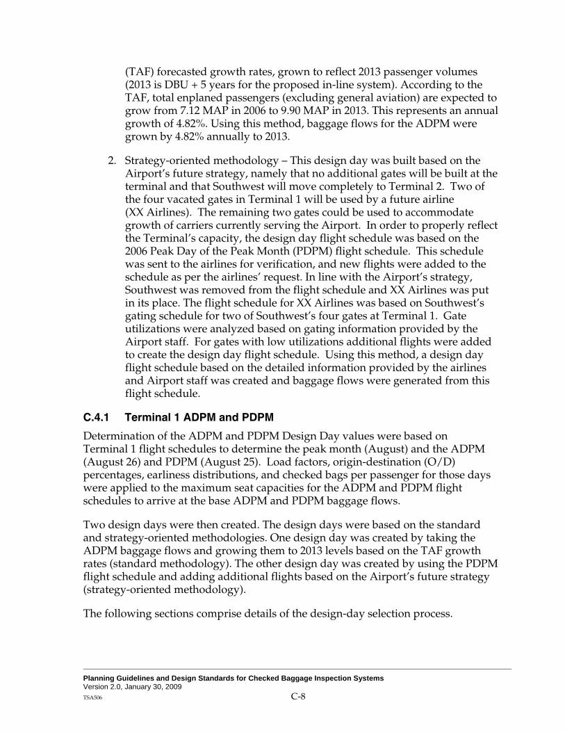
Planning Guidelines and Design Standards for Checked Baggage Inspection Systems Version 2.0, January 30, 2009 TSA506 C-8
(TAF) forecasted growth rates, grown to reflect 2013 passenger volumes (2013 is DBU + 5 years for the proposed in-line system). According to the TAF, total enplaned passengers (excluding general aviation) are expected to grow from 7.12 MAP in 2006 to 9.90 MAP in 2013. This represents an annual growth of 4.82%. Using this method, baggage flows for the ADPM were grown by 4.82% annually to 2013.
2. Strategy-oriented methodology – This design day was built based on the Airport’s future strategy, namely that no additional gates will be built at the terminal and that Southwest will move completely to Terminal 2. Two of the four vacated gates in Terminal 1 will be used by a future airline (XX Airlines). The remaining two gates could be used to accommodate growth of carriers currently serving the Airport. In order to properly reflect the Terminal’s capacity, the design day flight schedule was based on the 2006 Peak Day of the Peak Month (PDPM) flight schedule. This schedule was sent to the airlines for verification, and new flights were added to the schedule as per the airlines’ request. In line with the Airport’s strategy, Southwest was removed from the flight schedule and XX Airlines was put in its place. The flight schedule for XX Airlines was based on Southwest’s gating schedule for two of Southwest’s four gates at Terminal 1. Gate utilizations were analyzed based on gating information provided by the Airport staff. For gates with low utilizations additional flights were added to create the design day flight schedule. Using this method, a design day flight schedule based on the detailed information provided by the airlines and Airport staff was created and baggage flows were generated from this flight schedule.
C.4.1 Terminal 1 ADPM and PDPM
Determination of the ADPM and PDPM Design Day values were based on Terminal 1 flight schedules to determine the peak month (August) and the ADPM (August 26) and PDPM (August 25). Load factors, origin-destination (O/D) percentages, earliness distributions, and checked bags per passenger for those days were applied to the maximum seat capacities for the ADPM and PDPM flight schedules to arrive at the base ADPM and PDPM baggage flows.
Two design days were then created. The design days were based on the standard and strategy-oriented methodologies. One design day was created by taking the ADPM baggage flows and growing them to 2013 levels based on the TAF growth rates (standard methodology). The other design day was created by using the PDPM flight schedule and adding additional flights based on the Airport’s future strategy (strategy-oriented methodology).
The following sections comprise details of the design-day selection process.

Planning Guidelines and Design Standards for Checked Baggage Inspection Systems Version 2.0, January 30, 2009 TSA506 C-9
C.4.1.1 Peak Month
Table C-2 shows the monthly totals and daily averages for all flights in Terminal 1 used to identify August as the peak month.
Table C-2
TERMINAL 1 PEAK MONTH Available Seats 2007
Monthly seats
Average daily seats
JAN 279,034 9,001 FEB 254,786 9,100 MAR 286,400 9,239 APR 271,707 9,057 MAY 309,719 9,991 JUN 320,829 10,694 JUL 324,051 10,802 AUG 335,573 10,825 SEP 293,789 9,793 OCT 299,965 9,676 NOV 279,911 9,330 DEC 288,890 9,319
C.4.1.2 Terminal 1 ADPM and PDPM
The ADPM and PDPM were determined by analysis of the Terminal 1 daily seat calculated from the OAG flight schedules for the peak month (August 2006). The day which is closest to the peak month’s average daily load determines the ADPM. The day which is closest to the peak month’s daily peak determines the PDPM. Tables C-3 and C-4 show the daily seat totals, their variance from the monthly average and the ADPM and PDPM respectively for Terminal 1. The results of this analysis concluded that the ADPM was August 26 and the PDPM was August 25.
Table C-3 shows the total number of daily departing seats for all domestic Terminal 1 flights (excluding Southwest Airlines) obtained from the Official Airline Guide (OAG). The ADPM is identified as August 26 and the PDPM as August 25.
The ADPM flight schedule is provided in Table C-4. This is the flight schedule that is used in the standard methodology.

Planning Guidelines and Design Standards for Checked Baggage Inspection Systems Version 2.0, January 30, 2009 TSA506 C-10
Table C-3
AVERAGE DAY AND PEAK DAY OF AUGUST 2006 Daily Available Seating
Month: August 2006 Average Day Seats: 10,387
Day Available
Seats Variance from
Average
1 10,368 -19 2 10,368 -19 3 10,368 -19 4 10,492 105 5 10,388 1 6 10,244 -143 7 10,492 105 8 10,368 -19 9 10,368 -19
10 10,368 -19 11 10,492 105 12 10,388 1 13 10,244 -143 14 10,492 105 15 10,368 -19 16 10,368 -19 17 10,368 -19 18 10,492 105 19 10,388 1 20 10,244 -143 21 10,492 105 22 10,368 -19 23 10,368 -19 24 10,368 -19 25 (a) 10,492 105 26 (b) 10,388 1 27 10,244 -143 28 10,492 105 29 10,368 -19 30 10,368 -19 31 10,368 -19
(a) August 25 is the PDPM. (b) August 26 is the ADPM.

Planning Guidelines and Design Standards for Checked Baggage Inspection Systems Version 2.0, January 30, 2009 TSA506 C-11
Table C-4
OAKLAND TERMINAL 1 ADPM SCHEDULE
Published Carrier Operator
Flight Number
Departure Time Destination
Aircraft Type
Seats Config
AA AA 1008 6:26 DFW 'M80 136 AA AA 1612 8:09 DFW 'M80 136 AA AA 1092 12:43 DFW 'M80 136 AA AA 2256 15:06 DFW 'M80 136 AQ AQ 473 8:00 OGG '73W 124 AQ AQ 441 9:00 HNL '73W 124 AS AS 372 6:40 SNA '734 144 AS AS 355 9:05 SEA '734 144 AS AS 340 12:17 SNA '734 144 AS AS 346 13:40 SNA '734 144 AS AS 365 16:17 PDX '734 144 AS AS 541 17:10 SEA '734 144 AS AS 446 17:20 SNA '734 144 AS AS 459 20:15 SEA '734 144 AS AS 321 21:14 PDX '734 144 AS AS 351 6:00 SEA '739 172 AS AS 343 7:55 SEA '739 172 AS AS 573 10:01 SEA '739 172 AS AS 85 15:33 SEA '739 172 AS AS 378 18:55 SNA '73G 124 AS AS 579 7:20 PDX 'M80 140 AS AS 357 12:24 SEA 'M80 140 AS QX 2468 9:10 PDX 'CR7 70 AS QX 2534 19:10 PDX 'CR7 70 B6 B6 241 6:30 LGB '320 156 B6 B6 94 7:10 JFK '320 156 B6 B6 474 7:40 BOS '320 156 B6 B6 100 8:50 JFK '320 156 B6 B6 312 9:20 IAD '320 156 B6 B6 472 10:05 BOS '320 156 B6 B6 96 11:05 JFK '320 156 B6 B6 302 12:05 IAD '320 156 B6 B6 102 13:30 JFK '320 156 B6 B6 247 13:30 LGB '320 156 B6 B6 82 15:30 JFK '320 156 B6 B6 253 17:25 LGB '320 156 B6 B6 317 19:20 LGB '320 156 B6 B6 249 20:30 LGB '320 156 B6 B6 110 21:35 JFK '320 156 B6 B6 476 22:35 BOS '320 156 B6 B6 318 22:45 IAD '320 156 B6 B6 270 23:30 FLL '320 156

Planning Guidelines and Design Standards for Checked Baggage Inspection Systems Version 2.0, January 30, 2009 TSA506 C-12
Table C-4 (page 2 of 2) OAKLAND TERMINAL 1 ADPM SCHEDULE
Published Carrier Operator
Flight Number
Departure Time Destination
Aircraft Type
Seats Config
CO CO 284 0:20 IAH '733 124 CO CO 758 6:30 IAH '738 155 CO CO 231 12:14 IAH '739 167 DL DL 800 7:10 ATL '738 150 DL DL 494 12:05 ATL '738 150 DL DL 709 22:30 ATL '738 150 DL DL 715 13:20 SLC 'M90 150 DL OO 3796 6:15 SLC 'CRJ 50 DL OO 3957 9:41 SLC 'CRJ 50 DL OO 3998 16:02 SLC 'CRJ 50 DL OO 3928 18:30 SLC 'CRJ 50 HP HP 855 9:00 PHX '319 124 HP HP 567 6:00 PHX '320 150 HP HP 721 13:46 LAS '320 150 HP HP 191 15:40 PHX '320 150 HP HP 611 20:20 LAS '320 150 HP HP 753 12:29 PHX '733 134 HP YV 6617 9:25 PHX 'CR9 80 HP YV 6557 18:22 PHX 'CR9 80 TZ TZ 4627 9:35 OGG '73H 175 TZ TZ 4625 10:55 HNL '73H 175 TZ TZ 4517 17:20 HNL '73H 175 TZ TZ 4523 19:35 ITO '73H 175 UA A296 6515 12:37 LAX 'CRJ 49 UA A296 6505 16:34 LAX 'CRJ 49 UA A296 6507 17:35 LAX 'CRJ 49 UA A296 6501 19:56 LAX 'CRJ 49 UA UA 1193 6:30 LAX '319 120 UA UA 1230 13:50 ORD '319 120 UA UA 388 22:55 IAD '319 120 UA UA 644 23:00 ORD '319 120 UA UA 1122 6:00 DEN '320 138 UA UA 242 6:20 ORD '320 138 UA UA 386 8:10 DEN '320 138 UA UA 808 15:34 DEN '733 120 UA UA 364 11:05 DEN '735 116 UA UA 738 14:00 DEN '735 116 UA UA 328 16:45 DEN '735 116

Planning Guidelines and Design Standards for Checked Baggage Inspection Systems Version 2.0, January 30, 2009 TSA506 C-13
The PDPM flight schedule is provided in Table C-5 below. Additional flagged flights have been added to the PDPM based on the Airport’s future strategy for Terminal 1. Specifically, flights were added based upon feedback from the airlines regarding their future flight strategies as well as flights for XX Airlines, the new airline that will use two of Southwest Airline’s 4 vacated Terminal 1 gates.
Table C-5
OAKLAND TERMINAL 1 PDPM SCHEDULE
Published Carrier Operator
Flight Number
Departure Time Destination
Aircraft Type
Seats Config
Added to
PDPM
AA AA 1008 6:26 DFW M80 136 AA AA 1612 8:09 DFW M80 136 AA AA 9992 10:00 DFW M80 136 * AA AA 1092 12:43 DFW M80 136 AA AA 2256 15:06 DFW M80 136 AA AA 9993 17:00 DFW M80 136 * AQ AQ 473 8:00 OGG 73W 124 AQ AQ 441 9:00 HNL 73W 124 AQ AQ 477 10:40 KOA 73W 124 AS AS 351 6:00 SEA 739 172 AS AS 372 6:40 SNA 734 144 AS AS 579 7:20 PDX M80 140 AS AS 343 7:55 SEA 739 172 AS QX 2468 9:00 PDX CR7 70 AS AS 355 9:05 SEA 734 144 AS AS 573 10:01 SEA 739 172 AS AS 340 12:17 SNA 734 144 AS AS 357 12:24 SEA M80 140 AS AS 346 13:40 SNA 734 144 AS AS 9991 14:00 PDX 734 144 * AS AS 85 15:33 SEA 739 172 AS QX 2409 16:10 SUN DH4 74 AS AS 365 16:17 PDX 734 144 AS AS 541 17:10 SEA 734 144 AS AS 446 17:20 SNA 734 144 AS AS 378 18:55 SNA 73G 124 AS QX 2534 19:10 PDX CR7 70 AS AS 459 20:15 SEA 734 144 AS AS 9990 20:30 SNA 734 144 * AS AS 321 21:14 PDX 734 144 B6 B6 241 6:30 LGB 320 156 B6 B6 94 7:10 JFK 320 156 B6 B6 474 7:40 BOS 320 156 B6 B6 100 8:50 JFK 320 156 B6 B6 312 9:20 IAD 320 156 B6 B6 472 10:05 BOS 320 156 B6 B6 96 11:05 JFK 320 156

Planning Guidelines and Design Standards for Checked Baggage Inspection Systems Version 2.0, January 30, 2009 TSA506 C-14
Table C-5 (page 2 of 3) OAKLAND TERMINAL 1 PDPM SCHEDULE
Published Carrier Operator
Flight Number
Departure Time Destination
Aircraft Type
Seats Config
Added to
PDPM
B6 B6 302 12:05 IAD 320 156 B6 B6 102 13:30 JFK 320 156 B6 B6 247 13:30 LGB 320 156 B6 B6 82 15:30 JFK 320 156 B6 B6 253 17:25 LGB 320 156 B6 B6 317 19:20 LGB 320 156 B6 B6 249 20:30 LGB 320 156 B6 B6 110 21:35 JFK 320 156 B6 B6 476 22:35 BOS 320 156 B6 B6 318 22:45 IAD 320 156 B6 B6 270 23:30 FLL 320 156 CO CO 284 0:20 IAH CO 733 124 CO CO 284 0:20 IAH CO 733 124 CO CO 758 6:30 IAH CO 738 155 CO CO 231 12:14 IAH CO 739 167 DL OO 3796 6:15 SLC CRJ 50 DL DL 800 7:10 ATL 738 150 DL OO 3957 9:41 SLC CRJ 50 DL DL 9994 10:30 ATL 738 150 * DL DL 494 12:05 ATL 738 150 DL DL 1743 13:20 SLC M90 150 DL DL 9995 16:00 ATL 738 150 * DL OO 3998 16:02 SLC CRJ 50 DL OO 3928 18:30 SLC CRJ 50 DL DL 709 22:30 ATL 738 150 HP HP 567 6:00 PHX 320 150 HP HP 381 7:40 SJD 733 134 HP HP 855 9:00 PHX 319 124 HP YV 6617 9:25 PHX CR9 80 HP HP 753 12:29 PHX 733 134 HP HP 721 13:46 LAS 320 150 HP HP 626 15:40 PHX 733 134 HP YV 6557 18:22 PHX CR9 80 HP HP 539 20:20 LAS 319 124 TZ TZ 4627 9:35 OGG 73H 175 TZ TZ 4625 10:55 HNL 73H 175 TZ TZ 4517 17:20 HNL 73H 175 TZ TZ 4523 19:35 ITO 73H 175 UA UA 1122 6:00 DEN UA 320 138 UA UA 242 6:20 ORD UA 320 138 UA UA 281 7:30 IAD UA 320 138 UA UA 386 8:10 DEN UA 320 138 UA UA 9980 9:40 LAX UA 733 137 * UA UA 9981 12:00 ORD UA 73G 137 *

Planning Guidelines and Design Standards for Checked Baggage Inspection Systems Version 2.0, January 30, 2009 TSA506 C-15
Table C-5 (page 3 of 3) OAKLAND TERMINAL 1 PDPM SCHEDULE
Published Carrier Operator
Flight Number
Departure Time Destination
Aircraft Type
Seats Config
Added to
PDPM
UA A296 6515 12:37 LAX CRJ 49 UA UA 1230 13:50 ORD UA 319 120 UA UA 9982 14:50 LAX UA 73G 137 * UA UA 808 15:34 DEN UA 733 120 UA UA 9983 16:20 ORD UA 733 137 * UA A296 6505 16:34 LAX CRJ 49 UA A296 6507 17:35 LAX CRJ 49 UA A296 6501 19:56 LAX CRJ 49 UA UA 9996 22:00 ORD UA 320 138 * UA UA 388 22:55 IAD UA 319 120 * XX XX 398 6:05 SAN 73G 137 * XX XX 1380 6:30 LAX 733 137 * XX XX 825 6:55 ONT 73G 137 * XX XX 2432 7:25 BUR 733 137 * XX XX 1233 7:40 SAN 733 137 * XX XX 1474 7:40 RNO 733 137 * XX XX 1215 7:50 SEA 73G 137 * XX XX 997 9:00 MDW 73G 137 * XX XX 1726 9:35 BUR 733 137 * XX XX 493 11:00 LAX 733 137 * XX XX 622 11:10 BOI 733 137 * XX XX 1409 11:35 LAS 733 137 * XX XX 1041 11:40 BUR 73G 137 * XX XX 1284 13:35 BUR 733 137 * XX XX 530 13:55 LAS 733 137 * XX XX 1790 14:40 ONT 73G 137 * XX XX 1385 16:00 LAX 733 137 * XX XX 907 17:30 LAX 73G 137 * XX XX 1853 17:35 SNA 73G 137 * XX XX 1055 18:10 ONT 733 137 * XX XX 1735 18:15 BUR 733 137 * XX XX 1381 19:20 SLC 733 137 * XX XX 1834 19:55 SAN 73G 137 * XX XX 1795 20:05 ONT 73G 137 * XX XX 1776 22:00 LAX 73G 137 *
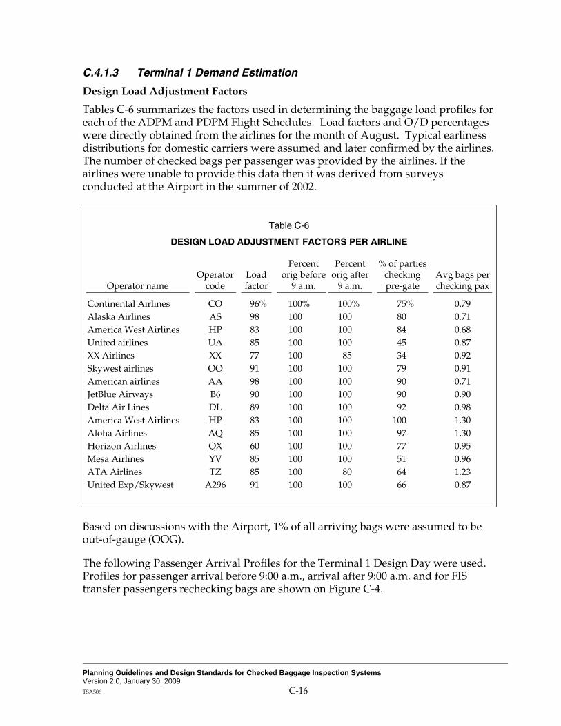
Planning Guidelines and Design Standards for Checked Baggage Inspection Systems Version 2.0, January 30, 2009 TSA506 C-16
C.4.1.3 Terminal 1 Demand Estimation
Design Load Adjustment Factors
Tables C-6 summarizes the factors used in determining the baggage load profiles for each of the ADPM and PDPM Flight Schedules. Load factors and O/D percentages were directly obtained from the airlines for the month of August. Typical earliness distributions for domestic carriers were assumed and later confirmed by the airlines. The number of checked bags per passenger was provided by the airlines. If the airlines were unable to provide this data then it was derived from surveys conducted at the Airport in the summer of 2002.
Table C-6
DESIGN LOAD ADJUSTMENT FACTORS PER AIRLINE
Operator name Operator
code Load factor
Percent orig before
9 a.m.
Percent orig after
9 a.m.
% of parties checking pre-gate
Avg bags per checking pax
Continental Airlines CO 96% 100% 100% 75% 0.79 Alaska Airlines AS 98 100 100 80 0.71 America West Airlines HP 83 100 100 84 0.68 United airlines UA 85 100 100 45 0.87 XX Airlines XX 77 100 85 34 0.92 Skywest airlines OO 91 100 100 79 0.91 American airlines AA 98 100 100 90 0.71 JetBlue Airways B6 90 100 100 90 0.90 Delta Air Lines DL 89 100 100 92 0.98 America West Airlines HP 83 100 100 100 1.30 Aloha Airlines AQ 85 100 100 97 1.30 Horizon Airlines QX 60 100 100 77 0.95 Mesa Airlines YV 85 100 100 51 0.96 ATA Airlines TZ 85 100 80 64 1.23 United Exp/Skywest A296 91 100 100 66 0.87
Based on discussions with the Airport, 1% of all arriving bags were assumed to be out-of-gauge (OOG).
The following Passenger Arrival Profiles for the Terminal 1 Design Day were used. Profiles for passenger arrival before 9:00 a.m., arrival after 9:00 a.m. and for FIS transfer passengers rechecking bags are shown on Figure C-4.
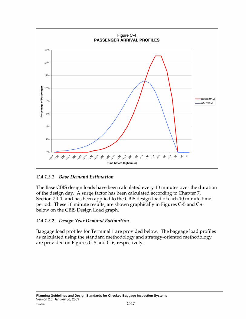
Planning Guidelines and Design Standards for Checked Baggage Inspection Systems Version 2.0, January 30, 2009 TSA506 C-17
Figure C-4 PASSENGER ARRIVAL PROFILES
0%
2%
4%
6%
8%
10%
12%
14%
16%
-240 -230 -220 -210 -200 -190 -180 -170 -160 -150 -140 -130 -120 -110 -100 -90 -80 -70 -60 -50 -40 -30 -20 -10 0
Time before flight (min)
Perc
enta
ge o
f Pas
seng
ers
Before 9AMAfter 9AM
C.4.1.3.1 Base Demand Estimation
The Base CBIS design loads have been calculated every 10 minutes over the duration of the design day. A surge factor has been calculated according to Chapter 7, Section 7.1.1, and has been applied to the CBIS design load of each 10 minute time period. These 10 minute results, are shown graphically in Figures C-5 and C-6 below on the CBIS Design Load graph.
C.4.1.3.2 Design Year Demand Estimation
Baggage load profiles for Terminal 1 are provided below. The baggage load profiles as calculated using the standard methodology and strategy-oriented methodology are provided on Figures C-5 and C-6, respectively.

Planning Guidelines and Design Standards for Checked Baggage Inspection Systems Version 2.0, January 30, 2009 TSA506 C-18
Figure C-5 STANDARD METHODOLOGY DESIGN LOAD PROFILE
-
200
400
600
800
1,000
1,200
0:00 2:00 4:00 6:00 8:00 10:00 12:00 14:00 16:00 18:00 20:00 22:00
Time of Day (hh:mm)
Hour
ly B
ag F
low
(bph
)
2006 Unsurged 2006 Surged 2013 Unsurged 2013 Surged
Figure C-6 STRATEGY ORIENTATED METHODOLOGY DESIGN LOAD PROFILE
-
200
400
600
800
1,000
1,200
0:00 2:00 4:00 6:00 8:00 10:00 12:00 14:00 16:00 18:00 20:00 22:00 0:00
Time of Day (hh:mm)
Hou
rly B
ag F
low
(bph
)
PDPM Unsurged PDPM Surged Design Day Unsurged Design Day Surged
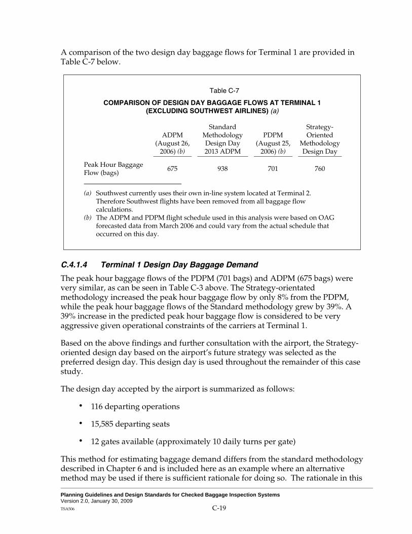
Planning Guidelines and Design Standards for Checked Baggage Inspection Systems Version 2.0, January 30, 2009 TSA506 C-19
A comparison of the two design day baggage flows for Terminal 1 are provided in Table C-7 below.
Table C-7
COMPARISON OF DESIGN DAY BAGGAGE FLOWS AT TERMINAL 1 (EXCLUDING SOUTHWEST AIRLINES) (a)
ADPM (August 26,
2006) (b)
Standard Methodology Design Day 2013 ADPM
PDPM (August 25,
2006) (b)
Strategy-Oriented
Methodology Design Day
Peak Hour Baggage Flow (bags) 675 938 701 760
(a) Southwest currently uses their own in-line system located at Terminal 2. Therefore Southwest flights have been removed from all baggage flow calculations.
(b) The ADPM and PDPM flight schedule used in this analysis were based on OAG forecasted data from March 2006 and could vary from the actual schedule that occurred on this day.
C.4.1.4 Terminal 1 Design Day Baggage Demand
The peak hour baggage flows of the PDPM (701 bags) and ADPM (675 bags) were very similar, as can be seen in Table C-3 above. The Strategy-orientated methodology increased the peak hour baggage flow by only 8% from the PDPM, while the peak hour baggage flows of the Standard methodology grew by 39%. A 39% increase in the predicted peak hour baggage flow is considered to be very aggressive given operational constraints of the carriers at Terminal 1.
Based on the above findings and further consultation with the airport, the Strategy-oriented design day based on the airport’s future strategy was selected as the preferred design day. This design day is used throughout the remainder of this case study.
The design day accepted by the airport is summarized as follows:
116 departing operations
15,585 departing seats
12 gates available (approximately 10 daily turns per gate)
This method for estimating baggage demand differs from the standard methodology described in Chapter 6 and is included here as an example where an alternative method may be used if there is sufficient rationale for doing so. The rationale in this

Planning Guidelines and Design Standards for Checked Baggage Inspection Systems Version 2.0, January 30, 2009 TSA506 C-20
case is based on two key observations. The first observation is that the high gate utilization indicates that the terminal is currently operating at or near maximum capacity. The second observation is that site constraints limit future gate expansion to 2 gates. The schedule that was developed represents a reasonable estimate of the maximum demand that the terminal could ever accommodate. When using a demand estimation methodology different from that described in PGDS Chapter 6, justification for doing so must be provided to the TSA. TSA must review and approve the method and results before proceeding with design.
C.5 QUANTITATIVE ASSESSMENT
C.5.1 Base Demand Estimation
Existing checked baggage screening flows have to be estimated for each of the seven F3 screening zones. The F3 screening zones and CBRA were the same for feasible Alternatives 1 and 2. Alternative 3 combines ticket counter groups into common CBRA’s. However, each ticket counter group still feeds it’s own EDS scanner. Therefore the base demand and Design Day Peak Hour Surged Baggage Volume calculations to determine the required number of EDS machines for each of the F3 zones (ticket counter groups) below is applicable to each of the feasible alternatives.
C.5.1.1 List of Airlines
Table C-8 lists Terminal 1 airlines by screening zone. The F1 and F2 zone groupings have been removed, since all of the F1 and F2 alternatives were deemed spatially infeasible during the initial pass of alternatives in Section 3.4 above.

Planning Guidelines and Design Standards for Checked Baggage Inspection Systems Version 2.0, January 30, 2009 TSA506 C-21
Table C-8
LIST OF AIRLINES BY SCREENING ZONE Terminal 1
Zone Airlines
F31 B6 F32 AQ, CO F33 AA F34 HP, YV, US F35 AS, QX F36 DL, OO, TZ F37 UA, A296, XX (a)
Legend: AQ - Aloha Airlines CO - Continental Airlines AA - American Airlines HP - America West YV - Mesa Airlines US - US Air AS - Alaska Airlines QX - Horizon Airlines DL - Delta Airlines OO - Sky West TZ - ATA UA - United Airlines A296 - United Express B6 – JetBlue
(a) Assumed new entrant using currently occupied gates that will be availability after completion of expansion of Terminal 2.
The Design Day flight schedules for each screening zone were created using the strategy-oriented methodology described in Section 4.0 above. These flight schedules identify the maximum number of aircraft seats available and are the basis of the BHS design load profile. Flight schedules for each of the screening zones have been presented earlier in Tables C-4 and C-5.
C.5.1.2 Base Year Demand Estimation
As described in PGDS Chapter 6, a separate analysis should be conducted to determine the PDPM for each F3 screening zone, based on flight schedules obtained from the OAG. Since the strategy-oriented methodology was used, and flights were added to the schedule based on feedback from the airlines, the design day schedule had higher seat levels for each F3 zone than any of the other days in the peak month (August). Table C-9 below lists the Peak Month and Peak Day for each zone.

Planning Guidelines and Design Standards for Checked Baggage Inspection Systems Version 2.0, January 30, 2009 TSA506 C-22
Table C-9
F3 SCREENING ZONE PEAK MONTH & PEAK DAY
Zone Airlines Peak
Month Peak Day
F31 B6 August 25 F32 AQ, CO August 25 F33 AA August 25 F34 HP, YV, US August 25 F35 AS, QX August 25 F36 DL, OO, TZ August 25 F37 UA, A296, XX August 25
The Terminal 1 design load adjustment factors and rates identified in Table C-6 and the Passenger Arrival Profiles identified on Figure C-4 above were applied to the maximum seat capacity identified in each of the PDPM flight schedules for each of the F3 screening zones.
Figures C-7 to C-13 below are the CBIS Design Load Graphs for the F31 to F37 screening zones. The Base Year CBIS design loads have been calculated every 10 minutes over the duration of the design day. A surge factor has been calculated according to PGDS 7.1.1, and has been applied to the CBIS design load of each 10 minute time period. These 10 minute results are shown graphically on Figures C-7 to C-13 on the CBIS design load graphs.
C.5.2 Design Day Demand Estimation
The surged design load for each F3 screening zone is provided below based on the strategy-oriented methodology. These 10 minute baggage flow results are shown graphically in Figures C-7 to C-13 on the CBIS design load graphs.

Planning Guidelines and Design Standards for Checked Baggage Inspection Systems Version 2.0, January 30, 2009 TSA506 C-23
Figure C-7 STRATEGY ORIENTATED METHODOLOGY DESIGN LOAD PROFILE
F3-1 Zone Level
0
50
100
150
200
250
300
350
0:00 2:00 4:00 6:00 8:00 10:00 12:00 14:00 16:00 18:00 20:00 22:00 0:00
Time of Day (hh:mm)
Hou
rly B
ag F
low
(bph
)
PDPM Unsurged PDPM Surged Design Day Unsurged Design Day Surged
Figure C-8 STRATEGY ORIENTATED METHODOLOGY DESIGN LOAD PROFILE
F3-2 Zone Level
0
50
100
150
200
250
300
0:00 2:00 4:00 6:00 8:00 10:00 12:00 14:00 16:00 18:00 20:00 22:00 0:00
Time of Day (hh:mm)
Hou
rly B
ag F
low
(bph
)
PDPM Unsurged PDPM Surged Design Day Unsurged Design Day Surged

Planning Guidelines and Design Standards for Checked Baggage Inspection Systems Version 2.0, January 30, 2009 TSA506 C-24
Figure C-9 STRATEGY ORIENTATED METHODOLOGY DESIGN LOAD PROFILE
F3-3 Zone Level
0
20
40
60
80
100
120
140
0:00 2:00 4:00 6:00 8:00 10:00 12:00 14:00 16:00 18:00 20:00 22:00 0:00
Time of Day (hh:mm)
Hou
rly B
ag F
low
(bph
)
PDPM Unsurged PDPM Surged Design Day Unsurged Design Day Surged
Figure C-10 STRATEGY ORIENTATED METHODOLOGY DESIGN LOAD PROFILE
F3-4 Zone Level
0
20
40
60
80
100
120
140
0:00 2:00 4:00 6:00 8:00 10:00 12:00 14:00 16:00 18:00 20:00 22:00 0:00
Time of Day (hh:mm)
Hou
rly B
ag F
low
(bph
)
PDPM Unsurged PDPM Surged Design Day Unsurged Design Day Surged

Planning Guidelines and Design Standards for Checked Baggage Inspection Systems Version 2.0, January 30, 2009 TSA506 C-25
Figure C-11 STRATEGY ORIENTATED METHODOLOGY DESIGN LOAD PROFILE
F3-5 Zone Level
0
50
100
150
200
250
0:00 2:00 4:00 6:00 8:00 10:00 12:00 14:00 16:00 18:00 20:00 22:00 0:00
Time of Day (hh:mm)
Hou
rly B
ag F
low
(bph
)
PDPM Unsurged PDPM Surged Design Day Unsurged Design Day Surged
Figure C-12 STRATEGY ORIENTATED METHODOLOGY DESIGN LOAD PROFILE
F3-6 Zone Level
0
50
100
150
200
250
0:00 2:00 4:00 6:00 8:00 10:00 12:00 14:00 16:00 18:00 20:00 22:00 0:00
Time of Day (hh:mm)
Hou
rly B
ag F
low
(bph
)
PDPM Unsurged PDPM Surged Design Day Unsurged Design Day Surged

Planning Guidelines and Design Standards for Checked Baggage Inspection Systems Version 2.0, January 30, 2009 TSA506 C-26
Figure C-13 STRATEGY ORIENTATED METHODOLOGY DESIGN LOAD PROFILE
F3-7 Zone Level
0
20
40
60
80
100
120
140
160
180
0:00 2:00 4:00 6:00 8:00 10:00 12:00 14:00 16:00 18:00 20:00 22:00 0:00
Time of Day (hh:mm)
Hou
rly B
ag F
low
(bph
)
PDPM Unsurged PDPM Surged Design Day Unsurged Design Day Surged
Table C-10 summarizes the PDPM (2008), PDPM Surged, and Design Day and Design Day Surged Peak Hour Baggage Volumes for each of the F3 screening zones.
Table C-10
F3 SCREENING ZONE PEAK HOUR BAGGAGE VOLUMES
Peak Hour Baggage Volume Design Day Zone Airlines PDPM PDPM Surged Design Day Surged
F31 B6 236 311 236 311 F32 AQ, CO 188 256 188 256 F33 AA 80 123 84 129 F34 HP, YV, US 65 105 161 224 F35 AS, QX 164 227 166 229 F36 DL, OO, TZ 114 166 154 215 F37 UA, A296, XX 113 165 186 253
Using the Surged Peak Hour Design Day Baggage Volume, EDS, OSR, and ETD Equipment Requirements can be calculated for each of the three feasible alternatives based on the high-level methodology described in PGDS Chapter 6.

Planning Guidelines and Design Standards for Checked Baggage Inspection Systems Version 2.0, January 30, 2009 TSA506 C-27
C.5.3 Feasible Alternative 1 – CT-80 EDS Machines
This alternative is a conceptual layout for the F3 Zone grouping of Terminal 1. Seventeen Reveal CT-80 EDS machines are placed directly behind the ticket counters. The ticket counters are divided into 7 ticket counter groups (F3 Zone grouping). Each group is served by 1, 2, or 3 EDS machines and 1 CBRA, where combined OSR and ETD screening functions are performed. The machines are located directly behind the ticket agents and are parallel to the ticket counters. Each grouping of machines has a single conveyor leading to the make-up area and CBRA. The OSR and ETD screening functions are combined and performed in the CBRAs. The differences between dedicated and combined OSR functionality would be investigated further if Alternative 1 was chosen as a preferred alternative; however, given the highly decentralized nature of this alternative, combined OSR/ETD is likely to be the most cost-effective approach. A conceptual drawing of Alternative 1 is provided on Figure C-14.
Figure C-14 TERMINAL 1 ALTERNATIVE 1 CONCEPTUAL DRAWING
C.5.3.1 EDS Screening Equipment
Feasible Alternative 1 is based on the use of Reveal CT-80 EDS machines. As reported in PGDS Chapter 5, the use of CT-80 EDS machines in a mini in-line system yield a throughput of 120 bags per hour. The peak-hour surged baggage volume is divided by the assumed EDS equipment throughput, yielding the quantity of required EDS machines. Always round up to the next whole EDS machine without considering redundancy.
As discussed in previous paragraphs, activity at Terminal 1 is constrained by the number of gates, thus it is unlikely that additional growth will occur at this terminal beyond the design year. For this reason, the system does not need additional
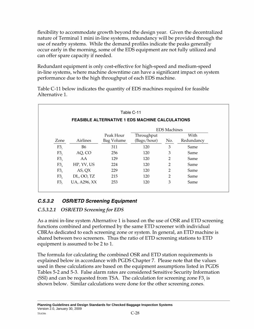
Planning Guidelines and Design Standards for Checked Baggage Inspection Systems Version 2.0, January 30, 2009 TSA506 C-28
flexibility to accommodate growth beyond the design year. Given the decentralized nature of Terminal 1 mini in-line systems, redundancy will be provided through the use of nearby systems. While the demand profiles indicate the peaks generally occur early in the morning, some of the EDS equipment are not fully utilized and can offer spare capacity if needed.
Redundant equipment is only cost-effective for high-speed and medium-speed in-line systems, where machine downtime can have a significant impact on system performance due to the high throughput of each EDS machine.
Table C-11 below indicates the quantity of EDS machines required for feasible Alternative 1.
Table C-11
FEASIBLE ALTERNATIVE 1 EDS MACHINE CALCULATIONS
EDS Machines
Zone Airlines Peak Hour
Bag Volume Throughput (Bags/hour) No.
With Redundancy
F31 B6 311 120 3 Same F32 AQ, CO 256 120 3 Same F33 AA 129 120 2 Same F34 HP, YV, US 224 120 2 Same F35 AS, QX 229 120 2 Same F36 DL, OO, TZ 215 120 2 Same F37 UA, A296, XX 253 120 3 Same
C.5.3.2 OSR/ETD Screening Equipment
C.5.3.2.1 OSR/ETD Screening for EDS
As a mini in-line system Alternative 1 is based on the use of OSR and ETD screening functions combined and performed by the same ETD screener with individual CBRAs dedicated to each screening zone or system. In general, an ETD machine is shared between two screeners. Thus the ratio of ETD screening stations to ETD equipment is assumed to be 2 to 1.
The formula for calculating the combined OSR and ETD station requirements is explained below in accordance with PGDS Chapter 7. Please note that the values used in these calculations are based on the equipment assumptions listed in PGDS Tables 5-2 and 5-3. False alarm rates are considered Sensitive Security Information (SSI) and can be requested from TSA. The calculation for screening zone F31 is shown below. Similar calculations were done for the other screening zones.

Planning Guidelines and Design Standards for Checked Baggage Inspection Systems Version 2.0, January 30, 2009 TSA506 C-29
Note: All EDS false alarm rates and OSR clear rate are notional and are used for this example only. Please contact TSA to obtain actual false alarm rates and OSR clear rates.
The number of combined OSR and ETD screening stations required for zone F31:
NETD Station = (Sum of ThroughputEDS * FAEDS)/(ThroughputOSR/ETD Screener)
= (360 bph * 19.5%)/34.5 bph
= 2.03 • 3 (rounded up)
NETD Machines = (NETD Screeners/2) rounded up to the next ETD
= (3/2)
= 2 ETD Machines
Table C-12 below indicates the quantity of combined OSR/ETD stations and ETD machines required for Alternative 1.
Table C-12
FEASIBLE ALTERNATIVE 1 OSR/ETD CALCULATIONS
Peak EDS Machines No. of
Combined No. of
Zone Airlines Hour Bag Volume
Throughput (Bags/hour) No.
With Redundancy
OSR/ETD Stations
ETD Machines
F31 B6 311 120 3 Same 3 2 F32 AQ, CO 256 120 3 Same 3 2 F33 AA 129 120 2 Same 2 1 F34 HP, YV, US 224 120 2 Same 2 1 F35 AS, QX 229 120 2 Same 2 1 F36 DL, OO, TZ 215 120 2 Same 2 1 F37 UA, A296, XX 253 120 3 Same 3 2
C.5.3.2.2 ETD Screening for Oversize and Out of Gauge Baggage
Based on discussions with the Airport and analysis of the CT-80 and AN KC design specifications, it was assumed that 1% of all checked baggage at Terminal 1 is either oversized or out-of-gauge (OOG). These bags would be manually taken by the ticketing agent to the opposite end of the CBIS and given to the TSA agents working at the ETD stations for directed trace screening.

Planning Guidelines and Design Standards for Checked Baggage Inspection Systems Version 2.0, January 30, 2009 TSA506 C-30
C.5.4 Feasible Alternative 2 – Analogic King Cobra EDS Machines
This alternative is a conceptual design for the F3 Zone grouping of Terminal 1. As shown on Figure C-15, 7 AN KC EDS machines are used. The ticket counters are divided into the same 7 ticket counter groups as in Alternative 1. However, each group is served by one EDS machine integrated downstream of the ticket counter take-away conveyor. This alternative was further split into two parts, Alternative 2a and Alternative 2b. Alternative 2a has combined OSR and ETD screening functions, similar to Alternative 1. Alternative 2b uses dedicated OSR screening, which would be conducted in a separate screening room. The conceptual drawings for Alternative 2a and Alternative 2b are the same, except for the remote OSR room which is already built as part of the existing in-line system in Terminal 2.
Figure C-15
TERMINAL 1 ALTERNATIVE 2A AND 2B CONCEPTUAL DIAGRAM
C.5.4.1 EDS Screening Equipment
Feasible Alternatives 2 and 3 are based on the use Analogic King Cobra (AN KC) EDS machines. Since each alternative has each ticket counter line feeding an EDS scanner, the EDS equipment requirements will be the same for both alternatives. As reported in PGDS Chapter 5, the use of AN KC EDS machines in a mini in-line system yields a throughput of 350 bags per hour per machine. The peak-hour surged baggage volume is divided by the assumed EDS equipment throughput yielding the quantity of required EDS machines. Per the PGDS, machine requirements should be rounded up to the next whole EDS machine exclusively of redundancy considerations.
As discussed in previous paragraphs, activity at Terminal 1 is constrained by the number of gates, thus it is unlikely that additional growth will occur at this terminal

Planning Guidelines and Design Standards for Checked Baggage Inspection Systems Version 2.0, January 30, 2009 TSA506 C-31
beyond the design year. For this reason, the system does not need additional flexibility to accommodate growth beyond the design year. Given the decentralized nature of Terminal 1 mini in-line systems, redundancy will be provided through the use of nearby systems. While the demand profiles indicate the peaks generally occur early in the morning, some of the EDS equipment are not fully utilized and can offer spare capacity if needed.
Redundant equipment is only cost-effective for high-speed and medium-speed in-line systems, where machine downtime can have a significant impact on system performance due to the high throughput of each EDS machine.
Table C-13 below indicates the quantity of EDS machines required for feasible Alternatives 2 and 3.
Table C-13
FEASIBLE ALTERNATIVE 2 AND 3 EDS MACHINE CALCULATIONS
Peak EDS Machines
Zone Airlines Hour Bag Volume
Throughput (Bags/hour) No.
With Redundancy
F31 B6 311 350 1 Same F32 AQ, CO 256 350 1 Same F33 AA 129 350 1 Same F34 HP, YV, US 224 350 1 Same F35 AS, QX 229 350 1 Same F36 DL, OO, TZ 215 350 1 Same F37 UA, A296, XX 253 350 1 Same
C.5.4.2 OSR and ETD Screening Equipment
C.5.4.2.1 Alternative 2a Combined OSR/ETD
As a mini in-line system Alternative 2a is based on the use of OSR and ETD screening functions combined and performed by the same ETD screener with individual CBRAs dedicated to each screening zone or system. In general, an ETD machine is shared between two screeners. Thus the ratio of ETD screening stations to ETD equipment is assumed to be 2 to 1.
The formula for calculating the combined OSR and ETD station requirements is explained below in accordance with PGDS Chapter 7. Please note that all of the values used in these calculations are based on the equipment assumptions listed in PGDS Tables 5-2 and 5-3. False alarm rates are considered Sensitive Security Information (SSI) and can be requested from TSA. The calculation for screening zone F31 is shown below. Similar calculations were done for the other screening zones.

Planning Guidelines and Design Standards for Checked Baggage Inspection Systems Version 2.0, January 30, 2009 TSA506 C-32
The number of combined OSR and ETD screening stations required for zone F31:
NETD Station = (Sum of ThroughputEDS * FAEDS)/(ThroughputOSR/ETD Screener)
= (350 bph * 15%)/45.3 bph
= 1.16 • 2 (rounded up)
NETD Machines = (NETD Screeners/2) rounded up to the next ETD
= (2/2)
= 1 ETD Machine
C.5.4.2.2 Alternative 2b Dedicated OSR Screening
As a mini in-line system Alternative 2b is based on the use of dedicated OSR and ETD screening functions performed by different screeners with individual CBRAs dedicated to each screening zone or system. In general, an ETD machine is shared between two screeners. Thus the ratio of ETD screening stations to ETD equipment is assumed to be 2 to 1.
The formula for calculating dedicated OSR and ETD station requirements is explained below in accordance with PGDS Chapter 7. Please note that the values used in these calculations are based on the equipment assumptions listed in PGDS Tables 5-2 and 5-3. False alarm rates are considered to be SSI and can be requested from TSA. The calculation for screening zone F31 is shown below. Similar calculations were done for the other screening zones.
Note: All EDS false alarm rates and OSR clear rate are notional and are used for this example only. Please contact TSA to obtain actual false alarm rates and OSR clear rates.
The number of separate OSR and ETD screening stations required:
N OSR = (Sum of ThroughputEDS* FAEDS)/(ThroughputOSR)
= (350 bph * 15%)/(180 bph)
= 0.29 • 1
NETD Station = (Sum of ThroughputEDS * FAEDS * (1-CROSR))/(ThroughputETD Screener)
= (350 bph* 15% *(40%))/24.2 bph
= 0.87 • 1
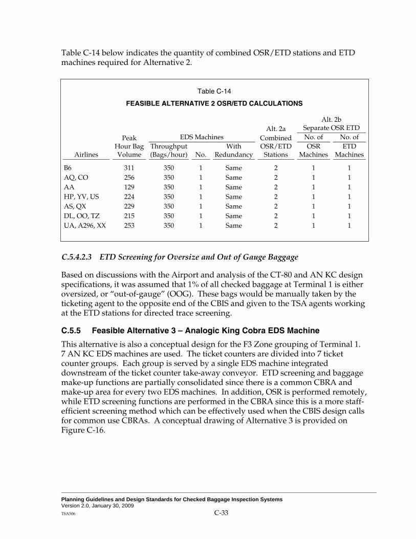
Planning Guidelines and Design Standards for Checked Baggage Inspection Systems Version 2.0, January 30, 2009 TSA506 C-33
Table C-14 below indicates the quantity of combined OSR/ETD stations and ETD machines required for Alternative 2.
Table C-14
FEASIBLE ALTERNATIVE 2 OSR/ETD CALCULATIONS
Alt. 2a Alt. 2b
Separate OSR ETD Peak EDS Machines Combined No. of No. of
Airlines Hour Bag Volume
Throughput (Bags/hour) No.
With Redundancy
OSR/ETD Stations
OSR Machines
ETD Machines
B6 311 350 1 Same 2 1 1 AQ, CO 256 350 1 Same 2 1 1 AA 129 350 1 Same 2 1 1 HP, YV, US 224 350 1 Same 2 1 1 AS, QX 229 350 1 Same 2 1 1 DL, OO, TZ 215 350 1 Same 2 1 1 UA, A296, XX 253 350 1 Same 2 1 1
C.5.4.2.3 ETD Screening for Oversize and Out of Gauge Baggage
Based on discussions with the Airport and analysis of the CT-80 and AN KC design specifications, it was assumed that 1% of all checked baggage at Terminal 1 is either oversized, or “out-of-gauge” (OOG). These bags would be manually taken by the ticketing agent to the opposite end of the CBIS and given to the TSA agents working at the ETD stations for directed trace screening.
C.5.5 Feasible Alternative 3 – Analogic King Cobra EDS Machine
This alternative is also a conceptual design for the F3 Zone grouping of Terminal 1. 7 AN KC EDS machines are used. The ticket counters are divided into 7 ticket counter groups. Each group is served by a single EDS machine integrated downstream of the ticket counter take-away conveyor. ETD screening and baggage make-up functions are partially consolidated since there is a common CBRA and make-up area for every two EDS machines. In addition, OSR is performed remotely, while ETD screening functions are performed in the CBRA since this is a more staff-efficient screening method which can be effectively used when the CBIS design calls for common use CBRAs. A conceptual drawing of Alternative 3 is provided on Figure C-16.

Planning Guidelines and Design Standards for Checked Baggage Inspection Systems Version 2.0, January 30, 2009 TSA506 C-34
Figure C-16
TERMINAL 1 ALTERNATIVE 3 CONCEPTUAL DIAGRAM
C.5.5.1 Base Demand for Combined CBRAs
C.5.5.1.1 Surged Design Day PDPM for the Combined CBRAs
Feasible Alternative 3 combines ticket counter groups into common CBRAs for OSR & ETD screening. There are now three common CBRAs comprised of F3 screening zones, F31-3, F34-5, and F36-7. See Figure C-10 above. To make an accurate calculation of the Design Day peak baggage flow that will reach the common CBRAs, separate Base Demand and Peak Day Demand calculations need to be run based on the combined airline and flight schedules for each of the common CBRAs.
The Peak Month and the ADPM for each of the CBRA zones should be calculated if the standard methodology is used. Since the strategy-oriented methodology is used, where the design day was created based on feedback from the airlines, this will not work. However an example of the recommended layout is provided.

Planning Guidelines and Design Standards for Checked Baggage Inspection Systems Version 2.0, January 30, 2009 TSA506 C-35
Table C-15
COMBINED CBRAs PEAK MONTH AND PEAK DAY
Zone Airlines Peak
Month Peak Day
F31-3 B6, AQ, CO, AA August 25 F34-5 HP, YV, US, AS, QX August 25 F36-7 DL, OO, TZ, UA, A296, XX August 25
The Terminal 1 design load adjustment factors and rates identified in Table C-6 and the Passenger Arrival Profiles identified on Figure C-4 above were applied to the maximum seat capacity identified in each of the PDPM Flight Schedules for each of the combined CBRA zones.
C.5.5.1.2 Design Day Demand Estimation for Combined CBRA
Figures C-17 to C-19 below represent the CBIS design load graphs for the F31-3, F34-5, and F36-7 screening zones. The Base Year CBIS design loads have been calculated every 10 minutes over the duration of the design day. A surge factor has been calculated according to PGDS 7.1.1, and has been applied to the CBIS design load of each 10-minute time period. These 10 minute results are shown graphically in the following charts.
Figure C-17 STRATEGY ORIENTATED METHODOLOGY DESIGN LOAD PROFILE
F3-1 to 3 Zone Level
0
100
200
300
400
500
600
0:00 2:00 4:00 6:00 8:00 10:00 12:00 14:00 16:00 18:00 20:00 22:00 0:00
Time of Day (hh:mm)
Hou
rly B
ag F
low
(bph
)
PDPM Unsurged PDPM Surged Design Day Unsurged Design Day Surged

Planning Guidelines and Design Standards for Checked Baggage Inspection Systems Version 2.0, January 30, 2009 TSA506 C-36
Figure C-18 STRATEGY ORIENTATED METHODOLOGY DESIGN LOAD PROFILE
F3-4 to 5 Zone Level
0
50
100
150
200
250
300
350
0:00 2:00 4:00 6:00 8:00 10:00 12:00 14:00 16:00 18:00 20:00 22:00 0:00
Time of Day (hh:mm)
Hou
rly B
ag F
low
(bph
)
PDPM Unsurged PDPM Surged Design Day Unsurged Design Day Surged
Figure C-19 STRATEGY ORIENTATED METHODOLOGY DESIGN LOAD PROFILE
F3-6 to 7 Zone Level
0
50
100
150
200
250
300
0:00 2:00 4:00 6:00 8:00 10:00 12:00 14:00 16:00 18:00 20:00 22:00 0:00
Time of Day (hh:mm)
Hou
rly B
ag F
low
(bph
)
PDPM Unsurged PDPM Surged Design Day Unsurged Design Day Surged

Planning Guidelines and Design Standards for Checked Baggage Inspection Systems Version 2.0, January 30, 2009 TSA506 C-37
Table C-16 summarizes the PDPM, PDPM Surged, and Design Day Peak Hour Baggage Volumes for each of the combined CBRA zones.
Table C-16
COMBINED CBRA ZONE PEAK HOUR BAGGAGE VOLUMES
Peak Hour Baggage Volume Design
Day Zone Airlines PDPM PDPM Surged Design Day Surged
F31-3 B6, AQ, CO, AA 412 511 419 520 F34-5 HP, YV, US, AS, QX 201 271 326 415 F36-7 DL, OO, TZ, UA, A296, XX 175 240 273 354
Using the Surged Peak Hour Design Day Baggage Volume, EDS, OSR, and ETD Equipment Requirements can be calculated for each of the three combined CBRA zones based on the high-level methodology described in PGDS Chapter 6.
C.5.5.2 EDS Screening Equipment
See Table C-13 above for feasible Alternative 2.
C.5.5.3 OSR and ETD Screening Equipment
C.5.5.3.1 Dedicated OSR Screening
As a mini in-line system Alternative 3 is based on the use of dedicated OSR and ETD screening functions performed by different screeners in each of the combined CBRA zones. In general, an ETD machine is shared between two screeners. Thus the ratio of ETD screening stations to ETD equipment is assumed to be 2 to 1.
The formula for calculating dedicated OSR and ETD station requirements is explained below in accordance with PGDS Chapter 7. Please note that the values used in these calculations are based on the equipment assumptions listed in PGDS Tables 5-2 and 5-3. False alarm rates are considered Sensitive Security Information (SSI) and can be requested from TSA. The calculation for combined screening zones F31-3 is shown below. Similar calculations were done for the other two screening zones.
Note: All EDS false alarm rates and OSR clear rate are notional and are used for this example only. Please contact TSA to obtain actual false alarm rates and OSR clear rates.

Planning Guidelines and Design Standards for Checked Baggage Inspection Systems Version 2.0, January 30, 2009 TSA506 C-38
The number of separate OSR and ETD screening stations required:
N OSR = (Sum of ThroughputEDS* FAEDS)/(ThroughputOSR)
= (XXX bph * 15%)/(180 bph)
= XXX
NETD Station = (Sum of ThroughputEDS * FAEDS * (1-CROSR))/(ThroughputETD Screener)
= (XXX bph* 15% *(40%))/24.2 bph
= XXX
Table C-17 below indicates the quantity of combined OSR/ETD stations and ETD machines required for Alternative 3.
Table C-17
COMBINED CBRA OSR/ETD CALCULATIONS
Peak Separate OSR ETD Hour EDS Machines No. of No. of
Zone Airlines Bag
Volume Throughput (Bags/hour) No.
With Redundancy
OSR Machines
ETD Machines
F31-3 B6, AQ, CO, AA 520 350 3 Same 1 2 F34-5 HP, YV, US, AS,
QX 415 350 2 Same 1 2
F36-7 DL, OO, TZ, UA, A296, XX
354 350 2 Same 1 2
C.6 ANALYSIS AND EVALUATION Alternatives evaluation was conducted using both qualitative assessments based on expert judgment and quantitative analysis of the life-cycle costs of the alternatives.
C.6.1 Qualitative Assessment
Table C-18 shows the Qualitative Assessment Matrix and criteria used for assessing all spatially feasible alternatives for Terminal 1. There were several qualitative criteria used to evaluate the alternatives based on expert judgment, namely:
1. Customer level of service – the impact that each of the alternatives will have on the passenger’s experience at the airport,
2. Impact to airport operations –the reliability and maintainability of the EDS equipment and the contingency procedures that can be implemented if a

Planning Guidelines and Design Standards for Checked Baggage Inspection Systems Version 2.0, January 30, 2009 TSA506 C-39
machine is down during a peak period as well as the impact that the alternative will have on the airlines,
3. Economic considerations – the costs associated with TSA staffing salaries and with implementing and maintaining the alternative, and
4. Design criteria – the impact that the alternative will have on the existing facilities as well as the ease with which the alternative will be constructed or expanded.
Results of the qualitative assessment are shown in Table C-18 by alternative:
Table C-18
QUALITATIVE ASSESSMENT MATRIX
Alternative 1 Alternative 2a Alternative 2b Alternative 3 Screening Capacity Adequate Adequate Adequate Adequate Customer Level of Service Impacted Same Same Same Operations Performance Adequate Adequate Adequate Adequate Utilization of EDS equipment Moderate Moderate Moderate Moderate Reliability and availability Lower Moderate Moderate Moderate Contingency operations Adequate Moderate Moderate Moderate Maintainability Adequate Adequate Adequate Adequate Impact to airline operations Moderate Moderate Moderate Higher Design Impact on existing facilities Higher Lower Lower Moderate Expandability More difficult Feasible Feasible Feasible Constructability and phasing More difficult Moderate Moderate More difficult
All alternatives provide adequate screening capacity, meet performance standards, are equally maintainable, and provide moderate EDS utilization (typical to decentralized alternatives).
Alternative 1. Alternative 1 has the highest impact on customer level of service since lobby space would be reduced by approximately 40% to accommodate the EDS machines behind the ticket counters. The maintainability of this alternative is the lowest due to the highest number of EDS machines. Alternative 1 is the worst performing alternative from economic and design standpoints since it has high capital, maintenance and operating costs; requires the highest number of TSA

Planning Guidelines and Design Standards for Checked Baggage Inspection Systems Version 2.0, January 30, 2009 TSA506 C-40
screeners; has the highest impact on existing facilities; and is the most difficult to construct, phase, and expand.
Alternative 2a. Alternative 2a was rated the highest in terms of the evaluation criteria. At the end of the workshop it was decided that Alternative 2a is the most suitable type of checked baggage screening system to be implemented in Terminal 1. Alternative 2a has cost and operational characteristics consistent with the Port expansion plans and is sufficiently flexible to permit relatively quick adaptability to change (e.g., different EDS equipment).
Alternative 2b. Alternative 2b was rated the second highest in terms of the evaluation criteria. It is not as well suited to the Airport as Alternative 2a because of the higher capital cost required to install the remote OSR. Also the 95th% bag time in system was 8.90 minutes as opposed to 6.34 minutes for Alternative 2a. Although fewer bags were processed in the BIR for Alternative 2b than for Alternative 2a, Alternative 2b still had a higher 95th% bag time in system because all of the bags that were sent to the BIR were subjected to a directed ETD search which requires a longer processing time than the combined OSR/ETD search that is done in Alternative 2a.
Alternative 3. Alternative 3 has a high impact on airline operations because of the combined make-up areas, which are not airline specific. In addition, the BIR is not easily accessible and that may create operational and security difficulties. Alternative 3 has high capital costs; is difficult to construct and phase; and would have a significant impact on the airline make-up operations because it requires airlines to share baggage carousels. In addition, it occupies more space because of the increased amount of automated conveyors.
Alternatives 2a and 2b had the highest score, while Alternative 1 had the lowest score when the 4 alternatives were ranked, based on the above high-level qualitative evaluation and expert judgment.
C.6.2 Life-Cycle Cost Analysis
A life cycle cost analysis (LCCA) was then conducted on the alternatives. Based upon the LCCA of each alternative, the preliminary ranking, and discussions with the TSA and the Airport, a decision was made as to the optimal solution that will best meet the Airport’s needs while remaining a viable cost-effective alternative for the TSA.
The LCCA was based on the methodology presented in PGDS Chapter 9. A real discount rate of 7% per annum was used as well as an analysis period of 20 years. The costs used in the LCCA were based on the costs provided in Chapter 9 unless otherwise stated. A summary of these costs is provided below in Table C-19.

Planning Guidelines and Design Standards for Checked Baggage Inspection Systems Version 2.0, January 30, 2009 TSA506 C-41
Table C-19
UNIT COSTS USED IN THE LIFE CYCLE COST ANALYSIS
Life Cycle Costs (a) Alternative 1
CT-80 Alternative 2a
AN KC Alternative 2b
AN KC Alternative 3
AN KC
Capital Costs Screening equipment purchase $285,000 $350,000 $350,000 $ 350,000 Screening equipment installation 100,000 100,000 100,000 100,000 Screening equipment refurbishment 80,000 85,000 85,000 85,000 Screening equipment replacement 50,000 50,000 50,000 50,000 EDS cost of removal (b) 20,000 20,000 20,000 20,000 Required infrastructure modifications to the building and BHS
350,000 650,000 700,000 2,100,000 (c)
Operating and Maintenance Costs Screening equipment maintenance 28,500 35,000 35,000 35,000 Screening equipment power consumption
1.6 KWH 4.4 KWH 4.4 KWH 4.4 KWH
Incremental BHS maintenance costs (including additional maintenance personnel)
33,040 33,040 33,040 33,040
(a) All of the costs listed are unit costs per machine. (b) Cost not provided in the Planning Guidelines and Design Standards but instead determined using
expert judgment. (c) The costs vary by alternative due to the fact that some alternatives require significantly more
infrastructure modifications than others. Whenever necessary expert judgment was used.(d)
The LCCA methodology used to calculate the LCCs is listed below:
It is assumed that the installation of the in-line system would begin in 2007 and the in-line system’s DBU would be 2008.
All EDS machines will be refurbished after 7 years and replaced with new machines 4 years later.
All maintenance costs will be covered by the manufacturer during the first year of operation for a new EDS machine.
Using expert judgment, incremental BHS operating costs were calculated at 10% of the screening equipment operating costs.
It is assumed that the EDS machine residual value is equal to the disposal cost of the EDS machine. Since these two costs balance each other, they have not been included in the calculations.
Based on the assumptions and costs provided above, the total net present value of the LCCs for each of the alternatives is presented below in Table C-20. Please refer to the Table C-21 through C-24 for more detailed calculations.

Planning Guidelines and Design Standards for Checked Baggage Inspection Systems Version 2.0, January 30, 2009 TSA506 C-42
Table C-20
ALTERNATIVE LIFE CYCLE COSTS
Alternatives Life Cycle Cost*
T1 Alternative 1 $41,348,128 T1 Alternative 2a $25,272,491 T1 Alternative 2b $22,771,578 T1 Alternative 3 $31,577,852
*Present value costs over 20 years.
The lowest LCC for Terminal 1 was Alternative 2b ($22.77 million) with Alternative 2a having the next lowest LCC ($25.27 million).
The difference in Terminal 1 LCCs between Alternatives 2a and 2b was relatively small (Alternative 2b is approximately 10% less than Alternative 2a on a life-cycle cost basis), so these two alternatives were kept for presentation to stakeholders while Alternatives 1 and 3 were removed from further consideration.
Since the LCCs for Alternative 2a and Alternative 2b were similar and Alternative 2a was rated as qualitatively superior to Alternative 2b as identified in the Qualitative Assessment Matrix (Table C-18), it was chosen as the preferred alternative for Terminal 1. Note that this decision was based on input from stakeholders, assessment of the qualitative impacts of the systems, and the marginal difference in LCCs between Alternatives 2a and 2b. Therefore, while Alternative 2a was slightly more expensive from a life-cycle cost perspective, the qualitative benefits of the system outweighed the slightly higher life-cycle cost.
C.7 FINAL CONSIDERATIONS
The development of conceptual alternatives and the selection of the preferred solutions for any airport terminal is an iterative process that is based both on quantifiable analysis and good judgment. Terminal spatial constraints, airlines’ preferences, and TSA security and operational considerations play a major role in determining which zoning schema can be successfully translated into a feasible alternative concept. Cost considerations are fundamental in trimming down the alternatives to select the preferred option(s).
In this particular Case Study, the preferred alternative that was selected had the lowest-cost as identified by the LCC analysis and the best design and operational impacts to the airport as identified in the Qualitative Assessment Matrix.

Planning Guidelines and Design Standards for Checked Baggage Inspection Systems Version 2.0, January 30, 2009 TSA513 C-43
Table C-21
TERMINAL 1, ALTERNATIVE 1, LIFE CYCLE COST ANALYSIS
Cost Categories 2007 2008 2009 2010 2011 2012 2013 2014 2015 2016 2017 2018 2019 2020 2021 2022 2023 2024 2025 2026
Capital Cost Screening equipment purchase $4,845,000 $4,845,000 Screening equipment installation 1,700,000 1,700,000 Screening equipment refurbishment $1,360,000 $1,360,000 Screening equipment replacement 850,000 850,000 EDS removal 340,000 Required infrastructure modifications
to the building and BHS $5,950,000
O&M Costs Screening equipment maintenance -- $ 484,500 $ 484,500 $ 484,500 $ 484,500 $ 484,500 $ 484,500 484,500 $ 484,500 $ 484,500 $ 484,500 - $ 484,500 $ 484,500 $ 484,500 $ 484,500 $ 484,500 $ 484,500 484,500 Screening equipment operating 23,827 23,827 23,827 23,827 23,827 23,827 23,827 23,827 23,827 23,827 23,827 23,827 23,827 23,827 23,827 23,827 23,827 23,827 23,827 Incremental BHS maintenance
(including additional maintenance personnel) 561,680 561,680 561,680 561,680 561,680 561,680 561,680 561,680 561,680 561,680 561,680 561,680 561,680 561,680 561,680 561,680 561,680 561,680 561,680
Incremental BHS operating 2,383 2,383 2,383 2,383 2,383 2,383 2,383 2,383 2,383 2,383 2,383 2,383 2,383 2,383 2,383 2,383 2,383 2,383 2,383
Staffing Costs TSA screener and supervisor (a) 1,310,074 1,310,074 1,310,074 1,358,147 1,358,147 1,358,147 1,358,147 1,358,147 1,358,147 1,358,147 1,358,147 1,358,147 1,358,147 1,358,147 1,358,147 1,358,147 1,358,147 1,358,147 1,358,147 Staff associated with clearing bag jams
or portering bags (if not included in O&M costs described above) -- -- -- -- -- -- -- -- -- -- -- -- -- -- -- -- -- -- --
Total $ 5,950,000 $8,442,964 $2,382,464 $2,382,464 $2,430,537 $2,430,537 $2,430,537 $2,430,537 $4,640,537 $2,430,537 $2,430,537 $2,430,537 $8,831,037 $2,430,537 $2,430,537 $2,430,537 $2,430,537 $2,430,537 $2,430,537 $4,640,537
Discount Factor 1.000 1.070 1.145 1.225 1.311 1.403 1.501 1.606 1.718 1.838 1.967 2.105 2.252 2.410 2.579 2.759 2.952 3.159 3.380 3.617
Discounted Annual Costs $ 5,950,000 $7,890,620 $2,080,936 $1,944,800 $1,854,245 $1,732,939 $1,619,569 $1,513,616 $2,700,835 $1,322,051 $1,235,562 $1,154,731 $3,921,086 $1,008,586 $942,604 $880,938 $823,307 $769,446 $719,108 $1,283,147 Present Value of Costs $41,348,128
(a) Costs for TSA staffing are notional and may not reflect existing staffing estimates, unit costs, or policies.
Note: This example is based on a study that has been commissioned by the Port of Oakland, however, some costs estimates are derived from the BSIS Guidelines rather than the actual cost estimates developed by the Oakland study. These cost estimates do not necessarily reflect final results and conclusions for the study commissioned by the Port.

Planning Guidelines and Design Standards for Checked Baggage Inspection Systems Version 2.0, January 30, 2009 TSA506 C-44
[THIS PAGE INTENTIONALLY LEFT BLANK]

Planning Guidelines and Design Standards for Checked Baggage Inspection Systems Version 2.0, January 30, 2009 TSA513 C-45
Table C-22
TERMINAL 1, ALTERNATIVE 2a, LIFE CYCLE COST ANALYSIS
Cost Categories 2007 2008 2009 2010 2011 2012 2013 2014 2015 2016 2017 2018 2019 2020 2021 2022 2023 2024 2025 2026
Capital Cost Screening equipment purchase $2,450,000 $2,450,000 Screening equipment installation 700,000 700,000 Screening equipment refurbishment $ 595,000 $ 595,000 Screening equipment replacement 350,000 350,000 EDS removal 140,000 Required infrastructure modifications
to the building and BHS $ 4,550,000
O&M Costs Screening equipment maintenance -- $ 245,000 $ 245,000 $ 245,000 $ 245,000 $ 245,000 $ 245,000 245,000 $ 245,000 $ 245,000 $ 245,000 -- $ 245,000 $ 245,000 $ 245,000 $ 245,000 $ 245,000 $ 245,000 245,000 Screening equipment operating 26,981 26,981 26,981 26,981 26,981 26,981 26,981 26,981 26,981 26,981 26,981 26,981 26,981 26,981 26,981 26,981 26,981 26,981 26,981 Incremental BHS maintenance
(including additional maintenance personnel) 231,280 231,280 231,280 231,280 231,280 231,280 231,280 231,280 231,280 231,280 231,280 231,280 231,280 231,280 231,280 231,280 231,280 231,280 231,280
Incremental BHS operating 2,698 2,698 2,698 2,698 2,698 2,698 2,698 2,698 2,698 2,698 2,698 2,698 2,698 2,698 2,698 2,698 2,698 2,698 2,698
Staffing Costs TSA screener and supervisor (a) 847,329 973,563 973,563 1,021,636 1,021,636 1,069,709 1,069,709 1,069,709 1,069,709 1,069,709 1,069,709 1,069,709 1,069,709 1,069,709 1,069,709 1,069,709 1,069,709 1,069,709 1,069,709 Staff associated with clearing bag jams
or portering bags (if not included in O&M costs described above) -- -- -- -- -- -- -- -- -- -- -- -- -- -- -- -- -- -- --
Total $ 4,550,000 $4,258,288 $1,479,522 $1,479,522 $1,527,595 $1,527,595 $1,575,668 $1,575,668 $2,520,668 $1,575,668 $1,575,668 $1,575,668 $4,620,668 $1,575,668 $1,575,668 $1,575,668 $1,575,668 $1,575,668 $1,575,668 $2,520,668
Discount Factor 1.000 1.070 1.145 1.225 1.311 1.403 1.501 1.606 1.718 1.838 1.967 2.105 2.252 2.410 2.579 2.759 2.952 3.159 3.380 3.617
Discounted Annual Costs $ 4,550,000 $3,979,708 $1,292,272 $1,207,731 $1,165,395 $1,089,154 $1,049,934 $981,247 $1,467,052 $857,059 $800,990 $748,588 $2,051,632 $653,846 $611,071 $571,095 $533,733 $498,816 $466,183 $696,986
Present Value of Costs $25,272,491
(a) Costs for TSA staffing are notional and may not reflect existing staffing estimates, unit costs, or policies.
Note: This example is based on a study that has been commissioned the Port of Oakland, however, some costs estimates are derived from the BSIS Guidelines rather than the actual cost estimates developed by the Oakland study. These cost estimates do not necessarily reflect final results and conclusions for the study commissioned by the Port.

Planning Guidelines and Design Standards for Checked Baggage Inspection Systems Version 2.0, January 30, 2009 TSA506 C-46
[THIS PAGE INTENTIONALLY LEFT BLANK]

Planning Guidelines and Design Standards for Checked Baggage Inspection Systems Version 2.0, January 30, 2009 TSA513 C-47
Table C-23
TERMINAL 1, ALTERNATIVE 2b, LIFE CYCLE COST ANALYSIS
Cost Categories 2007 2008 2009 2010 2011 2012 2013 2014 2015 2016 2017 2018 2019 2020 2021 2022 2023 2024 2025 2026
Capital Cost Screening equipment purchase $2,450,000 $2,450,000 Screening equipment installation 700,000 700,000 Screening equipment refurbishment $ 595,000 $ 595,000 Screening equipment replacement 350,000 350,000 EDS removal 140,000 Required infrastructure modifications
to the building and BHS $ 4,900,000
O&M Costs Screening equipment maintenance -- $ 245,000 $ 245,000 $ 245,000 $ 245,000 $ 245,000 $ 245,000 245,000 $ 245,000 $ 245,000 $ 245,000 -- $ 245,000 $ 245,000 $ 245,000 $ 245,000 $ 245,000 $ 245,000 245,000 Screening equipment operating 26,981 26,981 26,981 26,981 26,981 26,981 26,981 26,981 26,981 26,981 26,981 26,981 26,981 26,981 26,981 26,981 26,981 26,981 26,981 Incremental BHS maintenance
(including additional maintenance personnel) 231,280 231,280 231,280 231,280 231,280 231,280 231,280 231,280 231,280 231,280 231,280 231,280 231,280 231,280 231,280 231,280 231,280 231,280 231,280
Incremental BHS operating 2,698 2,698 2,698 2,698 2,698 2,698 2,698 2,698 2,698 2,698 2,698 2,698 2,698 2,698 2,698 2,698 2,698 2,698 2,698
Staffing Costs TSA screener and supervisor (a) 751,183 751,183 751,183 751,183 751,183 751,183 751,183 751,183 751,183 751,183 751,183 751,183 751,183 751,183 751,183 751,183 751,183 751,183 751,183 Staff associated with clearing bag jams
or portering bags (if not included in O&M costs described above) -- -- -- -- -- -- -- -- -- -- -- -- -- -- -- -- -- -- --
Total $ 4,900,000 $4,162,142 $1,257,142 $1,257,142 $1,257,142 $1,257,142 $1,257,142 $1,257,142 $2,202,142 $1,257,142 $1,257,142 $1,257,142 $4,302,142 $1,257,142 $1,257,142 $1,257,142 $1,257,142 $1,257,142 $1,257,142 $2,202,142
Discount Factor 1.000 1.070 1.145 1.225 1.311 1.403 1.501 1.606 1.718 1.838 1.967 2.105 2.252 2.410 2.579 2.759 2.952 3.159 3.380 3.617
Discounted Annual Costs $ 4,900,000 $3,889,852 $1,098,036 $1,026,202 $959,068 $896,325 $837,687 $782,885 $1,281,667 $ 683,802 $ 639,067 $ 597,259 $1,910,202 $ 521,669 $ 487,541 $ 455,646 $ 425,837 $ 397,979 $ 371,943 $608,911 Present Value of Costs $22,771,578
(a) Costs for TSA staffing are notional and may not reflect existing staffing estimates, unit costs, or policies.
Note: This example is based on a study that has been commissioned by the Port of Oakland, however, some costs estimates are derived from the BSIS Guidelines rather than the actual cost estimates developed by the Oakland study. These cost estimates do not necessarily reflect final results and conclusions for the study commissioned by the Port.

Planning Guidelines and Design Standards for Checked Baggage Inspection Systems Version 2.0, January 30, 2009 TSA506 C-48
[THIS PAGE INTENTIONALLY LEFT BLANK]

Planning Guidelines and Design Standards for Checked Baggage Inspection Systems Version 2.0, January 30, 2009 TSA513 C-49
Table C-24
TERMINAL 1, ALTERNATIVE 3, LIFE CYCLE COST ANALYSIS
Cost Categories 2007 2008 2009 2010 2011 2012 2013 2014 2015 2016 2017 2018 2019 2020 2021 2022 2023 2024 2025 2026
Capital Cost Screening equipment purchase $2,450,000 $2,450,000 Screening equipment installation 700,000 700,000 Screening equipment refurbishment $ 595,000 $ 595,000 Screening equipment replacement 350,000 350,000 EDS removal 140,000 Required infrastructure modifications
to the building and BHS $14,700,000
O&M Costs Screening equipment maintenance -- $ 245,000 $ 245,000 $ 245,000 $ 245,000 $ 245,000 $ 245,000 245,000 $ 245,000 $ 245,000 $ 245,000 -- $ 245,000 $ 245,000 $ 245,000 $ 245,000 $ 245,000 $ 245,000 245,000 Screening equipment operating 26,981 26,981 26,981 26,981 26,981 26,981 26,981 26,981 26,981 26,981 26,981 26,981 26,981 26,981 26,981 26,981 26,981 26,981 26,981 Incremental BHS maintenance
(including additional maintenance personnel) 231,280 231,280 231,280 231,280 231,280 231,280 231,280 231,280 231,280 231,280 231,280 231,280 231,280 231,280 231,280 231,280 231,280 231,280 231,280
Incremental BHS operating 2,698 2,698 2,698 2,698 2,698 2,698 2,698 2,698 2,698 2,698 2,698 2,698 2,698 2,698 2,698 2,698 2,698 2,698 2,698
Staffing Costs TSA screener and supervisor (a) 655,037 655,037 655,037 655,037 655,037 655,037 655,037 655,037 655,037 655,037 655,037 655,037 655,037 655,037 655,037 655,037 655,037 655,037 655,037 Staff associated with clearing bag jams
or portering bags (if not included in O&M costs described above) -- -- -- -- -- -- -- -- -- -- -- -- -- -- -- -- -- -- --
Total $14,700,000 $4,065,996 $1,160,996 $1,160,996 $1,160,996 $1,160,996 $1,160,996 $1,160,996 $2,105,996 $1,160,996 $1,160,996 $1,160,996 $4,205,996 $1,160,996 $1,160,996 $1,160,996 $1,160,996 $1,160,996 $1,160,996 $2,105,996
Discount Factor 1.000 1.070 1.145 1.225 1.311 1.403 1.501 1.606 1.718 1.838 1.967 2.105 2.252 2.410 2.579 2.759 2.952 3.159 3.380 3.617
Discounted Annual Costs $14,700,000 $3,799,996 $1,014,059 $947,718 $885,718 $827,774 $773,621 $723,010 $1,225,709 $631,505 $590,191 $551,581 $1,867,512 $481,772 $450,254 $420,798 $393,269 $367,542 $343,497 $582,325 Present Value of Costs $31,577,852
(a) Costs for TSA staffing are notional and may not reflect existing staffing estimates, unit costs, or policies.
Note: This example is based on a study that has been commissioned by the Port of Oakland, however, some costs estimates are derived from the BSIS Guidelines rather than the actual cost estimates developed by the Oakland study. These cost estimates do not necessarily reflect final results and conclusions for the study commissioned by the Port.

Planning Guidelines and Design Standards for Checked Baggage Inspection Systems Version 2.0, January 30, 2009 TSA506 C-50
[THIS PAGE INTENTIONALLY LEFT BLANK]

Planning Guidelines and Design Standards for Checked Baggage Inspection Systems Version 2.0, January 30, 2009 TSA506
Appendix D
CHECKED BAGGAGE INSPECTION SYSTEM REQUIREMENTS
This appendix defines the minimum requirements that all checked baggage inspection systems shall meet. It consists of two parts:
• Appendix D1 contains design performance requirements (DPRs) for all checked baggage inspection systems.
• Appendix D2 contains commissioning and evaluation requirements and defines a suite of tests used to evaluate a checked baggage inspection system against the DPRs defined in Appendix D1.

Planning Guidelines and Design Standards for Checked Baggage Inspection Systems Version 2.0, January 30, 2009 TSA506
[THIS PAGE INTENTIONALLY LEFT BLANK]

Planning Guidelines and Design Standards for Checked Baggage Inspection Systems Version 2.0, January 30, 2009 TSA506 D1-1
Appendix D1
DESIGN PERFORMANCE REQUIREMENTS
The Design Performance Requirements define the minimum performance requirements for a CBIS. The requirements in this appendix are provided in terms of performance criteria which must be satisfied before the CBIS design is approved for construction. The design performance requirements contained herein apply to all CBIS unless noted and are meant to be used when evaluating a CBIS during design, initial commissioning, follow-on testing and live operations.
D1.1 BHS CAPACITY REQUIREMENTS
The BHS capacity of the proposed CBIS shall be optimized for both current and future EDS technology, and shall not constrain the maximum potential capacity of the EDS technology. In determining the BHS capacity the following requirements are to be met:
D1.1.1 Main Lines Requirement
D1.1.1.1 All main lines delivering bags to or taking bags away from a group of EDS machines shall be capable of feeding the CBIS at the minimum rate of the total screening capacity of the non-redundant combined EDS matrix. This rate shall be based on the maximum EDS throughput as stated in Chapter 5. However, future consideration must given to provide a future throughput capacity of 1,800 bags per hour (BPH) per main line.
D1.1.1.2 The number of merges and diverts on any one main line shall be limited so as not to affect throughput capacity or the ability to maintain positive bag tracking. The CBIS shall meet the minimum throughput capacity as stated in D1.1.1.1 without jeopardizing positive bag tracking.
D1.1.1.3 When the screening throughput capacity of a group of EDS machines (excluding any redundant machines) exceeds the minimum main line throughput capacity of 1,800 BPH, additional main lines shall be added or the number of EDS machines within that group shall be reduced, unless the CBIS designer can validate that the main line throughput capacity exceeds 1,800 BPH and can meet the grouped EDS screening throughput capacity.
D1.1.2 Tail-to-Head Bag Spacing Requirement
D1.1.2.1 For continuous flow EDS machines, tail-to-head spacing between bags shall be optimized to meet the required rate, as stated in Chapter 5. To meet the requirements of future EDS higher throughput rate, the tail-to-head spacing shall be adjustable.
Planning Guidelines and Design Standards for Checked Baggage Inspection Systems Version 2.0, January 30, 2009 TSA506 D1-2
D1.1.3 Evaluation Assumptions
The following assumptions are to be used in determining BHS performance:
D1.1.3.1 All of the systems and functional components of the proposed CBIS are operational, in the absence of failure modes and/or faults.
D1.1.3.2 All grouped EDS machines utilized less any redundant machines, shall not exceed any main line throughput capacity (See discussion of EDS equipment redundancy in Chapter 7).
D1.1.3.3 Legacy baggage handling systems shall not impact the performance of the new CBIS. If the existing system is not capable of supplying the CBIS at the required throughput and baggage spacing, adequate enhancements to the legacy system shall be made.
D1.1.3.4 The EDS throughput capacity on which the system was based shall be per the tables in Chapter 5. However, the CBIS design shall be optimized for current EDS screening equipment, and have the flexibility to meet the requirements of future higher volume constant flow EDS screening equipment of up to 100 feet per minute (FPM). Mini In-Line systems shall not be required to support future higher volume EDS.
D1.1.3.5 The CBIS design must account for appropriate staffing required for OSR and CBRA processes (see Chapter 7 on calculating staffing required for OSR and CBRA).
D1.2 SCREENING THROUGHPUT CAPACITY REQUIREMENTS
D1.2.1 Actual Screening Throughput Requirement
The actual screening throughput capacity as tested per Appendix D2 shall be greater than or equal to the designed screening throughput capacity.
D1.2.2 Evaluation Assumptions
D1.2.2.1 The design throughput capacity is calculated as the product of: (a) the number of EDS machines provided (excluding any redundant machines) and (b) the average screening throughput capacity per EDS machine. For purposes of this evaluation, the average screening throughput capacity per EDS machine will be confirmed by the ILDT and shall meet or exceed the values given in Chapter 5. If the design can not meet the required screening throughput capacity, the project sponsor must justify the designed screening throughput capacity to TSA.
D1.2.2.2 The methodology for measuring the actual screening throughput capacity is provided in Appendix D2.

Planning Guidelines and Design Standards for Checked Baggage Inspection Systems Version 2.0, January 30, 2009 TSA506 D1-3
D1.3 BAG TIME IN SYSTEM REQUIREMENTS
D1.3.1 95th Percentile Time in System Requirement
The bag time in system from insertion at the furthest load point, through the EDS screening to arrival at the Sortation lines that lead to the make-up area is 10 minutes or less for 95% of peak hour bags during normal operations averaged across at least 10 simulation runs. The time includes all screening time (i.e., including alarm resolution in the CBRA).
D1.3.2 Evaluation Assumptions
For purposes of this evaluation, normal operations will be interpreted to mean the following:
D1.3.2.1 All of the systems and functional components of the proposed CBIS are operational, in the absence of failure modes and/or faults.
D1.3.2.2 All EDS machines that are not provided for redundancy/system reliability are utilized (See discussion of EDS equipment redundancy in Chapter 7).
D1.3.2.3 Adequate staffing is provided for required OSR and CBRA processes.
D1.3.2.4 Legacy BHS components shall not negatively impact the CBIS bag time in system. If legacy BHS input conveyors are not capable of feeding bags to new CBIS at the new CBIS required rate, the legacy BHS must be upgraded so that it does not negatively impact the new CBIS.
D1.4 OSR DECISION TIME REQUIREMENTS
D1.4.1 Travel Time Requirement
For those systems using OSR protocols (as opposed to machine decisions only), the system must allow a minimum of 45 seconds of operator decision time between the exit of the EDS and the final diversion point to CBRA. Forty-five second OSR time shall be confirmed using dynamic simulations.
Regardless of the methodology of employed to achieve the 45 second time, the CBIS throughput must meet performance requirements as specified in Chapter 5.
Exception: Mini In-Line systems or systems designed with manual removal points for use in normal operation are not required to meet the 45 seconds OSR time.
D1.5 BHS TRACKING ID REQUIREMENTS
D1.5.1 Primary ID Requirement
D1.5.1.1 The BHS tracking ID shall be the primary means of positive bag tracking.

Planning Guidelines and Design Standards for Checked Baggage Inspection Systems Version 2.0, January 30, 2009 TSA506 D1-4
D1.5.1.2 The BHS assigned tracking ID and, if available, the bag tag ID shall be transferred between the BHS and EDS equipment.
D1.5.2 Positive Bag Tracking Requirement
The CBIS is required to positively track each bag entering a tracking zone by assigning a unique BHS tracking ID number, and its progress tracked by such methods as monitoring the conveyor belt speeds, distances, routing events, bag length and other information associated with its travel path through the zone. The CBIS shall be capable of tracking and handling bags during adverse event conditions that are typical of situations that occur in normal baggage handling systems.
For CBIS which do not incorporate an ATR upstream of an EDS and use the BHS tracking ID for positive bag association, CBIS tracking is not considered to begin tracking until after the bag has been screened by the EDS and the pseudo ID is now associated with a bag and its associated image.
All events and specific performance requirements listed below are based on the system detecting bags which are at or within the conveyance sizes listed within the BHS specification. Further, the events listed are a requirement of performance from the point where positive tracking is established through the EDS, into CBRA, and to the point where the bags are on a clear line proceeding to the baggage make-up area.
These performance requirements shall be measured over a performance period of 30 days under normal operating conditions and shall also be applicable to TSA ISAT for the duration of the ISAT.
D1.5.2.1 “First in first out” (FIFO) tracking logic shall not be used.
D1.5.2.2 Lost in track bags shall be less than 1.0%
D1.5.2.3 Head-end tracking shall be used.
D1.5.2.4 Error Bags at CBRA
The acceptable error rate varies depending on whether the design includes a baggage reinsertion line (BRL). Error bags are all bags that arrive at CBRA that are not valid EDS OOG bags or are not valid non-clear bags with BHS tracking IDs or valid EDS unknown bags. Valid EDS “unknown” bags are bags that are issued “no data”, “EDS error” or an “unknown” status by the EDS.
D1.5.2.4.1 With a BRL the acceptable error rate at CBRA is 2% unknown and no greater than 3% total error bags.
D1.5.2.4.2 Without a BRL the acceptable error rate at CBRA is 1% unknown and no greater than 2% total error bags.

Planning Guidelines and Design Standards for Checked Baggage Inspection Systems Version 2.0, January 30, 2009 TSA506 D1-5
D1.5.2.4.3 The Unknown Error Rate differs from the Total Error Rate. The Unknown Error Rate generally refers to bags that arrive in CBRA without correct status and/or tracking ID while the total error rate includes provisions for tracked mechanical errors as long as the bags are clearly annunicated with the special status when they arrive at CBRA. Valid bags for inclusion in the Total Error rate include: Security Purge, Tracked Clear Bags due to Fail to Divert, Spur Line Purges due to failed equipment, other statuses as long as Annunicated Uniquely from other events and approved by TSA during system design. Total Error rate includes Unknown Error Rate as well.
D1.5.2.4 At no time shall the system swap or transfer BHS Tracking IDs on or between bags or swap or transfer security screening decisions on or between bags.
D1.5.2.5 Bags with a conveyable dimension less than 12” shall be put in a tub. The CBIS shall be capable of detecting when any bag infringes on the tracking window of any other bag, as long as the bags are at or above the minimum conveyance size and the bag is not on top of, underneath of, or directly beside another bag. The CBIS shall be capable of detecting a bag that is leading edge to trailing edge or trailing edge to leading edge with another bag and route the bags appropriately.
At no time, shall the BHS override a decision sent from the EDS where all bags must be retained and be tracked with the status from the EDS. The only exception is where a decision has not been received from the EDS where the BHS must assign a status for tracking purposes.
D1.5.2.6 If the EDS is controlling the conveyors immediately before and after the EDS, the CBIS/EDS is still required to meet the same criteria for tracking as in any other tracking zone.
D1.5.2.7 Missing Bag (tracking related): The tracked portion of the CBIS shall be capable of detecting when a bag is missing from the system. The removal of any bag shall not cause any other bag to lose track or its security screening status.
D1.5.2.8 Delayed or Accelerated Bag: The CBIS shall be capable of detecting when a bag has been delayed or accelerated out of it’s tracking window (”lost in track”) by more than the minimum conveyable item identified in the BHS specifications (Minimum size bag is normally 9” to 12” – in no case shall the minimum bag be greater than 12”).
D1.5.2.8.1 Upstream of EDS (single bag): The CBIS shall reacquire the bag and continue tracking.
D1.5.2.8.2 Upstream of EDS (2 bags leading edge to trailing edge): The CBIS shall detect this and be able to prevent the bags from entering the EDS in this condition.

Planning Guidelines and Design Standards for Checked Baggage Inspection Systems Version 2.0, January 30, 2009 TSA506 D1-6
D1.5.2.8.3 Downstream of EDS (single bag): If already screened and downstream of the EDS, any security status assigned to the bag will no longer be considered valid and the bag shall be routed to the CBRA
D1.5.2.8.4 Downstream of EDS (multiple bags): If multiple bags are involved and tracking windows have been infringed, then the CBIS shall be capable of detecting this and route the bags to the CBRA.
D1.5.2.9 Added Bag: The CBIS shall be capable of detecting when a bag has been added to the tracking zone as long as that bag is added anywhere other than on top of, underneath, or directly beside another bag. The system shall be capable of detecting the minimum size bag, as identified in the BHS specifications (minimum size bag is 12” or less), which has been added touching the leading edge or trailing edge of another bag. The BHS must accept and process IDs generated by the EDS. The Added Bag Test is an “optional” test which may be used only when the speed or access restrictions to conveyors make it unsafe to perform the Delay or Accelerate a Bag Tests. The Added Bag Test will be applied to CBIS lines that have demonstrated a propensity for jam events and an increased vulnerability to human intervention.
D1.5.2.9.1 Upstream of EDS (single bag): The CBIS shall reacquire the bag and continue tracking.
D1.5.2.9.2 Upstream of EDS (2 bags leading edge to trailing edge): The CBIS shall detect this and be able to prevent the bags from entering the EDS in this condition.
D1.5.2.9.3 Downstream of EDS: If the addition occurs downstream of the EDS and only the added bag itself is affected (added bag does not infringe on the tracking window of another bag) then the added bag shall be routed to the CBRA.
D1.5.2.9.4 Downstream of EDS: If the addition occurs downstream of the EDS and the added bag infringes on the tracking window of another bag, then the CBIS shall be capable of detecting this and route the bags to the CBRA.
Please see also section D2.3.3 for testing requirements related to Added Bag.
D1.5.2.10 E-Stop Conditions: The system shall maintain tracking and security statuses of all bags that have been screened by the EDS and the security decision transmitted from the EDS to the BHS prior to the activation of either a BHS or EDS E-stop. Any bag within or downstream of the EDS that does not have a security screening decision at or upon recovery from an E-stop condition, shall be routed to the CBRA. The EDS shall recover from the E-stop condition per published criteria of the EDS vendor and the BHS shall recover per established E-stop recovery procedures defined in the BHS specifications.

Planning Guidelines and Design Standards for Checked Baggage Inspection Systems Version 2.0, January 30, 2009 TSA506 D1-7
D1.5.2.11 Use of Real-Time Belt Speeds: The CBIS shall be designed and have installed PECs in combination with belt tachometers, star wheels, or encoders, to minimize tracking errors in the system.
D1.5.2.11.1 Tachometers/ Encoders: All tracking zones shall have tachometers, star wheels, and encoders installed.
D1.5.2.11.2 Placement of Photoelectric Cells: The PECs shall be located at the proper height and distance from the conveyor head and/or tail to maintain positive bag tracking and to stop a bag as close as possible to the head of a stopped conveyor without that bag proceeding on to the tail of the next downstream conveyor. The use of PLC programming time delays for PECs shall not be allowed as an alternative to achieving the proper placement distance of PECs from the conveyor leading edge and/or trailing edge. This does not preclude the use of debounce timers. Plexiglas guards shall not be used for PECs.
D1.6 BAG TAG IDENTIFICATION REQUIREMENTS
D1.6.1 Bag Tag ID Requirement
The CBIS must be designed with the flexibility to incorporate bag tag identification, whether immediately implemented or for future implementation. The ILDT must document location, technology, means and methods of future bag tag identification, if the CBIS is designed without bag tag identification. Bag tag Identification shall not be the primary means and/or method utilized for positive bag tracking but must ensure that bag tags and pseudo tracking ID can be positively matched.
D1.6.2 Read Rate Requirement
During controlled testing, read rates shall be no less than 98% for laser arrays and 99% for RFID applications.
D1.7 CONVEYOR SPEED CONTROL REQUIREMENTS
D1.7.1 Dynamic Braking Requirement
Dynamic braking may be used for conveyors within the tracking zones. VFDs with dynamic braking or clutch brake assemblies are required for conveyors that frequently stop and start. Specifically VFDs may are required on all conveyors on the individual EDS lines (i.e. from the divert on to the individual EDS line to the merges at both the clear line and the alarm line).
VFDs are a possible method to ensure positive tracking however the designer is responsible to determine the best methodology to ensure positive tracking is maintained.

Planning Guidelines and Design Standards for Checked Baggage Inspection Systems Version 2.0, January 30, 2009 TSA506 D1-8
All VFDs shall be supplied with appropriately sized brake resistors or other method to ensure proper belt stoppage and shall be capable of operating at a minimum of two different speeds.
D1.7.2 Conveyor Speed Transition Requirements
Conveyor speed transitions shall not exceed 30 feet per minute between consecutive conveyors.
D1.8 CONVEYOR SLOPES
The CBIS shall be designed with incline and decline angles no greater than 18 degrees in non-tracking zones (i.e., zones where bags are not positively tracked) and incline and decline angles no greater than 15 degrees in tracking zones (i.e., zones where bags are positively tracked).
D1.9 DIVERT AND MERGE REQUIREMENTS
D1.9.1 Static Ploughs and Roller Diverters Requirement
Static ploughs and roller diverters shall not be used.
D1.9.2 Directly Opposing Diverters Requirement
Directly opposing diverters shall not be used.
D1.9.3 Pusher Requirement
Pushers shall be not used in the CBIS until the bags have been cleared, and are being pushed to a Clear line or are on a post-EDS main line proceeding to make-up areas for sortation.
D1.9.4 Improper and Unnecessary Merging/Diverting
Improper merging/diverting and the incidence of multiple conveyor merge/divert points within a short distance on an individual line increases the number of mistracked bags and reduces the overall CBIS throughput. Designers shall consider incorporating separate conveyors when system throughput and/or bag tracking would be negatively impacted by excessive merges/diverts on any given line.
D1.9.5 90-Degree Merges
The application of this feature in system design should take into consideration belt speeds and volume of bags being merged. Without considering these factors bags traveling through 90-degree merges are more likely to result in jams and mistracking losses than bags traveling through 45-degree merges. When employed, proper placement of corner wheels or rollers on 90-degree merges can somewhat reduce the risk of jams. The use of 90-degree merges shall not negatively impact system throughput, bag orientation and /or bag tacking.
Planning Guidelines and Design Standards for Checked Baggage Inspection Systems Version 2.0, January 30, 2009 TSA506 D1-9
D1.9.6 Separation by Bag Status Requirement
As soon as possible, bags exiting each EDS machine shall be separated by their clear or non-clear screening status, for merging onto the post-EDS Main line and OSR line. Bags that receive a “Clear” status while on the OSR line shall be separated at the last Level 2 decision point to a post-EDS Main line, while the remaining non-clear bags are transported on the CBRA line.
D1.9.7 Commingling of Clear and Non-Clear Bags Requirement
After clear and non-clear bags have been separated (see D1.9.6 above), they shall not be commingled. However, OOG bags can be commingled with other unknown bags that have not been screened on conveyors leading directly to CBRA.
D1.10 CONVEYABLE ITEMS REQUIREMENTS
Items that can be conveyed by the CBIS shall be specified (weight, dimensions, etc.) by the CBIS designer. Tubs shall be used for each irregular shaped, light, or small item when being processed through the CBIS to enhance the ability to maintain positive tracking and minimize bag jams.
D1.10.1 Oversize Bags Requirement
The CBIS shall be designed to either transport oversize bags to be measured by a BMA and then diverted to an oversize screening area or have a separate oversize line for handling these bags.
Oversize bags are bags that have been specified by the CBIS designer to be too large to be transported by the BHS. If oversize bags are inducted into the system jams will occur. BMAs can be used to measure for oversize bags and redirect these bags to conveyors that are capable of handling them.
D1.10.2 Out-of-Gauge (OOG) Bags Requirement
The CBIS shall be designed to transport OOG bags to the CBRA or a separate OOG screening area.
OOG bags are bags that can be transported by the BHS, but are too large to fit through or be screened properly by the EDS machines. Locating baggage measurement arrays (BMAs) prior to EDS machines to identify and redirect out-of-gauge bags to other screening areas is required if these bags are being inducted into the system. If out-of-gauge bags are inducted into the system and not diverted prior to the EDS machines, jams will occur at the EDS machines.
Placement of BMAs in the system should take into account potential tracking losses between the BMAs and spur line/EDS diverts. If BMAs are placed too far upstream, tracking losses can be great enough to cause the CBIS to fail commissioning standards by directing "Lost" bags around the EDS.

Planning Guidelines and Design Standards for Checked Baggage Inspection Systems Version 2.0, January 30, 2009 TSA506 D1-10
D1.11 FAIL SAFE OPERATION REQUIREMENTS
The Fail Safe function shall be activated by less than 0.5% of the total bag volume, measured by the number of individual bags tripping the fail safe.
D1.11.1 Fail Safe Operation for In-Line CBIS
In case of a fail safe event, the BHS shall identify non-clear bags and perform one of the following actions:
• Halt the conveyor that has the fail safe detection as well as the next downstream conveyor and notify TSA of the event; or
• Automatically route the bag off of the clear line to a non-clear line; or
• Automatically route the bag to a secure location and notify TSA of its presence so that it can be retrieved.
D.1.11.2 Fail Safe Operation for a Manually Operated In-Line Decision Point CBIS
In case of a fail safe event, the BHS shall identify non-clear bags and perform one of the following actions:
• Recognize the condition as a non-clear bag on the clear line
- or -
• Maintain a halt condition on the Clear line beyond the manually operated in-line decision point except when a Clear bag has been successfully transported through the in-line decision point (i.e., bag information for any Non-Clear bags has been cleared and a Clear bag is either approaching the in-line point or a bag has been processed manually at CBRA and is reinserted at the reinsertation point through the use of local BHS controls).
- and -
• Audible and visual Fail Safe alarms should be activated in whatever location(s) will best allow TSA to respond to the event.
D1.12 IMAGE QUALITY (IQ) TEST REQUIREMENTS
The CBIS shall have specific controls built into the system to:
• Stop the normal flow of bags into the EDS without losing track of bags already in the system.
• Allow the IQ test bag to be placed safely and properly onto the conveyor immediately upstream of the EDS. The sideguard height shall be no greater than 4” on both sides of this conveyor. In lieu of 4” sideguards, taller sideguards may be hinged at the 4” or lower point.

Planning Guidelines and Design Standards for Checked Baggage Inspection Systems Version 2.0, January 30, 2009 TSA506 D1-11
• Restart the conveyor to feed the IQ test bag into the EDS
• Stop the IQ test bag on the first conveyor immediately downstream of the EDS, to allow removal of the IQ test bag. The sideguard height shall be no greater than 4” on both sides of this conveyor.
• Allow repeat IQ tests as necessary.
• Return the system to normal screening operations.
All of the above shall be supported without requiring a shutdown and restart of the CBIS from an MCP or other location.
Design of IQ bag insertion and removal location (e.g. conveyor sideguard, EDS and BHS e-stop, etc.) shall be according to applicable safety and ergonomic standards.
D1.13 BAG ORIENTATION/POSITIONING REQUIREMENTS
CBIS designs shall specify the method in which proper bag orientation/positioning is achieved and maintained until the bag has been screened by an EDS and is on a clear line. Bag orientation shall be maintained through merges and diverts.
The effective application of bag orientation/positioning devices are accomplished by the proper application of static deflectors and belt type to nudge bags or tubs off of side walls to improve system throughput prior to baggage induction to EDS equipment, automatic tag readers (ATRs), or BMAs. In order for these static deflectors to work efficiently and effectively the type of conveyor belt under the static deflectors becomes critical. A low coefficient of friction belt is required.
D1.14 BAG JAM RATE REQUIREMENTS
D1.14.1 A hard bag jam is defined as when a PEC is blocked an inordinate amount of time while the associated conveyor belt is running.
D1.14.2 A missing bag jam occurs when 3 sequential tracked bags are sensed at any tracking PEC and not sensed at the next downstream tracking PEC.
D1.14.3 The maximum acceptable bag jam event rate of 1% is the combined total of hard bag jams and missing bag jams. Bag jam event rate is calculated based on the total number of bags involved in all jam events in a 24 hour period divided by the total number of bags in the same 24 hour period.
D1.14.4 CBIS designs shall include measures to facilitate the quick and effective clearing of any bag jams.
D1.15 BHS DISPLAYS REQUIREMENTS
D1.15.1 Baggage Status Displays (BSD) shall be utilized on all incoming reconciliation line removal points and at all CBRA ETD screening stations. BSD at the CBRA shall include at a minimum visual indication of the BHS bag ID number, EDS

Planning Guidelines and Design Standards for Checked Baggage Inspection Systems Version 2.0, January 30, 2009 TSA506 D1-12
machine number, and bag screening status. At a minimum the following screening statuses will be displayed for all bags arriving at the CBRA: suspect, clear, EDS unknown, BHS unknown, no decision/pending decision, oversize, and out-of-gauge.
D1.15.2 Passive BHS graphic status displays shall be installed in the OSR rooms to provide a display of the current condition of the CBIS conveyor sub-systems.
D1.16 ALARMED BAG IMAGES REQUIREMENTS
Duplicate images at CBRA are only possible if the CBIS has a BRL at the CBRA and bag images are not reconciled. To alleviate duplicate images at CBRA the TSOs and the CBIS must reconcile “unknown” bags that arrive at CBRA with images prior to reinserting the bag at the BRL.
D1.17 REINSERTION REQUIREMENTS
D1.17.1 Reinsertion of Cleared Bags Requirement
Reinsertion of cleared bags shall only occur downstream of the associated decision point.
D1.17.2 Reinsertion of Non-Cleared Bags Requirement
Reinsertion of non-cleared bags shall only occur upstream of the associated EDS machines.
D1.17.3 Reinsertion with Bag Tag Identification Requirement
If bag tag identification (i.e. optical, RFID, etc.) is being utilized then the bag shall be reinserted upstream of the device being utilized for bag tag identification (i.e. ATR, RFID reader, etc.).
D1.18 PURGE LINE REQUIREMENTS
With the exception of mini In-Line CBIS or systems with an In-Line decision point, the CBIS shall be designed with a purge line that connects the alarm line beyond the Level 2 decision point to the main line that feeds the individual EDS lines, and meets the following minimum criteria.
• The system shall maintain positive track of the purged bags.
• The purge line shall not be used as a recirculation line for lost in track/unknown bags.
• Purge lines will prevent the need to manually convey bags which have not been screened but conveyed through the EDS while EDS is in a “conveyor mode” or a fault mode (i.e. EDS not screening bags but functioning as a conveyor).

Planning Guidelines and Design Standards for Checked Baggage Inspection Systems Version 2.0, January 30, 2009 TSA506 D1-13
D1.19 RECIRCULATION REQUIREMENTS
CBIS shall not be designed with recirculation loops, either pre-EDS screening or post-EDS screening.
D1.20 POWER TURNS AFTER EDS
Power turns immediately following the EDS exit should be avoided when designing the CBIS; however, if they are utilized in this location positive bag tracking must be maintained.
D1.21 NON-POWERED ROLLERS REQUIREMENTS
Non-powered rollers shall not be used in tracking zones in the CBIS. The only exception is non-powered rollers as an integral part of the transition plates for HSDs.
D1.22 EDS MACHINE ACCESSIBILITY REQUIREMENTS
D1.22.1 Access Requirement
CBIS designers shall provide sufficient access to the EDS machines for the following:
• Operations and maintenance
• Removal
• Replacement
• Equipment Upgrades
• Adequate illumination
• Sufficient dedicated power source outlets
D1.22.2 Service Access
A required minimum service area of 3 feet around all four sides along with a minimum clearance of 9 feet of the EDS is required. Unimpeded access to the equipment by engineers and technicians in order to perform maintenance should be planned to the maximum extent possible. If this is not possible, or if the units are installed on a mezzanine or other inaccessible areas, provisions should be made for hoisting or transporting heavy items to the installation site (i.e. trap doors, removable conveyor sections, and overhead lifting equipment). It is recommended a winch or chain lift from an overhead beam is available for movement of heavy and large parts in order to perform maintenance. Failure to provide access or lifting equipment will result in longer repair times.

Planning Guidelines and Design Standards for Checked Baggage Inspection Systems Version 2.0, January 30, 2009 TSA506 D1-14
D1.22.3 Environment
The temperature range in the operating environment must be 50 to 80° F. The relative humidity must not exceed 10 – 60%.
D1.22.4 Storage and Spare Parts Access
Secure storage space shall be provided for spare parts and tools. This space should be approximately 150 square feet and shall be located close to the unit. Items such as forklift access and/or overhead trolley with hoist system for transport of heavy spare parts should be considered.
D1.22.5 Access Drawings and Description Requirement
CBIS designers shall provide drawings and a description of the EDS machines removal route as well as all other operations and maintenance related access.
D1.22.6 Quick Disconnect Requirement
CBIS designers shall identify the appropriate number of conveyor components immediately before and after the EDS machine that will be readily removable using commonly available hand or power tools. Designer shall also identify the methodology for removal of any ancillary equipment before or after the EDS machines to allow for easy access to the EDS machines for maintenance, removal and/or replacement.
D1.23 CBIS REPORTING REQUIREMENTS
D1.23.1 Reporting Frequency Requirement
The CBIS reporting system shall be capable of providing data in real time (±30 seconds) and in hourly, daily, weekly, monthly, quarterly, annually, and manually entered time periods.
Not all data to support the reporting requirements listed below are available from all EDS vendors.
D1.23.2 Reporting Detail Requirement
The CBIS reporting system shall be capable of providing detailed data by baggage ID number, CBRA ETD screening station, and EDS machine.
D1.23.3 Required Reporting Capabilities
The reporting system shall be capable of providing the following minimal features and reports:
D1.23.3.1 Detail Reporting Requirements
The system shall be capable of reporting the detailed data by the following items:

Planning Guidelines and Design Standards for Checked Baggage Inspection Systems Version 2.0, January 30, 2009 TSA506 D1-15
• Bag Data
− Bag Tag Number (with ATR/RFID installed)
− Time Stamped at BMA
− BHS Tracking ID Number for each bag (Shared by BHS and EDS machine)
− Bag Type (Oversize, OOG, in-spec)
− Screened by EDS Machine Serial Number
− Time Stamped when entering into the EDS machine or Time Stamped when OOG bags are diverted to OOG Line
− Level 1 Screening Status
− Time Stamped at Level 1 Screening Decision
− Level 2 Screening Status
− Time Stamped at Level 2 Screening Decision. Note: Not all EDS machines have the capability to time stamp at both Level 1 and level 2 decisions – Confirm with EDS OEM.
− Time Stamped when delivered to CBRA Queue Conveyor
− Time Stamped when removed from CBRA Queue Conveyor
− CBRA ETD Screening Station Number
− Time Stamped when Resolved by CBRA Screening Station
• Critical Tracking PEC Immediately upstream and downstream of each EDS, prior to and after each tracked divert point, and at the last tracked PEC entering the CBRA, the BHS shall report the following for each activation of the PEC:
− Bag ID
− Bag Disposition
− Time, in minutes and in seconds
− Totals for each disposition type

Planning Guidelines and Design Standards for Checked Baggage Inspection Systems Version 2.0, January 30, 2009 TSA506 D1-16
• BHS Faults
− Fault Type (Note: a Fault is defined as a “cause” such as lost in track, motor overload, PEC failure, encoder failure, etc.)
− Fault Location
− Fault Time
− Fault Time Cleared
− Total Fault Time
• BHS Events
− Event Type (Note: an Event is defined as the “effect” of a fault such as re-establish tracking, fail-safe, jams, etc. or the “effect” of human interaction in the system such as via HMI or control station – e.g., pushing an e-stop)
− Event Location
− Event Time
− Total Event Time
• EDS Statistics (The following statistics shall be considered SSI and treated accordingly.)
− Number of Bags Alarmed by Specific EDS Machine
− Number of Bags Cleared by Specific EDS Machine
− EDS Machine Faults (if known)
− EDS Machine Hours of Operation
− Start Time of Operation
− Start Time of Fault
− End Time of Fault
− End Time of Operation
• BMA Statistics
− Total Number of Bags through the BMA

Planning Guidelines and Design Standards for Checked Baggage Inspection Systems Version 2.0, January 30, 2009 TSA506 D1-17
− Total Number of Oversize Bags
− Total Number of OOG Bags
• System Baggage Volumes
− By Input Conveyors
Ticket Counter Conveyors
Curbside Conveyors
Oversize Conveyors
− By Makeup Device
Total Bags to Makeup Area
Total Bags to Oversize Make-up Area
− By Screening Area
EDS Machine
CBRA Area
CBRA Station
• CBRA Area Statistics (The following statistics shall be considered SSI and treated accordingly.)
− Total Number of Bags Received in CBRA
− Total Number of Bags Cleared by CBRA
− Total Number of Bags per CBRA ETD Screening Station
− Bag Time In/Out at each CBRA ETD Screening Station
• Tracking Statistics
− Total Number of Bags in Track
− Total Number of Bags Lost in Track
− % of Total Bags Lost in Track
− Count of Lost in Track at each device location

Planning Guidelines and Design Standards for Checked Baggage Inspection Systems Version 2.0, January 30, 2009 TSA506 D1-18
• Time-in-System Statistics
− Minimum/Maximum Time Bag was in System (Measured from point positive bag tracking is established to induction on to a Clear line)
− Average Time Bag was in System
− Average Time Bag was in System by Screening Level

Planning Guidelines and Design Standards for Checked Baggage Inspection Systems Version 2.0, January 30, 2009 TSA506 D1-19
D1.23.3.2 Daily Report Requirement
At a minimum the following daily reports in the format shown shall be provided to the local TSA:
• Daily CBIS Summary Report
• Daily CBIS Bag Volume Report
• Daily CBIS Screening Report
• Daily CBIS System Reliability Report
EDS Daily Reliability shall be calculated based on EDS and CBIS availability as follows:
Availability of a single EDS (A) is the percentage of time when EDS is operational according to the following formula:
MTBF – Mean Time Between (Critical) Failures is the average time between critical failures of the EDS as defined in Chapter 8 of the PGDS.
MTTR – Mean Time To Repair is defined as the total amount of time spent performing all corrective maintenance repairs divided by the total number of those repairs. It is the expected span of time from a failure (or shut down) to the repair or maintenance completion.
Availability of a CBIS is the percentage of time when EDS or any redundant EDS is operational.
Cumulative and annual availability shall be calculated on a daily basis (i.e. cumulative availability from time the CBIS has become operational and in addition current annual availability).
D1.23.3.3 Sensitive Information Released only to TSA
The Screening Alarm % and Time to Decision in Table D1-1 shall only be released to the TSA and shall be treated as SSI and handled accordingly.
The EDS, OSR, and ETD Alarm Rates and Time to Decision in Table D1-3 shall only be released to the TSA and shall be treated as SSI and handled accordingly.
A = MTBF MTBF + MTTR

Planning Guidelines and Design Standards for Checked Baggage Inspection Systems Version 2.0, January 30, 2009 TSA506 D1-20

Planning Guidelines and Design Standards for Checked Baggage Inspection Systems Version 2.0, January 30, 2009 TSA506 D1-21

Planning Guidelines and Design Standards for Checked Baggage Inspection Systems Version 2.0, January 30, 2009 TSA506 D1-22

Planning Guidelines and Design Standards for Checked Baggage Inspection Systems Version 2.0, January 30, 2009 TSA506 D1-23

Planning Guidelines and Design Standards for Checked Baggage Inspection Systems Version 2.0, January 30, 2009 TSA506 D1-24
Tab
le D
1-5
CB
SS
EX
EC
UT
IVE
SU
MM
AR
Y R
EP
OR
T

Planning Guidelines and Design Standards for Checked Baggage Inspection Systems Version 2.0, January 30, 2009 TSA506 D2-1
Appendix D2
COMMISSIONING & EVALUATION REQUIREMENTS
D2.1 INTRODUCTION
The Commissioning & Evaluation Requirements presents a top level suite of tests used to evaluate a CBIS against the Design Performance Requirements (DPRs) established in Appendix D1. Each individual CBIS being Commissioned or Evaluated by or on behalf of TSA will be tested per a Site Specific Test Plan (SSTP) developed against this top level suite of tests. Since each CBIS is unique, the individual tests contained in the SSTP may be a subset of this overall suite and/or may contain additional or modified tests as needed to evaluate the individual CBIS against the DPRs.
The tests contained herein apply to all CBIS (Low, Medium and High Volume), and associated Baggage Handling Systems (BHSs), including the delivery to and the takeaway from the screening system unless specifically stated otherwise.
In addition to the specific tests contained in this Appendix, the individual SSTPs shall contain requirements to verify that the reporting capabilities defined in Sections D1.23 have been provided and that the reports are accurate.
TSA and/or the TSA’s independent test and evaluation contractor will verify that the tests contained in the SSTP and this Appendix have been met either by witnessing testing performed by the entity responsible for the system’s construction or by performing an independent test of the system.
The testing suite is divided into three parts:
1. Introductory Testing
2. Detailed Testing
3. System-wide Testing

Planning Guidelines and Design Standards for Checked Baggage Inspection Systems Version 2.0, January 30, 2009 TSA506 D2-2
D2.2 INTRODUCTORY TESTING
Introductory tests are performed on each individual spur line containing an EDS. At a minimum, bags are inducted from the Point of Acquisition of Tracking through the EDS to the point(s) of diversion to the Clear or outbound lines and into the CBRA, “the Security Tracking Zone” (STZ). When possible, bags should be inducted from their natural point(s) of origin.
D2.2.1 Mixed Bag Line Test
Purpose: This test is conducted to verify basic operation of the CBIS and to prove that BHS tracking is able to handle multiple bags with differing decisions. It is also used to observe general operation of the system to better allow application of subsequent tests against observed system behavior.
Procedure: A minimum of 20 bags (5 Suspect and 15 Clear) enter the EDS through the BHS. The bags’ IDs and EDS decisions are recorded at the EDS console, and the final disposition of the bags is recorded at CBRA. Bag statuses may also be recorded at the Level 1 and/or Level 2 and/or recirculation/bypass decision point(s). More than 20 bags may be processed based on the complexity of the system.
Conclusion: At the conclusion of testing, the screening status and bag IDs for all bags processed are compared against the EDS status and bag IDs. The performance of the system is then judged against the following DPR sections (See Appendix D1):
D1.5 BHS Tracking ID Requirements D1.6 Bag Tag Identification Requirements D1.10 Conveyable Items Requirements D1.11 Fail Safe Operation Requirements D1.15 BHS Displays Requirements D1.16 Alarmed Bag Images Requirements D1.23 CBIS Reporting Requirements
Planning Guidelines and Design Standards for Checked Baggage Inspection Systems Version 2.0, January 30, 2009 TSA506 D2-3
D2.3 DETAILED TESTING
Detailed tests are performed on each individual spur line containing an EDS. Further, detailed tests are performed on multiple logical “tracking zones” on each spur, mainline and other lines, as long as tracking exists or can be affected. These tracking zones are defined as follows:
Zone 1: Point of acquisition of tracking to bag hand-off to EDS. Zone 2: Bag hand-off to EDS and the Level 1 Clear/Suspect diversion. Zone 3: Between the Level 1 and Level 2 Clear/Suspect diversion. Zone 4: Between the final Diversion Point and CBRA.
As in Basic testing, bags are inducted from the Point of Acquisition of Tracking through the EDS to the point(s) of diversion to the Clear or outbound lines and into the CBRA, the STZ. When possible, bags should be inducted from their natural point(s) of origin.
For specific tests, the induction and testing zones may be less than the above and are noted as such in the Purpose and/or Procedure sections.
D2.3.1 Removed Bag Test
Purpose: This test is conducted to ensure that the BHS handles bags securely when one or more bags are removed from the system.
Procedure: A series of at least 10 bags (7 Clear and 3 Suspect) enters the EDS through the BHS. The bags’ IDs and EDS decisions are recorded at the EDS console, and the final disposition of the bags is recorded at CBRA. Bag statuses may also be recorded as necessary at other decision/diversion points. One or two bags are removed from the baggage stream to simulate missing bags. This test shall be run in each tracking zone on each line.
Conclusion: At the conclusion of testing, the screening status and bag IDs for all bags processed are compared against the EDS status and bag IDs. The performance of the system is then judged against the following DPR sections (See Appendix D1):
D1.5 BHS Tracking ID Requirements D1.6 Bag Tag Identification Requirements D1.10 Conveyable Items Requirements D1.11 Fail Safe Operation Requirements D1.15 BHS Displays Requirements D1.16 Alarmed Bag Images Requirements D1.23 CBIS Reporting Requirements

Planning Guidelines and Design Standards for Checked Baggage Inspection Systems Version 2.0, January 30, 2009 TSA506 D2-4
D2.3.2 Delayed and Accelerated Bag Test
Purpose: This test is conducted to ensure that the BHS handles bags securely when one or more bags are delayed or accelerated outside their tracking window(s).
Procedure: A series of at least 10 bags (7 Clear and 3 Suspect) enters the EDS through the BHS. The bags’ IDs and EDS decisions are recorded at the EDS console, and the final disposition of the bags is recorded at CBRA. Bag statuses may also be recorded as necessary at other decision/diversion points.
Within each tracking zone of each EDS line, two non-consecutive bags are held back (delayed test) or accelerated (accelerated test) within the baggage stream to simulate bags that have slid outside of their tracking windows. In each test, one bag should be moved such that it does not interfere with the tracking window of any other bag, while the other bag should be moved such that it does interfere with the tracking window of another bag.
Conclusion: At the conclusion of testing, the screening status and bag IDs for all bags processed are compared against the EDS status and bag IDs. The performance of the system is then judged against the following DPR sections (See Appendix D1):
D1.5 BHS Tracking ID Requirements D1.6 Bag Tag Identification Requirements D1.10 Conveyable Items Requirements D1.11 Fail Safe Operation Requirements D1.15 BHS Displays Requirements D1.16 Alarmed Bag Images Requirements D1.23 CBIS Reporting Requirements

Planning Guidelines and Design Standards for Checked Baggage Inspection Systems Version 2.0, January 30, 2009 TSA506 D2-5
D2.3.3 Added Bag Test
Purpose: This test is conducted to ensure that the BHS handles bags securely when one or more bags are added to the system The Added Bag Test will be conducted on all systems to ensure that added bags are not misdirected to the clear line.
The “abutted” Added Bag Test is an “optional” test which may be used only when the speed or access restrictions to conveyors make it unsafe to perform the Delay or Accelerate a Bag Tests. The Added Bag Test will be applied to CBIS lines that have demonstrated a propensity for jam events and an increased vulnerability to human intervention.
Procedure: A series of at least 10 bags (7 Clear and 3 Suspect) enters the EDS through the BHS. The bags’ IDs and EDS decisions are recorded at the EDS console, and the final disposition of the bags is recorded at CBRA. Bag statuses may also be recorded as necessary at other decision/diversion points.
Within each tracking zone of each EDS line, two non-consecutive bags are added to the baggage stream to simulate added bags. One bag should be added such that it does not interfere with the tracking window of any other bag, while the other bag should be added such that it does interfere with the tracking window of another bag (the bag can be between bags or abutting another bag head to tail, but shall not be added beside, beneath, or on top of another bag).
Conclusion: At the conclusion of testing, the screening status and bag IDs for all bags processed are compared against the EDS status and bag IDs. The performance of the system is then judged against the following DPR sections (See Appendix D1):
D1.5 BHS Tracking ID Requirements D1.6 Bag Tag Identification Requirements D1.10 Conveyable Items Requirements D1.11 Fail Safe Operation Requirements D1.15 BHS Displays Requirements D1.16 Alarmed Bag Images Requirements D1.23 CBIS Reporting Requirements

Planning Guidelines and Design Standards for Checked Baggage Inspection Systems Version 2.0, January 30, 2009 TSA506 D2-6
D2.3.4 E-Stop Test
Purpose: This procedure tests the ability of the EDS and BHS to activate and recover from E-Stops, and to maintain tracking of bags during E-Stop conditions. This test is conducted for both EDS and BHS E-Stops.
Procedure: For the EDS E-Stop Test, a series of at least 10 bags (7 Clear and 3 Suspect) is sent to the EDS through the BHS. Once bags are in a position such that there are bags leaving, entering, and within the EDS, an EDS E-Stop is activated. The EDS must immediately disable its X-rays and the EDS conveyors should proceed to stop. As an operational safety precaution, adjacent BHS conveyors, including at least the entrance and exit BHS queue conveyors, should also immediately stop. The BHS should recognize the E-Stop, and halt any further bags from being sent to the EDS.
The BHS E-Stop Test sends a series of at least 10 bags (7 Clear and 3 Suspect) to the EDS through the BHS. Once bags are in a position such that there are bags leaving, entering, and within the EDS, a BHS E-Stop is pressed. The EDS should recognize the E-Stop, and halt additional bags from being sent to the BHS. Further, the system should not permit bags on EDS conveyors to be forced forward onto stopped BHS conveyors.
This test is conducted for each EDS line.
Conclusion: At the conclusion of testing, the screening status and bag IDs for all bags processed are compared against the EDS status and bag IDs. The performance of the system is then judged against the following DPR sections (See Appendix D1):
D1.5 BHS Tracking ID Requirements D1.6 Bag Tag Identification Requirements D1.10 Conveyable Items Requirements D1.11 Fail Safe Operation Requirements D1.15 BHS Displays Requirements D1.16 Alarmed Bag Images Requirements D1.23 CBIS Reporting Requirements

Planning Guidelines and Design Standards for Checked Baggage Inspection Systems Version 2.0, January 30, 2009 TSA506 D2-7
D2.3.5 Halt/Fail-Safe Test
Purpose: The purpose of this test is to ensure that the system does not pass any Non-Clear or unscreened bag to the outbound/sortation system. In addition, this test verifies that TSA is immediately notified of a Fail-Safe event, allowing an appropriate response.
D2.3.5.1 Fail Safe Operation for In-Line CBIS
A fail-safe condition is generated when an unexpected bag is detected at the first PEC downstream of the clear bag divert point on the clear bag line. If the BHS cannot positively confirm that the bag is a clear bag, then the clear bag line is halted, an audible and visual indication is activated, and the bag must be manually removed from the conveyors.
- or -
A fail-safe condition is generated when any non-cleared bag is seen at the tracking PEC on the EDS output line immediately upstream of any clear bag divert point and not seen at the tracking PEC on the alarm line immediately downstream of the divert point. If the BHS detects this condition, then the clear bag line is halted, an audible and visual indication is activated, and the bag must be manually removed from the conveyors.
All conveyors associated with the fail-safe zone shall be clearly marked or identified.
Procedure: The test is conducted with bags flowing normally through the CBIS in sufficient quantity to have bags present from the EDS output through the Clear/ Suspect Bag diversion point(s). A Suspect and/or mis-tracked bag is manually forced onto the outbound/sortation line (while observing all safety precautions). This may need to be done by blocking the Fail-Safe photo-eye manually rather than by forcing a bag to do so. The system should either, depending on design and programming:
Recognize the condition as a Non-Clear bag on the Clear line
- or -
Recognize that the Non-Clear bag did not pass the photo-eye programmed for fail-safe detection on the conveyor leading to the CBRA.
- and -
Audible and visual Fail-Safe alarms should be activated in whatever location(s) will best allow TSA to respond to the event.
The CBIS behavior when the Fail-Safe is activated shall be recorded, including methods of Fail-Safe activation, and type and location of audible and visual Fail-Safe indications.

Planning Guidelines and Design Standards for Checked Baggage Inspection Systems Version 2.0, January 30, 2009 TSA506 D2-8
This test is conducted for each EDS line and at each point on each line where Clear bags are separated from non-Clear bags.
D2.3.5.2 Fail Safe Operation for a Manually Operated In-Line Decision Point CBIS
A fail safe condition is generated when an unexpected bag is detected at the first PEC downstream of the clear bag divert point on the clear bag line.
- or -
A fail safe is detected by maintaining a halt condition on the Clear line beyond the manually operated in-line decision point except when a Clear bag has been successfully transported through the in-line decision point (i.e., bag information for any Non-Clear bags has been cleared and a Clear bag is either approaching the in-line point or a bag has been processed manually at CBRA and is reinserted at the reinsertation point through the use of local BHS controls).
In a manually operated system, all non-clear bags will arrive and stop at the defined decision/ removal point. If the PEC at the decision point has been cleared and the operator has not acknowledged removal of the bag within a pre-determined amount of time, a fail safe will be detected.
- and -
Audible and visual Fail Safe alarms should be activated in whatever location(s) will best allow TSA to respond to the event.
Procedure: The test is conducted with bags flowing normally through the CBIS in sufficient quantity to have bags present from the EDS output through the manual removal decision point. The system should either, depending on design and programming:
A Suspect and/or mis-tracked bag is placed on the conveyor immediately downstream of the manual removal decision point. The system shall recognize the condition as a Non-Clear bag at the PEC and stop the conveyor.
- or -
A Suspect and/or mis-tracked bag is transported to the manual removal decision point. The system shall recognize the condition as a Non-Clear bag at the decision point and stop both the decision conveyor immediately downstream of the decision point and stopping the conveyor.
- and -
Audible and visual Fail-Safe alarms should be activated in whatever location(s) will best allow TSA to respond to the event.

Planning Guidelines and Design Standards for Checked Baggage Inspection Systems Version 2.0, January 30, 2009 TSA506 D2-9
The CBIS behavior when the Fail-Safe is activated shall be recorded, including methods of Fail-Safe activation, and type and location of audible and visual Fail-Safe indications.
Conclusion: At the conclusion of testing, the screening status and bag IDs for all bags processed are compared against the EDS status and bag IDs. The performance of the system is then judged against the following DPR sections (See Appendix D1):
D1.5 BHS Tracking ID Requirements D1.6 Bag Tag Identification Requirements D1.10 Conveyable Items Requirements D1.11 Fail Safe Operation Requirements D1.15 BHS Displays Requirements D1.16 Alarmed Bag Images Requirements D1.23 CBIS Reporting Requirements
D2.3.6 Travel Time/OSR Test
Purpose: The Travel Time/OSR Test is performed to ensure that sufficient conveyor travel distances are available for the use of OSR protocols.
Procedure: Screen a Suspect bag through the EDS and issue a Suspect decision for that bag. In the case where there are multiple divert points, the screening decision should be withheld until the bag passes all but the last diversion opportunity. Measure the length of time between when the bag exits the EDS and when it reaches the final decision/diversion point photo-eye.
This test is conducted for each EDS line.
Conclusion: The performance of the system is then judged against the following DPR sections (See Appendix D1):
D1.4 OSR Decision Time Requirements
Note: This test does not apply to systems designed with Manual Removal In-Line Decision Points.

Planning Guidelines and Design Standards for Checked Baggage Inspection Systems Version 2.0, January 30, 2009 TSA506 D2-10
D2.3.7 Over-Height Bag Test
Purpose: This test is conducted to ensure that the CBIS recognizes over-height baggage and prevents it from entering any EDS.
Procedure: The Over-Height Bag Test is conducted as follows:
Record the height at which bags will activate the over-height detector.
Ensure that this setting is equal to or less than the maximum bag height for the EDS in question.
Introduce a stream of bags upstream of both the point of acquisition of tracking and upstream of the device used to measure the bag dimensions. Bags shall be both just above and just below this height.
This test is conducted at each location in the CBIS where Over-Height Detection is provided.
Conclusion: Record if the system properly detects OH bags and prevents them from entering the EDS. Also, record if any non-OH bags are detected in error as OH. At the conclusion of testing, the screening status and bag IDs for all bags processed are compared against the EDS status and bag IDs. The performance of the system is then judged against the following DPR sections (See Appendix D1):
D1.5 BHS Tracking ID Requirements D1.6 Bag Tag Identification Requirements D1.10 Conveyable Items Requirements D1.11 Fail Safe Operation Requirements D1.15 BHS Displays Requirements D1.16 Alarmed Bag Images Requirements D1.23 CBIS Reporting Requirements Note: Mini In-Line Systems as defined in the PGDS are not required to have OH Detection. However, if OH detection is provided, the test applies.

Planning Guidelines and Design Standards for Checked Baggage Inspection Systems Version 2.0, January 30, 2009 TSA506 D2-11
D2.3.8 Over-Width Bag Test
Purpose: This test is conducted to ensure that the CBIS recognizes over-width (OW) baggage and prevents it from entering any EDS.
Procedure: The Over-Width Bag Test is conducted as follows:
Record the width at which bags will activate the OW detector.
Ensure that this setting is equal to or less than the maximum bag width for the EDS in question.
Introduce a stream of bags upstream of both the point of acquisition of tracking and upstream of the device used to measure the bag dimensions. Bags shall be both just above and just below this width.
This test is conducted at each location in the CBIS where OW detection is provided.
Conclusion: Record if the system properly detects OW bags and prevents them from entering the EDS. Also, record if any non-OW bags are detected in error as OW. At the conclusion of testing, the screening status and bag IDs for all bags processed are compared against the EDS status and bag IDs. The performance of the system is then judged against the following DPR sections (See Appendix D1):
D1.5 BHS Tracking ID Requirements D1.6 Bag Tag Identification Requirements D1.10 Conveyable Items Requirements D1.11 Fail Safe Operation Requirements D1.15 BHS Displays Requirements D1.16 Alarmed Bag Images Requirements D1.23 CBIS Reporting Requirements Note: Mini In-Line Systems as defined in the PGDS are not required to have OW detection. However, if OW detection is provided, then the test applies.

Planning Guidelines and Design Standards for Checked Baggage Inspection Systems Version 2.0, January 30, 2009 TSA506 D2-12
D2.3.9 Over-Length Bag Test
Purpose: This test is conducted to ensure that the CBIS recognizes over-length (OL) baggage and prevents it from entering any EDS.
Procedure: The Over-Length Bag Test is conducted as follows:
Record the length at which bags will activate the OL detector.
Ensure that this setting is equal to or less than the maximum bag length for the EDS in question.
Introduce a stream of bags upstream of both the point of acquisition of tracking and upstream of the device used to measure the bag dimensions. Bags shall be both just above and just below this length.
This test is conducted at each location in the CBIS where OL detection is provided.
Conclusion: Record if the system properly detects OL bags and prevents them from entering the EDS. Also, record if any non-OL bags are detected in error as OL. At the conclusion of testing, the screening status and bag IDs for all bags processed are compared against the EDS status and bag IDs. The performance of the system is then judged against the following DPR sections (See Appendix D1):
D1.5 BHS Tracking ID Requirements D1.6 Bag Tag Identification Requirements D1.10 Conveyable Items Requirements D1.11 Fail Safe Operation Requirements D1.15 BHS Displays Requirements D1.16 Alarmed Bag Images Requirements D1.23 CBIS Reporting Requirements Note: Mini In-Line Systems as defined in the PGDS are not required to implement OL detection. However, if OL detection is provided, then the test applies.

Planning Guidelines and Design Standards for Checked Baggage Inspection Systems Version 2.0, January 30, 2009 TSA506 D2-13
D2.3.10 Modes of Operation Test
Purpose: This test is conducted to evaluate the ability of the CBIS to support secure operations in all integrated modes of operation allowed by the EDS unless specifically documented otherwise in the design and construction documents and approved as such by TSA.
Procedure: The Modes of Operation Test is conducted as follows:
Record the mode in which the system is normally designed to operate (Hold Outside or Hold Inside, other), place the system in the Normal Operating Mode.
Process no fewer than ten bags (7 Clear and 3 Suspect) and record the results (Phase 1).
Place the system in the alternate mode (using available EDS/BHS controls).
Process no fewer than ten bags (7 Clear and 3 Suspect) and record the results (Phase 2).
Place the system back in the original mode of operation (using available EDS/BHS controls).
Process no fewer than ten bags (7 Clear and 3 Suspect) and record the results (Phase 3).
This test is conducted on each EDS line.
Conclusion: At the conclusion of testing, the screening status and bag IDs for all bags processed are compared against the EDS status and bag IDs. Any mode of operation not supported in a secure manner shall be documented and reported to local TSA and CTO as a mode of operation not to be used during live operations. The performance of the system is then judged against the following DPR sections (See Appendix D1):
D1.5 BHS Tracking ID Requirements D1.6 Bag Tag Identification Requirements D1.10 Conveyable Items Requirements D1.11 Fail Safe Operation Requirements D1.15 BHS Displays Requirements D1.16 Alarmed Bag Images Requirements D1.23 CBIS Reporting Requirements
Planning Guidelines and Design Standards for Checked Baggage Inspection Systems Version 2.0, January 30, 2009 TSA506 D2-14
D2.3.11 IQ Functionality Test
Purpose: This test is conducted to evaluate the CBIS’s ability to perform daily and shift change Image Quality (IQ) Tests.
Procedure: Conduct the following steps:
Record the specific steps taken to prepare the BHS for insertion of the EDS IQ test bag.
Begin to process no fewer than ten bags (7 Clear and 3 Suspect).
While these bags are entering, leaving, and within the continuous feed EDS, using available EDS/BHS controls, place the system in the IQ Test mode and record the results (Phase 1). For non-continuous feed EDS, all bags must be purged from EDS prior to conducting IQ test.
Conduct no fewer than three IQ Tests and record the results (Phase 2).
Return the system to its normal mode of operation.
Complete the processing of the original ten bags and record the results (Phase 3).
This test is conducted on each EDS line.
Conclusion: Report any non-secure handling of the IQ Bag or other test bags. Report any faults or system behavior that requires BHS or EDS restarts. At the conclusion of testing, the screening status and bag IDs for all bags processed are compared against the EDS status and bag IDs. The performance of the system is then judged against the following DPR sections (See Appendix D1):
D1.5 BHS Tracking ID Requirements D1.6 Bag Tag Identification Requirements D1.10 Conveyable Items Requirements D1.11 Fail Safe Operation Requirements D1.12 Image Quality (IQ) Test Requirements D1.15 BHS Displays Requirements D1.16 Alarmed Bag Images Requirements D1.23 CBIS Reporting Requirements

Planning Guidelines and Design Standards for Checked Baggage Inspection Systems Version 2.0, January 30, 2009 TSA506 D2-15
D2.4 SYSTEM-WIDE TESTING
System-wide tests are performed on the entire system from natural point(s) of bag induction through the screening matrix and to the outbound system and CBRA. The entire system will be configured in the same way that the system is expected to be run in during normal daily operations.
D2.4.1 System Dieback Test
Purpose: This procedure tests the ability of the system to properly track and handle bags during system-wide conveyor halt conditions.
Procedure: Induct as many Suspect bags (or force Suspect decisions on bags) as needed to completely fill the CBRA line conveyors upstream through all primary and secondary decision points. Continue to fill the system with mixed decision bags until the conveyors cascade stop back to either just before the EDS or to the start of tracking. Once dieback has occurred, begin taking bags off the CBRA line conveyor and process the remaining bags normally.
Conclusion: At the conclusion of testing, the screening status and bag IDs for all bags processed are compared against the EDS status and bag IDs. The performance of the system is then judged against the following DPR sections (See Appendix D1):
All Sections except :
D1.2 Screening Throughput Requirement D1.3 Bag Time In System Requirements

Planning Guidelines and Design Standards for Checked Baggage Inspection Systems Version 2.0, January 30, 2009 TSA506 D2-16
D2.4.2 System Mixed Bag Test
Purpose: The System Mixed Bag Test demonstrates the ability of the CBIS to operate in a normal fashion under less than peak throughput conditions.
Procedure: The preferred method for system configuration is the equivalent of "Alarms Only" or "Show on Alarm". Process a mix of bags (Suspect/Clear) with a certain percentage for Level 1 Alarm Rate with a certain percentage of Suspect Bags being cleared through simulated OSR (exact percentages are considered sensitive security information and can be requested from TSA). The induction rate should reflect normal operations in less than peak through-put conditions. The minimum amount of baggage inducted should be equivalent to 100 bags per EDS.
For High-Volume In-Line EDS, the test should be broken down into groupings of mainlines (usually no more than two High-Volume EDS per mainline) and the volume processed shall than be no less than 250 bags per EDS.
For partially integrated EDS, or for CBIS with in-line, manual removal decision points, the minimum number of bags processed through each EDS line will be 200 bags. This increase in baggage for Mini In-Line Systems is to increase the sample Rate because a Rate Test will not be performed on these lower volume systems.
The IDs and decisions for each bag will be recorded at the alarm resolution workstations, in the CBRA, and at any other available terminals, printers, and displays. On completion of the test, the datasheets from the workstations, decision point(s), and CBRA will be compared to evaluate baggage tracking.
During the test, personnel will not prevent bag jams from occurring. Only after bag jams occur will personnel clear the jams. The location of each bag jam will be recorded along with any observations that will help in reducing the jam rate.
Conclusion: At the conclusion of testing, the screening status and bag IDs for all bags processed are compared against the EDS status and bag IDs. The performance of the system is then judged against the following DPR sections (See Appendix D1):
All Sections except:
D1.2 Screening Throughput Requirement

Planning Guidelines and Design Standards for Checked Baggage Inspection Systems Version 2.0, January 30, 2009 TSA506 D2-17
D2.4.3 System Throughput Test
Purpose: The System Throughput Test demonstrates the ability of the CBIS to operate under conditions at or approaching peak throughput rates.
Procedure: Induct bags at the Ticket Counter, Curbside, and InterLine Transfer lines (and any other input lines).
Process bags correctly through the CBIS such that:
1. Clear bags are sent directly to the outbound sortation system.
2. Suspect bags are sent directly to the CBRA, and once cleared, are sent to the outbound sortation system.
3. Faulted, mis-tracked, and errored bags are sent to the CBRA.
Induct baggage as fast as the system will allow while not violating system required minimum bag spacing.
The test will demonstrate the ability of all interconnected EDS screening lines to process bags simultaneously under high throughput rates. The minimum amount of baggage inducted should be equivalent to 100 bags per EDS except for systems built according to PGDS Section 5.1.1 High-Volume In-Line EDS. For these high volume systems, the test should be broken down into groupings of main-lines (usually no more than two High-Volume EDS per mainline) and the volume processed shall than be no less than 250 bags per EDS.
If technically possible, and working with the EDS vendor, configure the CBIS to save all bag images. In this way, when reconciling the test data, any CBRA anomalies can be more thoroughly investigated by examining the EDS and BHS data logs and all saved images.
Using available inputs (e.g., ticket counters, curbside and transfer lines), induct a mix of bags (Suspect/Clear) as fast as the system will allow while not violating system required minimum bag spacing. Process a mix of bags (Suspect/Clear) with a certain percentage for Level 1 Alarm Rate with a certain percentage of Suspect Bags being cleared through simulated OSR (exact percentages are considered sensitive security information and can be requested from TSA). Should construction constraints not permit induction at the normal points of origin, then the System Throughput Test will be conducted when these constraints are lifted. For partially integrated EDS, or for CBIS with inline, manual removal decision points, the System Throughput Test will not be conducted.
The IDs and decisions for each bag will be recorded at the alarm resolution workstations in the CBRA, and at any other available terminals, printers, and displays. On completion of the test, the datasheets from the workstations, decision

Planning Guidelines and Design Standards for Checked Baggage Inspection Systems Version 2.0, January 30, 2009 TSA506 D2-18
point(s), and CBRA will be compared to evaluate baggage tracking. During the test, personnel will not prevent bag jams from occurring. Only after bag jams occur will personnel clear the jams. The location of each bag jam will be recorded along with any observations that will help in reducing the jam rate
Conclusion: At the conclusion of testing, the screening status and bag IDs for all bags processed are compared against the EDS status and bag IDs. The performance of the system is then judged against the following DPR sections (See Appendix D1):
All DPR sections apply to the System Throughput Test.

Planning Guidelines and Design Standards for Checked Baggage Inspection Systems Version 2.0, January 30, 2009 TSA506 E-1
Appendix E
EXAMPLE CONTINGENCY PLAN
This appendix provides an example of the contingency plan developed for the CBIS at Oakland International Airport’s Terminal 2. The contingency plan is intended to: (1) identify all likely scenarios for system or component failure that may be faced during operation of the CBIS, and (2) describe the protocols and procedures to be followed by BHS control, airlines, and TSA when these scenarios are in effect.
Source: Southwest Airlines (reproduced and reformatted with permission)

Planning Guidelines and Design Standards for Checked Baggage Inspection Systems Version 2.0, January 30, 2009 TSA506 E-2
[THIS PAGE INTENTIONALLY LEFT BLANK]

Planning Guidelines and Design Standards for Checked Baggage Inspection Systems Version 2.0, January 30, 2009 TSA506 E-1
Appendix E
EXAMPLE CONTINGENCY PLAN
E.1 INTRODUCTION
The following sections comprise the contingency plan that was prepared for the in-line CBIS designed for Oakland International Airport’s Terminal 2. The system, which became operational in February 2006, is a medium speed in-line system with 4 GE CTX-9000’s and serves all flights by Southwest Airlines, the terminal’s sole airline tenant. Throughout the document, EDS machines are referred to as computerized tomography (CT) machines.
E.2 STANDBY POWER—OVERVIEW
In the event of a loss of utility power, the in-line explosives detection system (EDS) system is designed to operate on standby power, when available. In this instance, the system will operate in an alternate “Limited Operation” mode. During limited operation, the Transportation Security Administration (TSA)-furnished in-line EDS equipment must remain switched off. When utility power is restored, the equipment may only be restarted by TSA-assigned Field Service Engineer (FSE) staff per the protocols described below.
The Baggage Handling System (BHS) controls are furnished with an uninterruptible power supply (UPS) to protect the programming functions of the system for continued operation. The TSA-furnished Multiplexer (MUX) server is not furnished with UPS back-up and will require formal re-start by TSA / FSE. When the conveying system is operating in the Limited Operation mode, all bags will be diverted directly to explosives trace detection (ETD) for manual screening. Upon the loss of utility power, a signal shall be sent by the Power Management Control System (PMCS) to the Master Control Panel (MCP) area. The signal will indicate that standby power has become operational. After the in-line EDS system has been cleared, the BHS control system will be re-started by the BHS operator in the Limited Operation mode. When utility power is restored, the transition from standby power shall not be detectable. The Port shall notify the BHS operator when utility power has been fully restored. The BHS operator shall proceed to perform a controlled shut-down and re-start of the in-line EDS in full “Operation” mode. In the event of a power outage, the baggage system operator shall immediately contact TSA and the on-site FSE under contract to the TSA. The FSE shall throw the manual disconnects to each EDS to avoid short term power surges if power is restored. Haste is emphasized to avoid damage to CTs. The FSE shall be solely responsible for re-starting the CT MUX interface and the individual CTs once power is restored. The FSE shall notify the BHS operator when the MUX and CTs are available to support the renewed operation of the full in-line EDS.

Planning Guidelines and Design Standards for Checked Baggage Inspection Systems Version 2.0, January 30, 2009 TSA506 E-2
Manual bag clearing procedures will be performed by Southwest Airlines (SWA) in conformance with SWA protocols and the protocols described below.
During power outages, the manual conveyance of outbound baggage will occur directly between the ticket lobby to the new ETD screening area through the security door and down the adjacent stair. From there, the bags will need to be manually conveyed to a TSA-designated holding area or alternate screening area (with access to power) where TSA manual screening can occur.
The startup procedure once utility power is restored shall be in conformance with the protocols documented below. The Port shall communicate to the BHS operator and SWA when full utility power has been restored and Port Equipment Systems (ESE) has closed the existing breakers at the substation above. Port Engineering Services (ES) typically operates with a 20-minute response time.
The BHS operator shall reciprocate communication with the Port, SWA, and TSA in advance of re-starting the system the in-line EDS.
E.3 OPERATIONAL PROTOCOLS AND PROCEDURES
The protocols and procedures for the handling of all likely scenarios that SWA operations, BHS control, and TSA staff will face during the operation of the in-line EDS are outlined below. The proper implementation of these protocols is critical to the successful operation of the system, the resolution of unplanned events, and the maintenance of optimal system throughput.
E.3.1 Treatment of Threat Bags When Positively Identified by TSA Staff
When TSA staff cannot clear an alarmed bag by following Standard Operating Procedures (SOPs), they shall contact the Airline Manager on Duty (MOD) and the designated airport Law Enforcement Officer (LEO) for resolution of the identified threat. The designated LEO assumes full responsibility for the alarmed bag. Locally, procedures typically involve immediate response by the Oakland Police K-9 unit. If additional support is required, the Alameda County Bomb Squad will respond. A Threat Containment Unit (TCU) is available on-site to assist in the removal of the threat bag. The Airport MOD and LEO shall be jointly responsible for formal notification of events to airline and airport staff as well as the general public.
E.3.2 Positively Identified Contraband or Undeclared Weaponry
When the TSA identifies contraband or undeclared weaponry during the SOP search, it shall immediately contact local LEOs and designated airline representa-tives. The custody of the bag is transferred to the designated LEO, who shall apply standard procedures for identifying and locating the owner of the bag in question and taking appropriate action.

Planning Guidelines and Design Standards for Checked Baggage Inspection Systems Version 2.0, January 30, 2009 TSA506 E-3
E.3.3 Emergency Maintenance of TSA-Furnished Equipment
Notification and reporting procedures are described below.
• Notification Procedures. The EDS vendor FSE should be contacted for the maintenance and repair of TSA-furnished equipment. This equipment includes the CTs, MUX interface, on-screen resolution (OSR), Passive Threat Resolution Information (PTRI), and ETD equipment. Manual removal of baggage from within TSA-furnished CT equipment shall be performed by TSA staff only. Any modifications performed to the CT programming by TSA must be communicated immediately to BHS contractor for the period of one year and to the BHS operator thereafter.
• Reporting Procedures. TSA protocols exist for formal documentation of repairs and maintenance of TSA-furnished equipment. The Port and the BHS operator will also be notified by TSA.
E.3.4 BHS Alarm and Baggage Jam Resolution
The notification procedures, actions, and protocols and procedures to be undertaken in the event of a BHS alarm or baggage jam are described below.
• Notification to SWA and TSA by BHS Operator. The BHS operator has access to an electronic display of all system faults. When faults occur that have a significant impact on the operation of the in-line EDS, the BHS operator shall notify designated contacts to TSA and SWA as follows:
− TSA Control Center: − SWA: − Customer Service Coordinator: − Ramp Dispatcher: − TSA FSE:

Planning Guidelines and Design Standards for Checked Baggage Inspection Systems Version 2.0, January 30, 2009 TSA506 E-4
• Action by SWA and TSA. Actions that must be taken by SWA and TSA are summarized below:
1. SWA will be responsible for clearing all conveyors outside the CTs. Detailed procedures for clearing jams can be found in the project O&M manual. General guidelines for clearing all jams are:
-- All jams locations will be annunciated on the BHS system workstation located in the BHS control room.
-- Before moving bags or climbing on the conveyor, press the Emergency Stop Pushbutton in the area of the jam.
-- Clear the jammed baggage and ensure that the jammed photo sensor is clear.
-- Reset the Emergency Stop Pushbutton that was pushed.
-- Press the Reset/Restart Pushbutton
2. TSA will be responsible for clearing baggage from within the CTs. TSA protocols for CT-screened baggage are:
-- Cleared bags shall be re-inducted on a clear line.
-- Alarmed bags shall be re-inducted on a line for alarmed bags for conveyance direct to ETD.
-- Any bag with unknown status shall be re-inducted on a line for alarmed bags for conveyance direct to ETD.
• SWA Protocols and Reporting Procedures. These protocols and reporting procedures are:
1. SWA has furnished baggage handling protocols and procedures that were attached to the contract for construction. Accommodation of the reporting system to maintain these protocols shall be accomplished by the BHS contractor and maintained by the BHS operator.
2. “Recurring Jam” resolution shall be handled as follows. The BHS contractor shall be responsible for the correction/resolution of recurring equipment or programming related jams or faults for a period of __ days from the commencement of full operation.

Planning Guidelines and Design Standards for Checked Baggage Inspection Systems Version 2.0, January 30, 2009 TSA506 E-5
E.3.5 Protocols for Bag Jams Related to TSA-Furnished Equipment
Corrections performed by TSA field personnel are as follows:
• TSA staff shall clear CTs when notified by the BHS operator in conformance with protocols described above.
• TSA protocols exist for formal written documentation by TSA staff of incidents affecting TSA-furnished equipment.
• The BHS operator shall formally notify TSA of jams or alarms produced by TSA-furnished equipment.
E.3.6 Protocols for Power Outages
Procedures for loss of power when standby power is available:
• Operator Procedures. In the event of power loss, the conveying system will shut down the BHS operator. TSA, SWA, and Port staff in the vicinity shall be aware by observation.
1. The BHS operator shall immediately contact TSA.
2. The BHS operator shall communicate any irregularities or observations of potential electrical problems to Port Aviation Operations.
• TSA Procedures. Upon receiving notification from the system operator, TSA staff shall:
1. Throw the manual disconnects to each CT to avoid short term surges if power restarts unexpectedly. Haste is emphasized to avoid potential damage to CTs when power is re-started.
2. TSA will subsequently contact the EDS FSE, under contract with TSA. The FSE will be solely responsible for re-starting the CT MUX interface. The FSE shall also be responsible for re-starting the individual CTs and shall notify the BHS operator when the MUX and CTs are available to support the renewed operation of the full in-line EDS.
• Port Procedures. Port ESE and/or Facilities will contact the operator with relevant information related to the status of utility power (cause of outage, estimated duration, limitations to available power).

Planning Guidelines and Design Standards for Checked Baggage Inspection Systems Version 2.0, January 30, 2009 TSA506 E-6
• Manual Baggage Clearing Procedure. The BHS contractor shall produce a document that will itemize specific protocols for the system operator and the TSA for the safe, manual removal of bags from the inoperative conveying system by zone. These protocols will include the following:
1. Short-term power outage baggage clearing procedures (when short-term status is confirmed by Port ESE staff). When information is available to the operator that power will be restored in the short term, CT screened bags with unknown status shall be positioned for induction on a line dedicated for the conveyance of alarmed bags direct to ETD. Screened bags with known status shall remain in place on the conveying system, awaiting system re-start. BHS startup after a short-term (under 10 minutes) will be the same as a normal startup in the morning. The BHS control system is equipped with UPS units that will keep the BHS workstation and the control processor powered up. If no baggage has been moved during the power outage, all baggage should continue to be tracked and will proceed to the proper destination.
2. Long-term power outage baggage clearing procedures (when long-term status is confirmed by Port ESE staff). Baggage clearing procedures shall include the removal and manual conveyance of the following categories of baggage:
-- CT cleared baggage—manual conveyance to SWA-designated baggage make-up staging area
-- CT alarmed baggage—manual conveyance to TSA-designated manual screening staging area
-- CT baggage with unknown status—manual conveyance to TSA-designated manual screening staging area
-- Unscreened baggage—manual conveyance to TSA-designated manual screening staging area
-- Baggage stranded within TSA-equipment (by TSA)—manual conveyance to TSA-designated manual screening staging area
• Startup Procedure Once Power Restored. The procedure is as follows:
1. Port ESE / Facilities shall notify the BHS operator that utility power has been restored and is available. Any limitations to the amount of utility power that is available for the BHS shall be clearly stated. The BHS operator will communicate with SWA staff to clear the limited conveyor system of bags. When this is completed, a controlled shut-down of the limited operation conveying system shall occur. The BHS operator will coordinate with TSA, which shall be solely responsible for re-starting

Planning Guidelines and Design Standards for Checked Baggage Inspection Systems Version 2.0, January 30, 2009 TSA506 E-7
the CTs and MUX interface as described above. The BHS operator shall follow the operations manual for the formal re-start of the in-line EDS once the manual clearing of bags (described above) has been successfully completed and the TSA has formally communicated to the BHS operator that all TSA-furnished equipment is up and operational.
2. The BHS operator will communicate with the Port MOD, SWA, and TSA in advance of re-starting the system to confirm that all supporting systems are ready.
3. BHS startup after a long-term power outage will need to follow the following procedure:
-- The BHS workstation is powered up.
-- The main control processors located in the BHS control room will be powered up.
-- When the BHS workstation has booted up and the system graphic display application is running, the BHS system can be started normally.
E.3.7 TSA Protocols When CT Down
TSA protocols to be followed when one, two, or three or four CTs experience equipment failure are described below.
• One CT Down. The operational requirements, CT equipment failure – notification procedures, and CT programming protocols to be followed when one CT experiences equipment failure are summarized below:
1. Operational Requirements. Design modeling indicates that three CTs should handle normal operations in the near term. SWA indicates that it is currently documenting peak hour bag flows of 1,100 bags per hour. Peak period throughput requirements may require modified system programming in future years. The BHS operator shall carefully monitor throughput demand and performance during the first year of operation and regularly communicate findings with the Port, SWA, and the BHS contractor. For a period of one year, the BHS contractor shall modify the BHS programming as required to maintain throughput rates and system functionality in conformance with the specifications.
2. CT Equipment Failure – Notification Procedures. The BHS operator shall immediately notify TSA, SWA, and the Port ESE of TSA CT equipment failures. TSA personnel will require immediate notification with as much information as possible to assist them with evaluating potential changes to TSA staffing requirements. TSA equipment maintenance staff will also need to be contacted immediately and their response time
Planning Guidelines and Design Standards for Checked Baggage Inspection Systems Version 2.0, January 30, 2009 TSA506 E-8
will be critical to restore optimal throughput for the system to maintain SWA operations.
3. CT Programming Protocols. The BHS operator shall immediately notify TSA, SWA, and the Port ESE of operational demands necessitating CT programming changes. As stated above, the BHS contractor shall be solely responsible for the modification of the in-line EDS programming for a period of one year in conformance with the specifications. When the BHS operator assumes responsibility for system programming, it shall be responsible for performing any programming changes. In all instances, any proposed programming changes affecting the CTs shall be formally communicated with TSA before the changes occur. TSA shall be responsible for coordinating communications between the EDS vendor, FSE representatives, the Port, and the BHS operator.
• Two CTs Down. The operational requirements, CT equipment failure – notification procedures, and CT programming protocols to be followed when two CTs experience equipment failure are summarized below:
1. Operational Requirements. Design phase modeling indicated that a certain percentage of bags shall need to be diverted directly to ETD to avoid excessive dieback and meet the 10-minute elapsed time processing requirement during peak periods. The BHS contractor and the BHS operator shall program the system to perform the diversion of baggage as required to maintain throughput and avoid dieback.
2. CT Equipment Failure – Notification Procedures. See above (TSA protocols for EDS operation with one CT unit down).
3. CT Programming Protocols. See above (TSA protocols for EDS operation with one CT unit down).
• Three or Four CTs Down. See description above (TSA protocols for EDS operation with two CT units down). Programming shall be performed by the BHS contractor to address the requirements for increasing the divert percentage of baggage sent directly to ETD for manual inspection.

Planning Guidelines and Design Standards for Checked Baggage Inspection Systems Version 2.0, January 30, 2009 TSA506
Appendix F
REPORT SUBMITTAL TEMPLATES
This appendix provides report submittal templates for CBIS which outlines the required analysis and results for the development of a CBIS through the Schematic Design Phase resulting in a Basis of Design Report. This appendix provides the following report templates:
• Preliminary Alternatives Analysis
• Preferred Alternative(s) Analysis.
• Schematic Design Level documentation for the Preferred Alternative.
In addition this appendix provides the following report templates
• Configuration Management Template
• Request for PGDS Variance
• Industry Comment Template

Planning Guidelines and Design Standards for Checked Baggage Inspection Systems Version 2.0, January 30, 2009 TSA506
[THIS PAGE INTENTIONALLY LEFT BLANK]

Planning Guidelines and Design Standards for Checked Baggage Inspection Systems Version 2.0, January 30, 2009 TSA506 F-1
Appendix F
REPORT SUBMITTAL TEMPLATES
F.1 INTRODUCTION
This Submittal Template was developed to assist in providing information on a Checked Baggage Inspection System (CBIS) as required by TSA’s Planning Guidelines and Design Standards (PGDS) Version 1.0 document dated October 10, 2007. The Template is organized as follows to outline the required analysis and results for the development of a CBIS through the Schematic Design Phase.
• Production of a Basis of Design Report through the Schematic Design Phase consisting of the following Phases.
− Preliminary Alternatives Analysis
− Preferred Alternative(s) Analysis.
− Schematic Design Level documentation for the Preferred Alternative.
References are made throughout the document to the appropriate sections in the PGDS to avoid repeating information contained therein.
Appendix C also contains an example of a Basis of Design Report for the OAK Case Study developed in Appendix C.
In addition this appendix provides the following report templates
• Configuration Management Template
• Request for PGDS Variance
• Industry Comment Template

Planning Guidelines and Design Standards for Checked Baggage Inspection Systems Version 2.0, January 30, 2009 TSA506 F-2
F.2 PRELIMINARY ALTERNATIVES ANALYSIS
The primary purpose of the Pre-Design phase of the project is to identify a Preferred Alternative(s) to TSA before initiation of the Schematic Design phase. The PGDS Appendix C Pre-design Phase Case Study Oakland International Airport illustrates the proper sequence for the analysis and determination of a preferred alternative. The elements of the Preliminary Alternatives Analysis include:
• The process used to develop Preliminary Alternatives.
• Qualitative assessment of Preliminary Alternatives to determine the feasible alternatives.
• The assumptions and methodology used to develop the design year baggage screening demand and determination of EDS equipment for each feasible alternative.
• Quantitative Analysis of the feasible set of alternatives to determine those alternatives to be carried forward for analysis on a 20 year life-cycle cost basis.
Preliminary alternatives are developed by conducting qualitative and high level quantitative evaluations (see PGDS Chapter 9). Development of alternatives should take into account Airport & Airline operations, Demand Data, CBIS Capacity Data, Airport Spatial Data, Airport Capacity Data, and Cost Data.
F.2.1 Step 1: Preliminary Alternatives
For CBIS in-line designs, alternatives should be considered based on F3, F2, and F1 screening zones (see PGDS Chapter 6) with proposed system types (see PGDS Chapter 5) within each airport’s terminal(s) and/or subsets within a terminal. Results of the initial alternatives analysis should include the following:
• Schematic drawing(s) and description of each F3, F2 and F1 screening zone alternative considered along with the proposed system type.
• High level analysis of screening zone alternatives (see PGDS sections 9.1.2 and 9.1.3).
• Justification for elimination of certain alternatives and enumeration of feasible alternatives for further analysis.
F.2.2 Step 2: Design Year Baggage Screening Demand
Determine the Design Year peak hour ADPM baggage screening demand for each of the remaining feasible screening zone alternatives (see PGDS Chapter 6).

Planning Guidelines and Design Standards for Checked Baggage Inspection Systems Version 2.0, January 30, 2009 TSA506 F-3
F.2.2.1 Task 1: Base Year Static Model Data
For each of the feasible screening zone alternatives a Base Year static model needs to be developed from the data itemized in Table F-1 on the following page. Potential sources of the required static model data are listed in Table 6-1 of the PGDS.
Table F-1
STATIC MODEL INPUT DATA FOR EACH FEASIBLE ALTERNATIVE
DATA ITEM VALUE PGDS REFERENCE
List of Airlines 6.2.1
Flight Schedule See Table 3 6.2.3
Load Factor % of total seat capacity 6.2.4
O&D/Transfer Rate
PAX checking bags before 0900 % of total outbound PAX
PAX carry on bags before 0900 % of total outbound PAX
6.2.5 These two entries should total 100%
PAX FIS transfer before 0900 % of total Inbound International PAX with re-check baggage 6.2.5
PAX checking bags after 0900 % of total outbound PAX
PAX carry on bags after 0900 % of total outbound PAX
6.2.5 These two entries should total 100%
PAX FIS transfer after 0900 % of total Inbound International PAX with re-check baggage 6.2.5
Earliness Distributions (Arrival Curve) See Tables 5 & 6 6.2.6
Lateness Distributions (FIS Rates) See Table 7 6.2.7
Checked Bags per Pax
Bags/PAX originating Prefer site specific data for applicable airlines within each alternative 6.2.8
Bags/PAX FIS re-check Prefer site specific data for applicable airlines within each alternative 6.2.8
Oversize Bag Rate % of total checked baggage Obtain from airport and/or airlines
Out-of-gauge Rate % of total checked baggage Obtain from airport and/or airlines
Surge Analysis See PGDS 7.1.1
Design Year (DBU + 5 years) 6.3.1 & 6.3.2
Growth Rates A detailed justification of the DBU+5 Design Year Demand is required.
Base Year to DBU Annual % growth rate 6.3.1
DBU forward Annual % growth rate 6.3.1

Planning Guidelines and Design Standards for Checked Baggage Inspection Systems Version 2.0, January 30, 2009 TSA506 F-4
F.2.2.2 Task 2: Base Year Surged ADPM
Determination of the surged Base Year ADPM hourly baggage flow for each feasible screening zone alternative is described in Chapter 6 and 7.1.1 of the PGDS. The following elements of Task 2 are exemplified in the Basis of Design Report in Section F-3 of this Appendix.
F.2.2.2.1 Activity No. 1: Base Year Peak Month
Determination of the Base Year peak month for each feasible alternative (PGDS 6.2.2). We envision two primary sources for the peak month determination.
• Monthly seat capacity data as provided by the Airport and/or Airlines based on the most recent, actual flight load data.
• Calculation of the total available seat capacity from the most recent flight schedules for all applicable flights for each month of the year. Table F-2 on the following page exemplifies this calculation.
• The month with the highest actual number of seats sold or the month with the highest calculated available seat capacity is the peak month.
Table F-2
PEAK MONTH DETERMINATION
Month Available Seats1
JAN 183,057 FEB 157,482
MAR 205,832 APL 221,517 MAY 242,527 JUN 251,954 JUL 269,035
AUG 268,614 SEP 253,260 OCT 238,975 NOV 205,177 DEC 211,646
1. Total available seat capacity based on equipment type by airline. 2. Peak month is July.

Planning Guidelines and Design Standards for Checked Baggage Inspection Systems Version 2.0, January 30, 2009 TSA506 F-5
F.2.2.2.2 Activity No. 2: Base Year ADPM Determination
For the peak month determined by Activity No. 1, calculate the average daily capacity and select the day whose capacity comes closest to the calculated average day available seat capacity (PGDS 6.2.2). Table F-3 on the following page exemplifies this calculation.
Table F-3
MATHEMATICAL AVERAGE DAILY SEATS
Day of the Peak Month Available Seats1 Variance from Average
1st 8,819 140 2nd 8,245 -434 3rd 8,447 -232 4th 8,403 -276 5th 9,131 452 6th 9,263 584 7th 8,694 15 8th 8,879 200 9th 8,335 -344 10th 8,479 -200 11th 8,403 -276 12th 9,007 328 13th 9,263 584 14th 8,664 -15 15th 8,763 84 16th 8,254 -425 17th 8,447 -232 18th 8,403 -276 19th 9,007 328 20th 9,263 584 21st 8,664 -15 22nd 8,763 84 23rd 8,280 -399 24th 8,251 -428 25th 8,403 -276 26th 9,037 358 27th 9,263 584 28th 8,664 -15 29th 8,763 84 30th 8,331 -348 31st 8,447 -232
Daily Average 8,679 1. Seat capacity based on equipment type by airline. 2. The 7th, 14th, 21st, and 28th are closest to the daily average. 3. The flight schedule for the 7th was chosen to calculate the ADPM.

Planning Guidelines and Design Standards for Checked Baggage Inspection Systems Version 2.0, January 30, 2009 TSA506 F-6
F.2.2.2.3 Activity No. 3: Base Year ADPM Flight Schedule
Obtain the flight schedule for the day that came closest to the calculated average daily activity for the peak month (PGDS 6.2.3). The columns in Table F-4 below identify the minimum information required for the ADPM calculation.
Table F-4
FLIGHT SCHEDULE FOR ADPM CALCULATION
Origin Code Destination
Terminal Carrier Flt No. Depart Time
Arrival Time
Equip Type
Avbl Seats
PBC JFK1 AM 650 2:05 7:45 '737 124 MEX JFK1 AM 408 6:55 12:50 '757 180 CDG JFK1 AF 22 8:25 10:20 '772 250
F.2.2.2.4 Activity No. 4: Base Year Surged Peak Hour ADPM
Calculation of the Base Year ADPM surged peak-hour baggage flow. Using the selected flight schedule and the static model data in Table No. 1 above calculate the Base Year ADPM baggage flows in 10 minute increments. Then apply a surge factor as defined in PGDS 7.1.1 to each 10 minute bin. Select the peak 10 minute baggage flow and multiply times six to get the peak-hour design year baggage flow. Example Arrival Curves are shown on Figures F-1 and F-2 and FIS Lateness Distributions are shown on Figure F-3 below. Results of these calculations should be reported in graphical form as exemplified in Design Load Figure F-4.
Figure G-1DOMESTIC PASSENGER ARRIVAL DISTRIBUTION
0000-0900hrs
02468
101214161820
240
230
220
210
200
190
180
170
160
150
140
130
120
110
100 90 80 70 60 50 40 30 20 10
minutes before departure
% o
f pas
seng
ers
Dom PAX, <0900
Figure F-1

Planning Guidelines and Design Standards for Checked Baggage Inspection Systems Version 2.0, January 30, 2009 TSA506 F-7
Figure G-2DOMESTIC PASSENGER ARRIVAL DISTRIBUTION
0900-2359hrs
02468
101214161820
240
230
220
210
200
190
180
170
160
150
140
130
120
110
100 90 80 70 60 50 40 30 20 10
minutes before departure
% o
f pas
seng
ers
Dom PAX, >0900
Figure G-3FIS RECHECK PASSENGER ARRIVAL DISTRIBUTION
0000-2359hrs
02468
101214161820
240
230
220
210
200
190
180
170
160
150
140
130
120
110
100 90 80 70 60 50 40 30 20 10
minutes before departure
% o
f pas
seng
ers
FIS Recheck PAX
Figure F-2
Figure F-3

Planning Guidelines and Design Standards for Checked Baggage Inspection Systems Version 2.0, January 30, 2009 TSA506 F-8
Figure G-4
BHS DESIGN LOAD
0100200300400500600700800900
1000110012001300140015001600
0.08 0.1
0.13
0.15
0.17
0.19
0.21
0.23
0.25
0.27
0.29
0.31
0.33
0.35
0.38 0.4
0.42
0.44
0.46
0.48 0.5
0.52
0.54
0.56
0.58 0.6
0.63
0.65
0.67
0.69
0.71
0.73
0.75
0.77
0.79
0.81
0.83
0.85
0.88 0.9
0.92
0.94
0.96
0.98 1
1.02
1.04
1.06
time
bags
per
hou
r
DBU DBU, surged DBU+5yrs, surged 60 min rolling average
F.2.2.2.5 Activity No. 5: Design Year Surged Peak Hour ADPM
Calculation of the Design Year ADPM surged peak-hour baggage flow.
• Determine the Design Year defined as the year the CBIS goes into operation (Date of Beneficial Use (DBU)) plus five years (PGDS 6.3.1).
• Determine the anticipated growth for the applicable airlines and grow the Base Year surged ADPM hourly baggage flow to the Design Year ADPM (PGDS 6.3.1).
F.2.3 Step 3: Proposed System Types
Selection of the proposed system type and determination of baggage screening equipment requirements (PGDS Chapter 7) for each alternative screening zone based on it’s calculated ADPM.
• Select system type (mini in-line, medium volume, high volume) and EDS equipment that best meets the screening zone alternative requirements (PGDS Chapter 5).
• Calculate the required number of EDS machines, PGDS Section 7.1.1.
• Determine EDS equipment redundancy requirements, PGDS Section 7.1.2.
• Determine quantity of OSR stations required, PGDS Section 7.1.3.
• Determine quantity of ETD screening stations required, PGDS Section 7.1.4.
Figure F-4

Planning Guidelines and Design Standards for Checked Baggage Inspection Systems Version 2.0, January 30, 2009 TSA506 F-9
F.2.4 Step 4: Elimination of Feasible Alternatives
Given the additional information on the required quantity of EDS, OSR and ETD equipment, re-assess each of the feasible alternatives to verify their validity before proceeding with the 20-year Life Cycle Cost Analysis.
F.3 PREFERRED ALTERNATIVES ANALYSIS
The Preferred Alternatives Analysis includes:
• Documentation of the 20-year life-cycle cost analysis for each of the remaining feasible screening zone alternatives.
• Selection of the preferred screening alternative(s) based on the lowest-cost alternative(s) that provides adequate screening solutions for the particular airport or terminal.
F.3.1 STEP 5: Estimating Life-cycle Costs
F.3.1.1 Activity 1: Input Data
Assemble data required to complete the 20-year life-cycle cost analysis, see Table F-5 below.
Table F-5
20 YEAR LIFE CYCLE COST ANALYSIS INPUT DATA
Data Item PGDS Reference
EDS useful life + life after refurbishment Tables 5-1 thru 5-6 ETD useful life 9.2.1.2 Construction Period 9.2.1.3 Constant Dollar Cost 9.2.1.4 Capital Costs 9.2.3 EDS Equipment Costs 9.2.3.1 EDS Installation Costs 9.2.3.2 EDS Refurbishment & Upgrade Costs 9.2.3.3 EDS Replacement Costs 9.2.3.4 Cost of EDS Removal 9.2.3.5 EDS Residual Value & Disposal Cost 9.2.3.6 Cost of Building & BHS Modifications 9.2.3.7 CBIS O&M Costs 9.2.4 EDS Maintenance Costs 9.2.4.1 EDS Operating Costs 9.2.4.2 BHS Maintenance Costs 9.2.4.3 BHS Operating Costs 9.2.4.4 Staffing Costs 9.2.5 TSA Screener & Supervisor Costs 9.2.5.1 (Provided by TSA) Airport/Airline staff 9.2.5.2

Planning Guidelines and Design Standards for Checked Baggage Inspection Systems Version 2.0, January 30, 2009 TSA506 F-10
F.3.1.2 Activity 2: Life Cycle Cost calculations
The Constant Dollar Cost approach described in section 9.2.1.4 of the PGDS is valid if all cost escalations and inflation metrics for each of the cost items are consistent across the 20 year Life Cycle period. The sample Life Cycle Cost Analysis in Table 10 on the following page was developed so that varying cost escalations and inflation metrics could be used for different costs items and years if required.
F.3.2 Step 6: Selection of the Preferred Alternative
Reference PGDS section 9.3
F.4 SCHEMATIC DESIGN LEVEL DOCUMENTATION
Once the Preferred Alternative(s) is selected additional more detailed information needs to be developed to further refine and develop the Preferred Alternative(s) (PGDS Section 3.2.2).
F.4.1 Conceptual Description of Operations
Provide a complete description of the Preferred Alternative(s) systems operations including:
• Baggage flows from check-in through screening levels 1, 2 & 3 to the make-up devices.
• Description of operations of the Checked Baggage Resolution Area (CBRA).
• Requirements for multiplexing.
• Screening of over-size and out-of-gauge baggage.
F.4.2 Phasing and Constructability Technical Memoranda
Document project specific issues for the Preferred Alternative(s) for each discipline including: CBIS design, architectural, structural, mechanical, electrical, plumbing, and communications.
F.4.3 ROM Estimate of Cost
Provide schematic level costs for the Preferred Alternative CBIS including:
• Probable construction costs including some level of breakdown of system components and quantities.
• O&M costs with some level of breakdown between labor and materials.
F.4.4 Preliminary Project Schedule
Provide and preliminary project schedule for the Preferred Alternative(s) including expected EDS delivery, SAT, pre-ISAT and ISAT testing dates.

Planning Guidelines and Design Standards for Checked Baggage Inspection Systems Version 2.0, January 30, 2009 TSA506 F-11
F.4.5 Preliminary Concept Plans
Provide Schematic Level concept plans of the Preferred Alternative(s) showing at a minimum, layouts for all conveyors, EDS equipment, and location of the CBRA.
F.4.6 Documentation of Stakeholder Review and Approval
F.5 BASIS OF DESIGN REPORT – CHECKLIST SUMMARY
This generic Basis of Design Report template outlines a report format for the required analysis and reporting for a prototypical CBIS through the Schematic Design phase. Note: as described in PGDS Section 3.2.1.11, an initial Preliminary Alternatives Analysis Report incorporating Sections 3 and 4 of this template report should be developed and submitted to TSA as a basis for requesting staffing estimates from TSA for the Section 5 Life Cycle Cost Analysis.
F.5.1 Background
F.5.2 Executive Summary
F.5.3 CBIS Alternatives
F.5.3.1 Identification of initial alternatives F.5.3.1.1 Identification of Likely Screening Zones (Airline
Grouping Assignments) F.5.3.2.2 Identification of Likely Screening System Types
F.5.3.2 Qualitative Assessment of Preliminary Alternatives (Identification of Feasible Alternatives.)
F.5.4 Quantitative Assessment Of Feasible Alternatives
Design Year Baggage Screening Demand for Each Feasible Alternative
F.5.4.1 Feasible Alternative 1 F.5.4.1.1 Planning and Modeling Assumptions F.5.4.1.2 List of Airlines for Alternative 1 Screening Zone F.5.4.1.3 Average Day Peak Month (ADPM) F.5.4.1.4 Airline Flight Schedule F.5.4.1.5 Airline Load Factors F.5.4.1.6 Passenger Arrival Profiles F.5.4.1.7 Future Baggage Flow Projections
F.5.4.1.7.1 Design Year (Date of Beneficial Use plus 5 Years)
F.5.4.1.7.2 Surged Flow F.5.4.1.8 EDS Equipment Identification.
F.5.4.1.8.1 EDS Equipment Quantities F.5.4.1.8.2 EDS Equipment Redundancy. F.5.4.1.8.3 OSR Station Requirements. F.5.4.1.8.4 ETD Screening Station Requirements.

Planning Guidelines and Design Standards for Checked Baggage Inspection Systems Version 2.0, January 30, 2009 TSA506 F-12
F.5.4.2 Feasible Alternative 2 F.5.4.2.1 Planning and Modeling Assumptions
F.5.4.2.1.1 List of Airlines for Alternative 2 Screening Zone
F.5.4.2.1.2 Average Day Peak Month (ADPM) F.5.4.2.1.3 Airline Flight Schedule F.5.4.2.1.4 Airline Load Factors F.5.4.2.1.5 Passenger Arrival Profiles
F.5.4.2.2 Future Baggage Flow Projections F.5.4.2.2.1 Design Year (Date of Beneficial Use plus 5
Years) F.5.4.2.2.2 Surged Flow
F.5.4.2.3 EDS Equipment Identification. F.5.4.2.3.1 EDS Equipment Quantities F.5.4.2.3.2 EDS Equipment Redundancy. F.5.4.2.3.3 OSR Station Requirements. F.5.4.2.3.4 ETD Screening Station Requirements.
F.5.4.3 Feasible Alternative 3 F.5.4.3.1 Planning and Modeling Assumptions
F.5.4.3.1.1 List of Airlines for Alternative 3 Screening Zone
F.5.4.3.1.2 Average Day Peak Month (ADPM) F.5.4.3.1.3 Airline Flight Schedule F.5.4.3.1.4 Airline Load Factors F.5.4.3.1.5 Passenger Arrival Profiles
F.5.4.3.2 Future Baggage Flow Projections F.5.4.3.2.1 Design Year (Date of Beneficial Use plus 5
Years) F.5.4.3.2.2 Surged Flow
F.5.4.3.3 EDS Equipment Identification. F.5.4.3.3.1 EDS Equipment Quantities F.5.4.3.3.2 EDS Equipment Redundancy. F.5.4.3.3.3 OSR Station Requirements. F.5.4.3.3.4 ETD Screening Station Requirements.
Quantitative Assessment of Preliminary Alternatives (Identification of Feasible Alternatives for 20-year Life Cycle Cost Analysis.)
Planning Guidelines and Design Standards for Checked Baggage Inspection Systems Version 2.0, January 30, 2009 TSA506 F-13
F.5.5 Preferred Alternatives Analysis (Life Cycle Analysis)
F.5.5.1 Feasible Alternative 2 F.5.5.1.1 Analysis Assumptions F.5.5.1.2 Considered Costs
F.5.5.1.2.1 Capital costs F.5.5.1.2.2 Operations and Maintenance Costs F.5.5.1.2.3 Staffing Costs
F.5.5.2 Feasible Alternative 3 F.5.5.2.1 Analysis Assumptions F.5.5.2.2 Considered Costs
F.5.5.2.2.1 Capital costs F.5.5.2.2.2 Operations and Maintenance Costs F.5.5.2.2.3 Staffing Costs
F.5.5.3 Selection of Preferred Alternative F.5.6 Preferred Alternative Description of System Operations
F.5.7 Preferred Alternative Phasing and Constructability Technical Memoranda
Preferred Alternative Appendices: Appendix A: Documentation of Stakeholder Review and Approval Appendix B: Probable Construction Cost and O&M Cost Appendix C: Preliminary Project Schedule Appendix D: Sheet index of preliminary concept plans

Planning Guidelines and Design Standards for Checked Baggage Inspection Systems Version 2.0, January 30, 2009 TSA506 F-14
F.6 CONFIGURATION MANAGEMENT PLAN
A configuration management plan shall be submitted following the below outline:
F.6.1 Introduction
F.6.1.1. Background F.6.1.2. Purpose F.6.1.3. Configuration Management Defined
F.6.2 Organizational Construct – Configuration and Organization Integration Baseline
F.6.2.1. PNS Airport roles and responsibilities F.6.2.2. TSA roles and responsibilities F.6.2.3. Airlines roles and responsibilities
F.6.3 Configuration Control: Management, Organization, and Responsibilities
F.6.4 Configuration Control Board
F.6.4.1. Purpose F.6.4.2. Organization and membership F.6.4.3. Change Request Process and Protocol F.6.4.4. Communications Management Plan
F.6.4.4.1. Post Commissioning Change Management F.6.4.4.2. Documentation and Audit

Planning Guidelines and Design Standards for Checked Baggage Inspection Systems Version 2.0, January 30, 2009 TSA506 F-15
F.7 CHANGE REQUEST EXAMPLE
The following section is an example of a change request provided by Siemens. Designers and should follow the same structure when they submit a design change request.
F.7.1 Introduction
The purpose of this document is to describe the changes of the PLC code that have to be reviewed and approved by TSA or authorized agent.
F.7.2 Proposed Change Description
F.7.2.1 Purging of the Reconciliation Lookup Table for IR Bag
F.7.2.1.1 Detected Problem
When bag arrives to CBRA with Unknown status is can be re-introduced in the system through RI line. At the RI IATA Bag Tag is scanned using hand scanner or entered using station display. Once scanned, the bag is tracked to EDS2 line and handled just like a new bag introduced at the ticket counter and scanned by ATR.
BHS includes reconciliation scanner ATR SB1. The purpose of this scanner is to reconcile bags with the EDS decision when bag is lost between exit of EDS and ATR SB1.
Because of the reconciliation process special attention has to be paid to the reinserted bags that screened twice. Procedure has to include provisions to prevent conditions when on the first pass bag is cleared, on the second pass is alarmed, lost in tracking downstream from the EDS and reconciled to the first clear decision. Algorithm of the current program handles this issue correctly. However, in order to completely avoid possibility of the manual intervention in the reconciliation process, additional safeguards are introduced.

Planning Guidelines and Design Standards for Checked Baggage Inspection Systems Version 2.0, January 30, 2009 TSA506 F-16
F.7.2.1.2 Corrective Action
IATA Tag of the re-inducted bag will be purged from the reconciliation table in order to guarantee that the bag will never reconcile with data from the first screening process.
Procedure was added to re-induct functionality (FC98, Network 69) to search through the look up table and delete the record created by the first screening.
Figure F-5
RESTING OF THE RECONCILIATION RECORD FOR THE RE-INSERTED BAGS

Planning Guidelines and Design Standards for Checked Baggage Inspection Systems Version 2.0, January 30, 2009 TSA506 F-17
F.7.2.1.3 Testing Procedure
In order to validate the requested change the following test procedures will be performed.
1. Introduce a suspect bag upstream of ATR EDS2
2. Clear bag status from OSR after 10 sec to make sure that bag is routed to SB line.
3. Delay bag at SB1-07 just after ATR SB1 to create loss of tracking
4. Re-induct bag from RI1-01
5. Verify that bag is Alarmed by EDS
6. Delay bag on SB1-02 to create loss of tracking
7. Verify that bag is reconciled on ATR SB1 to the Alarmed status and routed to CBRA.
F.7.2.2 Adjustment of Tracking Parameters for SS3
F.7.2.2.1 Detected problem
During high volume baseline test bag ID exchange was detected on SS3-01. After analysis of the Bag History Report and CCTV recording it was determined that main reason was insufficient gap between bags created at the Ticket Counter merge leading to bag collisions.
Merge window parameters were adjusted and additional gapping introduced on the queue conveyors just downstream of the merge TC1-TC4.
F.7.2.2.2 Corrective Actions
In addition to already mentioned changes measures following adjustment are proposed:
1. Increase Run Time delay on EDS1-08 to allow downstream conveyors to clear before restarting EDS line and minimize possible tracking losses

Planning Guidelines and Design Standards for Checked Baggage Inspection Systems Version 2.0, January 30, 2009 TSA506 F-18
Figure F-6
EXISTING RUN DELAY PRESET TIMER
2. Decrease Missing bag detection timer to improve tracking loss detection
Figure F-7
CURRENT MISSING BAG TIMER VALUE
F.7.2.2.3 Testing Procedure
Perform Added Bag Test on Zone 1A and 1B for the SS3 line.
Added bag test shall be performed according to SSTP procedures.

Planning Guidelines and Design Standards for Checked Baggage Inspection Systems Version 2.0, January 30, 2009 TSA506 F-19
F.7.3 EDS1-08 Stops When SS2 is Unavailable
F.7.3.1 Detected Problem
South Security Matrix consists of three lines SS1 – SS3. When SS2 becomes unavailable it also stops conveyor feeding all three lines - EDS1-08, even if SS3 is still available. A_Takeaway_Running parameter defines the name of the downstream conveyor in straight direction that needs to available for EDS1-08 to run. Parameter review showed that is was set to incorrect value.
Figure F-8
CURRENT LOGIC

Planning Guidelines and Design Standards for Checked Baggage Inspection Systems Version 2.0, January 30, 2009 TSA506 F-20
F.7.3.2 Corrective Action
A_Takeaway_Running parameter needs to point to a conveyor downstream from EDS1_08. Replace the Current A_Takeaway_Running with the true A destination SS3_01.Running Forward. This will ensure that EDS1-08 will continue to run as long as SS3 is available.
Figure F-9
PROPOSED CHANGE
F.7.3.3 Testing Procedure
1. Disable the SS2 line.
2. Place HSD-SS2 is in Automatic mode.
Expected Result: EDS1-08 to continue to run until SS3 become full

Planning Guidelines and Design Standards for Checked Baggage Inspection Systems Version 2.0, January 30, 2009 TSA506 F-21
F.8 REQUEST FOR PGDS VARIANCE
REQUEST FOR PGDS VARIANCE RFV #: SUBJECT: FROM: TO: ADDRESS: ADDRESS: PGDS REFERENCE: _______________________ AIRPORT CODE:
____________________ MOA/LOI/OTA NO.: ________________________ CB PROJECT NO: ___________________ ATTACHED DWG’s: Yes No OTHER DOCUMENTS ATTACHED: Yes No
DWG LISTING: OTHER DOCUMENTS LISTING: REQUESTED VARIANCE: PROPOSED METHOD FOR MEETING PGDS PERFORMANCE REQUIREMENT: REQUESTOR: DATE REQUEST SUBMITTED:
_________ PRINT NAME: _________________________________ SIGNATURE: __________________________________ TSA RESPONSE TO VARIANCE: RFV #:
Accepted Rejected PRINT NAME: _______________________________ DATE RESPONDED:
___________ SIGNATURE: ________________________________ cc:

Planning Guidelines and Design Standards for Checked Baggage Inspection Systems Version 2.0, January 30, 2009 TSA506 F-22
F.9 INDUSTRY COMMENT TEMPLATE
Section Paragraph No. Page No. Comment Rationale Suggest Revision Submitter Name

Planning Guidelines and Design Standards for Checked Baggage Inspection Systems Version 2.0, January 30, 2009 TSA506
Appendix G
MINI IN-LINE CBIS STANDARDIZATION
This appendix provides further detail in regards to the planning and design of standardized Mini In-Line CBIS. Three generic Mini In-Line concepts are developed for consideration. The purpose of this appendix is to provide a range of options that may be adapted to provide practical screening solutions for low-volume operations.
Planning Guidelines and Design Standards for Checked Baggage Inspection Systems Version 2.0, January 30, 2009 TSA506
[THIS PAGE INTENTIONALLY LEFT BLANK]

Planning Guidelines and Design Standards for Checked Baggage Inspection Systems Version 2.0, January 30, 2009 TSA506 G-1
Appendix G
MINI IN-LINE CBIS STANDARDIZATION
G.1 INTRODUCTION
In order to develop further detail in regards to the planning and design of standardized Mini In-Line Checked Baggage Inspection Systems (CBIS), three generic Mini In-Line concepts are developed for consideration. The purpose for developing these high-level concepts is to provide a range of options that may be adapted to provide practical screening solutions for low-volume operations. These concepts cover three levels of automation: manual entrance with exit integrated, fully integrated with manual bag removal and fully integrated with automated bag removal. In addition, four different CT screening machines were considered in the development of these concepts: the Reveal CT-80, Reveal CT-80DR, GE CTX-5500 and the L3 3DX-6000. For the purpose of this study, these concepts have been evaluated to determine the viability of each concept and CT screening technology for various low-volume screening applications.
G.2 APPLICABLE CT MACHINE TYPES
G.2.1 Appropriate Volume per Machine
The following table lists the assumed throughput in Bags Per Hour (BPH) for each type of CT Machine based on the Mini In-Line system type employed.
Table G-1
MAXIMUM THROUGHPUT ASSUMPTIONS FOR VARIOUS MINI IN-LINE CONFIGURATIONS
Throughput in Bags Per Hour (BPH) Mini In-Line System Type CT-80 CT-80DR CTX-5500 3DX-6000
Manual Entrance with Integrated Exit 1301 2262 2203 2203 Fully Integrated with Manual Bag Removal 1301 2262 2301 3003 Fully Integrated with Automated Bag Removal 1301 2262 2301 4001 1 Information from Table 5-3 of the PGDS, Version 1.0, October 10, 2007. 2 Information reported by Reveal. 3 Assumption based on similar system types.
G.2.2 When to Use Higher Volume Method
Mini inline systems are intended to be implemented for operations that do not have the economic justification for the implementation of a High/Medium Volume Inline CBIS. Operations with 100 to 400 BPH volume are the intended rates for Mini In-Line systems, where screening can be accomplished in an N+1 configuration of two
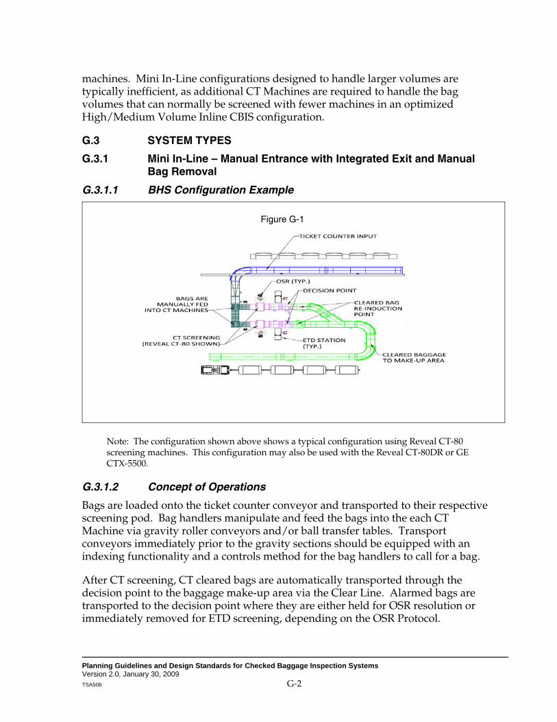
Planning Guidelines and Design Standards for Checked Baggage Inspection Systems Version 2.0, January 30, 2009 TSA506 G-2
machines. Mini In-Line configurations designed to handle larger volumes are typically inefficient, as additional CT Machines are required to handle the bag volumes that can normally be screened with fewer machines in an optimized High/Medium Volume Inline CBIS configuration.
G.3 SYSTEM TYPES
G.3.1 Mini In-Line – Manual Entrance with Integrated Exit and Manual Bag Removal
G.3.1.1 BHS Configuration Example
Note: The configuration shown above shows a typical configuration using Reveal CT-80 screening machines. This configuration may also be used with the Reveal CT-80DR or GE CTX-5500.
G.3.1.2 Concept of Operations
Bags are loaded onto the ticket counter conveyor and transported to their respective screening pod. Bag handlers manipulate and feed the bags into the each CT Machine via gravity roller conveyors and/or ball transfer tables. Transport conveyors immediately prior to the gravity sections should be equipped with an indexing functionality and a controls method for the bag handlers to call for a bag.
After CT screening, CT cleared bags are automatically transported through the decision point to the baggage make-up area via the Clear Line. Alarmed bags are transported to the decision point where they are either held for OSR resolution or immediately removed for ETD screening, depending on the OSR Protocol.
Figure G-1

Planning Guidelines and Design Standards for Checked Baggage Inspection Systems Version 2.0, January 30, 2009 TSA506 G-3
In a “Hold on Alarm” protocol, the alarmed bag will be held at the decision point for up to 30 seconds* pending OSR resolution. Upon receipt of an OSR clear decision, the bag shall be automatically conveyed to the baggage make-up area. Upon receipt of an OSR alarmed decision, the bag shall be removed by the ETD Operator for screening. If an OSR decision is not received within 30 seconds, the bag shall be removed for ETD screening.
In a “No Hold on Alarm” protocol, alarmed bags are immediately removed at the decision point conveyor. In this scenario, OSR may be continued, providing that the TSA has developed a protocol for bag storage and reconciliation. Each decision point conveyor should be equipped with a Human Machine Interface (HMI) in order for the ETD Operator to have the ability to remove the bag and thus update the bag tracking status. Upon resolution, the ETD Operator will re-induct the bag onto the conveyor immediately downstream of the decision point conveyor. A controlling method should be provided at the re-induction point so that the upstream bag is stopped at the decision point conveyor to provide a window for bag re-induction.
G.3.1.3 CT Machine Throughput Assumptions Table
Table G-2
MANUAL ENTRANCE WITH INTEGRATED EXIT AND MANUAL BAG REMOVAL MAXIMUM THROUGHPUT ASSUMPTIONS (PER CT MACHINE)
CT-80 CT-80DR CTX-5500 3DX-6000
Throughput in BPH (Based on “No Hold on Alarm”) 1301 2262 2201 2203
Level 1 Alarm Rate SSI1 SSI 1 SSI 1 SSI 1 No. of Level 1 Alarms in BPH 29 50 48 48 OSR Clear Rate SSI 1 SSI 4 SSI 1 SSI 1 OSR Resolution Time (sec) 301 304 301 201 No. of Bags to ETD 14 25 24 19 No. of BPH Resolved Per ETD Inspector 24.25 24.25 24.25 24.25 No. of ETD Inspectors Required Per CT 1 2 1 1 No. of OSR Inspectors Required Per CT (Assumes 1:1 CT / operator ratio)
1 1 1 1
No. of Additional Staff Required Per CT 1 1 1 1 1 SSI = Sensitive Security Information. Please contact TSA to obtain the SSI version of this table Information from Table 5-3 of the PGDS. 2 Information reported by Reveal. 3 Assumption based on similar system types. 4 Assumption based on similar technology. 5 Information from Table 5-5 of the PGDS, Version 1.0, October 10, 2007.
*30 Seconds OSR decision time based on Table 5-3 of PGDS, Version 1.0, October 10, 2007.
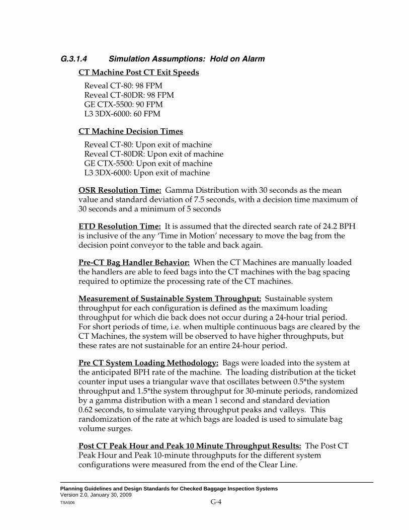
Planning Guidelines and Design Standards for Checked Baggage Inspection Systems Version 2.0, January 30, 2009 TSA506 G-4
G.3.1.4 Simulation Assumptions: Hold on Alarm
CT Machine Post CT Exit Speeds
Reveal CT-80: 98 FPM Reveal CT-80DR: 98 FPM GE CTX-5500: 90 FPM L3 3DX-6000: 60 FPM
CT Machine Decision Times
Reveal CT-80: Upon exit of machine Reveal CT-80DR: Upon exit of machine GE CTX-5500: Upon exit of machine L3 3DX-6000: Upon exit of machine
OSR Resolution Time: Gamma Distribution with 30 seconds as the mean value and standard deviation of 7.5 seconds, with a decision time maximum of 30 seconds and a minimum of 5 seconds
ETD Resolution Time: It is assumed that the directed search rate of 24.2 BPH is inclusive of the any ‘Time in Motion’ necessary to move the bag from the decision point conveyor to the table and back again.
Pre-CT Bag Handler Behavior: When the CT Machines are manually loaded the handlers are able to feed bags into the CT machines with the bag spacing required to optimize the processing rate of the CT machines.
Measurement of Sustainable System Throughput: Sustainable system throughput for each configuration is defined as the maximum loading throughput for which die back does not occur during a 24-hour trial period. For short periods of time, i.e. when multiple continuous bags are cleared by the CT Machines, the system will be observed to have higher throughputs, but these rates are not sustainable for an entire 24-hour period.
Pre CT System Loading Methodology: Bags were loaded into the system at the anticipated BPH rate of the machine. The loading distribution at the ticket counter input uses a triangular wave that oscillates between 0.5*the system throughput and 1.5*the system throughput for 30-minute periods, randomized by a gamma distribution with a mean 1 second and standard deviation 0.62 seconds, to simulate varying throughput peaks and valleys. This randomization of the rate at which bags are loaded is used to simulate bag volume surges.
Post CT Peak Hour and Peak 10 Minute Throughput Results: The Post CT Peak Hour and Peak 10-minute throughputs for the different system configurations were measured from the end of the Clear Line.

Planning Guidelines and Design Standards for Checked Baggage Inspection Systems Version 2.0, January 30, 2009 TSA506 G-5
Description of CBRA Operations: Once a bag is alarmed by the OSR operator, the ETD Operator removes the bag from the decision point for ETD search. The time that it takes an operator to remove the bag from the decision point is modeled using a normal distribution with mean 5 seconds and standard deviation 1 second. The time that it takes an operator to place the bag on the CBRA table to begin a search is modeled using a normal distribution with mean 5 seconds and standard deviation 1 second. If there are available ETD Operators, this process begins immediately. However, if a bag is alarmed at OSR while all operators are conducting searches, the alarmed bag remains at the decision point until a search is completed and the bag that was being searched is reintroduced into the system (this process is considered a reversal of the bag removal process, and is thus modeled using the same normal distribution with a mean of 5 seconds and standard deviation 1 second).
G.3.1.5 Modeling Simulation Results: Hold on Alarm
G.3.1.5.1 Hold on Alarm Protocol Throughput Results Table
Table G-3
MANUAL BAG REMOVAL (HOLD ON ALARM) THROUGHPUT RESULTS (PER CT MACHINE)
CT-80 CT-80DR CTX-5500
Sustainable System Throughput (BPH) 141 145 143 System Peak Hour (BPH) 147 151 149 System Peak 10 min. (BPH) 193 199 196 Level 1 Alarm Rate SSI 1 SSI 1 SSI 1 No. of Level 1 Alarms in BPH 31.04 31.8 31.54 OSR Clear Rate (Assumes bag is held at decision point for 30 sec) SSI 1 SSI 1 SSI 1
OSR Clear Time (Seconds) 30 30 30 No. of Bags to ETD 15.34 15.79 15.75 No. of BPH Resolved Per ETD Inspector 7.67 7.90 7.88 No. of ETD Operators Required Per CT 1 1 1 No. of OSR Operators Required Per CT (Assumes 1:1 CT / operator ratio) 1 1 1
1 SSI = Sensitive Security Information. Please contact TSA to obtain the SSI version of this table Information from Table 5-3 of the PGDS.

Planning Guidelines and Design Standards for Checked Baggage Inspection Systems Version 2.0, January 30, 2009 TSA506 G-6
G.3.1.5.2 Increases in System Throughput as a Result of Increased CBRA Staffing
Sustainable system throughput is limited by the frequency and duration of bags remaining at the decision point after being alarmed at OSR. Bags waiting at the decision point increase the likelihood that bags coming from the ticket counter will not be able to exit the machines, which can result in die back. The more ETD Operators per CT machine, the less likely that this condition will occur, resulting in higher sustainable throughput. Since the probability that this “gridlock” results in system die back is dependent on many factors (bag size dispersion, duration of bag at decision point), there is not a directly linear relationship between throughput and the number of ETD Operators. Throughput does increase with the addition of ETD Operators, but for example, doubling the number of ETD Operators per machine does not double throughput. Table G-4 below and the accompanying graph below (Figure G-2) show this change in value for each CT Machine. Space considerations must be taken into account to allow for the possibility of four ETD Operators per CT Machine. While a quantity of four ETD Operators is not feasible as shown in Table G-4, the values are given to further display the relationship between CBRA staffing and system throughput.
Table G-4
MANUAL BAG REMOVAL (HOLD ON ALARM) INCREASES IN TWO MACHINE SYSTEM THROUGHPUT
AS A RESULT OF INCREASED CBRA STAFFING
Machine CT-80 CT-80DR GE-CTX 5500
No. of ETD Operators 1 2 3 4 1 2 3 4 1 2 3 4 Avg. No. of Decision Point Delays Per Hour 4.13 0.67 0.07 0.00 5.50 2.17 0.58 0.00 6.42 2.16 0.56 0.00
Avg. Duration of all Delays (sec) 17.31 4.53 1.67 0.00 19.32 4.32 2.01 0.00 17.67 4.41 1.99 0.00
Sustainable System Throughput (BPH) 141 215 255 255 145 219 278 319 143 216 275 317
System Peak Hour (BPH) 147 224 265 265 151 228 289 332 149 225 286 330 System Peak 10 min. (BPH) 193 295 350 350 199 300 381 437 196 296 377 435

Planning Guidelines and Design Standards for Checked Baggage Inspection Systems Version 2.0, January 30, 2009 TSA506 G-7
Figure G-2
G.3.1.5.3 Observations
The limiting factor in this configuration is the occurrence of maximum capacity at CBRA when bags are occupying both OSR decision points. At this point, the system is at a high probability of die back, because bags traveling from the ticket counter cannot pass through the CT machines until the bags are removed from the OSR decision point. In the event that a bag has arrived at each of the two OSR decision points nearly simultaneously and all bags being searched at CBRA arrive simultaneously as well, the time at which the bag could wait at the decision point was observed to be up to 148 seconds in the model. This duration included simulated ETD clear time for the bag currently being searched + time for an operator to re-introduce a bag and pick up the OSR Alarmed bag. This time at the decision point can last even longer, as the rate used in the simulation is simply an average.
The system simulation also shows a less dramatic increase in throughput due to increased CBRA staffing when CT-80s are used for level 1 Screening. This is due to the fact the system reaches its CT Machine throughput limitation at 260 BPH, so there is a lower system throughput capacity for the system as a whole.

Planning Guidelines and Design Standards for Checked Baggage Inspection Systems Version 2.0, January 30, 2009 TSA506 G-8
G.3.1.6 Simulation Assumptions: No Hold on Alarm
CT Machine Pre CT Infeed/Post CT Exit Speeds Reveal CT-80: 98 FPM/98 FPM Reveal CT-80DR: 98 FPM/98 FPM GE CTX-5500: 90 FPM/90 FPM L3 3DX-6000: 30 FPM/60 FPM
CT Machine Decision Times Reveal CT-80: Upon exit of machine Reveal CT-80DR: Upon exit of machine GE CTX 5500: Upon exit of machine L3 3DX 6000: Upon exit of machine
OSR Decision Time: Gamma Distribution with 30 seconds as the mean value and standard deviation of 7.5 seconds, with a decision time maximum of 30 seconds and a minimum of 5 seconds
ETD Decision Time: It is assumed that the directed search rate of 24.2 BPH is inclusive of the any ‘Time in Motion’ necessary to move the bag from the decision point conveyor to the table and back again.
Pre-CT Bag Handler Behavior: When the CT Machines are manually loaded the handlers are able to feed bags into the CT machines with the bag spacing required to optimize the processing rate of the CT machines.
Simulated Time in Motion of ETD Operators: Since standard ETD resolution protocol does not account for OSR Storage, when used, all trips to an OSR storage location are added to the amount of time that an ETD Operator is dedicated to each handled bag. It is assumed that a bag cannot be removed by an ETD Operator until he has completed placing the bag in storage and returning to the work station (the operator is “busy”).
Measurement of Sustainable System Throughput: Sustainable system throughput for each configuration is defined as the maximum loading throughput for which die back does not occur during a 24-hour trial period. For short periods of time, i.e. when multiple continuous bags are cleared by the CT Machines, the system will be observed to have higher throughputs, but these rates are not sustainable for an entire 24-hour period.
Pre CT System Loading Methodology: Bags were loaded into the system at the anticipated BPH rate of the machine. The loading distribution at the ticket counter input uses a triangular wave that oscillates between 0.5*the system throughput and 1.5*the system throughput for 30-minute periods, randomized by a gamma distribution with a mean 1 second and standard deviation 0.62 seconds, to simulate varying throughput peaks and valleys. This

Planning Guidelines and Design Standards for Checked Baggage Inspection Systems Version 2.0, January 30, 2009 TSA506 G-9
randomization of the rate at which bags are loaded is used to simulate bag volume surges.
Post CT Peak Hour and Peak 10 Minute Throughput Results: The Post CT Peak Hour and Peak 10-minute throughputs for the different system configurations were measured from the end of the Clear Line.
Description of CBRA Operations: Once a bag is alarmed by a CT machine, OSR screening begins. The ETD Operator immediately leaves the CBRA table and removes the bag from the decision point for continued OSR screening at a nearby storage location (this to/from process is modeled using 2 aggregated normal distributions with mean 5 seconds and standard deviation 1 second. If the operator that removed the OSR-alarmed bag was conducting a search at the CBRA table at the time, he/she immediately returns to the ETD search after removing the alarmed bag from the belt.
Once OSR screening has been completed on the removed bag, the ETD Operator properly places the bag (at re-induction point if cleared, CBRA table if alarmed) once there is an operator not currently searching a bag, modeled using a normal distribution with mean 5 seconds and standard deviation 1 second. ETD Operators search bags in the order that bags were placed at the OSR storage location. If the operator reaches a bag that has been cleared by OSR, the bag is immediately placed at the re-induction point.
Throughput Limitations Due to Buildup at OSR Storage Locations: The modeled throughput is assumed to be at capacity if there are occurrences of 4 bags at both OSR storage locations simultaneously at any point during a 24-hour period. This occurrence is a indicator that the OSR’s demand on CBRA is too great by a significant margin, and that there is a small probability that the ETD Operators will be able to return to his previous operational capacity.

Planning Guidelines and Design Standards for Checked Baggage Inspection Systems Version 2.0, January 30, 2009 TSA506 G-10
G.3.1.7 Simulation Results: No Hold on Alarm
G.3.1.7.1 No Hold on Alarm Protocol Throughput Results Table
Table G-5
MANUAL BAG REMOVAL (NO HOLD ON ALARM) TWO MACHINE SYSTEM THROUGHPUT RESULTS
CT-80 CT-80DR CTX-5500 3DX-6000
Sustainable System Throughput (BPH) 260 429 428 500 System Peak Hour (BPH) 270 446 445 520 System Peak 10 min. (BPH) 356 588 587 686 Level 1 Alarm Rate SSI 1 SSI 1 SSI 1 SSI 1 No. of Level 1 Alarms in BPH 57.12 94.33 92.59 110.24 OSR Clear Rate (Assumes minimum of 30 seconds travel time to decision point)
SSI 1 SSI 1 SSI 1 SSI 1
OSR Clear Time (Seconds) 30 30 30 20 No. of Bags to ETD 28.51 47.17 47.05 44.13 No. of BPH Resolved Per ETD Inspector 23.25 23.39 23.95 25.03 No. of ETD Inspectors Required Per CT 1 1 1 1 No. of OSR Inspectors Required Per CT (Assumes 1:1 CT / operator ratio)
1 1 1 1
1 SSI = Sensitive Security Information. Please contact TSA to obtain the SSI version of this table Information from Table 5-3 of the PGDS.
G.3.1.7.2 Decreased ETD Decision Time as a Result of Increased CBRA Staffing
The throughput estimates given in Table G-5 show the throughput results as if there were only one ETD Operator per CT machine. To allow the No Hold on Alarm protocol to be correctly administered, the operator must interrupt a search if an OSR Alarm/Decision pending bag is at the decision point, in order to remove it and place it in the OSR Storage area. Clearly, this practice would increase the duration of each search, depending on how many times an ETD Operator has to leave a bag during its search. Figures G-7 and G-8 show the expected number of times that this would happen per bag, and the expected amount of time added to each search, based on simulated trials. Using these results, the times in the last column of figure G-7 were added to each search based on the number of ETD Operators used in that simulation. So, to achieve the results in the throughput table (Figure G-5), 6.048 seconds was added to the 148-second expected ETD search time.

Planning Guidelines and Design Standards for Checked Baggage Inspection Systems Version 2.0, January 30, 2009 TSA506 G-11
Table G-6
MANUAL BAG REMOVAL (NO HOLD ON ALARM) NO. OF TRIPS AWAY FROM CBRA TABLE PER BAG VS. NO. OF ETD OPERATORS
(ALL CT MACHINES EXCEPT 3DX-6000)
No. of ETD Operatorsper CT
Avg. No. of Trips awayfrom CBRA table
Avg. Time Added to Each Search (sec)
1 0.672 6.048 2 0.57 5.13 3 0.17 1.53 4 0.00 0.00
Figure G-3

Planning Guidelines and Design Standards for Checked Baggage Inspection Systems Version 2.0, January 30, 2009 TSA506 G-12
Table G-7
MANUAL BAG REMOVAL (NO HOLD ON ALARM): NO. OF TRIPS AWAY FROM CBRA TABLE PER BAG VS. NO. OF ETD OPERATORS
(L3 3DX-6000)
No. of ETD Operators per CT
Avg. No. of Trips awayfrom CBRA table
Avg. Time Added to Each Search (sec)
1 0.541 5.639 2 0.42 4.783 3 0.04 1.427 4 0 0.000
Figure G-4
G.3.1.7.3 Increases in Throughput as a Result of CBRA Staffing
Table G-8 shows the throughput results when the No Hold on Alarm protocol was simulated using 1 to 4 ETD Operators per machine. This chart is similar to Table G-4 for the “hold on alarm” configuration, except that the delays represent the occurrences where an alarmed decision was made at the OSR storage location, but CBRA was at max capacity. This chart is provided to show how this value decreases as ETD Operators are added.

Planning Guidelines and Design Standards for Checked Baggage Inspection Systems Version 2.0, January 30, 2009 TSA506 G-13
Table G-8
MANUAL BAG REMOVAL (NO HOLD ON ALARM) TWO MACHINE SYSTEM INCREASES IN THROUGHPUT AS A RESULT OF INCREASED CBRA STAFFING
Machine CT-80 CT-80DR CTX-5500 3DX-6000
No. of ETD Operators per Machine
1 2 3 4 1 2 3 4 1 2 3 4 1 2 3 4
No. of OSR Storage Area Delays per Hour
0.00 0.00 0.00 0.00 9.86 0.00 0.00 0.00 9.78 0.00 0.00 0.00 0.00 0.00 0.00 0.00
Avg. Duration of Delay (sec)
0.00 0.00 0.00 0.00 29.81 0.00 0.00 0.00 30.69 0.00 0.00 0.00 0.00 0.00 0.00 0.00
Sustainable System Through-put (BPH)
260 260 260 260 429 449 451 449 428 447 449 451 500 500 500 500
System Peak Hour (BPH)
270 270 270 270 445 467 469 467 445 465 467 469 520 520 520 520
System Peak 10 min. (BPH)
356 356 356 356 584 546 543 543 587 546 544 542 543 545 545 546
Figure G-5

Planning Guidelines and Design Standards for Checked Baggage Inspection Systems Version 2.0, January 30, 2009 TSA506 G-14
G.3.1.7.4 Observations
The maximum observed throughput for the Manual Bag Removal, No Hold On Alarm, protocol was 260 BPH when CT-80s are used because that is the throughput limit of the machine. Similarly, the system’s observed maximum throughput hovers around 450 BPH for the CT-80DR and the CTX 5500. Since the OSR clear rate is higher for the 3DX 6000, a higher system throughput is possible with one ETD operator per machine when compared to the other machines. Thus for systems where the 3DX 6000 is used, the observed peak sustainable throughput is 500 BPH. This system type is not limited by the machine’s processing rate, but that input conveyor configuration to the machine. If throughput entering the machines exceeds 500 BPH, the conveyors prior to the CT machines cannot handle the volume, and die back towards the ticket counter conveyors begins to occur.
G.3.1.8 System Conclusions
This type of system is suited for applications where space constraints prevent the installation of systems with a higher level of automation. The additional labor required to operate this type of system should be considered and weighed against other, more automated options. Typically, the Reveal CT-80 and GE-CTX 5500 are appropriate for manual entrance Mini In-Line systems because of their smaller size and lower throughput volume. The L3-3DX 6000, due to its rated throughput and continuous flow operation, was observed to yield a higher throughput in a fully integrated configuration.

Planning Guidelines and Design Standards for Checked Baggage Inspection Systems Version 2.0, January 30, 2009 TSA506 G-15
G.3.2 Mini In-Line – Fully Integrated with Manual Bag Removal
G.3.2.1 BHS Configuration Example
Figure G-6
Note: The configuration shown above shows a typical configuration using GE-CTX 5500 screening machines. This configuration may also be used with the Reveal CT-80 or Reveal CT-80DR.
G.3.2.2 Concept of Operations
Bags are loaded onto the ticket counter conveyor and transported to their respective CT screening pod. Bags are then automatically delivered to the CT Machines based on availability. The transport conveyors to the pod shall be optimized to have the proper belt speeds and bag spacing for the diverter to the individual CT screening lines. Also, the pre-CT queues shall be configured to provide proper bag spacing and orientation to the CT Machines.
After CT screening, CT cleared bags are automatically transported through the decision point to the baggage make-up area via the Clear Line. Alarmed bags are transported to the decision point where they are either held for OSR resolution or immediately removed for ETD screening, depending on the OSR Protocol.
In a “Hold on Alarm” protocol, the alarmed bag will be held at the decision point for up to 30 seconds* pending OSR resolution. Upon receipt of an OSR clear decision,
*30 Seconds OSR decision time based on PGDS, Version 1.0, October 10, 2007.

Planning Guidelines and Design Standards for Checked Baggage Inspection Systems Version 2.0, January 30, 2009 TSA506 G-16
the bag shall be automatically conveyed to the cleared baggage make-up area. Upon receipt of an OSR alarmed decision, the bag will be removed by the ETD Operator for screening. If an OSR decision is not received within 30 seconds, the bag will be removed for ETD screening.
In a “No Hold on Alarm” protocol, alarmed bags are immediately removed at the decision point conveyor. In this scenario, OSR may be continued, providing that the TSA has developed a protocol for bag storage and reconciliation. Each decision conveyor should be equipped with a Human Machine Interface (HMI) in order for the ETD Operator to have the ability to remove the bag and thus update the bag tracking status. Upon resolution, the ETD Operator will re-induct the bag onto the conveyor immediately downstream of the decision point conveyor. A controlling method should be provided at the re-induction point so that the upstream bag is controlled at the decision point conveyor to provide a merge window for bag re-induction.
G.3.2.3 System Throughput Assumptions Table
Table G-9
FULLY INTEGRATED WITH MANUAL BAG REMOVAL MAXIMUM THROUGHPUT ASSUMPTIONS (PER CT MACHINE)
CT-80 CT-80DR CTX-5500 3DX-6000
Throughput in BPH (Based on “No Hold on Alarm”) 130 (a) 226 (d) 230 (c) 300 (c)
Level 1 Alarm Rate SSI (f) SSI (f) SSI (f) SSI (f) No. of Level 1 Alarms in BPH 29 50 (d) 51 66 OSR Clear Rate SSI (f) SSI (f) SSI (f) SSI (f) OSR Clear Time (Seconds) 30 (a) 30 (d) 30 (a) 30 (a) No. of Bags to ETD 14 25 25 26 No. of BPH Resolved Per ETD Inspector 24.2 (e) 24.2 (e) 24.2 (e) 24.2 (e) No. of ETD Inspectors Required Per CT 1 2 2 2 No. of OSR Inspectors Required Per CT (Assumes 1:1 CT / operator ratio) 1 1 1 1
No. of Additional Staff Required Per CT 0 0 0 0
(a) Information from Table 5-3 of the PGDS, Version 1.0, October 10, 2007. (b) Information reported by Reveal. (c) Based on field experience with similar systems. (d) Assumption based on similar technology. (e) Information from Table 5-5 of the PGDS, Version 1.0, October 10, 2007. (f) SSI = Sensitive Security Information. Please contact TSA to obtain the SSI version of this
table Information from Table 5-3 of the PGDS.

Planning Guidelines and Design Standards for Checked Baggage Inspection Systems Version 2.0, January 30, 2009 TSA506 G-17
G.3.2.4 Simulation Assumptions
CT Machine Pre CT Infeed/Post CT Exit Speeds Reveal CT-80: 98 FPM/98 FPM Reveal CT-80DR: 98 FPM/98 FPM GE CTX-5500: 90 FPM/90 FPM L3 3DX-6000: 30 FPM/60 FPM
In the automated entrance/manual bag removal simulations, all other assumptions are identical to those used for the manual entrance configurations. As stated in section G.3.1.4, bags are inserted in the CT machines at the spacing needed for machine optimization.
G.3.2.5 Simulation Results: Fully Integrated with Manual Bag Removal
The simulations showed no significant differences in the throughput rates for manual and automated entrance. For this reason, there is no additional information in this section. Refer to sections G.3.1.4 thru G.3.1.7.
G.3.2.5.1 Observations
While there may be differences in system throughput rates as compared to the manual entrance configuration, the simulation does not take into account any spacing inefficiencies that stem from manual loading. If manual bag loaders are in fact not able to maintain bag spacing that maximizes the throughput of the machines, then an automated entrance configuration would improve throughput.
G.3.2.6 System Conclusions
This type of system is suited for applications where a system with a higher level of exit automation cannot be implemented due to space constraints. Also, the travel distance from the ticket counter to the screening matrix must be adequate to provide the proper speed and divert bag spacing needed in order to prevent die-back on the pod mainline. As with the manual entrance Mini In-Line type systems, the Reveal CT-80 and GE-CTX5500 machines are appropriate for the fully integrated Mini In-Line systems with manual bag removal locations because of their lower throughput volume. Although this configuration provides more automation and a less labor-intensive operation than the manual entrance layout, the throughput for an L3-3DX 6000 cannot be optimized due to the manual bag removal process at the decision point. The L3-3DX 6000, due to its rated throughput and continuous flow operation, was observed to yield a higher throughput in a fully integrated configuration.

Planning Guidelines and Design Standards for Checked Baggage Inspection Systems Version 2.0, January 30, 2009 TSA506 G-18
G.3.3 Mini In-Line – Fully Integrated with Automated Bag Removal
G.3.3.1 BHS Configuration Example
Figure G-7
Note: The configuration shown above shows a typical configuration using L3-3DX 6000 screening machines. This configuration may also be used with the Reveal CT 80, Reveal CT-80DR or the GE-CTX 5500.
G.3.3.2 Concept of Operations
Bags are loaded onto the ticket counter conveyor and transported to their respective screening pod. Bags are then automatically delivered to the CT Machines based on availability. Transport conveyors immediately prior to individual CT screening lines should be optimized to provide proper belt speeds and bag spacing for the diverter, as well as adequate space to prevent die-back. Also, pre-CT queues should be configured to provide proper bag spacing and orientation.
After CT screening, CT cleared bags are automatically transported to the bag make-up area via the clear line. The CT Machine alarmed bags are transported to the decision point where OSR alarm decision bags are automatically diverted to the Checked Baggage Resolution Area (CBRA) for ETD resolution. Alternatively, OSR cleared decision bags, will be conveyed to the cleared baggage make-up area. In

Planning Guidelines and Design Standards for Checked Baggage Inspection Systems Version 2.0, January 30, 2009 TSA506 G-19
order to optimize CT Machine throughput, the “Hold on Alarm” protocol will not be used in this configuration.
Where space is available, the OSR decision point shall be placed far enough downstream of the CT Machines to allow for 30 seconds1 of OSR travel time. Maximizing the amount of travel time will optimize the OSR clear rate. Each ETD resolution conveyor should be equipped with a Human Machine Interface (HMI) in order for the ETD Operator to remove the bag and thus update the bag tracking status. Upon ETD resolution, the ETD Operator shall re-induct the bag on the cleared baggage transport system. Where applicable, a controlling method should be provided at the re-induction point so that the upstream bags are stopped before the re-induction point to provide a window for bag re-induction.
G.3.3.3 System Throughput Assumptions Table
Table G-10
FULLY INTEGRATED WITH AUTOMATED BAG REMOVAL MAXIMUM THROUGHPUT ASSUMPTIONS
CT-80 CT-80DR CTX-5500 3DX-6000
Throughput in BPH (Based on “No Hold on Alarm”) 130 (a) 226 (b) 230 (c) 400 (a)
Level 1 Alarm Rate SSI (f) SSI (f) SSI (f) SSI (f)
No. of Level 1 Alarms in BPH 29 50 51 88
OSR Clear Rate (Assumes minimum of 30 seconds travel time to decision point)
SSI (f) SSI (f) SSI (f) SSI (f)
OSR Clear Time (Seconds) 30 (a) 30 (d) 30 (a) 20 (a)
No. of Bags to ETD 14 25 25 35
No. of BPH Resolved Per ETD Inspector 24.2 (e) 24.2 (e) 24.2 (e) 24.2 (e)
No. of ETD Inspectors Required Per CT 1 2 2 2
No. of OSR Inspectors Required Per CT (Assumes 1:1 CT / operator ratio)
1 1 1 1
No. of Additional Staff Required Per CT 1 1 1 1
(a) Information from Table 5-3 of the PGDS, Version 1.0, October 10, 2007. (b) Information reported by Reveal. (c) Based on field experience with similar systems. (d) Assumption based on similar technology. (e) Information from Table 5-5 of the PGDS, Version 1.0, October 10, 2007. (f) SSI = Sensitive Security Information. Please contact TSA to obtain the SSI version of
this table Information from Table 5-3 of the PGDS.

Planning Guidelines and Design Standards for Checked Baggage Inspection Systems Version 2.0, January 30, 2009 TSA506 G-20
G.3.3.4 Simulation Assumptions
CT Machine Pre CT Infeed/Post CT Exit Speeds Reveal CT-80: 98 FPM/98 FPM Reveal CT-80DR: 98 FPM/98 FPM GE CTX-5500: 90 FPM/90 FPM L3 3DX-6000: 30 FPM/60 FPM
CT Machine Decision Times Reveal CT-80: Upon exit of machine Reveal CT-80DR: Upon exit of machine GE CTX-5500: Upon exit of machine L3 3DX-6000: Upon exit of machine
OSR Resolution Time: Gamma Distribution with 30 seconds as the mean value and standard deviation of 7.5 seconds, with a decision time maximum of 30 seconds and a minimum of 5 seconds
ETD Resolution Time: It is assumed that the directed search rate of 24.2 BPH is inclusive of the any ‘Time in Motion’ necessary to move the bag from the decision point conveyor to the table and back again.
Measurement of Sustainable System Throughput: Sustainable system throughput for each configuration is defined as the maximum loading throughput for which die back does not occur during a 24-hour trial period. For short periods of time, i.e. when multiple continuous bags are cleared by the CT Machines, the system will be observed to have higher throughputs, but these rates are not sustainable for an entire 24-hour period.
Pre CT System Loading Methodology: Bags were loaded into the system at the anticipated BPH rate of the machine. The loading distribution at the ticket counter input uses a triangular wave that oscillates between 0.5*the system throughput and 1.5*the system throughput for 30-minute periods, randomized by a gamma distribution with a mean 1 second and standard deviation 0.62 seconds, to simulate varying throughput peaks and valleys. This randomization of the rate at which bags are loaded is used to simulate bag volume surges.
Post CT Peak Hour and Peak 10 Minute Throughput Results: The Post CT Peak Hour and Peak 10-minute throughputs for the different system configurations were measured from the end of the Clear Line.
OSR Transit Times by Machine Reveal CT-80: From CT1: 25.32 seconds, From CT2: 30.11 seconds Reveal CT-80DR: From CT1: 25.32 seconds, From CT2: 30.11 seconds GE CTX-5500: From CT1: 25.62 seconds, From CT2: 35.00 seconds

Planning Guidelines and Design Standards for Checked Baggage Inspection Systems Version 2.0, January 30, 2009 TSA506 G-21
L3 3DX-6000: From CT1: 27.70 seconds, From CT2: 39.50 seconds
Description of CBRA Operations: OSR-Alarmed bags are diverted to the ETD line. They are held on the ETD line until removal by an ETD Operator. Bags are removed in a first-available fashion, with the operator nearest to the end of the ETD line as the primary. The process of removing bags from the ETD line is modeled using a normal distribution with mean 5 seconds and standard deviation 1 second. After ETD search, bags are placed at the re-induction points (modeled using a normal distribution with mean 5 seconds and standard deviation 1 second. The operator then walks back to the CBRA table and either takes the next OSR-alarmed bag, or waits until there is an OSR-alarmed bag at the ETD line.
Throughput Limitations as a Result of Length of ETD Line: If the ETD line reached a maximum capacity of 6 bags, then bags were not allowed to divert to the CBRA. If bags are not allowed to divert they are stopped at the head end of the previous conveyor, and dieback can occur from that point in the system.
G.3.3.5 Simulation Results: Fully Integrated with Automated Bag Removal
G.3.3.5.1 Automated Bag Removal Protocol System Throughput Results
Table G-11
FULLY INTEGRATED WITH AUTOMATED BAG REMOVAL TWO MACHINE SYSTEM THROUGHPUT RESULTS
CT-80 CT-80DR CTX-5500 3DX-6000
Sustainable System Throughput (BPH) 260 434 434 563 System Peak Hour (BPH) 270 451 451 587 System Peak 10 min. (BPH) 356 595 595 773 Level 1 Alarm Rate SSI (a) SSI (a) SSI (a) SSI (a) No. of Level 1 Alarms in BPH 56.77 96.22 96.36 123.77 OSR Clear Rate (Assumes minimum of 30 seconds travel time to decision point) SSI (a) SSI (a) SSI (a) SSI (a)
OSR Clear Time (Seconds) 30 30 30 20 No. of Bags to ETD 27.31 47.93 48.13 49.59 No. of BPH Resolved Per ETD Inspector 23.25 23.39 23.95 25.04 No. of ETD Inspectors Required Per CT 1 1 1 1 No. of OSR Inspectors Required Per CT (Assumes 1:1 CT / operator ratio) 1 1 1 1
(a) SSI = Sensitive Security Information. Please contact TSA to obtain the SSI version of this table Information from Table 5-3 of the PGDS.

G-22
G.3
.3.5
.2
Syst
em T
hrou
ghpu
t vs
. CB
RA
Tab
le a
nd G
raph
Tab
le G
-12
INC
RE
AS
ES
IN T
HR
OU
GH
PU
T A
S A
RE
SU
LT
OF
INC
RE
AS
ED
ET
D O
PE
RA
TO
RS
: T
WO
MA
CH
INE
SY
ST
EM
WIT
H A
UT
OM
AT
ED
BA
G R
EM
OV
AL
Mac
hine
C
T-8
0 C
T-8
0DR
C
TX
-550
0 3D
X-6
000
No.
of E
TD
Ope
rato
rs
1 2
3 4
1 2
3 4
1 2
3 4
1 2
3 4
Avg
. No.
of D
ecis
ion
Poin
t D
elay
s Pe
r H
our
1.17
0.
00
0.00
0.
00
1.15
0.
47
0.00
0.
00
1.10
0.
44
0.00
0.
00
0.78
0.
19
0.00
0.
00
Avg
. Dur
atio
n of
Del
ay (s
ec)
23.1
10.
00
0.00
0.
00
22.7
417
.17
0.00
0.
00
22.9
517
.29
0.00
0.
00
13.1
57.
03
0.00
0.
00
Sust
aina
ble
Syst
em
Thr
ough
put (
BPH
) 24-
Hou
r A
vg.
217
260
260
260
216
438
456
456
219
439
451
451
283
563
618
618
Syst
em T
hrou
ghpu
t (B
PH)
Peak
Hou
r 22
6 27
0 27
0 27
0 22
5 45
6 47
4 47
4 22
8 45
7 46
9 46
9 29
4 58
6 64
3 64
3
Syst
em T
hrou
ghpu
t (B
PH)
Peak
10
min
. 29
8 35
6 35
6 35
6 29
6 60
0 62
5 62
5 30
0 60
2 61
8 61
8 38
8 77
2 74
2 74
3
Planning Guidelines and Design Standards for Checked Baggage Inspection Systems Version 2.0, January 30, 2009 TSA506

Planning Guidelines and Design Standards for Checked Baggage Inspection Systems Version 2.0, January 30, 2009 TSA506 G-23
Figure G-8
G.3.3.5.1 Observations
With automated bag removal, the limiting factor for the system in terms of throughput is the throughput capacity of the machine in every case, except for when 3DX-6000s are installed. In this case, once there are three ETD operators (total, not per CT machine), the limiting factor becomes the pre-machine queuing space available, as mentioned in section G.3.1.7.5. The pre-machine queuing space of this system should be considered for higher system throughputs so that it does not become the limiting factor for the CT Machines. Of the inline systems analyzed, this configuration has the potential for the highest throughput totals.
It was also observed that if the ETD line reached maximum capacity (6 bags), die back occurred soon thereafter. This was observed to occur only when hourly bags to CBRA exceeded the average processing rate of 24.2 BPH of the ETD operators, which was higher than the machine’s throughput rate every time, with the exception of the 3DX-6000.

Planning Guidelines and Design Standards for Checked Baggage Inspection Systems Version 2.0, January 30, 2009 TSA506 G-24
G.3.3.6 System Conclusions
This configuration presents the highest level of automation for a Mini In-Line system. Although up-front implementation costs may be higher, the long term benefits of the reduction in operational staff typically make this type of system the most viable Mini In-Line solution. For L3 3DX-6000 systems, this higher level of automation of was observed to yield an optimized machine throughput. Depending on the projected bag volume, the Reveal CT-80/80DR, and GE CTX-5500 may not be viable options for this type of system. Due to their lower throughput volumes there will be a need for additional machines and baggage handling equipment.