planning and simulation for radio access networks …
TRANSCRIPT
INVESTIGACIÓN & DESARROLLO, Vol. 21, No. 1: 17 – 36 (2021) 17 DOI: 10.23881/idupbo.021.1-2i
INVESTIGACIÓN & DESARROLLO, Vol. 21, No. 1: 17 – 36 (2021)
ISSN 2518-4431
PLANNING AND SIMULATION FOR RADIO ACCESS NETWORKS ON “SMALL CELLS”
TECHNOLOGY FOR HETEROGENEOUS ENVIRONMENTS
PLANIFICACIÓN Y SIMULACIÓN DE REDES DE ACCESO RADIO CON TECNOLOGÍA “SMALL CELLS” PARA ENTORNOS HETEROGÉNEOS
Gabriel Jaimes-Illanes
Laboratorio de Radiocomunicaciones (LRC) Universidad Privada Boliviana
[email protected] (Recibido el 24 de febrero 2021, aceptado para publicación el 15 de julio 2021)
ABSTRACT
The document presents the planning and simulation of UMTS and LTE mobile telecommunications network by the use of Small Cells technology in heterogeneous environments solutions for real foray operators in Cochabamba to achieve efficiency in resource usage in a state of high traffic load of voice and data, and therefore achieve better utilities. The methodology is based on analytical development, planning, and simulation which take place in the first instance with the collection of information. In the following steps, the project requirements were identified, a vendor technical specifications comparison was made, and the Small Cell networks were designed by radio access network planning, cell distribution and dimensioning, transportation cadasters definition, technical equipment parametrization, and frequency plan determination. Finally a procedure of simulation for coverage predictions and design validation was made. It is concluded that the project is feasible and complies with technical requirements for land survey, services demand on voice and data, coverage for indoor or outdoor environments, mobility and transport users, parameters performance on RSCP, RSRP, RSRQ signal-to-noise ratio, capacity of users, specific scenario solutions and economic benefits on deployments.
Keywords: Wireless Mobile Telecommunication Systems, LTE, UMTS, Small Cells, Indoor, Outdoor, RSCP, RSRP, RSRQ, Capacity, Coverage.
RESUMEN
El documento presenta la planificación y simulación de redes de telecomunicaciones móviles UMTS y LTE mediante el uso de tecnología Small Cell en entornos heterogéneos para proponer soluciones a operadores de incursión real en escenarios de Cochabamba para lograr eficiencia en el uso de recursos de radio frecuencia un estado de alta carga de tráfico de voz y datos, y de esta manera lograr mejores utilidades. La metodología se basa en un desarrollo analítico, diseño e implementación que tiene lugar en primera instancia en la recolección de información. En los siguientes pasos, se identificaron los requisitos del proyecto, se compararon las especificaciones técnicas de los proveedores y se diseñaron las redes con tecnología Small Cell. Se procedió a realizar una etapa de simulación y finalmente un paso de validación. Se concluyó que el proyecto es factible donde se cumplen requisitos de levantamiento territorial, servicios de voz y datos, cobertura de ambientes indoor u outdoor, mejora en gestión de usuarios de movilidad y transporte, y mejoramiento en desempeño de parámetros RSCP, RSRP, RSRQ, relación señal a ruido, capacidad de usuarios, soluciones específicas y beneficios económicos en escenarios de despliegue.
Palabras Clave: Sistemas Inalámbricos de Telecomunicaciones Móviles, LTE, UMTS, Small Cells, RSCP, RSRP, RSRQ, Capacidad, Cobertura.
1. INTRODUCTION The influence of small cells as new technological trending in the planning and dimensioning for operator’s mobile networks leads to the need to optimize scenarios of high demand for services such as the growth for multimedia applications in voice and data, congestion of users with smartphones and tablets, growth of interfering structures, as well as a focus on global network through the improvement of end user interfaces. Heterogeneous environments allow the use of various technologies for user access to the network through different systems and protocols. In this case, for different access technologies supported by small cells, which allows communication in a homogeneous way with different interfaces existing nowadays. The technology considers other features such as network adaptability, technological convergence and network element scalability1. Small Cells are a key ingredient of integrated Heterogeneous Networks (HetNets). Small cell development, implementation and optimization will effectively address
1 QUALCOMM has profiled, such as the case of Small Cells features, different scenarios for research groups on expectations of Heterogeneous
environments for diverse genres of Radio Access Cells. [24]

JAIMES-ILLANES
18 INVESTIGACIÓN & DESARROLLO, Vol. 21, No. 1: 17 - 36 (2021)
the growing demand from people who use mobile broadband and voice services in early future, to provide resources for indoor and outdoor environments2. The efficient management of mobile communication networks resources corresponds to the good dimensioning of the network's spectrum, capacity, coverage and handling of interference, for the new technologies in the transmission of voice and data. This is a requirement for actual environments on operation for provision of services, and novel implementations that are important for different sectors of society. Moreover, Cochabamba is a city in process of development, with diverse scenarios for the application of new technologies and management schemes for telecommunications operators. In the next few years will exist new hopes to confront open standards such as Long Term Evolution Advanced (LTE - A)3 and 5G New Radio (NR)4 on the way for urban and rural deployments, reduction of business operating costs, optimization of mobile network resources, and removal of obstacles to small cells deployments. The mis-optimized management of resources, in a situation with a high volume of voice and data traffic in today’s mobile networks, causes a direct relationship with the loss of operator profits by congested networks, a situation that occurs with the actual implemented capacity of a cell and bad use of network resources. Therefore, it is convenient to carry out a study, design and technology application suitable for confrontation of the feasibility in a new technology. The Small Cells solutions for the network design by the operators can satisfy the diverse requirements of the systems wireless telecommunications [12]. Since Small Cells technology provides adequate heterogeneous solutions for in-door and out-door5 environments to the growth of urban infrastructure in the city of Cochabamba, the contribution of the project was provided for the analysis of the different parameters of network quality of service in the access network nodes when using Small Cells for its operation, the use relevant in third and fourth generation technologies (3G and 4G), validation through network simulators, equipment quantification and projection of change to new technological trends at regional scenarios. In the present document the different procedures and technical vision of the project scope is developed. In the first chapter an introduction to the technology, global trending and critical application for ”Small Cells” scenarios are developed for contextualization of theory background; For the second chapter the methodology and design procedure is described, focused on radio access network segment and key performance indicators; The third chapter makes a detailed description of the selected scenarios for “Small Cells” solution deployments on consideration of cell distribution, cadasters and polygons definition; On chapter four it is shown the ink budget and coverage prediction results as part of the simulation planning methodology, making an analysis and evaluation of the performance on the solutions; Finally on chapter five, specific technical and deployment conclusions are determined for the results obtained in the project. 1.1. MOBILE GENERATIONS Through different improvements in wireless mobile communication systems, it was possible to develop technological trends based on mobile technologies to adapt into deployment changes. In this context, according to the definition of the International Telecommunications Union (ITU), 4G techniques are the setoff of modern technologies in the world of wireless broadband communications: the International Mobile Telecommunications - Advanced (IMT - Advanced) is considered as 4G and International Mobile Telecommunications - 2020 (IMT - 2020) is considered as 5G. [5]
TABLE 1 - EVOLUTION OF RELEASES BY YEAR AND NEW FEATURES [1]
Release Date Frozen New Features R99 March 2000 WCDMA air interface R4 March 2001 TD - SCDMA air interface R5 June 2002 HSDPA. IP multimedia subsystem R6 March 2005 HSUPA R7 December 2007 Enhancement to HSPA R8 December 2008 LTE, SAE R9 December 2009 Enhancement to LTE R10 March 2011 LTE – Advanced R11 September 2012 Enhancement to LTE - Advanced R12 December 2014 Dual Connectivity, FDD – TDD CA R13 March 2013 LTE unlicensed, LTE IoT R14 March 2016 C-V2X, digital Broadcast R15 July 2017 5G NR
2 Described by LYER, ZETO, SHNEIDER, and KURTZ, 2014 [3] 3 Long Term Evolution (LTE) Advance, as well as WiMAX V2, is currently considered 4th Generation Standardized Technologies for International
Telecommunications Union (ITU). [1] 4 Release 15, presented the first version of 5G New Radio Technology as Phase I, since 2018.[14] 5 Currently different scenarios for mobile radio Access technologies are considered for In – Door scenarios such as Halls, buildings, theatres and
museums. Otherwise Out-Door scenarios are useful for non-macro solutions such as academic campus, enterprise lands and small business.

PLANNING AND SIMULATION FOR RADIO ACCESS NETWORKS ON “SMALL CELLS” TECHNOLOGY…
INVESTIGACIÓN & DESARROLLO, Vol. 21, No. 1: 17 - 36 (2021) 19
a) 1th Generation (1G): The first mobile communication systems were analog and service-oriented for voice. Systems such as Advance Mobile Phone System (AMPS) and Cellular Digital Packet Data (CDPD) they were widely used in America; For example, Nippon Telephone and Telegraph (NTT), in the countries Asia and Nordic Mobile Telephones (NMT) and Total Access Communication Systems (TACS) in other parts of the world. The 800 and 900 MHz bands were used, with a bandwidth of 40 MHz, the frequencies between 869- 894 MHz for transmissions from base station to mobiles and frequencies between 824 - 849 MHz for transmissions from mobiles to base station in AMPS and TACS technologies using multiplication by division of time [7].
b) 2nd Generation (2G): The second generation networks were developed based on digital signaling of bands of narrow frequencies. By offering fully digital services, 2G technologies acquired popularity around the world. Improvements such as increased voice quality, capacity, and efficiency spectral and multiplexing were key factors for the evolution of mobile networks. With the advance, other services emerged such as a considerable degree of easy access to the WEB, digital voice and the handling of Short Message Service (SMS). Among the different technologies and their variants of second generation networks are:
▪ Global System for Mobile Communications (GSM) ▪ Code Division Multiple Access (CDMA) ▪ Time Division Multiple Access (TDMA) ▪ EDGE – 2.75 G [3].
c) 3rd Generation (3G): The third generation of wireless communication systems focuses on the process of
globalization of mobile communication. There is a predominance of the Internet and data broadband. The International Telecommunication Union (ITU) began the process of defining the standard for the third generation systems, known as International Mobile Telecommunications 2000 (IMT-2000). In Europe, the European Telecommunications Standard Institute (ETSI) was responsible for the process standardization of UMTS [10]. The standardized technologies in 3G are:
▪ UMTS Wideband CDMA (WCDMA), with downlink, speeds up to 1.92 Mbps. ▪ High Speed Downlink Packet Access (HSDPA) pushed the 14 Mbps downlink. ▪ LTE Evolved UMTS Terrestrial Radio Access (E-UTRA) with peak speeds of 100 Mbps.
International Mobile Telecommunications-2000 (IMT-2000) is on behalf of the International Telecommunications Union (ITU) for 3G. GSM proponents present Universal Mobile Telecommunications System (UMTS), an evolution of the same as the path to IMT-2000 [28]. Alternate schemes are developed in the United States, Japan, and Korea. Each scheme implies typically multiple radio transmission techniques in order to handle the evolution of 2G.To move into this "unified" 3G system, users will probably need a phone so quintuple capable of operating in an 800/900 MHz band, a 1.7 to 1.9 GHz band and a 2.5 bandit 2.69 GHz [7].
d) 4th Generation (4G): According to the definition of the International Telecommunications Union (ITU), 4G
techniques are the set of modern technologies in the world of wireless broadband communications: the International Mobile Telecommunications - Advanced (IMT - Advanced) considered as 4G. IMT-Advanced systems support high mobility applications, broadband multimedia services and a wide range of data speeds according to the demands of users and services in multiple user environments. The set of different technologies that make up 3G is called IMT- 2000. The term IMT refers to the set of IMT-Advanced and IMT – 2000 [29]. On December 62010, at the ITU World Radiocommunication Seminar 2010 (WRS - 10), in Geneva, it was defined that only two technologies are accepted to compose IMT-Advanced [2]:
▪ LTE-Advanced (LTE Release 10 & beyond) ▪ Mobile WiMAX 2.0 (802.16m, WirelessMAN-Advanced)
e) 5th Generation (5G): The 5G System is the principal focus of 3GPP Release 15. Release 15 profiles the 5G system
Phase 1, while the 5G system profiles Phase 2 which is going to be defined in Release 16. The specification of Phase 1 has involved all the 3GPP Working Groups. The 5G requirements have been identified in terms of new services and markets, the principal milestones describe different types of requirements for different 5G usage such as Enhanced Mobile Broadband (eMBB): the new requirements are identified for data-rates, traffic/connection density, user mobility, etc. Many deployments, capacity and coverage scenarios are considered, driving different service areas, some examples are indoor/outdoor, urban and rural areas, office and home, local and wide areas connectivity; Ultra Reliable and Low Latency Communications (URLLC): where many scenarios demand the consideration of very low latency and very high communications service availability. Moreover, these last milestones are conducted by implementation functionalities and features. Therefore, of these factors depend directly on the 5G framework, in consideration of affection in actual scenarios this can be reduced by suitable interconnections between the 5G system core of the 5G network, for example, to allow local hosting of the services [27]; Massive Internet of Things (mIoT). The current technology standardized as formal 5G as part of IMT – 2020 is:
▪ 5G NR (New Radio)

JAIMES-ILLANES
20 INVESTIGACIÓN & DESARROLLO, Vol. 21, No. 1: 17 - 36 (2021)
1.2. RADIO ACCESS NETWORK DOMAIN METRICS In reference to interoperability, RF6 resource management, the development of network maintenance and optimization, it is possible to consider different quantitative and qualitative domains that allow evaluating the technical performance of the network [8]. a) Capacity is defined as the degree of number of users connected to a network of telecommunications, capable of
guaranteeing a level of availability of services. It also refers to resources of a system, to perform a certain task. In a more specific context, the capacity implies the number of users capable of experiencing a level of quality.
b) Quality of Service (QoS) is the description or measurement of the general performance of a service, to quantitatively measure the quality of the service; several related aspects of the network service, such as packet loss, bit rate, throughput, delay, availability and fluctuation.
c) Coverage refers to the geographic area in which a service or application is available. It is usually applied to radio communications, but can also be used in cable services. Transmitting stations and telecommunications companies generate coverage maps that indicate to the user the area in which they offer their services [9].
d) Key Performance Indicators for the analysis and quantifiable study of the performance of 3G and 4G networks, the Key Performance Indicator (KPI's)7, which are representative metrics for the success of activities or procedures in an organization. Some of the KPIs that are considered for network planning and optimization are: ▪ RSSI (received signal strength indicator): measures the total average received power. ▪ RSCP (received signal code power): it is the power measured by a receiver in a physical communication
channel, referring to 3G. ▪ RSRP (reference signal received power): it is the power reference average according to a bandwidth, referring to
LTE. 1.3. SMALL CELLS Small Cells is a general term for low-power radio access nodes that are used both on spectrums with or without a license. They have a coverage range that varies from 10 meters to several hundred meters, compared to the tens of kilometers served by microcells as shown below, Figure 1. The elements Included in this category are femtocells, picocells, microcells, and metro cells [25].
Figure 1: Capacity of subscribers per Small Cell. Source: LYER, ZETO, SHNEIDER, and KURTZ 2014: 37.
a) HetNets use a combination of devices and technologies that work together to enable mobile voice service and
broadband access. Voice communication and data transmission are key factors for income. As consumption continues to grow, operators are looking for new strategies to face the challenge of improving the quality of experience or Quality of Experience (QoE). At a high level, HetNets represent a strategic evolution of the mobile access network in which operators increase macrocell capacity relative to demand [20]. HetNets deploy the network closer to the customer, the lowest cost location and the access nodes of low power indoors and outdoors, on street lights, roadsides and inside corporate buildings. Therefore, to facilitate HetNets deployments, infrastructure providers choose to integrate interfaces of 3G, LTE and Wi-Fi technologies inside small cells. Groups of the Third Generation Partnership Project (3GPP) are working to overcome implementation hurdles and maximize the technology of HetNet [23].
6 Radio Frequencies (RF), which correspond from 30 KHz to 300 GHz.[10] 7 Mobile communications industry uses performance indicators management machines, proper from vendors and manufacturers that correspond to the
monitoring, evaluation and optimization of the network for radio resources.
PLANNING AND SIMULATION FOR RADIO ACCESS NETWORKS ON “SMALL CELLS” TECHNOLOGY…
INVESTIGACIÓN & DESARROLLO, Vol. 21, No. 1: 17 - 36 (2021) 21
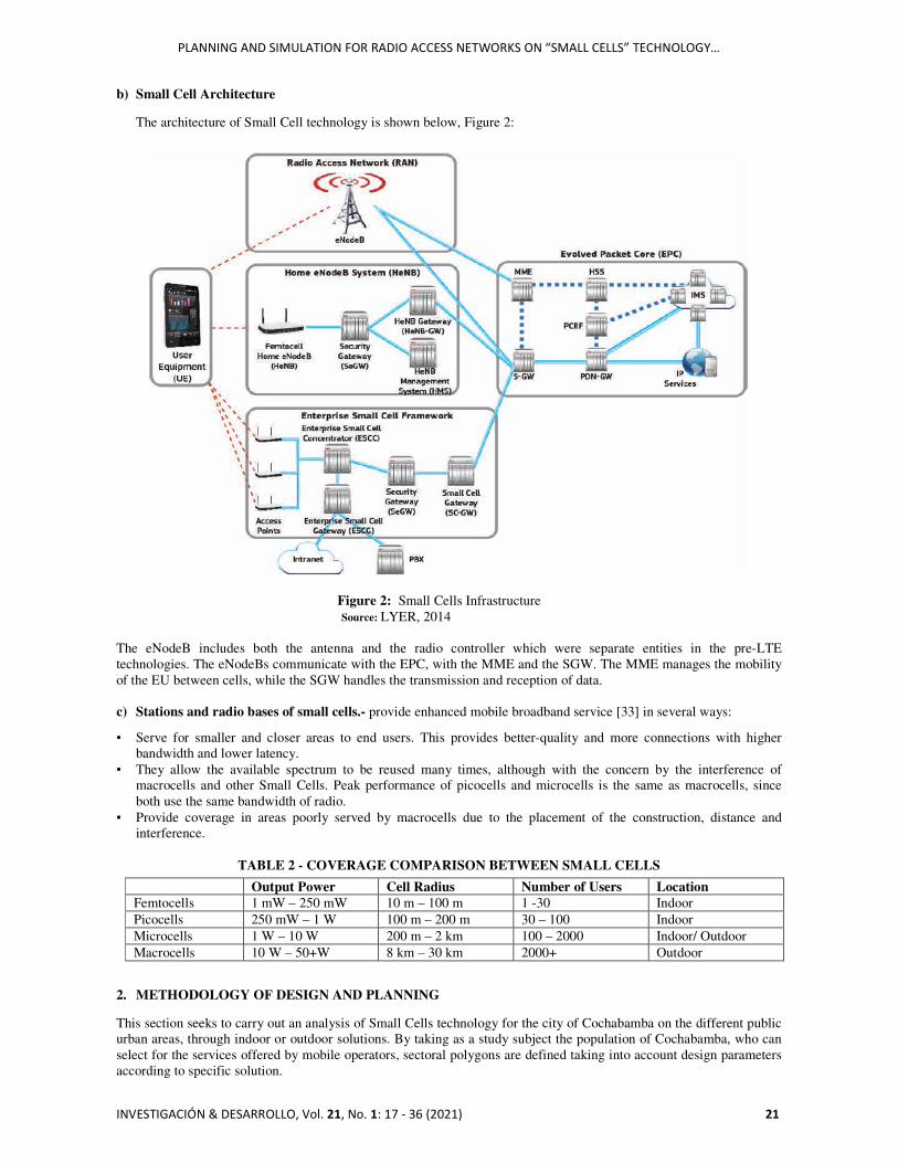
b) Small Cell Architecture
The architecture of Small Cell technology is shown below, Figure 2:
Figure 2: Small Cells Infrastructure Source: LYER, 2014
The eNodeB includes both the antenna and the radio controller which were separate entities in the pre-LTE technologies. The eNodeBs communicate with the EPC, with the MME and the SGW. The MME manages the mobility of the EU between cells, while the SGW handles the transmission and reception of data. c) Stations and radio bases of small cells.- provide enhanced mobile broadband service [33] in several ways:
▪ Serve for smaller and closer areas to end users. This provides better-quality and more connections with higher bandwidth and lower latency.
▪ They allow the available spectrum to be reused many times, although with the concern by the interference of macrocells and other Small Cells. Peak performance of picocells and microcells is the same as macrocells, since both use the same bandwidth of radio.
▪ Provide coverage in areas poorly served by macrocells due to the placement of the construction, distance and interference.
TABLE 2 - COVERAGE COMPARISON BETWEEN SMALL CELLS
Output Power Cell Radius Number of Users Location Femtocells 1 mW – 250 mW 10 m – 100 m 1 -30 Indoor Picocells 250 mW – 1 W 100 m – 200 m 30 – 100 Indoor Microcells 1 W – 10 W 200 m – 2 km 100 – 2000 Indoor/ Outdoor Macrocells 10 W – 50+W 8 km – 30 km 2000+ Outdoor
2. METHODOLOGY OF DESIGN AND PLANNING This section seeks to carry out an analysis of Small Cells technology for the city of Cochabamba on the different public urban areas, through indoor or outdoor solutions. By taking as a study subject the population of Cochabamba, who can select for the services offered by mobile operators, sectoral polygons are defined taking into account design parameters according to specific solution.
JAIMES-ILLANES
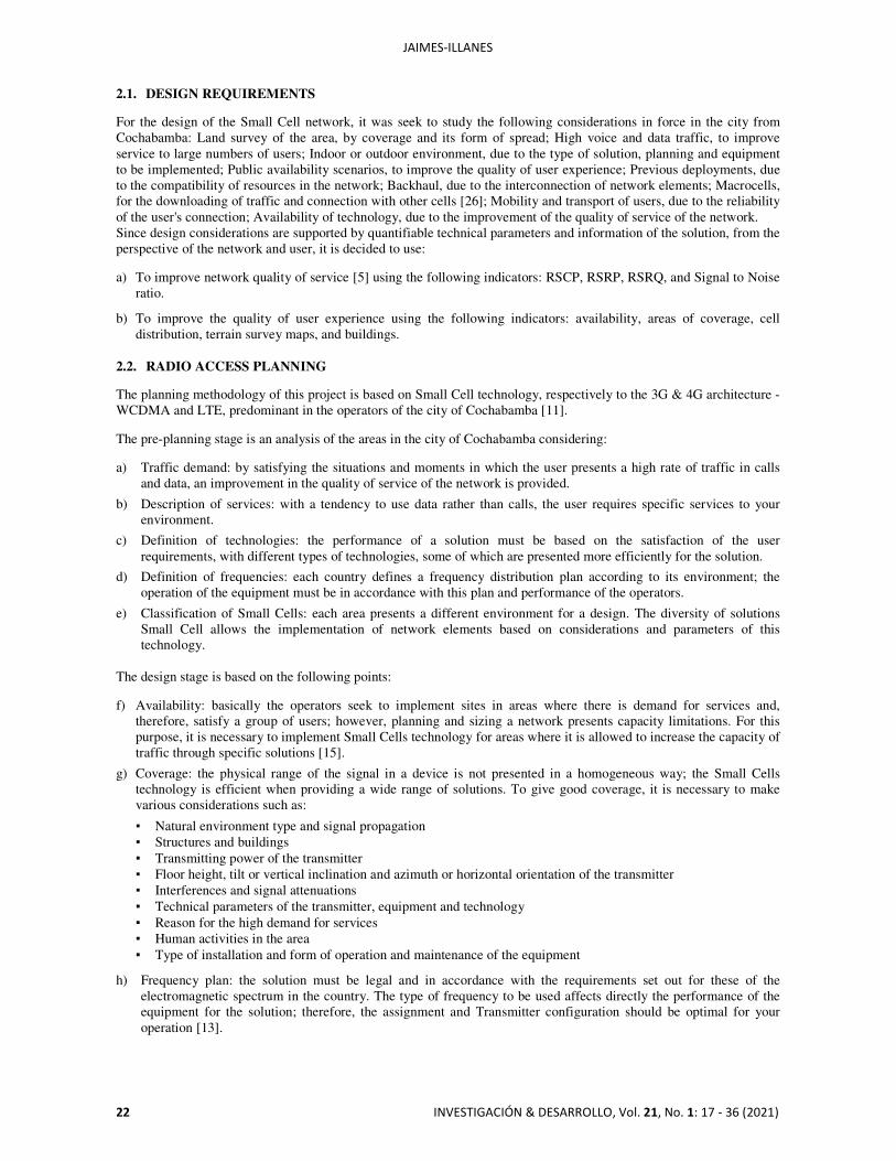
22 INVESTIGACIÓN & DESARROLLO, Vol. 21, No. 1: 17 - 36 (2021)
2.1. DESIGN REQUIREMENTS For the design of the Small Cell network, it was seek to study the following considerations in force in the city from Cochabamba: Land survey of the area, by coverage and its form of spread; High voice and data traffic, to improve service to large numbers of users; Indoor or outdoor environment, due to the type of solution, planning and equipment to be implemented; Public availability scenarios, to improve the quality of user experience; Previous deployments, due to the compatibility of resources in the network; Backhaul, due to the interconnection of network elements; Macrocells, for the downloading of traffic and connection with other cells [26]; Mobility and transport of users, due to the reliability of the user's connection; Availability of technology, due to the improvement of the quality of service of the network. Since design considerations are supported by quantifiable technical parameters and information of the solution, from the perspective of the network and user, it is decided to use: a) To improve network quality of service [5] using the following indicators: RSCP, RSRP, RSRQ, and Signal to Noise
ratio.
b) To improve the quality of user experience using the following indicators: availability, areas of coverage, cell distribution, terrain survey maps, and buildings.
2.2. RADIO ACCESS PLANNING The planning methodology of this project is based on Small Cell technology, respectively to the 3G & 4G architecture - WCDMA and LTE, predominant in the operators of the city of Cochabamba [11]. The pre-planning stage is an analysis of the areas in the city of Cochabamba considering: a) Traffic demand: by satisfying the situations and moments in which the user presents a high rate of traffic in calls
and data, an improvement in the quality of service of the network is provided.
b) Description of services: with a tendency to use data rather than calls, the user requires specific services to your environment.
c) Definition of technologies: the performance of a solution must be based on the satisfaction of the user requirements, with different types of technologies, some of which are presented more efficiently for the solution.
d) Definition of frequencies: each country defines a frequency distribution plan according to its environment; the operation of the equipment must be in accordance with this plan and performance of the operators.
e) Classification of Small Cells: each area presents a different environment for a design. The diversity of solutions Small Cell allows the implementation of network elements based on considerations and parameters of this technology.
The design stage is based on the following points: f) Availability: basically the operators seek to implement sites in areas where there is demand for services and,
therefore, satisfy a group of users; however, planning and sizing a network presents capacity limitations. For this purpose, it is necessary to implement Small Cells technology for areas where it is allowed to increase the capacity of traffic through specific solutions [15].
g) Coverage: the physical range of the signal in a device is not presented in a homogeneous way; the Small Cells technology is efficient when providing a wide range of solutions. To give good coverage, it is necessary to make various considerations such as:
▪ Natural environment type and signal propagation ▪ Structures and buildings ▪ Transmitting power of the transmitter ▪ Floor height, tilt or vertical inclination and azimuth or horizontal orientation of the transmitter ▪ Interferences and signal attenuations ▪ Technical parameters of the transmitter, equipment and technology ▪ Reason for the high demand for services ▪ Human activities in the area ▪ Type of installation and form of operation and maintenance of the equipment
h) Frequency plan: the solution must be legal and in accordance with the requirements set out for these of the electromagnetic spectrum in the country. The type of frequency to be used affects directly the performance of the equipment for the solution; therefore, the assignment and Transmitter configuration should be optimal for your operation [13].
PLANNING AND SIMULATION FOR RADIO ACCESS NETWORKS ON “SMALL CELLS” TECHNOLOGY…
INVESTIGACIÓN & DESARROLLO, Vol. 21, No. 1: 17 - 36 (2021) 23
i) Type of application: the solution is structurally specific to the urban environment, activities of the area and function; therefore, it can present harmony and functionality with the environment and, at the same time, meet user needs.
The application stage considers: j) Sizing of the network: to validate the project, it is necessary to consider the feasibility economics of the same;
counting and listing the network allows the definition of the type of equipment to be used for this purpose [14].
k) Comparison of manufacturers: there is a great diversity of technologies. When choosing a solution, must consider the efficiency of the equipment, compatibility with current operators, their types of applications, the cost of the equipment and performance in the environment.
l) Small Cells parameterization: the correct operation of a technology depends on the adequate configuration of the different technical parameters of the equipment as well as its planning background.
2.3. FREQUENCY PLAN According to the different telecommunications operators, the scalable technology for LTE (in the process of implementation) operates on the AWS8 band at 2100 MHz [22]. Likewise, the frequency bands in 1900 MHz for 3G technology in at least two operators, which is why defines to use this band for the future compatibility of the solution with the Cochabamba environment [11]: a) For LTE-A:
▪ Requested band: 2100 [MHz] ▪ Bandwidth of each carrier: 10 - 20 [MHz] ▪ Available carrier capacity: 2 carriers
b) For UMTS- HSPA9: ▪ Requested band: 1900 [MHz] ▪ Bandwidth of each carrier: 5 [MHz] ▪ Available carrier capacity: 4 carriers
2.4. MANUFACTURERS COMPARISON The products for Small Cell solutions that the different manufacturers offer are more detailed when the moment to approve a Roll - Out tender or deployment of the solution. However, based on case studies, applications, and technical information the manufacturer Ericsson has a portfolio of Small Cell technology with a set of network elements well organized and developed. The quality and performance of this manufacturer is very good due to its constant evolution and performance of technology in other scenarios; is robust due to the variety of technologies to be used, is scalable to new technological trends, presents operational safety and compatibility in the market. It has a user capacity according to the required application. The coverage is varied with respect to the standardization of Small Cell technology and has very good solutions at indoor and outdoor level. Its installation is simple, state-of-the-art and with evolving scalability10. It is the first technology to be considered by several operators in different countries. The manufacturer Huawei has a portfolio of Small Cell technology with a set of network elements quite varied and organized. The quality and performance of this manufacturer is good in outdoor environments, in which the technology is not exactly standardized; however this manufacturer presents indoor solutions oriented to the market of companies and institutions. It also has a capacity to use according to the required application. Coverage functions are presented with simplicity in its corresponding equipment installation and scalability of mobile technologies evolutions. Mobile service is the first technology to be considered by operators especially in Asian countries [16]; without dependency on specific solutions, there are still general preferences for Ericsson in this region. The manufacturer Nokia Siemens Networks has a portfolio of Small Cell technology with a set of specific and organized network elements. The quality and performance of this manufacturer are very good, with an orientation to the use of solutions indoor, and does not present a diversity of equipment. The teams present harmony and functionality in the work environment, the final comparison is detailed below. It has a user capacity according to the required application. It is not considered as the best Small Cell technology, below Ericsson and Huawei, but shown with perspectives of evolution by the performance of the technology in normal networks.
8 Currently AWS Frequency bands, which correspond for 700 [MHz] and 2.1 [GHz], are used for profiles of LTE frequency assignment bands in
different countries for South America. [17][30] 9 HSPA technology is a natural convergence technology for UMTS, with improvements on throughput, spectral efficiency and air interface protocols
that correspond to the following HSDPA, HSDPA and HSPA+, on consideration of other variations such as WCDMA, in the case of Asia, as 3.75 G. This provides the milestones for following LTE and 4G technology, LTE – Advanced.
10 In reference to Release 10, and recently for Release 15, scalability of networks is considered for Non-Stand-Alone (NSA solution on consideration of AWS band in LTE-A and NR technologies [18].
JAIMES-ILLANES
24 INVESTIGACIÓN & DESARROLLO, Vol. 21, No. 1: 17 - 36 (2021)
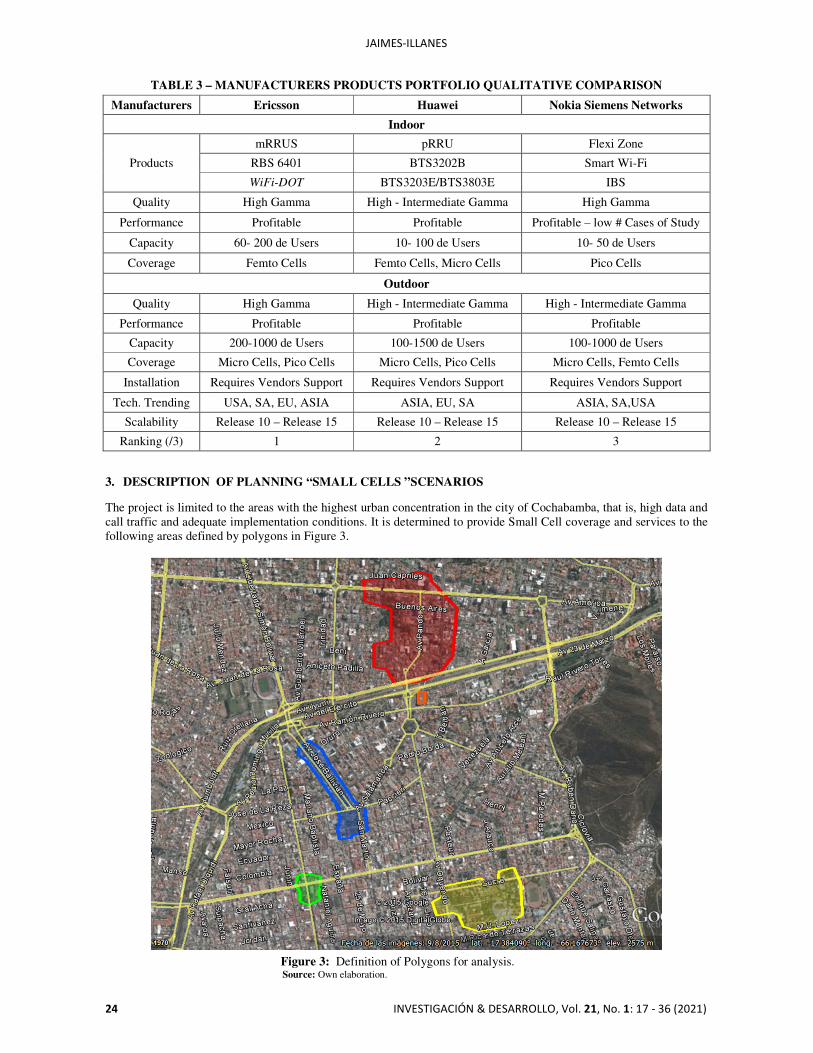
TABLE 3 – MANUFACTURERS PRODUCTS PORTFOLIO QUALITATIVE COMPARISON
Manufacturers Ericsson Huawei Nokia Siemens Networks
Indoor
Products
mRRUS pRRU Flexi Zone
RBS 6401 BTS3202B Smart Wi-Fi
WiFi-DOT BTS3203E/BTS3803E IBS
Quality High Gamma High - Intermediate Gamma High Gamma
Performance Profitable Profitable Profitable – low # Cases of Study
Capacity 60- 200 de Users 10- 100 de Users 10- 50 de Users
Coverage Femto Cells Femto Cells, Micro Cells Pico Cells
Outdoor
Quality High Gamma High - Intermediate Gamma High - Intermediate Gamma
Performance Profitable Profitable Profitable
Capacity 200-1000 de Users 100-1500 de Users 100-1000 de Users
Coverage Micro Cells, Pico Cells Micro Cells, Pico Cells Micro Cells, Femto Cells
Installation Requires Vendors Support Requires Vendors Support Requires Vendors Support
Tech. Trending USA, SA, EU, ASIA ASIA, EU, SA ASIA, SA,USA
Scalability Release 10 – Release 15 Release 10 – Release 15 Release 10 – Release 15
Ranking (/3) 1 2 3 3. DESCRIPTION OF PLANNING “SMALL CELLS ”SCENARIOS The project is limited to the areas with the highest urban concentration in the city of Cochabamba, that is, high data and call traffic and adequate implementation conditions. It is determined to provide Small Cell coverage and services to the following areas defined by polygons in Figure 3.
Figure 3: Definition of Polygons for analysis. Source: Own elaboration.
PLANNING AND SIMULATION FOR RADIO ACCESS NETWORKS ON “SMALL CELLS” TECHNOLOGY…
INVESTIGACIÓN & DESARROLLO, Vol. 21, No. 1: 17 - 36 (2021) 25
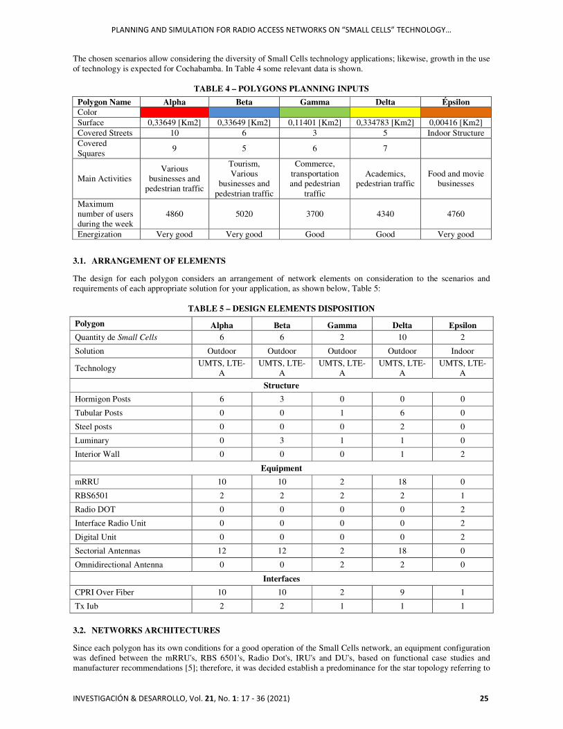
The chosen scenarios allow considering the diversity of Small Cells technology applications; likewise, growth in the use of technology is expected for Cochabamba. In Table 4 some relevant data is shown.
TABLE 4 – POLYGONS PLANNING INPUTS
Polygon Name Alpha Beta Gamma Delta Épsilon Color Surface 0,33649 [Km2] 0,33649 [Km2] 0,11401 [Km2] 0,334783 [Km2] 0,00416 [Km2] Covered Streets 10 6 3 5 Indoor Structure Covered Squares
9 5 6 7
Main Activities Various
businesses and pedestrian traffic
Tourism, Various
businesses and pedestrian traffic
Commerce, transportation and pedestrian
traffic
Academics, pedestrian traffic
Food and movie businesses
Maximum number of users during the week
4860 5020 3700 4340 4760
Energization Very good Very good Good Good Very good
3.1. ARRANGEMENT OF ELEMENTS The design for each polygon considers an arrangement of network elements on consideration to the scenarios and requirements of each appropriate solution for your application, as shown below, Table 5:
TABLE 5 – DESIGN ELEMENTS DISPOSITION
Polygon Alpha Βeta Gamma Delta Εpsilon Quantity de Small Cells 6 6 2 10 2
Solution Outdoor Outdoor Outdoor Outdoor Indoor
Technology UMTS, LTE-
A UMTS, LTE-
A UMTS, LTE-
A UMTS, LTE-
A UMTS, LTE-
A
Structure
Hormigon Posts 6 3 0 0 0
Tubular Posts 0 0 1 6 0
Steel posts 0 0 0 2 0
Luminary 0 3 1 1 0
Interior Wall 0 0 0 1 2
Equipment
mRRU 10 10 2 18 0
RBS6501 2 2 2 2 1
Radio DOT 0 0 0 0 2
Interface Radio Unit 0 0 0 0 2
Digital Unit 0 0 0 0 2
Sectorial Antennas 12 12 2 18 0
Omnidirectional Antenna 0 0 2 2 0
Interfaces
CPRI Over Fiber 10 10 2 9 1
Tx Iub 2 2 1 1 1
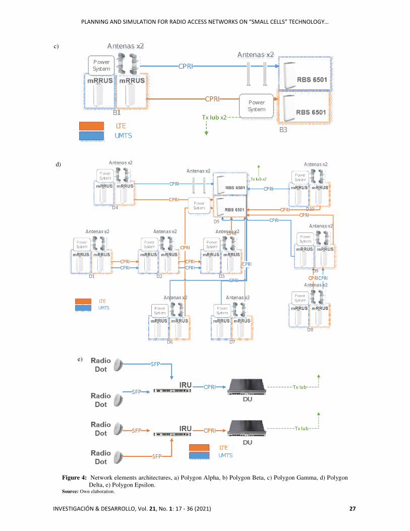
3.2. NETWORKS ARCHITECTURES Since each polygon has its own conditions for a good operation of the Small Cells network, an equipment configuration was defined between the mRRU's, RBS 6501's, Radio Dot's, IRU's and DU's, based on functional case studies and manufacturer recommendations [5]; therefore, it was decided establish a predominance for the star topology referring to

JAIMES-ILLANES
26 INVESTIGACIÓN & DESARROLLO, Vol. 21, No. 1: 17 - 36 (2021)
each RBS 6501 and mRRU for each polygon. The network element architecture for each polygon is shown below, Figure 4:
a)
b)
PLANNING AND SIMULATION FOR RADIO ACCESS NETWORKS ON “SMALL CELLS” TECHNOLOGY…
INVESTIGACIÓN & DESARROLLO, Vol. 21, No. 1: 17 - 36 (2021) 27
Figure 4: Network elements architectures, a) Polygon Alpha, b) Polygon Beta, c) Polygon Gamma, d) Polygon
Delta, e) Polygon Epsilon. Source: Own elaboration.
c)
d)
e)
JAIMES-ILLANES
28 INVESTIGACIÓN & DESARROLLO, Vol. 21, No. 1: 17 - 36 (2021)
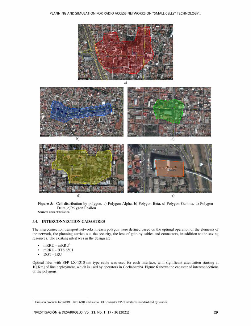
3.3. CELL DISTRIBUTION For the distribution of cells, a previous analysis of the topology was made for elements and structures that compose and critical areas for emplacement of Small Cells, with respect to the design requirements and planning scenarios explained above. The design for each polygon was different, finding a diversity of Small Cells applications and type solutions for the city of Cochabamba. Also, planning for each cell was parameterized for each cell according to the best possible performance of each sector for the Small Cells [6]. Figure 5 shows an overview of each environment: a) For polygon α, Figure 5a): A1: It is the entrance to the Boulevard, with a large concentration of people on
weekends, a variety of business and cultural activity. A2: On Beni Street, with a great concentration of food businesses, high traffic of people; is a residential area. A3: Intersection of avenues, near the Simón I. Patiño center and the UPAL University, with great concentration of students, high automotive traffic and pedestrian traffic. A4: In the parking lot of the IC Norte Supermarket, with great traffic of people and traffic, automotive, intersection of avenues and business environment. A5: On Pando Avenue, with a diversity of businesses, automotive traffic, pedestrian traffic and activity labor. A6: On Melchor Urquidi Avenue, near the intersection of the America Avenue, residential area, various businesses and pedestrian traffic.
b) For the polygon β, Figure 5b): B1: Close to the Bolivian American Center, with pedestrian traffic, high level of
private vehicular traffic and public; on Plaza Colón, at the intersection of 25 de Mayo and Venezuela streets. B2: In the center of Plaza Colón, with omnidirectional coverage, high level of pedestrian traffic all day, social and cultural activities. B3: At the southern entrance of El Prado, close to influential businesses such as Globos and Dumbo, area of work activity, with high pedestrian traffic, various businesses, social and cultural activities. B4: On Chuquisaca Street, with coverage to the pedestrian area of El Prado and nearby businesses; high pedestrian traffic, structure area for work purposes and various businesses. B5: In front of the Comteco building on La Paz Street, intersection of avenues, covering the area of El Prado, high pedestrian traffic, social and cultural activities. B6: On Oruro Street, it covers a large area of El Prado, close to the main square; high traffic pedestrian, residential area and various businesses.
c) For the polygon γ, Figure 5c): C1: It is the intersection of Ayacucho and Heroines avenues; high pedestrian traffic
area, with various business activities throughout the day, vehicular traffic zone, and meeting point and reference. Omnidirectional coverage, buildings for work and business purposes. City center. C2: It is the intersection of General Achá Street and Ayacucho Avenue, with high pedestrian traffic, with various businesses. Close to influential companies. Exit of the passage of the mail.
d) For the polygon δ, Figure 5d): D1: On Oquendo Avenue, high pedestrian traffic of students, academic activities.
Entrance to the Universidad Mayor de San Simón. Various businesses. D2: On the university pedestrian walkway, high student traffic throughout the day, activities academic and social. D3: End of the pedestrian walkway, intersection of different student campuses, near the multi building academic and IESE. Green environments. D4: Entrance to the campus of the Faculty of Legal and Political Sciences, central courtyard, exit to the street Sucre, great student traffic and academic activities. D5: It is the central courtyard of the Faculty of Humanities and Educational Sciences; high traffic of students and activities. Omnidirectional coverage. D6: It is the central courtyard of the Faculty of Economic Sciences with a large size. Study environments and green areas. High level of student traffic. Between classroom buildings and administration. Academic activities. D7: It is the entrance of the Faculty of Architecture, a large green area, and a diversity of academic activities. High pedestrian traffic.D8: In front of the laboratory classrooms and the parking lot. High pedestrian traffic. Entrance to the complex sports college. D9: In front of the Faculty of Technology, in front of the administrative building. Diversity of classrooms and environments to study. High traffic of students and administrators. D10: On Sucre Street is the entrance to the Faculty of Technology. Green areas and open environments study. Close to the main auditorium. Great concentration of students.
e) For the polygon ε, Figure 5e): E1: First floor of the Center cinema, it has a diversity of businesses and a high
traffic of people throughout the day. Omnidirectional coverage in the food court. E1: Second floor of the Cinema Center, it is an environment of waiting and meals before the cinemas. High-level of traffic of people throughout the day. Omnidirectional coverage.
PLANNING AND SIMULATION FOR RADIO ACCESS NETWORKS ON “SMALL CELLS” TECHNOLOGY…
INVESTIGACIÓN & DESARROLLO, Vol. 21, No. 1: 17 - 36 (2021) 29
a)
b) c)
d) e)
Figure 5: Cell distribution by polygon, a) Polygon Alpha, b) Polygon Beta, c) Polygon Gamma, d) Polygon
Delta, e)Polygon Epsilon. Source: Own elaboration.
3.4. INTERCONNECTION CADASTRES The interconnection transport networks in each polygon were defined based on the optimal operation of the elements of the network, the planning carried out, the security, the loss of gain by cables and connectors, in addition to the saving resources. The existing interfaces in the design are:
▪ mRRU – mRRU11 ▪ mRRU - BTS 6501 ▪ DOT – IRU
Optical fiber with SFP LX-1310 nm type cable was used for each interface, with significant attenuation starting at 10[Km] of line deployment, which is used by operators in Cochabamba. Figure 6 shows the cadaster of interconnections of the polygons.
11 Ericsson products for mRRU. BTS 6501 and Radio DOT consider CPRI interfaces standardized by vendor.

JAIMES-ILLANES
30 INVESTIGACIÓN & DESARROLLO, Vol. 21, No. 1: 17 - 36 (2021)
a)
b) c)
d) e)
Figure 6: Interconnection cadasters by polygon, a) Polygon Alpha, b) Polygon Beta, c) Polygon Gamma,
d) Polygon Delta, e)Polygon Epsilon. Source: Own elaboration.

PLANNING AND SIMULATION FOR RADIO ACCESS NETWORKS ON “SMALL CELLS” TECHNOLOGY…
INVESTIGACIÓN & DESARROLLO, Vol. 21, No. 1: 17 - 36 (2021) 31
4. RESULTS 4.1. LINK BUDGET Small Cell's traffic calculation by sector considers several technical planning parameters, moreover the information is provided only by the manufacturer once the equipment purchase was made. A traffic calculation tool for macro cells was used, compatible with the technology design Small Cell, with which parameters were configured considering the information from the manufacturer Ericsson, applications of the medium and case studies [4]. The link calculation in UMTS and LTE for the link by transmitter, receiver by Small Cell for Uplink and Downlink has default calculation values. However, the following input and output parameters were considered, Table 6:
TABLE 6 – INPUTS AND OUTPUTS PARAMETERS FOR UMTS AND LTE-A LINK BUDGET
3G Input data: 4G Input data: Total FDD Channel Bandwidth = 10 MHz BTS Total Power @Cabinet (PBTS) = 37
dBm #Tx Antennas = 2 Carrier Frequency: UL = 2110 MHz #Rx Antennas = 2 Carrier Frequency: DL = 1920 MHz
Carrier Frequency = 2100 MHz Data Rate = 2 Mb / s BS Antenna Height = 8 m Power per Connection = 37 dBm
Tx Antenna Gain = 7.5 dBi Antenna Gain = 7.5 dBi
Bs Maximum Power = 37dBm Penetration Loss = 20 dB Rx Noise Figure = 9 dB Chip Rate = 3.84 Mcps
Penetration Loss = 20 dB
3G Output data: 4G Output data: Total Tx EIRP = 43.25 dBm Maximum power available: DL = 37 dBm Rx Sensitivity = -107.8 dB Maximum power available: UL = 21 dBm
Total other gains and losses = -22.5 dB Peak EIRP = 38.66 dBm Maximum Cell Range = 0.19 Km Total Fade Margin = 31.25 dB
Minimum Received Power = -113.67 dBm
Max Cell Range = 0.20 km
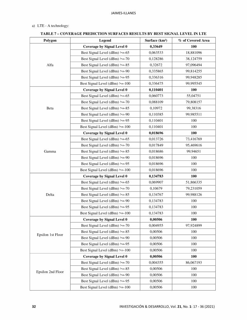
4.2. SIMULATION PROCEDURE Through a previous parameterization of each cell and site for the different planned Small Cells, it was possible to import the information regarding the required format. A project was created based on the technology standards 3GPP and the DTM map of Cochabamba was imported. For the parameterization of cells, the following were considered aspects: The tool requires engineering parameters such as position coordinates, transmission power, azimuth, tilt, propagation model, frequency bands, technologies and equipment. Since the frequency bands are 2100 MHz in LTE -A and 1900 [MHz] in UMTS, equipment was used compatible and suitable for modeling Small Cells, their Kathrein type antennas, as well as Omni-directional antennas with limited coverage. A computing polygon adequate to the required coverage was considered. High resolution was used for coverage predictions [10]. Atoll allows to create projects based on current technologies, which consider a set of configurations, equipment, predictions and simulations to be developed; UMTS and LTE - A were chosen. After the DTM height map was imported, sites with default settings were added. Each site is configured with name, longitude, latitude, altitude, pole heights and support type. We proceeded to the creation and configuration of each transmitter corresponding to each Small Cell; the following values: Antenna height, Gain and Electric tilt (default); Frequency band; Vertical and horizontal radiation pattern; Max and pilot power; and Propagation model and resolution. A coverage prediction was configured based on the signal level received by the user. According to the link calculation performed previously. 4.3. COVERAGE PREDICTIONS Through the computational polygons it was possible to analyze the coverage for the different planned polygons. Took carried out a prediction of the signal level received by the user based on the obtained DTM maps; subsequently performed a feedback of the predictions to adjust technical parameters of the Small Cells and re-simulate. In the same way, the software allowed to make reports of the percentage of surface covered in the polygon of computation at different levels defined in the legend. This indicator refers to the environment of the cells. It should be noted that the coverage of epsilon polygon is more uniform because it is an indoor solution [19]. Below is the reports shown Table 7:
JAIMES-ILLANES
32 INVESTIGACIÓN & DESARROLLO, Vol. 21, No. 1: 17 - 36 (2021)
a) LTE - A technology:
TABLE 7 – COVERAGE PREDICTION SURFACES RESULTS BY BEST SIGNAL LEVEL IN LTE
Polygon Legend Surface (km²) % of Covered Area
Alfa
Coverage by Signal Level 0 0,33649 100
Best Signal Level (dBm) >=-65 0,063533 18,881096
Best Signal Level (dBm) >=-70 0,128286 38,124759
Best Signal Level (dBm) >=-85 0,32672 97,096494
Best Signal Level (dBm) >=-90 0,335865 99,814255
Best Signal Level (dBm) >=-95 0,336316 99,948285
Best Signal Level (dBm) >=-100 0,336475 99,995545
Beta
Coverage by Signal Level 0 0,110401 100
Best Signal Level (dBm) >=-65 0,060773 55,04751
Best Signal Level (dBm) >=-70 0,088109 79,808157
Best Signal Level (dBm) >=-85 0,10972 99,38316
Best Signal Level (dBm) >=-90 0,110385 99,985511
Best Signal Level (dBm) >=-95 0,110401 100
Best Signal Level (dBm) >=-100 0,110401 100
Gamma
Coverage by Signal Level 0 0,018696 100
Best Signal Level (dBm) >=-65 0,013726 73,416769
Best Signal Level (dBm) >=-70 0,017849 95,469616
Best Signal Level (dBm) >=-85 0,018686 99,94651
Best Signal Level (dBm) >=-90 0,018696 100
Best Signal Level (dBm) >=-95 0,018696 100
Best Signal Level (dBm) >=-100 0,018696 100
Delta
Coverage by Signal Level 0 0,134783 100
Best Signal Level (dBm) >=-65 0,069907 51,866335
Best Signal Level (dBm) >=-70 0,10679 79,231059
Best Signal Level (dBm) >=-85 0,134767 99,988126
Best Signal Level (dBm) >=-90 0,134783 100
Best Signal Level (dBm) >=-95 0,134783 100
Best Signal Level (dBm) >=-100 0,134783 100
Epsilon 1st Floor
Coverage by Signal Level 0 0,00506 100
Best Signal Level (dBm) >=-70 0,004955 97,924899
Best Signal Level (dBm) >=-85 0,00506 100
Best Signal Level (dBm) >=-90 0,00506 100
Best Signal Level (dBm) >=-95 0,00506 100
Best Signal Level (dBm) >=-100 0,00506 100
Epsilon 2nd Floor
Coverage by Signal Level 0 0,00506 100
Best Signal Level (dBm) >=-70 0,004355 86,067193
Best Signal Level (dBm) >=-85 0,00506 100
Best Signal Level (dBm) >=-90 0,00506 100
Best Signal Level (dBm) >=-95 0,00506 100
Best Signal Level (dBm) >=-100 0,00506 100
PLANNING AND SIMULATION FOR RADIO ACCESS NETWORKS ON “SMALL CELLS” TECHNOLOGY…
INVESTIGACIÓN & DESARROLLO, Vol. 21, No. 1: 17 - 36 (2021) 33
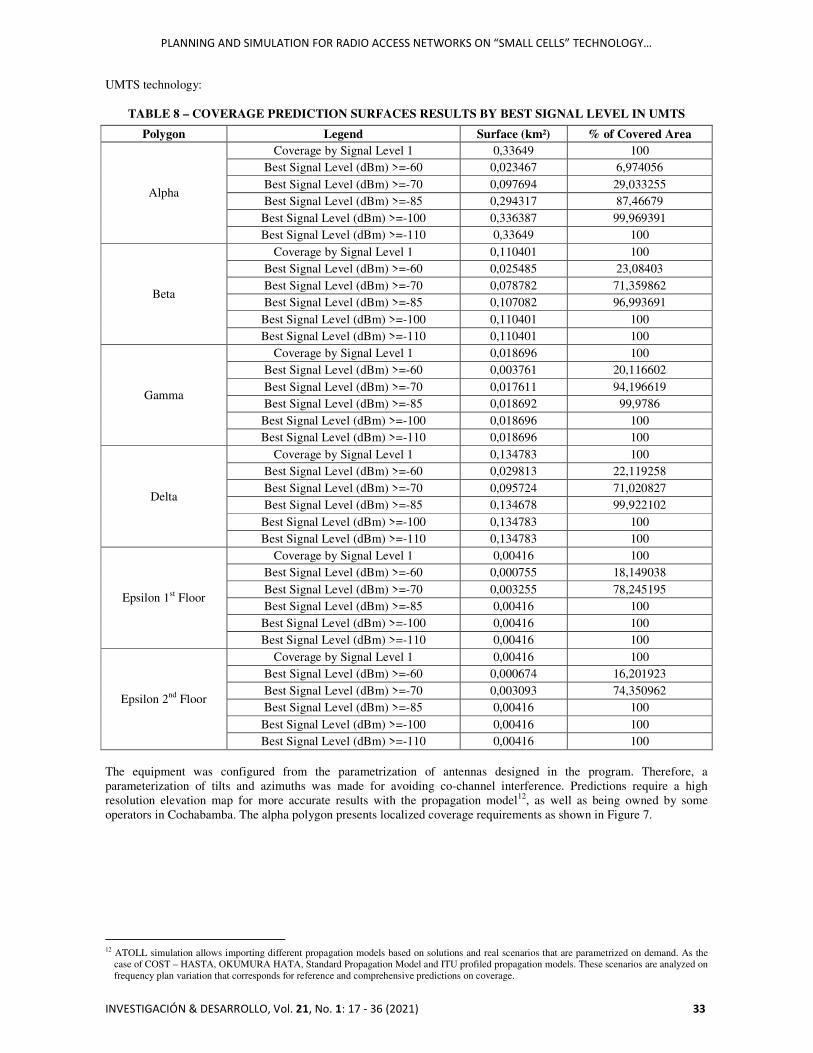
UMTS technology:
TABLE 8 – COVERAGE PREDICTION SURFACES RESULTS BY BEST SIGNAL LEVEL IN UMTS
Polygon Legend Surface (km²) % of Covered Area
Alpha
Coverage by Signal Level 1 0,33649 100 Best Signal Level (dBm) >=-60 0,023467 6,974056 Best Signal Level (dBm) >=-70 0,097694 29,033255 Best Signal Level (dBm) >=-85 0,294317 87,46679 Best Signal Level (dBm) >=-100 0,336387 99,969391 Best Signal Level (dBm) >=-110 0,33649 100
Beta
Coverage by Signal Level 1 0,110401 100 Best Signal Level (dBm) >=-60 0,025485 23,08403 Best Signal Level (dBm) >=-70 0,078782 71,359862 Best Signal Level (dBm) >=-85 0,107082 96,993691 Best Signal Level (dBm) >=-100 0,110401 100 Best Signal Level (dBm) >=-110 0,110401 100
Gamma
Coverage by Signal Level 1 0,018696 100 Best Signal Level (dBm) >=-60 0,003761 20,116602 Best Signal Level (dBm) >=-70 0,017611 94,196619 Best Signal Level (dBm) >=-85 0,018692 99,9786 Best Signal Level (dBm) >=-100 0,018696 100 Best Signal Level (dBm) >=-110 0,018696 100
Delta
Coverage by Signal Level 1 0,134783 100 Best Signal Level (dBm) >=-60 0,029813 22,119258 Best Signal Level (dBm) >=-70 0,095724 71,020827 Best Signal Level (dBm) >=-85 0,134678 99,922102 Best Signal Level (dBm) >=-100 0,134783 100 Best Signal Level (dBm) >=-110 0,134783 100
Epsilon 1st Floor
Coverage by Signal Level 1 0,00416 100 Best Signal Level (dBm) >=-60 0,000755 18,149038 Best Signal Level (dBm) >=-70 0,003255 78,245195 Best Signal Level (dBm) >=-85 0,00416 100 Best Signal Level (dBm) >=-100 0,00416 100 Best Signal Level (dBm) >=-110 0,00416 100
Epsilon 2nd Floor
Coverage by Signal Level 1 0,00416 100 Best Signal Level (dBm) >=-60 0,000674 16,201923 Best Signal Level (dBm) >=-70 0,003093 74,350962 Best Signal Level (dBm) >=-85 0,00416 100 Best Signal Level (dBm) >=-100 0,00416 100 Best Signal Level (dBm) >=-110 0,00416 100
The equipment was configured from the parametrization of antennas designed in the program. Therefore, a parameterization of tilts and azimuths was made for avoiding co-channel interference. Predictions require a high resolution elevation map for more accurate results with the propagation model12, as well as being owned by some operators in Cochabamba. The alpha polygon presents localized coverage requirements as shown in Figure 7.
12 ATOLL simulation allows importing different propagation models based on solutions and real scenarios that are parametrized on demand. As the
case of COST – HASTA, OKUMURA HATA, Standard Propagation Model and ITU profiled propagation models. These scenarios are analyzed on frequency plan variation that corresponds for reference and comprehensive predictions on coverage.

JAIMES-ILLANES
34 INVESTIGACIÓN & DESARROLLO, Vol. 21, No. 1: 17 - 36 (2021)
a) b)
c) d)
e) f)
g) h)
PLANNING AND SIMULATION FOR RADIO ACCESS NETWORKS ON “SMALL CELLS” TECHNOLOGY…
INVESTIGACIÓN & DESARROLLO, Vol. 21, No. 1: 17 - 36 (2021) 35
i) j)
k) l)
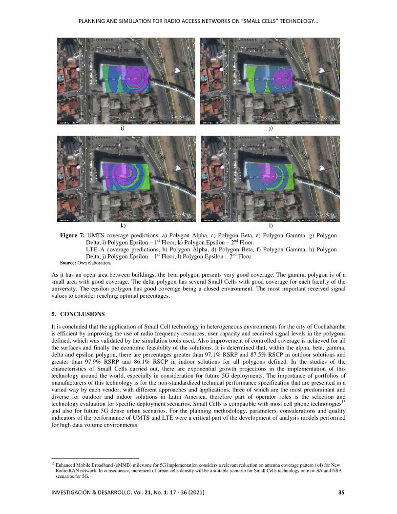
Figure 7: UMTS coverage predictions, a) Polygon Alpha, c) Polygon Beta, e) Polygon Gamma, g) Polygon Delta, i) Polygon Epsilon – 1st Floor, k) Polygon Epsilon – 2nd Floor. LTE–A coverage predictions, b) Polygon Alpha, d) Polygon Beta, f) Polygon Gamma, h) Polygon Delta, j) Polygon Epsilon – 1st Floor, l) Polygon Epsilon – 2nd Floor
Source: Own elaboration. As it has an open area between buildings, the beta polygon presents very good coverage. The gamma polygon is of a small area with good coverage. The delta polygon has several Small Cells with good coverage for each faculty of the university. The epsilon polygon has good coverage being a closed environment. The most important received signal values to consider reaching optimal percentages.
5. CONCLUSIONS It is concluded that the application of Small Cell technology in heterogeneous environments for the city of Cochabamba is efficient by improving the use of radio frequency resources, user capacity and received signal levels in the polygons defined, which was validated by the simulation tools used. Also improvement of controlled coverage is achieved for all the surfaces and finally the economic feasibility of the solutions. It is determined that, within the alpha, beta, gamma, delta and epsilon polygon, there are percentages greater than 97.1% RSRP and 87.5% RSCP in outdoor solutions and greater than 97.9% RSRP and 86.1% RSCP in indoor solutions for all polygons defined. In the studies of the characteristics of Small Cells carried out, there are exponential growth projections in the implementation of this technology around the world, especially in consideration for future 5G deployments. The importance of portfolios of manufacturers of this technology is for the non-standardized technical performance specification that are presented in a varied way by each vendor, with different approaches and applications, three of which are the most predominant and diverse for outdoor and indoor solutions in Latin America, therefore part of operator roles is the selection and technology evaluation for specific deployment scenarios. Small Cells is compatible with most cell phone technologies13 and also for future 5G dense urban scenarios. For the planning methodology, parameters, considerations and quality indicators of the performance of UMTS and LTE were a critical part of the development of analysis models performed for high data volume environments.
13 Enhanced Mobile Broadband (eMMB) milestone for 5G implementation considers a relevant reduction on antenna coverage pattern (x4) for New
Radio RAN network. In consequence, increment of urban cells density will be a suitable scenario for Small Cells technology on new SA and NSA scenarios for 5G.
JAIMES-ILLANES
36 INVESTIGACIÓN & DESARROLLO, Vol. 21, No. 1: 17 - 36 (2021)
ACKNOWLEDGMENT The author thanks the technical support provided by Dr. Gustavo Siles, Director of the Radio Communications Laboratory (LRC). To Dr. Omar Ormachea, Head of the Electronic and Telecommunications Engineering degree for the synergies and collaborative support in the publication. Also the academic collaboration and engineering evaluation by Eng. Denis Sanchez during the development of the article in terms of planning by using this new technology. Finally, the institutional and collaborative support of the teaching staff and logistics organizations of the Universidad Privada Boliviana (UPB) regional Cochabamba, Bolivia. REFERENCES [1] A. Osseiran, “5G Mobile and Wireless Communications Technology”. Cambridge, 2016. Chapter 1,2,4,9. [2] K.Wong, “Fundamentals of Wireless Communication Engineering Technologies”. Wiley, 2012. Chapter 2, 3, 9. [3] R. Lyer, Small Cells, Big Challenge: A Definitive Guide to Designing and Deploying Hetnets, Independent
Publishing Platform, 2014. [4] Y. Zhi, “Modeling and Analysis of Two-Tier HetNets With Cognitive Small Cells”, IEEE Access, 2017. [5] G. Ghatak, “Small Cell Deployment Along Roads: Coverage Analysis and Slice-Aware RAT Selection”, IEEE
Transactions on Communications – Journal Article, 2019. [6] T. Omar, “Fault-Tolerant Small Cells Locations Planning in 4G/5G Heterogeneous Wireless Networks”, IEEE
Journal Article, 2017. [7] J. M. Huidobro Moya, “Comunicaciones Móviles Sistemas GSM, UMTS y LTE”, 2013. Chapter 4, 5. [8] Y. Akaiwa, “Introduction to Digital Mobile Communication”, Wiley. 2015. Chapter 3. [9] T. L. Sarkar. “The Physics and Mathematics of Electromagnetic Wave Propagation in Cellular Wireless
Communication”. Wiley, IEEE press.2018. Chapter 2. [10] G. L. Stuber,“Principles of Mobile Communication. Fourth Edition”. Springer, 2017.Chapter 4. [11] International Telecommunications Union (ITU), “Connectivity challenges and opportunities – Bolivia. Landlocked
developing countries (LLDCs) in the Americas region”. 2016. [12] J.J. Murillo, “Fundamentos de Radiación y Radiocomunicación – 2da Edición”. Dep. Teoría de la Señal y
Comunicaciones Escuela Técnica Superior de Ingeniería, Universidad de Sevilla.2016 [13] International Telecommunications Union (ITU). Rec. UIT-R M.1224. Recomendación UIT-R m.1224
Vocabulario de términos de las telecomunicaciones móviles internacionales-2000 (IMT-2000), 1997. [14] S. Chen, Z. Zeng, and C. Guo, ‘‘Exploiting polarization for system capacity maximization in ultra-dense small cell
networks,’’ IEEE Access, vol. 5, pp. 17059–17069, Aug. 2017. [15] ‘‘Deployment strategies for heterogeneous networks,’’ Nokia Netw., Espoo, Finland, White Paper, May 2015. [16] ‘‘Ultra-dense network,’’ Nokia Netw., Espoo, Finland, White Paper, Mar. 2016. [17] J. Park, S.-L. Kim, and J. Zander, ‘‘Tractable resource management with uplink decoupled millimeter-wave
overlay in ultra-dense cellular networks,’’ IEEE Trans. Wireless Commun., vol. 15.. 2016. [18] D. López-Pérez, M. Ding, H. Claussen, and A. H. Jafari, ‘‘Towards 1 Gbps/UE in cellular systems: Understanding
ultra-dense small cell deployments,’’ IEEE Commun. Surveys 2015. [19] M. Kamel,‘‘Performance analysis of multiple association in ultra-dense networks,’’ IEEE Trans. Commun.2017. [20] ‘‘Neighborhood small cells for hyper-dense deployments: Taking HetNets to the next level,’’ Qualcomm Res.,
Qualcomm Incorp., San Diego, CA, USA. [21] Small Cell Forum, “Urban Small Cells in the real world – Document 098.05.01”. 2014. [22] Ministerio de Obras Públicas, Servicios y Vivienda, “Plan Nacional de Frecuencias” R.M. 294, 2012. [23] TSG RAN; Evolved Universal Terrestrial Radio Access (E-UTRA); Small Cell Enhancements for E-UTRA and E-
UTRAN-Physical Layer Aspects v12.1.0. 2013. [24] ‘‘Small cells & UltraSON,’’ Qualcomm Res., Qualcomm Incorp., San Diego, CA, USA, White Paper, 2014. [25] ‘‘Jump start your small cell equipment design,’’ ServiceProvider, Freescale, Austin, TX, USA, White Paper
BRSMALLCELLS REV 2, 2014. [26] O. Galinina, A. Pyattaev, S. Andreev, M. Dohler, and Y. Koucheryavy, ‘‘5G multi-RAT LTE-WiFi ultra-dense
small cells: Performance dynamics, architecture, and trends,’’ IEEE J.2015. [27] H. Kim, H. Wang, S. Lim, and D. Hong, ‘‘On the impact of outdated channel information on the capacity of
secondary user in spectrum sharing environments,’’ 2012. [28] TSG RAN; Evolved Universal Terrestrial Radio Access (E-UTRA); User Equipment (UE) Radio Transmission and
Reception, 2014. [29] P. Muñoz, I. de la Bandera, R. Barco, F. Ruiz, M. Toril, and S. Luna-Ramírez, ‘‘Estimation of link-layer quality
parameters in a system level LTE simulator,’’ 2010. [30] ITU-R, Radio Regulations 2016.URL: https://www.itu.int/pub/R-REG-RR-2016. Último acceso: Mayo 2021. [31] Frequency check. URL: https://www.frequencycheck.com/countries/bolivia Último acceso: Mayo 2021.. [32] Ley Nº 829, “Ley de adecuación para operadores de radiodifusión”. 2016. [33] Ley Nº 164, “Ley General de Telecomunicaciones, Tecnologías De Información y Comunicación”, 08 de agosto,
2011.