planning and implementation of a mega geotechnical
TRANSCRIPT
Missouri University of Science and Technology Missouri University of Science and Technology
Scholars' Mine Scholars' Mine
International Conference on Case Histories in Geotechnical Engineering
(2013) - Seventh International Conference on Case Histories in Geotechnical Engineering
01 May 2013, 2:00 pm - 4:00 pm
Planning and Implementation of a Mega Geotechnical Planning and Implementation of a Mega Geotechnical
Engineering Project in Singapore Engineering Project in Singapore
Myint Win Bo DST Consulting Engineers, Canada
A. Arulrajan Swinburne University of Technology, Australia
Follow this and additional works at: https://scholarsmine.mst.edu/icchge
Part of the Geotechnical Engineering Commons
Recommended Citation Recommended Citation Bo, Myint Win and Arulrajan, A., "Planning and Implementation of a Mega Geotechnical Engineering Project in Singapore" (2013). International Conference on Case Histories in Geotechnical Engineering. 36. https://scholarsmine.mst.edu/icchge/7icchge/session01/36
This Article - Conference proceedings is brought to you for free and open access by Scholars' Mine. It has been accepted for inclusion in International Conference on Case Histories in Geotechnical Engineering by an authorized administrator of Scholars' Mine. This work is protected by U. S. Copyright Law. Unauthorized use including reproduction for redistribution requires the permission of the copyright holder. For more information, please contact [email protected].
brought to you by COREView metadata, citation and similar papers at core.ac.uk
provided by Missouri University of Science and Technology (Missouri S&T): Scholars' Mine
Paper No. 1.22a 1
PLANNING AND IMPLEMENTATION OF A MEGA GEOTECHNICAL
ENGINEERING PROJECT IN SINGAPORE
Myint Win BO A. ARULRAJAH DST Consulting Engineers, Swinburne University of Technology,
Thunder Bay, P7B5V5, CANADA Melbourne, Vic 3122, AUSTRALIA
ABSTRACT
Implementation of mega geotechnical engineering projects requires a systematic approach and detailed planning. A mega land
reclamation and ground improvement project which consists of various components of geotechnical engineering applications was
planned and implemented in the Republic of Singapore from 1990 till 2005, a total period of one and a half decades. Due to the
extensive ground improvement required to treat the underlying highly compressible soil, with the presence of highly variable ground
profile and ground conditions due to the natural geological process, a detailed ground investigation was necessary. This was
furthermore necessary due to the importance of various critical infrastructure planned for future usage in the land reclamation site.
Extensive ground investigation was planned based on input from desk study and reconnaissance survey carried out using geophysical
method under foreshore conditions. Progressive ground investigation included ground investigation carried out in foreshore area prior
to land reclamation, on land prior to ground improvement, during and after ground improvement to assess the degree of improvement.
The ground investigation involved large numbers of in-situ tests using numerous methods and collections and testing of undisturbed
soil sample for further laboratory testing to drive necessary geotechnical parameters for design purpose or decision making for
acceptance of ground improvement works. Due to the nature and speed of the project on-site geotechnical and geotextile laboratories
were set up for characterization and quality control. In addition to the improvement of underlying soils, hydraulically filled granular
soils were required to be densified by application of deep compaction methods to minimize future immediate settlement and to
increase resistance to liquefaction. A large quantity of geotechnical instrumentation were installed and monitored for construction
control as well as performance monitoring of ground improvement works. This paper describes the procedure and process of
implementation of geotechnical works in the mega Changi East Land Reclamation and Ground Improvement project in Singapore.
INTRODUCTION
Limited land space in many countries in the East and South-
East Asian region has prompted consideration of large
reclamations projects for diverse uses such as housing,
recreation, industrial estates, sea and airport developments in
the late 1990s and early 2000s. In China, Japan, South Korea,
Hong Kong, Indonesia and Singapore, ports and airports have
been built recently on large reclaimed land. These land
reclamation projects are sited on near shore or just offshore
locations. Much land has been reclaimed using hydraulically
filled sand.
Thick soft marine clay deposits frequently underlie these large
reclamation sites. Such deposits undergo considerable
settlement over a long period of time. A suitable type of
ground improvement work is required to adopt to accelerate
consolidation of soft marine clay under large reclamations.
Land reclamation works usually involve construction of
temporary and permanent shore protection structures such as
rock bund or sheet pile walls, filling of land with imported fill
to the desired level, and implementation of ground
improvement works to strengthen underlying soils and to
densify loosely packed granular fill where necessary. The
common methods used for improving soft compressible soils
are preloading, vertical drain system and sand and stone
column; whereas dynamic compaction, vibroflotation methods
are often used for densification of granular fill. In order to
successfully implement such a land reclamation project,
geotechnical engineering plays a major role.
This paper describes the geotechnical engineering works
carried out at the various stages of the reclamation works in
Changi East Reclamation projects and to illustrate how
geotechnical engineering could be applied fruitfully in the
planning, design and construction control in various phases of
project implementation of a mega geotechnical engineering
project.
Paper No. 1.22a 2
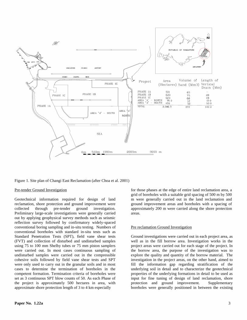
CHANGI EAST LAND RECLAMATION PROJECTS
The Changi East reclamation project consists of an extensive
amount of geotechnical engineering works, located in Changi
in the Eastern part of Singapore. It is a mega project that
involves multiple phases of construction. Phase 1 comprised
Phases 1A which commenced in 1991, 1B in 1993 and 1C in
1995, with each phase lasting about five years in duration. In
addition, two other phases of land reclamation, namely Area A
(South) and Area A (North), commenced at the same time in
1999. All major works were completed in March 2005 lasting
total project duration of 15 years. The projects include a total
hydraulic placement of 272 million cubic metres of sand in
waters of up to 15 metres deep to reclaim about 2000 hectares
of land for the extension of Changi Airport and other
infrastructure developments.
Figure 1 presents the Changi East reclamation project site and
the location of reclaimed areas in various phases. Table 1
presents the details of the various Phases of the project.
Table 1. Project specifications
PLANNING OF CHANGI EAST LAND RECLAMATION
AND GROUND IMPROVEMENT PROJECTS
Most reclamation projects carried out on soft clay require
substantial geotechnical engineering works. This type of
geotechnical engineering works necessitates proper planning
and implementation. The steps in the planning stage of Changi
East Reclamation and ground improvement project are as
follows:
(i) Identification of the Clients’ requirements.
(ii) Identification of the site conditions.
(iii) Development of design.
(iv) Preparation of Contract Documents including the
specifications.
(v) Choice of geotechnical engineering sub-
contractor.
While pre-tender ground investigation were carried out using
third party ground investigation contractor under a separate
contract, all the pre-tender ground investigations for
subsequent phases were carried out using ground
investigation crews and equipment available under the on-
going phase of the contract. Design were carried out using
data from pre-tender ground investigation and included in the
tender as exhibited design. Specifications and Bills of
quantity prepared were based on the exhibited design.
However contractors were allowed to propose alternative
design with technical and economic justifications. Contract
document was mainly based on the Institution of Civil
Engineers (ICE) Condition of contract with some
modifications and improvement based on Federation
Internationale Des Ingenieurs-Conseils (FIDIC). Special
conditions were included especially for qualification of
specialist ground investigation contractor and ground
improvement contractor. Selection of all contractors was
made based on their track records, capabilities and financial
background.
IMPLEMENTATION OF GEOTECHNICAL WORKS IN
STAGES
Geotechnical works were involved in every stages of project
implementation until hand over of the completed projects to
the owner. In many cases there could be post contract
monitoring works to monitor the long term performance of
reclaimed land. Therefore geotechnical works were planned
and implemented on a stage by stage basis. The following
geotechnical works were included in the project
implementation stages:
Ground Investigation
Geotechnical Laboratory Testing
Geotechnical Design
Ground Improvement
Geotechnical Instrumentation
Implementation of above stages will be described in details in
the following sections.
GROUND INVESTIGATION
Ground Investigation works were involved in every stage of
the project implementation of Changi East Land Reclamation
projects. Due to the extensive amount of ground investigation
works required each phase of the project had a provision for
procurement of drilling rig and accessories, specialist in-situ
testing equipment and supply of drillers and laborers by the
contractor but was managed by the prime consultants. The
followings are types of ground investigation works generally
carried out in all phases of the projects. The purposes of these
investigations varied, depending on the type and the time of
investigations.
Project Area: ha Volume of
sand: Mm³
Length of
vertical drain:
Mm
Phase 1A
Phase 1B
Phase 1C
Area A –
North
Area A -
South
501.0
520.0
524.0
91.0
450.0
65
75
68
12
52
-
28.0
49.0
13.0
50.0
Total 2,086.0 272 140.0
Paper No. 1.22a 3
Figure 1. Site plan of Changi East Reclamation (after Choa et al. 2001)
Pre-tender Ground Investigation
Geotechnical information required for design of land
reclamation, shore protection and ground improvement were
collected through pre-tender ground investigation.
Preliminary large-scale investigations were generally carried
out by applying geophysical survey methods such as seismic
reflection survey followed by confirmatory widely-spaced
conventional boring sampling and in-situ testing. Numbers of
conventional boreholes with standard in-situ tests such as
Standard Penetration Tests (SPT), field vane shear tests
(FVT) and collection of disturbed and undisturbed samples
using 75 to 100 mm Shelby tubes or 75 mm piston samplers
were carried out. In most cases continuous sampling of
undisturbed samples were carried out in the compressible
cohesive soils followed by field vane shear tests and SPT
were only used to carry out in the granular soils and in most
cases to determine the termination of boreholes in the
competent formation. Termination criteria of boreholes were
set as 3 continuous SPT blow counts of 50. As each Phase of
the project is approximately 500 hectares in area, with
approximate shore protection length of 3 to 4 km especially
for those phases at the edge of entire land reclamation area, a
grid of boreholes with a suitable grid spacing of 500 m by 500
m were generally carried out in the land reclamation and
ground improvement areas and boreholes with a spacing of
approximately 200 m were carried along the shore protection
areas.
Pre reclamation Ground Investigation
Ground investigations were carried out in each project area, as
well as in the fill borrow area. Investigation works in the
project areas were carried out for each stage of the project. In
the borrow area, the purpose of the investigation was to
explore the quality and quantity of the borrow material. The
investigation in the project areas, on the other hand, aimed to
fill the information gap regarding stratification of the
underlying soil in detail and to characterize the geotechnical
properties of the underlying formations in detail to be used as
input for fine tuning of design of land reclamation, shore
protection and ground improvement. Supplementary
boreholes were generally positioned in between the existing

Paper No. 1.22a 4
boreholes locations available in the tender documents. Ground
investigations in this stage were generally carried out in
phases starting from preliminary large-scale investigation and
supplemented with intrusive detailed ground investigation.
The detailed intrusive ground investigations usually
concentrated on boreholes, continuous quality sampling, and
selected in-situ tests for accurate characterization of the
underlying soils. Several types of in-situ tests, including the
Standard Penetration Tests, the field vane shear test (FVT), the
piezocone penetration test (CPTU), the dilatometer test
(DMT), the self-boring pressuremeter test (SBPT), the cone
pressuremeter (CPMT), the seismic cone test (SCT), BAT
permeameter (BAT) and the auto ram sounding test (RST)
were used. In addition to ground investigation of the general
area, extensive ground investigation at the pilot test area was
carried out to characterize underlying soil characteristics in
detail using conventional boring and sampling as well as
various type of specialist in-situ testing. Sampling at pilot test
locations were carried out with 150 mm large diameter
sampler especially in upper marine clay. All of the pre-
reclamation ground investigations are carried out from the
offshore jack up pontoon which is capable of sitting on the
seabed of deeper than 20 m depth. Details use and application
of such in-situ tests are described in details in Bo et.al 2012.
Ground investigation prior to ground improvement
Land reclamation are generally carried out as first target lift to
the level slightly above the maximum high tide level to use as
platform level for Prefabricated Vertical Drain (PVD)
installation as well as working level for other construction
activity such as shore protection. For this particular project
the first lift of platform level is +4mCD (with +1.6mChart
Datum being the mean sea level at the time of investigation).
In this stage, majority of ground investigation carried out
were to determine the required penetration depth for
Prefabricated Vertical Drain (PVD) and to characterize the
baseline characteristic of underlying soils at the proposed
geotechnical instrument cluster locations. For the
determination of PVD penetration length, CPTs were carried
out with a suitable regular grid pattern to determine the
bottom of compressible layer as well as competent layer for
PVD anchorage. In addition CPT data were also used to
detect the possible disturbance and seabed level change due to
hydraulic filling of sand in the land reclamation process as
well as any mud trap in the reclaimed fill which could affect
the settlement magnitude, bearing capacity and stability of the
upcoming infrastructure. Those boreholes carried out at the
geotechnical instrument cluster location include sampling and
in-situ filed vane tests and in some places CPTs and
dissipation tests are also involved.
Ground investigation during ground improvement
Ground investigation during ground improvement are
generally carried out at the geotechnical instrument cluster
location to confirm the degree of improvement where
substantial improvement of ground close to specification
requirements is detected through the instrument monitoring
data. Such ground investigation consists of boring and
sampling, filed vane shear tests, CPTs and CPTUs at the
instrument cluster locations.
Post-improvement ground investigation
In the Changi projects, post-improvement ground
investigations were usually carried out in the underlying clay
to verify its extent of improvement from pre-compression
when monitoring results from geotechnical field instruments
indicated that the improvement achieved the specified degree
of consolidation. In this stage of investigation, the same types
of ground investigation methods as those used prior to
reclamation were employed. One unique feature of this stage
of investigation is that careful interpretation is required
because of the transient porewater pressure condition and
hence the none-equilibrium effective stress state in the ground.
The investigation methods carried out in the post-
improvement stage at Changi site included boring, sampling,
the FVT, CPT and CPTU tests, DMT, SBPT, CPMT, SCT and
RST tests.
Boring and sampling were generally carried out from the
surcharge level and through the sand fill. Figure 6 shows a
comparison of the pre- and post-improvement borehole logs
and FVT results together with other geotechnical parameters
obtained from the laboratory tests. Although settlement
observations from settlement plates and selected laboratory
results indicated that the clay had generally achieved the
targeted degree of consolidation and field excess pore
pressures, laboratory results, such as the undrained shear
Strength and the pre-consolidation pressure could show a
degree of improvement that was lower than expected. In
reality, undrained shear strength could be under-estimated in
the laboratory due to sample disturbance. Pre-consolidation
pressure could also be under-predicted by the consolidation
test due to the chosen method of testing, interpretation and
non-linearity of the stress strain behavior of the soil. These
were widely discussed, for example by Arulrajah et al. (2005),
Arulrajah et al. (2006) and Bo et al. (1999).
It is a well-known behavior that the average degrees of
consolidation as indicated by field settlement observations and
that inferred by the effective stress gain are usually different,
with the effective stress gain generally lags behind. However,
as the main purpose of most pre-compression of clay strata in
land reclamation projects is usually to eliminate future
settlement, achieving a degree of consolidation defined in
terms of percentage of soil compression achieved will be a
more relevant criterion to adopt.
Table 2 shows numbers of specialist in-situ tests carried out in
5 phases of Changi East Land Reclamation and Ground
Improvement projects. It can be seen that extensive numbers
of CPTs were carried out in the projects.

Paper No. 1.22a 5
Table 2. Total number of specialist in-situ tests
Projects
Phase 1A Phase 1B Phase 1C
Area A
(North)
Area A
(South) Total
CPT 2424 4,546 6,537 885 2,127 16,339
FVT 75 292 306 72 119 864
DMT 0 11 10 2 4 27
SBPT 0 11 10 2 4 27
BAT 0 8 27 2 6 54
CPMT 0 85 31 0 0 116
RAM sounding 78 1,463 0 0 243 1,784
Seismic cone 0 3 0 0 0 3
In-situ
permeability test 0 0 10 0 3 13
GEOTECHNICAL LABORATORY TESTING
Due to the nature of project and large quantity of samples
expected to be collected and tested together with a possibility
of urgency in obtaining geotechnical parameters during
project implementation in many cases, each contract has a
provision for setting up of advanced on site material testing
laboratory. All the laboratories are under controlled
environment with majority of laboratory equipment are
automated in nature. Each laboratory is equipped with all
equipment required for classification test such as various
scales of balances, oven, thermometers, sieves, hydrometers,
Casagrande cups, dessicators, laboratory vane and sample
extruder etc:. In addition to the basics equipment required for
classification tests following equipment are also set up and
installed in the laboratory.
Oedometer
NGI Direct Shear Equipment
Hydraulic Rowe cellConstant rate of strain
consolidation cell
Triaxial equipment capable of carrying out all types
of shear strength tests
Bishop and Horsley stress path triaxial cell GDS
pressure and volume controllers
Automatic data logging system for all of the above
equipment
Almost all the equipment was supplied by Wykeham
Farrance, UK. The laboratories are capable of carrying out
quality control tests on geotexile such as, tensile strength,
Apparent Opening Size (AOS) tests and Discharge capacity
tests for PVD. Testing for other geotexile parameters and rock
testing were carried out at third party accredited laboratory in
Singapore. Electron-microscope and X-ray reflection tests for
clay mineralogy determination were carried out in British
Geological Survey in United Kingdom.
GEOTECHNICAL DESIGN
Geotechnical design in land reclamation involves magnitude
of settlement calculations in each stage of filling to determine
volume loss considering construction sequences. Design and
stability analyses of various types of shore protection
structures such as rock berms, breakwater, rock groynes and
sheet pile wall etc:. Ground improvement design were also
carried out for improving compressible soils to accelerate the
consolidation process as well as improving loosely fill
granular soil to increase the resistance to liquefaction
potential as well as to minimize the elastic immediate
settlement upon application of the additional stresses.
Shore protection Design
As the reclamation fill is as thick as 21 m at the edge of the
land reclamation, net fill thickness after the completion of
consolidation settlement could be as thick as 23 m. In order to
be able to successfully construct the very high shore
protection structure on the soft marine clay as well as to
maintain the stability of the berm in long term condition, a
suitable sand key was provided in order to improve the global
stability as well as sliding of the structure. Provision of sand
key required removal of soft upper marine clay to three to
four meters depth which also helps in minimizing the
settlement of the shore protection structure. Several stability
Paper No. 1.22a 6
berms were also provided to improve the overall stability of
the shore protection structure. Overheights were provided
both at the crest of shore protection structure as well as
intermediate stability berms based on the settlement
calculations. While overheights at the crest were allowed to
nicely complete the crest elevation at the long-term proposed
finished levels, overheights at the intermediate levels were
also allowed to finish the elevation above high tide level or
well below low tide level in order to prevent the navigation
vessels not to be grounded at any time.
At the corner of land reclamation where significant wave and
current are predicted from hydraulic model, a suitable
breakwaters and rock groynes are provided. Stability of such
structures was checked and settlements of the crest were
predicted to provide sufficient overheight to finish at the
designed elevations. All the stability check were carried out
using Geosolve finite different software while settlement
analyses were carried out using Consol99 or Plexis finite
element modeling.
In Phase 1A area where future jetty development is required,
a vertical retaining wall using sheet pile was installed. As the
retained height of the sheet pile was as high as up to 17
meters above seabed levels with penetration length of less
than 30 m, support from both sides of the wall using raker
piles which were strengthen by compression toe pin and
tension anchor at the passive side and active side respectively.
Stability, bending moment and shear forces on the wall were
checked using either WALLAP or Plaxis finite element
software. The length of shore protection works in this project
is about 10 km. A total of 3 million m3 of rock was used to
form the shore protection. Extreme care was taken in the
construction of the rock bunds which were closely monitored
by soil instruments such as inclinometers and piezometers.
The observational method used in the construction of these
works has been described by Choa, (1994). The other half of
the boundary at Phase 1A, was retained by a vertical sheet
pile retaining structure using sheet-piles and pipe-piles since
the area will be used for future berthing facilities. A total of
7,276 nos of sheet and box piles of 600mm width were driven
over 3.9 km length along the boundary and 1590 nos. of raker
pipe piles of 610mm diameter were driven to cater for
compression and tension forces arising from berthing of
vessels on the wharf structure to be built in front of the
retaining structure. The landside pipe piles were flushed out
and ground anchors with 1000kN working load were installed
below the toe of these piles.
GROUND IMPROVEMENT
In the land reclamation project ground improvement were
required to accelerate the consolidation process of underlying
soils as well as improving the loosely deposited granular fill
to be able to withstand the dynamic and seismic forces as well
as to minimize the elastic settlement of granular soil upon
application of additional stresses. At some localized locations
where excessive mud trap was occurred a specialized soil
improvement method such as stone or sand column
installations was required. Each method of ground
improvement design is described in the following section.
Improvement of Compressible Soils
Generally prefabricated vertical drains were designed to
improve the drainage system of the seabed compressible soils.
The spacing of vertical drain was selected to achieve 90%
degree of consolidation with fill and surcharge load after
taking into consideration the submergence effect caused by
sinking of fill below groundwater level within a certain
surcharge period. For such cases at least a minimum
preloading pressure of equivalent to two to three meters
thickness of sand (35 to 50 kPa) were achieved over and above
of fill load. For the locations where no special treatment was
required for future load, soil improvement works were carried
out to achieve 90 % degree of consolidation due to fill load
plus a general future load of 20 kPa. At locations where future
loads were known, the equivalent magnitude of surcharge load
after taking into consideration of submergence effect and
ground water level rising were applied. PVD spacings were
designed based on thickness, parameter of underlying clay and
duration allowed for surcharge period. As the reclamation
covers an extensive area, the soil profile and characteristic of
the soil are different from one area to another. In addition to
that the future loading and timing of land usage are different
within the area. Therefore design of the soil improvement
works were based on the existing soil profile, future land use
and allowable duration for soil improvement works. The
acceptance criteria of the soil improvement works were also
varied since the design criteria and future land use varied.
Details of the basic design concept shown in Table 3 were
discussed by Bo et al. (2000) and Choa et al. (2001). It can be
seen in the table that vertical drain spacings used are ranging
between 1.5 m to 2.0 m square spacings depending on the
duration of surcharge period. The magnitudes of surcharge are
reclamation was carried out under four phases since vast
quantities of fill material and prefabricated vertical drains
were required. As the majority of the reclamation area is
underlain by up to 50m thick, highly compressible layer of
Singapore Marine Clay, about 140 million meters length of
prefabricated vertical drains in combination with up to 8m
thick of surcharge have been used to improve the engineering
properties of the seabed soils. The total area of soil
improvement is about 1200 hectares.
Paper No. 1.22a 7
Table 3. Details of soil improvement design with PVD in Changi East Reclamation Project (after Bo et al. 2000)
Area Year of
Thickness
Type Future Design Design Surcharge Specified
Design of clay:
m
of clay land use spacing
sq.
grid::m
surcharge
el. mCD
period:
months
acceptance
criteria
A 1992 20 - 40 Marine
clay
Runway 1.5 + 10 18 90% consolidation of the
fill and surcharge load
B 1992 10 - 35 Marine
clay
Taxiway 1.8 + 8.5 18 90% consolidation of the
fill and surcharge load
C 1995 20 - 30 Marine
clay
Infrastructure
area
1.8 + 8.5 24 90% consolidation of the
fill and surcharge load
D 1995 30 - 45 Marine
clay
Infrastructure
area
1.8 + 9.5 24 90% consolidation of the
fill and surcharge load
E 1995 30 - 45 Marine
clay
Others 1.8 + 8.5 24 90% consolidation of the
fill and surcharge load
F 1995 20 - 40 Marine
clay
Roads 1.5 + 8.5 12 90% consolidation of the
fill and surcharge load
G 1998 40 Marine
clay
Future
material
stockpile area
1.5 +12 12 90% consolidation of the
fill and surcharge load
H 1998 40 Marine
clay
Infrastructure 1.8 + 10 18 90% consolidation to
finished level to +5.5m
CD + future load 20 kPa
I 1998 40 Marine
clay
Infrastructure 1.5 + 10 12 90% consolidation of the
fill load to +5.5m CD +
20 kPa
J 1998 10 - 35 Marine
clay
Infrastructure 1.8 + 9 18 90% consolidation to
finished level to +5.5m
CD + 20 kPa
K 1992 10 - 20 Soft
slurry
Infrastructure 2.0
3 passes
+ 9 36 90% consolidation of the
fill and surcharge load
Pilot tests
In order to successfully implement the ground improvement
works with the proposed design, pilot tests were carried out in
the early stage of each phase to verify the performance of the
proposed design. Any deviation of performance from the
prediction could bring attention to the implementing engineer
and necessary remedial action or correction can be made based
on the actual performance monitoring data.
Most pilot test areas consist of areas with prefabricated
vertical drains with various spacing as well as control area
with no vertical drain but applied the same magnitude of
preload. In some pilot tests a few different types of
prefabricated vertical drains were installed. While most pilot
test areas had separations between one type of spacing to
another, in one of the pilot tests no separation was provided in
order to observe the boundary effect. The entire pilot area in
each phase was applied with same magnitude of preload.
Instrument cluster consist of various types of geotechnical
instrument were installed in each sub-area of pilot test with
and without prefabricated vertical drain. Every geotechnical
instrument cluster consists of deep settlement gauges,
multilevel settlement gauges, both types of pore pressure
piezometers (pneumatic and vibrating wire piezometers),
inclinometers and surface settlement gauge. While most of the
instrument clusters were installed after formation of general
platform level of +4 mCD but before installation of PVD,
instrument cluster in the control area was installed under
offshore condition from the offshore instrument platform in
order to catch the base line condition of pore pressure as well
as to catch magnitude of settlement occurred during the
placement of general fill level to +4 mCD. In addition, a deep
reference point is usually installed in the instrument cluster in
the control area in order to achieve the accuracy of survey
works carried out for monitoring exercise. Details of the pilot
test area can be found in Bo et al. (1999b), Choa and Bo
(2000), Choa et al., 2001 and Bo et.al (2003). Details of the
pilot areas carried out in each of the phase are shown in table
4.
Paper No. 1.22a 8
Table 4. Details of pilot areas (after Choa et al. 2001)
Area No. of
test plots
Type of tests
plots spacing (m)
Type of vertical drain Objective
1
2
3
4
4
11
(a) 1.5
(b) 1.7
(c) 2.0
(d) No drain
(a) 2.0
(b) 2.5
(c) 3.0
(d) No drain
(a) 1.5
(b) 1.8
(c) 2.0
(d) 1.5
(e) 1.8
(f) 2.0
(g) 1.5
(h) 1.8
(i) No drain
Colband CX 1000
Colband CX 1000
Colband CX 1000
Colband CX 1000
Colband CX 1000
Colband CX 1000
Colband CX 1000
Colband CX 1000
Colband CX 1000
Mebra (Holland) MD-7007
Mebra (Holland) MD-7007
Mebra (Holland) MD-7007
Mebra MD-7007 (Korea)
Mebra MD-7007 (Korea)
To check the performance of vertical
drain with typical installation rig and
to verify soil and smear parameter
To check possible maximum spacing
To check long-term performance
Comparative study on material
To check boundary effect
To check partial penetration effect
IMPROVEMENT OF GRANULAR FILL
An area of about 114 hectares was improved by deep
compaction methods through 7 to 10m thickness of granular
fill profile. Three types of deep compaction methods namely
dynamic compaction, vibroflotation and Muller Resonance
Compaction (MRC) were deployed to densify the granular
soil. The areas where the three different types of compaction
methods were used along the runway and taxiways in Phase
1B are shown in Figure 2. The dynamic compaction method
was deployed in Phase 1A where about 100 hectares of land,
immediately behind the wharf structure, is to be utilized for
low-rise infrastructure development. Dynamic compaction
was used in other Phases where the area where the required
depth of compaction was 5 to 7 metres. Details of the
compaction methods use and combinations of spacing, energy
and equipment used are shown through Table 5 to 9. In Phase
1A project, in order to avoid any damage to the sheet pile
retaining structure, the area from the wharf face up to a
distance of 30 metres was compacted using the vibroflotation
method.The vibroflotation and MRC methods were adopted in
the areas where the required thickness of compaction was 7 to
10 metres. Areas compacted with Dynamic compaction (Area
A) and vibroflotation (Area B) in Phase 1 A projects are
shown in Figure 3.
The specifications called for densification were a minimum
cone resistance of 15 MPa, and 12 MPa for runway, taxiway
and associated areas respectively. For the other areas where
compactions are required, the compaction is carried out for the
top 5m and the minimum requirement was a cone resistance of
10 MPa.
Each of the three compaction methods has its own advantages
and disadvantages depending on the site and soil condition in
the various areas. Nevertheless, the specified degree of
compaction was achieved in all the areas. The dynamic
compaction method can produce a uniform degree of
densification in each layer. However, the degree of
densification varied with the depth. Furthermore, the depth of
compaction is limited. The Muller Resonance Compaction
method is able to compact with a wider spacing. However,
frequent maintenance of the probe is required due to wearing
of the probe. With MRC, the degree of densification achieved
is uniform along the depth, but it varied with the distance from
the probe points. The compactable depth is also limited due to
the flexibility of the probe. The vibroflotation can compact to
a greater depth. The degree of densification is uniform along
the depth, but also varies with distance from the probe points.
It requires a smaller spacing grid and a supply of water.
Details on densification works using the three methods of
compaction are described in Choa et al., (1997, 2001) & Bo
et.al (2009).
GEOTECHNICAL INSTRUMENTATION
Changi East Reclamation Project is a multi-phase land
reclamation project which included vast areas of soil
improvement works. Since prefabricated vertical drains were
used for acceleration of consolidation process, several
geotechnical instruments were required to monitor the
settlement and pore pressure dissipation hence effective stress
gain. Edges of newly reclaimed land are either retained by
vertical retaining structure or coastal shore protection rock
bund with suitable slopes and berms. Therefore sufficient
monitoring and measurement of magnitude and rate of
movement were essential in order to complete the construction
of retaining structures without stability problem. During the
implementation of 5 phases of reclamation and soil
improvement projects, thousands of geotechnical instruments
such as settlement plates, deep settlement gauges, multi-level
Paper No. 1.22a 9
Table 5. Details of dynamic compaction (after Choa et. al 2001)
Method Pounder
weight
(t)
Drop
height
(m)
No. of
drops
per
pass
Energy
per drop
(t)
Spacing at
each pass
(m x m)
No. of
passes
Effective
surface
area
(m²)
Energy per
square
metre
(ton-m/m²)
Compacted
depth
(m)
Cone
resistance
achieved
(MPa)
1
2
3
4
23
15
18
18
25
20
24
24
5
10
10
12
575
300
432
432
6 x 6
6 x 6
8.5 x 8.5
10 x 10
2
2
2
2
5.5
3.87
3.4
3.4
160
166
120
105
7
7
7
7
15
15
15
15
Table 6. Type of equipment and probe used in MRC (after Choa et al. 1997)
Muller vibrator MS-100HF MS-200
Maximum centrifugal force (kN)
Maximum static moment (Nm)
High frequency step (Nm)
Maximum oscillation frequency
(rpm)
Total weight without grip (kg)
Dynamic weight without grip (kg)
Oscillation amplitude (mm)
Maximum pulling power (kN)
Vibrator height (m)
Vibrator width (m)
Static mass width (m)
Static mass thickness (m)
2500
1000
480
2156
10 900
7700
26
600
3.235
0.66
2.41
0.6
4000
1900
-
1500
15 500
11 750
34
800
3.655
1.352
2.3
0.75
Table 7. Combination of spacing and equipment for MRC compaction
Method Pass
No.
Type of
vibrator
Type of
probe
Grid
pattern
Spacing
(m)
Achieved cone
resistance
(MPa)
A 1
2
MS 100
MS 200
550 mm
central plate,
800 mm
wing plate
-do-
Hexagonal
At
centroid
of
hexagonal
4.2
-
12-15
-
B 1
2
MS 100
MS 200
550 mm
central plate,
800 mm
wing plate
-do-
Hexagonal
At
centroid
of
hexagonal
5.0
-
12
-

Paper No. 1.22a 10
Table 8. Specification of vibroflotation equipment (after Choa et al. 1997)
Company Vibrofloatation Keller Pennine
Model
Power rating (kW)
Speed of rotation (rpm)
Rated current (amp)
Centrifugal force (kN)
Amplitude (mm)
Vibrator diameter (mm)
Vibrator length (mm)
Vibrator weight (kN)
V23
130
1800
300
280
23
350
3.25
22
V28
130
1800
300
330
28
360
3.3
25
V32
130
1800
300
450
32
350
3.25
25
S-300
150
1775
300
290
25
400
2.9
24.5
BD-400
215
1800
350 bar
345
30
406
4.0
19.5
Table 9. Details of vibrofloation equipment and spacing together with achieved cone resistance (after Choa et al. 2001)
Serial Number Type of equipment Model Spacing (m) Cone resistance
achieved (MPa)
1
2
3
4
5
6
Vibroflotation
Vibroflotation
Vibroflotation
Agra
Keller
Pennine
V23
V28
V32
V32
S300
BD-400
3 plus roller compaction
3.0
3.3
3.0
2.5
2.5
10
10
10
10
10
10
settlement gauges, liquid settlement gauges, pneumatic
piezometers, vibrating wire piezometers, Casagrande open
type pieometers, water stand pipe, inclinometers and earth
pressure cells were installed to monitor the behaviours of
ground movement. Some brief description on instrumentation
and monitoring of soil instrument can be found in Bo et al.
(1998).
In order to control the geotechnical problems within the
manageable process, geotechnical instruments are deemed
necessary and followings were measured during the process of
reclamation and soil improvement.
Category A Measurement of Ground behaviour during
construction in order to control the construction process.
Category B Monitoring of performance of ground during
loading, unloading and soil improvement process.
Selection of Geotechnical Instrument Locations
Selection of location for geotechnical instruments varied
depending upon types of measurement. To measure the total
settlement of the ground, surface settlement plates were
installed in a certain grid pattern. In the case of Changi East
reclamation project, the thickness of compressible layer is
highly varied along the north south line and less varied along
east west line. Therefore 50 m x 100 m spacing with 50 m
spacing along north south direction was used for settlement
plate interval. Settlement plates were also installed along the
runway and taxiway area with certain interval. On top of the
settlement plates, another major instruments installed were
an instrument cluster. Instrument clusters were also planned
and implemented throughout the site at certain spacings.
However more clusters were installed in the critical area and
area with greater thickness of compressible soil. Deep
settlement gauges were usually installed on top of sub-layers
whereas piezometers were installed at the center of sub-layers.
A water stand pipe was installed in each of the cluster in-order
to measure the static water level of the area. With this
arrangement, deformations and effective stresses of sub-layers
can be correlated. Total earth pressure cells were installed in
order to measure the total pressure imposed on the ground.
Inclinometers were installed to monitor the lateral movement
of ground at the edge of reclamation or shore protection
works. The locations were selected based on slope stability
analysis. Generally an inclinometer was installed at the trash
of possible slip circle. One each could be installed on the crest
and the toe. Settlement plates were also installed together with
inclinometer in order to be able to relate the lateral and
vertical displacement. For the vertical wall, inclinometers
were attached to the inner side of the wall.
Geotechnical Instrument used in Changi Projects
Instruments were installed at the platform level where vertical
drain was going to be installed or on the special platform
erected at the offshore. Majority of the instruments were
installed at platform level during or before installation of
vertical drain since settlement occurred before vertical drains
were small magnitude and installation and protection of
instruments installed at offshore condition were difficult and
costly. Instrumentation at the project has been described by
Arulrajah et al. (2004a, 2004b, 2009) Bo et.al (1998, 2002).
Paper No. 1.22a 11
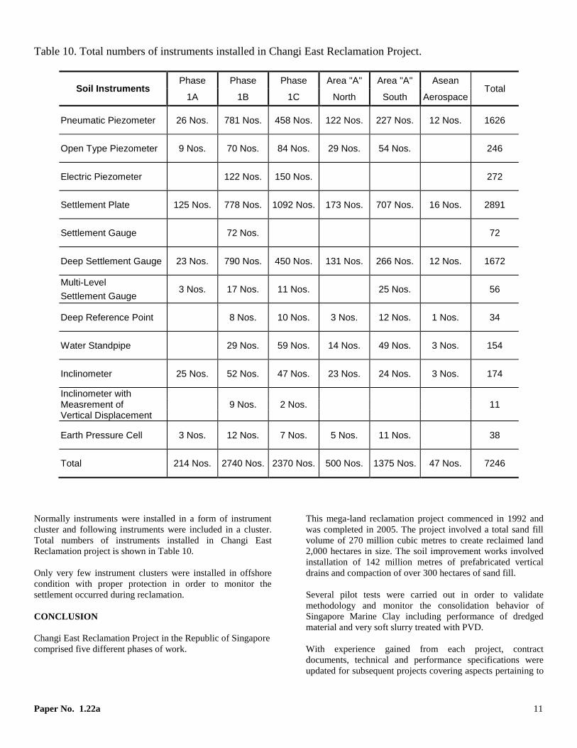
Table 10. Total numbers of instruments installed in Changi East Reclamation Project.
Soil Instruments Phase Phase Phase Area "A" Area "A" Asean
Total 1A 1B 1C North South Aerospace
Pneumatic Piezometer 26 Nos. 781 Nos. 458 Nos. 122 Nos. 227 Nos. 12 Nos. 1626
Open Type Piezometer 9 Nos. 70 Nos. 84 Nos. 29 Nos. 54 Nos. 246
Electric Piezometer 122 Nos. 150 Nos. 272
Settlement Plate 125 Nos. 778 Nos. 1092 Nos. 173 Nos. 707 Nos. 16 Nos. 2891
Settlement Gauge 72 Nos. 72
Deep Settlement Gauge 23 Nos. 790 Nos. 450 Nos. 131 Nos. 266 Nos. 12 Nos. 1672
Multi-Level 3 Nos. 17 Nos. 11 Nos. 25 Nos. 56
Settlement Gauge
Deep Reference Point 8 Nos. 10 Nos. 3 Nos. 12 Nos. 1 Nos. 34
Water Standpipe 29 Nos. 59 Nos. 14 Nos. 49 Nos. 3 Nos. 154
Inclinometer 25 Nos. 52 Nos. 47 Nos. 23 Nos. 24 Nos. 3 Nos. 174
Inclinometer with 9 Nos. 2 Nos. 11 Measrement of
Vertical Displacement
Earth Pressure Cell 3 Nos. 12 Nos. 7 Nos. 5 Nos. 11 Nos. 38
Total 214 Nos. 2740 Nos. 2370 Nos. 500 Nos. 1375 Nos. 47 Nos. 7246
Normally instruments were installed in a form of instrument
cluster and following instruments were included in a cluster.
Total numbers of instruments installed in Changi East
Reclamation project is shown in Table 10.
Only very few instrument clusters were installed in offshore
condition with proper protection in order to monitor the
settlement occurred during reclamation.
CONCLUSION
Changi East Reclamation Project in the Republic of Singapore
comprised five different phases of work.
This mega-land reclamation project commenced in 1992 and
was completed in 2005. The project involved a total sand fill
volume of 270 million cubic metres to create reclaimed land
2,000 hectares in size. The soil improvement works involved
installation of 142 million metres of prefabricated vertical
drains and compaction of over 300 hectares of sand fill.
Several pilot tests were carried out in order to validate
methodology and monitor the consolidation behavior of
Singapore Marine Clay including performance of dredged
material and very soft slurry treated with PVD.
With experience gained from each project, contract
documents, technical and performance specifications were
updated for subsequent projects covering aspects pertaining to
Paper No. 1.22a 12
dredging, reclamation and shore protection works, soil
improvement works on natural clay, dredged clay and ultra-
soft slurry using prefabricated vertical drain and densification
of granular fill by various deep compaction techniques.
REFERENCES
Arulrajah, A., Nikraz, H. and Bo, M.W. (2004a). “Factors
Affecting Field Instrumentation Assessment of Marine
Clay Treated With Prefabricated Vertical Drains”,
Geotextiles and Geomembranes, Elsevier, Vol. 22, No. 5,
October, pp. 415-437.
Arulrajah, A., Nikraz, H. and Bo, M.W. (2004b).
“Observational Methods of Assessing Improvement of
Marine Clay”, Proceedings of the Institution of Civil
Engineers (UK), Ground Improvement, Vol. 8, No. 4,
October, pp. 151-169.
Arulrajah, A., Nikraz, H. and M. W. Bo (2005). “In-Situ
Testing of Singapore Marine Clay at Changi”,
Geotechnical and Geological Engineering: an international
journal, Springer, Vol. 23, No. 2, pp. 111-130.
Arulrajah, A., Nikraz, H. and Bo, M.W. (2006). “Assessment
of Marine Clay Improvement under Reclamation Fills by
In-Situ Testing Methods”, Geotechnical and Geological
Engineering: an international journal, Springer, Volume
24, No. 1, pp. 219-226.
Arulrajah, A., Bo, M.W., Chu, J. and Nikraz, H. (2009).
“Instrumentation at the Changi Land Reclamation Project,
Singapore”, Proceedings of the Institution of Civil
Engineers (UK), Geotechnical Engineering, Vol. 162, no.1,
pp. 33-40.
Bo Myint Win, Arulrajah, A. and Choa, V. (1998),
“Instrumentation and Monitoring of Soil Improvement
Works in Land Reclamation”, 8th International IAEG
Congress 1998, Balkema, Rotterdam.
Bo Myint Win, Bawajee, R. and Choa, V. (1999a),
“Comparative Study on Performance of Vertical Drain”,
11th
Asia Regional Conference on Soil Mechanics and
Geotechnical Engineering, August 1999, Hong et al. (eds)
Balkema, Rotterdam, Seoul, Korea.
Bo Myint Win, Chu, J. and Choa, V. (1999b), “Factors
Affecting the Assessment of Degree of Consolidation”,
International Conference on Field Measurements in
Geomechanics, 1999, Leung, Tan and Phoon (eds),
Balkema, Rotterdam.
Bo Myint Win, Bawajee, R. and Choa, V. (2000),
“Implementation of Mega Soil Improvement Works”,
International Symposium on Coastal Geotechnical
Engineering in Practice, September 2000, Nakase &
Tsuchida (eds) © Balkema, Rotterdam, IS-Yokohama,
Japan.
Bo Myint Win and Choa, V. (2002), “Geotechnical
Instrumentation for Land Reclamation Projects” A
Conference on Case Studies in Geotechnical Engineering,
4 & 5 July 2002, Singapore.
Bo, M W. Chu,, J. Low, B K. & Choa, V (2003), “Soil
Improvement – Prefabricated Vertical Drain Techniques”
Thomson learning, Singapore.
Bo, M.W., Arulrajah, A., Na, Y.M & Chang, M.F. (2009) “A
case study on densification of soil by dynamic
compaction” Ground Improvement, Institution of Civil
Engineers UK, Volume 162, Issue GI3, August, pp. 121-
132.
Bo, M W. Chang, M.F. Arulrajah, A. & Choa, V. (2012),
“Ground Investigation for Changi East Reclamation
Projects” Geotechnical and Geological Engineering,
Springer, Vol.30, Issue 1, pp. 45-62.
Choa, V. (1994), “Application of the Observational Method to
Hydraulic Fill Reclamation Projects”, Geotechnique, 44,
No. 4, pp. 735-745.
Choa, V., Bo, M. W., Arulrajah, A. & Na, Y. M (1997):
“Overview of Densification of Granular Soil by Deep
Compaction Methods”, 1st International Conference on
Ground Improvement Techniques, May 1997, Macau.
Choa, V. and Bo Myint Win (2000), “Quality Assurance of
Prefabricated Vertical Drain in Changi East
Reclamation”, International Seminar of Geotechnics,
September 2000, Kochi, Japan.
Choa, V., Bo, M. W. and Chu, J. (2001), “Soil Improvement
Works for Changi East Reclamation Project”, Ground
Improvement (2001), Vol. 5, No. 4, pp. 141-153.
Choa, V. (2001), “Reclamation and Soil Improvement on
Ultra-soft Soil”, Symposium 2001 on Soft Ground
Improvement and Geosynthetic Applications, 22-23
November 2001, Bangkok, Thailand, pp. 1-20.
.