planning a drainage water management system...- 2 - figure 3: dwm planning involves determining...
TRANSCRIPT
Planning a Drainage Water Management System Jane R. Frankenberger, Purdue University and Gary R. Sands, University of Minnesota
WHAT IS DRAINAGE WATER MANAGEMENT?
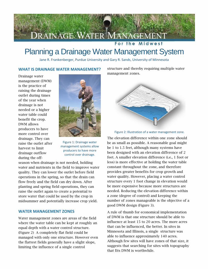
Drainage water
management (DWM)
is the practice of
raising the drainage
outlet during times
of the year when
drainage is not
needed or a higher
water table could
benefit the crop.
DWM allows
producers to have
more control over
drainage. They can
raise the outlet after
harvest to limit
drainage outflow
during the off-
season when drainage is not needed, holding
water and nutrients in the field to improve water
quality. They can lower the outlet before field
operations in the spring, so that the drain can
flow freely and the field can dry down. After
planting and spring field operations, they can
raise the outlet again to create a potential to
store water that could be used by the crop in
midsummer and potentially increase crop yield.
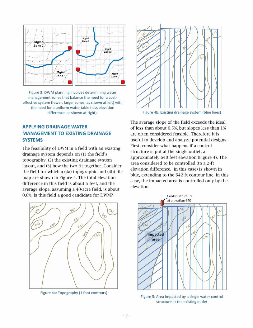
WATER MANAGEMENT ZONES
Water management zones are areas of the field
where the water table can be kept at roughly an
equal depth with a water control structure.
(Figure 2) A completely flat field could be
managed with only one structure. However even
the flattest fields generally have a slight slope,
limiting the influence of a single control
structure and thereby requiring multiple water
management zones.
Figure 2: Illustration of a water management zone.
The elevation difference within one zone should
be as small as possible. A reasonable goal might
be 1 to 1.5 feet, although many systems have
been designed with an elevation difference of 2
feet. A smaller elevation difference (i.e., 1 foot or
less) is more effective at holding the water table
constant throughout the zone, and therefore
provides greater benefits for crop growth and
water quality. However, placing a water control
structure every 1 foot change in elevation would
be more expensive because more structures are
needed. Reducing the elevation difference within
a zone (degree of control) and keeping the
number of zones manageable is the objective of a
good DWM design (Figure 3).
A rule of thumb for economical implementation
of DWM is that one structure should be able to
influence at least 15 to 20 acres. The more acres
that can be influenced, the better. In sites in
Minnesota and Illinois, a single structure was
able to influence approximately 140 acres.
Although few sites will have zones of that size, it
suggests that searching for sites with topography
that fits DWM is worthwhile.
Figure 1: Drainage water management systems allow
producers to have more control over drainage.
- 2 -
Figure 3: DWM planning involves determining water management zones that balance the need for a cost-
effective system (fewer, larger zones, as shown at left) with the need for a uniform water table (less elevation
difference, as shown at right).
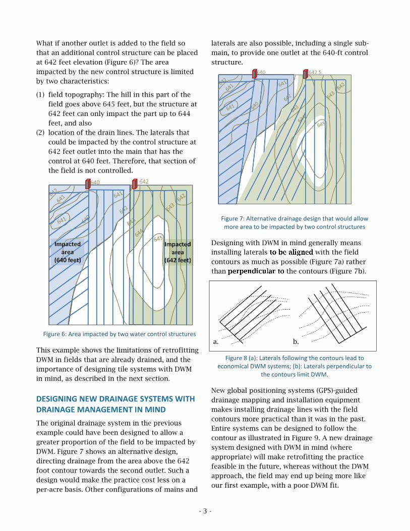
APPLYING DRAINAGE WATER MANAGEMENT TO EXISTING DRAINAGE SYSTEMS
The feasibility of DWM in a field with an existing
drainage system depends on (1) the field’s
topography, (2) the existing drainage system
layout, and (3) how the two fit together. Consider
the field for which a (4a) topographic and (4b) tile
map are shown in Figure 4. The total elevation
difference in this field is about 5 feet, and the
average slope, assuming a 40-acre field, is about
0.6%. Is this field a good candidate for DWM?
Figure 4a: Topography (1 foot contours)
Figure 4b: Existing drainage system (blue lines)
The average slope of the field exceeds the ideal
of less than about 0.5%, but slopes less than 1%
are often considered feasible. Therefore it is
useful to develop and analyze potential designs.
First, consider what happens if a control
structure is put at the single outlet, at
approximately 640 feet elevation (Figure 4). The
area considered to be controlled (to a 2-ft
elevation difference, in this case) is shown in
blue, extending to the 642-ft contour line. In this
case, the impacted area is controlled only by the
elevation.
Figure 5: Area impacted by a single water control structure at the existing outlet
- 3 -
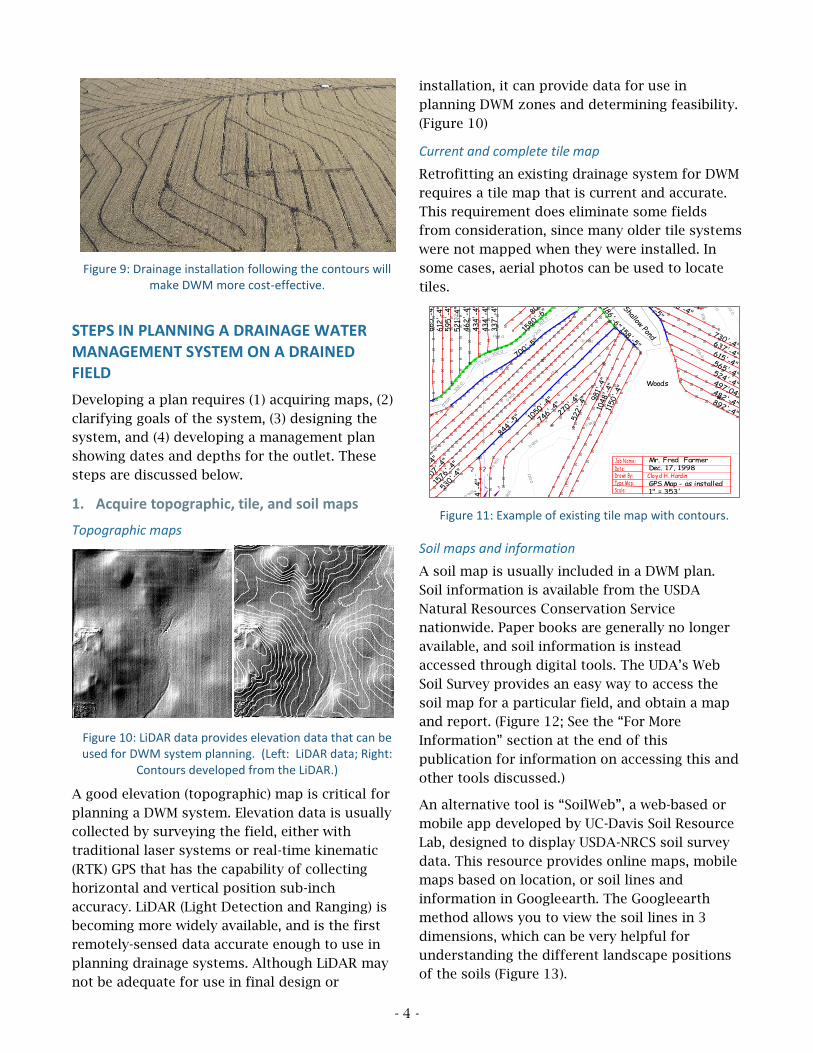
What if another outlet is added to the field so
that an additional control structure can be placed
at 642 feet elevation (Figure 6)? The area
impacted by the new control structure is limited
by two characteristics:
(1) field topography: The hill in this part of the
field goes above 645 feet, but the structure at
642 feet can only impact the part up to 644
feet, and also
(2) location of the drain lines. The laterals that
could be impacted by the control structure at
642 feet outlet into the main that has the
control at 640 feet. Therefore, that section of
the field is not controlled.
Figure 6: Area impacted by two water control structures
This example shows the limitations of retrofitting
DWM in fields that are already drained, and the
importance of designing tile systems with DWM
in mind, as described in the next section.
DESIGNING NEW DRAINAGE SYSTEMS WITH DRAINAGE MANAGEMENT IN MIND
The original drainage system in the previous
example could have been designed to allow a
greater proportion of the field to be impacted by
DWM. Figure 7 shows an alternative design,
directing drainage from the area above the 642
foot contour towards the second outlet. Such a
design would make the practice cost less on a
per-acre basis. Other configurations of mains and
laterals are also possible, including a single sub-
main, to provide one outlet at the 640-ft control
structure.
Figure 7: Alternative drainage design that would allow more area to be impacted by two control structures
Designing with DWM in mind generally means
installing laterals with the field
contours as much as possible (Figure 7a) rather
than the contours (Figure 7b).
a. b.
Figure 8 (a): Laterals following the contours lead to economical DWM systems; (b): Laterals perpendicular to
the contours limit DWM.
New global positioning systems (GPS)-guided
drainage mapping and installation equipment
makes installing drainage lines with the field
contours more practical than it was in the past.
Entire systems can be designed to follow the
contour as illustrated in Figure 9. A new drainage
system designed with DWM in mind (where
appropriate) will make retrofitting the practice
feasible in the future, whereas without the DWM
approach, the field may end up being more like
our first example, with a poor DWM fit.
- 4 -
Figure 9: Drainage installation following the contours will make DWM more cost-effective.
STEPS IN PLANNING A DRAINAGE WATER MANAGEMENT SYSTEM ON A DRAINED FIELD
Developing a plan requires (1) acquiring maps, (2)
clarifying goals of the system, (3) designing the
system, and (4) developing a management plan
showing dates and depths for the outlet. These
steps are discussed below.
1. Acquire topographic, tile, and soil maps
Topographic maps
Figure 10: LiDAR data provides elevation data that can be used for DWM system planning. (Left: LiDAR data; Right:
Contours developed from the LiDAR.)
A good elevation (topographic) map is critical for
planning a DWM system. Elevation data is usually
collected by surveying the field, either with
traditional laser systems or real-time kinematic
(RTK) GPS that has the capability of collecting
horizontal and vertical position sub-inch
accuracy. LiDAR (Light Detection and Ranging) is
becoming more widely available, and is the first
remotely-sensed data accurate enough to use in
planning drainage systems. Although LiDAR may
not be adequate for use in final design or
installation, it can provide data for use in
planning DWM zones and determining feasibility.
(Figure 10)
Current and complete tile map
Retrofitting an existing drainage system for DWM
requires a tile map that is current and accurate.
This requirement does eliminate some fields
from consideration, since many older tile systems
were not mapped when they were installed. In
some cases, aerial photos can be used to locate
tiles.
Figure 11: Example of existing tile map with contours.
Soil maps and information
A soil map is usually included in a DWM plan.
Soil information is available from the USDA
Natural Resources Conservation Service
nationwide. Paper books are generally no longer
available, and soil information is instead
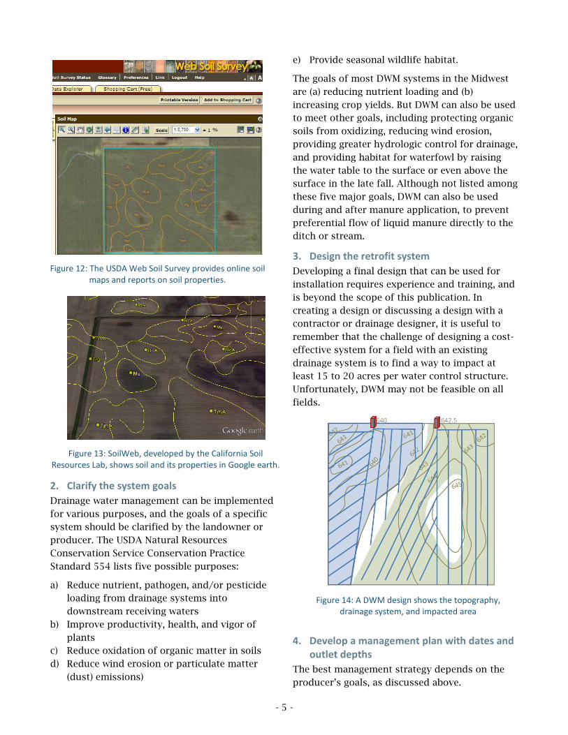
accessed through digital tools. The UDA’s Web
Soil Survey provides an easy way to access the
soil map for a particular field, and obtain a map
and report. (Figure 12; See the “For More
Information” section at the end of this
publication for information on accessing this and
other tools discussed.)
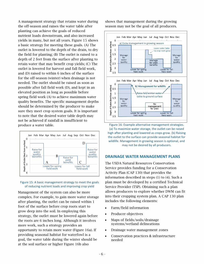
An alternative tool is “SoilWeb”, a web-based or
mobile app developed by UC-Davis Soil Resource
Lab, designed to display USDA-NRCS soil survey
data. This resource provides online maps, mobile
maps based on location, or soil lines and
information in Google earth. The Google earth
method allows you to view the soil lines in 3
dimensions, which can be very helpful for
understanding the different landscape positions
of the soils (Figure 13).
96.0
96.0
100.0
100.0
100.0
100.0
100.0
104.0
104.0
104.0
104.0
104.0
104.0
104.0
104.0
104.0
104
.0
104.0
104.0
104.0
104.0
104.0
104.0
104.0
104.0
104.0
108.0
108.0
108.0
108.0
108.0
108.0
108.0
108.0
108.0
108.0
112.0
112.0
112.0
112.0
112.0
112.0
116.0
116.0
116.0
120.0
124.0
98.0
98.0
102.0
102.0
102.
0
102
.0
102.0
102.0
102.
0
102.0
102.0
102.0
102.0
102.0
102.0
102.0
102.0
102.0
102.0
102.0
106.0
106.0
106.0
106.0
106.0
106.0
106.0
106.0
106.0
106.0
106
.0
106.0
106.0
106.0
106
.0
110.0
110.0
110.0
110.0
110.0
110.0
110.0
110.0
110.0
110.0
114.0
114.0
114.0
114.0
118.0
118.0
122.0
67
0'-
4"
68
5'-
4"
73
0'-
4"
75
3'-
4"
78
6'-
4"
78
3'-
4"
80
9'-
4"
82
7'-
4"
817
'-4
"8
22
'-4
"8
12'-
4"
73
4'-
4"
66
5'-
4"
612
'-4
"5
95
'-4
"5
21'
-4"
46
2'-
4"
43
4'-
4"
43
4'-
4"
33
7'-
4"
231'
-4"
255'-
4"
803'-
4"770'-
4"
1580'
-6"
399'-4"224'-4"
266'-5"
216'-4"
240'-
4"
431'
-4"
438'-
4"
531'-4
"
625'
-4"
754'
-4"
1121
'-4"
1526
'-4"
1650
'-4"
1707
'-4"
1576
'-4"
530'
-4"
844'
-5"
62
4'-
4"
1050'
-4"
746'-
4"27
0'-4"
522'
-4" 98
1'-4
"10
48'-
4"11
50'-
4"
186'-6"
892'-4"
482'-4"
497'04"
524'-4"
565'-4"
615'-4"
637'-4"
730'-4"
386'-4"
501'-4"
200'
68
6'-
8"
59
0'-
6"
372'-4"365'-4"369'-4"355'-4"330'-4"311'-4"271'-4"192'-4"
264'-4"
700'-5"
100'
-6"
Alt. Bench Mark: FlowLine of Concrete Culvert under US 150Local Coordinates:N-5394.18, E-3881.76, Elev-93.63
Mr. Fred FarmerDec. 17, 1998
GPS Map - as installed1" = 353'
Bench Mark:Top of existing concrete culvertunder US Hwy. 150Local Coordinates:Northing - 5000Easting - 5000Elevation - 100.00'
5" Orange Top Riser
US Hwy 150
158'-5"
4" Tubing w/ GPS point m arkers
5" Tubing w/ GPS point m arkers
6" Tubing w/ GPS point m arkers
Job Nam e:Dat e:Drawn By:Type Map:Scale:
Cloyd H. Hardin
Old or Exist ing Tile
Proposed Tubing
Open Dit ch or Drainage W ay
NORTH
GPS E lectronic Data andpoint coordinates are onfi le at H & H Drainage.
Global Pos it ioning Syst em Dat a Point
Open Ditch/ WaterWay
Prop
erty
Lin
e
Prop
ert
y L
ine Property Line
Shallow Pond
Woods
Property Line
Farm Lane
Contour Lines - 2 feet intervals
455'-5"
610'-4"
759'-
4"
-4"
Breather
71.3 acres surveyed, 43.9 acres drained. Soil Type- Bartle
Breather
? ?
Clay ended at Springs
Repaired 4/14/99
- 5 -
Figure 12: The USDA Web Soil Survey provides online soil maps and reports on soil properties.
Figure 13: SoilWeb, developed by the California Soil Resources Lab, shows soil and its properties in Google earth.
2. Clarify the system goals
Drainage water management can be implemented
for various purposes, and the goals of a specific
system should be clarified by the landowner or
producer. The USDA Natural Resources
Conservation Service Conservation Practice
Standard 554 lists five possible purposes:
a) Reduce nutrient, pathogen, and/or pesticide
loading from drainage systems into
downstream receiving waters
b) Improve productivity, health, and vigor of
plants
c) Reduce oxidation of organic matter in soils
d) Reduce wind erosion or particulate matter
(dust) emissions)
e) Provide seasonal wildlife habitat.
The goals of most DWM systems in the Midwest
are (a) reducing nutrient loading and (b)
increasing crop yields. But DWM can also be used
to meet other goals, including protecting organic
soils from oxidizing, reducing wind erosion,
providing greater hydrologic control for drainage,
and providing habitat for waterfowl by raising
the water table to the surface or even above the
surface in the late fall. Although not listed among
these five major goals, DWM can also be used
during and after manure application, to prevent
preferential flow of liquid manure directly to the
ditch or stream.
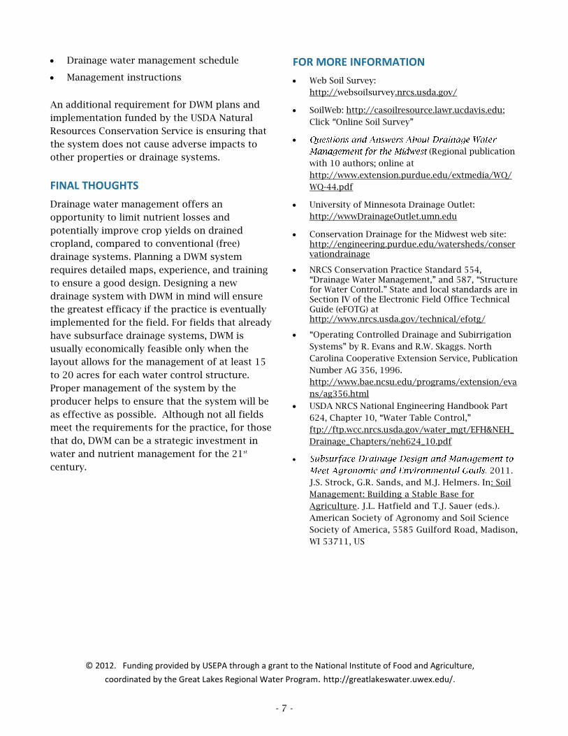
3. Design the retrofit system
Developing a final design that can be used for
installation requires experience and training, and
is beyond the scope of this publication. In
creating a design or discussing a design with a
contractor or drainage designer, it is useful to
remember that the challenge of designing a cost-
effective system for a field with an existing
drainage system is to find a way to impact at
least 15 to 20 acres per water control structure.
Unfortunately, DWM may not be feasible on all
fields.
Figure 14: A DWM design shows the topography, drainage system, and impacted area
4. Develop a management plan with dates and outlet depths
The best management strategy depends on the
producer’s goals, as discussed above.
- 6 -
A management strategy that retains water during
the off-season and raises the water table after
planting can achieve the goals of reduced
nutrient loads downstream, and also increased
yields in many, but not all years. Figure 15 shows
a basic strategy for meeting these goals. (A) The
outlet is lowered to the depth of the drain, to dry
the field for planting; (B) The outlet is raised to a
depth of 2 feet from the surface after planting to
retain water that may benefit crop yields; (C) The
outlet is lowered for harvest and fall field work,
and (D) raised to within 6 inches of the surface
for the off-season (winter) when drainage is not
needed. The outlet should be raised as soon as
possible after fall field work (D), and kept in an
elevated position as long as possible before
spring field work (A) to achieve maximum water
quality benefits. The specific management depths
should be determined by the producer to make
sure they meet crop system goals. It is important
to note that the desired water table depth may
not be achieved if rainfall is insufficient to
produce a water table.
Figure 15: A basic management strategy to meet the goals of reducing nutrient loads and improving crop yield
Management of the system can also be more
complex. For example, to gain more water storage
after planting, the outlet can be raised within 1
foot of the surface before crop roots start to
grow deep into the soil. In employing this
strategy, the outlet must be lowered again before
the roots are 6 inches long. Although it involves
more work, such a strategy provides an
opportunity to retain more water (Figure 16a). If
providing seasonal habitat for waterfowl is a
goal, the water table during the winter should be
at the soil surface or higher Figure 16b also
shows that management during the growing
season may not be the goal of all producers.
Figure 16: Example alternative management strategies. (a) To maximize water storage, the outlet can be raised
high after planting and lowered as crops grow. (b) Raising the outlet to the surface can provide seasonal habitat for wildlife. Management in growing season is optional, and
may not be desired by all producers.
DRAINAGE WATER MANAGEMENT PLANS
The USDA Natural Resources Conservation
Service provides funding for a Conservation
Activity Plan (CAP 130) that provides the
information described in steps (1) to (4). Such a
plan must be developed by a certified Technical
Service Provider (TSP). Obtaining such a plan
allows producers to explore whether DWM can fit
into their cropping system plan. A CAP 130 plan
includes the following elements:
Farm/field information
Producer objectives
Maps of fields/soils/drainage systems/wetland delineations
Drainage water management zones
Conservation practices & infrastructure needed
A
B
C
D
- 7 -
Drainage water management schedule
Management instructions
An additional requirement for DWM plans and
implementation funded by the USDA Natural
Resources Conservation Service is ensuring that
the system does not cause adverse impacts to
other properties or drainage systems.
FINAL THOUGHTS
Drainage water management offers an
opportunity to limit nutrient losses and
potentially improve crop yields on drained
cropland, compared to conventional (free)
drainage systems. Planning a DWM system
requires detailed maps, experience, and training
to ensure a good design. Designing a new
drainage system with DWM in mind will ensure
the greatest efficacy if the practice is eventually
implemented for the field. For fields that already
have subsurface drainage systems, DWM is
usually economically feasible only when the
layout allows for the management of at least 15
to 20 acres for each water control structure.
Proper management of the system by the
producer helps to ensure that the system will be
as effective as possible. Although not all fields
meet the requirements for the practice, for those
that do, DWM can be a strategic investment in
water and nutrient management for the 21st
century.
FOR MORE INFORMATION
Web Soil Survey:
http://websoilsurvey.nrcs.usda.gov/
SoilWeb: http://casoilresource.lawr.ucdavis.edu;
Click “Online Soil Survey”
(Regional publication
with 10 authors; online at
http://www.extension.purdue.edu/extmedia/WQ/
WQ-44.pdf
University of Minnesota Drainage Outlet:
http://wwwDrainageOutlet.umn.edu
Conservation Drainage for the Midwest web site: http://engineering.purdue.edu/watersheds/conservationdrainage
NRCS Conservation Practice Standard 554, “Drainage Water Management,” and 587, “Structure for Water Control.” State and local standards are in Section IV of the Electronic Field Office Technical Guide (eFOTG) at http://www.nrcs.usda.gov/technical/efotg/
“Operating Controlled Drainage and Subirrigation
Systems” by R. Evans and R.W. Skaggs. North
Carolina Cooperative Extension Service, Publication
Number AG 356, 1996.
http://www.bae.ncsu.edu/programs/extension/eva
ns/ag356.html
USDA NRCS National Engineering Handbook Part
624, Chapter 10, “Water Table Control,”
ftp://ftp.wcc.nrcs.usda.gov/water_mgt/EFH&NEH_
Drainage_Chapters/neh624_10.pdf
2011.
J.S. Strock, G.R. Sands, and M.J. Helmers. In: Soil
Management: Building a Stable Base for
Agriculture. J.L. Hatfield and T.J. Sauer (eds.).
American Society of Agronomy and Soil Science
Society of America, 5585 Guilford Road, Madison,
WI 53711, US
© 2012. Funding provided by USEPA through a grant to the National Institute of Food and Agriculture,
coordinated by the Great Lakes Regional Water Program. http://greatlakeswater.uwex.edu/.