planetary rover developments supporting mars … · · 2013-03-28planetary rover developments...
TRANSCRIPT

Autonomous Robots 14, 103–126, 2003c© 2003 Kluwer Academic Publishers. Manufactured in The Netherlands.
Planetary Rover Developments Supporting Mars Exploration,Sample Return and Future Human-Robotic Colonization
PAUL S. SCHENKER, TERRY L. HUNTSBERGER, PAOLO PIRJANIAN, ERIC T. BAUMGARTNERAND EDDIE TUNSTEL
Jet Propulsion Laboratory, 4800 Oak Grove Drive, Pasadena, CA 91109, [email protected]
Abstract. We overview our recent research on planetary mobility. Products of this effort include the Field Inte-grated Design & Operations rover (FIDO), Sample Return Rover (SRR), reconfigurable rover units that function asan All Terrain Explorer (ATE), and a multi-Robot Work Crew of closely cooperating rovers (RWC). FIDO roveris an advanced technology prototype; its design and field testing support NASA’s development of long range, insitu Mars surface science missions. Complementing this, SRR implements autonomous visual recognition, nav-igation, rendezvous, and manipulation functions enabling small object pick-up, handling, and precision terminaldocking to a Mars ascent vehicle for future Mars Sample Return. ATE implements on-board reconfiguration ofrover geometry and control for adaptive response to adverse and changing terrain, e.g., traversal of steep, sandyslopes. RWC implements coordinated control of two rovers under closed loop kinematics and force constraints,e.g., transport of large payloads, as would occur in robotic colonies at future Mars outposts. RWC is based ina new extensible architecture for decentralized control of, and collective state estimation by multiple heteroge-neous robotic platforms—CAMPOUT; we overview the key architectural features. We have conducted experimentswith all these new rover system concepts over variable natural terrain. For each of the above developments, wesummarize our approach, some of our key experimental results to date, and our future directions of planneddevelopment.
Keywords: mobile robots, cooperating robots, all terrain mobility, robotic colonies, robot architecture, reconfig-urable robots
1. Introduction
There is growing international interest in wide-rangingexploration of the Martian surface. A better understand-ing of Mars’ surface geology, morphology, geochem-istry, and atmospheric science will yield importantinsights about comparative planetary origins, poten-tial for past/present life, and capabilities of the Marssurface environment to sustain a permanent human-robotic colonized presence.
Thus, institutions worldwide are pursuing devel-opment of Mars mission platforms/payloads, bothfixed and mobile, toward these science objectives.There are many options for such Mars surface ex-ploration: stationary landers with affixed instruments/
samplers, gravity-impact penetrators, shallow anddeep drills, subsurface/tethered “moles”, light air-planes, touch-and-go atmospheric balloons, and semi-autonomous surface mobility. The word “semi”connotes earth-based planning, command-sequencingand analysis of rover activity sequences and dataproducts—as done by a science-engineering teamthrough periodic data down-link and command up-links. We have done past related work on dexterouslanded manipulators (Schenker et al., 1995, 1999a) re-sulting in a concept for NASA’s Mars Polar Landermission of 1998. More recently we have focused ondeveloping mobile science platforms—science rovers,such as the FIDO technology prototype shown inFig. 1.
104 Schenker et al.
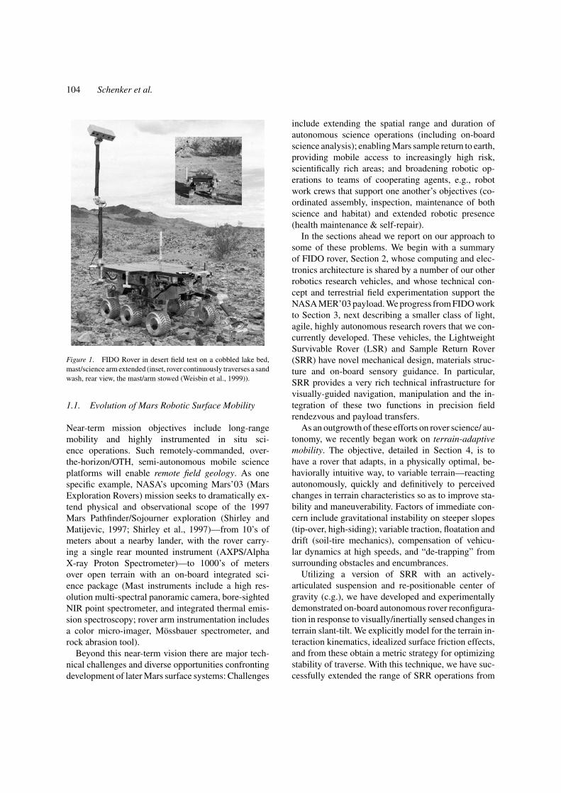
Figure 1. FIDO Rover in desert field test on a cobbled lake bed,mast/science arm extended (inset, rover continuously traverses a sandwash, rear view, the mast/arm stowed (Weisbin et al., 1999)).
1.1. Evolution of Mars Robotic Surface Mobility
Near-term mission objectives include long-rangemobility and highly instrumented in situ sci-ence operations. Such remotely-commanded, over-the-horizon/OTH, semi-autonomous mobile scienceplatforms will enable remote field geology. As onespecific example, NASA’s upcoming Mars’03 (MarsExploration Rovers) mission seeks to dramatically ex-tend physical and observational scope of the 1997Mars Pathfinder/Sojourner exploration (Shirley andMatijevic, 1997; Shirley et al., 1997)—from 10’s ofmeters about a nearby lander, with the rover carry-ing a single rear mounted instrument (AXPS/AlphaX-ray Proton Spectrometer)—to 1000’s of metersover open terrain with an on-board integrated sci-ence package (Mast instruments include a high res-olution multi-spectral panoramic camera, bore-sightedNIR point spectrometer, and integrated thermal emis-sion spectroscopy; rover arm instrumentation includesa color micro-imager, Mossbauer spectrometer, androck abrasion tool).
Beyond this near-term vision there are major tech-nical challenges and diverse opportunities confrontingdevelopment of later Mars surface systems: Challenges
include extending the spatial range and duration ofautonomous science operations (including on-boardscience analysis); enabling Mars sample return to earth,providing mobile access to increasingly high risk,scientifically rich areas; and broadening robotic op-erations to teams of cooperating agents, e.g., robotwork crews that support one another’s objectives (co-ordinated assembly, inspection, maintenance of bothscience and habitat) and extended robotic presence(health maintenance & self-repair).
In the sections ahead we report on our approach tosome of these problems. We begin with a summaryof FIDO rover, Section 2, whose computing and elec-tronics architecture is shared by a number of our otherrobotics research vehicles, and whose technical con-cept and terrestrial field experimentation support theNASA MER’03 payload. We progress from FIDO workto Section 3, next describing a smaller class of light,agile, highly autonomous research rovers that we con-currently developed. These vehicles, the LightweightSurvivable Rover (LSR) and Sample Return Rover(SRR) have novel mechanical design, materials struc-ture and on-board sensory guidance. In particular,SRR provides a very rich technical infrastructure forvisually-guided navigation, manipulation and the in-tegration of these two functions in precision fieldrendezvous and payload transfers.
As an outgrowth of these efforts on rover science/ au-tonomy, we recently began work on terrain-adaptivemobility. The objective, detailed in Section 4, is tohave a rover that adapts, in a physically optimal, be-haviorally intuitive way, to variable terrain—reactingautonomously, quickly and definitively to perceivedchanges in terrain characteristics so as to improve sta-bility and maneuverability. Factors of immediate con-cern include gravitational instability on steeper slopes(tip-over, high-siding); variable traction, floatation anddrift (soil-tire mechanics), compensation of vehicu-lar dynamics at high speeds, and “de-trapping” fromsurrounding obstacles and encumbrances.
Utilizing a version of SRR with an actively-articulated suspension and re-positionable center ofgravity (c.g.), we have developed and experimentallydemonstrated on-board autonomous rover reconfigura-tion in response to visually/inertially sensed changes interrain slant-tilt. We explicitly model for the terrain in-teraction kinematics, idealized surface friction effects,and from these obtain a metric strategy for optimizingstability of traverse. With this technique, we have suc-cessfully extended the range of SRR operations from

Planetary Rover Developments 105
12-to-15 degree slopes (given a fixed suspension ge-ometry) to 40-to-50 degrees (variable shoulder strutangles and c.g. offset by repositioning of attached ma-nipulator). Beyond this initial effort, our work pro-gresses toward “reconfigurable mobility”: a rover, orcollective robotic modules at higher levels of granu-larity, that can autonomously restructure their overallelectro-mechanical and sensor-based control organiza-tion in optimal response to environmental and internalsystem states.
Following this, in Section 5, we next discuss a newrobotics architecture—CAMPOUT (Control Architec-ture for Multi-Robot Planetary Outposts)—for closelycoordinated operations of two or more mobile robotsoperating under tight kinematics and force constraints.CAMPOUT utilizes hierarchically layered and col-lective behaviors to enable efficient distributed sens-ing, communications, and control among an extensi-ble set of robots. We have implemented preliminarydemonstrations of CAMPOUT on two SRR-derivedplatforms, with experiments on the coordinated ma-nipulation and transport of large payloads and coor-dinated access to areas of terrain slope in excess of60-to-70 degrees.
2. Rovers for in situ Science Exploration
There is a relatively well-established art for au-tonomous terrestrial mobile robots, to much lesserdegree, robots for remote planetary surface science(Weisbin et al., 1999; Volpe et al., 2000). Variousconceptual prototypes are under development andfield testing at institutions worldwide (e.g., CMU andNASA/JPL in the US, CNES and CNRS in France,NASDA/MITI in Japan et al.). As noted above, NASAhas planned a related Mars mission for 2003 whereintwo such planetary rovers, operating independently,will carry out investigations of surface geology, miner-alogy, atmospheric and biological features. Toward thisend and NASA missions beyond, our group is develop-ing the Field Integrated Design & Operations (FIDO)rover (Schenker et al., 2001).
FIDO is a technology integration and mission op-erations testbed for semi-autonomous in situ scienceexploration. The general operational paradigm for thisclass of rover is as follows: Based on down-linkpanoramic imagery, as obtained from a rover-mountedcamera, scientists will designate nearby target(s) of in-terest to which the rover navigates via intermediateway-points. These are panorama coordinate locations
referenced to the world frame, possibly situated on fea-tures recognizable by on-board sensing (which takentogether constitute part of the sequence planning). Therover visually detects and avoids local obstacles, whilealso updating its absolute trajectory coordinates. Local-ization over longer distances is confirmed by groundanalysis—comparing the actual latest rover imagerywith views expected based on estimated position, asderived from onboard sensing.
In the particular case of FIDO, remote command andcontrol is implemented with WITS (Web Interface forTeleScience), a JPL-developed toolset for cooperative,geographically distributed Mars robotic science oper-ations (Backes et al., 1999). WITS (example shown inFig. 2) provides resources for science planning, 3D pre-and post-visualization of sequences, uplink command-telemetry, science & engineering data product down-link display and more. See also http://wits.jpl.nasa.gov.
Table 1 lists FIDO’s major design features. FIDOcapabilities include wide-area panoramic imaging (amast-mounted color stereo pair), 3D terrain mappingand hazard avoidance (B/W stereo navigation cameraon mast; chassis-mounted front/rear stereo), visual self-localization (visual map registration/tracking), local
Table 1. FIDO rover system features; for more detailed informationon the various rover subsystems, see the JPL FIDO public web sitehttp://fido.jpl.nasa.gov.
Mobility and manipulation• 6-wheel rocker-bogie, all wheels independently driven/steered• Max speed 9 cm/sec, 20 cm wheels, ground clearance 23 cm• Multiple mobility modes (turn-in place, “crab”, passive/active
wheel drive); max obstacle clearance ∼1.5 wheel diameters• Rover dimensions, 1.0 m (L) × 0.8 m (W) × 0.5 m (H);
68 kg mass• 4 d.o.f. articulated mast with integral science instrumentation• 4 d.o.f. fully actuated and instrumented front science arm
Navigation and control• PC104+, 266 MHz Intel Pentium, PCI/ISA bus, 64 MB RAM• ANSI C software architecture under V×Works 5.3 real-time OS• Front/rear hazard avoidance stereo camera pairs (115◦ H-FOV)• Mast-mounted navigation stereo camera pair (43◦ H-FOV)• Inertial measurement unit (IMU) and CCD-based sun sensor• Differential GPS for ground-truth reference of traverse
Science instrumentation• Mast-mounted multi-spectral stereo camera pair (650, 740,
855 nm, 10◦ FOV, .34 mrad IFOV); full extent is 1.94 m• Mast-mounted near-infrared point spectrometer (1.3–2.5 microns,
9.3 mrad projective field of view)• Arm-mounted color micro-imager (RGB color, 512 × 496 pixel,
1.5 × 1.5 cm2 FOV at approx. 3 mm standoff), and Mossbauerspectrometer; arm reach is ∼50+ cm)
• Rover-mounted Mini-Corer with belly stereo camera

106 Schenker et al.
Figure 2. Web Interface for Telescience (WITS) display as seen by a single operator at a PC/Unix-based workstation.
path planning (via area stereo/navcam maps), inertialand celestial navigaitional reference (accelerometers,gyros, and sun sensor), and finally, fused state estima-tion supporting long range navigation (viz., statisticalintegration of odometry, visual, inertial, sun sensor andother data sources via Extended Kalman Filtering andrelated techniques (Hoffman et al., 1999; Baumgartneret al., 2000)).
We are characterizing FIDO—the rover design atlarge; underlying sensing, control, sampling technolo-gies; and remote science operational strategies—in anincreasingly challenging set of science field trials un-der direction of NASA’s MER’03 flight science team(PI Steven Squyres, Cornell University, co-I RaymondArvidson, Washington University). A first trial at SilverLake, California, in the Mojave desert (1999) demon-strated a full “local sampling loop” about a putativelander site: panoramic imaging from the lander area,3D navigational mapping to ground-designated tar-
gets of interest, open-loop traverses to selected targets,bore-sighted IPS imaging of targets in both stand-offscanning and proximity pointing modes, kinematics-referenced 3D visualization and placement of mast/arminstruments and tools, targeting and extraction of rocksamples, and return to the immediate area of the lander.
A sequel field trial in spring 2000 at Black RockSummit, Nevada, added significant elements of missionrealism and complexity. In particular, operations wereblind and fully remote. The science team controlled therover by satellite communications from JPL; their priorsite information was limited to large area thematic anddescent imagery typical of real Mars orbital observa-tions. This trial was followed by another in spring 2001in the Soda Mountains of the Mojave Desert in Califor-nia, in which the resource and time constraints of theMER mission were explicitly included in the commandsequencing and data downlink activities. The MER sci-ence team with the MER mission operations personnel

Planetary Rover Developments 107
ran a 20-sol emulation that serves as direct training forthe upcoming mission.
The first action of the Science Operations Work-ing Group (SOWG) stationed at JPL was to acquirea full panorama looking out ∼50-to-100 meters andcorrelate this extensive visual data set with the multi-source overhead thematic visible and infrared imagery(incl. LANDSAT7+, TIMS, calibrated AVIRIS, typi-cally at 10-to-30 meters2 per pixel resolution; availabledata also included uncalibrated aerial photographs, per-spective views, etc.). Once so “situated,” the SOWGperformed a prospective analysis of nearby targets ofopportunity, ranking their science values against hy-potheses about geological and mineralogical structure.Some targets were close enough to allow an immediatenear-IR analysis via pointing of the mast-mounted IPS.This work done, the SOWG picked primary targets andcommanded rover approaches.
The terrain, as shown in Fig. 3, was quite challeng-ing and rich. This motivated a very “opportunistic” in-cremental exploration, in which the investigators fre-quently stopped the rover, deploying its arm-mountedmicro-imager to examine ground soils and rocks enroute to a primary target. A sense of the overall activityis depicted in Fig. 3, the rover having already acquiredand down-linked a panorama, now beginning its localscience in near field of the 1:1 scale lander mock-up.
Figure 3. FIDO Rover at the Nevada blind field test, egress from lander complete, and beginning its science mission. Pictures at upper andlower right: composite LANDSAT data and LANDSAT overlay of 3D TIMS reconstruction. See also http://wufs.wustl.edu/fido and examples,Fig. 4.
In the aggregate, this simulated Mars in situ scienceusing FIDO rover was akin to terrestrial field geology(Arvidson et al., 2000, 2001)—a nonlinear process ofscientific discovery and discernment wherein multiplehypotheses were incrementally formed based on ini-tial data and area history, then progressively updated,refuted or confirmed, with at times the overall inves-tigation being redirected as a new observation of yethigher perceived priority was made (example of dataproducts shown in Fig. 4). The SOWG, science in-vestigators and engineering/operations staff learned agreat deal in this multi-week experiment. Insights weregained about: (1) preferred science operational strate-gies and command-data sequencing protocols underrealistic time and bandwidth constraints; (2) limita-tions and impacts of open loop localization of the roverand instrument arm placement during target acquisition(processes involving coordination of rover motion withinverse kinematics positioning of arm-mounted instru-ments, also, positioning of a rover-mounted mini-corer,wrt. terrain maps derived from hazcam-bellycam-navcam); and (3) continuing directions of developmentfor 3D visualization (supporting rover activity plan-ning and instrument operations), resource modelsfor sequence planning (time, power, data volume,etc.), command-dictionary structure, downlink teleme-try processing, and finally, automated report generation
108 Schenker et al.
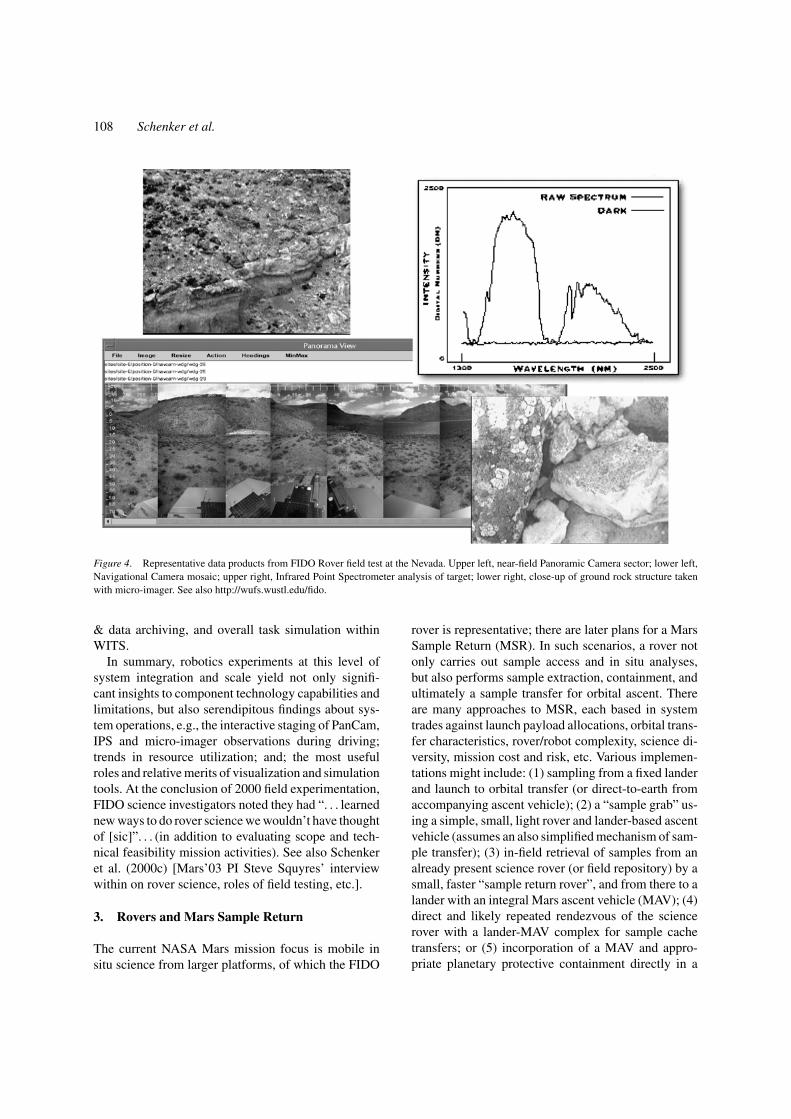
Figure 4. Representative data products from FIDO Rover field test at the Nevada. Upper left, near-field Panoramic Camera sector; lower left,Navigational Camera mosaic; upper right, Infrared Point Spectrometer analysis of target; lower right, close-up of ground rock structure takenwith micro-imager. See also http://wufs.wustl.edu/fido.
& data archiving, and overall task simulation withinWITS.
In summary, robotics experiments at this level ofsystem integration and scale yield not only signifi-cant insights to component technology capabilities andlimitations, but also serendipitous findings about sys-tem operations, e.g., the interactive staging of PanCam,IPS and micro-imager observations during driving;trends in resource utilization; and; the most usefulroles and relative merits of visualization and simulationtools. At the conclusion of 2000 field experimentation,FIDO science investigators noted they had “. . . learnednew ways to do rover science we wouldn’t have thoughtof [sic]”. . . (in addition to evaluating scope and tech-nical feasibility mission activities). See also Schenkeret al. (2000c) [Mars’03 PI Steve Squyres’ interviewwithin on rover science, roles of field testing, etc.].
3. Rovers and Mars Sample Return
The current NASA Mars mission focus is mobile insitu science from larger platforms, of which the FIDO
rover is representative; there are later plans for a MarsSample Return (MSR). In such scenarios, a rover notonly carries out sample access and in situ analyses,but also performs sample extraction, containment, andultimately a sample transfer for orbital ascent. Thereare many approaches to MSR, each based in systemtrades against launch payload allocations, orbital trans-fer characteristics, rover/robot complexity, science di-versity, mission cost and risk, etc. Various implemen-tations might include: (1) sampling from a fixed landerand launch to orbital transfer (or direct-to-earth fromaccompanying ascent vehicle); (2) a “sample grab” us-ing a simple, small, light rover and lander-based ascentvehicle (assumes an also simplified mechanism of sam-ple transfer); (3) in-field retrieval of samples from analready present science rover (or field repository) by asmall, faster “sample return rover”, and from there to alander with an integral Mars ascent vehicle (MAV); (4)direct and likely repeated rendezvous of the sciencerover with a lander-MAV complex for sample cachetransfers; or (5) incorporation of a MAV and appro-priate planetary protective containment directly in a
Planetary Rover Developments 109
large science rover. Several of these scenarios, partic-ularly (3) and (4), pose significant robotics challengesin the area of precision autonomous visual terminalguidance/servoing.
In recent years we have developed a class of light,fast, agile, small, and volume-efficient planetary roverdesigns that have attractive properties for Mars sur-face missions such as those described above. Theserobots are research prototypes. They are less maturethan the FIDO rover, indeed in some cases are thesources of algorithms, computing architecture, and me-chanical designs that continue to be frequently mi-grated to FIDO, and from there to flight. These newresearch vehicles have been operated in fairly realis-tic terrestrial scenarios, e.g., variable outdoor terrain,and stand-alone continuous driving sequence simula-tions of conceptual mission models and functions. Therovers are highly autonomous, can traverse surpris-ingly rugged terrain (Viking Lander 1/VL1 densities orgreater), and carry robot arms that can be autonomouslysequenced and visually servoed for instrument deploy-ment, sample cache pickup, and payload transfers. Thepotential range of applications for these 5-to-10 kg,20+ cm/sec instrumented rovers, used individually, orin cooperative multi-robot activities (later reported)is broad: local area, lander–based operations; mid-range over-the-horizon (OTH) science, precursor scoutmissions, sample cache rendezvous and retrieval, net-worked science, human-robot interactive field activi-ties/support (astronaut’s “tag-along”), and tightly co-ordinated multi-rover Mars outpost operations.
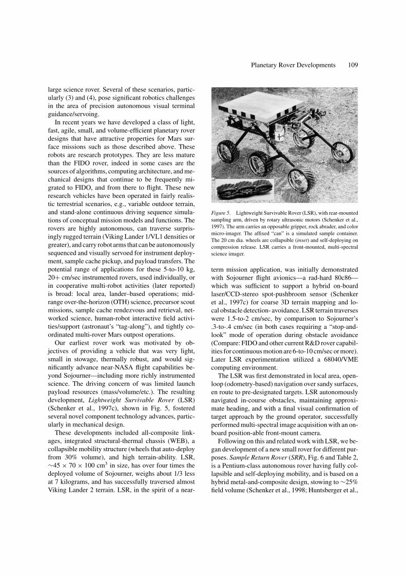
Our earliest rover work was motivated by ob-jectives of providing a vehicle that was very light,small in stowage, thermally robust, and would sig-nificantly advance near-NASA flight capabilities be-yond Sojourner—including more richly instrumentedscience. The driving concern of was limited launchpayload resources (mass/volume/etc.). The resultingdevelopment, Lightweight Survivable Rover (LSR)(Schenker et al., 1997c), shown in Fig. 5, fosteredseveral novel component technology advances, partic-ularly in mechanical design.
These developments included all-composite link-ages, integrated structural-thermal chassis (WEB), acollapsible mobility structure (wheels that auto-deployfrom 30% volume), and high terrain-ability. LSR,∼45 × 70 × 100 cm3 in size, has over four times thedeployed volume of Sojourner, weighs about 1/3 lessat 7 kilograms, and has successfully traversed almostViking Lander 2 terrain. LSR, in the spirit of a near-
Figure 5. Lightweight Survivable Rover (LSR), with rear-mountedsampling arm, driven by rotary ultrasonic motors (Schenker et al.,1997). The arm carries an opposable gripper, rock abrader, and colormicro-imager. The affixed “can” is a simulated sample container.The 20 cm dia. wheels are collapsible (inset) and self-deploying oncompression release. LSR carries a front-mounted, multi-spectralscience imager.
term mission application, was initially demonstratedwith Sojourner flight avionics—a rad-hard 80c86—which was sufficient to support a hybrid on-boardlaser/CCD-stereo spot-pushbroom sensor (Schenkeret al., 1997c) for coarse 3D terrain mapping and lo-cal obstacle detection- avoidance. LSR terrain traverseswere 1.5-to-2 cm/sec, by comparison to Sojourner’s.3-to-.4 cm/sec (in both cases requiring a “stop-and-look” mode of operation during obstacle avoidance(Compare: FIDO and other current R&D rover capabil-ities for continuous motion are 6-to-10 cm/sec or more).Later LSR experimentation utilized a 68040/VMEcomputing environment.
The LSR was first demonstrated in local area, open-loop (odometry-based) navigation over sandy surfaces,en route to pre-designated targets. LSR autonomouslynavigated in-course obstacles, maintaining approxi-mate heading, and with a final visual confirmation oftarget approach by the ground operator, successfullyperformed multi-spectral image acquisition with an on-board position-able front-mount camera.
Following on this and related work with LSR, we be-gan development of a new small rover for different pur-poses. Sample Return Rover (SRR), Fig. 6 and Table 2,is a Pentium-class autonomous rover having fully col-lapsible and self-deploying mobility, and is based on ahybrid metal-and-composite design, stowing to ∼25%field volume (Schenker et al., 1998; Huntsberger et al.,

110 Schenker et al.
Figure 6. Rover-to-rover rendezvous, sample cache retrieval in early SRR field testing at Arroyo Seco near JPL.
1999a). SRR when deployed is ∼35 × 55 × 85 cm3
and 9 kg and also has a capability to independentlyset its two shoulder strut angles via an internal activedifferential, e.g. to alter undercarriage obstacle clear-ance and and/or vehicle stance and weight distribution.SRR carries a very novel all-composite 70 cm robotarm (Schenker et al., 1997a), the end-point position-ing of which (for science instrument placement andobject or cache retrieval) is automatically controlledby on-board visually-servo functions, including somecapabilities for autonomous detection of objects of in-
terest. In Fig. 6, SRR is seen performing the final phasesof a simulated semi-autonomous “in-field” Mars ren-dezvous and sample cache retrieval. LSR is acting as thetarget “science rover”, and is being approached from adistance of about 20 meters. SRR invokes a series ofvisual goal detection, navigation, terminal guidance,3D object recognition-and-localization, and arm-servofunctions for closed-loop control of both rover posi-tioning and mobile manipulation (Huntsberger et al.,1999a). We have also implemented a similar longerrange scenario from 100+ meters wherein a RF beacon

Planetary Rover Developments 111
Table 2. Summary of SRR design features; see Schenker et al.(1998) and Huntsberger et al. (1999a) for detailed information onthe various rover subsystems and experimentation.
Mobility and configuration control• 4 wheel independent steering, fully instrumented, 3 N-m
& 3 rad/sec; 20 cm dia. encoded wheels, 19 N-m & 21 cm/sec• Passive, instrumented, rocker-type suspension with
active spur-gear differential articulated shoulder joint• Parallel linkage on suspension enables simultaneous operation
of articulated shoulder/passive rocker/steering
Manipulation and effectors• Fully instrumented 4 DOF (pitch, roll, yaw, lateral translation)
gimbal with compliant gripper for extended payload• Alternatively, 4 DOF instrument arm (MicroArms 1, 2) with
end-arm opposable grippe for sample acquisition/cache transfer
Computing and electronics• Pentium 266 MHz/32 MB, V × Works 5.4 RTOS, Solid State
Disk; Ethernet (1.5 Mb/s) wireless modem; 24 v batt.pack/1.0–1.5 hr.
• 2 × 4-axis mot-ctrl., 2 × 640 × 480 color frame-grab,12 bit × 16 ch D/A
• Front mounted stereo b/w pair, 120◦ FOV for hazard avoidance• Arm-mounted color pair 45◦ FOV for “mast” observations• Arm-mounted 20◦ b/w FOV elbow camera for goal tracking
initially guides SRR inward to the target rover. Anumber of important functions flowed out from thiswork, per illustration below, and were further inte-grated/developed in JPL rover activities to next bedescribed. These functions included: fused state esti-mation for high accuracy rover position-and-pose de-termination, wavelet-based visual detection of man-made objects and features, 3D visual registration withan observed dense feature set (for relative localizationof the two rovers), computationally efficient, means ofrobot arm visual end-point positioning with minimalpre-calibration (cache pick-up, instrument placements,etc.). The collage of Fig. 7 shows LSR and SRR invarious related activities, focusing visually guided de-tection/guidance/rendezvous.
More recent development of the SRR conceptfocused on its extension to rover-to-lander terminalrendezvous over significant distances, at high levelsof on-board autonomy. This work culminated in ademonstration of SRR that, like the last given exam-ple of rover-to-rover rendezvous, was conducted in theArroyo Seco near JPL, Pasadena, CA. By compari-son, the scope, complexity, and continuity of opera-tions in Fig. 8 were somewhat greater than in Fig. 6.This work involved autonomously detecting a Mars’03replica lander geometry from over 125 meters, trackingto a mid-range of 20+meters, visually acquiring a more
detailed multi-point map of lander locations of interest,approaching closely (several meters), then developinga very accurate and robust fused feature map of lan-der structure, moving into closure of a meter or less,with final registration of SRR to within 1-to-3 cm and1-to-2 degrees accuracy at the lander ramp entry point.This was all done under sequentially staged autonomy,starting from fairly arbitrary approach directions.
This integrated operational capability is obvi-ously important for MSR-type missions, as it im-plies great time efficiency in sample return legs forMAV transfer and launch (as opposed to nominalmulti-day uplink-downlink cycles). Further, note thatthe two just described precision terminal rendezvousparadigms—including visual manipulation from mo-bile platforms—will be generic to rover-to-rover androver-to-lander/habitat surface operations across manyscience, servicing, and human-robot outpost scenarios.
4. Rovers and High Risk Access Operations
The logical and desired evolution of science roverswould be to more all-terrain capabilities. There are nu-merous known and posited areas of the Mars surfacethat are not currently within safe reach of conventionalrover designs, yet promise to be high in science content.For example, there have been recent orbital observa-tions suggesting water out-flows and extended regionsof rich mineralogy near cliff edges. Thus, developmentof mechanization and control architectures that enableroving into adverse, challenging terrain—areas chang-ing markedly over short distances—is of considerableimportance. Such developments of course also haveterrestrial applications (military, rescue, etc.).
We have recently conducted related R&D basedaround SRR, with emphasis on having the roverautonomously adapt its real time control behaviorsand configuration to observed/estimated terrain con-ditions and internal state. Figure 9 reflects one direc-tion we have undertaken in our supporting research.The general philosophy is to have the rover imageits forward-looking terrain, build a 3D local map,analyze traversability characteristics relative to kine-matics/quasistatics based maneuverability-stability ofprogress, and enact an appropriate behavior to opti-mize a rover performance index. The behavior is im-plemented on SRR in terms of reposing its stance andc.g. This is done in two ways: by independent artic-ulation of the rover shoulder strut angles, and reposi-tioning of the rover top-mounted robot arm. Per Fig. 9,

112 Schenker et al.
Figure 7. Starting from lower left, the SRR (cache retrieval rover) in near-field approach to LSR (science rover) and mid-field obstacleavoidance; Mars ascent vehicle (MAV) depiction; wavelet-based image localization of LSR from SRR goal camera; terminal goal-cameraguidance and staging for normal vector approach; eigenvector-based recognition/localization of cache; 3D feature set of LSR used in finalapproach 3D registration/localization; rover experiment on fused visual tracking/odometry navigation; and bottom center, derived 3D map forhazard avoidance. In the middle, visually referenced sample cache pick-up.
the arm is treated as a “reconfigurable resource” to beused in both kinematically unconstrained and closed-loop fashions, e.g., in the latter case, as another driveactuator, pivot point, or other causal element in rover-ground interactions. No consideration is yet given torover dynamics, as this is not a major contributory fac-tor in the 5-to-10 cm/sec regime and low mass/volumeenvelope we are treating. We do account, however, inconjunction with both thin and super-quadric surfacecontact models, for static friction and slip effects. Wediscuss this at length in Schenker et al. (2000b) andreferences therein, including details of the terrain stateestimation. Figure 10 sketches a related experimentalinfrastructure that we have developed.
In summary, our interest is in predicting the futurestate of the rover based upon look-ahead stereo rangeimaging, on-board IMU, and any other derived stateinformation that can be sensed, e.g., stall conditions,inferred slip from accelerometry; etc. The general ap-
proach we have pursued in characterizing the rover-ground interaction and obtaining a measure of opti-mal (re)configuration is as follows (Schenker et al.,2000b):
1. Determine the surface shape of terrain ahead of therover (model by appropriate spatial representation).
2. Solve the configuration kinematics to predict roverconfiguration on the modeled terrain, i.e. roll, pitch,yaw, internal angles, and wheel contact points.
3. Given a friction coefficient that characterizes wheel-ground interactions, determine if the span of nomi-nal frictional and normal forces at the predicted con-tact are sufficient to resist the gravity wrench (andany other disturbance forces) in both the nominaland re-configured kinematics/c.g. (Reconfigurationconsists of independent left-right shoulder anglechanges and center-of-gravity shifts using themanipulator).

Planetary Rover Developments 113
Figure 8. Rover-to-lander visual rendezvous for sample return cache transfer, performed at Arroyo Seco near JPL.
Figure 9. Mobility reconfiguration in response to adverse terrain conditions (matrix entries are “trigger conditions”).
4. Determine the minimum coefficient of friction inStep 3. This term is interpreted to be a Locomo-tion Metric indicative of the quality of the givenconfiguration (or reconfiguration).
Step 1 is achieved by stereo imaging—that is correlat-ing L/R images along epipolar lines to establish dispar-ity, and consequently the range, via a camera model.
Step 2 is achieved by means of an iterative NewtonSolver. Step 3 involves setting up polyhedral inequal-ity approximations to the friction cone at each con-tact point, and expressing as inequalities the unidirec-tional constraints on the wheel normal forces and thewheel torque constraints. These linear relationships arethen transformed to the vehicle frame using the ve-hicle kinematics. An equality constraint characterizes

114 Schenker et al.
Figure 10. Experimental concept for development and test of SRR reconfigurable control over adverse terrain.
Figure 11. Simple control adaptation scheme for the SRR reconfiguration in response to perceived terrain model.
the manifold of contact forces able to resist the ap-plied wrench without regard to constraints. A linearprogramming solution uses these inequality and equal-ity constraints to determine if a feasible set of frictionand normal forces exists to resist the applied wrench. Abinary search algorithm then computes the metric bydetermining the smallest value of friction coefficientthat suffices to resist the applied vehicle wrench.
We are experimenting with different control strate-gies and levels of modeling detail in implementingthis concept for SRR reconfiguration. Figure 11 is one
somewhat simplified, approximating approach throughwhich we have achieved promising results to date, insome cases enabling the rover to make stable descentsof ∼50 degree slopes and perform ascents and cross-traverses of 30 degrees, per Fig. 12.
We note also our collaboration with MIT colleaguesin the development of a complementary approach(Iagnemma et al., 2000, 2001). A stability metric is de-fined using a quasi-static model and optimized on-line.This method relies on estimation of wheel-terrain con-tact angles as derivable from simple on-board sensors

Planetary Rover Developments 115
Figure 12. SRR in steep descent on hill at Arroyo Seco near JPL.By comparison to a fixed geometry and nominal c.g. (arm stowageposition), rover tip-over instability is greatly improved.
alone. Again, due to the slow speed of the rover as op-erated here (less than 6 cm/sec) only static forces areconsidered in calculating the rover stability. Systemstability is expressed in terms of a set of “stability an-gles.” A stability angle is the angle formed between aline originating at the center of mass and normal to thetip-over axis, and the gravitational (vertical) axis. Thisangle goes to zero at marginal stability. A performanceindex, �, is defined for the SRR from these stabil-ity angles γ j , i = {1, . . . , 4}, and the reconfigurableshoulder degrees of freedom, ψ1 and ψ2 as:
� =4∑
j=1
K j
γ j+
2∑
i=1
Ki+4(ψi − ψ ′i )
2
where Ki and K j are positive constants and the stabilityangles γ j are functions of the shoulder and manipulatordegrees of freedom (i.e., γ j = γ j (ψ1, ψ2, θ1, θ2, θ3)).Note that the first term of � tends to infinity as thestability at any tip-over axis tends to zero. The sec-ond term penalizes deviation from a nominal configu-ration of the shoulder joints, thus maintaining adequateground clearance, an important consideration in roughterrain. The goal of this stability-based kinematics re-configurability optimization problem is to minimize theperformance index � subject to joint-limit and inter-ference constraints. For rapid computation, and dueto the simple nature of � a basic optimization tech-nique such as conjugate-gradient search are employed.
Overall the approach is computationally simple, doesnot require or exploit visual terrain knowledge, andfocuses its concerns to gravitational versus tractionissues.
Returning to earlier-described general analysis, wenote that the Locomotion Metric is sensitive to the factthat the most stable configuration (which implies usingan infinite coefficient of friction) may not be the mostadvantageous one from the viewpoint of slip or trac-tion. Indeed, those configurations that concentrate theweight on the “flatter” parts of the terrain are to be pre-ferred, trading stability for slip resistance. If the vehicleis unstable, then even an infinite friction coefficient isunable to generate the resisting forces, resulting in theLocomotion Metric being infinity. A finite value of theLocomotion Metric indicates that sliding (or loss oftraction) is inevitable if the terrain/wheel coefficient offriction drops below the value indicated in the metric.Availability of the metric allows the current configu-ration of the vehicle shoulders and center-of-mass tobe compared to adjacent configurations. The configu-ration with the lowest possible metric is a candidatefor vehicle reconfiguration and is recommended to thevehicle on-board controller.
In general, modeling of vehicle-terrain interactionsremains a somewhat open problem for more than ide-alized media, and certainly for the frangible, sandy,variable soils of Mars. We continue to gain related ex-perimental experience, both at JPL and MIT, throughinstrumented lateral motion test tracks like that shownin Fig. 10. As we describe in Section 6—after intro-ducing some necessary background on the enablingCAMPOUT rover architecture—we are now extend-ing the type of system development above to multiple,modular, cooperative robots, wherein collective sens-ing and control is utilized to effect desired system-widereconfiguration and mobility functions.
5. Rovers that Cooperate
There are a number of surface mission conceptsthat could benefit from, and directly motivate, dis-tribution of activity across multiple rover platforms(Huntsberger et al., 2000c, 2001a). We have, in fact,already discussed one limiting case of this in Section 2,where we described a form of “passive” cooperation inwhich one rover performs precision rendezvous withanother rover/robot for purposes of manipulative sam-ple cache pick-up, transfer, etc. A predominant driverfor the use of multiple robots is future Mars outposts,

116 Schenker et al.
Figure 13. Robots cooperate in deployment of Photovoltaic (PV) tent array on Martian surface (graphic simulation).
wherein robots would act as precursors to human ex-ploration, and once that human presence is achieved,continue to be infrastructure for a sustained habitation.The precursor role would clearly focus to such activitiesas power station deployment, assembly of habitats andother life-support functions, one such example shownin Fig. 13 below.
There are related roles for cooperating planetaryrobots, including their surface-based applications inassembly and deployment of science facilities. E.g.,multiple, closely coordinated robots may be neededto assemble/service large aperture optical instru-ments, and/or to distribute and implement “networked”observational/science concepts—ranging from localarea activities such as incoherent 3D imaging (long-baseline stereo) to geographically dispersed structureswith on-line metrology and/or inter-localization.
What we outline here is our recent development of anarchitecture for, and experimental implementation ofcooperative rover activities focused on shared physical
tasks (Schenker et al., 2000a; Huntsberger et al., 2000,2001, 2002b). The obvious analogy is a human workcrew in construction, where, as shown in Fig. 13 above,two or more crew workers are called upon to carryan extended object over sparse, obstructed terrain—object acquisition, transport, and deployment (not apiano mover’s problem, but one that does require ahigh degree of shared state knowledge!). Challengesto this Robot Work Crew, as we call it, are major, inthat achieving a general performance requires tight, in-stantaneous coordination of kinematics and force con-straints between the two robots over variable terrain,all subject to pre-emptive behaviors that manage ob-stacles and anomalies, within a non-holonomic space.Much prior related work treats problems of multi-rover cooperation as “sequential interactions”, versusactual closed loop real-time kinematics coordinationwith force constraints; work that does address “tightcoordination” is in most cases is restricted to idealizedenvironments, e.g., flat lab floors (see Huntsberger et al.

Planetary Rover Developments 117
(2002b) for a comprehensive review). Real terrain op-erations are significant; we have found in simulationand practice that as little as 2◦ differential inclinationof the rovers/payload can introduce complications. Wepresent our overall approach in Schenker et al. (2000)and Pirjanian et al. (2000, 2001), including the relevantpriors, and give details of our underlying architecturein Huntsberger et al. (2002b). Here, we briefly sketchour concept, the major architectural features, and tworecent significant field experiments in natural terrain.
5.1. Tight Coordination of Multiple Mobile Robots
Figure 14 is an overview of CAMPOUT; this is basi-cally a hierarchical architecture, one functionally deriv-able from the types of environments in which planetaryrover systems are expected to operate and survive. Along duration mission such as a robotic outpost on aplanetary surface has a wide ranging needs—from low-level, reactive components supporting local naviga-tion and manipulator control, to high-level planning oflarge-area tasks. CAMPOUT spans a range of tactical-strategic requirements via low-level control driversdirectly tied to actuators, commanded in turn by abehavior-based control hierarchy, overseen by a higherdeliberative task planning layer (we are at present in-vestigating tasks that do not require such higher levelplanning). CAMPOUT is highly distributed. An exam-ple of a CAMPOUT behavior hierarchy for the trans-port phase of the PV tent deployment scenario (Fig. 13)is shown in Fig. 15.
The advantages of distributed control and coordi-nation include the efficient use of system resources,parallel execution of multiple tasks, reliability and
Figure 14. CAMPOUT high-level organization (Pirjanian et al., 2000; Huntsberger et al., 2002).
fault-tolerance to failure of individual components, in-cluding failure of single robots. Behaviors within asingle robot operate in a distributed manner, thus al-lowing concurrent and/or parallel execution of severaltasks. However, each robot can operate on its own, in-dependent of other agents, based on its inherent facul-ties of perception and action. Cooperation between themultiple robots occurs through active collaboration—there is no centralized planning or decision-making todictate explicit commands. Note that reactive behav-iors (Huntsberger et al., 1999b, 2000; Arkin, 1998)facilitate tight perception-action feedback loops thatreact promptly to unexpected situations, guided by de-liberative plans for efficient use of global resources. Ineffect, such plans guide, but do not dictate, the controlof reactive components.
CAMPOUT provides coordination mechanisms thatare specifically tailored for not only cooperative, butalso tightly coordinated tasks. Behaviors are organizedin a hierarchy where abstract behaviors are built uponless abstract behaviors and so on. Each behavior hasan objective that it pursues by coordinating its subor-dinate behaviors. Thus, behaviors can have two rolesin an agent: as actions and as action selection mecha-nisms. With respect to its subordinates, a behavior is anaction selection mechanism; with respect to its superiora behavior is viewed as an action to be implemented.This approach is attractive for its low computationaland communications overhead.
5.1.1. Primitive Behavior Library. The main archi-tectural substrate in CAMPOUT consists of a behaviorproducing module (commonly known as a behavior).A behavior is a perception-to-action mapping module

118 Schenker et al.
Figure 15. CAMPOUT “behavior hierarchy” describing a coordinated transport task (see Fig. 13, frame 2, graphic). Bubbles represent singlerobot behaviors; boxes represent multi-robot “group” coordinated behaviors. Higher-level actions, themselves behaviors, are composed fromyet lower-level behaviors (Pirjanian et al., 2000).
that based on selective sensory information producesrecommendations for actions in order to maintain orachieve a given, well-specified task objective. For ex-ample, for safe navigation the system will often re-quire a minimum of two behaviors: AvoidObstacle forsafety and GotoTarget for navigation. Note that theAvoid Obstacle behavior is concerned with obstacleavoidance and obstacle avoidance only. Similarly, theGotoTarget behavior is only concerned with control-ling the robot towards a target and is not concernedwith obstacle avoidance at all, nor is it aware of theexistence of the obstacle avoidance behavior. Behav-iors can have conflicting objectives and hence requireefficient behavior coordination mechanisms (BCM) toresolve such conflicts—viz., produce a useful combina-tion of the behaviors into higher level behaviors, knownas composite behaviors (c-behaviors).
5.1.2. Composite Behaviors. Composite behaviorsare constructed through careful combination of lower-level behaviors. At the lowest level of such a behavioralhierarchy, there are primitive behaviors (p-behaviors),which constitute a library of core capabilities for arobot. By coordinating the activities of primitive be-haviors, one can construct a composite behavior thatenhances the skill set of the robot. Composite be-
haviors can further be constructed from other (lower-level) composite behaviors or a mix of primitive andcomposite behaviors. For instance a composite behav-ior, SafeNavigation, can be constructed from primitivebehaviors AvoidObstacle and GotoTarget by a simplefixed priority-based coordination of the two that en-ables the AvoidObstacle behavior when the robot isclose to obstacles, and the GotoTarget behavior whenthe path of the robot is obstacle free.
5.1.3. Behavior Coordination Mechanisms. Behav-ior coordination mechanisms (BCMs) provide tools forintegration of behaviors to achieve higher-level goals.Priority-based behavior coordination represents a veryprimitive (but some times useful) type of coordination.CAMPOUT is an open architecture in the sense thatany other behavior coordination mechanism can easilybe integrated; this is an important property. Basically aBCM will be implemented as an operator (analogousto the logical AND or OR operators) and used to com-pose behaviors. These operators are also provided inour Behavior Composition Language (BCL), in oneform or another, as a high-level description languagefor behavior composition. Note that we have recentlydone a detailed study of related behavior coordinationmechanisms (Pirjanian, 2000).

Planetary Rover Developments 119
5.1.4. Communication Behaviors. The primitive andthe composite behaviors constitute the skill set thatenables a given robot to interact with and accomplishtasks in its environment. For cooperation and interac-tion with each other, robots are required to communi-cate, thus they require basic behaviors for communi-cation at various levels of task abstraction. Note thatcommunication is not necessarily limited to explicitexchange of information via a hard data link, but canalso include visual, auditory, tactile, and other types ofimplicit communication. For instance, one robot couldvisually determine relative position of another, or makeinference via shared kinematics and force constraints(a payload, one end carried by each) from purely lo-cal information. Alternatively, the other robot couldexplicitly transmit its position within a global coor-dinate system. CAMPOUT provides the methodologyand infrastructure that support all such approaches, aswe indicate by a later experimental example.
5.1.5. Shadow Behaviors. The above communica-tion behaviors provide information necessary to fa-cilitate cooperation between a team of robots. Thisinformation is encoded in form of shadow behaviors(s-behaviors) that basically represent a remote be-havior, including full state information, running ona separate robot. This allows physical behaviors tohave a collective access to remote, distributed sens-ing/actuation capabilities which is equivalent to treat-ing the system as a single entity, and ultimately canbe the basis for aggregate and evolutionary networkedrobotics properties (McKee and Schenker, 2000; Fryeret al., 1997).
5.1.6. Group Behaviors. In order to cooperate andcollectively contribute to a common task objective,the robots must cooperate and coordinate activities.S-behaviors facilitate composition of high-level be-haviors that can achieve such coordination and for-mally need not be treated any differently than p- orc-behaviors. Indeed their interfaces are exactly thesame. Thus, coordination among several robots can beachieved by a simple coordination of the activities of(a subset of) s-behaviors and the robot’s own behav-iors using suitable behavior coordination mechanisms(including fusion, arbitration and several other mech-anisms discussed and compared in depth in Pirjanian(1999, 2000)).
5.2. Architecture Implementation
In this sub-section, we briefly describe the currentimplementation of CAMPOUT components and in-frastructure; we illustrate this within the scope of thecooperative transport task earlier noted—two robotstransporting an extended payload across uneven ter-rain. This task involves full use of CAMPOUT’s facil-ities. As noted earlier, in its current implementation,CAMPOUT implements no high-level planning capa-bilities, and we focus on behaviors here. Further de-tails of the CAMPOUT implementation can be foundin Pirjanian et al. (2000, 2001) and Huntsberger et al.(2002b).
CAMPOUT provides these resources for coordina-tion and control of physically distributed robots:
• Behavior Representation: a set of abstract data typesknown as objective functions and related operationsto describe the output of a general behavior as amulti-valued preference.
• Behavior Prototyping Toolkit: provides a set of toolsfor rapid-prototyping of primitive as well as compos-ite behaviors, i.e., facilities that can be used to eas-ily develop behaviors. The general behavior repre-sentation used in CAMPOUT does not suggest—orprohibit—any particular approach to behavior im-plementation; CAMPOUT does, however, providespecific tools for developing behaviors, currentlybuilt around rule-based and state-machine represen-tations. The CAMPOUT toolkit for synthesizing be-haviors utilizes fuzzy control. Using standard fuzzyinference models, e.g., max-prod, we combine rulesinto a multi-valued output that encodes the (grade of)desirability of each action from the behavior’s pointof view.
• Behavior Coordination Mechanisms: provides arepertoire of mechanisms that can be used to co-ordinate the activities of lower-level behaviors toform higher-level composite behaviors. CAMPOUTprovides a set of coordination mechanisms that canbe used for action sequencing, conflict resolution,priority-based behavior invocation, and context-dependant behavior invocation—activities relatedto composition of higher level behaviors. Specifi-cally, CAMPOUT provides a set of complementarybehavior arbitration mechanisms including finite-state machines, and subsumption-style arbitration.CAMPOUT also provides command fusion mech-anisms based in multi-valued logic (MVL) and

120 Schenker et al.
Figure 16. Coordinated transport of extended container (2.5 meters) by SRR and SRR2K, as performed in Arroyo Seco near JPL. (Left) rowtransport formation; (Right): column (leader-follower) transport formation.
multiple objective decision-making (MODM) ap-proaches (Pirjanian, 2000).
• Communications Infrastructure: provides tools andfunctions for interconnecting a set of robots and/orbehaviors in order to share resources (e.g., sensorsor actuators), exchange information (e.g., state, per-cepts), implement synchronization, etc. CAMPOUTprovides diverse facilities for this within its behav-ioral communications infrastructure, the current im-plementation of which is based on UNIX-style sock-ets. These facilities currently include communica-tion behaviors for synchronization, data exchange,and behavior exchange.
5.3. CAMPOUT in Action
Objects that are four to five times the length of a singlemobile platform are extremely difficult to manipulateand transport. The Robot Work Crew (RWC) concept as-
Figure 17. Instrumented gimbal (SRR2K close-up at left).
sumes use of multiple rovers for coordinated operationson such an extended payload, with examples of row andcolumn transport being shown in Fig. 16. These tightlycoordinated multi-robot operations are implemented onthe SRR platforms, described in Section 3. The base-line SRR design is reported in Schenker et al. (1998)and Huntsberger et al. (1999a), wherein it incorpo-rated skid steering and basic functions for stereo-basedobstacle detection, continuous motion visual traverse(10+ cm/sec), visually-servoed manipulation, and in-field visual object detection, tracking, and rendezvous.More recently, as summarized in Table 2, we aug-mented the SRR design with 4-wheel steering, im-proved computational resources, the CAMPOUT be-havioral control architecture, and gimbaled grippersthat support compliant payload handling (Fully actu-ated approaches to transport of extended structures maynot be realistic for planetary surface operations due tomass/power constraints). We initially are investigatinga fully instrumented passive gripper design per Fig. 17.

Planetary Rover Developments 121
Figure 18. (1) Initiate transport configuration, (2) move to stagingarea, (3) initiate site survey, and (4) dock into site.
The gimbal is attached to a cross brace that spans theshoulders of the SRR and has 3 DOF force sensors andpotentiometers for monitoring movement of the con-tainer relative to the rover body. Our goal for the experi-mental study was the transport of an extended container(12.5 cm × 12.5 cm × 250.0 cm) by two rovers (SRRand SRR2K, the latter being a minimalist mechaniza-tion of the first) from a pickup point to a deploymentzone that is up to 50 meters away, over natural terrain.This was accomplished with the four-phase sequenceof Fig. 18.
We provide a detailed description of the experi-mental implementation using CAMPOUT in Pirjanianet al. (2000, 2001), Trebi-Olennu et al. (2002), andHuntsberger et al. (2002b), including the specificsensory-control behaviors and their higher level com-positions (see also Arkin (1998) and Huntsbergeret al. (1999b, 2000)). As a general strategy, we at-tempt to minimize explicit communication betweenthe rovers, as reflects possible operational constraints(i.e. power use) during an actual mission. This is fa-cilitated by using the shared container as an implicitmeans of communication—e.g., relative positions ofthe rovers are known through the yaw gimbal angleon each rover. Also, we are exploiting natural de-sign constraints of the task where possible to assessuseful trades of mechanized cooperation versus ex-plicit closed loop controls (as one example, the use
Figure 19. Multiple, modular robots reconfigure to perform acooperative descent for analysis of cliff stratigraphy.
of passive compliance in both grippers along the beamaxis).
In a second experimental validation of the utility ofCAMPOUT for distributed control we designed a sys-tem for access to cliff-faces using a modified version ofSRR2K as a “cliff-bot” and two anchored rover analogsas “anchor-bots” at the top of the cliff. The conceptualdesign is shown in Fig. 19, where a modular ensem-ble of robots reconfigures itself at the top of the cliff,anchoring two members at the top and sending a teth-ered robot over the edge onto the cliff-face. The teth-ered robot actively traverses the cliff-face using waypoint navigation, with stability being maintained bythe actively controlled tethers from the anchor-bots.This system is configured under CAMPOUT using thebehavior network shown for one of the anchor-bots inFig. 20.
The BCM under CAMPOUT for this system uses apriority weighting of the four primary behaviors Sta-bility, Maintain Tension, Match Velocity, and Haul,with Stability being given the highest priority. TheStability behavior minimizes the risk of tip-over, theMaintain Tension behavior keeps a constant tensionon the tethers, the Match Velocity behavior controlsthe tether playout rates to match those of the activeagent on the cliff face, and the Haul behavior givesthe active agent a pull if it has insufficient torque toget moving at the start of a traverse. We ran numer-ous trials on the mesa overlooking JPL, an exampleof which is shown in Fig. 21. The system successfullyperformed way point navigation in any direction overthe cliff face with slopes greater than 70◦ under the dis-tributed control of CAMPOUT. Further details can befound in Pirjanian et al. (2002) and Huntsberger et al.(2002b).

122 Schenker et al.
Figure 20. A subset of the behavior network for collective cliff-descent illustrating sub-system for controlling the velocity of anchor-bot 1.The arrows represent data links between local blocks as well as remote components (behaviors, sensors, actuators) thus spanning a behaviornetwork across the team of robots.
Figure 21. Cliff-bot performing active way point navigation on a cliff face with closely coordinated active tether control by two anchor-botsat the top of the cliff.
6. Summary and Conclusions
We have described our recent work on planetary rovers.This is a partial overview, in several senses. It is part, notall that we are investigating, as further noted below. Itis representative, but not encompassing, of possibilitiesfor Mars surface missions and their technology require-
ments. And finally, it is only indicative of work at largeas many other institutions have parallel efforts, as notedin the introduction. Hopefully the reader has found sig-nificant threads of continuity in the presentation, asthese were intended. First, we note that as NASA mis-sion planning currently sits, there is a strategic lineto exploration, one linked to discovering Mars history

Planetary Rover Developments 123
Figure 22. (L) Inflatable Rover, solar array; (R) LEMUR.
and resources (“follow the water”), characterizingthose resources in detail—and, given indication thatthose resources could sustain human life—extendedvisitation and human-robot cohabitation. Second, wehave described a progressive program of robot sys-tem architectures aimed at science, sample return andcharacterization, and outposts. As always, it is con-venient to impose taxonomies—Mars “mobile scienceplatforms, all terrain rovers, sample return rovers, robotwork crews, etc.” Underlying this operational breakoutare deeper, less discrete threads of technology devel-opment in areas such as perception, control, planning,mobility mechanization, manipulation and actuation,robotic software architecture, simulation and the like.These technology paths reflect an upward evolution ofon-board autonomy and robot system complexity. Yetin some cases there is also suggestion of a more re-active, distributed intuitive robotic “intelligence” thatcan be implemented in a modular fashion—robots thatperform collective estimation, share control functions,allocate networked resources to global system objec-tives, etc. as we discuss further in McKee and Schenker(2000) and Fryer et al. (1997) and references therein.
As to our immediate future plans—we are extend-ing the work reported here in several directions: First,FIDO goes to another desert field trial which willserve as one of the final tests of the MER missionconcept prior to launch in mid-2003. The technol-ogy concepts developed for FIDO (long range naviga-tion, single command science target approach and in-strument placement, auto-focusing, etc.) (Huntsbergeret al., 2002a) will be evaluated for infusion into theMars Science Laboratory (MSL) 2009 mission. We alsoplan this year to implement a science mission conceptfor sample acquisition on a cliff-face using the combi-nation of autonomy described earlier for FIDO and thecliff-bot system running under CAMPOUT.
Similarly, we are exploring other classes of robotsfor improved mobility on both natural and artificialsurfaces. One interesting concept for Mars mobility,quite different in design from LSR but having com-mon motivations, is the “Inflatable Rover” (Jones andWu, 2000)—light, resilient, collapsible—also, poten-tially fast and long ranging. Another is the LEMUR(Legged Excursion Mechanical Utility Robot) (Hickeyet al., 2000), conceived for a class of possible struc-tural assembly, inspection, and maintenance activities.These two concepts are shown in Fig. 22.
Acknowledgment
This work was carried out at the Jet PropulsionLaboratory, California Institute of Technology, undera contract with the National Aeronautics and SpaceAdministration. The work involves important contri-butions from many colleagues at both JPL and collabo-rating institutions. We gratefully acknowledge these in-teractions and note many of the specific developmentsin references that follow.
References
Arkin, R.C. 1998. Behavior-Based Robotics, Intelligent Robotics andAutonomous Agents Series. The MIT Press: Cambridge, MA.
Arkin, R.C. and Bekey, G.A. (Eds.). 1997. Special issue on robotcolonies. Autonomous Robots, 4(5).
Arvidson, R.E., Squyres, S.W., Baumgartner, E.T., Schenker, P.S.,Niebur, C.S., Larsen, K.W., Seelos IV, F.P., Snider, N.O., Jolliff,B.L. 2002. FIDO prototype Mars rover field trials, Black RockSummit, Nevada, as test of the ability of robotic mobility sys-tems to conduct field science. Journal of Geophysical Research-Planets, 107(8), doi: 10.1029/2000JE001464.
Arvidson, R.E., Squyres, S., Baumgartner, E.T., Dorsky, L., andSchenker, P. 2000. Rover trials for Mars sample return mis-sion prove successful. EOS Transactions, American GeophysicalUnion, 81(7):65–72.

124 Schenker et al.
Backes, P.G., Tso, K.S., and Tharp, G.K. 1999. The web interfacefor telescience. Presence, 8(5):531–539.
Baumgartner, E.T., Aghazarian, H., Trebi-Ollennu, A., Huntsberger,T.L., and Garrett, M.S. 2000. State estimation and vehiclelocalization for the FIDO Rover. In Proc. Sensor Fusion andDecentralized Control in Robotic Systems III, SPIE Vol. 4196,Boston, MA.
Fryer, J.A., McKee, G.T., and Schenker, P.S. 1997. Configuringrobots from modules: An object oriented approach. In Proc. 8thIEEE International Conference on Advanced Robotics (ICAR’97),Monterey, CA, pp. 907–912.
Hickey, G., Kennedy, B., and Ganino, A. 2000. Intelligent mobilesystems for assembly, maintenance, and operations for space solarpower. In Proc. ASCE Robotics 2000 Conference, Albuquerque,NM.
Hickey, G.S. and Kennedy, B.A. 2001. Six legged experimental robot.NASA Tech Brief NPO-20897.
Hoffman, B.D., Baumgartner, E.T., Huntsberger, T., and Schenker,P.S. 1999. Improved rover state estimation in challenging terrain.Autonomous Robots, 6(2):113–130.
Huntsberger, T.L., Aghazarian, H., Baumgartner, E., and Schenker,P.S. 2000. Behavior-based control systems for planetary au-tonomous robot outposts. In Proc. IEEE Aerospace 2000, Big Sky,MT.
Huntsberger, T.L., Aghazarian, H., Cheng, Y., Baumgartner, E.T.,Tunstel, E., Leger, C., Trebi-Ollennu, A., and Schenker, P. 2002a.Rover autonomy for long range navigation and science data ac-quisition on planetary surfaces. In Proc. 2002 IEEE InternationalConf. on Robotics and Automation (ICRA2002), Washington, DC,May 11–15, 2002, pp. 3161–3168.
Huntsberger, T.L., Baumgartner, E.T., Aghazarian, H., Cheng, Y.,Schenker, P.S., Leger, P.C., Iagnemma, K.D., and Dubowsky, S.1999a. Sensor-fused autonomous guidance of a mobile robot andapplications to Mars sample return operations. In Proc. SensorFusion and Decentralized Control in Robotic Systems II, SPIEVol. 3839, Boston, MA, pp. 2–8.
Huntsberger, T.L., Mataric, M., and Pirjanian, P. 1999b. Action selec-tion within the context of a robotic colony. In Proc. Sensor Fusionand Decentralized Control in Robotic Systems II, SPIE Vol. 3839,Boston, MA.
Huntsberger, T.L., Pirjanian, P., and Schenker, P.S. 2001. Roboticoutposts as precursors to a manned Mars habitat. In Proc. SpaceTechnology and Applications International Forum (STAIF-2001),Albuquerque, NM, 46–51.
Huntsberger, T.L., Pirjanian, P., Trebi-Ollennu, A., Das, H.,Aghazarian, H., Ganino, A.J., Garrett, M.S., Joshi, S.S., andSchenker, P.S. 2002b. CAMPOUT: Tightly-coupled coordi-nation of multi-robot systems for planetary surface explo-ration. IEEE Transactions on Systems, Man, & Cybernetics, inreview.
Huntsberger, T.L., Rodriguez, G., and Schenker, P.S. 2000c. Roboticschallenges for robotic and human Mars exploration. In Proc.ROBOTICS2000, Albuquerque, NM, pp. 340–346.
Iagnemma, K., Rzepniewski, A., Dubowsky, S., Huntsberger, T., andSchenker, P. 2000. Mobile robot kinematic reconfigurability forrough-terrain. In Proc. Sensor Fusion and Decentralized Controlin Robotic Systems III, SPIE Vol. 4196, Boston, MA.
Iagnemma, K., Rzepniewski, A., Dubowsky, S., and Schenker, P.2001. Control of robotic vehicles with actively articulated suspen-sions in rough terrain. Autonomous Robots, in review.
Jones, J.A. and Wu, J.J. 2000. Inflatable technology for robotics. InProc. ASCE Robotics 2000 Conference, Albuquerque, NM.
McKee, G.T., Fryer J.A., and Schenker, P.S. 2001. Object-orientedconcepts for modular robotics systems. IEEE Transactions onRobotics and Automation, in review.
McKee, G.T. and Schenker, P.S. 2000. Networked robotics. In Proc.Sensor Fusion and Decentralized Control in Robotic Systems III,SPIE Vol. 4196, Boston, MA.
Pirjanian, P. 1999. Behavior Coordination Mechanisms—State-of-the-art. Tech-report IRIS-99-375, Institute for Robotics and In-telligent Systems, School of Engineering, University of SouthernCalifornia.
Pirjanian, P. 2000. Multiple objective behavior-based control. Jour-nal of Robotics and Autonomous Systems, 31(1/2):53–60.
Pirjanian, P., Huntsberger, T.L., and Schenker, P.S. 2001. Devel-opment of CAMPOUT and its further applications to planetaryrover operations: A multirobot control architecture. In Proc. SPIESensor Fusion and Decentralized Control in Robotic Systems IV,Vol. 4571, Newton, MA.
Pirjanian, P., Huntsberger, T.L., Trebi-Ollennu, A., Aghazarian, H.,Das, H., Joshi, S., and Schenker, P.S. 2000. CAMPOUT: A controlarchitecture for multi-robot planetary outposts. In Proc. SensorFusion and Decentralized Control in Robotic Systems III, SPIEVol. 4196, Boston, MA.
Pirjanian, P., Leger, C., Mumm, E., Kennedy, B., Garrett, M.,Aghazarian, H., Schenker, P.S., and Farritor, S. 2002. Dis-tributed control for a modular, reconfigurable cliff robot. In Proc.2002 IEEE International Conf. on Robotics and Automation(ICRA2002), Washington, DC, pp. 3136–3141.
Schenker, P.S., Bar-Cohen, Y., Brown, D.K., Lindemann, R.A.,Garrett, M.S., Baumgartner, E.T., Lee, S., Lih, S.S., and Joffe,B.E. 1997a. A composite manipulator utilizing rotary piezoelec-tric motors: New robotic technologies for Mars in situ planetaryscience. In Proc. Smart Structures and Integrated Systems, SPIEVol. 3041, San Diego, CA.
Schenker, P.S., Baumgartner, E.T., Dorsky, L.I., Backes, P.G.,Aghazarian, H., Norris, J.S., Huntsberger, T.L., Cheng, Y.,Trebi-Ollennu, A., Garrett, M.S., Kennedy, B.A., Ganino, A.J.,Arvidson, R.E., and Squyres, S.W. 2001b. FIDO: A field inte-grated design & operations rover for Mars surface exploration. InProc. 6th Intl. Symposium on Artificial Intelligence, Robotics andAutomation in Space (i-SAIRAS-’01), Montreal, Canada.
Schenker, P.S., Baumgartner, E.T., Lee, S., Aghazarian, H., Garrett,M.S., Lindemann, R.A., Brown, D.K., Bar-Cohen, Y., Lih, S.S.,Joffe, B., Kim, S.S., Hoffman, B.H., and Huntsberger, T.L. 1997b.Dexterous robotic sampling for Mars in situ science. In Proc.Intelligent Robotics and Computer Vision XVI, SPIE Vol. 3208,Pittsburgh, PA.
Schenker, P.S., Baumgartner, E.T., Lindemann, R.A., Aghazarian,H., Zhu, D.Q., Ganino, A.J., Sword, L.F., Garrett, M.S., Kennedy,B.A., Hickey, G.S., Lai, A.S., Matthies, L.H., Hoffman, B.D., andHuntsberger, T.L. 1998. New planetary rovers for long range Marsscience and sample return. In Proc. Intelligent Robotics and Com-puter Vision XVII, SPIE Vol. 3522, Boston, MA.
Schenker, P.S., Blaney, D.L., Brown, D.K., Bar-Cohen, Y., Lih, S.S.,Lindemann, R.A., Paljug, E.D., Slostad, J.T., Tharp, G.K., Tucker,C. E., Voorhees, C.J., Weisbin, C., Baumgartner, E.T., Singer, R.B.,and Reid, R. 1995. Mars lander robotics and machine vision ca-pabilities for in situ planetary science. In Proc. Intelligent Robotsand Computer Vision XIV, SPIE Vol. 2588, Philadelphia, PA.

Planetary Rover Developments 125
Schenker, P.S., Huntsberger, T.L., Pirjanian, P., and McKee, G.T.2001a. Robotic autonomy for space: Closely coordinated controlof networked robots. In Proc. 6th International Symposium on Ar-tificial Intelligence, Robotics and Automation in Space (i-SAIRAS-’01), Montreal, Canada.
Schenker, P.S., Huntsberger, T.L., Pirjanian, P., Trebi-Ollennu, A.,Das, H., Joshi, S., Aghazarian, H., Ganino, A.J., Kennedy, B.A.,and Garrett, M.S. 2000a. Robot work crews for planetary outposts:Close cooperation and coordination of multiple mobile robots. InProc. Sensor Fusion and Decentralized Control in Robotic SystemsIII, SPIE Vol. 4196, Boston, MA.
Schenker, P.S., Pirjanian, P., Balaram, B., Ali, K.S., Trebi-Ollennu, A., Huntsberger, T.L., Aghazarian, H., Kennedy, B.A.,Baumgartner, E.T., Iagnemma, K., Rzepniewski, A., Dubowsky,S., Leger, P.C., Apostolopoulos, D., and McKee, G.T. 2000b.Reconfigurable robots for all terrain exploration. In Proc. SensorFusion and Decentralized Control in Robotic Systems III, SPIEVol. 4196, Boston, MA.
Schenker, P.S., Sword, L.F., Ganino, A.J., Bickler, D.B., Hickey,G.S., Brown, D.K., Baumgartner, E.T., Matthies, L.H., Wilcox,B.H., Balch, T., Aghazarian H., and Garrett, M.S. 1997c.Lightweight rovers for Mars science exploration and sample re-turn. In Proc. Intelligent Robotics and Computer Vision XVI, SPIEVol. 3208, Pittsburgh, PA.
Schenker et al. 2000c. In Situ Exploration of Mars: The FIDORover, 6:30 min narrated NASA video, JPL-Photographic ImagingGroup.
Shirley, D.L. and Matijevic, J.R. 1997. Mars rovers: Past, present,and future. In Proc. Princeton Space Studies Inst. 20th AnniversaryConf.
Shirley, D.L. et al. 1997. The Pathfinder Microrover. Journal ofGeophysical Research, 102(E2):3989–4001.
Trebi-Ollennu, A., Das, H., Aghazarian, H., Ganino, A., Pirjanian,P., Huntsberger, T., and Schenker, P. 2002. Mars rover pair co-operatively transporting a long payload. In Proc. 2002 IEEEInternational Conf. on Robotics and Automation (ICRA2002),Washington, DC, May 11–15, 2002, pp. 3136–3141.
Volpe, R.A., Baumgartner, E.T., Schenker, P.S., and Hayati, S.A.2000. Technology development and testing for enhanced Marsrover sample return operations. In Proc. of the IEEE AerospaceConference 2000, Big Sky, MT.
Weisbin, C.R., Rodriguez, G., Schenker, P.S., Das, H., Hayati, S.A.,Baumgartner, E.T., Maimone, M., Nesnas, I.A., and Volpe, R.A.1999. Autonomous rover technology for Mars sample return.In Proc. 5th International Symposium on Artificial Intelligence,Robotics and Automation in Space (i-SAIRAS ’99), Noordwijk,The Netherlands.
Paul S. Schenker is Manager, Mobility Systems Concept Develop-ment Section, Jet Propulsion Laboratory (JPL), California Institute
of Technology, Pasadena, and as such, responsible for JPL R&Din planetary mobility and robotics. His published research includestopics in robotic perception, robot control architectures, teleroboticsand teleoperation, multi-sensor fusion, and most recently, multi-robotcooperation. He has led the development of robotic systems that in-clude the Field Integrated Design & Operations Rover (FIDO), Plan-etary Dexterous Manipulator (MarsArm, microArm), Robot AssistedMicrosurgery System (RAMS), Robotic Work Crew (RWC), and AllTerrain Explorer (ATE/Cliff-bot), with resulting technology contri-butions to NASA missions. Dr. Schenker is active in the IEEE, Opti-cal Society of America, and SPIE. He has served as an elected Boardmember and 1999 President of the last; he currently serves as anelected member of the NAS/United States Advisory Committee tothe International Commission for Optics.
Terry Huntsberger is a Senior Member of the Technical Staff inthe Mechanical and Robotics Technologies Group at NASA’s JetPropulsion Laboratory in Pasadena, CA, where he is the Managerfor numerous tasks in the areas of multi-robot control systems, roversystems for access to high risk terrain, and long range traverse al-gorithms for rovers. He is a member of the planning teams for theMars Science Laboratory (MSL) mission planned for launch in 2009.He is an Adjunct Professor and former Director of the IntelligentSystems Laboratory in the Department of Computer Science at theUniversity of South Carolina. His research interests include behavior-based control, computer vision, neural networks, wavelets, and bio-logically inspired system design. Dr. Huntsberger has published over100 technical articles in these and associated areas. He received hisPhD in Physics in 1978 from the University of South Carolina. Heis a member of SPIE, ACM, IEEE Computer Society, and INNS.
Paolo Pirjanian was formerly a Member of the Engineering Staff inthe Mechanical and Robotics Technologies Group at NASA’s JetPropulsion Laboratory in Pasadena, CA, and he is currently theChief Scientist for Evolution Robotics in Pasadena, CA. During histenure at JPL, he was the System Engineer for the ReconfigurableRobotic Surface Systems/All Terrain Explorer and a System Archi-tect for the Robot Work Crews tasks. He was the primary developer

126 Schenker et al.
of CAMPOUT, and is working towards the development of new,sustainable, and aggressive mobility systems for autonomous ac-cess to highly variable terrain, cliffs etc. using state-of-the-art multi-functional, modular, and reconfigurable sensing, controls, hardwareand robotic systems. He received the M.Sc. CS. and the Ph.D. de-grees in 1994 and 1998, respectively, both from Aalborg University,Denmark. Until December 1998 he held an assistant research profes-sor position at the Laboratory of Image Analysis, Aalborg University.From January 1999 until November 1999 he was a postdoctoral re-search associate at the USC Robotics Research lab. working on mul-tiple robot coordination with Maja Mataric. He has over 30 technicalpublications in the fields of robotics, control, and computer vision.Dr. Pirjanian serves as a part-time lecturer at the Computer Sciencedepartment of University of Southern California.
Eric T. Baumgartner is the Group Supervisor of the Mechanicaland Robotics Technologies Group and a Senior Member of the Engi-neering Staff at NASA’s Jet Propulsion Laboratory in Pasadena, CA.At JPL, he serves in a systems engineering capacity for the develop-ment of advanced planetary rovers and also contributes to technologydevelopments in the areas of robotic sensing and control. He is cur-rently the Cognizant Engineer for the Instrument Deployment Device(IDD) for the upcoming Mars Exploration Rover (MER) dual rovermission to be launched in 2003. Prior to his tenure at JPL, he wasan Assistant Professor in the Mechanical Engineering-EngineeringMechanics Department at Michigan Technological University inHoughton, MI. He has published over 50 technical articles in thearea of robotics, controls, and state estimation and is active in theSPIE and ASME. He received his B.S. degree in Aerospace En-gineering from the University of Notre Dame, the M.S. degree inAerospace Engineering from the University of Cincinnati in 1990,and the Ph.D. in Mechanical Engineering from the University ofNotre Dame in 1993.
Edward W. Tunstel is a Senior Member of the Engineering Staffin the Robotic Vehicles Group at NASA’s Jet Propulsion Labora-tory in Pasadena, CA., where he directs engineering activities forrobotics technology development, and also develops autonomouscontrol and navigation algorithms and software for planetary roverresearch and flight projects. He received the B.S. and M.E. degreesin Mechanical Engineering, with a concentration in robotics, fromHoward University. His thesis addressed the use of symbolic com-putation for automated modeling of robotic manipulators. In 1989he joined the Robotic Intelligence Group at JPL supporting researchand development activities on NASA planetary rover projects. Asa JPL Fellow he received the Ph.D. in Electrical Engineering fromthe University of New Mexico, where he became affiliated with theNASA Center for Autonomous Control Engineering (ACE). His dis-sertation addresses distributed fuzzy control of adaptive hierarchicalbehavior-based systems and its application to mobile robot navi-gation. He presently serves as Lead Systems Engineer for the FieldIntegrated Design and Operations (FIDO) rover technology task, andas a Mobility & Navigation System Engineer for the 2003 Mars Ex-ploration Rovers (MER) flight project. His research interests includemobile robot navigation, autonomous control, cooperative robotics,and applications of fuzzy logic and other soft computing techniquesto intelligent control systems synthesis. He has published over 50technical articles in these and related areas. Dr. Tunstel is a SeniorMember of IEEE and member of NSBE, AAAI, Sigma Xi Scien-tific Research Society, and the New York Academy of Sciences.He also serves as the NASA Technical Monitor for the NASAPURSUE University student research program administered byACE.