plane surveying - 202.62.95.70:8080
TRANSCRIPT

PLANE SURVEYING Course Outcomes: At the end of the Course, the
student will be able to:
19CIV35 Plane Surveying
Mr. Yogesh K S, AP NHCE
CO1 Explain surveying: principles, Classification and linear
measurements using chain and tape.
CO2 Solve various problems related to compass surveying
CO3 Compute the reduction of levels and prepare contour maps
CO4 Use theodolite for various applications in construction field and
trigonometrical surveying
CO5 Calculate the areas of irregular boundaries..
CO6 Calculate earthwork volume and reservoir capacity.
Module 1 : INTRODUCTION
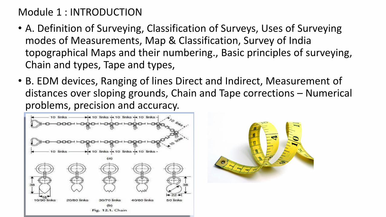
• A. Definition of Surveying, Classification of Surveys, Uses of Surveying modes of Measurements, Map & Classification, Survey of India topographical Maps and their numbering., Basic principles of surveying, Chain and types, Tape and types,
• B. EDM devices, Ranging of lines Direct and Indirect, Measurement of distances over sloping grounds, Chain and Tape corrections – Numerical problems, precision and accuracy.

Module 2 : COMPASS SURVEYING A. Meridians and bearings, Principle working and use of – Prismatic compass, Surveyor’s compass, Magnetic bearing, true bearings, WCB and Reduced bearing. Traverse - closed and open traverse, Computation of bearings of legs of closed traverse given the bearing of one of the legs, Computation of included angles given the bearings of legs of a closed traverse.
B. Dip and Declination Local attraction, determination and corrections, Dependent and independent co-ordinates, Omitted measurements
Module 3 :INTRODUCTION TO LEVELLING
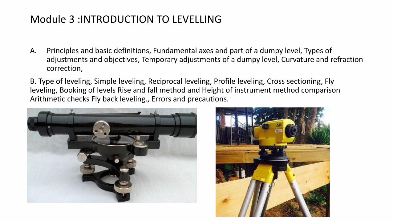
A. Principles and basic definitions, Fundamental axes and part of a dumpy level, Types of
adjustments and objectives, Temporary adjustments of a dumpy level, Curvature and refraction correction,
B. Type of leveling, Simple leveling, Reciprocal leveling, Profile leveling, Cross sectioning, Fly leveling, Booking of levels Rise and fall method and Height of instrument method comparison Arithmetic checks Fly back leveling., Errors and precautions.

• THEODOLITE SURVEYING:
• Theodolite and types, Fundamental axes and parts of Transit theodolite, uses of theodolite, Temporary adjustments of transit theodolite, measurement of horizontal and vertical angles.
• Trigonometric leveling (heights and distances-single plane and double plane method when the base is accessible and inaccessible.

Module 5: AREAS AND VOLUMES Calculation of area from cross staff surveying, Calculation of area of a closed traverse by coordinates method. Planimeter – principle of working and use of planimeter to measure areas, digital planimter, Computations of areas and volumes by trapezoidal and prismoidal rule,Capacity contours.

Surveying
Surveying is the art of determining the relative positions of points on, above or beneath the surface of the earth by means of direct or indirect measurements of distance. direction and elevation.
Levelling:
Levelling is a branch of surveying the object of which is
(I) to find the elevations of points with respect to a given or assumed datum, and
(II) to establish points at a given elevation or at different elevations with respect to a given or assumed datum.
The first operation is required to enable the works to be designed while the second operation is required in the setting out of all kinds of engineering works.
Levelling deals with measurements in a vertical plane.

Earth is an oblate spheroidal


19CIV35 Plane Surveying
Introduction
Mr. Yogesh K S, AP NHCE
Surveying is the art of determining the relative positions of points on, above or beneath
the surface of the earth by means of direct or indirect measurements of distance. direction
and elevation.
Levelling:
Levelling is a branch of surveying the object of which is
(I) to find the elevations of points with respect to a given or assumed datum, and
(II) to establish points at a given elevation or at different elevations with respect to a
given or assumed datum.
The first operation is required to enable the works to be designed while the second
operation is required in the setting out of all kinds of engineering works.
Levelling deals with measurements in a vertical plane.

19CIV35 Plane Surveying
Introduction
Mr. Yogesh K S, AP NHCE
Earth is an oblate spheroidal

19CIV35 Plane Surveying
Introduction
Mr. Yogesh K S, AP NHCE
Surveying is preliminarily divided into two types
1. Plane Surveying. 2. Geodetic Surveying
Plane Surveying. • Plane surveying is that type of surveying in which the mean surface of the earth is considered as a plane and the spheroidal
shape is neglected. • All triangles formed by survey lines are considered as plane triangles. • The level line is considered as straight and all plumb lines are considered parallel.
Geodetic Surveying Geodetic surveying is that type of surveying in which the shape of the earth is taken into account. All lines lying in the surface are curved lines and the triangles are spherical triangles. Involves spherical trigonometry. All geodetic surveys include work of larger magnitude and high degree of precision.

19CIV35 Plane Surveying
Classification
Mr. Yogesh K S, AP NHCE
Surveys may be classified under headings which define the uses or purpose of the resulting maps.
(A) CLASSIFICATION BASED UPON THE NATURE OF THE FIELD SURVEY. 1. Land Surveying. 1.1 Topographical Surveys . 1.2 Cadastral Surveys. 1.3 City Surveying. 2. Marine or Hydrographic Survey. 3. Astronomical Survey. (B) CLASSIFICATION BASED ON THE OBJECT OF SURVEY 1. Engineering Survey. 2. Military Survey. 3. Mine Survey. 4. Geological Survey.
19CIV35 Plane Surveying
Classification
Mr. Yogesh K S, AP NHCE
Surveys may be classified under headings which define the uses or purpose of the resulting maps.
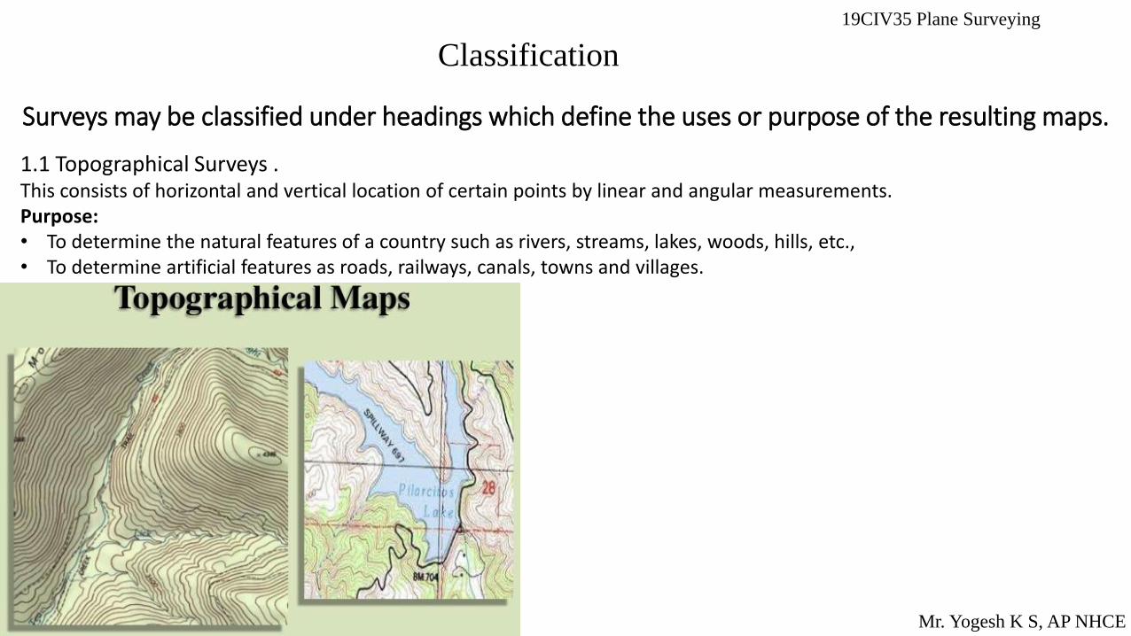
1.1 Topographical Surveys . This consists of horizontal and vertical location of certain points by linear and angular measurements. Purpose: • To determine the natural features of a country such as rivers, streams, lakes, woods, hills, etc., • To determine artificial features as roads, railways, canals, towns and villages.

19CIV35 Plane Surveying
Classification
Mr. Yogesh K S, AP NHCE
Surveys may be classified under headings which define the uses or purpose of the resulting maps.
1.2. Cadastral Surveys. Cadastral surveys are made incident to the fixing of property lines, the calculation of land area, or the transfer of land property from one owner. Purpose: • They are also made to fix the boundaries of municipalities and of State and Federal jurisdictions.
19CIV35 Plane Surveying
Classification
Mr. Yogesh K S, AP NHCE
Surveys may be classified under headings which define the uses or purpose of the resulting maps.
1.3. City Surveys. They are made in connection with the construction of streets. water supply systems, sewers and other works..

19CIV35 Plane Surveying
Classification
Mr. Yogesh K S, AP NHCE
1.3. City Surveys.

19CIV35 Plane Surveying
Classification
Mr. Yogesh K S, AP NHCE
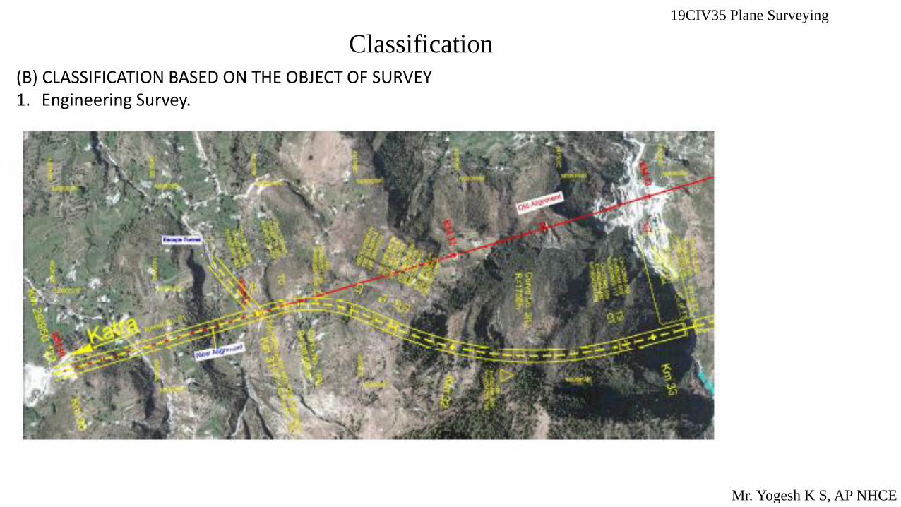
(B) CLASSIFICATION BASED ON THE OBJECT OF SURVEY 1. Engineering Survey. This is undertaken for the determination of quantities or to afford sufficient data for the designing of engineering works such as roads and reservoirs, or those connected with sewage disposal or water supply.
19CIV35 Plane Surveying
Classification
Mr. Yogesh K S, AP NHCE
(B) CLASSIFICATION BASED ON THE OBJECT OF SURVEY 1. Engineering Survey.

19CIV35 Plane Surveying
Classification
Mr. Yogesh K S, AP NHCE
(B) CLASSIFICATION BASED ON THE OBJECT OF SURVEY 2. Military Survey: This is used for determining points of strategic importance.
19CIV35 Plane Surveying
Classification
Mr. Yogesh K S, AP NHCE
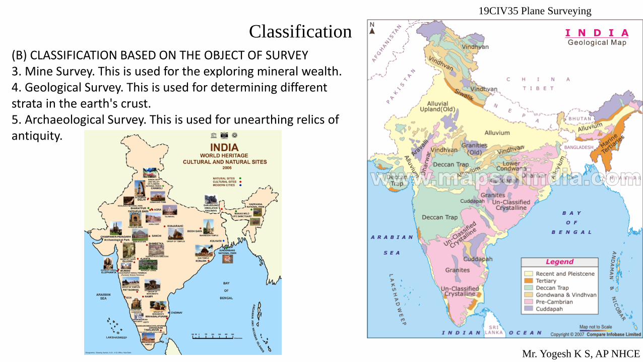
(B) CLASSIFICATION BASED ON THE OBJECT OF SURVEY 3. Mine Survey. This is used for the exploring mineral wealth. 4. Geological Survey. This is used for determining different strata in the earth's crust. 5. Archaeological Survey. This is used for unearthing relics of antiquity.
19CIV35 Plane Surveying
Classification
Mr. Yogesh K S, AP NHCE
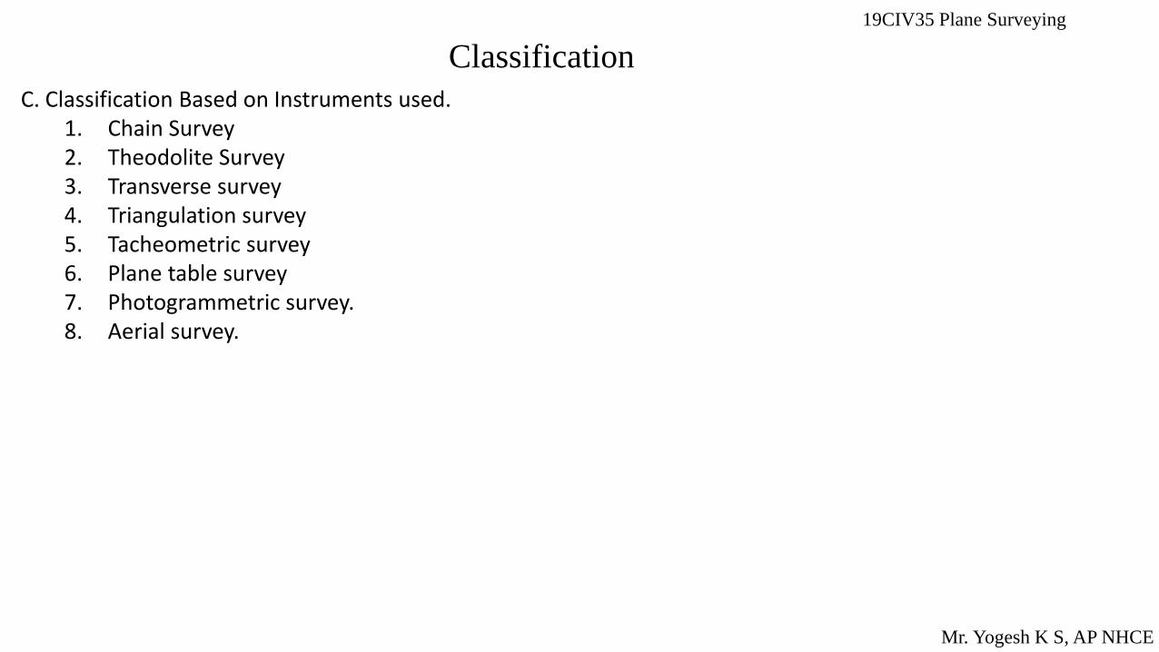
C. Classification Based on Instruments used. 1. Chain Survey 2. Theodolite Survey 3. Transverse survey 4. Triangulation survey 5. Tacheometric survey 6. Plane table survey 7. Photogrammetric survey. 8. Aerial survey.

Principles of Surveying
1. Location of a point by measurement from two points of reference
According to this principle, the relative position of a point to be surveyed should be located by measurement from at least two points of reference, the positions of which have already been fixed.
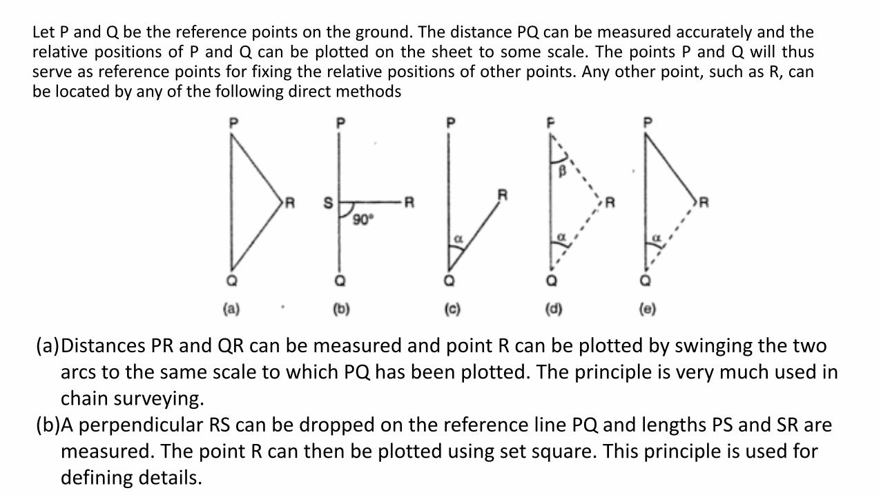
Let P and Q be the reference points on the ground. The distance PQ can be measured accurately and the relative positions of P and Q can be plotted on the sheet to some scale. The points P and Q will thus serve as reference points for fixing the relative positions of other points. Any other point, such as R, can be located by any of the following direct methods
(a)Distances PR and QR can be measured and point R can be plotted by swinging the two arcs to the same scale to which PQ has been plotted. The principle is very much used in chain surveying.
(b)A perpendicular RS can be dropped on the reference line PQ and lengths PS and SR are measured. The point R can then be plotted using set square. This principle is used for defining details.

(a)The distance QR and the angle PQR can be measured and point R is plotted either by means of a protractor or trigonometrically. This principle is used in traversing.
(b)In this method, the distances PR and QR are not measured but angle RPQ and angle RQP are measured with an angle-measuring instrument. Knowing the distance Pa, point R is plotted either by means of a protractor or by solution of triangle. PQR. This principle is very much used in triangulation and the method is used for very extensive work.
(c)Angle RQP and distance PR are measured and point R is plotted either by protracting an angle and swinging an arc from P or plotted trigonometrically. This principle, used in traversing is of minor utility.
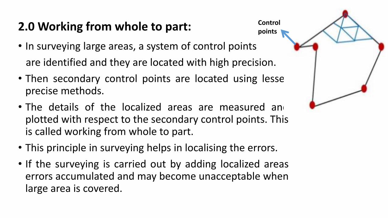
2.0 Working from whole to part:
• In surveying large areas, a system of control points
are identified and they are located with high precision.
• Then secondary control points are located using lesser precise methods.
• The details of the localized areas are measured and plotted with respect to the secondary control points. This is called working from whole to part.
• This principle in surveying helps in localising the errors.
• If the surveying is carried out by adding localized areas errors accumulated and may become unacceptable when large area is covered.
Control points

19CIV35 Plane Surveying
MAPS and PLANS
Mr. Yogesh K S, AP NHCE
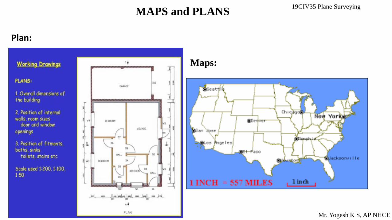
Plan: A plan is the graphical representation of the features near or
below the surface of the earth as projected on a horizontal plane
which is represented by plane of the paper on which the plan is
drawn to some scale.
Maps : Map is constructed by orthographic projection without measurable
distortion. The representation is called a map if the scale is small , while it is
called a plan if the scale is large.
19CIV35 Plane Surveying MAPS and PLANS
Mr. Yogesh K S, AP NHCE
Plan:
Maps:

19CIV35 Plane Surveying
Mr. Yogesh K S, AP NHCE
SCALE
The area that is surveyed is vast and, therefore, plans are made to some scale. Scale is the fixed ratio that every distance on the plan bears with corresponding distance on the ground. Scale can be represented by' the following methods . 1. One cm on the plan represents some whole number of metres on the ground, such as 1 cm = 10 m etc. This type
of scale is called engineer's scale. 2. One unit of length on the plan represents some number of same units of length on the ground. such as 1/1000
etc. This ratio of map distance to the corresponding ground distance is independent of units of measurement and is called representative fraction.
For example 1cm=50m R.F=1
50𝑋100=
1
5000=1:5000
Choice of Scale of a Map : The most common scales for ordinary maps are those in which the number of metres represented by one centimetre is some multiple of ten. The following two general rules should be followed : 1. Choose a scale large enough so that in plotting or in scaling distance from the finished map. it will not be
necessary to read the scale closer than 0.25 mm. 2. Choose as small a scale as is consistent with a clear delineation of the smallest details to be plotted .

19CIV35 Plane Surveying
Mr. Yogesh K S, AP NHCE

19CIV35 Plane Surveying
Mr. Yogesh K S, AP NHCE
Linear measurements There are various methods of making linear measurements and their relative merit depends upon the degree of precision required. They can be mainly divided into three heads : 1. Direct measurements. 2. Measurements by optical means. 3. Electra-magnetic methods. In the case of direct measurements, distances are actually measured on the ground
with help of a chain or a tape or any other instrument. In the optical methods, observations are taken through a telescope and calculations are
done for the distances, such as in tacheometry or triangulation. In the electro-magnetic methods, distances are measured with instruments that rely on
propagation, reflection and subsequent reception of either radio waves, light waves or infrared waves.
19CIV35 Plane Surveying
Mr. Yogesh K S, AP NHCE
Linear measurements There are various methods of making linear measurements and their relative merit depends upon the
degree of precision required. They can be mainly divided into three heads :
1. Direct measurements.
2. Measurements by optical means.
3. Electra-magnetic methods.
In the case of direct measurements, distances are actually measured on the ground with help of a chain
or a tape or any other instrument.
In the optical methods, observations are taken through a telescope and calculations are done for the
distances, such as in tacheometry or triangulation.
In the electro-magnetic methods, distances are measured with instruments that rely on propagation,
reflection and subsequent reception of either radio waves, light waves or infrared waves.
19CIV35 Plane Surveying
Mr. Yogesh K S, AP NHCE
Linear measurements Direct measurements.
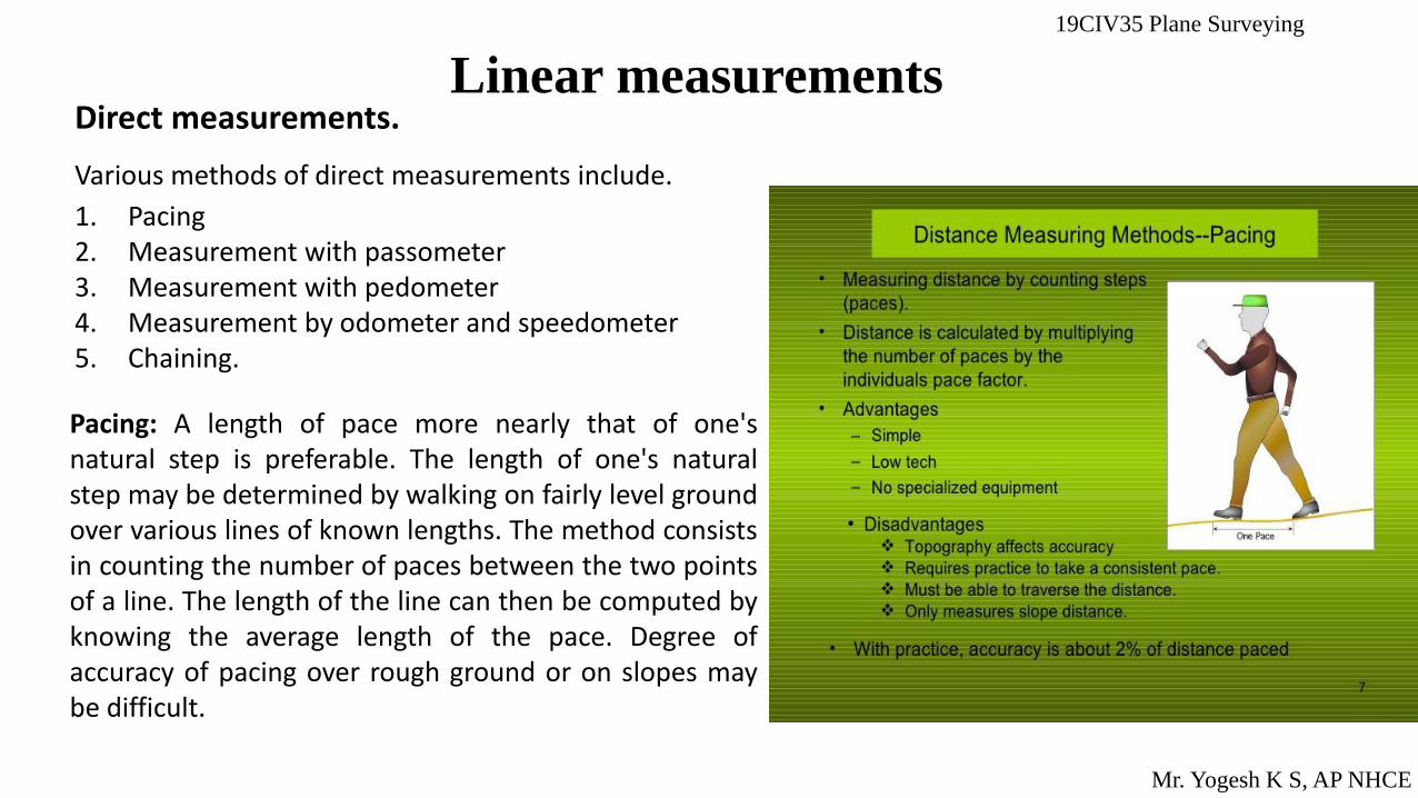
Various methods of direct measurements include.
1. Pacing 2. Measurement with passometer 3. Measurement with pedometer 4. Measurement by odometer and speedometer 5. Chaining.
Pacing: A length of pace more nearly that of one's natural step is preferable. The length of one's natural step may be determined by walking on fairly level ground over various lines of known lengths. The method consists in counting the number of paces between the two points of a line. The length of the line can then be computed by knowing the average length of the pace. Degree of accuracy of pacing over rough ground or on slopes may be difficult.
19CIV35 Plane Surveying
Mr. Yogesh K S, AP NHCE
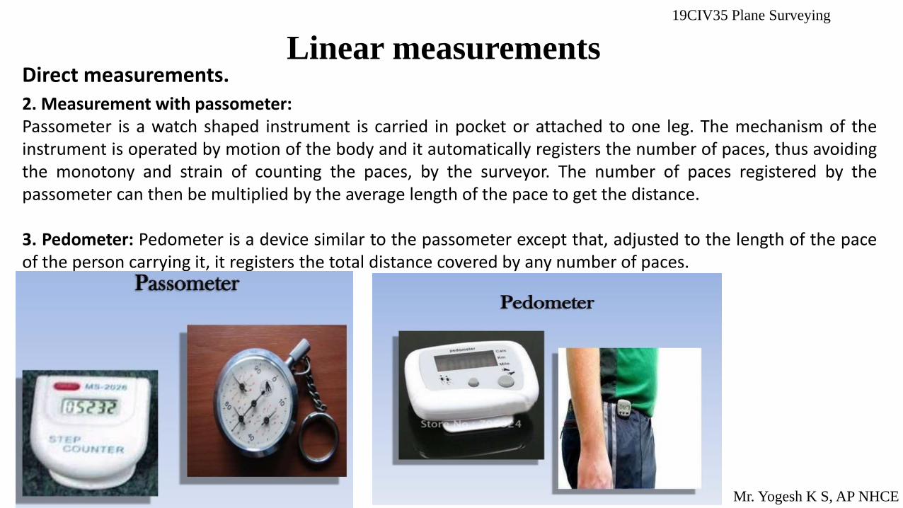
Linear measurements Direct measurements. 2. Measurement with passometer: Passometer is a watch shaped instrument is carried in pocket or attached to one leg. The mechanism of the instrument is operated by motion of the body and it automatically registers the number of paces, thus avoiding the monotony and strain of counting the paces, by the surveyor. The number of paces registered by the passometer can then be multiplied by the average length of the pace to get the distance. 3. Pedometer: Pedometer is a device similar to the passometer except that, adjusted to the length of the pace of the person carrying it, it registers the total distance covered by any number of paces.
19CIV35 Plane Surveying
Mr. Yogesh K S, AP NHCE
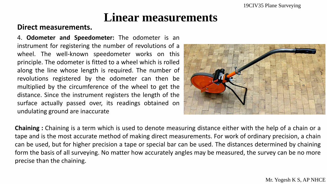
Linear measurements Direct measurements. 4. Odometer and Speedometer: The odometer is an instrument for registering the number of revolutions of a wheel. The well-known speedometer works on this principle. The odometer is fitted to a wheel which is rolled along the line whose length is required. The number of revolutions registered by the odometer can then be multiplied by the circumference of the wheel to get the distance. Since the instrument registers the length of the surface actually passed over, its readings obtained on undulating ground are inaccurate
Chaining : Chaining is a term which is used to denote measuring distance either with the help of a chain or a tape and is the most accurate method of making direct measurements. For work of ordinary precision, a chain can be used, but for higher precision a tape or special bar can be used. The distances determined by chaining form the basis of all surveying. No matter how accurately angles may be measured, the survey can be no more precise than the chaining.
19CIV35 Plane Surveying
Mr. Yogesh K S, AP NHCE
Linear measurements
INSTRUMENTS FOR CHAINING: The various instruments used for the determination of the length of line by chaining are as follows : I. Chain or tape 2. Arrows 3. Pegs 4. Ranging rods 5. Offset rods 6. Plasterer's laths and whites 7. Plumb bob.
CHAIN Chains are formed of straight links of galvanised mild steel wire bent into rings at the ends and joined each
other by three small circular or oval wire rings. These rings offer flexibility to the chain. The ends of the chain are
provided with brass handle at each end with swivel joint, so that the chain can be turned without twisting. The length of
a link is the distance between the centres of two consecutive middle rings, while the length of the chain is measured
from the outside of one handle to the outside of the other handle.
Following are various types of chains in common use :
(1) Metric chains
(2) Gunter's chain or Surveyor's chain
(3) Engineer's chain
(4) Revenue chain
(5) Steel band or band chain.

19CIV35 Plane Surveying
Mr. Yogesh K S, AP NHCE
Linear measurements Metric chains : Metric chains are generally available in lengths of 5, 10, 20 and 30 metres. IS : 1492-1970 coven the requirements of metric surveying chains. To enable the reading of fractions of a chain without much difficulty, tallies are fixed at every metre length for chains of 5 m and 10 m lengths
19CIV35 Plane Surveying
Mr. Yogesh K S, AP NHCE
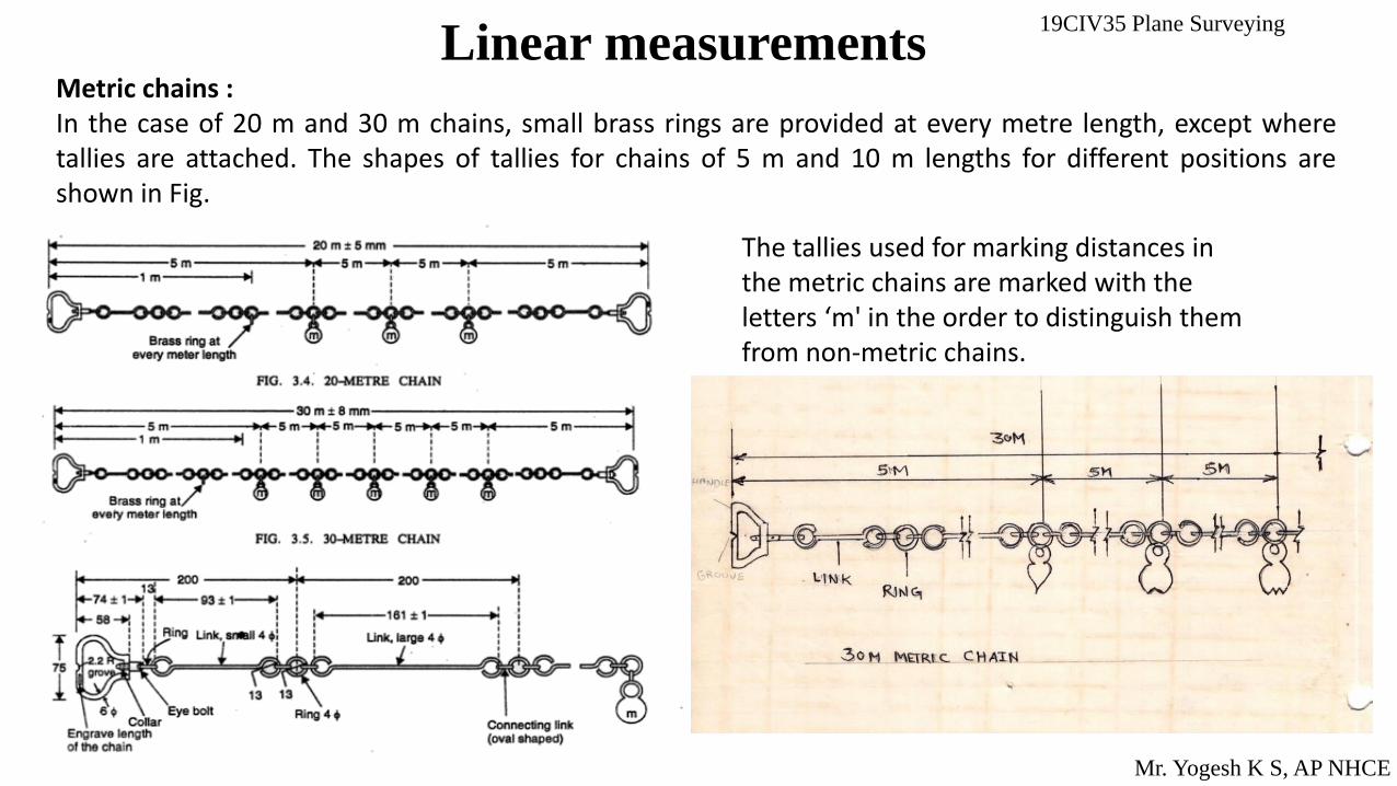
Linear measurements Metric chains : In the case of 20 m and 30 m chains, small brass rings are provided at every metre length, except where tallies are attached. The shapes of tallies for chains of 5 m and 10 m lengths for different positions are shown in Fig.
The tallies used for marking distances in the metric chains are marked with the letters ‘m' in the order to distinguish them from non-metric chains.
19CIV35 Plane Surveying
Mr. Yogesh K S, AP NHCE
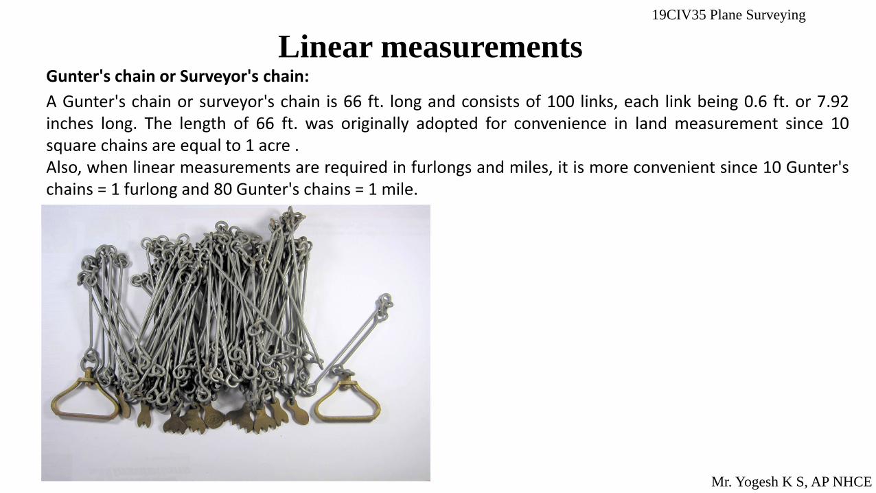
Linear measurements Gunter's chain or Surveyor's chain:
A Gunter's chain or surveyor's chain is 66 ft. long and consists of 100 links, each link being 0.6 ft. or 7.92 inches long. The length of 66 ft. was originally adopted for convenience in land measurement since 10 square chains are equal to 1 acre . Also, when linear measurements are required in furlongs and miles, it is more convenient since 10 Gunter's chains = 1 furlong and 80 Gunter's chains = 1 mile.

19CIV35 Plane Surveying
Mr. Yogesh K S, AP NHCE
Linear measurements Engineer's Chain: The engineer's chain is 100 ft. long and consists of 100 links, each link being 1 ft. long. At every 10 links, brass tags are fastened, with notches on the tags indicating the number of 10 link segments between the tag and end of the chain. The distances measured are recorded in feet and decimals.
Revenue Chain: The revenue chain is 33 ft. long and consists of 16 links, each link being *5. ft. long. The chain is mainly used for measuring fields in cadastral survey.

19CIV35 Plane Surveying
Linear measurements Steel Band: The steel band consists of a long narrow strip of blue steel, of uniform width of 12 to 16 mm and thickness of 0.3 to 0.6 mm. Metric steel bands are available in lengths of 20 or 30 m. • It is divided by brass studs at every 20 cm and numbered at every metre. The first and last links (20 cm length) are
subdivided into cm and mm. • For convenience in handling and carrying, steel bands are almost invariably wound on special steel crosses or metal
reels from which they can be easily unrolled. • For accurate work, the steel band should always be used in preference to the chain, but it should only be placed in
the hands of careful chainmen. • Its chief disadvantage is that it is easily broken and difficult to repair in the field.
Mr. Yogesh K S, AP NHCE

19CIV35 Plane Surveying
Linear measurements
Mr. Yogesh K S, AP NHCE
TAPES : Tapes are used for more accurate measurements and are classed according to the material of which they are made, such as follows: (i) cloth or linen tape (ii) metallic tape (iii) steel tape and (iv) invar tape.
Cloth or Linen Tape: Cloth tapes of closely woven linen, 12 to 15 mm wide varnished to resist moisture, are light and flexible and may be used for taking comparatively rough and subsidiary measurements such as offsets. • A cloth tape is commonly available in lengths of 10 metres, 20 metres, 25 metres and 30 metres, and in 33 ft., 50 ft.,
66 ft. and 100 ft. A cloth tape is rarely used for making accurate measurements. because of the following reasons : 1. It is easily affected by moisture or dampness and thus shrinks ; 2. Its length gets altered by stretching and it is likely to twist and tangle ; 3. It is not strong. Before winding up the tape in the case, it should be cleaned and dried.
19CIV35 Plane Surveying
Linear measurements
Mr. Yogesh K S, AP NHCE
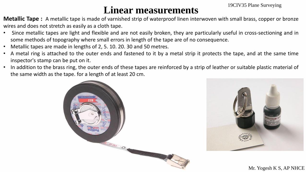
Metallic Tape : A metallic tape is made of varnished strip of waterproof linen interwoven with small brass, copper or bronze wires and does not stretch as easily as a cloth tape. • Since metallic tapes are light and flexible and are not easily broken, they are particularly useful in cross-sectioning and in
some methods of topography where small errors in length of the tape are of no consequence. • Metallic tapes are made in lengths of 2, 5. 10. 20. 30 and 50 metres. • A metal ring is attached to the outer ends and fastened to it by a metal strip it protects the tape, and at the same time
inspector's stamp can be put on it. • In addition to the brass ring, the outer ends of these tapes are reinforced by a strip of leather or suitable plastic material of
the same width as the tape. for a length of at least 20 cm.

19CIV35 Plane Surveying
Linear measurements
Mr. Yogesh K S, AP NHCE
Steel Tape: Steel tapes vary in quality and accuracy of graduation, but even a poor steel tape is generally superior to a cloth or metallic tape for most of the linear measurements that are made in surveying. • A steel tape consists of a light strip of width 6 to 10 mm and is more accurately graduated. • Steel tapes are available in lengths of 1. 2, 10, 20, 30 and 50 metres. The tapes of 10. 20. 30 and 50 metre lengths, are
provided with a brass ring at the outer end, fastened to it by a metal strip of the same width as the tape. • A steel tape is a delicate instrument and is very light, and therefore, cannot withstand rough usage. The tape should be
wiped clean and dry after using, and should be oiled with a little mineral oil, so that it does not get rusted.
19CIV35 Plane Surveying
Linear measurements
Mr. Yogesh K S, AP NHCE
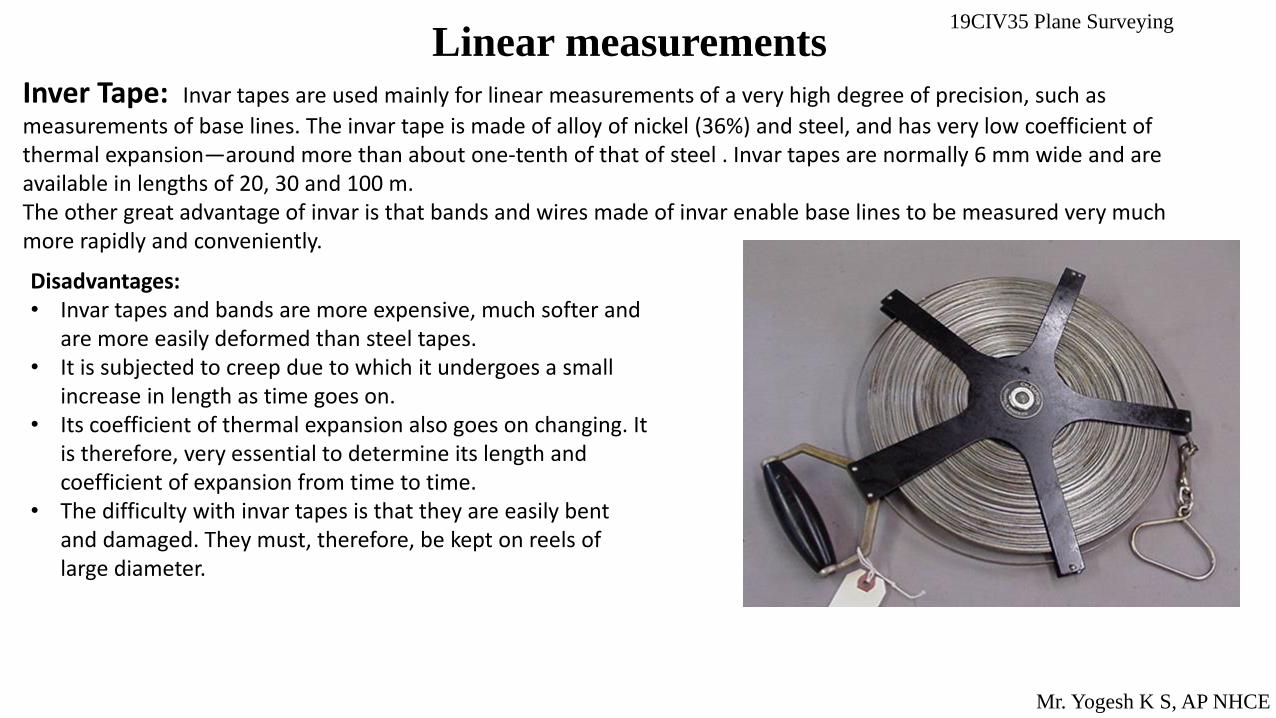
Inver Tape: Invar tapes are used mainly for linear measurements of a very high degree of precision, such as
measurements of base lines. The invar tape is made of alloy of nickel (36%) and steel, and has very low coefficient of thermal expansion—around more than about one-tenth of that of steel . Invar tapes are normally 6 mm wide and are available in lengths of 20, 30 and 100 m. The other great advantage of invar is that bands and wires made of invar enable base lines to be measured very much more rapidly and conveniently.
Disadvantages: • Invar tapes and bands are more expensive, much softer and
are more easily deformed than steel tapes. • It is subjected to creep due to which it undergoes a small
increase in length as time goes on. • Its coefficient of thermal expansion also goes on changing. It
is therefore, very essential to determine its length and coefficient of expansion from time to time.
• The difficulty with invar tapes is that they are easily bent and damaged. They must, therefore, be kept on reels of large diameter.
19CIV35 Plane Surveying
Linear measurements
Mr. Yogesh K S, AP NHCE
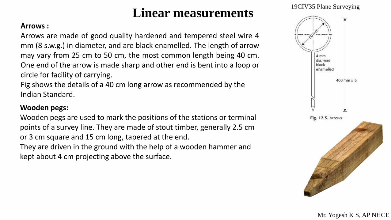
Arrows : Arrows are made of good quality hardened and tempered steel wire 4 mm (8 s.w.g.) in diameter, and are black enamelled. The length of arrow may vary from 25 cm to 50 cm, the most common length being 40 cm. One end of the arrow is made sharp and other end is bent into a loop or circle for facility of carrying. Fig shows the details of a 40 cm long arrow as recommended by the Indian Standard.
Wooden pegs: Wooden pegs are used to mark the positions of the stations or terminal points of a survey line. They are made of stout timber, generally 2.5 cm or 3 cm square and 15 cm long, tapered at the end. They are driven in the ground with the help of a wooden hammer and kept about 4 cm projecting above the surface.
19CIV35 Plane Surveying
Linear measurements
Mr. Yogesh K S, AP NHCE
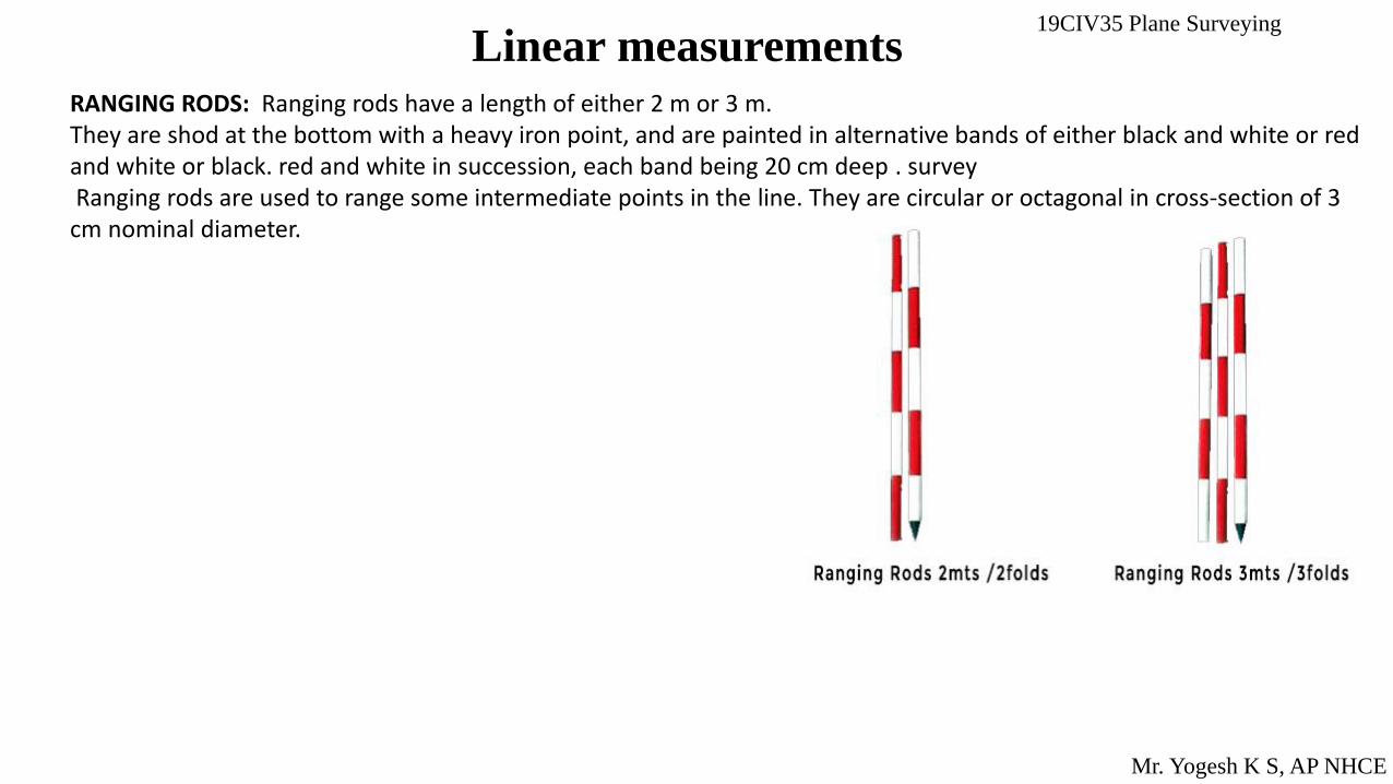
RANGING RODS: Ranging rods have a length of either 2 m or 3 m. They are shod at the bottom with a heavy iron point, and are painted in alternative bands of either black and white or red and white or black. red and white in succession, each band being 20 cm deep . survey Ranging rods are used to range some intermediate points in the line. They are circular or octagonal in cross-section of 3 cm nominal diameter.
19CIV35 Plane Surveying
Linear measurements
Mr. Yogesh K S, AP NHCE
RANGING OUT SURVEY LINES
While measuring the length of a survey line or 'chain line', the chain or tape must be stretched straight
along the line joining its two terminal stations.
If the length of line is less than the length of the chain, there will be no difficulty, in doing; so. If,
however, the length of the line exceeds the length of the chain, some intermediate points will have to
be established in line with the two terminal points before chaining is started. The process of fixing or
establishing such intermediate points is known as ranging.
There are two methods of ranging: (I) Direct ranging. (ii) Indirect ranging.

19CIV35 Plane Surveying
Linear measurements
Mr. Yogesh K S, AP NHCE
Direct ranging:
Ranging by eye:

19CIV35 Plane Surveying
Linear measurements
Mr. Yogesh K S, AP NHCE
Ranging by Line Ranger:
19CIV35 Plane Surveying
Linear measurements
Mr. Yogesh K S, AP NHCE
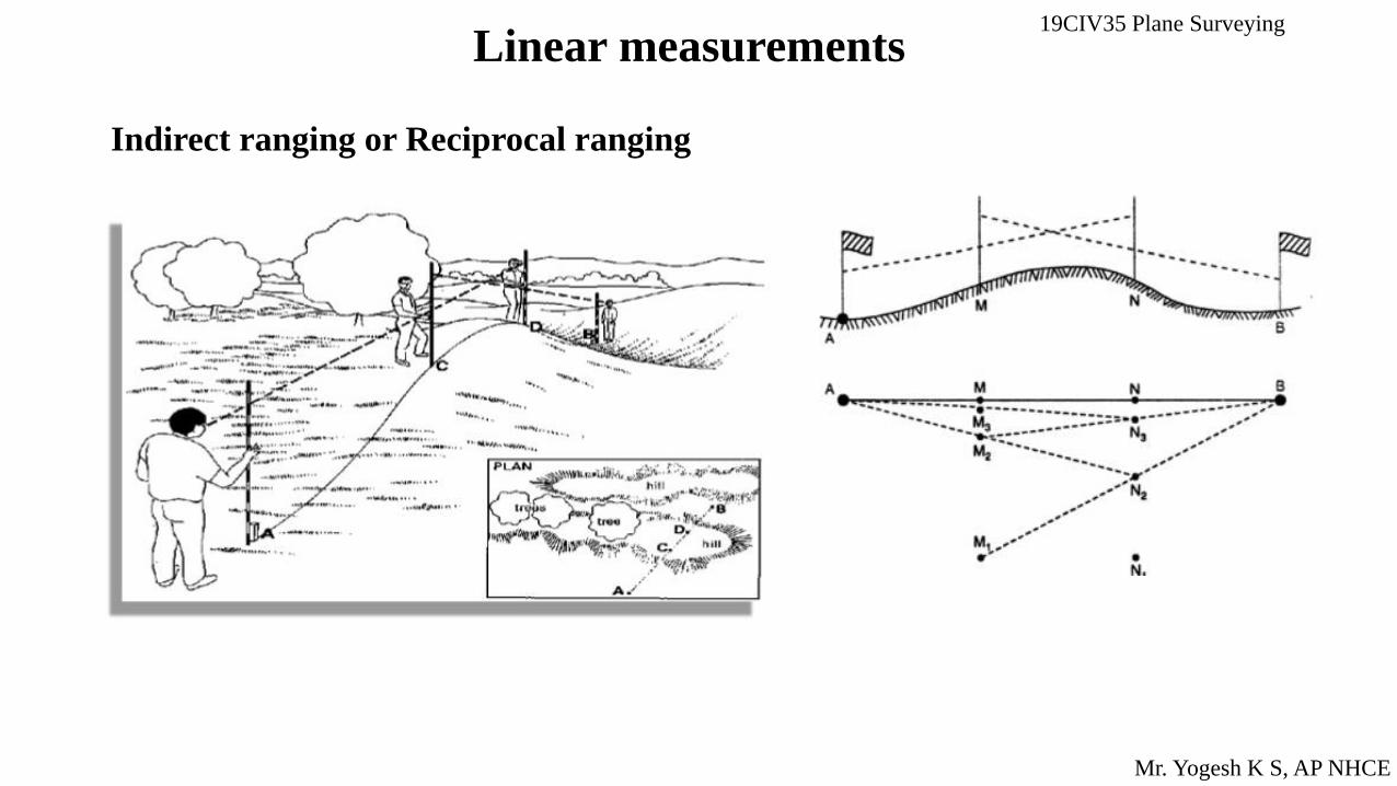
Indirect ranging or Reciprocal ranging
19CIV35 Plane Surveying
Linear measurements
Mr. Yogesh K S, AP NHCE
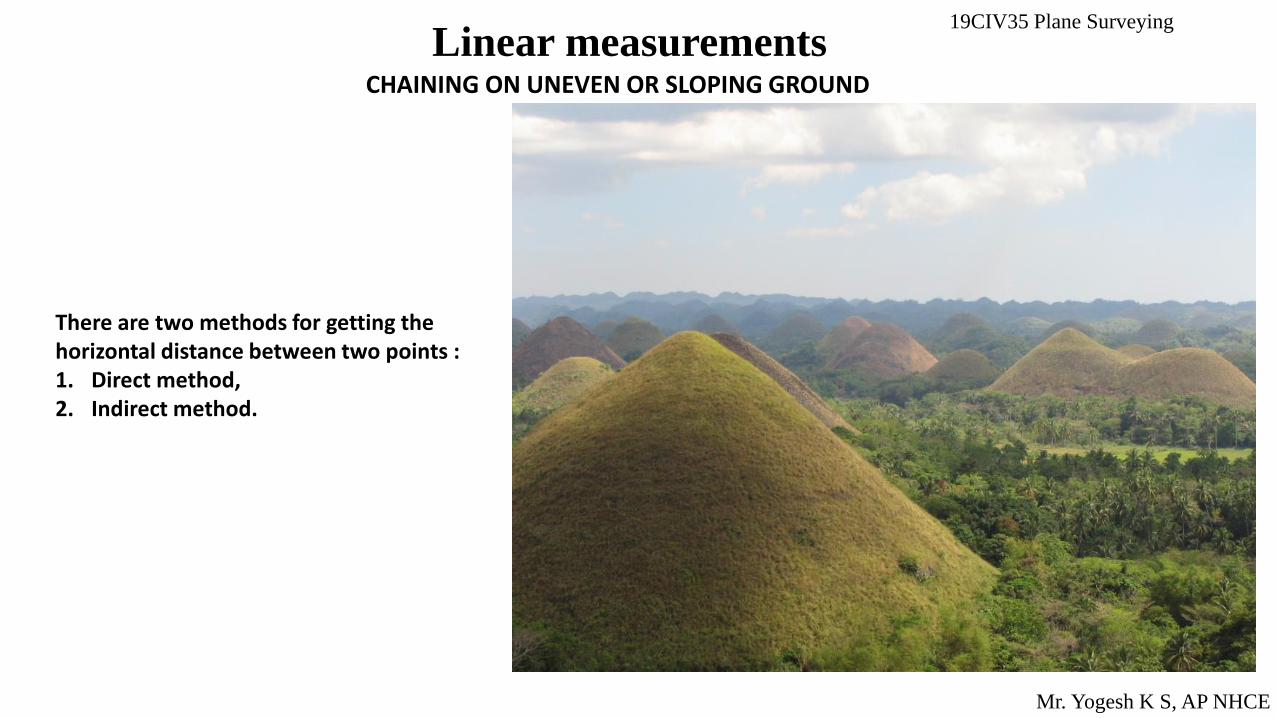
CHAINING ON UNEVEN OR SLOPING GROUND
There are two methods for getting the horizontal distance between two points : 1. Direct method, 2. Indirect method.
19CIV35 Plane Surveying
Linear measurements
Mr. Yogesh K S, AP NHCE
CHAINING ON UNEVEN OR SLOPING GROUND
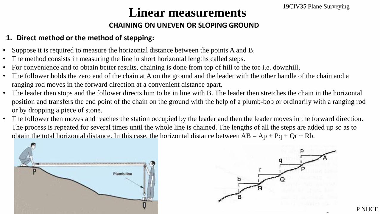
1. Direct method or the method of stepping:
• Suppose it is required to measure the horizontal distance between the points A and B.
• The method consists in measuring the line in short horizontal lengths called steps.
• For convenience and to obtain better results, chaining is done from top of hill to the toe i.e. downhill.
• The follower holds the zero end of the chain at A on the ground and the leader with the other handle of the chain and a
ranging rod moves in the forward direction at a convenient distance apart.
• The leader then stops and the follower directs him to be in line with B. The leader then stretches the chain in the horizontal
position and transfers the end point of the chain on the ground with the help of a plumb-bob or ordinarily with a ranging rod
or by dropping a piece of stone.
• The follower then moves and reaches the station occupied by the leader and then the leader moves in the forward direction.
The process is repeated for several times until the whole line is chained. The lengths of all the steps are added up so as to
obtain the total horizontal distance. In this case, the horizontal distance between AB = Ap + Pq + Qr + Rb.

19CIV35 Plane Surveying
Linear measurements
Mr. Yogesh K S, AP NHCE
CHAINING ON UNEVEN OR SLOPING GROUND 1. Indirect method : Angle measured. Difference in level measured. Hypotenusal allowance (i) Angle measured:
The distance along the slope is measured and then the angle
of slope i.e. angle between the sloping ground and the
horizontal surface is found with the help of Abney’s level
or precisely with theodolite. Knowing the sloping distance
say I and angle of slope say α horizontal distance, D can be
calculated by the relation, D1 = L cos ɵ1

19CIV35 Plane Surveying
Linear measurements
Mr. Yogesh K S, AP NHCE
CHAINING ON UNEVEN OR SLOPING GROUND
Difference in level measured. Sometimes, in the place of measuring the angle ɵ. the difference in the level between the points is measured with the help of a levelling instrument and the horizontal distance is computed.
Thus, if it is the difference in level, we have D= 𝑙2 − ℎ2
19CIV35 Plane Surveying
Linear measurements
Mr. Yogesh K S, AP NHCE
CHAINING ON UNEVEN OR SLOPING GROUND
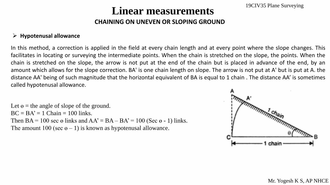
Hypotenusal allowance
In this method, a correction is applied in the field at every chain length and at every point where the slope changes. This facilitates in locating or surveying the intermediate points. When the chain is stretched on the slope, the points. When the chain is stretched on the slope, the arrow is not put at the end of the chain but is placed in advance of the end, by an amount which allows for the slope correction. BA' is one chain length on slope. The arrow is not put at A' but is put at A. the distance AA' being of such magnitude that the horizontal equivalent of BA is equal to 1 chain . The distance AA’ is sometimes called hypotenusal allowance.
Let ɵ = the angle of slope of the ground.
BC = BA’ = 1 Chain = 100 links.
Then BA = 100 sec ɵ links and AA’ = BA – BA’ = 100 (Sec ɵ - 1) links.
The amount 100 (sec ɵ – 1) is known as hypotenusal allowance.

19CIV35 Plane Surveying
Linear measurements
Mr. Yogesh K S, AP NHCE
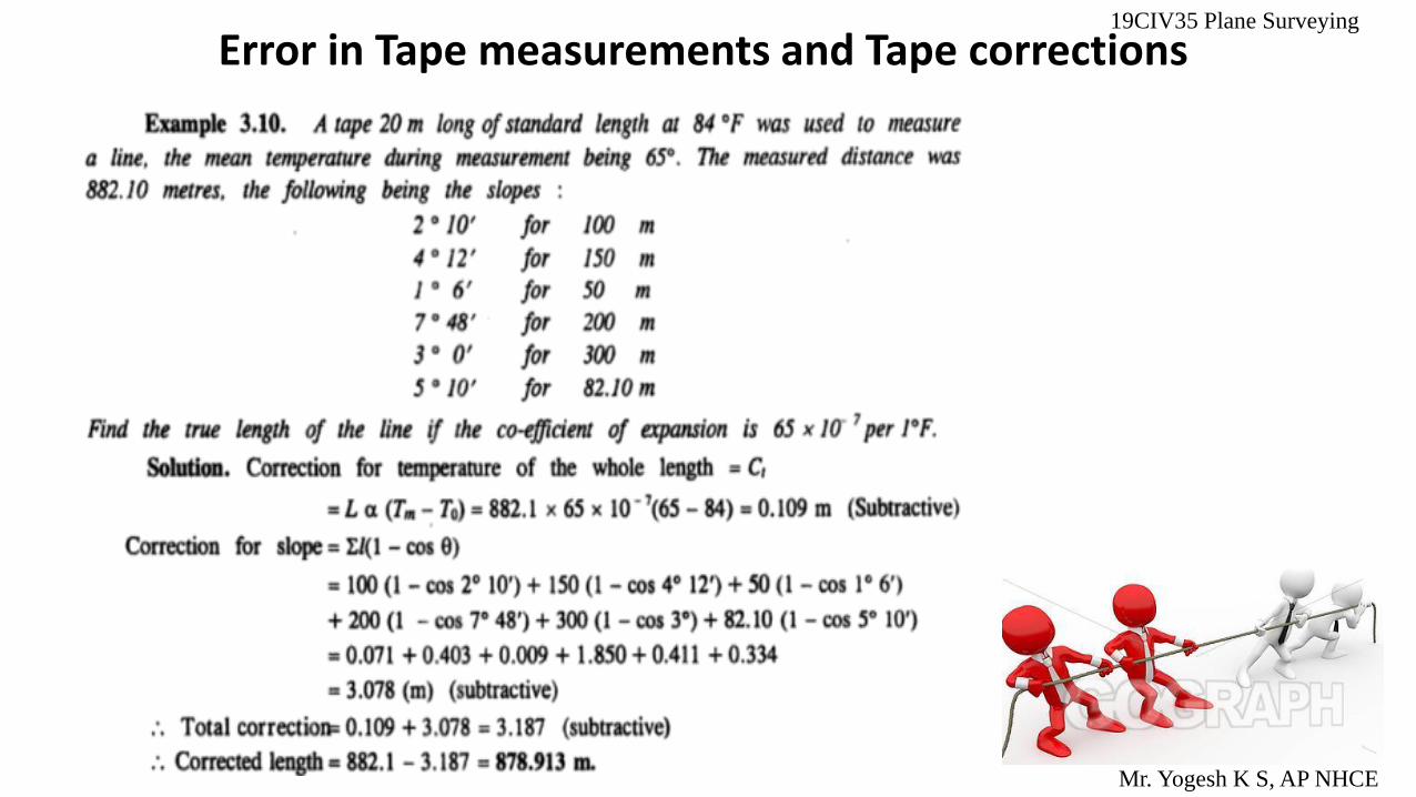
Error in Tape measurements and Tape corrections
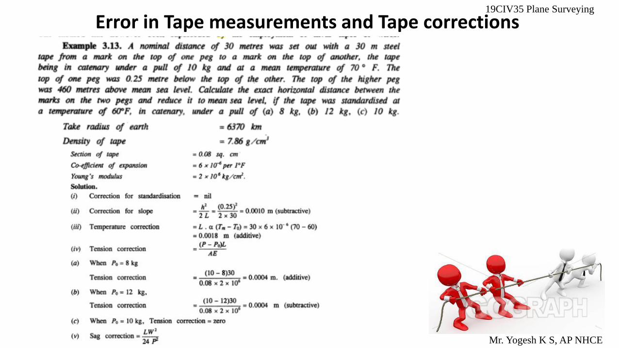
Since in most of the cases a tape is used for precise work, the corrections are sometimes called as 'tape corrections.', Though they can also be applied to the measurements taken with a chain or with a steel band. A correction is positive when the erroneous or uncorrected length is to be increased and negative when it is to be decreased to get the true length. Tape measurements require certain corrections to be applied to the measured distance depending upon the conditions under which the measurements have been made.
19CIV35 Plane Surveying
Linear measurements
Mr. Yogesh K S, AP NHCE
Error in Tape measurements and Tape corrections
1. Correction for absolute length
2. Correction for temperature.
3. Correction for pull or tension.
4. Correction for sag.
5. Correction for slope.
6. Correction for alignment.
7. Reduction to sea level.
8. Correction to measurement in
vertical plane
After having measured the length, the correct length of the base is
calculated by applying the following corrections :

Correction for Absolute Length
Due to manufacturing defects the absolute length of the tape may be different from its designated or nominal length.
Also with use the tape may stretch causing change in the length and it is imperative that the tape is regularly checked under standard conditions to determine its absolute length.
The correction for absolute length or standardization is given by
Ca=𝑪
𝒍 *L
Error in Tape measurements and Tape corrections
where c = the correction per tape length, l = the designated or nominal length of the tape, and L= the measured length of the line.
If the absolute length is more than the nominal length the sign of the correction is positive and vice versa.
19CIV35 Plane Surveying
Mr. Yogesh K S, AP NHCE

Correction for Temperature:
If the tape is used at a field temperature different from the standardization temperature then the temperature correction to the measured length is
Ct=∝(Tm-To)L
Error in Tape measurements and Tape corrections
where α = the coefficient of thermal expansion of the tape material, Tm = the mean field temperature, and To = the standardization temperature. The sign of the correction takes the sign of (Tm-To).
19CIV35 Plane Surveying
Mr. Yogesh K S, AP NHCE
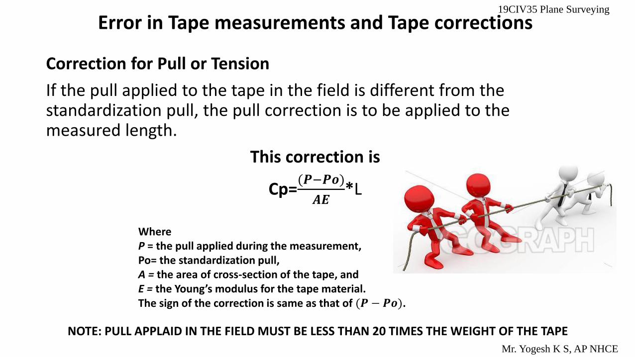
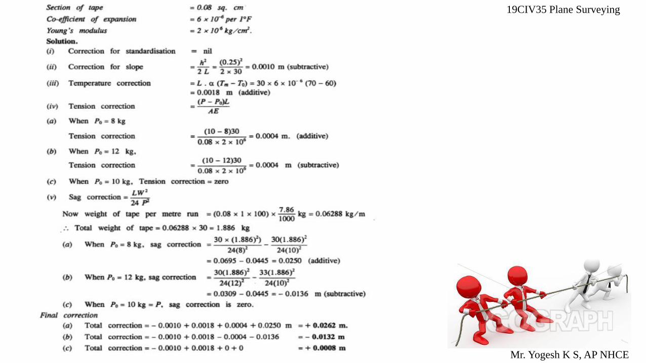
Correction for Pull or Tension
If the pull applied to the tape in the field is different from the standardization pull, the pull correction is to be applied to the measured length.
This correction is
Cp=(𝑷−𝑷𝒐)
𝑨𝑬*L
Error in Tape measurements and Tape corrections
Where P = the pull applied during the measurement, Po= the standardization pull, A = the area of cross-section of the tape, and E = the Young’s modulus for the tape material. The sign of the correction is same as that of (𝑷 − 𝑷𝒐).
NOTE: PULL APPLAID IN THE FIELD MUST BE LESS THAN 20 TIMES THE WEIGHT OF THE TAPE
19CIV35 Plane Surveying
Mr. Yogesh K S, AP NHCE

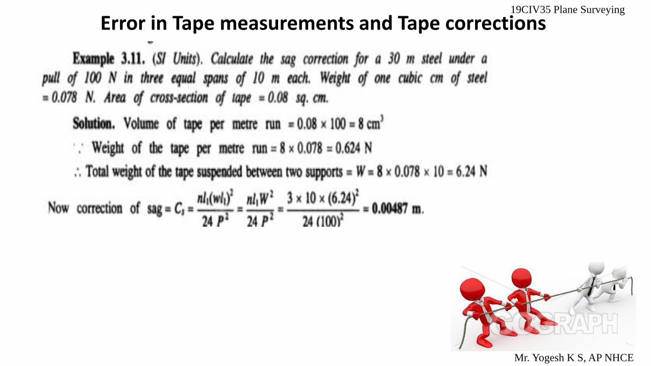
SAG Correction
For very accurate measurements the tape can be allowed to hang in catenary between two supports. In the case of long tape, intermediate supports as shown in Fig, can be used to reduce the magnitude of correction.
This correction is
Cg=𝟏
𝟐𝟒
𝑾
𝑷
𝟐
*L
Error in Tape measurements and Tape corrections
Where P = the pull applied during the measurement, W = the weight of the tape per span length.
19CIV35 Plane Surveying
Mr. Yogesh K S, AP NHCE
The sign of this correction is always negative.

Correction for Slope
If the length L is measured on the slope as shown in Fig. it must be reduced to its horizontal equivalent L cos θ.
The required slope correction is
Cs = (1− cos θ)L (exact)
Cs=𝒉𝟐
𝟐𝒍 (approximate)
Error in Tape measurements and Tape corrections 19CIV35 Plane Surveying
Mr. Yogesh K S, AP NHCE
The sign of this correction is always negative. where θ = the angle of the slope, and h = the difference in elevation of the ends of the tape. The sign of this correction is always negative.
Error in Tape measurements and Tape corrections 19CIV35 Plane Surveying
Mr. Yogesh K S, AP NHCE
Error in Tape measurements and Tape corrections 19CIV35 Plane Surveying
Mr. Yogesh K S, AP NHCE

Error in Tape measurements and Tape corrections 19CIV35 Plane Surveying
Mr. Yogesh K S, AP NHCE
Error in Tape measurements and Tape corrections 19CIV35 Plane Surveying
Mr. Yogesh K S, AP NHCE
19CIV35 Plane Surveying
Mr. Yogesh K S, AP NHCE

CIV 35 Plain Surveying
Module-2
Mr. Yogesh K S, AP NHCE
COMPASS SURVEYING
Chain surveying can be used when the area to be surveyed is comparatively small and is fairly flat, but when
the area is large, undulated and crowded with many details, triangulation (which is the principle of chain
survey) is not possible. In such an area, the method of traversing is adopted.
Traversing : In Traversing, the framework consist of a number of
connected lines. The length are measured by a chain or a tape and
the directions measured by angle measuring instruments. In one of
the methods, the angle (direction) measuring instrument is the
compass.
Hence, in compass surveying directions of survey lines are
determined with a compass and the length of the lines are measured
with a tape or a chain. This process is known as Compass Traversing

CIV 35 Plain Surveying
Mr. Yogesh K S, AP NHCE
COMPASS SURVEYING Instruments used for direct measurement of directions.
1. Surveyor’s compass.
2. Prismatic compass.
Instruments for measuring angles
1. Sextant.
2. Theodolite.
Surveyor’s compass.
Prismatic compass.
Sextant. Theodolite.
Module-2
CIV 35 Plain Surveying
Mr. Yogesh K S, AP NHCE
COMPASS SURVEYING Module-2
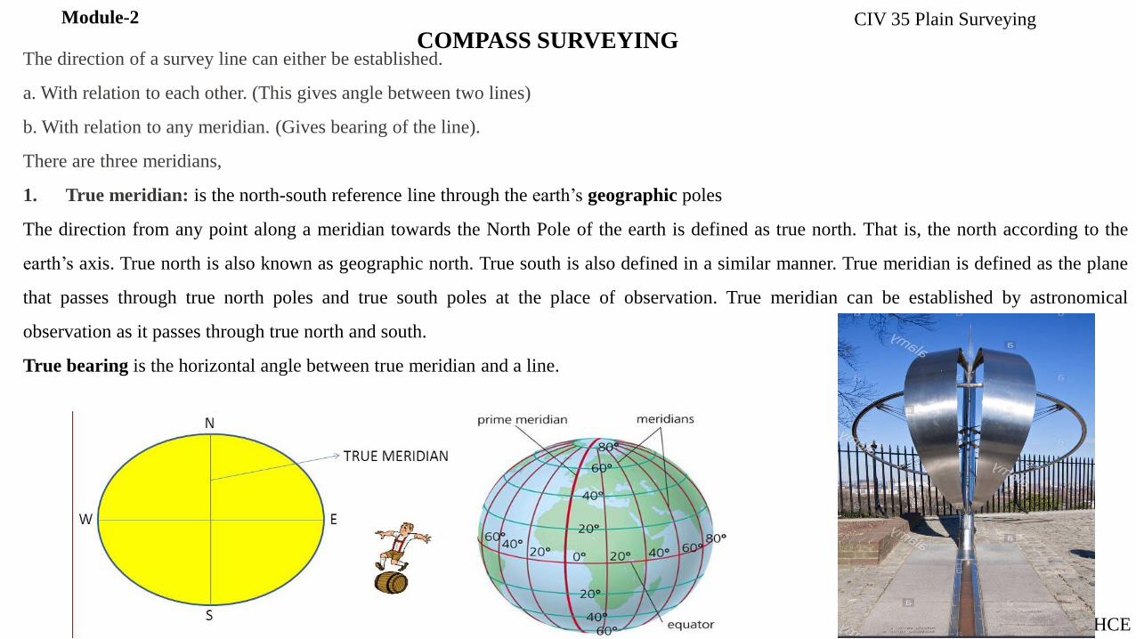
The direction of a survey line can either be established.
a. With relation to each other. (This gives angle between two lines)
b. With relation to any meridian. (Gives bearing of the line).
There are three meridians,
1. True meridian: is the north-south reference line through the earth’s geographic poles
The direction from any point along a meridian towards the North Pole of the earth is defined as true north. That is, the north according to the
earth’s axis. True north is also known as geographic north. True south is also defined in a similar manner. True meridian is defined as the plane
that passes through true north poles and true south poles at the place of observation. True meridian can be established by astronomical
observation as it passes through true north and south.
True bearing is the horizontal angle between true meridian and a line.

CIV 35 Plain Surveying
Mr. Yogesh K S, AP NHCE
COMPASS SURVEYING Module-2
2. Magnetic meridian: Magnetic meridian is a north-south reference line as defined by the earth’s magnetic field.
The magnetic meridian is an equivalent imaginary line connecting the magnetic south and north poles and can be
taken as the horizontal component of magnetic force lines along the surface of the earth. Therefore, a compass
needle will be parallel to the magnetic meridian.
Magnetic Bearing: The magnetic bearing of a line is the horizontal angle which it makes with the magnetic
meridian passing through one of the extremities of the line.
CIV 35 Plain Surveying
Mr. Yogesh K S, AP NHCE
COMPASS SURVEYING Module-2
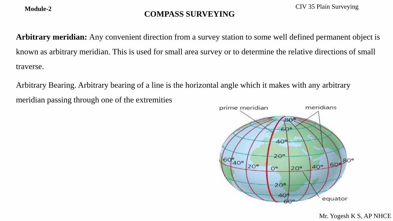
Arbitrary meridian: Any convenient direction from a survey station to some well defined permanent object is
known as arbitrary meridian. This is used for small area survey or to determine the relative directions of small
traverse.
Arbitrary Bearing. Arbitrary bearing of a line is the horizontal angle which it makes with any arbitrary
meridian passing through one of the extremities

CIV 35 Plain Surveying
Mr. Yogesh K S, AP NHCE
COMPASS SURVEYING Module-2
Common systems of notation of bearings:
1. Whole circle bearing (WBC) or Azimutal System.
2. Quadrantal bearing system (Q B)
Whole circle bearing (WBC) or Azimutal System:
In whole circle bearing (WCB) the bearing of a line at any point is measured with respect to a meridian. Its value varies
from zero to 360°, increasing in clockwise direction. Zero is north direction, 90° is east, 180° is south and 270° is west.
This type of bearing is used in prismatic compass.
Prismatic compass.

CIV 35 Plain Surveying
Mr. Yogesh K S, AP NHCE
COMPASS SURVEYING Module-2
Quadrantal bearing system (Q B):
In reduced bearing (RB) system, bearings are measured from north or south direction towards east or west. Hence, angles
are from 0 to 90°.
This system of measuring bearings is used in Surveyor’s compass and it is also known as Quadrantal Bearing (QB). The
bearing measured is designated with letter N or S in the beginning to indicate whether it is from north or south. The
letter E or W written after the angle indicates whether the bearing read is towards east or west, respectively

CIV 35 Plain Surveying
Mr. Yogesh K S, AP NHCE
COMPASS SURVEYING Module-2
Working through Prismatic compass.
1. Fixing the compass with tripod stand The tripod stand is placed at the required station with its legs well apart. Then the prismatic compass is held by the left hand and placed over the threaded top of the stand. After this, the compass box is turned clockwise by the right hand. Thus the threaded base of the compass box is fixed with the threaded top of the stand.
2. Centering: Normally, the compass is centred by dropping a piece of stone from the bottom of the compass box. Centring may also be done with the aid of a plumb bob held centrally below the compass box.
3. Levelling: Levelling is done with the help of a ball-and-socket arrangement provided on top of the tripod stand. This arrangement is loosened and the box is placed in such a way that the graduated ring rotates freely without touching either the bottom of the box or the glass cover on top.
Temporary adjustment of Prismatic compass.

CIV 35 Plain Surveying
Mr. Yogesh K S, AP NHCE
COMPASS SURVEYING Module-2
Working through Prismatic compass. (a) Compass Box The compass box is a circular metallic box (the metal should be non-magnetic) of diameter 8 to 10 cm. A pivot with a sharp point is provided at the centre of the box. (b) Magnetic Needle and Graduated Ring The magnetic needle is made of a broad, magnetised iron bar. The bar is pointed at both ends. The magnetic needle is attached to a graduated aluminium ring. The ring is graduated from 0° to 360° clockwise, and the graduations begin from the south end of the needle. Thus 0° is marked at the south, 90° at the west, 180° at the north and 270° at the east. (c) Sight Vane and Prism The sight vane and the reflecting prism are fixed diametrically opposite to the box. The sight vane is hinged with the metal box and consists of a horsehair at the centre. The prism consists of a sighting slit at the top and two small circular holes, one at the bottom of the prism and the other at the side of the observer's eye
(d) Dark Glasses Two dark glasses are provided with the prism. The red glass is meant for sighting luminous objects at night and the blue glass for reducing the strain on the observer's eye in bright daylight.

CIV 35 Plain Surveying
Mr. Yogesh K S, AP NHCE
COMPASS SURVEYING Module-2
Working through Prismatic compass.
(e) Adjustable Mirror A mirror is provided with the sight vane.
The mirror can be lowered or raised, and can also be inclined. If
any object is too low or too high with respect to the line of sight,
the minor can be adjusted to observe it through reflection.
(f) Brake Pin A brake pin is provided just at the base of the sight
vane. If pressed gently, it stops the oscillations of the ring.
(g) Lifting lever A lifting lever is provided just below the sight
vane. When the sight vane is folded, it presses the lifting pin. The
lifting pin then lifts the magnetic needle out of the pivot point to
prevent damage to the pivot head.

CIV 35 Plain Surveying
Mr. Yogesh K S, AP NHCE
COMPASS SURVEYING Module-2
Components of Surveyor’s compass. The Surveyor's compass:
The surveyor's compass is similar to the prismatic compass
except for the following points.
(a) There is no prism on it. Readings are taken with naked eye.
(b) It consists of an eye-vane (in place of prism) with a fine sight
slit.
(c) The graduated aluminium ring is attached to the circular box.
It is not fixed to the magnetic needle.
(d) The magnetic needle moves freely over the pivot. The needle
shows the reading on the graduated ring.
(e) The ring is graduated from 0° to 90° in four quadrants. 0° is
marked at the north and south, and 90° at the east and west.
The letters E (east) and W (west) are interchanged from their
true positions. The figures are written the right way up.
(f) No mirror is attached to the object vane.
CIV 35 Plain Surveying
Mr. Yogesh K S, AP NHCE
COMPASS SURVEYING Module-2

CIV 35 Plain Surveying
Mr. Yogesh K S, AP NHCE
COMPASS SURVEYING Module-2
MAGNETIC DECLINATION: Magnetic declination at a
place is the horizontal angle between the true meridian and
the magnetic meridian shown by the needle at the time of
observation.
• If the magnetic meridian is to the right side (or eastern
side) of the true meridian, declination is said to be
eastern or positive
• If it to be the left side (or western side). the declination is
said to be western or negative
CIV 35 Plain Surveying
Mr. Yogesh K S, AP NHCE
COMPASS SURVEYING Module-2
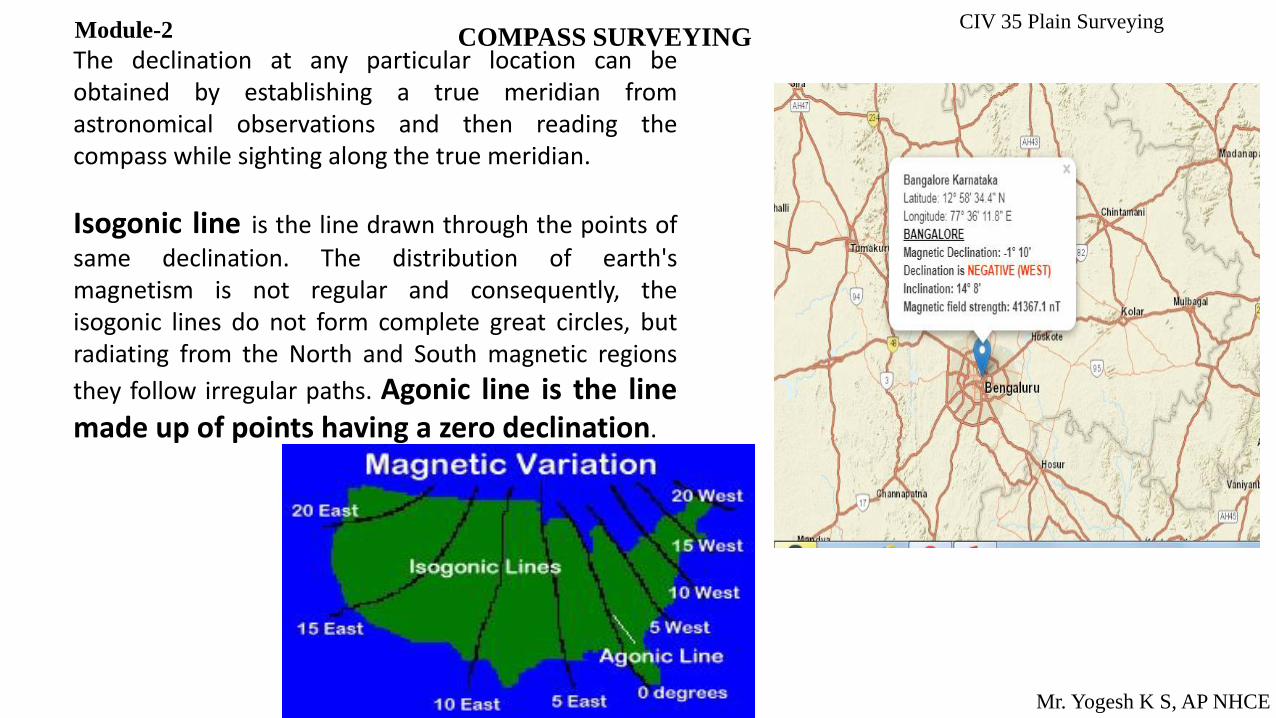
The declination at any particular location can be obtained by establishing a true meridian from astronomical observations and then reading the compass while sighting along the true meridian.
Isogonic line is the line drawn through the points of
same declination. The distribution of earth's magnetism is not regular and consequently, the isogonic lines do not form complete great circles, but radiating from the North and South magnetic regions
they follow irregular paths. Agonic line is the line made up of points having a zero declination.
CIV 35 Plain Surveying
Mr. Yogesh K S, AP NHCE
COMPASS SURVEYING
Local attraction:
While compass surveying, the magnetic needle is sometimes disturbed from its normal position under
the influence of external attractive forces. Such a disturbing influence is called as local attraction
Is the phenomenon by which the magnetic needle is constantly prevented to point towards the
magnetic north at a place. This is because that these magnetic compass is influenced by other
magnetic objects at that locality such as wires carrying electric current, rails, steel and iron
structures, steel tapes etc.
The occurrence of local attraction can be detected by observing the difference between the fore and
back bearings. If there is no influence of local attraction and other error, this difference will be 180.
So we can then conclude that both stations are free from local attraction.

CIV 35 Plain Surveying
Mr. Yogesh K S, AP NHCE
COMPASS SURVEYING
Elimination of local attraction in Compass Surveying:
Due to local attraction significant amount of error can occur in compass surveying observations and
they will be same on all the bearings.
Local attraction can be minimized using following methods:
Method 1 : This method is based on the difference of fore and back bearings. We already know that the
difference between fore and back bearing a line will be 180˚ if there is no errors in measurement. So
based on this error free observation of bearings, corrections for other lines can be calculated. However
if there is no two bearing has a difference of 180˚, we can calculate the correction from the mean value
of that bearings which may have least error.
CIV 35 Plain Surveying
Mr. Yogesh K S, AP NHCE
COMPASS SURVEYING
Elimination of local attraction in Compass Surveying:
Due to local attraction significant amount of error can be occur in compass surveying observations
and they will be same on all the bearings.
Local attraction can be minimized using following methods:
Method 2 : This method is more faster method for applying correction. This is based on the interior
angles of the closed traverse formed. The interior angles measured will be correct on the basis of the
fact that these angles are not affected by the local attraction whereas the stations are. So the sum of total
interior angles for a closed traverse will be (2n-4) 90˚.
If there is any error exists both sum will not be same. The total error can be distributed among the
angles equally because equal error will occur on each interior angle. So starting from the correct
observation of bearing which has a difference in fore and back bearing is 180˚, we can calculate all
other corrected bearings