planar drawings of higher-genus graphskobourov/genus.pdf · planar drawings of higher-genus graphs...
TRANSCRIPT

Planar Drawings of Higher-Genus Graphs
Christian A. Duncan1, Michael T. Goodrich2, and Stephen G. Kobourov3
1 Dept. of Computer Science, Louisiana Tech Univ.http://www.latech.edu/~duncan/
2 Dept. of Computer Science, Univ. of California, Irvinehttp://www.ics.uci.edu/~goodrich/
3 AT&T Research Labs, Florham Park, NJhttp://www.research.att.com/info/skobourov
Abstract. In this paper, we give polynomial-time algorithms that cantake a graph G with a given combinatorial embedding on a surface Sof genus g and produce a planar drawing of G in R2, with a boundingface defined by a polygonal schema P for S. Our drawings are planar,but they allow for multiple copies of vertices and edges on P’s boundary,which is a common way of visualizing higher-genus graphs in the plane.As a side note, we show that it is NP-complete to determine whether agiven graph embedded in a genus-g surface has a set of 2g fundamentalcycles with vertex-disjoint interiors, which would be desirable from agraph-drawing perspective.
1 IntroductionThe classic way of drawing a graph G = (V,E) in R2 involves associating eachvertex v in V with a unique point (xv, yv) in R2 and associating with eachedge (v, w) ∈ E an open Jordan curve in R2 that has (xv, yv) and (xw, yw) asits endpoints. If the curves associated with the edges in a classic drawing of Gintersect only at their endpoints, then (the embedding of) G is a plane graph.Graphs that admit plane graph representations are planar graphs, and therehas been a voluminous amount of work on algorithms on classic drawings ofplanar graphs Most notably, planar graphs can be drawn with vertices assignedto integer coordinates in an O(n) × O(n) grid, which is often a desired typeof classic drawing known as a grid drawing. Moreover, there are planar graphdrawings that use only straight line segments for edges [2, 11].
The beauty of plane graph drawings is that, by avoiding edge crossings, con-fusion and clutter in the drawing is minimized. Likewise, straight-line drawingsfurther improve graph visualization by allowing the eye to easily follow con-nections between adjacent vertices. In addition, grid drawings enforce a naturalseparation between vertices, which further improves readability. Thus, a “goldstandard” in classic drawings is to produce planar straight-line grid drawingsand, when that is not easily done, to produce planar grid drawings with edgesdrawn as simple polygonal chains.
Unfortunately, not all graphs are planar. So drawing them in the classic wayrequires some compromise in the gold standard for plane drawings. In particular,

any classic drawing of a non-planar graph must necessarily have edge crossings,and minimizing the number of such crossings in a non-planar graph is NP-hard [5].
One point of hope for improved drawings of non-planar graphs is to drawthem crossing-free on surfaces of higher genus, such as toruses, double toruses,or, in general, a surface topologically equivalent to a sphere with g handles,that is, a genus-g surface. Such drawings are called cellular embeddings or 2-cell embeddings, since they partition the genus-g surface into a collection ofcells that are topologically equivalent to disks. As in classic drawings of planargraphs, these cells are called faces, and it is easy to see that such a drawingwould avoid edge crossings.
In a fashion analogous to the case with planar graphs, cellular embeddings ofgraphs in a genus-g surface can be characterized combinatorially. In particular,it is enough if we just have a rotational order of the edges incident on eachvertex in a graph G to determine a combinatorial embedding of G on a surface(which has that ordering of associated curves listed counterclockwise aroundeach vertex). Such a set of orderings is called a rotation system and, since itgives us a combinatorial description of the set of faces, F , in the embedding,it gives us a way to determine the genus of the (orientable) surface that G isembedded into by using the Euler characteristic, |V |− |E|+ |F | = 2− 2g, whichalso implies that |E| is O(|V |+ g) [10].
Unfortunately, given a graph G, it is NP-hard to find the smallest g suchthat G has a combinatorial cellular embedding on a genus-g surface [12]. Thischallenge need not be a deal-breaker in practice, however, for there are heuris-tic algorithms for producing such combinatorial embeddings (that is, consistentrotation systems) [1]. Moreover, higher-genus graphs often come together withcombinatorial embeddings in practice, as in many computer graphics and meshgeneration applications.
In this paper, we assume that we are given a combinatorial embedding of agraph G on a genus-g surface, S, and are asked to produce a geometric drawingof G that respects the given rotation system. Motivated by the gold standardfor planar graph drawing and by the fact that computer screens and physicalprintouts are still primarily two-dimensional display surfaces, the approach wetake is to draw G in the plane rather than on some embedding of S in R3.
Making this choice of drawing paradigm, of course, requires that we “cut up”the genus-g surface, S, and “unfold” it so that the resulting sheet is topologicallyequivalent to a disk. The traditional method for performing such a cutting is witha canonical polygonal schema, P, which is a set of 2g cycles on S all containing acommon point, p, such that cutting S along these cycles results in a topologicaldisk. These cycles are fundamental in that each of them is a continuous closedcurve on S that cannot be retracted continuously to a point. Moreover, thesefundamental cycles can be paired up into complementary sets of cycles, (ai, bi),one for each handle, so that if we orient the sides of P, then a counterclockwiseordering of the sides of P can be listed as
a1b1a−11 b−1
1 a2b2a−12 b−1
2 a3b3a−13 b−1
3 . . . agbga−1g b−1
g ,
2

where a−1i (b−1
i ) is a reversely-oriented copy of ai, so that these two sides of Pare matched in orientation on S. Thus, the canonical polygonal schema for agenus-g surface S has 4g sides that are pairwise identified
Because we are interested in drawing the graph G and not just the topologyof S, it would be preferable if the fundamental cycles are also cycles in G inthe graph-theoretical sense. It would be ideal if these cycles form a canonicalpolygonal schema with no repeated vertices other than the common one. This isnot always possible [7] and furthermore, as we show in Appendix B, the prob-lem of finding a set of 2g fundamental cycles with vertex-disjoint interiors in acombinatorially embedded genus-g graph is NP-complete. There are two naturalchoices, both of which we explore in this paper:
– Draw G in a polygon P corresponding to a canonical polygonal schema, P,possibly with repeated vertices and edges on its boundary.
– Draw G in a polygon P corresponding to a polygonal schema, P, that is notcanonical.
In either case, the edges and vertices on the boundary of P are repeated (since we“cut” S along these edges and vertices). Thus, we need labels in our drawing ofG to identify the correspondences. Such planar drawings of G inside a polygonalschema P are called polygonal-schema drawings of G. There are three naturalaesthetic criteria such drawings should satisfy:
1. Straight-line edges: All the edges in a polygonal-schema drawing should berendered as polygonal chains, or straight-line edges, when possible.
2. Straight frame: Each edge of the polygonal schema should be rendered asa straight line segment, with the vertices and edges of the correspondingfundamental cycle, placed along this segment. We refer to such a polygonal-schema drawing as having a straight frame.
3. Polynomial area: Drawings should have polynomial area when they are nor-malized to an integer grid.
It is also possible to avoid repeated vertices and instead use a classic graphdrawing paradigm, by transforming the fundamental polygon rendering usingpolygonal-chain edges that run through “overpasses” and “underpasses” as inroad networks, so as to illustrate the topological structure of G; see Fig. 1.
Our Contributions. We provide several methods for producing planar polygonal-schema drawings of higher-genus graphs. In particular, we provide four algo-rithms, one for torodial (g = 1) graphs and three for non-toroidal (g > 1) graphs.Our algorithm for toroidal graphs simultaneously achieves the three aestheticcriteria for polygonal schema drawings: it uses straight-line edges, a straightframe, and polynomial area. The three algorithms for non-toroidal graphs, Peel-and-Bend, Peel-and-Stretch, and Peel-and-Place, achieve two of the tree aestheticcriteria, and differ in which criteria they fail to meet.
3

Fig. 1. First row: Canonical polygonal schemas for graphs of genus one, two and four.Second row: Unrolling the high genus graphs with the aid of the overpasses and underpasses.
2 Finding Polygonal SchemasSuppose we are given a graph G together with its cellular embedding in a genus-g surface, S. An important first step in all of our algorithms involves our findinga polygonal schema, P, for G, that is, a set of cycles in G such that cutting Salong these cycles results in a topological disk. We refer to this as the Peel step,since it involves cutting the surface S until it becomes topologically equivalentto a disk. Since these cycles form the sides of the fundamental polygon we willbe using as the outer face in our drawing of G, it is desirable that these cyclesbe as “nice” as possible with respect to drawing aesthetics.
2.1 Trade-offs for Finding Polygonal Schemas
Unfortunately, some desirable properties are not effectively achievable. As Lazaruset al. [7] show, it is not always possible to have a canonical polygonal schema Psuch that each fundamental cycle in P has a distinct set of vertices in its interior(recall that the interior of a fundamental cycle is the set of vertices distinct fromthe common vertex shared with its complementary fundamental cycle—with thisvertex forming a corner of a polygonal schema). In addition, we show in the ap-pendix that finding a vertex-disjoint set of fundamental cycles is NP-complete.So, from a practical point of view, we have two choices with respect to methodsfor finding polygonal schemas.
Finding a Canonical Polygonal Schema. As mentioned above, a canonicalpolygon schema of a graph G 2-cell embedded in a surface of genus g consistsof 4g sides, which correspond to 2g fundamental cycles all containing a common
4

vertex. Lazarus et al. [7] show that one can find such a schema for G in O(gn)time and with total size O(gn), and they show that this bound is within aconstant factor of optimal in the worst case, where n is the total combinatorialcomplexity of G (vertices, edges, and faces), which is O(|V |+ g).
Minimizing the Number of Boundary Vertices in a Polygonal Schema.Another optimization would be to minimize the number of vertices in the bound-ary of a polygonal schema. Erikson and Har-Peled [4] show that this problem isNP-hard, but they provide an O(log2 g)-approximation algorithm that runs inO(g2n log n) time, and they give an exact algorithm that runs in O(nO(g)) time.
In our Peel step, we assume that we use one of these two optimization criteriato find a polygonal schema, which either optimizes its number of sides to be 4g,as in the canonical case, or optimizes the number of vertices on its boundary,which will be O(gn) in the worst case either way. Nevertheless, for the sake ofconcreteness, we often describe our algorithms assuming we are given a canonicalpolygonal schema. It is straight-forward to adapting these algorithms for non-canonical schemas.
2.2 Constructing Chord-Free Polygonal Schemas
In all of our algorithms the first step, Peel, constructs a polygonal schema ofthe input graph G. In fact, we need a polygonal schema, P, in which there isno chord connecting two vertices on the same side of P. Here we show how totransform any polygonal schema into a chord-free polygonal schema.
In the Peel step, we cut the graph G along a canonical set of 2g fundamentalcycles getting two copies of the cycle in G∗, the resulting planar graph. For eachof the two pairs of every fundamental cycle there may be chords. If the chordconnects two vertices that are in different copies of the cycle in G∗ then this isa chord that can be drawn with a straight-line edge and hence does not createa problem. However, if the chord connects two vertices in the same copy of thecycle in G∗, then we will not be able to place all the vertices of that cycle ona straight-line segment; see Figure 2(a). We show next that a new chord-freepolygonal schema can be efficiently determined from the original schema.
Theorem 1. Given a graph G combinatorially embedded in a genus-g surfaceand a canonical polygonal schema P on G with a common vertex p, a chord-freepolygonal schema P∗ can be found in O(gn) time.
Proof. We first use the polygonal schema to cut the embedding of G into atopological disk; see Fig. 2(a). Notice this cutting will cause certain vertices tobe split into multiple vertices. For each fundamental cycle in ci ∈ P, we stitchthe disk graph back together along this cycle forming a topological cylinder. Theouter edges (left and right) of the cylinder along this stitch will have two copiesof the vertex p, say p1 and p2. We perform a shortest path search from p1 top2. This path becomes our new fundamental cycle c∗i , (since p1 and p2 are thesame vertex in G). Observe that this cycle must be chord-free or else the pathchosen was not the shortest path; see Fig. 2(b). We then cut the cylinder along
5

c∗i and proceed to ci+1. The resulting set, P∗ = {c∗1, c∗2, . . . , c∗2g}, is therefore acollection of chord-free fundamental cycles all sharing the common vertex p. ut
It should be noted that, although each cycle c∗i is at the time of its creationa shortest path from the two copies of p, these cycles are not the shortest funda-mental cycles possible. For example, a change in the cycle of ci+1 could introducea shorter possible path for c∗i , but not additional chords.
(a) (b)
Fig. 2. (a) A graph embedded on the torus that has been cut into a topological disk usingthe cycles 1, 2, 3 and 1, 4, 7, 8, 11, 13, 15 with chord (4, 8). The grey nodes correspond tothe identical vertices above. The highlighted path represents a shortest path between thetwo copies of vertex 1. (b) The topological disk after cutting along this new fundamentalcycle. The grey nodes show the old fundamental cycle.
3 Straight Frame and Polynomial AreaIn this section, we describe our algorithms that construct a drawing of G in astraight frame using polynomial area. Here we are given an embedded genus-g graph G = (V,E) along with a chord-free polygonal schema, P, for G fromthe Peel step. We rely on a modified version of the algorithm of de Fraysseix,Pach and Pollack [2] for the drawing. Sections 3.1 and 3.2 describe the details forg = 1 and for g > 1, respectively. In the latter case we introduce up to O(k) edgeswith single bends where k is the number of vertices on the fundamental cycles.Thus, we refer to the algorithm for non-toroidal graphs as the Peel-and-Bendalgorithm.
3.1 Grid Embedding of Toroidal Graphs
For toroidal graphs we are able to achieve all three aesthetic criteria: straight-lineedges, straight frame, and polynomial area.
Theorem 2. Let G∗ be an embedded planar graph and P = {P1, P2, . . . , P4g}in G∗ be a collection of 4g paths such that each path Pi = {pi,1, pi,2, . . . , pi,ki
} ischord-free, the last vertex of each path matches the first vertex of the next path,and when treated as a single cycle, P forms the external face of G∗. If g = 1,
6

we can in linear time draw G∗ on an O(n)×O(n2) grid with straight-line edgesand no crossings in such a way that for each path Pi on the external face thevertices on that path form a straight line.
Proof. For simplicity, we assume that every face is a triangle, except for theouter face (extra edges can be added and later removed). The algorithm ofde Fraysseix, Pach and Pollack (dPP) [2] does not directly solve our problembecause of the addtional requirement for the drawing of the external face. In thecase of g = 1, the additional requirement is that the graph must be drawn sothat the external face forms a rectangle, with P1 and P3 as the top and bottomhorizontal boundaries and P2 and P4 as the right and left boundaries.
Recall that the dPP algorithm computes a canonical labeling of the verticesof the input graph and inserts them one at a time in that order while ensuringthat when a new vertex is introduced it can “see” all of its already insertedneighbors. One technical difficulty lies in the proper placement of the top row ofvertices. Due to the nature of the canonical order, we cannot force the top rowof vertices to all be the last set of vertices inserted, unlike the bottom row whichcan be the first set inserted. Consequently, we propose an approach similar tothat of Miura, Nakano, and Nishizeki [9]. First, we split the graph into two parts(not necessarily of equal size), perform a modified embedding on both pieces,invert one of the two pieces, and stitch the two pieces together.
Lemma 1. Given an embedded plane graph G that is fully triangulated exceptfor the external face and two edges el and er on that external face, it is possiblein linear time to partition V (G) into two subsets V1 and V2 such that
1. the subgraphs of G induced by V1 and V2, called G1 and G2, are both con-nected subgraphs;
2. for edge el = (ul, vl), ul ∈ V1 and vl ∈ V2 and the same for edge er; and3. the union U of the set of faces in G that are not in G1 or G2 forms an
outerplane graph with the property that the external face of U is a cycle withno repeated vertices.
Proof. First, we compute the dual D of G, where each face in (the primal graph)G is a node inD and there is an arc between two nodes inD if their correspondingprimal faces share an edge in common. We ignore the external face in this step.For clarity we shall refer to vertices and edges in the primal and nodes and arcsin the dual. Note that for any edge on the external cycle, there is exactly onecorresponding node in D whereas all other edges have two corresponding nodesin D (the two neighboring faces sharing that edge). In addition, for any node inthe dual there are three corresponding vertices in the primal; see Fig. 3(a).
We further augment the dual by adding an arc between two nodes in D ifthey also share a vertex in common. Call this augmented dual graph D∗.
Let the source node s be the node corresponding to the edge el and the sinknode t be the node corresponding to the edge er. We then perform a breadth-firstshortest-path traversal from s to t on D∗; see Fig. 3(b).
7

(a) (b)
(c) (d)
Fig. 3. (a) A graph G and its dual D. The dark edges/nodes represent the sink and sourcenodes. (b) Each dual node is labeled with its distance (in D∗) from the start node 0. Ashortest path p∗ is drawn with thick dark arcs. This path includes the augmented arcsof D∗. (c) The path p formed after expanding the augmented arcs. The edges from theprimal that are cut by this path are shown faded. (d) The two sets V1 (light vertices) andV2 (darker vertices) formed by the removal of path p. The external face of U is defined bythe thick edges along with the edges (1, 2) and (3, 4).
Let p∗ be a shortest (augmented) path in D∗ obtained by this search. Wenow create a (regular) path p by expanding the augmented arcs added. Thatis, if there is an arc (u, v) ∈ p∗ such that u and v share a common vertex in Gbut not a common edge in G, i.e. they are part of a fan around the commonvertex, we add back the regular arcs from u to v adjacent to this common vertex.The choice of going clockwise or counter-clockwise around the common vertexis arbitrary; see Fig. 3(c).
First, observe that although p is no longer the shortest possible path in D,it is still necessarily acyclic and so no node in D is visited more than once.Additionally, no vertex in the primal is visited by more than one consecutivesequence of nodes in the path. That is, if two nodes u and v in p share a commonvertex in the primal then all nodes between u and v in p also share a commonvertex. To see why, assume not. Then in p∗ there would have been two nodesu and v that shared a common vertex that visited at least one other node wbetween them. But since the distance between u and v in D∗ is one, p∗ couldnot be a shortest path.
8
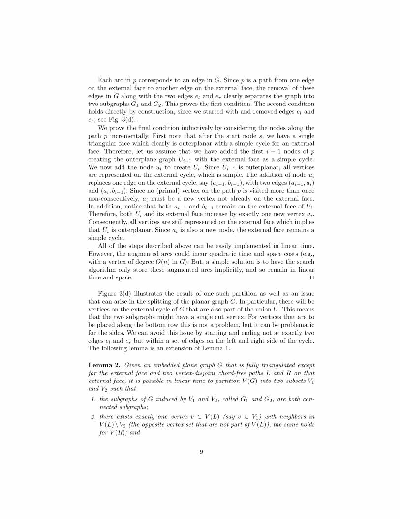
Each arc in p corresponds to an edge in G. Since p is a path from one edgeon the external face to another edge on the external face, the removal of theseedges in G along with the two edges el and er clearly separates the graph intotwo subgraphs G1 and G2. This proves the first condition. The second conditionholds directly by construction, since we started with and removed edges el ander; see Fig. 3(d).
We prove the final condition inductively by considering the nodes along thepath p incrementally. First note that after the start node s, we have a singletriangular face which clearly is outerplanar with a simple cycle for an externalface. Therefore, let us assume that we have added the first i − 1 nodes of pcreating the outerplane graph Ui−1 with the external face as a simple cycle.We now add the node ui to create Ui. Since Ui−1 is outerplanar, all verticesare represented on the external cycle, which is simple. The addition of node ui
replaces one edge on the external cycle, say (ai−1, bi−1), with two edges (ai−1, ai)and (ai, bi−1). Since no (primal) vertex on the path p is visited more than oncenon-consecutively, ai must be a new vertex not already on the external face.In addition, notice that both ai−1 and bi−1 remain on the external face of Ui.Therefore, both Ui and its external face increase by exactly one new vertex ai.Consequently, all vertices are still represented on the external face which impliesthat Ui is outerplanar. Since ai is also a new node, the external face remains asimple cycle.
All of the steps described above can be easily implemented in linear time.However, the augmented arcs could incur quadratic time and space costs (e.g.,with a vertex of degree O(n) in G). But, a simple solution is to have the searchalgorithm only store these augmented arcs implicitly, and so remain in lineartime and space. ut
Figure 3(d) illustrates the result of one such partition as well as an issuethat can arise in the splitting of the planar graph G. In particular, there will bevertices on the external cycle of G that are also part of the union U . This meansthat the two subgraphs might have a single cut vertex. For vertices that are tobe placed along the bottom row this is not a problem, but it can be problematicfor the sides. We can avoid this issue by starting and ending not at exactly twoedges el and er but within a set of edges on the left and right side of the cycle.The following lemma is an extension of Lemma 1.
Lemma 2. Given an embedded plane graph G that is fully triangulated exceptfor the external face and two vertex-disjoint chord-free paths L and R on thatexternal face, it is possible in linear time to partition V (G) into two subsets V1
and V2 such that
1. the subgraphs of G induced by V1 and V2, called G1 and G2, are both con-nected subgraphs;
2. there exists exactly one vertex v ∈ V (L) (say v ∈ V1) with neighbors inV (L) \V2 (the opposite vertex set that are not part of V (L)), the same holdsfor V (R); and
9

3. the union U of the set of faces in G that are not in G1 or G2 forms anouterplane graph with the property that the external face of U is a cycle withno repeated vertices.
Proof. The proof is a simple modification of the graph and proof of Lemma 1.First, let V (L) = v1, v2, . . . , vk be the ordered set of vertices in the path of L.We add an edge el = (v1, vk) on the external face. We do the same for the setR creating an edge er. We then proceed as with Lemma 1 with one additionalcaveat. We do not add augmented arcs between two nodes a and b that sharea common vertex v (part of a fan), if v is not part of L and the actual edgestraversed along the fan from a to b contains a vertex in L We do the same forR.
To see that the new condition is met, we claim that at most two (neighboring)vertices vi and vi+1 on L are involved in a cut along the path p∗. Assume anothervertex vj on L is involved in a cut, say on an arc leading to node a, later in thepath traversal, there would have been a shorter path to a since there is a directarc from the source to that node (both s and a share vj in common). Thiscontradicts the fact that p∗ was the shortest path chosen. If, however, vj is partof the augmented arc that includes vi and vi+1, once the arc is expanded, then wewould have had an edge to vj that was a chord, as it would have shared a vertexin common with either vi or vi+1 for which it was not adjacent to on the externalcycle. This contradicts our initial condition that the path L is chord-free.
Therefore there are at most two vertices vi and vi+1 with neighboring verticeson the opposite vertex set with, of course, vi and vi+1 being on opposite vertexsets themselves. The same argument holds for R. ut
We can now discuss the steps for the grid drawing of the genus-1 graphG∗ with an external face formed by P. Using Lemma 2, with L = P4 andR = P2, divide G∗ into two subgraphs G1 and G2. We proceed to embed G1
with G2 being symmetric. Assume without loss of generality that G1 containsthe bottom path, P3. Compute a canonical order of G1 so that the vertices ofP3 are the last vertices removed. Place all of the vertices of P3 on a horizontalline, p3,k3 , p3,k3−1, . . . , p3,1 placed consecutively on y = 0. This is possible sincethere are no edges between them (because the path is chord-free). Recall thatthe standard dPP algorithm maintains the invariant that at the start of eachiteration, the current external face consists of the original horizontal line and aset of line segments of slope ±1 between consecutive vertices. We modify thiscondition by requiring that the vertices on the right and left boundary that arepart of P2 and P4 be aligned vertically and that the current external face mighthave horizontal slopes corresponding to vertices from P3; see Fig. 4(a). Uponinsertion of a new vertex v, the vertex will have consecutive neighboring verticeson the external face. We label the left and rightmost neighbors x` and xr. Toachieve our modified invariant, we insert a vertex v into the current drawingdepending on its type, 0,1, or 2, as follows:– (Type 0) Vertices not belonging to a path in P are inserted as with the
traditional dPP algorithm. This insertion might require up to two horizontalshifts; see Fig. 4(a).
10

– (Type 1) Vertices belonging to P2, which must be placed vertically alongthe right boundary, are inserted with a line segment of slope +1 between x`
and v and a vertical line segment between v and xr. Notice that xr mustalso be in P2. And because P2 is chord-free xr is the topmost vertex on theright side of the current external face. That is, v can see xr. By Lemma 2and the fact that the graph was fully triangulated, we also know that v musthave a vertex x`. This insertion requires only 1 shift, for the visibility of x`
and v. Again the remaining vertices x`+1, . . . , xr−1 are connected as usual;see Fig. 4(b).
– (Type 2) Vertices belonging to P4, which must be placed vertically alongthe left boundary, are handled similarly to Type 1.
Because of Lemma 2, after processing both G1 and G2, we can proceed to stitchthe two portions together; see Fig. 4(c). Shift the left wall of the narrower graphsufficiently to match the width of the other graph. For simplicity, refer to thevertices on the external face of each subgraph that are not exclusively part of thewall or bottom row as upper external vertices. For each subgraph, considerthe point p located at the intersection of the lines of slope ±1 extending fromthe left and rightmost external vertices. Flip G2 vertically placing it so that itspoint p lies either on or just above (in case of non-integer intersection) G1’spoint. Because the edges between the upper external vertices have slope |m| ≤ 1and because of the vertical separation of the two subgraphs, every upper externalvertex on G1 can directly see every upper external vertex on G2. By Lemma 2,we know that the set of edges removed in the separation along with the edgesconnecting the upper external vertices forms an outerplanar graph. Therefore, wecan reconnect the removed edges, joining the two subgraphs, without introducingany crossings.
We claim that the area of this grid is O(n) × O(n2). First, let us analyzethe width. From our discussion, we have accounted for each insertion step usingshifts. Since the maximum amount of shifting of 2 units is done with Type0 vertices, we know that each of the two subgraphs has width at most 2n.In addition, the stitching stage only required a shifting of the smaller widthsubgraph. Therefore, the width of our drawing is at most 2n. Ideally, the heightof our drawing would also match this bound. The stitching stage for exampleonly adds at most W ≤ 2n units to the final height. However, as Figure 5illustrates in the appendix, a problem arises when vertices of Type 1 and Type2 interconnect. Normally, after completion the height is a simple function of halfthe width, because the edges have slopes ±1. We can only say this about theupper vertices. However, after the insertion of each wall vertex we know thatthe height increases by at most W . Therefore, we know that the height is atmost Wn or 2n2 and consequently we have a correct drawing using a grid of sizeO(n)×O(n2). ut
Thus, we get a planar polygonal-schema drawing of a torodial graph G in arectangle, which simultaneously achieves polynomial area, a straight frame, andstraight-line edges.
11

(a) (b) (c)
Fig. 4. (a) The embedding process after insertion of the first 11 vertices and the subsequentinsertion of a Type 0 vertex with v = 12, x` = 2, and xr = 11. Note the invariant conditionallowing the two partial vertical walls {8, 7, 5} ⊂ P2 and {1, 9, 10} ⊂ P4. The lightly shadedvertices to the right of 12 including xr have been shifted over one unit. (b) The result ofinserting a Type 1 vertex with v = 13, x` = 2, and xr = 8. Note, the lightly shaded verticesto the left of and including x` = 2 are shifted over one unit. (c) Two subgraphs G1 andG2 stitched together, the thicker edges are the edges initially removed in the separationphase. Note, although p can be used as the point of placement, as this example illustrates,it is possible to compress the stitch further.
3.2 The Peel-and-Bend Algorithm
The case for g > 1 is similar, but involves a few alterations. First, we use n = |V |unlike the previous sections which used n = |V |+ g. The main difference, how-ever, is that we cannot embed the outer face using only horizontal and verticalwalls unless the fundamental cycles are chord-free or unless edge bends are al-lowed. Since we desire a straight-frame rendering of the polygonal schema P ina rectangle, we must allow some edge bends in this case. The following theo-rem describes our resulting drawing method, which we call the Peel-and-Bendalgorithm.
Theorem 3. Let G∗ be an embedded planar graph and P = {P1, P2, . . . , P4g}in G∗ be a collection of 4g paths such that each path Pi = {pi,1, pi,2, . . . , pi,ki}is chord-free, the last vertex of each path matches the first vertex of the nextpath, and when treated as a single cycle, P forms the external face of G∗. Letk =
∑4gi=1(ki − 1) be the number of vertices on the external cycle. We can draw
G∗ on an O(n) × O(n2) grid with straight-line edges and no crossings and atmost k− 3 single-bend edges in such a way that for each path Pi on the externalface the vertices on that path form a straight line.
Proof. First, let us assume that the entire external face, represented by P, iscompletely chord-free. That is, if two vertices on the external cycle share anedge then they are adjacent on the cycle. In this case we can create a new set of4 paths, P ′ = {P1,∪i=2,...,2gPi, P2g+1,∪i=2g+2,4gPi}.We can then use Theorem 2to prove our claim using no bends.
If, however, there exist chords on the external face, embedding the graphwith straight-lines becomes problematic, and in fact impossible to do using a
12

rectangular outer face. By introducing a temporary bend vertex for each chordand retriangulating the two neighboring faces, we can make the external facechord free. Clearly this addition can be done in linear time. Since there are atmost k vertices on the external face and since the graph is planar, there areno more than k − 3 such bend points to add. We then proceed as before usingTheorem 2, subsequently replacing inserted vertices with a bend point. ut
4 Algorithms for Non-Toroidal GraphsIn this section, we describe two more algorithms for producing a planar polygonal-schema drawing of a non-toroidal graph G, which is given together with its com-binatorial embedding in a genus-g surface, S, where g > 1. As mentioned above,these algorithms provide alternative trade-offs with respect to the three primaryaesthetic criteria we desire for polygonal-schema drawings. For the sake of space,we describe these algorithms at a very high level and leave their details and fullanalysis to the final version of this paper.
The Peel-and-Stretch Algorithm. In the Peel-and-Stretch Algorithm, wefind a chord-free polygonal schema P for G and cut G along these edges toform a planar graph G∗. We then layout the sides of P in a straight-framemanner as a regular convex polygon, with the vertices along each boundaryedge spaced as evenly as possible. We then fix this as the outer face of G∗ andapply Tutte’s algorithm [13, 14] to construct a straight-line drawing of the restof G∗. This algorithm therefore achieves a drawing with straight-line edges in a(regular) straight frame, but it may require exponential area when normalizedto an integer grid, since Tutte’s drawing algorithm may generate vertices withcoordinates that require Θ(n log n) bits to represent.
The Peel-and-Place Algorithm. In the Peel-and-Place Algorithm, we startby finding a polygonal schema P for G and cut G along these edges to forma planar graph G∗, as in all our algorithms. In this case, we then create a newtriangular face, T , and place G∗ in the interior of T , and we fully triangulate thisgraph. We then apply the planar drawing algorithm of Schnyder [11] to constructa drawing of this graph in an O(n)×O(n) integer grid with straight-line edges.Finally, we remove all extra edges to produce a polygonal schema drawing of G.The result will be a polygonal-schema drawing with straight-line edges havingpolynomial area, but there is no guarantee that it is a straight-frame drawing,since Schnyder’s drawing algorithm makes no collinear guarantees for verticesadjacent to the vertices on the bounding triangle.
5 Conclusion and Future WorkIn this paper, we present several algorithms for polygonal-schema drawings ofhigher-genus graphs. Our method for toroidal graphs achieves drawings that si-multaneously use straight-line edges in a straight frame and polynomial area.Previous algorithms for the torus were restricted to special cases or did not
13

always produce polygonal-schema renderings [3, 6, 15]. Our methods for non-toroidal graphs can achieve any two of these three criteria. It is an open prob-lem whether it is possible to achieve all three of these aesthetic criteria fornon-toroidal graphs. To the best of our knowledge, previous algorithms for gen-eral graphs in genus-g surfaces were restricted to those with “nice” polygonalschemas [16].
References1. J. Chen, S. P. Kanchi, and A. Kanevsky. A note on approximating graph genus.
Information Processing Letters, 61(6):317 – 322, 1997.2. H. de Fraysseix, J. Pach, and R. Pollack. How to draw a planar graph on a grid.
Combinatorica, 10(1):41–51, 1990.3. D. Eppstein. The topology of bendless three-dimensional orthogonal graph draw-
ing. In Graph Drawing: 16th Int. Symp. (GD 2008), pages 78–89, 2009.4. J. Erickson and S. Har-Peled. Optimally cutting a surface into a disk. In Proc. of
the 18th ACM Symp. on Computational Geometry (SCG), pages 244–253, 2002.5. M. R. Garey and D. S. Johnson. Crossing number is NP-complete. SIAM J.
Algebraic Discrete Methods, 4(3):312–316, 1983.6. W. Kocay, D. Neilson, and R. Szypowski. Drawing graphs on the torus. Ars
Combinatoria, 59:259–277, 2001.7. F. Lazarus, M. Pocchiola, G. Vegter, and A. Verroust. Computing a canonical
polygonal schema of an orientable triangulated surface. In Proc. of the 17th ACMSymp. on Computational Geometry (SCG), pages 80–89, 2001.
8. M. Middendorf and F. Pfeiffer. On the complexity of the disjoint paths problem.Combinatorica, 13(1):97–107, 1993.
9. K. Miura, S.-I. Nakano, and T. Nishizeki. Grid drawings of 4-connected planegraphs. Discrete and Computational Geometry, 26(1):73–87, 2001.
10. B. Mohar and C. Thomassen. Graphs on Surfaces. Johns Hopkins University Press,2001.
11. W. Schnyder. Embedding planar graphs on the grid. In Proceedings of the 1stACM-SIAM Symposium on Discrete Algorithms (SODA), pages 138–148, 1990.
12. C. Thomassen. The graph genus problem is NP-complete. J. Algorithms,10(4):568–576, 1989.
13. W. T. Tutte. Convex representations of graphs. Proceedings London MathematicalSociety, 10(38):304–320, 1960.
14. W. T. Tutte. How to draw a graph. Proc. London Math. Society, 13(52):743–768,1963.
15. A. Vodopivec. On embeddings of snarks in the torus. Discrete Mathematics,308(10):1847–1849, 2008.
16. A. Zitnik. Drawing graphs on surfaces. SIAM J. Disc. Math., 7(4):593–597, 1994.
14

A Description of Quadratic HeightIn this section, we consider the grid area required by our algorithm for drawingtoroidal graphs from Section 3.1. Specifically, we show that the O(n) × O(n2)area is tight if we insist on straight-line edges and a straight frame drawing; seeFig. 5. In particular, let the width at the start of an iteration be W . If we adda vertex v on the left wall that is connected to a vertex on the right wall, thenthis vertex must be inserted at a height W above the vertex on the right wall,to maintain proper slope. Repeating this, leads to a height of the grid that isquadrating in the width of the grid. As the underlying dPP algorithm requireswidth linear in the number of vertices in the graph, we get the O(n) × O(n2)area.
Fig. 5. Two examples forcing a height that grows quadratically, as our method is currentlydescribed. A relaxation of the slope constraints could resolve this issue.
B Finding Simple Fundamental Cycles is NP-Complete
In this section, we prove the following:
Theorem 4. Given a graph G combinatorially embedded in a genus-g surface,it is NP-complete to find a set of 2g fundamental cycles with vertex-disjointinteriors.
Proof. It is easy to see that this problem is NP—just guess a set of 2g cyclesand test that they are fundamental cycles with vertex-disjoint interiors.
15

G’
e
v
wG’
v
w
Fig. 6. Replacing each edge in S with Ge, which is K5 minus one edge.
To complete the proof, we observe that there is a simple reduction from thefollowing NP-complete problem [8]:– Disjoint Paths for Planar Graphs with Maximum Degree 3 (DPP3):
Given a planar graph G and a disjoint set S of the edges in G, determine ifthere is a set of vertex-disjoint cycles in G that contains each of the edgesof S.
Suppose, then, that we are given an instance of the DPP3 problem. We begin byremoving all the edges in S from G, giving the subgraph G′, and checking, foreach edge e = (v, w) in S, if w is reachable from v. If any such test fails, then theanswer to the DPP3 problem is “no.” So, let us suppose each such endvertex isreachable from its partner. Then, for each e = (v, w) in S, we connect v and wwith a subgraph, Ge, which is a copy of K5 minus one edge, oriented as shownin Fig. 6. Let G denote G′ with the subgraph Ge added for each edge e in S,and note that G is embedded in a surface of genus |S|.
So, suppose that the DPP3 problem is solvable in G. Then we can form aset of 2|S| fundamental cycles with vertex-disjoint interiors, by taking, for eachedge e = (v, w) in S, the path from v to w in G′ plus a path from w to v in Ge,and we can form its complementary fundamental cycle, say, by taking the cycleformed by the vertices in Ge adjacent to v.
Suppose, instead, that we can form a set of 2|S| vertex-disjoint fundamentalcycles in G. Note that, since w is reachable from v in G′, for each e = (v, w) in S,each Ge requires a handle in the embedding of G in a surface of genus |S|. That is,G′ is essentially providing the missing edge inK5 and the edges ofGe are orientedto require a handle here. Moreover, by the construction, one fundamental cyclemust include only vertices in Ge, since Ge forms a biconnected component inG. In addition, since Ge does not itself contain two complementary fundamentalcycles, the complementary fundamental cycle to the one in Ge must be formedby a path from v to w in G. Therefore, if all the fundamental cycles in G havevertex-disjoint interiors, then the paths in G connecting the ends of each edge inS must be vertex disjoint. Moreover, since each Ge is a biconnected componentin G, these paths must lie entirely in G′. Thus, replacing each subgraph Ge
with the associated edge e in S gives us a set of |S| vertex-disjoint cycles in Gcontaining each edge in S. ut
16