plan review checklist-2015 international residential code · plan review checklist-2015...
TRANSCRIPT

1
Plan Review Checklist-2015 International Residential Code1. CONSTRUCTION DOCUMENTS & COMPLIANCE
TO APPROVED PLANS : IRC Section R106.
( 1 ) Approved site plans shall be attached to the approved
building plans during inspection. (2) Property lines shall
be marked. (3) Setback distances will be measured from
the furthest projection of the permitted structure.
( 3 ) M anufacturer’s installation instructions shall be
available on the job site at the time of inspection. (4)All
work shall be installed in accordance with the approved
construction documents. (5) Any changes made during
construction that are not in compliance with the approved
construction documents shall be resubmitted for approval
as an amended set of construction documents. To request
approval of revisions complete a “Request to Revise
Approved Plan” application and submit to the Mason
County Permit Center along with approved plans and
documents detailing the proposed changes.
2. EGRESS WINDOWS: . IRC Section R311. All sleeping
rooms and basements with habitable space shall have at
least one open able emergency escape and rescue opening.
Such opening shall open directly into a public street,
public alley, yard or court. Emergency escape and rescue
openings shall have a minimum net clear opening of 5.7
square feet. Except that grade floor openings shall have a
minimum net clear opening of 5 square feet (see definition
below). The minimum net clear opening height dimension
shall be 24". The minimum net clear opening width
dimension shall be 20". The openings shall have a
maximum height of not more than 44" measured from
the finished floor to the bottom of the clear opening.
Emergency escape and rescue openings shall be
operational from the inside of the room without use of
keys or tools or special knowledge. Window wells shall be
provided when egress windows have a finished sill height
below adjacent ground elevation. The well shall allow the
window to be fully opened and provide a minimum
horizontal area of 9 sq. ft, with a minimum horizontal
projection and width of 36-inches. Window wells with a
vertical depth of more than 44" shall be equipped with a
permanent ladder. Grade floor opening definition: A
window or other opening located such that the sill height
of the opening is not more than 44” above or below the
finished ground level adjacent to the opening. Refer to
handout for additional information
3. SMOKE & CARBON MONOXIDE ALARMS: IRC
Section R314 & WAC R315. All smoke alarms shall be
listed in accordance with UL217 and installed in
accordance with the provisions of the International
Residential Code and the household warning equipment
provisions of NFPA 72. Smoke alarms shall be installed in
each sleeping room, outside each separate sleeping area in
the immediate vicinity of the bedrooms, in napping areas of
family child daycare homes, on each additional story of the
dwelling including basements and habitable attics. Each
story including basements and habitable attics shall have at
least one detector. When more than one smoke alarm is
required to be installed the alarm devices shall
be interconnected in such a manner that the actuation of one
alarm will activate all of the alarms in the individual unit. The
alarm shall be clearly audible in all bedrooms over
background noise levels with all intervening doors closed.
Required smoke alarms shall receive their primary power
from the building wiring when such wiring is served from a
commercial source and when primary power is interrupted,
shall receive power from a battery. Additions, interior
alterations, and repairs shall be provided with smoke alarms
as required for new dwellings; the smoke alarms shall be
interconnected and hard wired. Exception: Smoke alarms are
not required to be interconnected and hardwired where the
alteration or repairs does not result in the removal of interior
wall or ceiling finishes exposing the structure, unless there is
an attic, crawl space, or basement available which could
provide access for hard wiring and interconnection without
removal of hard finishes. Repairs to the exterior surfaces of
dwellings are exempt from these requirements.
Carbon monoxide alarms are required in new residential
construction, where dwelling has either or both of the
following conditions exist (1) the dwelling contains a fuel-
fired appliance. (2) the dwelling has an attached garage with
an opening that communicates with the residence. Carbon
monoxide alarms shall be listed in accordance with UL 2034.
Combination carbon monoxide and smoke alarms shall be
listed in accordance with UL 2034 and UL 217. Detectors
shall be installed outside of each separate sleeping room in
the immediate vicinity outside of the bedroom in the dwelling
and on each level of the dwelling in accordance with
manufacturer’s specifications. Where a fuel burning
appliance is located within a bedroom or its attached
bathroom, a carbon monoxide alarm shall be installed
within the bedroom.
4. SAFETY GLAZING : R308.1 Each pane of glass
installed in a hazardous location shall be provided with a
manufacturer’s designation specifying who applied the
designation, designating the type of glass and the safety
glazing standard. The designation shall be visible in the
final installation and shall be acid etched, sand-blasted,
ceramic fired, laser etched, embossed or on that cannot be
removed without being destroyed.
R308.4.1 Hazardous locations. The following shall be
considered specific hazardous locations for the purposes of
glazing:
Glazing in all fixed and operable panels of swinging,
sliding and bi-fold doors.
Exceptions:
Glazed openings of a size through which a 3-inch
diameter (76 mm) sphere is unable to pass.
Decorative glazing.
R308.4.2. Glazing in an individual fixed or operable panel
adjacent to a door shall be considered to be a hazardous
location where the bottom exposed edge of the glazing is
less then 60 inches above the floor or walking surface and

2
it meets either of the following conditions: (1) Where the
glazing is within 24 inches of either side of the door in the
plane of the door in a closed position. (2) Where the
glazing is on a wall perpendicular to the plane of the door
in a closed position and within 24 inches of the hinge side
of an in-swinging door.
Exceptions:
1. Decorative glazing.
2. When there is an intervening wall or other
permanent barrier between the door and the
glazing.
3. Glazing where access through the door is to a
closet or storage area 3-ft or less in depth.
4. Glazing that is adjacent to the fixed panel of patio
doors.
R308.4.3. Glazing in an individual fixed or operable panel
that meets all of the following conditions:
1. The exposed area of an individual pane is larger
than 9 square feet; and
2. The bottom edge of the glazing is less than
18 inches above the floor; and
3. The top edge of the glazing is more than 36
inches above the floor; and
4. One or more walking surfaces are within 36
inches, measured horizontally and in a straight
line, of the glazing.
Exceptions:
1. Decorative glazing.
2. When a horizontal rail is installed on the
accessible side(s) of the glazing 34 to 38 inches
above the walking surface. The rail shall be
capable of withstanding a horizontal load of 50
pounds per linear foot without contacting the
glass and be a minimum of 11/2 inches (38 mm)
in cross sectional height.
3. Outboard panes in insulating glass units and
other multiple glazed panels when the bottom
edge of the glass is 25 feet or more above grade,
a roof, walking surfaces or other horizontal
[within 45 degrees of horizontal] surface
adjacent to the glass exterior.
R308.4.4. All glazing in guards and railings regardless of
area or height above a walking surface, including structural
baluster panels and nonstructural infill panels shall be
considered to be a hazardous area location. Glass used as a
handrail assembly or a guard section shall be firmly
supported on all edges. As an option glazing not supported
on all edges shall be approved subject to detailed
construction documents, detailed shop drawings, and analysis
or test data assuring safe performance for the specific
installation prepared by a registered design professional shall
be required. (ref IBC2403)
R308.4.4.1 Structural glass baluster panels. Guards with
structural glass baluster panels shall be installed with an
attached top rail or handrail. The top rail or handrail shall be
supported by a minimum of three glass baluster panels, or
shall be otherwise supported to remain in place should on
glass baluster panel fail.
Exception: An attached top rail or handrail is not required
where the glass baluster panes are laminated glass with tow
or more glass plies of equal thickness and of the same glass
type.
R308.4.5. Glazing and wet surfaces including enclosures or
walls facing hot tubs, whirlpools, saunas, steam rooms,
bathtubs and showers where the bottom-exposed edge of the
glazing is less than 60 inches measured vertically above any
standing or walking surface and less than 60-inches
measured horizontally in a straight line from the water’s edge
of a bathtub, hot spa, or whirlpool, or swimming pool.
Glazing in walls and fences adjacent to indoor and outdoor
swimming pools, hot tubs and spas where the bottom edge of
the glazing is less than 60 inches above a walking surface
and within 60 inches, measured horizontally and in a straight
line, of the water’s edge. This shall apply to single glazing
and all panes in multiple glazing.
R308.4.6. Glazing adjacent to stairways, landings and
ramps less than 36 inches above the plane of the walking
surface.
Exceptions:
1. When a rail is installed on the accessible side(s)
of the glazing 34 to 38 inches above the walking
surface. The rail shall be capable of withstanding a
horizontal load of 50 pounds per linear foot without
contacting the glass and be a minimum of 11/2 inches
in cross sectional height.
2. Glazing 36-inches or more measured
horizontally from the walking surface.
R308.4.7. Glazing adjacent to the stair landing at the bottom
of a stairway where the glazing is less than 36-inches above
the landing and within 60 inches horizontally of the bottom
tread.
Exceptions:
1. The side of the stairway has a guardrail or handrail,
including balusters or in-fill panels, complying with
Sections R311.7.6 and R312 and the plane of the glass
is more than 18 inches from the guard.
5. WINDOW OPENINGS: IRC R312.2.1 FALL PROTECTION: In dwelling units,
where the top of the sill of an operable window opening is
located less then 24 inches above the finished floor and
greater than 72 inches above the finish grade or other
surface below on the exterior of the building, operable
window shall comply with one of the following:
1. Operable windows whose openings will not allow
a 4-inch diameter (102 mm) sphere to pass
through the opening when the opening is in its
largest opened position.
2. Operable windows that are provided with
window fall prevention devices that comply
with ASTM F-2090.
3. Operable windows that are provided with
window opening control devices that comply
with Section R312.2.2.
IRC R303 NATURAL LIGHT & VENTILATION: All
habitable rooms shall be provided aggregate-glazing area

3
of not less than 8% of the area of such rooms. Natural
ventilation shall be through windows, doors, louvers or
other approved openings to the outdoor air. The minimum
open able area to the outdoors shall be 4% of the floor area
being ventilated.
Exception:
1. The glazed area need not be open able where the
opening is not required by R310 (egress) and an
approved mechanical ventilation system is provided
capable of producing .35 ACH in the room or a Whole
house mechanical ventilation system is installed capable
of supplying outdoor ventilation air of 15 CFM per
occupant computed on the basis of two occupants for
the 1st bedroom and one occupant for each additional
bedroom.
2. The glazed areas need not be provided in rooms where
artificial light is provided and capable of producing an
average illumination of 6 foot-candles over the area of
the room at a height of 30 inches above the floor level.
(WAC51-50)
6. EXHAUST FANS: IRC R303.3, Section M1501, M1507.
Exhaust fans are required in each kitchen, bathroom, water
closet room, laundry facility, indoor swimming pool, spa
and other rooms where excess water vapor or cooking odor
is produced. The air removed by every mechanical exhaust
system shall be discharged outdoors at a point where it will
not cause a nuisance and not less than the distances
specified in IMC Section 501.3.1. The air shall be
discharged to a location from which it cannot again be
readily drawn in by a ventilating system. Dryer exhaust
ducts shall not be exhausted into an attic or crawl space.
The termination point shall be located at least 3-feet
from property lines, 3-feet in any direction from
openings into the buildings and 10-feet from
mechanical air intakes. See energy section of this
checklist for more specific requirements.
7. CLOTHES DRYERS: IRC Section M1502, G2439,
& IMC Section 504. Exhaust ducts, not less than 4-inch
diameter, shall be constructed of .016-inch-thick (28-gage)
rigid metal ducts, having smooth interior surfaces with
joints running in the direction of air flow. Exhaust ducts
may be connected with short pop-rivets or 1/8 inch
screws. Either can only extend 1/8 inch max into the duct.
Ducts must be supported at intervals not to exceed 12-ft
and secured in place. Transition ducts shall not be
concealed within construction. Flexible transition ducts
used to connect the dryer to the to the exhaust system shall
be limited to single lengths, not to exceed 8-feet and shall
be listed and labeled in accordance to UL 2158A. Exhaust
ducts shall terminate outside the building not less than 3-
feet in any direction from openings into buildings.
Screens shall not be installed at the duct termination.
Ducts shall be equipped with a back draft damper. The
maximum length of a clothes dryer exhaust duct shall be in
accordance with manufacturer specifications or shall not
exceed 35 feet from the dryer location to the wall or roof
termination. When fittings are used the maximum length
of the duct shall be reduced in accordance to Table
M1502.4.4.1. The maximum length of the exhaust duct
does not include the transition duct.
8. RANGE HOOD: IRC Section M1501, M1503, M1504,
M1505, M1901& M1306. All kitchens shall be provided
with exhaust hoods capable of exhausting 100 CFM at .25
inches water gauge. Exhaust hoods shall be installed in
accordance with manufacturer installation instructions and
discharge to the outdoors. Single wall ducts serving range
hoods shall be constructed of galvanized steel, stainless
steel or copper. Such ducts shall have a smooth inner wall
and air tight and equipped with a back draft damper.
Exhaust systems capable of exhausting in excess of 400
CFM shall be provided with make-up air at a rate
approximately equal to the exhaust air rate. Such makeup
air system shall be equipped with not less than one
damper; each damper shall be a gravity damper or an
electrically operated that automatically opens when the
exhaust system operates. Dampers shall be accessible for
inspection, service, repair and replacement without
removing permanent construction or any other ducts not
connected to the damper being inspected, serviced,
repaired or replaced. Clearance of at least 30-inches shall
be maintained between the cooking surface and the
combustible material or cabinet. Reduced clearances are
permitted in accordance with the listing and labeling of
the range hoods or appliances. Clearances to combustibles
shall include such considerations as door swing, drawer
pull, overhead projections or shelving and window swing,
coverings and drapes.
9. WATER CLOSET: IRC Section R307, UPC Section
408, 402. Water closet shall be located in a clear space not
less than 30" in width. The clear space in front shall not
be less than 21-inches. Water closet seats shall be of
smooth, non-absorbent material. The maximum water use
allowed in gallons per flush (gpf) shall not exceed 1.6 gpf.
10. SHOWER and BATHTUB AREAS: IRC Section
R307, and UPC Sections 411, 414, 415, and 418. Bathtub
and shower floors and walls above bathtubs with installed
showerheads and in shower compartments shall be
finished with non-absorbent surfaces that extend to a
height of not less than 6-feet above the floor. The clear
space in front of the shower opening shall not be less than
24-inches. All showers shall have a minimum finished
interior floor area of 900 square inches and shall be
capable of encompassing a 30-inch circle. The minimum
area and dimensions shall be maintained to a point 70"
above the shower drain outlet. Shower receptors shall have
curbs not less than 2-inches and not more than 9- inches
deep. The finished floor shall slope uniformly toward the
drain not less than ¼-inch vertical per foot horizontal (2%
slope) nor more than ½” per foot, and floor drains shall be
flanged to provide watertight joint in the floor. On-site
built-up shower receptors shall be lined in accordance to
UPC Section 408.7 Shower receptors shall be tested for
water tightness by filling with water to the level of the
rough threshold. A removable panel shall be provided to
access and remove whirlpool pumps. Whirlpool pump
access located in the crawl space shall be located no more
than 20-feet from an access door. Showers and tub-shower

4
combinations shall be provided with individual control
valves that provide scald and thermal shock protection and
shall conform to ASSE 1016. Hot water supplied to
bathtubs, whirlpool bathtubs and showers shall be limited
to a maximum temperature of 120oF. The water heater
thermostat shall not be considered a suitable control for
meeting this provision.
11. CHIMNEYS & FIREPLACES: IRC Chapter 10,
R903.2.2, R905. After January 1, 1997 no new or used
factory-built fireplace, and new masonry or concrete
fireplace shall be installed in Washington State unless
certified and labeled in accordance with the procedures
and criteria specified ASTM E2558, Standard Test Method
for Determining Particulate Matter Emissions from Fires
in Los Mass Wood Burning Fireplaces. Contact the
Olympic Region Clean Air Agency (www.ORCAA.org) to
obtain a list of approved fireplaces and stoves.
FACTORY BUILT CHIMNEYS & FIREPLACES: shall
be labeled and installed in accordance with the conditions
of the listing. Factory built chimneys installed in dwelling
units with solid-fuel-burning appliances shall comply with
the HT requirements of UL 103 and shall be marked “Type
HT and Residential Type and Building Heating Appliance
Chimney.”
MASONRY FIREPLACES/CHIMNEYS: IRC Chapter 10
Masonry and concrete chimneys shall be designed and
reviewed in accordance with Chapter 10 of IRC. R1001
Masonry and concrete chimneys shall be anchored at each
floor, ceiling or roofline more than 6 feet above grade
except where constructed completely within exterior
walls. Chimneys shall be provided with crickets where the
dimension parallel to the ridgeline is greater than 30
inches and does not intersect the ridgeline. The
intersection of the cricket and the chimney shall be flashed
and counter flashed in the same manner as normal roof-
chimney intersections. Crickets shall be constructed in
compliance with Figure R1003.20 and Table R1003.20.
Chimney flashing shall be applied according to the asphalt
shingle manufacturer printed instructions.
12. TIGHT-FITTING DOORS (FIREPLACE): R1006.2.
Solid fuel burning appliances and fireplaces shall be
provided with tight-fitting metal or ceramic glass doors
and an outside source for combustion air shall be ducted to
the firebox. (See WAC 50-51/R1006.2)
13. FIREPLACE HEARTH EXTENSION: IRC Sections
R1004.2, R1001.9. R1001.10 and R1004.2, M1414.2.
Hearth extensions of approved factory-built fireplaces
shall be installed in accordance with the listing of the
fireplace. The hearth extension shall be readily
distinguishable from the surrounding floor area. Masonry
fireplace hearths and hearth extensions shall be
constructed of concrete or masonry, supported by
noncombustible materials. Fireplace hearths shall be at
least 4” thick and hearth extensions shall be at least 2”
thick. The fireplace extension shall extend at least 16" in
front of, and at least 8" beyond each side of the fireplace
opening. Where the fireplace opening is 6 square feet or
l arger, the hearth extension shall extend at least 20" in
front of, and at least 12" beyond each side of the fireplace
opening. Hearth extensions for fireplace stoves shall be
installed in accordance to the listing of the fireplace stove.
14. CLEARANCE TO COMBUSTIBLES &
FIREPLACE FIREBLOCKING: IRC Sections R302.13,
R1001.11, 1003.18, 1003.19, and M1306.2.1. Combustible
insulation shall be separated a minimum of 3” from heat
producing appliances. Exception: Insulation shall be
separated in accordance with conditions stipulated in
manufacturer’s listing. When masonry chimneys are built
within a structure, minimum 2”air space clearance to
combustible material is required. When the chimney is
placed on the exterior of the structure, a 1" clearance is
allowed. The air space shall not be filled, except to provide
noncombustible fireblocking. All wood beams, joists, studs
and other combustible material shall have a clearance of
not less than 2” from the front faces and sides of masonry
fireplaces and not less than 4” from the back faces of
masonry fireplaces. The air space shall not be filled,
except to provide fireblocking in accordance to Section
R602.8 (see item #64). All spaces between chimneys and
floors and ceilings through which chimneys pass shall be
fireblocked with noncombustible material securely
fastened in place. The fireblocking of spaces between
chimneys and wood beams, joists, or headers shall be self-
supporting or be placed on strips of metal or metal lath laid
across the spaces between combustible material and the
chimney. The air space shall not be filled, except to
provide fire blocking in accordance with sections
R1003.19. Woodwork or other combustible materials shall
not be placed within 6" of a fireplace opening.
Combustible material placed within 12" of the fireplace
opening (such as mantles or decorative fireplace
surrounds) shall not project more than 1/8" for each 1"
clearance from the opening.
15. COMBUSTION AIR/EXTERIOR AIR SUPPLY:
IRC R1001.7.1 (WAC), AND R1006. (WAC), M1701
and G2407. Masonry fireplaces shall be equipped with a
ferrous metal damper located at least 8 inches above the
top of the fireplace opening. Dampers shall be installed in
the fireplace or the chimney venting the fireplace, and
shall be operable from the room containing the fireplace.
Fireplaces shall be provided with each of the following:
(1) Tightly fitting flue dampers, operated by a readily
accessible manual or approved automatic control;
exception: Fireplaces with gas logs shall be installed in
accordance with the IMC section 901, except that the
standards for Liquefied Petroleum Gas Code and NFPA
54 (National Fuel Gas Code). (2) An outside source for
combustion air ducted into the firebox. The duct shall be
at least 6 square inches, and shall be provided with an
operable outside air duct damper. (3) Site built fireplaces
shall have tight fitting glass or metal doors, or a flue draft
induction fan or as approved for minimizing back
drafting. Factory built fireplaces shall use doors listed for
the installed appliance. Direct vent appliances or
equipment that does not draw combustion air from inside
5
of the building shall be provided with combustion
ventilation and dilution air in accordance to the
manufacturer’s specifications. Fuel gas dryers shall be
provided with make-up air as directed by manufacturer
specifications. Solid-fuel-burning appliances shall be
provided with combustion air in accordance with the
manufacturers’ installation instructions. Oil-fired
appliances shall be provided with combustion air in
accordance to NFPA 31. Where required, outdoor
combustion air shall be provided in accordance to IRC
G2407.6. The minimum dimension of air openings shall
be not less than 3 inches. Two-permanent-openings
method: Two permanent openings, one commencing
within 12 inches of the top and one commencing within
12 in. of the bottom of the enclosure, shall be p rovided.
The openings shall communicate directly, or by ducts,
with the outdoors or spaces that freely communicate with
the outdoors and have an opening of 1 sq- inch per 4,000
Btu/h of total input rating of all appliances in the
enclosure. Where communicating with the outdoors
through horizontal ducts, each opening shall have a
minimum free area of not less than 1 square inch per
2,000 Btu/h of total input rating of all appliances in the
enclosure. One-permanent-opening method: One
permanent opening, commencing within 12 inches of the
top of the enclosure, shall be provided. The appliance
shall have clearances of at least 1 inch from the sides and
back and 6 inches from the front of the appliance. The
opening shall directly communicate with the outdoors or
through a vertical or horizontal duct to the outdoors, or
spaces that freely communicate with the outdoors and
shall have a minimum free area of 1 square inch per 3,000
Btu/h of the total input rating of all appliances located in
the enclosure and not less than the sum of the areas of all
vent connectors in the space. Outside combustion air
openings shall be corrosion resistant screen or equivalent
protection having not less than ¼-inch openings and not
greater than ½” openings. Unless otherwise specified by
the manufacturer or determined by actual measurement,
the free area shall be considered 75% of the gross area for
metal louvers and 25% of the gross area for wood
louvers. Volume dampers (manual dampers) shall not be
installed in combustion air openings. Openings shall be
covered with corrosion-resistant screen, not less than ¼-
inch openings and not greater than ½-inch openings.
Outdoor air openings for fuel-burning appliances are
permitted to connect spaces such as ventilated crawl
spaces or ventilated attic spaces, provided those spaces
can provide unobstructed openings to the outdoors. The
exterior air intake shall not be located within the garage
or basement of the dwelling nor shall the air intake be
located at an elevation higher than the firebox.
Mechanical and gravity outside air intake openings shall
be located a minimum of 10’ from any hazardous or
noxious contaminant, such as vents, chimneys, plumbing
vents, streets, alleys, parking lots and loading docks.
Where a source of contaminant is located within 10’ of an
intake opening, such opening shall be located a min. of 2’
below the contaminant source. Exhaust from dwelling
units, toilet rooms, bathrooms and kitchens shall not be
considered as hazardous or noxious.
16. APPLIANCE INSTALLATION: IRC Chapter M-12,
Chapter M-13, M2005, G2406. Appliances shall be listed
and labeled for the application in which they are installed
and used. A permanent factory-applied nameplate shall be
affixed to appliances with information listed in
accordance to M1303. The standards for liquefied
petroleum gas installations shall be in accordance with
NFPA 58 (Liquefied Petroleum Gas Code) and the
International Fuel Gas Code. The manufacturer’s
operating and installation instructions shall remain
attached to the appliance. Fuel-fired appliances shall not
be located in sleeping rooms, bathrooms, toilet rooms, or
storage closets. Exception: 1) direct vent appliances that
obtain all combustion air from the outdoors. Where
combustion air is obtained from a dedicated enclosure in
which combustion air is taken directly from the outdoor in
accordance to G2407, access to such enclosure shall be
through a WSEC approved solid door, weather-stripped
and equipped with an approved self-closing device.
Appliances shall be accessible for inspection, service,
repair, and replacement without removing permanent
construction, other appliances, or other piping or ducts not
connected to the appliance. Appliances shall not be
installed in a location where subject to mechanical damage
unless protected by approved barriers. Appliances
designed to be in fixed positions shall be anchored or
strapped to resist horizontal displacement caused by
earthquake motion in an approved manner. Strapping
shall be at points within the upper 1/3 and lower 1/3 of the
appliances vertical dimensions. At the lower point the
strapping shall maintain a minimum distance of 4-inches
above the controls. Fuel-fired furnaces and boilers
installed in closets and alcoves shall be listed for such
installation. Equipment installed in outdoor locations shall
be either listed for outdoor installation or provided with
protection from outdoor environment factors that influence
operability, durability and safety of the equipment.
Appliances installed in a compartment, alcove, basement
or similar space shall be accessed by an opening or door
and an unobstructed passageway measuring not less than
24-inches wide and large enough to allow removal of the
largest appliance in the space, provided there is a level
service space of not less than 30-inches deep and the
height of the appliance, but not less than 30-inches, at the
front or service side of the appliance with the door open.
Attics containing appliances requiring access shall have an
opening and a clear unobstructed passageway large
enough to allow removal of the largest appliance, but not
less than 30-inches high and 22-inches wide and not more
than 20-feet long when measure from the opening to the
appliance. The passageway shall have continuous solid
flooring not less than 24-inches wide. A level service
space at least 30-inches x 30-inches along all sides.
Appliances located in under floor spaces shall have an
unobstructed passageway large enough to remove the
largest appliance, but not less than 30-inches high and 22-
inches wide, nor more than 20-feet long, measured from
the opening to the appliance. A level service space at least

6
30-inches x 30-inches along all sides. If the service space
exceeds 12-inches below the adjoining grade, the walls on
the passageway shall be lined with concrete or masonry
extending 4-inches above the adjoining grade. Appliance
supported from the ground shall be level and firmly
supported on a concrete slab. Appliances suspended from
the floor shall have a clearance of not less than 3-inches
from the ground in stalled in accordance to manufacturer
specifications. Luminaries, controlled by a switch at the
passageway opening shall be installed near under floor and
attic appliances and a receptacle outlet shall be installed at
or near the appliance location.
17. APPLIANCES LOCATED IN GARAGE: IRC Section
M1307, IBC 1607.8.3. Appliances located in a garage,
carport or other location where subject to vehicle damage
shall be protected with approved barriers. Vehicle barrier
systems for passenger cars shall be designed to resist a
single load of 6,000 lbs. Applied horizontally in any
direction to the barrier system and shall have anchorage or
attachment capable of transmitting this load to the
structure. For design of the system, the load shall be
assumed to act at a minimum height of 1’6” above the
floor or ramp surface on an area not to exceed 1 sq. ft.
Equipment and appliances having an ignition source shall
be elevated such that the source of ignition is not less than
least 18" above the floor surface on which the equipment
or appliance stands unless the appliance is listed as
flammable vapor ignition resistant. Rooms or spaces that
are not part of the living space of a dwelling unit and that
communicate with the private garage through openings
shall be considered to be part of the garage and appliances
located in the space shall be elevated as specified above.
18. WATER HEATERS: UPC Chapter 5 & 608, IRC
Section M1307.2, M2005 & IECC/WSEC R403.4. When
water heaters or hot water storage tanks are installed in
locations where leakage of the tanks or connections will
cause damage, the tank or water heater shall be installed in
a watertight pan of corrosion resistant material. The pan
shall be at least 1.5” deep and with a ¾”diameter drain to
the exterior of the building not less than 6” and not more
than 24” above the adjacent ground surface. Temperature
and pressure relief valves shall be drained to the outside of
the building. Drains may not be trapped. Pressure relieve
drains must terminate not more than 2’ nor less than 6"
above the ground or the flood level of the area receiving
the discharge and pointing downward. Water heaters shall
be anchored or strapped to resist horizontal displacement
due to earthquake motion. Twenty-two (22) gage x
¾”straps shall be used and be placed at points within the
upper one-third (1/3) and lower one-third (1/3) of its
vertical dimensions. At the lower point, a minimum
distance of 4” shall be maintained above the controls. Lag
screws not less than ¼” in diameter must be used to anchor
the restraints to the wall and each lag screw must have at
least 1-½” thread penetration into a stud wall. A flat
washer must be installed between each lag screw and the
strap for reinforcement. When the water supply system is
provided with a pressure regulating device or check valve
a properly sized expansion tank shall be installed per
manufacturer specifications. Check with your water
purveyor. Water heaters used to supply both potable hot
water and hot water for space heating shall be installed in
accordance with manufacturer’s installation instructions.
In accordance with WSEC R403.2 Hot water boilers that
supply heat to the building through one or two pipe heating
systems shall have an outdoor temperature setback control
that shall have on outdoor temperature setback control that
lowers the boiler water temperature based on the outdoor
temperature. Service water heater shall be equipped with
automatic temperature controls and shall be set to 120oF.
WSEC Section 403.5.5 requires that all electric water
heaters shall be placed on an incompressible, insulated
surface with a minimum thermal resistance of R-10, when
located in an unheated space or on a concrete floor.
19. LPG (PROPANE) APPLIANCES & TANKS: IFGC
303, NFPA 58, IRC M1301, IRC Chapter G24, & IMC
Section 303.7 and IFGC303.7. Appliances shall be
installed in accordance with the manufacturer listing. Fuel-
gas appliances shall not be located in sleeping rooms,
bathrooms, toilet rooms, storage closets or in a space that
opens only into such rooms unless allowed in accordance
with IRC G2406.2 & IMC 303.3. Appliances installed in
pits or excavations shall not come in direct contact with the
surrounding soil. The sides of the pit shall be held back a
minimum of 12” from the appliance. Where the depth
exceeds 12” below the adjoining grade, the walls of the pit
or excavation shall be lined with concrete or masonry. Such
concrete or masonry shall extend not less than 4 inches
above adjoining grade and shall have sufficient lateral load-
bearing capacity to resist collapse. The appliance shall be
protected from flooding in an approved manner. Containers
used for storage of LPG shall be installed in accordance
with the Fire Code, see details attached.
20. MANUFACTURER'S SPECS: IRC Section M1302,
M1303.1, M1307, and IMC 304.1. All appliances shall be
listed and bear a permanent factory applied nameplate(s)
affixed to the appliances with manufacturer’s name or
trademark, model number, serial number, and seal or mark
of testing agency. The installer shall leave the
manufacturer's installation and operating instructions
attached to the appliance.
21. VACUUM BREAKERS: UPC Sections 603.5.7
Potable water outlets with hose attachments, other than
water heater drains, boiler drains and clothes washer
connections shall be protected by a listed non-removable
hose bibb backflow preventer, a non-removable hose bibb
vacuum breaker, or an atmospheric vacuum breaker
installed at least 6” above the highest point of usage
located on the discharge side of the last valve.
22. TRAP PRIMERS, DISHWASHER AIRGAP: UPC
Section 1007 & 807.3, 909.1. Floor drains or similar traps
connected to the drainage system and subject to infrequent
use shall be protected with a trap seal primer and shall be
accessible for maintenance. All dishwashers connected to
a drainage system or food waste disposer shall be equipped
with an approved air gap fitting on the discharge side of
7
the dishwashing machine. Listed air gaps shall be installed
with the flood-level marking at or above the flood-level of
the sink or drain board, whichever is higher. For island
sink venting see detail attached.
23. GARAGE/DWELLING DOOR/OPENINGS:
IRC Section R302.5.1 Openings between the garage and
residence shall be equipped with self-closing, solid wood
doors not less than 1-3/8 inches (35mm) in thickness, solid
or honeycomb core steel doors not less than 1-3/8” thick,
or 20-minute fire-rated doors. Openings from a private
garage directly into a room used for sleeping purposes
shall not be permitted.
24. GARAGE/DWELLING SEPARATION: IRC Section
R302.5 R302.6,. The garage shall be separated from the
residence and its attic area by not less than ½” gypsum
board applied to the garage side. Garages beneath
habitable rooms shall be separated from all habitable
rooms above by not less than 5/8” Type X gypsum board
or equivalent. Where the separation is a floor-ceiling
assembly, the structure supporting the separation shall also
be protected by not less than ½” gypsum board or
equivalent. Garages located less than 3-feet from a
dwelling unit on the same lot shall be protected with not
less than ½-inch gypsum board applied to the interior side
of the exterior walls that are within this area. Ducts in the
garage and ducts penetrating the walls or ceilings
separating the dwelling from the garage shall be
constructed of a minimum 26-gage sheet metal or other
approved material and shall have no openings into the
garage. Penetrations shall be protected by filling the
opening around the penetrating item with approved
material to resist the free passage of flame and products of
combustion. Openings shall meet the same protection as
required in R302.5.
25. SEPARATION BETWEEN DWELLING UNITS:
IRC Section R302.3. Walls and floors assemblies
separating dwelling units in 2-family dwellings shall not
be less than 1-hr fire-resistive rating.
26. FIRE-RESISTANCE OF EXTERIOR WALLS: IRC
R302.1, Tables R302.1(1) Exterior walls with a fire
separation distance less than 5-feet shall have not less than
a 1-hour fire-resistive rating with exposure from both sides.
Openings are not permitted at less than 3-ft and limited
when located between 3-ft to 5-ft. Projections shall not
extend to a point closer than 2-feet from the line used to
determine the fire separation distance. When a structure
is equipped with an automatic fire-sprinkler system
installed in accordance with P2904 fire-resistive ratings
may be reduced in accordance with Table R302.1(2).
Exception: Detached garages accessory to a dwelling
located within 2-ft of a lot line may have roof eave
projections not exceeding 4”. Projections extending into
the fire separation distance shall have not less than one-
hour fire-resistive construction on the underside. These
provisions shall not apply to walls perpendicular to the line
used to determine the fire separation distance. Exception:
Tool and storage shed, playhouses and similar structures
exempted from permits by R105.2 or Mason County
ordinance are not required to provide wall protection
based on location on the lot. Projections beyond the wall
line shall not extend over the lot line. Exception:
Foundation vents installed in compliance with this code
are permitted.
27. FLOOR AREA: IRC Section R304, R306. Every
dwelling unit shall have at least one habitable room with
not less than 70 square feet of gross floor area. Other
habitable rooms except kitchens shall have an area of not
less than 70 square feet. Habitable rooms shall not be less
than 7-feet in any dimension. Exception: Kitchens. Every
dwelling unit shall be provided with a water closet,
lavatory, bathtub or shower, kitchen area with a separate
sink, be connected to an approved sewage disposal system,
and shall be connected to an approved water supply with
hot and cold water.
28. MINIMUM CEILING HEIGHTS: IRC R305.
Habitable space, hallways, corridors, laundry rooms and
basements shall have a ceiling height of not less than 7-
feet, measured from the finished floor to the lowest
projection from the ceiling. Bathrooms, toilet rooms and
laundry rooms shall have a ceiling height of not less than 6
feet 8 inches. Exceptions: 1) For rooms with sloped
ceilings, at least 50% of the required floor area of the
room must have a ceiling height of at least 7-feet and no
portion of the required floor area may have a ceiling height
of less than 5-feet. 2) The ceiling height above bathroom
and toilet room fixtures shall be such that the fixture is
capable of being used for its intended purpose. A shower
head equipped with a showerhead shall have a ceiling
height of not less than 6 feet 8 inches above the area of not
less than 30-inches x 30-inches at the showerhead. 3)
Beams, girders, ducts or other obstructions in basements
containing habitable space shall be permitted to project to
within 6 feet 4 inches of the finished floor.
R305.1.1 Basements. Portions of basements that do not
contain habitable space, hallways shall have a ceiling
height of not less than 6 feet 8 inches of the finished floor.
Exception: At beams, girders, ducts or other obstructions,
the ceiling height shall be not less than 6 feet 4 inches
from of the finished floor.
29. ATTIC ACCESS: IRC R807.1. Buildings with
combustible ceiling or roof construction shall have an attic
access opening to attic areas that exceed 30 sq. ft. and have
a vertical height of 30". Minimum access openings shall
not be less than 22" x 30". The attic access shall be
located in a hallway or other readily accessible location
with 30” minimum unobstructed headroom in the attic
space above the access opening. The vertical height shall
be measured from the top of the ceiling framing members
to the underside of the roof framing members.
30. EXTERIOR DOORS/EXITS: IRC R311. At least one
egress door shall be provided to each dwelling. The egress
door shall be side-hinged and with a min. clear width of
32-inches in width and not less than 78-inches in height,
8
measured from the top of the threshold to the bottom of the
stop. The exit door shall provide direct access from the
habitable portions of the dwelling to the exterior without
requiring travel through a garage. Egress from habitable
levels including habitable attics and basements not
provided with an egress door shall be by a ramp or a
stairway in accordance to applicable IRC sections 311.8 or
311.7. Egress doors shall be readily open able from the
side from which egress is to be made without the use of a
key or special knowledge or effort. The required egress
door shall provide a continuous and unobstructed path of
egress travel from all portions of the dwelling without
travel through a garage. The egress door shall open directly
into a public way or to a yard or court that opens to a public
way.
31. LANDINGS AT DOORS AND STAIRWAYS &
CONSTRUCTION: IRC R311. The floor or landing at
the required egress door shall not be more than 1-1/2”
lower than the top of the threshold. Exception: The landing
on the exterior side shall not be more than 7-3/4” below
the top of the threshold provided the door does not swing
over the landing or floor. There shall be a floor or landing
on each side of all other exterior doors. Floor elevations
for the doors shall be provided with landings no more than
7-3/4” below the top of the threshold. E xception: A
landing is not required where a stairway of two or fewer
risers is located on the exterior side of the door, provided
the door does not swing over the stairway. Storm and
screen doors are allowed to swing over all exterior stairs
and landings. When exterior landings or floors serving the
required egress door are not at grade, they shall be
provided with access to grade by means of a ramp or
stairway. The width of each landing shall not be less than
the door served and shall have a dimension of 36-inches
measured in the direction of travel. The landing shall be
permitted to have a slope not to exceed 1/4 unit vertical in
12 units horizontal (1:48). A flight of stair shall not have a
vertical rise greater than 12 feet between floor levels or
landings. Landings shall be the same width of the stairway
served and at least 36 inches measured in the direction of
travel. Exterior landings, decks, balconies, stairs, and
similar facilities shall be positively anchored to the primary
structure to resist both vertical and lateral forces or shall be
designed to be self-supporting. Attachments shall not be
accomplished by use of toenails or nails subject to
withdrawal. See also item #69 for deck attachment info.
32. GUARDS: IRC Section R312. Table R301.5 Guards
shall be provided for open sided walking surfaces
including, stairs, ramps, landings, porches, balconies, or
raised floor surfaces located more than 30" above grade or
a floor below. Grade shall be measured 36-inches
horizontally from the edge of the open side. Guards shall
be not less than 36” in height, measured from the adjacent
walking surface or the line connecting the leading edges of
a tread. Exception:
1) Open sides of stairs with a total rise of more than 30”
above the floor or grade below shall have guards not less
than 34” in ht. measured vertically from a line connecting
the leading edges of the treads. 2) Where the top of the
guard also serves as a handrail on the open sides of stairs,
the top of the guard shall not be less than 34” and not
more than 38” above the leading edge of treads. Required
guards shall be designed such that a sphere 4" in diameter
cannot pass through. Exceptions: 1) The triangular
openings at the open side of a stair, formed by the riser,
tread and bottom rail of a guard are permitted to be of
such size that sphere 6-inches cannot pass through. 2)
Guards on the open sides of stairs shall not have openings
which allow passage of a sphere 4- 3/8” in diameter.
Handrail assemblies and guards shall be able to resist a
single concentrated load of 200 lbs., applied in any
direction at any point along the top, and have attachment
devices and supporting structure to transfer this loading to
appropriate structural elements of the building.
Intermediate rails (all those except the handrail), balusters
and panel fillers shall be designed to withstand a
horizontally applied normal load of 50 lbs. on an area equal
to 1 sq. ft., including openings and space between rails.
33. HANDRAILS: IRC Section R311.7.8, R311.8.3
Handrail shall be provided on not less than one side of
each continuous run of treads or flight with four or more
risers. Such handrails shall be placed not less than 34" and
not more than 38" above the nosing of the treads.
Handrails for stairways shall be continuous for the full
length of the flight, from a point directly above the top
riser to a point directly above the lowest riser. Handrail
ends shall be returned or terminate in newel posts or safety
terminals. Handrails adjacent to the wall shall have a
space not less than 1 ½” between the wall and the handrail.
TYPE I: Circular handrails shall have an outside diameter
of at least 1 ¼” and not greater than 2”. If the handrail is
not circular, it shall have a perimeter dimension of at least
4” and not greater than 6 ¼” with a maximum cross-
section dimension of 2 ¼”. TYPE II: Handrails with a
perimeter greater than 6 ¼” shall have a graspable finger
recess area on both sides of the profile. The finger recess
shall begin a distance of ¾” measured vertically from the
tallest portion of the profile and achieve a depth of at least
5/16” within 7/8” below the widest portion of the profile.
This required depth shall continue for at least 3/8” to a
level that is not less than 1 ¾” below the tallest portion of
the profile. The minimum width of the handrail above the
recess shall be 1 ¼” to a maximum of 2 ¾”. Edges shall
have a minimum radius of .01”. See item #34, stairway
width, for additional information. Also refer to deck detail
information attached to this checklist.
34. STAIR WIDTH: IRC Section R311.7.1 Stairways shall
not be less than 36” in clear width at all points above the
handrail height and below the required headroom height.
Handrails shall not project more than 4 ½” on either side
of the stairway and the minimum clear width of the
stairway at and below the handrail height, including treads
and landings, shall not be less than 31 ½” where the
handrail is installed on one side and 27” where handrails
are installed on both sides. Width of spiral stairways shall
be in accordance with Section R311.7.9.1. See item #39.

9
35. STAIR TREADS & RISERS and RAMP SLOPE:
IRC Section R311.7.5 & R311.8.1 the maximum riser
height shall be 7 ¾”. The greatest riser height within any
flight of stairs shall not exceed the smallest by more than
3/8”. The minimum tread depth shall be 10”. The tread
depth within any flight of stairs shall not exceed the
smallest by more than 3/8”. A nosing not less than ¾” but
not more than 1 ¼” shall be provided on stairways with
solid risers. Open risers are permitted, provided that the
openings located more that 30 inches, as measured
vertically, to the floor or grade below, does not permit the
passage of a 4” diameter sphere. Ramps shall have a
maximum slope of 1 unit vertical in 12 units horizontal.
Exception: Nosing is not required where the tread depth is
at least 11”. The opening between adjacent treads is not
limited on stairs with a total rise of 30” or less
36. STAIR HEADROOM CLEARANCE: IRC R311.7.2
All parts of the stairway shall not be less than 6’8”
measured vertically from the sloped plane adjoining the
tread nosing or from the floor surface of the landing or
platform. See exception for spiral stairways.
37. UNDER STAIR PROTECTION: IRC Section R302.7
enclosed accessible space under stairs shall have walls,
under stair surface and any soffits protected on the
enclosed side with ½” gypsum board.
38. ILLUMINATION: IRC Section R303.7. All interior
and exterior stairways shall be provided with a means to
illuminate the stairs, including landings and treads. Interior
stairways shall be provided with an artificial light source
located in the immediate vicinity of each landing of the
stairway. Where lighting outlets are installed in the
interior stairways, there shall be a wall switch at each floor
level to control the lighting outlet where the stairway has 6
or more risers. Exterior stairways shall be provided with a
light source located at the top of the landing of the
stairway. Exterior stairways providing access to a
basement from the outside grade level shall be provided
with an artificial light source located in the immediate
vicinity of the bottom landing of the stairway. Stairway
illumination shall receive primary power from the
building wiring. The illumination of exterior stairways
shall be controlled from inside the dwelling. Exception:
Lights that are continuously illuminated or automaticity
controlled.
39. SPECIAL STAIRWAYS: IRC Section R311.4,
R311.7.10, R311.7.5.2.1, Spiral stairways and bulkhead
enclosure stairways shall comply with all requirements of
stairways. Spiral stairways are permitted, provided the
minimum width at and below the handrail shall be 26
inches and the walkline radius is not greater that 24 ½
inches Each tread having a 6-3/4 inch at the walkline. All
treads shall be identical and the rise shall be no more than 9
½”. Headroom shall be not less than 6 feet 6 inches.
Stairways serving bulkhead enclosures see IRC Section
R311.7.10.2. Note: Washington State Amendment to IRC R311.4: Stairs and
ladders are permitted within an individual dwelling unit used for
access to areas of 200 sq. ft. or less, and not containing the
primary bathroom or kitchen. See R311.7.11 & R311.7.12
40. FOUNDATION FOOTING SIZE: IRC Section R403.
Assume load-bearing value of soil 1500 PSF unless proven
otherwise. Snow load is designated by area, when snow
load is between designated loads, use the higher snow
load. Table R403.1(3) -Min. Width & Thickness for Concrete
Light Frame
Snow Load Story/type of structure Footing Size
R403.1.1 Minimum width, (W), and thickness (T), for
concrete footings shall be in accordance with Tables
R403.1(1) through R403.1.3 and figure R403.1(1) or
R403.1.3, as applicable. (See Attached). Footing
projections (P), shall not be less than 2” and shall not
exceed the thickness of the footing. All exterior walls shall
be supported on continuous footings placed on undisturbed
natural soils or engineered fill. In accordance with
R403.1.3.6 in detached one- and two-family dwellings that
are three stories, or less in height and construct with stud
bearing walls, isolated plain concrete footing supporting
column or pedestals are permitted. R402.1.2 All required
interior braced wall panels shall be supported on
footings at intervals not exceeding 50-ft.
41. FOOTING REINFORCEMENT: IRC Section
R403.1.3, R403.1.3.3, R403.13.5. Concrete footings shall
have bottom reinforcement located a minimum of 3-
inches clear from the bottom of the footing. Where a
10
construction joint is created between a concrete footing and
stem wall, a min. #4, grade 60, vertical bar shall be
provided at not more than 4-feet on center. The vertical
bar shall extend to 3-inches clear of the bottom of the
footing, have a standard hook and extend a minimum of
14-inches into the stem wall. The standard hook shall have
a 3-inch return and shall engage the center-footing bar.
The vertical bar shall be tied in place at inspection. As a
minimum standard, refer to the attached handouts:
Foundation Reinforcement Requirements.
42. FOUNDATION WALL SIZE: IRC R403.1.3.1, R404,
Tables R404.1.1(1) through R404.1.1(4), & Section
404.1.4 See attached handouts. Concrete foundation walls
located in Seismic Design Categories D2, as established in
Table R302.1(1), shall comply with the R404.1.4.2 and
Table 404.1.2(1): 1) Minimum reinforcement shall
consist of one #4 horizontal bar located in the upper 12”
of the wall. Two bars if wall greater than 8’ in height; one
#4 bar within 12 inches of the top of the wall story and one
#4 bar near third points in wall story. 2) Wall height shall
not exceed 8’. 3) Height of unbalanced backfill shall not
exceed 4’0”, and 4) A minimum thickness of 7 ½” is
required for concrete foundation walls except that a
minimum thickness of 6” shall be permitted for concrete
foundation walls with a maximum height of 4’6” provided
the minimum specified compressive strength of concrete,
FC, is 3000 psi. Masonry foundation Walls located in
Seismic Design Categories D2, as established in Table
R301.2(1), shall comply with the R404.1.1(1); 1)Wall
height shall not exceed 8 feet. 2) Unbalanced backfill
height shall not exceed 4 feet. 3) Minimum nominal
thickness for plain masonry foundation walls shall be 8
inches. 4) Masonry stem walls shall have a minimum
vertical reinforcement of one No. 4 bar located a
maximum of 4 feet on center in grouted cells. Vertical
reinforcement shall be tied to the horizontal reinforcement
in the footings. Foundation walls located in Seismic
Design Categories D2, as established in Table R301.2(1),
supporting more than 4’ of unbalanced backfill or
exceeding 8’ in height shall be constructed in accordance
with IRC Section R404.
43. STEPPED FOUNDATIONS IN SEISMIC DESIGN
D2: IRC Section 602.11.2. Where the height of a required
braced wall line that extends from the foundation to floor
above varies more than 4’, the braced wall panel shall be
constructed in accordance to figure R602.11.2 and as
follows: See attached details. 1) Where the lowest floor
framing rests directly on a sill bolted to a foundation not
less than 8’ in length along a line of bracing, the line shall
be considered as braced. The double plate of the cripple
stud wall beyond the segment of footing that extends to the
lowest framed floor shall be spliced by extending the
upper top plate a minimum of 4’ along the foundation.
Anchor bolts shall be located a maximum of 1’ and 3’
from the step foundation. 2) Where cripple walls occur
between the top of the foundation and the lowest floor
framing, the bracing requirements for a story shall apply,
see R602.10.9 and R602.10.9.1. 3) Where only the
bottom of the foundation is stepped and the lowest floor
framing rests directly on a sill bolted to the foundations,
the requirements of R403.1.6 and R602.11.1 shall apply.
44. FOOTING DEPTH: IRC Section R403.1.4, R403.1.3.4
All exterior footings shall be placed at least 12” below
undisturbed ground. Interior footings supporting bearing
or bracing walls and cast monolithically with a slab on
grade shall extend to a depth of less than 12” below the
top of slab. Interior footings bearing supporting braced
wall panel bearing wall panels (D2 seismic category) and
cast monolithically with a slab at grade, shall extend to a
depth of not less than 12 inches below the top of the slab.
45. FOUNDATION ANCHORAGE: IRC Section 403.1.6,
R602.11. Braced wall panels shall be supported directly
on continuous foundations. The wood sole plates at all
exterior walls on monolithic slabs, wood sill plates of
brace wall panels at building interiors on monolithic slabs
and all wood sill plates shall be anchored to the foundation
with ½” diameter anchor bolts spaced a maximum of
6’o.c. or approved anchors or anchor straps spaced as
required to provide equivalent anchorage to ½ in diameter
anchor bolts. Bolts shall extend a minimum of 7” into
concrete or grouted cells of concrete masonry units. The
bolts shall be located in the middle third of the width of
the plate. A nut and washer shall be tightened on each
anchor bolt. The maximum anchor bolt spacing shall be 4-
ft for buildings over two stories in height. There shall be 2
bolts per plate section with one bolt located not more than
12”or less than 7 bolt diameters (3 ½” typical) from each
end of the plate section. Where interior braced wall lines
are required (seismic zones D1 & D2) to be supported by
continuous foundations in Section 403.1.2, ½” anchor
bolts shall be spaced not more than 6’ o.c. and located
within 12” from the ends of each plate section. Interior
bearing wall sole plates on monolithic slab foundations
shall be positively anchored with approved fasteners. A
nut and washer shall be tightened on each bolt to the
mudsill plate using ¼” x 3” x 3” plate washers except
where approved anchor straps are used. At all braced wall
lines sills and sole plates shall be protected against decay.
The hole in the plate washer is permitted to be diagonally
slotted with a width of up to 3/16” larger than the bolt
diameter and a slot length not to exceed 1-3/4 “, provided
a standard cut washer is placed between the plate washer
and the nut.
46. DAMP-PROOF FOUNDATION WALLS: IRC
Section R406. Except where required to be waterproofed
by section R406.2, foundation walls that retain earth and
enclose interior or usable spaces located below grade shall
be damp proofed from the top of the footing to the finished
grade. R406.2: In areas where a high water table or other
severe soil-water conditions are known to exist, exterior
foundation walls that retain earth and enclose usable
spaces located below grade shall be waterproofed with a
membrane extending from the a) top of the footing to the
finished grade b) 6 inches below the top of the basement
floor, to the finish grade. The membrane shall consist of
2-ply hot mopped felts, 55-pound roll roofing, 6-mil
polyvinyl chloride, 6-mil polyethylene, 40-mil polymer-

11
modified asphalt, 60-mil flexible polymer cement, one-
eighth inch cement based, fiber reinforced waterproof
coating or 60-mil solvent-free liquid-applied synthetic
rubber. The joints in the membrane shall be lapped and
sealed with an adhesive compatible with the waterproofing
membrane. See exceptions for additional information.
47. FOUNDATION DRAINAGE: IRC Section R401.3,
R405. Surface drainage shall be diverted to an approved
point of collection so as to not create a hazard. Lots shall
be graded so as to drain surface water away from
foundation walls. The grade away from foundation walls
shall fall a minimum of 6” within the first 10.’ Exception:
Where lot lines, walls, slopes or other physical barriers
prohibit 6” of fall within 10’ drains or swales shall be
provided to ensure drainage away from the structure.
Impervious surfaces within 10-ft of the building
foundation shall be sloped a min. 2% away from the
building. Drains shall be provided around all concrete or
masonry foundations that retain earth and enclose
habitable spaces located below grade. Drainage tiles,
gravel, or crushed stone drains, perforated pipe or other
approved systems or materials shall be installed at or
below the area to be protected and shall discharge by
gravity or mechanical means into an approved drainage
system. Gravel or crushed stone drains shall extend at
least 1-foot beyond the outside edge of the footing and at
least 6 inches above the top of the footing and be covered
with an approved filter membrane material. The top of
open joints of drain tiles shall be protected with strips of
building paper, and the drainage tiles or perforated pipe
shall be placed on a minimum 2 inches of washed gravel
or crushed rock at least one sieve larger than the tile joint
opening or perforation and covered with not less than 6
inches of the same material.
48. FOOTING/PIERS ON OR ADJACENT TO
SLOPES: IRC Section 403.1.7. The placement of
buildings and structures on or adjacent to slopes steeper
than 1 unit vertical in 3 units horizontal (33.3-percent
slope) shall conform to Sections R403.1.7.1 through
R403.1.7.4. Buildings below slopes shall be set a sufficient
distance from the slope to provide protection from slope
drainage, erosion and shallow failures. Where the existing
slope is steeper than one unit vertical in one unit horizontal
(100% slope), the toe of the slope shall be assumed to be
at the intersection of the horizontal plane drawn from the
top of the foundation and a plane drawn tangent to the
slope at an angle 45 degrees to the horizontal. Where a
retaining wall is constructed at the toe of the slope, the
height of the slope shall be measured from the top of the
wall to the top of the slope. Footings on or adjacent to
slopes shall be founded in material with an embedment and
setback from the slope surface to provide vertical and
lateral support for the footing without detrimental
settlement. Except as provided for in Section R403.1.7.4
and Figure R403.1.7.1, the following setback is deemed
adequate to meet the criteria. Where the slope is steeper
than one unit vertical in one unit horizontal (100% slope),
the required setback shall be measured from an imaginary
plane 45 degrees to the horizontal, projected upward from
the toe of the slope. Footings adjacent to slopes shall be
founded in firm material with an embedment and setback
sufficient to provide vertical and lateral support for the
footing without detrimental settlement. Alternate setbacks
and clearances are permitted, subject to the approval of the
building official. The building official is permitted to
require an investigation and recommendation of a qualified
engineer to demonstrate that the intent of the code has
been satisfied. Such an investigation (geotechnical
evaluation) shall include consideration of material, height
of slope, slope gradient, load intensity and erosion
characteristics of slope material. Exception: Mason
County Development Regulations may specify additional
requirements.
49. BRACED WALL PANEL SUPPORT/CRIPPLE
WALL BRACING: IRC Definition, Sections R602.9,
R602.10.9.1, R602.10.11, One story buildings in seismic
design category D2 shall be supported on continuous
foundations at intervals not to exceed 50- ft. In two-story
buildings ALL interior braced wall panels shall be
supported by continuous foundation. Foundation cripple
walls shall be framed of studs not smaller than the
studding above. When exceeding 4 feet in height, such
walls shall be framed of stud having the size required for
an additional story. Cripple walls supporting bearing walls
or exterior walls or interior braced wall panels as required
in Section R403.12 and R602.10.9.1 with a stud height
less than 14 inches shall be continuously sheathed on one
side with wood structural panels fastened to both the top
and bottom plates in accordance with Table R602.3(1) or
the cripple walls shall be constructed of solid blocking. All
cripple walls footings or foundation. Exception: Footing
supporting cripple walls used to support interior braced
wall panels as required in Section R403.1.2 and
R602.10.0.1 shall be continuous for the required length of
the cripple wall and constructed beyond the cripple wall
for minimum distance of 4 inches and maximum distance
of the footing thickness. The footing extension is not
required at intersections with other footings. Cripple walls
defined as the framed wall extending from the top of the
foundation to the underside of the floor framing of the
story above. Cripple walls below brace walls shall be
constructed with wood structural panels with the
length and method specified in Table R602.10.3(3) and
R602.10.3(4). Adhesive attachment of wall sheathing
shall not be permitted in Seismic Design Categories D2.
50. CHIMNEY FOUNDATION & SEISMIC
REINFORCING: IRC Sections 1001, R1001.2, When an
approved design is not provided, footings for masonry and
concrete fireplaces and their chimneys shall be constructed
of concrete or solid masonry not less than 12" thick, and
extend 6-inches beyond the face of the fireplace or
foundation wall on all sides. Footings shall be founded on
natural, undisturbed earth or engineered fill below the frost
depth, at least 12” below finished grade. Masonry or
concrete chimneys shall be anchored at each floor, ceiling,
or roof line more than 6-ft. above grade, except where
12
completely within the exterior walls. Unless designed
otherwise masonry and concrete chimneys shall be
reinforced and anchored in accordance to Chapter 1001.
51. UNDER-FLOOR VENTILATION: WAC amendment
to IRC Section R408.1 and R408.2. The under-floor space
between the bottom of the floor joists and the earth under
any building (except space occupied by a basement or
cellar) shall be provided with ventilation openings through
foundation walls or exterior walls having a net area of not
less than 1 square foot for each 300 square feet of under-
floor space area. In addition, a ground cover of 6 mil
polyethylene or approved equal shall be laid over the
ground within crawl spaces. The ground cover shall be
overlapped six inches minimum at the joints and shall
extend toe the foundation wall. Exception: The ground
cover may be omitted in crawl spaces if the crawl space
has a concrete slab floor with minimum thickness of two
inches. One ventilating opening shall be within 3-feet of
each corner of the building, except one side of the building
shall be permitted to have no ventilation openings.
Ventilation openings shall be covered for their height and
width with any of the following materials provided that
the least dimension of the covering shall not exceed ¼”:
1) perforated sheet metal plates not less than .070” thick,
2) Expanded sheet metal plates not less than .047” thick,
3) Cast iron grills or grating, 4)Extruded load-bearing
brick vents, 5) Hardware cloth of .035” wire or heavier,
6) Corrosion-resistant wire mesh, with the least dimension
being 1/8”. See exceptions for additional options.
52. WOOD IN CONTACT WITH CONCRETE &
MASONRY: IRC Section R317.1 #2. All wood framing
members that rest on concrete or masonry exterior
foundation walls and are less than 8” from the exposed
ground require the use of naturally durable wood or wood
that is preservative treated accordance with AWPA U1 for
the species, product, preservative, and end use.
Preservatives shall be listed in Section 4 of AWPA U1.
53. COLUMNS AND POSTS: IRC Section R317.1.2,
R317.1.4 & R407.3. Posts, poles and columns supporting
permanent structures that are embedded in concrete in
direct contact with the ground, or embedded in concrete
exposed to the weather shall be approved pressure
preservative treated or wood suitable for ground contact.
Wood columns shall be approved wood of natural decay
resistance or approved pressure preservative treated wood.
Exceptions: 1) Posts or columns which are exposed to the
weather or located in basements or cellars, supported by
concrete piers or metal pedestals projecting 1” above the
floor or finished grade and 6” above exposed earth, and
are separated by an approved impervious moisture barrier.
2) Posts or columns in enclosed crawl spaces or
unexcavated areas located within the periphery of the
building, supported by a concrete pier or metal pedestal at
a height greater than 8”from the exposed earth and the
earth is covered by an impervious moisture barrier. 3)
Deck posts supported by concrete piers or metal pedestals
projecting not less than 1 inch above a concrete floor or 6
inches above exposed earth (See Section R317.1.3)
Columns shall be restrained to prevent lateral
displacement at the bottom end. Wood columns shall not
be less in nominal size than 4” x 4” or approved
equivalent.
54. GIRDERS ENTERING MASONRY OR
CONCRETE WALLS: IRC Section R317.1 #4. The
ends of wood girders entering exterior concrete or masonry
walls shall be provided with a 1/2" airspace on tops, sides
and ends unless an approved species and grade of lumber
specified in Sections R317.1 & R317.2 and listed in #56 of
this checklist is used.
55. POST-BEAM CONNECTIONS/FASTENING: IRC
Section R502.9, R301.1, R602.3(1). Where post and beam
or girder construction is used to support floor framing,
positive connections shall be provided to ensure against
uplift and lateral displacement. The construction of
buildings and structures shall result in a system that
provides a complete load path that meets all requirements
for the transfer of all loads from their point of origin
through their load resisting elements to the foundation.
56. MINIMUM STANDARDS & PROTECTION
AGAINST DECAY: IRC Sections R317.1, R317.2, &
R317.3, R502.1, R602.1, R802.1. In areas subject to
decay and where required, the use of an naturally durable
wood and grade of lumber shall be required, including
wood pressure treated in accordance with AWPA U1,
listed in Section 4, or naturally durable wood such as
decay resistant redwood, black locust, black walnut or
cedar. Pressure-preservative-treated wood shall bear the
quality mark of an approved agency in accordance to
R317.2. Field cut ends, notches and drilled holes of
preservative-treated wood shall be treated in the field in
accordance to AWPA M4. All wood embedded in
concrete exposed to weather that supports permanent
structures intended for human occupancy shall be
approved pressure-preservative-treated wood suitable for
ground contact use, except untreated wood may be used
entirely below groundwater level or continuously
submerged in fresh water. Approved naturally durable or
pressure-preservative-treated wood shall be used for those
portions of wood members that form the structural
supports of buildings, balconies, porches or similar
permanent building appurtenances when they are exposed
to weather without adequate protection from a roof, eave,
overhang or other covering that would prevent moisture or
water accumulation on the surface or at joins between
members. Load bearing dimension lumber used for joists,
beams, girders, studs, plates, headers, rafters, trusses, and
ceiling joists, including, end-jointed lumber, pre-fabricated
I-joists, structural glue-laminated timber, structural log
members, wood structural panels, fiberboard sheathing
(when used structurally), hardboard siding (when used
structurally), particleboard, preservative treated wood,
fire-retardant-treated wood, hardwood plywood, shall be
identified by a grade mark of a lumber grading or
inspection agency that has been approved by an
accreditation body that complies with DOC PS 20. In lieu

13
of a grade mark, a certification of inspection issued by a
lumber grading or inspection agency meeting the
requirements of this section shall be accepted.
FASTENERS: Fasteners for pressure preservative and
fasteners for pressure-preservative and fire-retardant-
treated wood shall be of hot-dipped zinc-coated galvanized
steel, stainless steel, silicon bronze or copper. The coating
weights for zinc-coated fasteners shall be in accordance
with manufacturer recommendations or in accordance to
ASTM A 653 type G185. See also manufacturer
specifications or distributor specific installation
instructions or recommendations. Exception: ½” diameter
or larger steel bolts (where required by location). 2)
Fasteners other than nails and timber rivets shall be
permitted to be mechanically deposited zinc- coated steel
with coating weights in accordance with ASTM B 695,
Class 55, minimum. Sill plate need not be pressure treated
if sill plate installed over an approved moisture barrier
such as 30 lb. Felt or equivalent and the sill plate is 8” or
more above grade.
57. FLOOR FRAMING: IRC Chapter 5, Section R502.6,
R502.7, The ends of each joist, beam or girder shall have
not less than 1- ½” bearing on wood or metal and not less
than 3” on masonry or concrete except where supported on
a 1” x 4” ribbon strip and nailed to the adjacent stud or by
the use of approved joist hangers. Joist framing from
opposite sides of a beam or partition shall lap a minimum
of 3” and shall be nailed together with three 10d-face
nails. A wood splice with strength equal to or greater than
that provided by the nailed lap is permitted. Joists framing
into the side of a wood girder shall be supported by
approved framing anchors or on ledger strips not less than
2-inches x 2-inches. Joists shall be supported laterally at
the ends and at each intermediate support by full depth
solid blocking not less than 2” nominal thickness; or by
attachment to a full-depth header, band or rim joist, or to
an adjoining stud; or shall be otherwise provided with
lateral support to prevent rotation. Exception: 1) Trusses,
structural composite lumber, structural glued-laminated
member and I-Joist shall be supported laterally as
required by the manufactures recommendations. 2) In a
D2 seismic design category lateral restraint shall be
provided at each intermediate support. Joists exceeding a
nominal 2” x 12” shall be supported laterally by solid
blocking, diagonal bridging (wood or metal), or a
continuous 1” x 3” strip nailed across the bottom of joists
perpendicular to joists at intervals not exceeding 8’0”.
See Figure R502.2 for floor framing information and
Tables 502.3.1(1), R502.3.1(2), R502.3.3(1) and
R502.3.3(2) for allowable spans. Structural floor members
shall not be cut, bored or notched in excess of that Section
R502.8. Notches: in solid lumber joists, rafters and
beams shall not exceed 1/6 of the depth of the member,
shall not be longer than 1/3 of the depth of the member
and shall not be located in the middle 1/3 of the span.
Notches at the ends of the member shall not exceed 1/4 the
depth of the member. The tension side of members 4
inches or greater in nominal thickness shall not be notched
except at the ends of the members. The diameter of holes
bored or cut into members shall not exceed 1/3 the depth
of the member. Holes shall not be closer than 2 inches to
the top or bottom of the member, or to any other hole
located in the member. Where the member is also notched,
the hole shall not be closer than 2 inches to the notch.
Engineered wood products: Cuts, notches and holes
bored in trusses, structural composite lumber, structural
glue-laminated members or I-joists are prohibited except
where permitted by the manufacturer’s recommendations
or where the effects of such alterations are specifically
considered in the design of the member by a registered
design professional. Floor framing shall be Fastened in
accordance with Table R602.3(1). Posts and beams used
to support floor framing shall be provided with positive
connections to ensure against uplift and lateral
displacement. Floor assemblies, where the space
below is used for storage or fuel-fired appliances shall
be protected from fire in accordance with R302.13.
Exception: dimensional or structural composite wood
floor assemblies with a cross-sectional area equal to or
greater than 2x10 or other floor assemblies
demonstrating equivalent fire performance.
58. JOISTS UNDER BEARING PARTITIONS: IRC
Section R502.4. Joists under parallel bearing partitions
shall be of adequate size to support the load. Double
joists, sized to adequately support the load, that are
separated to permit the installation of piping or vents shall
be full depth solid blocked with lumber not less than 2” in
nominal thickness spaced not more than 4’ O.C. Bearing
partitions perpendicular to joists shall not be offset from
supporting girders, walls or partitions more than the joist
depth unless joists are of sufficient size to carry the
additional load.
59. UNDER-FLOOR CLEARANCE / REMOVAL OF
DEBRIS: IRC Section R317.1 #1, R408.5. When floor
joists or the bottom of a wood structural floor are located
within 18" or wood girders are located within 12" to the
exposed ground in crawl spaces or unexcavated area
located within the periphery of the building foundation, all
components of the floor assembly shall be wood approved
in areas subject to decay as identified in #56 of this
checklist. Included are the posts, beams or girders, joists
and sub-floor. The under-floor grade shall be cleaned of
all vegetation and organic material. All wood forms used
for placing concrete and construction materials shall be
removed before the building is occupied or used for any
purpose.
60. UNDER-FLOOR ACCESS: IRC Section R408.4,
M1305.1.4. Access shall be provided to all under-floor
spaces. Access openings through the floor shall be a
minimum of 18" x 24". Openings through a perimeter
wall shall be at least 16” x 24”. When any portion of the
through wall access is below grade, an areaway not less
than 16” x 24” shall be provided. The bottom of the
areaway shall be below the threshold of the access
opening. Through wall access openings shall not be
located under a door to the residence. Where appliances
are located under floors a rough-framed access shall be

14
provided with an opening or door and an unobstructed
passageway not less than 22 inches wide and large
enough to allow the removal of the largest appliance in the
space. Access shall be unobstructed by pipes, ducts or
similar construction.
61. WALL FRAMING: IRC Section R602 including
R602.3.1, R602.3.2, R602.3.3, R 602.3.4, R602.6 &
R602.9. The size, height, and spacing of all other wood-
framing studs shall be in accordance with Table
R602.3(5). Exception: 1) Utility grade studs shall not be
spaced more than 16" on center, support more than a
roof and ceiling, and shall not exceed 8-feet in height for
exterior and load bearing walls or 10' for interior non-
bearing walls. 2) Where snow loads are less than or equal
to 25 pounds per square foot, and the ultimate wind speed
is less than or equal to 130 mph, 2x6 studs supporting a
roof load with not more than 6 feet of tributary length shall
have a maximum height of 18 feet where spaced at 16
inches on center, or 20 feet where spaced at 12 inches on
center. Stud shall be a minimum No. 2 grade lumber. In
accordance with Table R602.3.1. Studs shall be placed
with their wide dimension perpendicular to the wall.
Wood stud walls shall be capped with a double top plate
installed to provide overlapping at corners and
intersections with bearing partitions. End joints in top
plates shall be offset at least 24”. Joints in plates need not
occur over studs. Plates shall be a nominal 2” in depth and
have a width at least equal to the width of studs. Where
joists, trusses, or rafters are spaced more than 16” o.c. and
the bearing studs are spaced 24” o.c. such members shall
bear within 5” of the studs beneath. Studs shall have full
bearing on a 2-inch nominal or larger plate or sill having a
width at least equal to the width of the studs.
Drilling & notching – studs (R602.6): Notching: Any
stud in an exterior wall or bearing partition may be cut or
notched to a depth not exceeding 25% of the stud width.
Studs in non-bearing partitions maybe notched to a depth
not to exceed 40% of a single stud width. Drilling: Any
stud may be bored or drilled, provided that the diameter of
the resulting hole is not more than 60% of the stud width,
the edge of the hole is no closer than 5/8” to the edge of
the stud, and the hole is not located in the same section as
a cut or notch. Studs located in exterior walls or bearing
partitions drilled over 40% and up to 60% shall be
doubled with no more than 2-successive doubled studs
bored (See Figure R602.6.(1) and R602.6(2). Exception:
Use of approved stud shoes is permitted when they are
installed in accordance with the manufacturer’s
recommendations and R602.6 for additional details.
Drilling and notching of top plate: When piping or
ductwork is placed in or partly in an exterior wall or
interior load bearing wall, necessitating cutting, drilling or
notching of the top plate by more than 50% of its width, a
galvanized metal tie of not less than .054-inch thick and
1½ inches wide shall be fastened across the plate at each
side of the opening with not less than 8-10d nails at each
side having a min. length of 1½” each side or equivalent.
The metal tie must extend a min. of 6” past the opening.
(See figure R602.6.1). Foundation cripple walls (WAC
R602.9) shall be framed of studs not less in size than the
studding above. When exceeding 4’0” in height, such
walls shall be framed of studs having the size required for
an additional story. Cripple walls supporting bearing walls
or exterior walls or interior braced wall panels as required
in Section R403.1.2 and R602.10.9.1 with a stud height
less than 14” shall be continuously sheathed on at least one
side with a wood structural panel that is fastened to both
the top and bottom plates in accordance with Table
R602.3(1) or the cripple walls shall be constructed of solid
blocking. All cripple walls shall be supported on
continuous foundations. Exception: Footings supporting
cripple walls used to support interior braced wall panels
as required in Sections R403.1.2 and R602.10.9.1 shall be
continuous for the required length of the cripple wall and
constructed beyond the cripple wall for a min. distance of
4” and a maximum distance of the footing thickness. The
footings extension is not required at intersections with
other footings.
62. WALL BRACING: IRC 602.10. Mason County is
located in Seismic Design Category (SDC) D2. All
braced walls and cripple wall bracing in Seismic Design
Category D2 shall be constructed in accordance with IRC
Tables R602.10.1.3(1) & (3) and Sections R602.10 and
R602.11.
Standard braced wall panels require nailing patterns
of 6” o.c. along all panel edges and 12” in the field. All
sheathing joints must be over studs (vertically) or solid
block of min. 1 ½ inches thickness, at joints
(horizontally).
R602.102.2.1 Braced wall panels shall be located at
each end of a braced wall line. In accordance with the
exception listed in R602.10.2.2.1; states no brace wall
shall begin more than 10’ 0” from each end of a braced
wall line and be no more than 20-ft apart. If the braced
wall panel is not located at the corner, a 24” panel shall
be required at the corner return panel, in addition to the
required BWP within 10’, as an option an 1800# hold
down device shall be fastened to the brace wall panel
closest to the corner and to the foundation or framing
below as shown in Figure R602.10.7.
Spacing of interior braced wall lines shall not
exceed 25’ apart. An increase up to 35’ apart for a
single room within the structure is not to exceed 900
sq. ft., is permitted provided the braced wall length is
adjusted in accordance with IRC Table R602.10.3(4).
(Ref Table R602.10.1.3)
Braced wall lines may have offsets, out of plane of
up to 4’0”.
In one-story buildings, braced wall panels shall be
supported on continuous foundations at intervals not
exceeding 50’. In two-story buildings all interior braced
wall panels shall be supported on continuous
foundations.
Brace wall panels shall be fastened to required
foundations in accordance with R602.10.8.1 &
15
R602.10.8.2. See Figure R602.10.8(1) , Figure
R602.10.8(2), R602.10.8.2(1), R602.8.2.(2) & Figure
R602.10.8(3). See Attached
Cripple walls supporting bearing walls or exterior
walls or interior braced wall panels as required in IRC
R403.1.2 shall be braced length and method of bracing
used for the wall above in accordance with Tables
R602.10.3(1) & (3) and applicable adjustment factors in
Table R602.10.3(2) or R602.10.3(4) . Cripple wall does
note exceed 4’ in height shall be designated as the first
story wall for purposes of designating the wall bracing
requirements (R602.11.3).
Where “stepped foundations” occur, See IRC
R602.11.2 for additional requirements such as plate
strapping, cripple wall height limitations, etc.
Adhesive attachment is not permitted.
1st
floor braced panels supported by double joists,
continuous blocking or floor beams.
See attached “Braced Wall Panel” and “Alternate Braced
Wall Panel” details for typical construction requirements.
63. OPENINGS IN EXTERIOR & INTERIOR WALLS
(HEADERS): IRC Section R602.7, R502.5 & R502.6.
Headers shall be provided over each opening in exterior-
bearing walls. Headers shall be of two pieces of nominal
2-inch framing lumber set on edge as permitted in tables
R602.7(1) and R602.7(2) and nailed together in
accordance with Table R602.3(1) or of solid lumber of
equivalent size. Exterior headers not listed in the tables
shall be designed to support the loads specified in Table
R301.5. Each end of all headers shall have at least 1-1/2"
of bearing for the full width. A single flat 2”x4” member
shall be permitted as a header in interior or exterior
nonbearing walls for openings up to 8-ft in width if the
vertical distance to the parallel nailing surface above is not
more than 24- inches. Headers shall be supported on each
end with one or more jack studs or with approved framing
anchors in accordance with Table R602.7(1). A full height
stud adjacent to each end of the header shall be end nailed
to each end of the header with four 16d nails.
64. FIREBLOCKING & DRAFTSTOPPING: IRC
R302.11, R302.12, R1001.12, R1003.19.
FIREBLOCKING shall be installed to cut off all
concealed vertical and horizontal draft openings and shall
form an effective fire barrier between stories and between
a top story and the roof space. Fire-blocking shall be
provided in wood-frame construction in the following
locations: 1) In concealed spaces of stud walls and
partitions, including furred spaces and parallel rows of
studs or staggered studs as follows: a) Vertically at the
ceiling and floor levels. b) Horizontally at intervals not
exceeding 10 feet. 2) At all interconnections between
concealed vertical and horizontal spaces such as occur at
soffits, drop ceilings and cove ceilings. 3) In concealed
spaces at stair stringers at the top and bottom of the run.
Enclosed spaces under stairs shall comply with Section
R302.7. 4) At openings around vents, pipes and ducts,
cables and wires at ceiling and floor level, with an
approved material to resist the free passage of flame and
products of combustion. 5) For the fire-blocking of
chimneys and fireplaces, see Section R1003.19. 6) Fire-
blocking of cornices of a two-family dwelling is required
at the line of dwelling unit separation. 7) Batts or blankets
of mineral wool or glass fiver or other approved materials
installed in such a manner as to be securely retained in
place. 8) Cellulose insulation installed as tested in
accordance with ASTM E 119 or UL 263, for the specific
application. Fire blocking materials shall consist of material
listed in Section R302.11.1. Loose-fill insulation material
shall not be used as a fire-block unless specifically tested in
the form and manner intended. The integrity of all fire-
blocks shall be maintained. DRAFTSTOPPING R302.12:
Where there is usable space both above and below a
concealed space of a floor/ceiling assembly, draftstops
shall be installed so that the area of the concealed space
does not exceed 1,000 square feet. Draftstops shall divide
the concealed space into approximately equal areas.
Draftstopping materials shall consist of the following
materials: ½” gypsum board, 3/8” wood structural panels,
or other approved materials adequately supported.
Draftstopping shall be installed parallel to the floor
framing members unless otherwise approved. The
integrity of draftstops shall be maintained. CHIMNEY
FIREBLOCKING: All spaces between chimneys and
floors and ceilings through which chimneys pass shall be
fire-blocked with noncombustible material securely
fastened in place. The fire-blocking of spaces between
chimneys and wood joists, beams, or headers shall be self-
supporting or be placed on strips of metal or metal lath laid
across the spaces between combustible material and the
chimney.
65. EXTERIOR COVERING & ATTACHMENTS: IRC
Section R701.2, 703.1, R703.4, R703.5, R703.6, R703.7,
R703.8, R703.9, R703.10, R703.11. Exterior walls shall
provide the building with a weather- resistant exterior wall
envelope. Exception: Log walls designed and constructed
in accordance with the provisions of ICC 400. The exterior
wall envelope shall include flashing as described in Section
R703.8. The exterior wall envelope shall be designed and
constructed in a manner that prevents accumulation of
water within the wall assembly by providing a water
resistant barrier behind the exterior veneer, as specified
R703.2, and means draining water that enters the assembly
to the exterior. The requirement for a means of drainage
shall not be construed to mean an air space cavity under
the exterior cladding for an exterior wall clad with panel
or lapped siding made of plywood, engineered wood,
hardboard, or fiber cement. A water-resistive barrier as
required by Section R703.2 will be required on exterior
walls. Protection against condensation in the exterior wall
assembly shall be provided in accordance with section
R702.7 of this code and the Washington State Energy Code
(WSEC) as described in item #95. Exterior wall
coverings shall be securely fastened with aluminum,
galvanized, stainless steel or rust-preventative coated nails
or staples in accordance with Table R703.3(1) or with
16
other approved corrosion-resistance fasteners in
accordance with the wall coverings manufacturer’s
installation instructions. In accordance with Table
R703.3(1) wood siding may not be less than 3/8" thick; to
ensure proper fastening for type used see Table R703.3(1).
Approved corrosion-resistant fasteners shall be provided in
the exterior wall envelope in such a manner as to prevent
entry of water into the wall cavity or penetration of water to
the building structural framing components. Minimum
fastener length and penetration shall have the greater of the
minimum length specified in Table R703.3(1) or as
required to provide a minimum penetration into framing as
follows: 1. Fasteners for horizontal aluminum siding, steel
siding, particleboard panel siding, wood structural panel
siding in accordance with ANSI/APA-PRP 210, fiber-
cement panel siding installed over foam plastic sheathing
shall penetrate not less than 1 ½ inches into framing or shall
be in accordance with the manufacturer’s installation
instructions. 2) Fasteners for hardboard panel and lap siding
shall penetrate not less than 1 ½ inches into framing. 3)
Fasteners for vinyl siding and insulated vinyl siding
installed over wood structural panel sheathing shall
penetrate not less than 1 ¼ inches into sheathing and
framing combined. Vinyl siding and insulated vinyl siding
shall be permitted to be installed with fasteners penetrating
into or through wood or wood structural sheathing of
minimum thickness as specified by the manufacturer’s
instruction or test report, with or penetration into the
framing See Section R703.3.3 for more detail. For
information related to masonry and anchored stone wall
coverings. See #67
66. WEATHER RESISTANT SHEATHING PAPER and
FLASHING: IRC Section R703.2 and R703.8. One layer
of #15 asphalt felt, free from holes and breaks, complying
with ASTM D 226 for Type I felt or other approved water-
resistant material shall be applied over studs or sheathing
of all exterior walls. Such felt or material shall be applied
horizontally, with the upper layer lapped over the lower
layer not less than 2”. Where joints occur felt shall be
lapped not less than 6-inches. The felt or other approved
material shall be continuous to the top of walls and
terminated at penetrations and building appendages in a
manner to meet the requirements of the exterior envelope
as described in item #65, Exception: The water-resistive
barrier is not required for detached accessory buildings.
Section R703.3 The nominal thickness and attachment of
exterior wall covering shall be in accordance with Table
R703.3(1), the wall covering material requirements of this
section and the wall covering manufacturer’s installation
instructions. Table R703.3(1) are based on a maximum stud
spacing of 16 inches on center. Exception: Log walls
designed and constructed in accordance with the
provisions of ICC 400. R703. FLASHING: Approved
corrosion resistant flashing shall be applied shingle-fashion
in such a manner to prevent entry of water into the
building cavity or penetration of water to the building
structural framing components. Self-adhered membranes
used as flashing shall comply with AAMA 711. The
flashing shall extend to the surface of the exterior wall
finish. Approved corrosion resistant flashing shall be
installed at all of the following locations:
1) Exterior window and door openings. Flashing at
exterior window and door openings shall extent to the
surface of the exterior wall finish or to the water resistive
barrier complying with Section 703.2 for subsequent
drainage. Mechanically attached flexible flashings shall
comply with AAMA 712. 2) At the intersection of
chimneys or other masonry construction with frame or
stucco walls, with projecting lips on both sides under
stucco copings. 3) Under and at the ends of masonry,
wood or metal copings and sills. 4) Continuously above all
projecting wood trim. 5) Where exterior porches, decks or
stairs attach to a wall or floor assembly of wood
construction. 6) At wall and roof intersections. 7) At built-
in gutters.
67. STONE AND MASONRY VENEER, GENERAL:
IRC Section R703.7. All stone and masonry veneer shall
be installed in accordance with IRC Chapter 7, Table
R703.3(1) and Figure R703.8. Such veneers installed over
backing of wood or cold-formed steel shall be limited to the
first story above grade and shall not exceed 5” in thickness.
Exception: For detached one- or two- family dwellings in
a Seismic Design Category D-2, exterior stone or masonry
veneer, as specified in Table R703.8(2) with a backing of
wood framing shall be permitted to the height specified in
Table R703.8(2) above a non-combustible foundation. Wall
bracing and hold downs at exterior and interior braced
wall lines shall be in accordance with section R602.10 and
R602.11. In accordance with Footnote a of Table
R703.8(2), cripple walls shall not be permitted due to D2
seismic design category. Required interior braced wall
lines shall be supported on continuous foundations.
Anchored veneer shall be supported on footings,
foundations or other noncombustible support. Wall ties
shall be corrosion resistant.
68. SIDING/EARTH SEPARATION: IRC Section
R317.1- #5. Wood siding, sheathing and wall framing on
the exterior of the building used within 6" of ground or
less than 2 inches measured vertically from concrete
steps, porch slabs, patio slabs and similar horizontal
surfaces exposed to the weather; shall be natural durable
wood or wood that is preservative treated in accordance
that specified in item #56 of this checklist. Wood or other
products shall conform to the most restrictive of either
manufacturer specifications or code requirements.
69. DECKS & EXTERIOR STAIRS: IRC R507. All
wood in contact with the ground, embedded in concrete in
direct contact with the ground or embedded in concrete
exposed to the weather that supports permanent structures
intended for human occupancy shall be naturally durable
wood as specified in item #56 or approved pressure-
preservative-treated wood suitable for ground contact use.
In addition naturally durable wood or pressure preservative
treated wood shall be used in those portions of wood
members that form the structural supports of buildings,
balconies, porches or similar permanent building
appurtenances when those members are exposed to the
weather without adequate protection from a roof, eave,

17
overhang or other covering that would prevent moisture or
water accumulation on the surface or at joints between
members. Such members may include: 1) Horizontal
members such as girders, joists and decking. 2) Vertical
members such as posts, poles and columns. 3) Both
horizontal and vertical members. Field applied treatment
is not an approved method. Treatment must be applied by
manufacturer, see item #56 of this checklist. Where
supported by attachment to an exterior wall, decks shall be
positively anchored to the primary structure and designed
for both vertical and lateral loads as applicable. Such
attachment shall not be accomplished by the use of toenails
or nails subject to withdrawal. Where positive connection
to the primary building structure cannot be verified during
inspection, decks shall be self-supporting. Decks
connected to the structure shall be provided with an
approved deck ledger connected with hot-dipped
galvanized or stainless steel lag screws, bolts, and washers
in accordance with the detail attached, “Deck Ledger
Attachment Details and Specifications.” Girders
supporting deck joists shall not be supported on deck
ledgers or band joists. Deck lateral load connections shall
be provided in accordance with R507.2.3. Decks more
than 30-inches above grade, shall be provided with hold-
down tension devices, or be self-supporting. Hold-down
devices shall be installed in accordance with manufacturer
specifications, in not less than two (2) locations per deck,
within 24 inches of the end of the deck with not less than
1,500 lb design stress capacity. As an option, where a
deck is being added to an existing structure, 750#
capacity hold down devices may be installed at 4
locations, evenly distributed, within 2-ft of each end of
the ledger and shall fully engage the deck joist. See
IRC Figure R507.2.3(2), “Deck attachment for lateral
loads.” See Deck Handout
70. WOOD TRUSSES: IRC Section R502.11, R602.10.6.2,
R802.10. Wood trusses shall be designed in accordance
with approved engineering practice. Engineering data and
installation specifications, including the type of roofing to
be used, shall be available on site at framing inspection.
Roof trusses shall be supported laterally at points of
bearing by solid blocking to prevent rotation and lateral
displacement.
71. RAFTERS: IRC Sections R802.3, R802.8. Rafters shall
be framed to ridge board or to each other with a gusset
plate as a tie. Ridge board shall be framed not more than
1½ inch offset from each other to ridge board or directly
opposite from each other with a gusset plate as a tie. Ridge
board shall be not less than 1-inch nominal thickness and
not less in depth than the cut end of the rafter. At all
valleys or hips there shall be a valley or hip rafter not less
than 2" nominal thickness and not less in depth than the
cut end of the rafter. Hip and valley rafters shall be
supported at the ridge by a brace to a bearing partition or
be designed to carry and distribute the specific load at that
point. Where the roof pitch is less than three units in 12
unit horizontal (25-percent slope), structural members that
support rafters and ceiling joists, such as ridge beams, hips
and valleys, shall be designed as beams. Ceiling joists and
rafters shall be nailed to each other in accordance with
Tables R802.5.1(9), and the rafter shall be nailed to the top
wall plate in accordance with Table R602.3(1). Ceiling
joists shall be continuous or securely joined in accordance
with Table R802.5.1(9) where they meet over interior
partitions and nailed to adjacent rafters to provide a
continuous tie across the building when such joists are
parallel to the rafters. Where ceiling joists are not
connected to the rafters at the top wall plate, joists
connected higher in the attic shall be installed as rafter ties,
or rafter ties shall be installed to provide a continuous tie.
Where ceiling joists are not parallel to the rafters, rafter
ties shall be installed. Rafter ties shall be min. 2”x4”,
installed in accordance with connection requirements in
Table R802.5.1(9), or connections of equivalent capacities
shall be provided, the ridge formed by these rafters shall
be supported by a wall or girder designed in accordance
with engineering practice. Collar ties or ridge straps to
resist wind uplift shall be connected in the upper third of
the attic space in accordance with Table R602.3.1. Collar
ties shall be minimum of 1”x4” spaced not more than 4-ft
o.c. Rafters and ceiling joists having a depth-to-thickness
ratio exceeding 5 to 1 based on nominal dimensions shall
be provided with lateral support at points of bearing to
prevent rotation.
72. RAFTER OPENINGS: IRC Section R802.9. Openings
in roof and ceiling framing shall be framed with header
and trimmer joists. When the header joist does not exceed
4’, the header joist may be a single member the same size
as the ceiling joist or rafter. Single trimmer joists may be
used to carry a single header joist that is located within 3’
of the trimmer joist bearing. When the header joist span
exceeds 4’, the trimmer joists and the header joist shall be
doubled and sufficient cross section to support the ceiling
joists or rafter framing into the header. Approved hangers
shall be used for the header joist to trimmer joist
connections when the header joist span exceeds 6-ft. Tail
joists over 12-ft long shall be supported at the header by
framing anchors or on ledger strips not less than 2"x2."
73. CEILING JOISTS LATERAL SUPPORT
/BRIDGING: IRC Section R802.8, R802.8.1. Rafters
and ceiling joists having a depth-to-thickness ratio
exceeding 5 to 1 based upon nominal dimensions shall be
provided with lateral support at points of bearing to
prevent rotation. Rafters and ceiling joists having a depth-
to-thickness ratio exceeding 6 to 1 based upon nominal
dimensions shall be supported laterally by solid blocking,
diagonal bridging (wood or metal) or continuous 1” x 3”
wood strip nailed across the rafter or ceiling joists at
intervals not exceeding 8’.
74. ROOF DRAINAGE: UPC 1101.11.1. Roof areas of a
building shall be drained by roof drains or gutters.
Gutters and downspouts are to be installed on structures
to conform to the provisions of Mason County Code,
Title 14 chapter 14.48 (Stormwater Management), and
IRC R401.3. If a stormwater plan is not required, or an

18
alternative method is proposed, measures must be put in
place to protect the structure from excessive splash,
divert the water away from the foundation per IRC
R401.3, R405 & R405.1, and protect the parcel (and
adjacent parcels) from erosion. IRC Section R903.4.
Unless roofs are sloped to drain over roof edges, roof
drains shall be installed at each low point of the roof.
Where required for roof drainage, scuppers shall be
placed level with the roof surface in a wall or parapet.
Overflow drains shall discharge to an approved location
and shall not be connected to roof drain lines.
75. ROOF MATERIALS: IRC Section R904 & R905.
Roof covering materials shall be delivered in packages
bearing the manufacturer’s identifying marks and
approved testing agency labels when required. Roof
coverings shall be applied and installed in accordance
with Section R905 and the manufacturer’s installation
instructions. In accordance with Table R905.2.4.1 Asphalt
shingles classified using ASTM D 3161 with shingle
classification of A,D, or F are acceptable for use in
Mason County and other areas where wind zones less
than 110 mph .
76. ATTIC VENTILATION: IRC Section R806. Enclosed
attics and rafter spaces formed where ceilings are applied
directly to the underside of roof rafters shall have cross
ventilation for each separate space by ventilating openings
protected against the entrance of rain and snow.
Ventilating openings shall have a least dimension of 1/16
inch minimum and ¼ inch maximum opening. Openings in
roof framing members shall conform to the requirements
of Section R802.7. Required ventilation openings shall
open directly to the outside air. Ventilation openings must
be provided with corrosion- resistant wire cloth screening,
hardware cloth or similar material. The total net free
ventilating area shall not be less than 1 to150 of the area of
the space ventilated. Exception: The minimum net free
ventilation area shall be 1 to 300 of the vented space
provided one or more of the following conditions are met:
1. In Climate Zones 6,7 and 8, a Class I or Class II vapor
retarder is installed on the warm-in-winter side of the
ceiling. 2. Not less than 40% and not more than 50% of the
required ventilating area is provided by ventilators located
in the upper portion of the attic or rafter space. Upper
ventilators shall be located not more than 3 feet below
ridge or highest point of the space, measured vertically,
with the balance of the required ventilation provided by
eave or cornice vents by eave or cornice vents. Where the
location of wall or roof framing members conflicts with
the installation upper ventilators, installation more than 3
feet below the ridge or highest point of the space, shall be
permitted. Where eave or cornice vents are installed,
insulation shall not block the free flow of air. A minimum
of a 1” space shall be provided between the insulation and
the roof sheathing at the location of the vent. Unvented
attic assemblies may be permitted provided all the
conditions of Section R806.5 are met AND such
installation allows warranty to be maintained by the
roofing manufacturer.
77. CHIMNEY HEIGHT/CHIMNEY CRICKETS:
IRC, R1003.9, R1003.20, R1005, R905.2.8.3. Masonry
chimneys shall extend at least 2-ft higher than any
portion of a building within 10-ft, but shall not be less
than 3-ft. above the highest point where the chimney
passes through the roof. Masonry chimneys shall be
provided with crickets when the dimension parallel to the
ridgeline is greater than 30” and does not intersect the
ridgeline. The cricket and chimney shall be flashed and
counter flashed and shall be constructed in compliance
with Figure R1003.20 and Table R1003.20. Factory-
built chimneys shall be listed and labeled and shall be
installed and terminated in accordance with the
manufacturer’s installation instructions. A cricket or
saddle shall be installed on the ridge side of any chimney
or penetration of roof more than 30-inches wide as
measured perpendicular to the slope. Cricket or saddle
coverings shall be sheet metal or of the same material as
the roof covering.
19
GENERAL
78. PREMISE IDENTIFICATION: IRC Section R319,
IFC Section 505, and Mason County Code Title 14.28.
(see also checklist item 108). Approved numbers or
addresses shall be a minimum of 4” high with a stroke of
½” and shall be provided for all new buildings in such a
position as to be plainly visible and legible from the street
or road fronting the property and shall be a minimum of
4” high with a minimum width of ½”. Approved numbers
or addresses shall be placed on all buildings, at the
beginning of long driveways when the address is not
clearly visible from the access road, or in any other areas
deemed necessary by the local fire district or Fire
Marshal. They shall be placed in such a position as to be
plainly visible and legible from the street or road fronting
the property. Said numbers shall contrast with their
background. See address posting and private road signage
requirement information attached.
79. APPROVED PLANS: IRC Sections R106.3.1, R106.4.
When the building official issues a permit, the
construction documents shall be approved in writing or by
stamp. One set of the construction documents so reviewed
shall be retained by the building official. The other set
shall be returned to the applicant, shall be kept at the site
of work and shall be open to inspection by the building
official or the duly authorized representative. The work
shall be installed in accordance with the approved
construction documents, and any changes made during
construction that are not in compliance with the approved
construction documents shall be resubmitted for approval
as an amended set of construction documents.
80. HEATING: IRC Section R303.9 & WA State
Amendment to R303.9. A dwelling unit shall be provided
with heating facilities capable of maintaining a minimum
room temperature of 680 F at a point 3' above the floor
and 2’ from exterior walls in all habitable rooms at the
design temperature. When heating with wall units you
must also install a ductless mini split in the largest room
of the residence (R403.7.1). The installation of portable
heaters shall not be used to achieve compliance with this
section.
Primary heating sources in all new and substantially
remodeled buildings shall not be dependent upon wood
stoves. No used solid fuel-burning device shall be
installed in new or existing buildings unless such device
is U.S. EPA certified or a pellet stove either certified or
exempt from certification by the U.S. EPA. Exception:
Antique wood cook stoves and heaters manufactured
prior to 1940.
81. SKYLIGHTS: IRC Section R308.6.2. The following
types of glazing may be used: 1) Laminated glass with a
minimum .015” polyvinyl butyl interlayer for glass panes
16 sq. ft. or less in area located such that the highest point
of the glass is not more than 12’ above a walking surface
or other accessible area; for higher or larger sizes, the
minimum interlayer thickness shall be .030”. 2) Fully
tempered glass. 3) Heat-strengthened glass. 4) Wired
glass. 5) Approved rigid plastics. Installed skylights
shall comply with Washington State Energy Code
requirements.
82. INTERIOR FINISHES: IRC Sections R302.9, R316
and R702.5 Wood veneer paneling and hardboard
paneling shall be placed on wood or cold-formed steel
framing spaced not more than 16-inches o.c. Wood
veneer and hardboard paneling less than ¼” nominal
thickness shall have not less than 3/8-inch gypsum board
backer. Wood veneer paneling not less than ¼” nominal
thickness shall conform to ANSI/HPVA HP-1.
Hardboard paneling shall conform to ANSI/AHA
A135.5. All structural panel components within the
conditioned space such as plywood, particle board, wafer
board and oriented strand board shall be identified as
“EXPOSURE 1,” “EXTERIOR” or “HUD-
APPROVED.” When using foam plastic insulation the
interior of the building shall be separated by a thermal
barrier of at least ½” gypsum wallboard. The ½” gypsum
wallboard is not required when the foam plastic in a roof
assembly or under a roof covering is installed in
accordance with the manufacturer’s installation
instructions and is separated from the interior of the
building by tongue-and-groove wood planks not less than
15/32 inch (11.9 mm) thick bonded with exterior glue and
identified as Exposure 1, with edges supported by
blocking or tongue-and-groove joints. The smoke-
developed index for roof applications shall be maintained.
83. GYPSUM WALLBOARD & GYPSUM
WALLBOARD FASTENING: IRC Section R702.3, and
Table R702.3.5.All wood framing supporting gypsum
board shall not be less than 2-inches nominal thickness in
the least dimension except that furring strips, not less than
1”x 2” may be used over solid backing or framing spaced
not more than 24-inches o.c. When gypsum is used as a
base or backer for adhesive application of ceramic tile or
other required nonabsorbent material shall conform with
ASTM 1396, C 1178 or C1278. Use of water resistant
gypsum backing board shall be permitted to be used on
ceilings. Water resistant gypsum wallboard shall not be
installed over a class I or II vapor retarder, in a shower or
tub compartment. Cut or exposed edges, including those at
wall intersections, shall be sealed as recommended by the
manufacturer. Limitations: Water- resistant gypsum
backing board shall not be used where there will be direct
exposure to water, or in areas subject to continuous high
humidity. Screws for attaching gypsum board to wood
framing shall be type W or Type S in accordance with
ASTM C 1002 and shall penetrate the wood not less than
5/8”.
3/8" min. Thickness of gypsum board or gypsum panel product.
Fastening (nails): 7" o.c. max.on ceiling & 8" o.c. max

20
on walls when framing is 16” o.c.
Fastening (screws): 12" o.c. max ceiling & 16" o.c. max
on walls when framing is 16" o.c.
Size of Nail: 13 gage, 1 ¼ inch long, 19/64 inch head;
0.098 inch diameter, 1 ¼ long, annular-ringed; or 4d
cooler nail, .080 inch diameter, 1 3/8 inch long, 7/32
head.
See Table R702.3.5 for more information
84. STORY/STORY ABOVE GRADE: IRC Section
R202. Any story having it finished floor surface entirely
above grade plane or in which the finished surface of the
floor next above is either of the following; 1) Is more than
6’ above grade plane. 2) Is more than 12’ above the
finished ground level at any point?
85. HEIGHT OF BUILDING/GRADE PLANE: IRC
Section R202. The vertical distance from top to top of two
successive tiers of beams or finished floor surfaces; and,
for the topmost story, from the top of the floor finished to
the top of the ceiling joists or, where there is not a ceiling,
to the top of the roof rafters. The grade plane: A reference
plane representing the average of the finished ground level
adjoining the building at all exterior walls. Where the
finished ground level slopes away from the exterior walls,
the reference plane shall be established by the lowest
points with in the area between the building and the lot line
or, where the lot line is more than 6’ from the building
between the structure and a point 6’ from the building.
86. RETAINING WALLS: IRC Section R105.2, R404.4.
Retaining walls that are not laterally supported at the top
and that retain in excess of 24-inches of unbalanced
backfill shall be designed to ensure stability against
overturning, sliding, excessive foundation pressure and
water uplift. Retaining walls shall be designed for a safety
factor of 1.5 against lateral sliding and overturning.
Retaining walls that are not over 4’ in height measured
from the bottom of the footing to the top of the wall not
supporting a surcharge, is exempt from permits.
Retaining Wall Surcharge; loading on a retaining wall is a
vertical load imposed on the retained soil that may impose
a lateral force against the retaining wall in addition to the
lateral earth pressure of the retained soil.
ENERGY CODE/VENTILATION (IECC/WSEC & IRC CHAPTER 15 MASON COUNTY CLIMATE ZONE: 4C (MARINE)
87. FOUNDATION INSULATION: IECC/WSEC R303,
R402.2.8, R402.2.9, R402.2.9.1 & Table R402.1.1. Slab-
on-grade insulation, installed inside the foundation wall,
shall extend downward from the top of the slab for a
minimum distance of 24" or downward and then
horizontally beneath the slab for a minimum combined
distance of 24". Insulation installed outside the foundation
shall extend downward to a minimum of 24"or to the
frostline. Above grade insulation shall be protected. For
monolithic slabs, the insulation shall extend downward
from the top of the slab to the bottom of the footing.
Unless approved for other than prescriptive approach the
typical R-Value for slab insulation shall be R-10.
Insulation used for this application shall be rated & labeled
for such use. The entire area of a radiant slab shall be
thermally isolated from the soil with min. R-10 insulation
approved by the listing for it’s intended use.
88. UNDER-FLOOR INSULATION: . IECC/WSEC
R303, R402.2.7. Table R402.1.1 & Table R402.4.1.1.
Floor insulation shall be installed in a permanent contact
with the surface being insulated and shall include areas
over unconditioned spaces, such as vented crawl spaces,
unheated basements and garages. The nominal R-value
shall not be less than that approved for floors over
unconditioned spaces on the approved building plan.
Unless approved for other than prescriptive approach the
typical R-Value for floors shall be R-30. Insulation shall
be installed in substantial contact with the sub-floor
and supported not less than 24” o.c. Foundation vents
shall be placed so that the top of the vent is below the
lower surface of the floor insulation.
89. WALL INSULATION: IECC/WSEC R303, R402.2.8
& Table R402.1.1, Table R402.4.1.1. Above grade
exterior walls shall be insulated to not less than the
nominal R-value specified on the approved building plans.
Unless approved for other than prescriptive approach the
typical R-Value for wall insulation shall be R-21. All
exterior wall insulation shall fill the entire framed cavity.
Faced batts shall be face-stapled to avoid compression (not
inset-stapled).
90. ATTIC INSULATION: IRC R806, IECC/WSEC
R303.1, R402.2.1, R402.2.1.1 & Table R402.4.1.1..
Ceilings below vented attics shall be insulated to not less
than the nominal R- value specified on the approved
building plans. Unless approved for other than prescriptive
approach the typical R-Value for attic insulation shall be
R-49 installed in a standard manner or R-38 where the full
R-Value extends over the wall top plate at the eaves. The
thickness of roof/ceiling insulation that is blown in shall be
identified by inches of thickness, density and R-Value
21
markers shall be installed at least one for every 300 sq. ft.
through the attic/ceiling. The markers shall be affixed to
the trusses or joists and marked with the minimum initial
installed thickness and the minimum settle thickness with
number at least 1” in height. Each marker shall face the
attic access. Loose-fill insulation may be used in attic
spaces where the slope of the ceiling is not more than 3’ in
12 and there is at least 30” of clear distance from the top
of the bottom cord. Eave vents shall be provided with
baffles to deflect incoming air above the surface of the
insulation. The baffles shall be rigid material, resistant to
wind driven moisture. The vertical joints shall be staggered
when two or more layers of rigid board insulation are used.
The minimum ventilation requirements in IRC Section
R806.3, R806.4 & R806.5; shall be maintained. See item
#76. Baffles shall be installed so that 1” is maintained
between the roof sheathing and the baffle. The baffles
shall be installed from the top of the outside wall,
extending inward, to a point 6” vertically above the height
of non-compressed insulation, and 12” vertically above
loose fill insulation.
91. VAULTED CEILING INSULATION: R402.2 Tables
R402.1.1 and R402.4.1.1.Vaulted ceiling insulation shall
be installed where an enclosed joist or rafter space is
formed by ceilings applied directly to the underside of roof
joists or rafters. This requirement applies where both the
distance between the top of the ceiling and the underside
of the roof sheathing is less than 12-inches and there is a
minimum 1-inch vented air space above the insulation.
Where a single rafter or joist-vaulted ceiling is 13-inches
or more the space shall be insulated as a ceiling, typically
R-38, described in item #90 of this checklist. Vaulted
ceilings shall be insulated to not less than the nominal R-
value specified on the approved building plans. Unless
approved for other than prescriptive approach the typical
R-Value for non- trussed, vaulted ceiling insulation shall
be R-38. Faced batts shall be face-stapled (not inset-
stapled).
92. ACCESS HATCHES AND DOORS: R402.2.4.
Access doors from conditioned to unconditioned spaces
(attics and crawl spaces) shall be weather-stripped and
insulated to a level equivalent to the insulation on the
surrounding surfaces. A wood framed or equivalent baffle
or retainer must be provided when loose fill insulation is
installed the purpose of which is to prevent insulation from
spilling into the living space when the attic access opened
and/or to provide a permanent means of maintaining the
installed R-value of loose-fill insulation. Exception:
Vertical doors that provide access from conditioned to
unconditioned spaces shall be permitted to meet the
fenestration requirements of Table R402.1.1
93. DUCT INSULATION/DUCT LEAKAGE:.
IECC/WSEC R401.3, R403.2., R403.2.3. IRC chapter
M16,& IMC Chapter 6. Ducts shall be insulated to R-8,
sealed in accordance with R403.2.2, and leak tested. Ducts
or building cavities used for air distribution that are
located entirely within the conditioned space do not
require sealing.
Duct Tightness Testing: The duct system shall be leak
tested in accordance with WSU RS-33, using the
maximum duct leakage rates specified. Duct tightness
shall be verified in accordance to IECC/WSEC R403.3.3
using the post-construction test or rough-in test methods.
Duct leakage tests are not required when ducts and air
handlers located entirely within the building thermal
envelope. Leak test shall be required when ducts are
located in the crawl space. Duct leakage test results shall
be posted on the permanent certificate posted in
accordance with R401.3. See also item #98
94. PIPE INSULATION: R403.4.2. All cold water pipes
installed outside the conditioned space shall be insulated to
a minimum of R-4. All hot water lines inside or outside
conditioned space must be insulated to an R-3.
95. VAPOR RETARDER/MOISTURE CONTROL: IRC
R702.7 Class I, II, or III, vapor retarders shall be installed
on the interior side of the framed walls. Sheet
polyethylene, imperforated aluminum foil, kraft-faced
fiberglass batts, latex or enamel paints installed in
accordance with manufacturer specifications are deemed to
meet class I, II, or III. Kraft-faced batts shall be face
stapled over studs.
96. GROUND COVER IN CRAWL SPACE: IRC
R406.3.2, IECC/WSEC Table R402.4.1.1. A 6-mil thick
polyethylene film ground cover shall be laid over the
ground within crawl spaces. The ground cover shall be
lapped 6" minimum at the joints and sealed with
adhesive and shall extend to the foundation wall and be
bonded to form a seal. The ground cover may be omitted
in crawl spaces if the crawl space has a concrete slab with
a minimum thickness of 2 inches.
97. WINDOWS & EXTERIOR DOORS: R402.3.,
R402.1.1. U-Factors for glazing and doors (fenestration)
shall be not more than the U-factor specified on the
approved building plans. Unless approved for other than
prescriptive approach the maximum typical U-factor for
fenestration shall be dependant upon the compliance
method. Typically the max. U-factor for prescriptively
approved structures is U-.30. Any change in windows or
doors must be approved by the Building Department
before installation. NFRC compliance stickers shall
remain on the windows until the insulation inspection
has been approved by the Building Department. Doors
with a glazed area more than 50%, such as half-lite and
full-light doors, shall be considered windows for the
purposes of energy code requirements.
98. AIR LEAKAGE INCLUDING RECESSED
LIGHTING FIXTURES: IECC/WSEC R401.3, R402.4.
The building or dwelling shall be tested and verified as
having an air leakage rate not exceeding 5 air changes per
hour. Testing shall be conducted with a blower door in
accordance with IECC/WSEC R402.4.1.2. A written
report of the results of the test shall be signed by the party
conducting the test and provided to the building
inspector during the final inspection. Provisions to limit
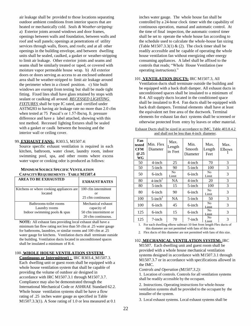
22
air leakage shall be provided to those locations separating
outdoor ambient conditions from interior spaces that are
heated or mechanically cold. Seals & Weather-stripping:
a) Exterior joints around windows and door frames,
openings between walls and foundation, between walls and
roof and wall panels; openings at penetrations of utility
services through walls, floors, and roofs; and at all other
openings in the building envelope, and between dwelling
units shall be sealed, caulked, a gasket or weather-stripping
to limit air leakage. Other exterior joints and seams and
seams shall be similarly treated or taped, or covered with
moisture vapor permeable house wrap. b) All exterior
doors or doors serving as access to an enclosed unheated
area shall be weather-stripped to limit air leakage around
the perimeter when in a closed position. c) Site built
windows are exempt from testing but shall be made tight
fitting. Fixed lites shall have glass retained by stops with
sealant or caulking all around. RECESSED LIGHTING
FIXTURES shall be type IC rated, and certified under
ASTM283 to having air leakage rate no more than 2.0 cfm
when tested at 75 Pascal’s or 1.57-lbs/sq. ft. pressure
difference and have a label attached, showing with this
test method. Recessed lighting fixtures shall be sealed
with a gasket or caulk between the housing and the
interior wall or ceiling cover.
99. EXHAUST FANS:, R303.5, M1507.4:
Source specific exhaust ventilation is required in each
kitchen, bathroom, water closet, laundry room, indoor
swimming pool, spa, and other rooms where excess
water vapor or cooking odor is produced as follows:
MINIMUM SOURCE SPECIFIC VENTILATION
CAPACITY REQUIREMENTS - TABLE M1507.4
AREA TO BE EXHAUSTED EXHAUST RATES
Kitchens or where cooking appliances are
located
100 cfm intermittent
or
25 cfm continuous
Bathrooms-toilet rooms
Laundry rooms
Indoor swimming pools & spas
Mechanical exhaust
capacity of
50 cfm intermittent or
20 cfm continuous.
NOTE: All exhaust fans providing local exhaust shall have a
minimum fan flow rating not less than 50 cfm at .25 water gauge
for bathrooms, laundries, or similar rooms and 100 cfm at .25
water gauge for kitchens. Ventilation ducts shall terminate outside
the building. Ventilation ducts located in unconditioned spaces
shall be insulated a minimum of R-4.
100. WHOLE HOUSE VENTILATION SYSTEM
Continuous or Intermittent) : IRC R303.4, M1507.3.
Each dwelling unit or guest room shall be equipped with a
whole house ventilation system that shall be capable of
providing the volume of outdoor air designed in
accordance with IRC M1507.3.1 through M1507.3.7.
Compliance may also be demonstrated through the
International Mechanical Code or ASHRAE Standard 62.2.
Whole house ventilation systems shall be have a flow
rating of .25 inches water gauge as specified in Table
M1507.3.3(1). A Sone rating of 1.0 or less measured at 0.1
inches water gauge. The whole house fan shall be
controlled by a 24-hour clock timer with the capability of
continuous operation, manual and automatic control. At
the time of final inspection, the automatic control timer
shall be set to operate the whole house fan according to
the schedule used to calculate the whole-house fan sizing
(Table M1507.3.3(1) & (2). The clock timer shall be
readily accessible and be capable of operating the whole
house ventilation fan without energizing other energy
consuming appliances. A label shall be affixed to the
controls that reads; “Whole House Ventilation (see
operating instructions).”
101. VENTILATION DUCTS: IRC M1507.3, All
Ventilation ducts shall terminate outside the building and
be equipped with a back draft damper. All exhaust ducts in
unconditioned spaces shall be insulated to a minimum of
R-4. All supply ducts located in the conditioned space
shall be insulated to R-4. Fan ducts shall be equipped with
back draft dampers. Terminal elements shall have at least
the equivalent net free area of the ductwork. Terminal
elements for exhaust fan duct systems shall be screened or
otherwise protected from entry by leaves or other material.
Exhaust Ducts shall be sized in accordance to IMC, Table 403.8.4.2
and shall not be less than 4-inch diameter.
1. For each dwelling elbow subtract 10 feet from length Flex ducts of
this diameter are not permitted with fans of this size.
2. Flex ducts of this diameter are not permitted with fans of this size.
102. MECHANICAL VENTILATION SYSTEM: IRC
M1507. Each dwelling unit and guest room shall be
provided with a whole house mechanical ventilation
systems designed in accordance with M1507.3.1 through
M1507.3.7 or in accordance with specifications allowed in
the IMC.
Controls and Operation (M1507.3.2):
1. Location of controls. Controls for all ventilation systems
shall be readily accessible by the occupant.
2. Instructions. Operating instructions for whole-house
ventilation systems shall be provided to the occupant by the
installer of the system.
3. Local exhaust systems. Local exhaust systems shall be
Fan
tested
CFM
@.25
WG
Min. Flex
Diameter
Max.
Length
in Feet
Min.
Smooth
Diameter
Max.
Length
Feet
Max.
Elbows 1
50 4-inch 25 4-inch 70 3
50 5-inch 90 5-inch 100 3
50 6-inch No
Limit 6-inch
No
Limit 3
80 4-inch2
NA 4-inch 20 3
80 5-inch 15 5-inch 100 3
80 6-inch 90 6-inch No
Limit 3
100 5-inch2 NA 5-inch 50 3
100 6-inch 45 6-inch No
Limit 3
125 6-inch 15 6-inch No
Limit 3
125 7-inch 70 7-inch No
Limit 3

23
controlled by manual switches, dehumidistats, timers, or other
approved means.
4. Continuous whole-house ventilation systems. Continuous
whole-house ventilation systems shall operate continuously and shall
be equipped with fan override control. Controls shall be capable of
operating the ventilation system without energizing other energy-
consuming appliances. A label shall be affixed to the controls that
reads; "Whole House Ventilation (see operating instructions)."
5. Intermittent whole-house ventilation systems. Intermittent
whole-house ventilation systems shall comply with the
following:
5.1. They shall be capable of operating intermittently and
continuously.
5.2. They shall have controls capable of operating the
exhaust fans, forced-air system fans, or supply fans without
energizing other energy-consuming appliances.
5.3. The ventilation rate shall be adjusted according to the
exception in Section 403.8.5.1.
5.4. The system shall be designed so that it can operate
automatically based on the type of control timer installed.
5.5. The intermittent mechanical ventilation system shall
operate at least one hour out of every four.
5.6. The system shall have a manual control and automatic
control, such as a 24-hour clock timer.
5.7. At the time of final inspection, the automatic control
shall be set to operate the whole-house fan according to the
schedule used to calculate the whole- house fan sizing.
5.8. A label shall be affixed to the control that reads
"Whole House Ventilation (see operating instructions)."
Operating Instructions and a whole-house ventilation
operation description shall be provided by installers. The
whole-house ventilation system shall provide outdoor air to
each habitable space at a continuous rate not less than that
specified in Table M1507.3.3(1). The system may operate
intermittently when the system has controls that that enable
operation for not less than 25% of each 4-hour segment and
the ventilation rate prescribed in Table M1507.3.3(1) is
multiplied by the factor determined in accordance with Table
M1507.3.3(2).
Outdoor air shall be distributed to each habitable room by
means such as individual inlets, separate duct systems, or
integrated with a forced air system. Where outdoor air
supplies are separated from exhaust points by doors,
provisions shall be made to ensure air flow by installation of
distribution ducts, undercutting doors, installation of grilles,
transoms or other similar means. Doors shall be undercut to a
minimum ½” above of the surface of the finish floor.
DWELLING UNIT FLOOR
AREA (square feet)
Number of Bedrooms
0-1 2-3 4-5
Airflow in CFM
< 1,500 30 45 60
1,501- 3,000 45 60 75
3,001 - 4,500 60 75 90
4,501 - 6,000 75 90 105
6,001 – 7,500 90 105 120
> 7,500 105 120 135
See Table M1507.3.3(1) for additional bedrooms
Intermittent mechanical fan shall operate not less than one hour every 4-
hours. Where the system has controls that enable operation for not less
than 25% every four hours the ventilation rate shall be multiplied by the
factor in Table M1507.3.3(2)
103. WHOLE-HOUSE VENTILATION SYSTEM
USING EXHAUST FANS: IRC M1507.3.4. Exhaust
fans providing whole-house ventilation shall have a
flow rating at 0.25 water gauge as specified in
accordance with Table 1507.3.3(1). The whole-house
fan shall sone rating of 1.0 or less measured at 0.1” w.g.
Individual outdoor air inlets shall be provided in each
habitable room where outdoor air supplies are separated
from exhaust points by doors, provisions shall be made
to ensure air flow by installation of distribution ducts,
undercutting doors, installation of grilles, transoms or
similar means. Doors shall be undercut to a minimum
of ½ inch above the surface of the finish floor.
Individual room outdoor air inlets shall: a) controllable
and secure opening. b) Sleeved or otherwise designed so
as not to compromise the thermal properties of the wall
or window in which they are placed. c) Any inlet or
combination of inlets which provide 10 cfm at 10
pascals are deemed equivalent to 4 square inches net
free area. Doors and operable lights in windows are not
deemed to meet the outdoor air supply intake
requirements. Outdoor air inlets shall be screened or
otherwise protected from entry by leaves or other
material. Outdoor air inlets shall be located so as not to
take air from the following areas: a) closer than 10’
from an appliance vent outlet, unless such vent outlet is
3’ above the outdoor air inlet. b) Where it will pick-up
objectionable odors, fumes or other flammable vapors.
c) A hazardous or unsanitary location. d) A room or
space having and fuel-burning appliances therein. e)
closer than 10’ from any vent opening of a plumbing
drainage system unless the vent is located at least 3’
above the air inlet. f) Attic, crawl spaces, or garages. g)
Asphalt roofs unless it is shown that no other location is
permissible. In such case the inlet opening shall be
located a min. of 2 feet from the nearest surface of the
asphalt roofing, measured from the intake opening.
104. INTERMITTENT WHOLE HOUSE
VENTILATION INTEGRATED WITH A
FORCED-AIR SYSTEM. (Make-up air through the
furnace): IRC M1507.3.5. Integrated ventilation
systems shall provide outdoor air at the rate calculated
using Table M1507.3.3. The ventilation system shall
distribute outdoor air to each habitable room through
the forced-air system ducts. The outside air inlet duct
shall terminate outside of the building and be connected
to the return air plenum of the forced air system at a
point within 4-ft upstream of the air handler. The
outdoor inlet shall be connected upstream of the forced
Table M1507.3.3(2)
Continuous Whole-house ventilation rate factors Run-time
% in each
4-hr period
25% 33% 50% 66% 75% 100%
Factor 4 3 2 1.5 1.3 1.0

24
air system blower and shall not be connected directly
into the furnace cabinet. The system shall be provided
with a motorized damper connected to the automatic
ventilation control as specified in M1507.3.2. The
required flow rate shall be verified by field-testing with
a flow hood or a flow measuring station. A copy of the
testing report shall be provided to the inspector during
inspection. The system shall be controlled by a 24-hour
clock timer with the capability of continuous operation,
manual and automatic. This control will control the
forced air system blower and the automatic damper.
The 24-hour timer shall be readily accessible and
capable of operating the whole house ventilation
system without energizing other energy-consuming
appliances. At the time of inspection the automatic
control timer shall be set to operate at least 8-hours a
day. A label shall be affixed to the control that reads,
“Whole House Ventilation (see operating instructions)”.
105. Intermittent Whole House Ventilation Using a
Supply Fan, IRC M1507.3.6. Supply fan ventilation
systems shall distribute outdoor air to each habitable
room through the forced-air system ducts or through
dedicated ducts to each habitable room. Supply fans
shall have the capacity to provide outdoor air specified
in Table M1507.3.3(1) at .40” w.g. per HVI 916. The
outdoor air must be filtered before it is delivered to
habitable rooms. Ducts shall be installed in accordance
to M1507.3.6.2, dampers in accordance to M1507.3.6.3.
106. Whole House Ventilation using Heat Recovery
Ventilation: M1507.3.7. Heat Recovery ventilation
systems shall be sized and installed in accordance to
manufacturer’s instructions and in accordance to
M1507.3.3(1). Minimum flow rating shall not be less
than that specified in Table M1507.3.3(1).
107. LIGHTING: IECC/WSEC R404 & Chapter 2. A
minimum of 75% of permanently installed lamps in
lighting fixtures shall be high-efficacy lamps. Fuel
gas lighting systems shall not have continuously
burning pilot lights. High efficiency lamps are defined
in Chapter 2. Compact fluorescent lamps, T-8 or
smaller diameter lenear fluorescent lamps or lamps with
an efficacy 1) 60 lumens per watt for lamps over 40
watts; 2) 50 lumens per watt for lamps over 15 watts to
40 watts; 3) 40 lumens per watt for lamps 15 watts or
less.
108. FIRE ACCESS: Mason County Title 14, Chapter
14.17 Standards for Fire Apparatus Access Roads.
All roads, driveways, or other means of access
serving structures, facilities, buildings or portions of
buildings hereafter constructed, altered, moved into,
or within, the jurisdiction and developed under permit
from Mason County shall meet the requirements of
the fire apparatus access road standards. (detail pages
contained within this checklist)

25