pl7 micro/junior/pro communication applications volume 2 · pl7 micro/junior/pro communication...
TRANSCRIPT

PL7 Micro/Junior/ProCommunication applicationsVolume 2 eng
3500
9572
_00
March 2005

2

Document Set
Document Set
At a Glance This manual has 3 volumes: � Volume 1
� Common communication function� Remoting of Nano PLCs� Communication by character mode� Communication by Uni-telway bus
� Volume 2� Communication by Modbus� Communication by modem� Communication by Modbus plus� Communication by FIPIO bus
� Volume 3� Communication by FIPWAY network� Communication by ETHERNET network� Multi-network architecture
3

Document Set
4
Table of Contents
About the Book . . . . . . . . . . . . . . . . . . . . . . . . . . . . . . . . . . . . . .13
Part I Communication via Modbus . . . . . . . . . . . . . . . . . . . . . . 15Introduction . . . . . . . . . . . . . . . . . . . . . . . . . . . . . . . . . . . . . . . . . . . . . . . . . . . . . 15
Chapter 1 General . . . . . . . . . . . . . . . . . . . . . . . . . . . . . . . . . . . . . . . . . . . . 17Introduction . . . . . . . . . . . . . . . . . . . . . . . . . . . . . . . . . . . . . . . . . . . . . . . . . . . . . 17About Modbus . . . . . . . . . . . . . . . . . . . . . . . . . . . . . . . . . . . . . . . . . . . . . . . . . . . 18Compatibilities . . . . . . . . . . . . . . . . . . . . . . . . . . . . . . . . . . . . . . . . . . . . . . . . . . . 19Compatibility between a TSX 37/57 PLC and a series 1000 PLC. . . . . . . . . . . . 20Performance . . . . . . . . . . . . . . . . . . . . . . . . . . . . . . . . . . . . . . . . . . . . . . . . . . . . 22Operating Mode. . . . . . . . . . . . . . . . . . . . . . . . . . . . . . . . . . . . . . . . . . . . . . . . . . 23
Chapter 2 Configuring Modbus communication . . . . . . . . . . . . . . . . . . . . 25Introduction . . . . . . . . . . . . . . . . . . . . . . . . . . . . . . . . . . . . . . . . . . . . . . . . . . . . . 25How to access the Modbus PCMCIA card parameters . . . . . . . . . . . . . . . . . . . . 26How to access the terminal port parameters . . . . . . . . . . . . . . . . . . . . . . . . . . . 27How to Access Parameters for TSX SCY 11601/21600/21601 Modules . . . . . . 28Modbus Configuration Screen. . . . . . . . . . . . . . . . . . . . . . . . . . . . . . . . . . . . . . . 29Accessible Modbus Functions. . . . . . . . . . . . . . . . . . . . . . . . . . . . . . . . . . . . . . . 30Application linked Modbus Parameters . . . . . . . . . . . . . . . . . . . . . . . . . . . . . . . . 31Modbus Parameters relating to transmission . . . . . . . . . . . . . . . . . . . . . . . . . . . 33
Chapter 3 Programming Modbus communication . . . . . . . . . . . . . . . . . . 37Introduction . . . . . . . . . . . . . . . . . . . . . . . . . . . . . . . . . . . . . . . . . . . . . . . . . . . . . 37Modbus Master Communication Function. . . . . . . . . . . . . . . . . . . . . . . . . . . . . . 38Modbus Slave Communication Function. . . . . . . . . . . . . . . . . . . . . . . . . . . . . . . 40Using the SEND_REQ communication function . . . . . . . . . . . . . . . . . . . . . . . . . 42Example 1: SEND_REQ function with Echo request . . . . . . . . . . . . . . . . . . . . . 43Example 2: SEND_REQ function with Word read request. . . . . . . . . . . . . . . . . 44Example 3: SEND_REQ Function with Bit Read Request . . . . . . . . . . . . . . . . . 46Example 4: READ_VAR function for reading bits . . . . . . . . . . . . . . . . . . . . . . . . 48
5

Chapter 4 Debugging Modbus communication . . . . . . . . . . . . . . . . . . . . 49Introduction . . . . . . . . . . . . . . . . . . . . . . . . . . . . . . . . . . . . . . . . . . . . . . . . . . . . . 49Modbus debug screen . . . . . . . . . . . . . . . . . . . . . . . . . . . . . . . . . . . . . . . . . . . . . 50Modbus Master debugging screen. . . . . . . . . . . . . . . . . . . . . . . . . . . . . . . . . . . . 51Debug screen in Modbus slave type . . . . . . . . . . . . . . . . . . . . . . . . . . . . . . . . . . 52How to test a communication channel . . . . . . . . . . . . . . . . . . . . . . . . . . . . . . . . . 53
Chapter 5 Language objects associated with Modbus communication 55Introduction . . . . . . . . . . . . . . . . . . . . . . . . . . . . . . . . . . . . . . . . . . . . . . . . . . . . . 55Implicit exchange language object for a Modbus function . . . . . . . . . . . . . . . . . . 56Explicit exchange language objects for a Modbus function . . . . . . . . . . . . . . . . . 58Explicit exchange management and report . . . . . . . . . . . . . . . . . . . . . . . . . . . . . 61Language objects associated with the configuration . . . . . . . . . . . . . . . . . . . . . . 62System objects of the Modbus function on Terminal port . . . . . . . . . . . . . . . . . . 64
Part II Communication via Modem . . . . . . . . . . . . . . . . . . . . . . .65Introduction . . . . . . . . . . . . . . . . . . . . . . . . . . . . . . . . . . . . . . . . . . . . . . . . . . . . . 65
Chapter 6 Communication via Modem . . . . . . . . . . . . . . . . . . . . . . . . . . . 67Introduction . . . . . . . . . . . . . . . . . . . . . . . . . . . . . . . . . . . . . . . . . . . . . . . . . . . . . 67
6.1 Introduction to communication via Modem . . . . . . . . . . . . . . . . . . . . . . . . . . . . . 68Introduction . . . . . . . . . . . . . . . . . . . . . . . . . . . . . . . . . . . . . . . . . . . . . . . . . . . . . 68Modems . . . . . . . . . . . . . . . . . . . . . . . . . . . . . . . . . . . . . . . . . . . . . . . . . . . . . . . . 69Standard configuration for communication via modem . . . . . . . . . . . . . . . . . . . . 70Other configurations for communication via modem . . . . . . . . . . . . . . . . . . . . . . 71Principles of communication between two stations . . . . . . . . . . . . . . . . . . . . . . . 73
6.2 Characteristics . . . . . . . . . . . . . . . . . . . . . . . . . . . . . . . . . . . . . . . . . . . . . . . . . . . 74Introduction . . . . . . . . . . . . . . . . . . . . . . . . . . . . . . . . . . . . . . . . . . . . . . . . . . . . . 74Hardware Compatibility . . . . . . . . . . . . . . . . . . . . . . . . . . . . . . . . . . . . . . . . . . . . 75Software compatibility . . . . . . . . . . . . . . . . . . . . . . . . . . . . . . . . . . . . . . . . . . . . . 76
6.3 Setting up communication via Modem. . . . . . . . . . . . . . . . . . . . . . . . . . . . . . . . . 78Introduction . . . . . . . . . . . . . . . . . . . . . . . . . . . . . . . . . . . . . . . . . . . . . . . . . . . . . 78Set up methodology. . . . . . . . . . . . . . . . . . . . . . . . . . . . . . . . . . . . . . . . . . . . . . . 79Setting up UNI-TELWAY communication between PLCs via the TSX MDM 10 card . . . . . . . . . . . . . . . . . . . . . . . . . . . . . . . . . . . . . . . . . . . . . . . . 80Communication between PLCs using an external modem . . . . . . . . . . . . . . . . . 81Setting up communication from PL7 . . . . . . . . . . . . . . . . . . . . . . . . . . . . . . . . . . 82How to configure the Uni-telway driver with a modem. . . . . . . . . . . . . . . . . . . . . 84How to Configure Modem Connection. . . . . . . . . . . . . . . . . . . . . . . . . . . . . . . . . 85How to modify modem configuration parameters . . . . . . . . . . . . . . . . . . . . . . . . 86
6
Chapter 7 Configuring Modem communication . . . . . . . . . . . . . . . . . . . .87Introduction . . . . . . . . . . . . . . . . . . . . . . . . . . . . . . . . . . . . . . . . . . . . . . . . . . . . . 87How to access PCMCIA modem card parameters . . . . . . . . . . . . . . . . . . . . . . . 88Modem configuration screen. . . . . . . . . . . . . . . . . . . . . . . . . . . . . . . . . . . . . . . . 89Parameters in Uni-telway mode . . . . . . . . . . . . . . . . . . . . . . . . . . . . . . . . . . . . . 90Parameters in character mode . . . . . . . . . . . . . . . . . . . . . . . . . . . . . . . . . . . . . . 92Modem parameters . . . . . . . . . . . . . . . . . . . . . . . . . . . . . . . . . . . . . . . . . . . . . . . 94Modem parameters for a called station. . . . . . . . . . . . . . . . . . . . . . . . . . . . . . . . 95Modem parameters for a calling station . . . . . . . . . . . . . . . . . . . . . . . . . . . . . . . 96
Chapter 8 Programming Modem communication . . . . . . . . . . . . . . . . . . . 99Introduction . . . . . . . . . . . . . . . . . . . . . . . . . . . . . . . . . . . . . . . . . . . . . . . . . . . . . 99CALL_MODEM communication function. . . . . . . . . . . . . . . . . . . . . . . . . . . . . . 100Modem specific management parameters . . . . . . . . . . . . . . . . . . . . . . . . . . . . 102Coding of exchanges. . . . . . . . . . . . . . . . . . . . . . . . . . . . . . . . . . . . . . . . . . . . . 105Guide to choosing connection parameters in Uni-telway mode . . . . . . . . . . . . 107Guide to choosing connection parameters in character mode . . . . . . . . . . . . . 110Examples of connection, disconnection, and reset with a remote station . . . . . 112Examples of communication between two PLCs . . . . . . . . . . . . . . . . . . . . . . . 114
Chapter 9 Debugging Modem communication . . . . . . . . . . . . . . . . . . . .117Introduction . . . . . . . . . . . . . . . . . . . . . . . . . . . . . . . . . . . . . . . . . . . . . . . . . . . . 117Modem debugging screen. . . . . . . . . . . . . . . . . . . . . . . . . . . . . . . . . . . . . . . . . 118Debugging parameters . . . . . . . . . . . . . . . . . . . . . . . . . . . . . . . . . . . . . . . . . . . 119
Chapter 10 Language objects associated with Modem communication 121Introduction . . . . . . . . . . . . . . . . . . . . . . . . . . . . . . . . . . . . . . . . . . . . . . . . . . . . 121Language objects in implicit exchange . . . . . . . . . . . . . . . . . . . . . . . . . . . . . . . 122Language objects for explicit exchange . . . . . . . . . . . . . . . . . . . . . . . . . . . . . . 123Explicit exchange management and reports . . . . . . . . . . . . . . . . . . . . . . . . . . . 127Language objects associated with configuration. . . . . . . . . . . . . . . . . . . . . . . . 128
Chapter 11 Appendices . . . . . . . . . . . . . . . . . . . . . . . . . . . . . . . . . . . . . . . . 131Introduction . . . . . . . . . . . . . . . . . . . . . . . . . . . . . . . . . . . . . . . . . . . . . . . . . . . . 131AT commands . . . . . . . . . . . . . . . . . . . . . . . . . . . . . . . . . . . . . . . . . . . . . . . . . . 133A/ - Command re-execution . . . . . . . . . . . . . . . . . . . . . . . . . . . . . . . . . . . . . . . 135AT = x - Write to the selected S register . . . . . . . . . . . . . . . . . . . . . . . . . . . . . . 136AT? - Read the selected S register . . . . . . . . . . . . . . . . . . . . . . . . . . . . . . . . . . 137A - Answer. . . . . . . . . . . . . . . . . . . . . . . . . . . . . . . . . . . . . . . . . . . . . . . . . . . . . 138Cn - Checking for carrier . . . . . . . . . . . . . . . . . . . . . . . . . . . . . . . . . . . . . . . . . . 139Dn - Dialing . . . . . . . . . . . . . . . . . . . . . . . . . . . . . . . . . . . . . . . . . . . . . . . . . . . . 140En - Local command echo. . . . . . . . . . . . . . . . . . . . . . . . . . . . . . . . . . . . . . . . . 142Hn - Disconnection (hang up) . . . . . . . . . . . . . . . . . . . . . . . . . . . . . . . . . . . . . . 143In - Identification . . . . . . . . . . . . . . . . . . . . . . . . . . . . . . . . . . . . . . . . . . . . . . . . 144Ln - Loudspeaker volume . . . . . . . . . . . . . . . . . . . . . . . . . . . . . . . . . . . . . . . . . 145Mn - Loudspeaker command. . . . . . . . . . . . . . . . . . . . . . . . . . . . . . . . . . . . . . . 146
7
Nn - Activation of automatic mode. . . . . . . . . . . . . . . . . . . . . . . . . . . . . . . . . . . 147On- Return to on-line data mode . . . . . . . . . . . . . . . . . . . . . . . . . . . . . . . . . . . . 148P - Default adjustment of pulse dialing . . . . . . . . . . . . . . . . . . . . . . . . . . . . . . . 149Qn - Activation / deactivation of result codes. . . . . . . . . . . . . . . . . . . . . . . . . . . 150Sn - S register read / write . . . . . . . . . . . . . . . . . . . . . . . . . . . . . . . . . . . . . . . . . 151T - Default adjustment of tone dialing . . . . . . . . . . . . . . . . . . . . . . . . . . . . . . . . 152Vn - Form of the result codes. . . . . . . . . . . . . . . . . . . . . . . . . . . . . . . . . . . . . . . 153Wn - Error correction messages control . . . . . . . . . . . . . . . . . . . . . . . . . . . . . . 154Xn - Extended result codes . . . . . . . . . . . . . . . . . . . . . . . . . . . . . . . . . . . . . . . . 155Yn - Disconnection after prolonged inactivity. . . . . . . . . . . . . . . . . . . . . . . . . . . 159Zn - Software reset of modem and restoration of profile . . . . . . . . . . . . . . . . . . 160&Cn - RLSD Option (detection of DCD carrier) . . . . . . . . . . . . . . . . . . . . . . . . . 161&Dn - DTR Option (Data Terminal Ready) . . . . . . . . . . . . . . . . . . . . . . . . . . . . 162&Fn - Restoration of the factory configuration (profile) . . . . . . . . . . . . . . . . . . . 163&Gn - Selection of guard tone . . . . . . . . . . . . . . . . . . . . . . . . . . . . . . . . . . . . . . 164&Kn – Flow control. . . . . . . . . . . . . . . . . . . . . . . . . . . . . . . . . . . . . . . . . . . . . . . 165&Pn - Selection of pulse dialing close/open report . . . . . . . . . . . . . . . . . . . . . . 166&Qn - Synchronous/asynchronous mode . . . . . . . . . . . . . . . . . . . . . . . . . . . . . 167&Rn - RTS/CTS option. . . . . . . . . . . . . . . . . . . . . . . . . . . . . . . . . . . . . . . . . . . . 168&Sn - DSR Monitoring (Data Station Ready) . . . . . . . . . . . . . . . . . . . . . . . . . . . 169&V - Display of current configuration and stored profiles. . . . . . . . . . . . . . . . . . 170&Wn – Storage of the current configuration. . . . . . . . . . . . . . . . . . . . . . . . . . . . 171&Yn - Designation of a default profile on reset . . . . . . . . . . . . . . . . . . . . . . . . . 172&Zn – Storage of telephone numbers . . . . . . . . . . . . . . . . . . . . . . . . . . . . . . . . 173%Cn - Activation / deactivation of data compression. . . . . . . . . . . . . . . . . . . . . 174%En - Activation/deactivation of line quality monitoring or automatic resynchronization or fallback/increase of transfer rate . . . . . . . . . . . . . . . . . . . 175%L - Level of line signal . . . . . . . . . . . . . . . . . . . . . . . . . . . . . . . . . . . . . . . . . . . 176%Q - Quality of line signal . . . . . . . . . . . . . . . . . . . . . . . . . . . . . . . . . . . . . . . . . 177\Kn - BREAK control . . . . . . . . . . . . . . . . . . . . . . . . . . . . . . . . . . . . . . . . . . . . . 178\Nn - Operating mode . . . . . . . . . . . . . . . . . . . . . . . . . . . . . . . . . . . . . . . . . . . . 180Values of the registers of the TSX MDM 10 card in a PLC . . . . . . . . . . . . . . . . 181
Part III Communication via Modbus Plus . . . . . . . . . . . . . . . . . 183Introduction . . . . . . . . . . . . . . . . . . . . . . . . . . . . . . . . . . . . . . . . . . . . . . . . . . . . 183
Chapter 12 General . . . . . . . . . . . . . . . . . . . . . . . . . . . . . . . . . . . . . . . . . . . 185Introduction . . . . . . . . . . . . . . . . . . . . . . . . . . . . . . . . . . . . . . . . . . . . . . . . . . . . 185Introduction . . . . . . . . . . . . . . . . . . . . . . . . . . . . . . . . . . . . . . . . . . . . . . . . . . . . 186Compatibility . . . . . . . . . . . . . . . . . . . . . . . . . . . . . . . . . . . . . . . . . . . . . . . . . . . 187Integration into an X-WAY architecture . . . . . . . . . . . . . . . . . . . . . . . . . . . . . . . 188Integration into a Modbus Plus architecture. . . . . . . . . . . . . . . . . . . . . . . . . . . . 191
Chapter 13 Peer Cop service . . . . . . . . . . . . . . . . . . . . . . . . . . . . . . . . . . . 193Peer Cop service . . . . . . . . . . . . . . . . . . . . . . . . . . . . . . . . . . . . . . . . . . . . . . . . 193
8
Chapter 14 Configuring Modbus Plus communication . . . . . . . . . . . . . . 197Introduction . . . . . . . . . . . . . . . . . . . . . . . . . . . . . . . . . . . . . . . . . . . . . . . . . . . . 197How to access the Modbus Plus PCMCIA card parameters . . . . . . . . . . . . . . . 198Modbus Plus configuration screen . . . . . . . . . . . . . . . . . . . . . . . . . . . . . . . . . . 199Functions accessible from Modbus Plus. . . . . . . . . . . . . . . . . . . . . . . . . . . . . . 200Modbus Plus configuration parameters. . . . . . . . . . . . . . . . . . . . . . . . . . . . . . . 201Configuring the specific inputs and outputs. . . . . . . . . . . . . . . . . . . . . . . . . . . . 202
Chapter 15 Programming Modbus Plus communication . . . . . . . . . . . . .205Introduction . . . . . . . . . . . . . . . . . . . . . . . . . . . . . . . . . . . . . . . . . . . . . . . . . . . . 205Read and write service on local segment . . . . . . . . . . . . . . . . . . . . . . . . . . . . . 206Exchange service on remote Modbus Plus networks . . . . . . . . . . . . . . . . . . . . 208Examples of Exchanges on Remote Networks . . . . . . . . . . . . . . . . . . . . . . . . . 210Diagnostic service . . . . . . . . . . . . . . . . . . . . . . . . . . . . . . . . . . . . . . . . . . . . . . . 213Global data exchange service. . . . . . . . . . . . . . . . . . . . . . . . . . . . . . . . . . . . . . 215
Chapter 16 Debugging Modbus Plus communication . . . . . . . . . . . . . . . 217Introduction . . . . . . . . . . . . . . . . . . . . . . . . . . . . . . . . . . . . . . . . . . . . . . . . . . . . 217Modbus Plus debugging screen . . . . . . . . . . . . . . . . . . . . . . . . . . . . . . . . . . . . 218Modbus Plus debugging screen . . . . . . . . . . . . . . . . . . . . . . . . . . . . . . . . . . . . 219
Chapter 17 Language objects associated with Modbus Plus communication . . . . . . . . . . . . . . . . . . . . . . . . . . . . . . . . . . . . .221Introduction . . . . . . . . . . . . . . . . . . . . . . . . . . . . . . . . . . . . . . . . . . . . . . . . . . . . 221Implicit Exchange Language Object . . . . . . . . . . . . . . . . . . . . . . . . . . . . . . . . . 222Explicit exchange language object . . . . . . . . . . . . . . . . . . . . . . . . . . . . . . . . . . 225Explicit exchange management and report . . . . . . . . . . . . . . . . . . . . . . . . . . . . 227Language objects associated with configuration. . . . . . . . . . . . . . . . . . . . . . . . 228
Part IV Communication via FIPIO bus . . . . . . . . . . . . . . . . . . . 231Introduction . . . . . . . . . . . . . . . . . . . . . . . . . . . . . . . . . . . . . . . . . . . . . . . . . . . . 231
Chapter 18 Communication via FIPIO bus. . . . . . . . . . . . . . . . . . . . . . . . .233Introduction . . . . . . . . . . . . . . . . . . . . . . . . . . . . . . . . . . . . . . . . . . . . . . . . . . . . 233
18.1 Introduction to Fipio communication . . . . . . . . . . . . . . . . . . . . . . . . . . . . . . . . . 234Introduction . . . . . . . . . . . . . . . . . . . . . . . . . . . . . . . . . . . . . . . . . . . . . . . . . . . . 234Introduction . . . . . . . . . . . . . . . . . . . . . . . . . . . . . . . . . . . . . . . . . . . . . . . . . . . . 235Addressing of language objects for modules remoted on the FIPIO bus . . . . . 236
18.2 Characteristics. . . . . . . . . . . . . . . . . . . . . . . . . . . . . . . . . . . . . . . . . . . . . . . . . . 239Introduction . . . . . . . . . . . . . . . . . . . . . . . . . . . . . . . . . . . . . . . . . . . . . . . . . . . . 239Hardware compatibility relating to the bus manager . . . . . . . . . . . . . . . . . . . . . 240Software compatibility relating to the bus manager. . . . . . . . . . . . . . . . . . . . . . 241Software compatibility: Network transparency . . . . . . . . . . . . . . . . . . . . . . . . . 242Software compatibility: communication with the exterior. . . . . . . . . . . . . . . . . . 244Compatibility information relating to TBX devices. . . . . . . . . . . . . . . . . . . . . . . 245Compatibility information relating to Momentum devices . . . . . . . . . . . . . . . . . 246
9

Compatibility information relating to the programming terminal. . . . . . . . . . . . . 247Compatibility information relating to other devices . . . . . . . . . . . . . . . . . . . . . . 248FIPIO bus operating mode. . . . . . . . . . . . . . . . . . . . . . . . . . . . . . . . . . . . . . . . . 250Network cycle time: mono task application . . . . . . . . . . . . . . . . . . . . . . . . . . . . 252Network cycle time: multitasking application . . . . . . . . . . . . . . . . . . . . . . . . . . . 254Example of calculating the network cycle times of a multitasking application . . 257
Chapter 19 Configuring Fipio communication . . . . . . . . . . . . . . . . . . . . . 259Introduction . . . . . . . . . . . . . . . . . . . . . . . . . . . . . . . . . . . . . . . . . . . . . . . . . . . . 259
19.1 General information on configuration. . . . . . . . . . . . . . . . . . . . . . . . . . . . . . . . . 260Configuration mode . . . . . . . . . . . . . . . . . . . . . . . . . . . . . . . . . . . . . . . . . . . . . . 260
19.2 Fipio bus configuration. . . . . . . . . . . . . . . . . . . . . . . . . . . . . . . . . . . . . . . . . . . . 261Introduction . . . . . . . . . . . . . . . . . . . . . . . . . . . . . . . . . . . . . . . . . . . . . . . . . . . . 261How to access the FIPIO configuration screen . . . . . . . . . . . . . . . . . . . . . . . . . 262FIPIO bus configuration screen . . . . . . . . . . . . . . . . . . . . . . . . . . . . . . . . . . . . . 263How to add a device on to the bus. . . . . . . . . . . . . . . . . . . . . . . . . . . . . . . . . . . 265How to modify/delete/move/duplicate a bus device. . . . . . . . . . . . . . . . . . . . . . 267How to access the FIPIO bus properties screen . . . . . . . . . . . . . . . . . . . . . . . . 269FIPIO bus properties configuration screen . . . . . . . . . . . . . . . . . . . . . . . . . . . . 270Properties of the FIPIO bus: General tab. . . . . . . . . . . . . . . . . . . . . . . . . . . . . . 271Properties of the Fipio bus: Expert tab. . . . . . . . . . . . . . . . . . . . . . . . . . . . . . . . 272Expert Tab: Manual Mode . . . . . . . . . . . . . . . . . . . . . . . . . . . . . . . . . . . . . . . . . 273
19.3 Configuration of devices on the Fipio bus . . . . . . . . . . . . . . . . . . . . . . . . . . . . . 275Introduction . . . . . . . . . . . . . . . . . . . . . . . . . . . . . . . . . . . . . . . . . . . . . . . . . . . . 275How to access the FIPIO configuration screen . . . . . . . . . . . . . . . . . . . . . . . . . 276Configuration screen of a FIPIO device. . . . . . . . . . . . . . . . . . . . . . . . . . . . . . . 277How to access the different parameters according to device type. . . . . . . . . . . 279
19.4 Input/output management by the PL7 tasks . . . . . . . . . . . . . . . . . . . . . . . . . . . 280Introduction . . . . . . . . . . . . . . . . . . . . . . . . . . . . . . . . . . . . . . . . . . . . . . . . . . . . 280How to access PL7 task configuration in FIPIO mode. . . . . . . . . . . . . . . . . . . . 281Configuration screen of a FIPIO processor . . . . . . . . . . . . . . . . . . . . . . . . . . . . 282FIPIO input/output management using PL7 tasks . . . . . . . . . . . . . . . . . . . . . . . 283
19.5 Confirmation of the Fipio bus configuration . . . . . . . . . . . . . . . . . . . . . . . . . . . . 284Introduction . . . . . . . . . . . . . . . . . . . . . . . . . . . . . . . . . . . . . . . . . . . . . . . . . . . . 284Confirming the configuration . . . . . . . . . . . . . . . . . . . . . . . . . . . . . . . . . . . . . . . 285Confirmation refused, examples . . . . . . . . . . . . . . . . . . . . . . . . . . . . . . . . . . . . 287
Chapter 20 Programming Fipio communication . . . . . . . . . . . . . . . . . . . 289Introduction . . . . . . . . . . . . . . . . . . . . . . . . . . . . . . . . . . . . . . . . . . . . . . . . . . . . 289FIPIO error processing . . . . . . . . . . . . . . . . . . . . . . . . . . . . . . . . . . . . . . . . . . . 290Examples of explicit exchange saturation detection . . . . . . . . . . . . . . . . . . . . . 292
10

Chapter 21 Debugging a Fipio communication. . . . . . . . . . . . . . . . . . . . . 295Introduction . . . . . . . . . . . . . . . . . . . . . . . . . . . . . . . . . . . . . . . . . . . . . . . . . . . . 295Debugging mode. . . . . . . . . . . . . . . . . . . . . . . . . . . . . . . . . . . . . . . . . . . . . . . . 296How to access the remote device debugging screens . . . . . . . . . . . . . . . . . . . 297FIPIO bus device debugging screen . . . . . . . . . . . . . . . . . . . . . . . . . . . . . . . . . 298
Chapter 22 Fipio communication diagnostics. . . . . . . . . . . . . . . . . . . . . . 301Introduction . . . . . . . . . . . . . . . . . . . . . . . . . . . . . . . . . . . . . . . . . . . . . . . . . . . . 301Diagnostics mode . . . . . . . . . . . . . . . . . . . . . . . . . . . . . . . . . . . . . . . . . . . . . . . 302How to access the FIPIO bus monitoring screen . . . . . . . . . . . . . . . . . . . . . . . 303Diagnostics screen: FIPIO bus monitoring . . . . . . . . . . . . . . . . . . . . . . . . . . . . 304How to access the device monitoring screen . . . . . . . . . . . . . . . . . . . . . . . . . . 306Diagnostics screens: device monitoring . . . . . . . . . . . . . . . . . . . . . . . . . . . . . . 307How to access the monitoring screen for one device . . . . . . . . . . . . . . . . . . . . 309Diagnostics screen: single device monitoring . . . . . . . . . . . . . . . . . . . . . . . . . . 310How to access the communication error history screen . . . . . . . . . . . . . . . . . . 312Diagnostics screen: communication error history . . . . . . . . . . . . . . . . . . . . . . . 313
Chapter 23 Language objects associated with Fipio communication . . 315Introduction . . . . . . . . . . . . . . . . . . . . . . . . . . . . . . . . . . . . . . . . . . . . . . . . . . . . 315Language objects in implicit exchange . . . . . . . . . . . . . . . . . . . . . . . . . . . . . . . 316Language object for explicit exchange . . . . . . . . . . . . . . . . . . . . . . . . . . . . . . . 317Explicit exchange management and reports . . . . . . . . . . . . . . . . . . . . . . . . . . . 319
Chapter 24 Fipio communication standard profiles . . . . . . . . . . . . . . . . . 321Introduction . . . . . . . . . . . . . . . . . . . . . . . . . . . . . . . . . . . . . . . . . . . . . . . . . . . . 321
24.1 Introduction to standard Fipio communication profiles . . . . . . . . . . . . . . . . . . . 322Introduction . . . . . . . . . . . . . . . . . . . . . . . . . . . . . . . . . . . . . . . . . . . . . . . . . . . . 322Standard profiles: general . . . . . . . . . . . . . . . . . . . . . . . . . . . . . . . . . . . . . . . . . 323Designation of a standard profile. . . . . . . . . . . . . . . . . . . . . . . . . . . . . . . . . . . . 324List of the standard profiles proposed in catalog by PL7. . . . . . . . . . . . . . . . . . 325
24.2 Configuration of the Fipio bus standard profiles . . . . . . . . . . . . . . . . . . . . . . . . 327Introduction . . . . . . . . . . . . . . . . . . . . . . . . . . . . . . . . . . . . . . . . . . . . . . . . . . . . 327Configuration screen of a standard profile . . . . . . . . . . . . . . . . . . . . . . . . . . . . 328How to modify the parameters of a standard profile . . . . . . . . . . . . . . . . . . . . . 330Adjustment mode . . . . . . . . . . . . . . . . . . . . . . . . . . . . . . . . . . . . . . . . . . . . . . . 332
24.3 Debugging the Fipio bus standard profiles . . . . . . . . . . . . . . . . . . . . . . . . . . . . 333Introduction . . . . . . . . . . . . . . . . . . . . . . . . . . . . . . . . . . . . . . . . . . . . . . . . . . . . 333Debugging screen of a standard profile . . . . . . . . . . . . . . . . . . . . . . . . . . . . . . 334How to modify the debugging parameters of a standard profile . . . . . . . . . . . . 336
24.4 Language objects associated with the Fipio bus standard profiles . . . . . . . . . . 338Introduction . . . . . . . . . . . . . . . . . . . . . . . . . . . . . . . . . . . . . . . . . . . . . . . . . . . . 338Summary of the objects which can be accessed via the standard profiles . . . . 339Language objects in implicit exchange . . . . . . . . . . . . . . . . . . . . . . . . . . . . . . . 341Language object for explicit exchange . . . . . . . . . . . . . . . . . . . . . . . . . . . . . . . 343Language objects associated with configuration. . . . . . . . . . . . . . . . . . . . . . . . 346
11

Chapter 25 Fipio Agent . . . . . . . . . . . . . . . . . . . . . . . . . . . . . . . . . . . . . . . . 347Introduction . . . . . . . . . . . . . . . . . . . . . . . . . . . . . . . . . . . . . . . . . . . . . . . . . . . . 347
25.1 Introduction to Fipio Agents . . . . . . . . . . . . . . . . . . . . . . . . . . . . . . . . . . . . . . . . 348Introduction . . . . . . . . . . . . . . . . . . . . . . . . . . . . . . . . . . . . . . . . . . . . . . . . . . . . 348FIPIO Agent: General . . . . . . . . . . . . . . . . . . . . . . . . . . . . . . . . . . . . . . . . . . . . 349Periodic data exchange . . . . . . . . . . . . . . . . . . . . . . . . . . . . . . . . . . . . . . . . . . . 350Special cases. . . . . . . . . . . . . . . . . . . . . . . . . . . . . . . . . . . . . . . . . . . . . . . . . . . 351Communication from an FIPIO Agent . . . . . . . . . . . . . . . . . . . . . . . . . . . . . . . . 353
25.2 Configuration of Fipio Agents. . . . . . . . . . . . . . . . . . . . . . . . . . . . . . . . . . . . . . . 355Introduction . . . . . . . . . . . . . . . . . . . . . . . . . . . . . . . . . . . . . . . . . . . . . . . . . . . . 355How to access the FIPIO Agent parameters via PCMCIA cards . . . . . . . . . . . . 356FIPIO Agent configuration screen . . . . . . . . . . . . . . . . . . . . . . . . . . . . . . . . . . . 357
25.3 Debugging Fipio Agents. . . . . . . . . . . . . . . . . . . . . . . . . . . . . . . . . . . . . . . . . . . 358FIPIO Agent debugging screen . . . . . . . . . . . . . . . . . . . . . . . . . . . . . . . . . . . . . 358
25.4 Language objects associated with the Fipio Agents . . . . . . . . . . . . . . . . . . . . . 359Introduction . . . . . . . . . . . . . . . . . . . . . . . . . . . . . . . . . . . . . . . . . . . . . . . . . . . . 359Language objects in implicit exchange . . . . . . . . . . . . . . . . . . . . . . . . . . . . . . . 360Language object for explicit exchange. . . . . . . . . . . . . . . . . . . . . . . . . . . . . . . . 361Explicit exchange management and reports . . . . . . . . . . . . . . . . . . . . . . . . . . . 362Language objects associated with configuration . . . . . . . . . . . . . . . . . . . . . . . . 363
Index . . . . . . . . . . . . . . . . . . . . . . . . . . . . . . . . . . . . . . . . . . . . . . 365
12

About the Book
At a Glance
Document Scope This manual deals with the software implementation of the communication application.
Validity Note The updated version of this publication takes into account the functionalities of PL7 V4.5.
User Comments We welcome your comments about this document. You can reach us by e-mail at [email protected]
13

About the Book
14

I
Communication via ModbusIntroduction
Subject of this part
This part introduces the principles of configuring and communicating with Modbus via PL7 software.
What’s in this Part?
This part contains the following chapters:
Chapter Chapter Name Page
1 General 17
2 Configuring Modbus communication 25
3 Programming Modbus communication 37
4 Debugging Modbus communication 49
5 Language objects associated with Modbus communication 55
15

Communication via Modbus
16

1
GeneralIntroduction
Aim of this Chapter
This Chapter introduces Modbus communication and its services.
What’s in this Chapter?
This chapter contains the following topics:
Topic Page
About Modbus 18
Compatibilities 19
Compatibility between a TSX 37/57 PLC and a series 1000 PLC 20
Performance 22
Operating Mode 23
17

Modbus communication: General
About Modbus
Introduction Communication by Modbus allows data to be exchanged between all devices connected to the bus. Modbus is a protocol which creates a hierarchical structure (one master and several slaves).
The master manages all exchanges according to two types of dialog:� the master exchanges data with the slave and awaits a response,� the master exchanges data with all slaves and does not await a response
(general broadcast).
Associated manuals
For further information, you may consult the following manuals:
Title Description
Modbus - User guide Detailed description of Modbus protocol
Micro PLCs - Installation manual Hardware implementationSee manual TSX DM 37_T3.
Premium PLCs - Installation manual Hardware implementationSee manual TSX DM 57_T4.
18

Modbus communication: General
Compatibilities
Hardware This communication type is available for� Premium PLCs through:
� a PCMCIA TSX SCP 111 card associated with the RS232 physical layer,� a PCMCIA TSX SCP 112 card associated with 20 mA current loops,� a PCMCIA TSX SCP 114 card associated with RS422 and RS485 physical
layers,� a Built-in Link with a TSX SCY 11601/21600 / 21601 module associated with
the RS485 physical layer.� Version V3.3 Micro is configured in slave mode through the terminal port
associated with the RS485 physical layer.� Version V5.0 micro is configured in master mode (TSX 37-10/21/22 only) or in
slave mode through the terminal port associated with the RS485 physical layer.� The micro supports the PCMCIA cards described above.
Software The maximum frame size is 256 bytes.
PCMCIA cards and the TSX SCY 11601/21600 / 21601 module’s built-in link can process 8 communication functions at once in Modbus master mode.
Modbus master mode is only available on the Terminal Port from version V4.2 of the PL7 software. It is not possible to download a Modbus master configured application to a Micro of version V5.0 or below.The PL7 program’s MAST task can, in Modbus master mode, process up to 4 communication functions at once via the Terminal Port. In addition, an error code is sent.
The READ_VAR communication function can read up to 1000 consecutive bits in any remote device. To read more than 1000 bits, the SEND_REQ communication function must be used.
������Nano, Micro and Premium PLCs cannot send more than 1000 bits after a read request.
19

Modbus communication: General
Compatibility between a TSX 37/57 PLC and a series 1000 PLC
At a Glance The READ_VAR and WRITE_VAR functions are used to read and write objects contained in series 1000 PLCs. These include words, double words, floating points and character strings.
Memory addressing
The address of the object in the series 1000 PLC memory determines the type of the object to be accessed.
This table shows the access addresses for a series 1000 APRIL5000 PLC with memory extension.
Programming rules
When you wish to access the objects of a series 1000 PLC, the index of the first object to read (or write) is the access address.Example:� Read %M0 bit
READ_VAR(ADR#0.1.3, ‘%M’, �������, 1, ...)� Read word %MD25000
READ_VAR(ADR#0.1.3, ‘%MW’, �������, 2, ...)
Moreover, these communication functions cannot be used to exchange double words or character strings via the Modbus protocol. If needed, it is possible to perform the transfer in %MW form, the application must determine the direction in which the words are stored.
The diagnostics functions can be accessed via the SEND_REQ function.
Type of variable APRIL5000 with extension
PLC address Access address (in hexadecimal)
%M internal bits %M0%M4095
A000AFFF
%MW data words %MW0%MW24999
061A7
%MD data words %MD25000%MD26998
61A86976
%FD data words %FD27000%FD28998
69787146
%CH data words %CH29000%CH43903
7148AB7F
20
Modbus communication: General
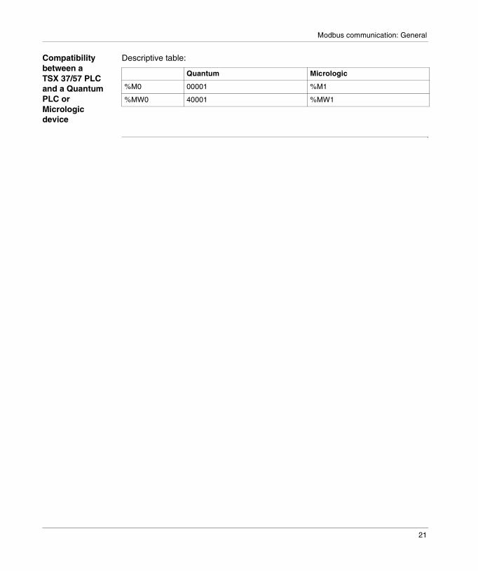
Compatibility between a TSX 37/57 PLC and a Quantum PLC or Micrologic device
Descriptive table:
Quantum Micrologic
%M0 00001 %M1
%MW0 40001 %MW1
21
Modbus communication: General
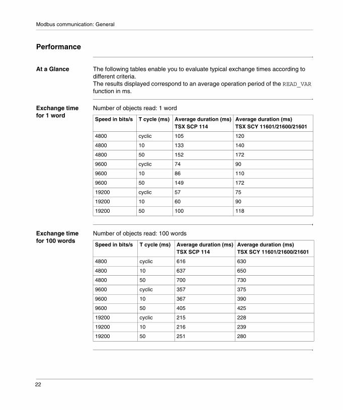
Performance
At a Glance The following tables enable you to evaluate typical exchange times according to different criteria.The results displayed correspond to an average operation period of the READ_VAR function in ms.
Exchange time for 1 word
Number of objects read: 1 word
Exchange time for 100 words
Number of objects read: 100 words
Speed in bits/s T cycle (ms) Average duration (ms)TSX SCP 114
Average duration (ms)TSX SCY 11601/21600/21601
4800 cyclic 105 120
4800 10 133 140
4800 50 152 172
9600 cyclic 74 90
9600 10 86 110
9600 50 149 172
19200 cyclic 57 75
19200 10 60 90
19200 50 100 118
Speed in bits/s T cycle (ms) Average duration (ms)TSX SCP 114
Average duration (ms)TSX SCY 11601/21600/21601
4800 cyclic 616 630
4800 10 637 650
4800 50 700 730
9600 cyclic 357 375
9600 10 367 390
9600 50 405 425
19200 cyclic 215 228
19200 10 216 239
19200 50 251 280
22
Modbus communication: General
Operating Mode
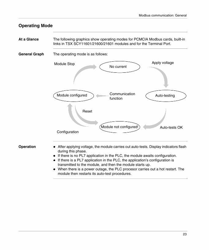
At a Glance The following graphics show operating modes for PCMCIA Modbus cards, built-in links in TSX SCY11601/21600/21601 modules and for the Terminal Port.
General Graph The operating mode is as follows:
Operation � After applying voltage, the module carries out auto-tests. Display indicators flash during this phase.
� If there is no PL7 application in the PLC, the module awaits configuration.� If there is a PL7 application in the PLC, the application’s configuration is
transmitted to the module, and then the module starts up.� When there is a power outage, the PLC procesor carries out a hot restart. The
module then restarts its auto-test procedures.
No current
Module configured
Module not configured!
Auto-testingCommunicationfunction
Auto-tests OK
Reset
Module Stop
Configuration
Apply voltage
23

Modbus communication: General
24

2
Configuring Modbus communicationIntroduction
Subject of Chapter
This Chapter describes the Configuration process during set-up of Modbus communication.
What’s in this Chapter?
This chapter contains the following topics:
Topic Page
How to access the Modbus PCMCIA card parameters 26
How to access the terminal port parameters 27
How to Access Parameters for TSX SCY 11601/21600/21601 Modules 28
Modbus Configuration Screen 29
Accessible Modbus Functions 30
Application linked Modbus Parameters 31
Modbus Parameters relating to transmission 33
25
Modbus configuration
How to access the Modbus PCMCIA card parameters
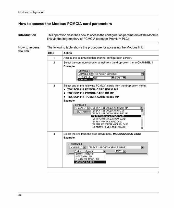
Introduction This operation describes how to access the configuration parameters of the Modbus link via the intermediary of PCMCIA cards for Premium PLCs.
How to access the link
The following table shows the procedure for accessing the Modbus link:
Step Action
1 Access the communication channel configuration screen.
2 Select the communication channel from the drop-down menu CHANNEL 1Example
3 Select one of the following PCMCIA cards from the drop-down menu:� TSX SCP 111 PCMCIA CARD RS232 MP� TSX SCP 112 PCMCIA CARD BC MP� TSX SCP 114 PCMCIA CARD RS485 MPExample
4 Select the link from the drop-down menu MODBUS/JBUS LINK:Example
CHANNEL 1 CHANNEL 1
(No PCMCIA submodule)
(Link not configured) MASTCHANNEL 0CHANNEL 1
CHANNEL 1 CHANNEL 1
TSX SCP 114 PCMCIA CARD RS485 MP
(Link not configured) MASTTSX SCP 112 PCMCIA CARD BC MPTSX SCP 114 PCMCIA CARD RS485 MPTSX FPP 20 PCMCIA FIPWAY CARDTSX FPP 200 PCMCIA FIPWAY CARDTSX FPP 10 PCMCIA FIPIO CARDTSX MBP 100 PCMCIA MODBUS+ CARDTSX MDM 10 PCMCIA MODEM CARD
CHANNEL 1:
MAST(Link not configured)
CHANNEL 1 TSX SCP 114 PCMCIA CARD RS 485 MP
(Link not configured)UNI-TELWAY LINKCHARACTER MODE LINKMODBUS/JBUS LINK
26

Modbus configuration
How to access the terminal port parameters
Introduction This operation describes how to access the configuration parameters of the Modbus link via the intermediary of the terminal port of the Micro PLC.
How to access the link
The following table shows the procedure for accessing the Modbus link:
Step Action
1 Access the communication channel configuration screen.
2 Select the link from the drop-down menu MODBUS/JBUS LINK:Example
VOIE 0:
MASTUNI-TELWAY LINK
CHANNEL 0 Terminal Port
UNI-TELWAY LINKCHARACTER MODE LINKMODBUS/JBUS LINK
27
Modbus configuration
How to Access Parameters for TSX SCY 11601/21600/21601 Modules
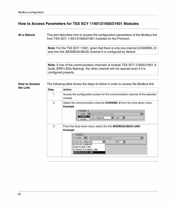
At a Glance This part describes how to access the configuration parameters of the Modbus link from TSX SCY 11601/21600/21601 modules for the Premium.
How to Access the Link
The following table shows the steps to follow in order to access the Modbus link:
������For the TSX SCY 11601, given that there is only one channel (CHANNEL 0) and one link (MODBUS/JBUS) channel 0 is configured by default.
������If one of the communication channels of module TSX SCY 21600/21601 is faulty (ERR LEDs flashing), the other channel will not operate even if it is configured properly.
Step Action
1 Access the configuration screen for the communication channel of the selected module
2 Select the communication channel CHANNEL 0 from the drop-down menuExample
3 From the drop-down menu select the link MODBUS/JBUS LINK:Example
CHANNEL 0CHANNEL 0
(No PCMCIA sub-module)
(Link not configured) MASTCHANNEL 0CHANNEL 1
CHANNEL 1:
MAST(Link not configured)
CHANNEL 0 (No PCMCIA sub-module)
(Link not configured)UNI-TELWAY LINKCHARACTER MODE LINKMODBUS/JBUS LINK
28
Modbus configuration
Modbus Configuration Screen
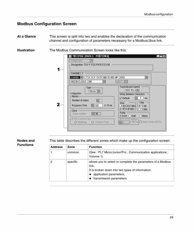
At a Glance This screen is split into two and enables the declaration of the communication channel and configuration of parameters necessary for a Modbus/Jbus link.
Illustration The Modbus Communication Screen looks like this:
Nodes and Functions
This table describes the different zones which make up the configuration screen:
�������������������� ����������
Configuration
Designation: TSX P 5725 PROCESSOR
Configuration
CHANN TSX SCP 114 PCMIA RS485 MP CARD
CHANNEL 1:
MODBUS/JBUS LINK MAST
Master 9600 Bits/s
3
100
98
Type
Master
Slave
(PSR) Current LoopMultidrop Point-to-Point
Slave number
Transmission Speed
Delay between characters
4
Data Stop
msDefaultNumber of retries
Response Time X 10 ms 1 bit 2 bits
ASCII (7 bits)RTU (8 bits)
ParityEven Odd None
0 RTS / CTS Delay
X100 ms Data Carrier (DCD)
�
�
Address Zone Function
1 common (See : PL7 Micro/Junior/Pro ; Communication applications ; Volume 1)
2 specific allows you to select or complete the parameters of a Modbus link.It is broken down into two types of information:� application parameters,� transmission parameters.
29

Modbus configuration
Accessible Modbus Functions
At a Glance Depending on the communication media chosen, certain parameters cannot be modified. These are grayed out.
Accessible Functions
The summary table below shows the various possible choices:
Specific Functions
The additional Immediate server function is only available where a TSX SCP 114 card has been inserted into TSX SCY 21600/21601 modules.
Functions SCP 111 SCP 112 SCP 114 SCY 11601/21600/21601
Terminal Port
Master Yes Yes Yes Yes Yes*
Slave Yes Yes Yes Yes Yes
(PSR) Current Loop No Yes No No No
Transmission Speed Yes Yes Yes Yes Yes
Delay between characters Yes Yes Yes Yes Yes
Data � ASCII� RTU
� ASCII� RTU
� ASCII� RTU
� ASCII� RTU
RTU only
Stop � 1 bit� 2 bits
� 1 bit� 2 bits
� 1 bit� 2 bits
� 1 bit� 2 bits
� 1 bit� 2 bits
Parity � odd� even� none
� odd� even� none
� odd� even� none
� odd� even� none
� odd� even� none
RTS/CTS delay Yes No No No No
Data Carrier (DCD) Management
Yes No No No No
*Only on TSX 37-10/21/22
������In the �����window for the Terminal Port, both options are possible but only the RTU format can function through the Terminal Port.
30

Modbus configuration
Application linked Modbus Parameters
At a Glance After configuring the communication channel, you need to enter the application parameters.
These are split into four windows:� the Type window,� the Master window,� the Slave window,� and the (PSR) Current Loopwindow.
Type Parameter The window looks like this:
It enables you to select the type of Modbus Protocol the module uses:� Master: selects Modbus Master where the station is master,� Slave: selects Modbus Slave where the station is slave,� Immediate Server: allows UNI-TE requests to be directed to the SERVER
function and not to the processor’s main server.
������The ������� �����parameter requires the SERVER (PL7 Micro/Junior/Pro ; Communication applications ; Volume 1) communication function to be programmed in PL7.It is valid until the box is checked.
Master Type
Slave Type
Immediate server
31
Modbus configuration
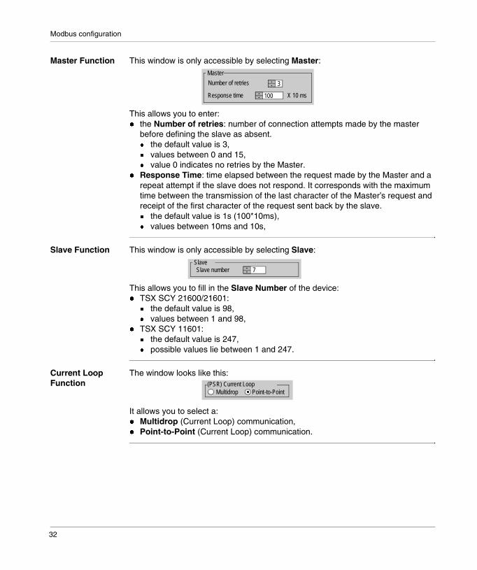
Master Function This window is only accessible by selecting Master:
This allows you to enter:� the Number of retries: number of connection attempts made by the master
before defining the slave as absent.� the default value is 3,� values between 0 and 15,� value 0 indicates no retries by the Master.
� Response Time: time elapsed between the request made by the Master and a repeat attempt if the slave does not respond. It corresponds with the maximum time between the transmission of the last character of the Master’s request and receipt of the first character of the request sent back by the slave.� the default value is 1s (100*10ms),� values between 10ms and 10s,
Slave Function This window is only accessible by selecting Slave:
This allows you to fill in the Slave Number of the device:� TSX SCY 21600/21601:
� the default value is 98,� values between 1 and 98,
� TSX SCY 11601:� the default value is 247,� possible values lie between 1 and 247.
Current Loop Function
The window looks like this:
It allows you to select a:� Multidrop (Current Loop) communication,� Point-to-Point (Current Loop) communication.
3
100
Master
Number of retries
Response time X 10 ms
7 Slave
Slave number
(PSR) Current LoopMultidrop Point-to-Point
32

Modbus configuration
Modbus Parameters relating to transmission
At a Glance After configuring the communication channel, you need to enter the transmission parameters.
These are split into six windows:� the Transmission speed window,� the Delay between characters window,� the windows specific to Data and Stop,� the Parity window,� the RTS/CTS delay window.
Transmission Speed
The window looks like this:
This window is used to select the transmission speed of the Modbus protocol used by the module, and is compliant with the other devices:� the default speed is 9600 bits/s,� the other speeds available are 1200, 2400, 9600 and 19200 bits/s,� speeds of 300 and 600 bits/s are only available with the PCMCIA card
TSX SCP 111.
9600 Bits/s Transmission Speed
33

Modbus configuration
Delay between characters
The window looks like this:
This is the end delimiter detection delay plus the maximum time between two characters received. It is managed when the PLC is receiving messages, whether it be a master or slave.
You are advised to use the default values on configurations that do not have a modem or other intermediary device. Otherwise, you must use higher values.
The table below gives the maximum values of the delay between characters depending on the transmission speed:
������The default value depends on the transmission speed selected.
������There is one ����������� on the ’Delay between characters’ value on channel 0 of � �� �������������������� modules (see table below).
Speed (bits/s) Max. delay between characters (ms)
Max. delay between characters (number of characters)
1200 212 23
2400 106 23
4800 53 23
9600 26 23
19200 13 22
Delay between characters
4 msDefault
34

Modbus configuration
Data The window looks like this:
The Data field can be used to enter the type of coding used for Modbus communication. This field is to be configured as a function of the other devices:� RTU mode:
� the characters are coded on 8 bits,� the start and end of frame delimiters are detected by a silence of 3.5
characters,� frame integrity is checked using the CRC checksum contained in the frame.
� ASCII mode:� the characters are coded on 7 bits,� the start delimiter is detected by receiving the characters ":" or by a silence
longer than the delay between characters.The end delimiter is detected by a CR and LF (carriage return and line feed) or by a silence longer than the delay between characters.
Stop The window looks like this:
The Stop field is used to enter the number of stop bits used to communicate on Modbus. The possible values are 1 or 2 stop bits. This field is to be configured as a function of the other devices.
Parity The window looks like this:
This field is used to define whether or not a parity bit is to be added, and, if so , what its type will be. The possible values are Even, Odd or none (Even by default). This field is to be configured as a function of the other devices.
������The value 1000 in ASCII mode corresponds to an infinite delay between characters.
DataASCII (7 bits)RTU (8 bits)
������The default value is 1 stop bit.
Stop 1 bit 2 bits
ParityEven Odd None
35
Modbus configuration
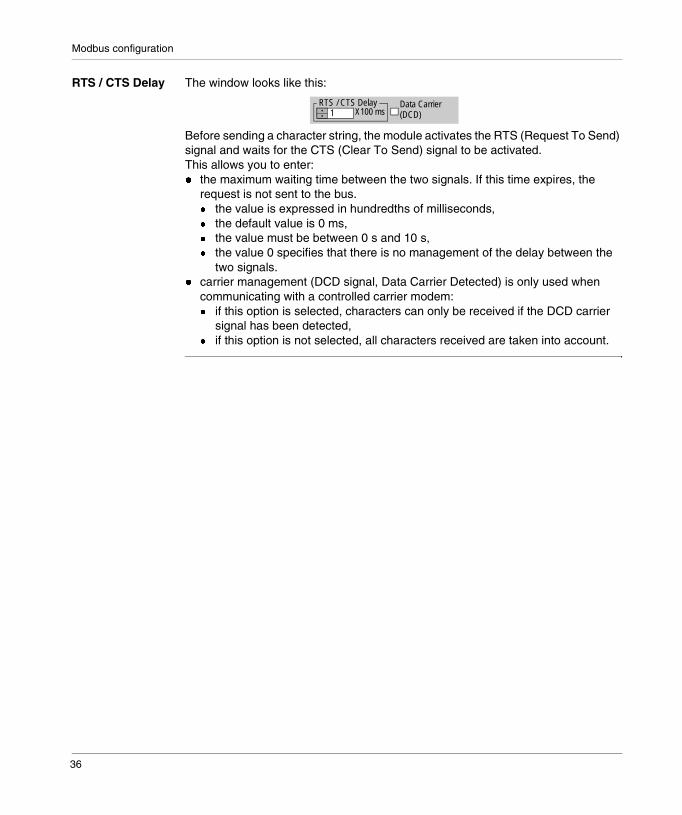
RTS / CTS Delay The window looks like this:
Before sending a character string, the module activates the RTS (Request To Send) signal and waits for the CTS (Clear To Send) signal to be activated.This allows you to enter:� the maximum waiting time between the two signals. If this time expires, the
request is not sent to the bus. � the value is expressed in hundredths of milliseconds,� the default value is 0 ms,� the value must be between 0 s and 10 s,� the value 0 specifies that there is no management of the delay between the
two signals.� carrier management (DCD signal, Data Carrier Detected) is only used when
communicating with a controlled carrier modem:� if this option is selected, characters can only be received if the DCD carrier
signal has been detected,� if this option is not selected, all characters received are taken into account.
1 RTS / CTS Delay
X100 msData Carrier (DCD)
36

3
Programming Modbus communicationIntroduction
Subject of section
This section describes the Programming process during set-up of Modbus communication.
What’s in this Chapter?
This chapter contains the following topics:
Topic Page
Modbus Master Communication Function 38
Modbus Slave Communication Function 40
Using the SEND_REQ communication function 42
Example 1: SEND_REQ function with Echo request 43
Example 2: SEND_REQ function with Word read request 44
Example 3: SEND_REQ Function with Bit Read Request 46
Example 4: READ_VAR function for reading bits 48
37
Modbus programming
Modbus Master Communication Function
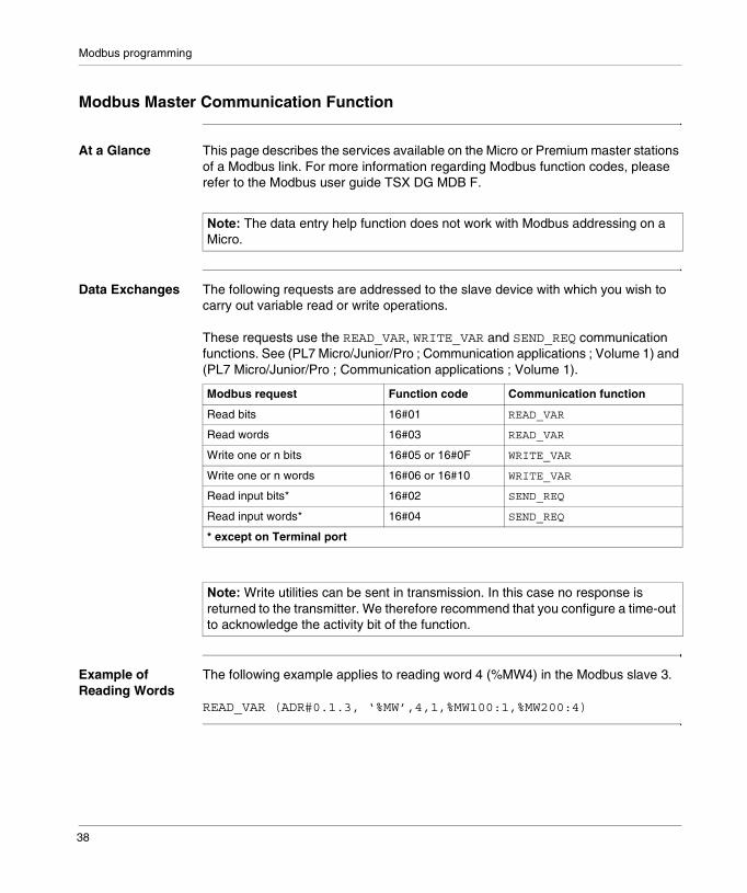
At a Glance This page describes the services available on the Micro or Premium master stations of a Modbus link. For more information regarding Modbus function codes, please refer to the Modbus user guide TSX DG MDB F.
Data Exchanges The following requests are addressed to the slave device with which you wish to carry out variable read or write operations.
These requests use the READ_VAR, WRITE_VAR and SEND_REQ communication functions. See (PL7 Micro/Junior/Pro ; Communication applications ; Volume 1) and (PL7 Micro/Junior/Pro ; Communication applications ; Volume 1).
Example of Reading Words
The following example applies to reading word 4 (%MW4) in the Modbus slave 3.
READ_VAR (ADR#0.1.3, ‘%MW’,4,1,%MW100:1,%MW200:4)
������The data entry help function does not work with Modbus addressing on a Micro.
Modbus request Function code Communication function
Read bits 16#01 READ_VAR
Read words 16#03 READ_VAR
Write one or n bits 16#05 or 16#0F WRITE_VAR
Write one or n words 16#06 or 16#10 WRITE_VAR
Read input bits* 16#02 SEND_REQ
Read input words* 16#04 SEND_REQ
* except on Terminal port
������Write utilities can be sent in transmission. In this case no response is returned to the transmitter. We therefore recommend that you configure a time-out to acknowledge the activity bit of the function.
38

Modbus programming
Diagnostics and Maintenance
The diagnostics and maintenance information of Modbus slaves uses the SEND_REQ communication function. (See : PL7 Micro/Junior/Pro ; Communication applications ; Volume 1)
Modbus request Function code / sub-function code Communication function
Exception status 16#07 SEND_REQ
Diagnostics 16#08 / 16#xx SEND_REQ
Event counter 16#0B SEND_REQ
Connection event 16#0C SEND_REQ
Slave identification 16#11 SEND_REQ
39
Modbus programming
Modbus Slave Communication Function
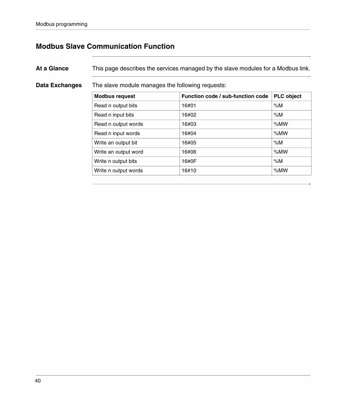
At a Glance This page describes the services managed by the slave modules for a Modbus link.
Data Exchanges The slave module manages the following requests:
Modbus request Function code / sub-function code PLC object
Read n output bits 16#01 %M
Read n input bits 16#02 %M
Read n output words 16#03 %MW
Read n input words 16#04 %MW
Write an output bit 16#05 %M
Write an output word 16#06 %MW
Write n output bits 16#0F %M
Write n output words 16#10 %MW
40

Modbus programming
Diagnostics and Maintenance
The diagnostics and maintenance information which are accessible from a Modbus link are shown below:
Designation Function code / sub-function code
Read exception status 16#07
Echo 16#08 / 16#00
Initialize module 16#08 / 16#01
Read the diagnostic registers of the PLC 16#08 / 16#02
Change end of frame delimiter (ASCII mode) 16#08 / 16#03
Switch to listening mode 16#08 / 16#04
Reset counters 16#08 / 16#0A
Number of messages received without CRC error 16#08 / 16#0B
Number of frames received with CRC error 16#08 / 16#0C
Number of exceptional responses 16#08 / 16#0D
Number of messages addressed to the PLC 16#08 / 16#0E
Number of broadcast messages received 16#08 / 16#0F
Number of correct responses 16#08 / 16#10
Number of messages received in listening mode 16#08 / 16#11
Number of invalid characters received 16#08 / 16#12
Read event counter 16#0B
Read connection event 16#0C
Read identificationNote: The slave request response returns the same elements as the UNI-TE identification request (see the subchapter General Use Requests in the TSX DR NET manual).
16#11
41

Modbus programming
Using the SEND_REQ communication function
At a Glance The UNI-TE Action-object request (request code 16#9F) is used to transmit all Modbus (See : PL7 Micro/Junior/Pro ; Communication applications ; Volume 1) functions.
After executing this request, the report is always 16#CF00.To check the exchange, it is also necessary to test the content of the first word in the reception table.
Possible values of the first word:� 0: indicates that the exchange has been performed,� 1: indicates that the exchange has not been performed,
The transmission buffer should contain the following information:� first word:
� Byte 0: function code,� Byte 1: sub-function code,
� second word: Modbus function identifier, which is always 16#0296� third word = 0: reserved� fourth word: Modbus function parameters� fifth word: Modbus function parameters� n th word: Modbus function parameters
������This function is not available in Modbus master mode on the Terminal port.
42

Modbus programming
Example 1: SEND_REQ function with Echo request
At a Glance This example concerns the Echo diagnostics function. This function requests that the interrogated slave return the message sent by the master in full.
Question The communication function is as follows:SEND_REQ(ADR#0.1.x,16#9F,%MW10:10,%MW50:30,%MW100:4)
Before sending the function it is necessary to initialize the following words:
Response The slave response, contained in the %MW50:30 reception buffer, is of type:
Words Value Description
%MW10 := 16#0008 corresponds to the Echo function (byte 0 = 16#08, byte 1 =16#00
%MW11 := 16#0296 corresponds to the identification of the Modbus function
%MW12 := 0 reserved
%MW13 := 16#1234 corresponds to the Echo function parameter. For this example, the slave must return the value 16#1234
%MW103 := 8 (bytes) length of the data to be transmitted in bytes
%MW50 %MW51 Description
:= 0 if action taken := 16#0008 corresponds to the Echo function (byte 0 = 16#08, byte 1 =16#00)%MW52 to %MW79 contain the Modbus response data. For this example %MW52:= 1234
:= 1 if action not taken := 16#0007 incorrect request parameters
:= 16#0004 incorrect question parameters
:= 16#0688 byte 0 =16#80 + function code (16#08 for Echo)byte 1 = 16#06 Modbus error code (the slave is busy)
:= 16#0188 byte 0 =16#80 + function code (16#08 for Echo)byte 1 = 16#01 Modbus error code (the function is unknown)
:= 16#0388 byte 0 =16#80 + function code (16#08 for Echo)byte 1 = 16#03 Modbus error code (the data is invalid)
43
Modbus programming
Example 2: SEND_REQ function with Word read request
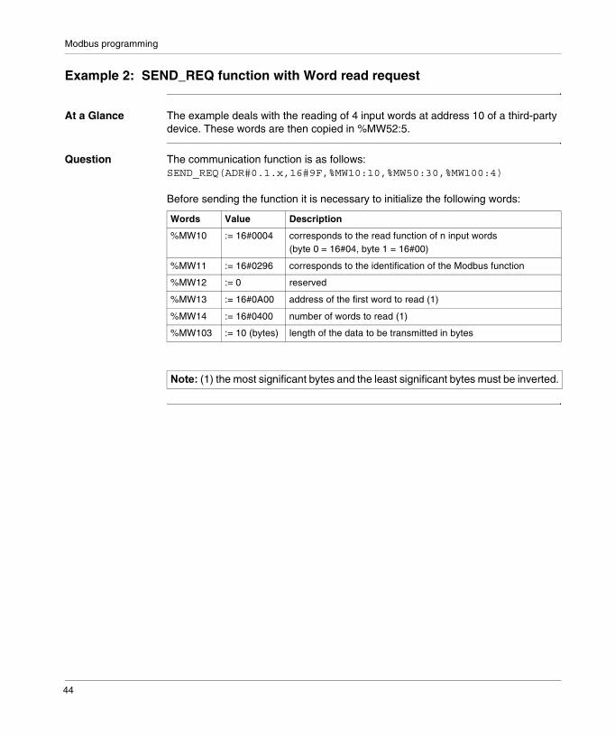
At a Glance The example deals with the reading of 4 input words at address 10 of a third-party device. These words are then copied in %MW52:5.
Question The communication function is as follows:SEND_REQ(ADR#0.1.x,16#9F,%MW10:10,%MW50:30,%MW100:4)
Before sending the function it is necessary to initialize the following words:
Words Value Description
%MW10 := 16#0004 corresponds to the read function of n input words (byte 0 = 16#04, byte 1 = 16#00)
%MW11 := 16#0296 corresponds to the identification of the Modbus function
%MW12 := 0 reserved
%MW13 := 16#0A00 address of the first word to read (1)
%MW14 := 16#0400 number of words to read (1)
%MW103 := 10 (bytes) length of the data to be transmitted in bytes
������(1) the most significant bytes and the least significant bytes must be inverted.
44

Modbus programming
Response The slave response, contained in the %MW50:30 reception buffer, is of type:
%MW50 %MW51 Description
:= 0 if action taken := 16#0004 corresponds to the read function of n input words (byte 0 = 16#04, byte 1 = 16#00)%MW52 to %MW79 contain the Modbus response data:� %MW52:= PF0 0A
� byte 0 = 16#0A: length received in bytes (10 bytes)� byte 1 = PF0: most significant byte of first word
� %MW53:= PF1 pf0
� byte 0 = pf0: least significant byte of first word
� byte 1 = PF1: most significant byte of second word
� %MW54:= PF2 pf1
� byte 0 = pf1: least significant byte of second word
� byte 1 = PF2: most significant byte of third word
:= 1 if action not taken := 16#0007 incorrect request parameters
:= 16#0004 incorrect question parameters
:= 16#0688 byte 0 =16#80 + function code (16#08 for Echo)byte 1 = 16#06 Modbus error code (the slave is busy)
:= 16#0188 byte 0 =16#80 + function code (16#08 for Echo)byte 1 = 16#01 Modbus error code (the function is unknown)
:= 16#0388 byte 0 =16#80 + function code (16#08 for Echo)byte 1 = 16#03 Modbus error code (the data is invalid)
������To retrieve the words read, use the instruction ROR1_ARB.
45
Modbus programming
Example 3: SEND_REQ Function with Bit Read Request
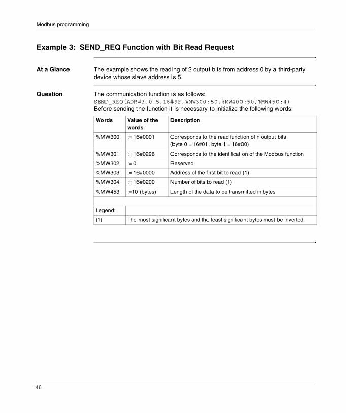
At a Glance The example shows the reading of 2 output bits from address 0 by a third-party device whose slave address is 5.
Question The communication function is as follows:SEND_REQ(ADR#3.0.5,16#9F,%MW300:50,%MW400:50,%MW450:4)Before sending the function it is necessary to initialize the following words:
Words Value of the words
Description
%MW300 := 16#0001 Corresponds to the read function of n output bits (byte 0 = 16#01, byte 1 = 16#00)
%MW301 := 16#0296 Corresponds to the identification of the Modbus function
%MW302 := 0 Reserved
%MW303 := 16#0000 Address of the first bit to read (1)
%MW304 := 16#0200 Number of bits to read (1)
%MW453 :=10 (bytes) Length of the data to be transmitted in bytes
Legend:
(1) The most significant bytes and the least significant bytes must be inverted.
46

Modbus programming
Response The slave response, contained in the %MW400:50 reception buffer, is of type:
Word Value Description
%MW400 := 0 if action taken:= 1 if action not taken
%MW401if %MW400:= 0
:= 16#0001 Corresponds to the read function of n output bits (byte 0 = 16#01, byte 1 = 16#00)
%MW401if %MW400:= 1
:= 16#0007 Incorrect request parameters
:= 16#0004 Incorrect question parameters
:= 16#0681 Byte 0 =16#80 + function code (16#01)Byte 1 = � 16#06 Modbus error code (the slave is busy)� 16#01 Modbus error code (the function is unknown)� 16#03 Modbus error code (the data is invalid)
%MW402 := 16#xx01 Contains the Modbus response data:Byte 0 = 16#01: length received in bytes (1 byte)Byte 1 = 16#xx: value of the bits For example, if bit 1 = 1 and bit 2 = 1, then byte 1 = 16#03
47

Modbus programming
Example 4: READ_VAR function for reading bits
General Exchanges with Modbus slave devices are programmed using the READ_VAR and WRITE_VAR communication functions only (the SEND_REQ function is not supported on the TER port).
Example with READ_VAR
Description of the objects used in the example:
Example of the program:
!(*���� �������������������������������������������*)
IF %MW0:X0 AND NOT %M20 THEN%MW200:4:=0;%MW202:=50;SET %M20;READ_VAR(ADR#0.0.37,’%M’,0,8,%MW100:10,%MW200:4);(*8 bits %M0..%M7 are read in the slave 37 and placed in the %MW100 word of the master*)END_IF;
!(*����������������������*)
IF %M20 AND NOT %MW200:X0 THENINC %MW204;RESET %M20;RESET %MW0:X0;IF %MW201=0 THEN INC %MW205;SET %M30;ELSE INC %MW206;%MW207:=%MW201;RESET %M30;END_IF;
Object Description
%MW0:X0 Request transmission request
%M20 Requesting
%MW100:10 Reception buffer
%MW200..203 Report zone:
%MW200 Session number and activity bit (X0)
%MW201 Error code
%MW202 Time-out in units of 10 ms
%M30 Bit set to 1 after a successful exchange
%MW204 Counter of requests sent
%MW205 Counter of successful requests
%MW206 Counter of unsuccessful requests
%MW207 Error code of the last unsuccessful request
48
4
Debugging Modbus communicationIntroduction
Subject of Chapter
This Chapter describes the Debugging process during set-up of Modbus communication.
What’s in this Chapter?
This chapter contains the following topics:
Topic Page
Modbus debug screen 50
Modbus Master debugging screen 51
Debug screen in Modbus slave type 52
How to test a communication channel 53
49

Modbus debugging
Modbus debug screen
At a Glance This screen is split into two and enables the declaration of the communication channel and gives access to the debug parameters for a Modbus link.
Illustration The Modbus Communication Screen looks like this:
Nodes and Functions
This table describes the different zones which make up the debug screen:
CHANN
�������������������� ����������
CHANNEL 1
Designation: TSX P 5735 PROCESSOR Version: 3.0
TSX SCP 111 RS232 MP PCMCIA CARD
MODBUS/JBUS LINK
Debug
Response reception
DIAG...
ASCII Hexa
Received without CRC error
Identification
Enter request
Counters
Received with exception codeReceived in broadcast modeSlave BUSY or LOM Character error
Sent with NACKMessage for the CPUReceived with CRC error
1
0
00 0
0
0
0Type:
DIAG...
Reset counters
0Slave
Slave
Channel test
�
�
Address Zone Function
1 common (See : PL7 Micro/Junior/Pro ; Communication applications ; Volume 1)
2 specific gives access to the debug parameters of a Modbus link.It differs according to the type of Modbus function configured:� either Modbus master,� or Modbus slave.
50
Modbus debugging
Modbus Master debugging screen
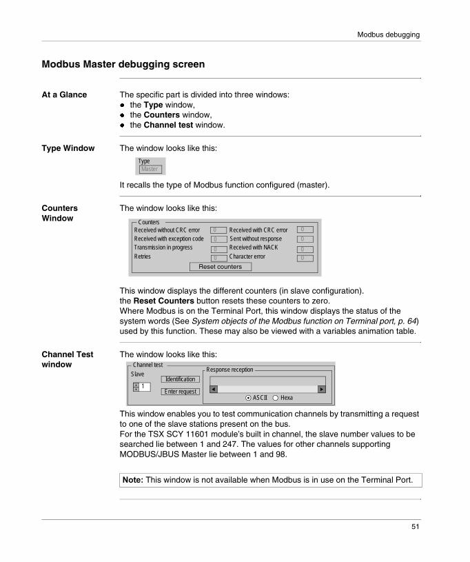
At a Glance The specific part is divided into three windows:� the Type window,� the Counters window,� the Channel test window.
Type Window The window looks like this:
It recalls the type of Modbus function configured (master).
Counters Window
The window looks like this:
This window displays the different counters (in slave configuration).the Reset Counters button resets these counters to zero.Where Modbus is on the Terminal Port, this window displays the status of the system words (See System objects of the Modbus function on Terminal port, p. 64) used by this function. These may also be viewed with a variables animation table.
Channel Test window
The window looks like this:
This window enables you to test communication channels by transmitting a request to one of the slave stations present on the bus.For the TSX SCY 11601 module’s built in channel, the slave number values to be searched lie between 1 and 247. The values for other channels supporting MODBUS/JBUS Master lie between 1 and 98.
Type Master
Received without CRC error Counters
Received with exception codeTransmission in progressRetries Character error
Received with NACKSent without responseReceived with CRC error
0
00 0
0
0
0
Reset counters
0
������This window is not available when Modbus is in use on the Terminal Port.
Response reception
ASCII Hexa
Identification
Enter request1
Slave
Channel test
51
Modbus debugging
Debug screen in Modbus slave type
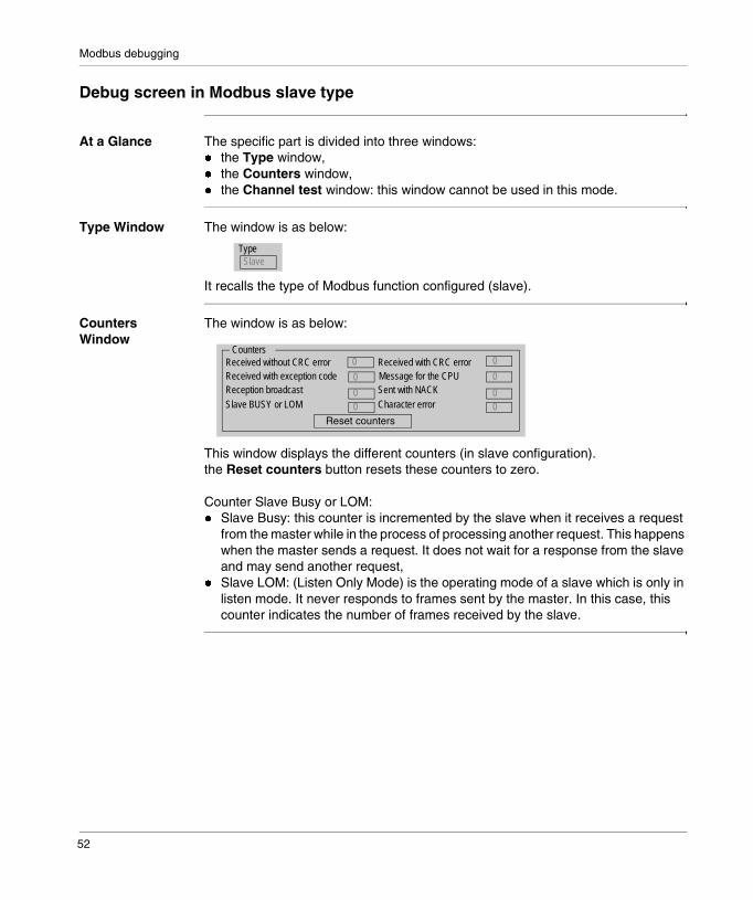
At a Glance The specific part is divided into three windows:� the Type window,� the Counters window,� the Channel test window: this window cannot be used in this mode.
Type Window The window is as below:
It recalls the type of Modbus function configured (slave).
Counters Window
The window is as below:
This window displays the different counters (in slave configuration).the Reset counters button resets these counters to zero.
Counter Slave Busy or LOM:� Slave Busy: this counter is incremented by the slave when it receives a request
from the master while in the process of processing another request. This happens when the master sends a request. It does not wait for a response from the slave and may send another request,
� Slave LOM: (Listen Only Mode) is the operating mode of a slave which is only in listen mode. It never responds to frames sent by the master. In this case, this counter indicates the number of frames received by the slave.
Type Slave
Received without CRC error Counters
Received with exception code Reception broadcastSlave BUSY or LOM Character error
Sent with NACKMessage for the CPUReceived with CRC error
0
00 0
0
0
0
Reset counters
0
52

Modbus debugging
How to test a communication channel
Introduction This page shows the procedure for testing a communication channel from the debugging screen.
How to identify a station
The following procedure is used to identify a designated station.
Step Actions
1 Select the address of the slave to be interrogated using the Slave field.
2 Click on the Identification button.
ResultThe response appears in the Receive Response window:
Receive response
Ascii Hex.
.....TSX 3721...!0....
53
Modbus debugging
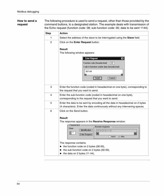
How to send a request
The following procedure is used to send a request, other than those provided by the command buttons, to a designated station. The example deals with transmission of the Echo request (function code: 08; sub-function code: 00; data to be sent 1144).
Step Action
1 Select the address of the slave to be interrogated using the Slave field.
2 Click on the Enter Request button.
ResultThe following window appears:
3 Enter the function code (coded in hexadecimal on one byte), corresponding to the request that you want to send.
4 Enter the sub-function code (coded in hexadecimal on one byte), corresponding to the request that you want to send.
5 Enter the data to be sent by encoding all the data in hexadecimal on 2 bytes (4 characters). Enter the data continuously without any intervening spaces.
6 Click on the Send button.
ResultThe response appears in the Receive Response window:
The response contains:� the function code on 2 bytes (08 00),� the sub-function code on 2 bytes (00 00),� the data on 2 bytes (11 44),
�������������
Function code (hexadecimal)
Code in functions and/or data (hexadecimal)
Send
03
Cancel
001144
Receive response
Ascii Hex.
Identification
Enter Request1
Slave
Channel test
08 00 00 00 11 44
54

5
Language objects associated with Modbus communicationIntroduction
Subject of this Section
This Chapter introduces the language objects linked to Modbus communication.
What’s in this Chapter?
This chapter contains the following topics:
Topic Page
Implicit exchange language object for a Modbus function 56
Explicit exchange language objects for a Modbus function 58
Explicit exchange management and report 61
Language objects associated with the configuration 62
System objects of the Modbus function on Terminal port 64
55
Modbus language objects
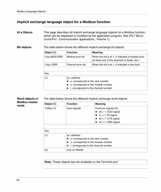
Implicit exchange language object for a Modbus function
At a Glance This page describes all implicit exchange language objects for a Modbus function, which can be displayed or modified by the application program. See (PL7 Micro/Junior/Pro ; Communication applications ; Volume 1).
Bit objects The table below shows the different implicit exchange bit objects.
Word objects in Modbus master mode
The table below shows the different implicit exchange word objects.
Object (1) Function Meaning
%Ixy.MOD.ERR Module error bit When this bit is at 1, it indicates a module error (at least one of the channels is faulty, etc.)
%Ixy.i.ERR Channel error bit When this bit is at 1, it indicates a line fault.
Key
(1) xy.i address� x: corresponds to the rack number� y: corresponds to the module number� i: corresponds to the channel number
Object (1) Function Meaning
%IWxy.i.0 Input signals Common signals (2):� x0 = 1: DCD signal� x1 = 1: RI signal� x2 = 1: CTS signal� x3 = 1: DSR signal
Key
(1) xy.i address� x: corresponds to the rack number� y: corresponds to the module number� i: corresponds to the channel number
(2) only on RS232
������These objects are not available on the Terminal port
56

Modbus language objects
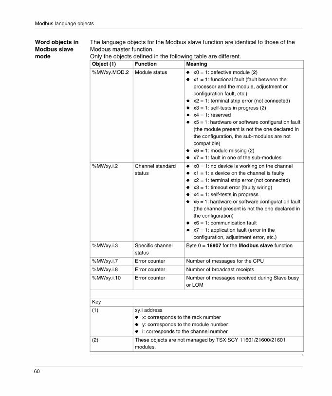
Word objects in Modbus slave mode
The language objects are identical to those of the Modbus master function. Only the objects defined in the following tables are different.
The table below shows the different implicit exchange word objects.
Object (1) Function Meaning
%IWxy.i.0 Input signals Specific data� x8 = 1: listen only mode
Key
(1) xy.i address� x: corresponds to the rack number� y: corresponds to the module number� i: corresponds to the channel number
������These objects are not available on the Terminal port
57

Modbus language objects
Explicit exchange language objects for a Modbus function
At a Glance This page describes all explicit exchange language objects for a Modbus master function, which can be displayed or modified by the application program. See (PL7 Micro/Junior/Pro ; Communication applications ; Volume 1).
Word objects in master mode
The table below shows the different explicit exchange word objects.
Object (1) Function Meaning
%MWxy.MOD.2 Module status � x0 = 1: defective module (3)� x1 = 1: functional fault (fault between the
processor and the module, adjustment or configuration fault, etc.)
� x2 = 1: terminal strip error (not connected)� x3 = 1: self-tests in progress (3)� x4 = 1: reserved� x5 = 1: hardware or software configuration fault
(the module present is not the one declared in the configuration, the sub-modules are not compatible)
� x6 = 1: module missing (3)� x7 = 1: fault in one of the sub-modules
%MWxy.i.2 Channel standard status
� x0 = 1: no device is working on the channel� x1 = 1: a device on the channel is faulty� x2 = 1: terminal strip error (not connected)� x3 = 1: timeout error (faulty wiring)� x4 = 1: self-tests in progress� x5 = 1: hardware or software configuration fault
(the channel present is not the one declared in the configuration)
� x6 = 1: communication fault� x7 = 1: application fault (error in the
configuration, adjustment error, etc.)
%MWxy.i.3 Specific channel status
Byte 0 = 16#06 for the Modbus master function
%MWxy.i.4 Error counter (2) Number of responses received without CRC error
%MWxy.i.5 Error counter (2) Number of messages received with CRC error
%MWxy.i.6 Error counter (2) Number of responses received with an exception code
%MWxy.i.7 Error counter (2) Number of master messages sent without response
58

Modbus language objects
%MWxy.i.8 Error counter (2) Number of transmissions broadcast
%MWxy.i.9 Error counter (2) Number of receipts with NACK
%MWxy.i.10 Error counter (2) Number of master messages repeated
%MWxy.i.11 Error counter (2) Number of character errors
%MWxy.i.15 Command (2) � x0 = 1: Reset counter� x8 = 1: DTR signal ON (5)� x9 = 1: DTR signal OFF (5)� x14 = 1: change from Modbus to character
mode (modem) (4)� x15 = 1: change from character mode (modem)
to Modbus (4)
Key
(1) xy.i address� x: corresponds to the rack number� y: corresponds to the module number� i: corresponds to the channel number
(2) These objects are not available on the Terminal port
(3) These objects are not managed by TSX SCY 11601/21600/21601 modules.
(4) These objects are not available on the TSX SCY 11601 module.
(5) Modbus on RS232.
Object (1) Function Meaning
59
Modbus language objects
Word objects in Modbus slave mode
The language objects for the Modbus slave function are identical to those of the Modbus master function. Only the objects defined in the following table are different.Object (1) Function Meaning
%MWxy.MOD.2 Module status � x0 = 1: defective module (2)� x1 = 1: functional fault (fault between the
processor and the module, adjustment or configuration fault, etc.)
� x2 = 1: terminal strip error (not connected)� x3 = 1: self-tests in progress (2)� x4 = 1: reserved� x5 = 1: hardware or software configuration fault
(the module present is not the one declared in the configuration, the sub-modules are not compatible)
� x6 = 1: module missing (2)� x7 = 1: fault in one of the sub-modules
%MWxy.i.2 Channel standard status
� x0 = 1: no device is working on the channel� x1 = 1: a device on the channel is faulty� x2 = 1: terminal strip error (not connected)� x3 = 1: timeout error (faulty wiring)� x4 = 1: self-tests in progress� x5 = 1: hardware or software configuration fault
(the channel present is not the one declared in the configuration)
� x6 = 1: communication fault� x7 = 1: application fault (error in the
configuration, adjustment error, etc.)
%MWxy.i.3 Specific channel status
Byte 0 = 16#07 for the Modbus slave function
%MWxy.i.7 Error counter Number of messages for the CPU
%MWxy.i.8 Error counter Number of broadcast receipts
%MWxy.i.10 Error counter Number of messages received during Slave busy or LOM
Key
(1) xy.i address� x: corresponds to the rack number� y: corresponds to the module number� i: corresponds to the channel number
(2) These objects are not managed by TSX SCY 11601/21600/21601 modules.
60
Modbus language objects
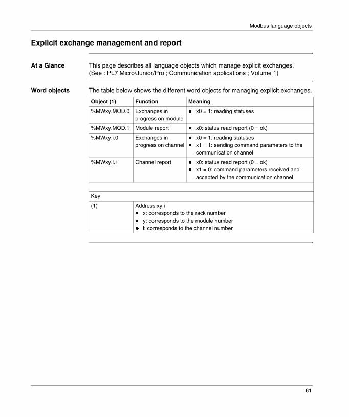
Explicit exchange management and report
At a Glance This page describes all language objects which manage explicit exchanges. (See : PL7 Micro/Junior/Pro ; Communication applications ; Volume 1)
Word objects The table below shows the different word objects for managing explicit exchanges.
Object (1) Function Meaning
%MWxy.MOD.0 Exchanges in progress on module
� x0 = 1: reading statuses
%MWxy.MOD.1 Module report � x0: status read report (0 = ok)
%MWxy.i.0 Exchanges in progress on channel
� x0 = 1: reading statuses� x1 = 1: sending command parameters to the
communication channel
%MWxy.i.1 Channel report � x0: status read report (0 = ok)� x1 = 0: command parameters received and
accepted by the communication channel
Key
(1) Address xy.i � x: corresponds to the rack number� y: corresponds to the module number� i: corresponds to the channel number
61

Modbus language objects
Language objects associated with the configuration
At a Glance This page describes all configuration language objects enabling Modbus communication which can be displayed by the application program.
Objects for the Modbus master function (where Terminal Port is inoperative)
The following table describes internal constants for the Modbus master function (except on the Terminal Port):
Object Function Meaning
%KWxy.i.0 Type Byte 0 = 16#06 for Modbus master functionByte 1: reserved
%KWxy.i.1 Speed / Format Byte 0 = speed� 128 = 300 bits/s, 129 = 600 bits/s
(only for TSX SCP 111)� 00 = 1200 bits/s, ..., 04 = 19200 bits/sByte 1 = format� x8: bit number (1 = 8 bits, 0 = 7 bits)� x9: parity management (1 = with, 0 = without)� x10: Parity Type (1 = odd, 0 = even)� x11: stop bit (1 = 1 bit, 0 = 2 bits)
%KWxy.i.2 Delay between characters
Value in ms from 2 ms to 10 000 ms
%KWxy.i.3 Wait Time Wait Time in ms from 10 ms to 10 000 ms
%KWxy.i.4 Retries and Signal Management
Byte 0 = number of retries (3 by default)Byte 1 = Signal Management� x8 = 1 if PSR signal management
(TSX SCP 112)� x10 = 1 if DCD Data Carrier management
(TSX SCP 111)
%KWxy.i.5 RTS / CTS Delay Delay time in hundredths of ms, only for TSX SCP 111 (default value 0 ms)
62
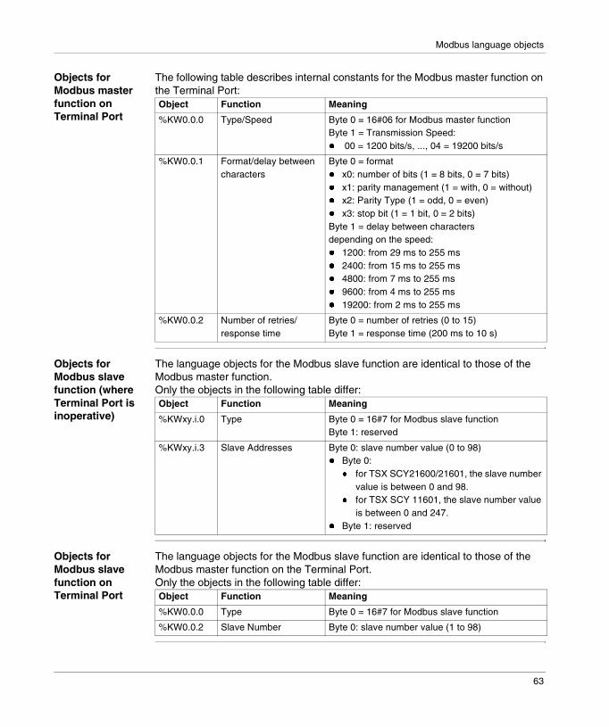
Modbus language objects
Objects for Modbus master function on Terminal Port
The following table describes internal constants for the Modbus master function on the Terminal Port:
Objects for Modbus slave function (where Terminal Port is inoperative)
The language objects for the Modbus slave function are identical to those of the Modbus master function.Only the objects in the following table differ:
Objects for Modbus slave function on Terminal Port
The language objects for the Modbus slave function are identical to those of the Modbus master function on the Terminal Port.Only the objects in the following table differ:
Object Function Meaning
%KW0.0.0 Type/Speed Byte 0 = 16#06 for Modbus master functionByte 1 = Transmission Speed:� 00 = 1200 bits/s, ..., 04 = 19200 bits/s
%KW0.0.1 Format/delay between characters
Byte 0 = format� x0: number of bits (1 = 8 bits, 0 = 7 bits)� x1: parity management (1 = with, 0 = without)� x2: Parity Type (1 = odd, 0 = even)� x3: stop bit (1 = 1 bit, 0 = 2 bits)Byte 1 = delay between charactersdepending on the speed:� 1200: from 29 ms to 255 ms� 2400: from 15 ms to 255 ms� 4800: from 7 ms to 255 ms� 9600: from 4 ms to 255 ms� 19200: from 2 ms to 255 ms
%KW0.0.2 Number of retries/response time
Byte 0 = number of retries (0 to 15)Byte 1 = response time (200 ms to 10 s)
Object Function Meaning
%KWxy.i.0 Type Byte 0 = 16#7 for Modbus slave functionByte 1: reserved
%KWxy.i.3 Slave Addresses Byte 0: slave number value (0 to 98)� Byte 0:
� for TSX SCY21600/21601, the slave number value is between 0 and 98.
� for TSX SCY 11601, the slave number value is between 0 and 247.
� Byte 1: reserved
Object Function Meaning
%KW0.0.0 Type Byte 0 = 16#7 for Modbus slave function
%KW0.0.2 Slave Number Byte 0: slave number value (1 to 98)
63

Modbus language objects
System objects of the Modbus function on Terminal port
At a Glance In Modbus mode on the Terminal port, the Micro uses the system objects below for the communication diagnostics.
Bit objects Table of bit objects
Word objects Table of word objects
Object Description
%S80 Global reset to 0 of the communication counters
%S81 Reset to 0 of the Modbus system words on Terminal port This system bit is set to 1 by the application and reset to 0 by the system
������The system words are also reset to 0 when there is a cold start (%S0 =1).
Objects Description
%SW100 Number of messages received without CRC error
%SW101 Number of messages received with CRC error
%SW102 Number of messages received with an exception code
%SW103 Number of master messages sent without response
%SW104 Number of transmissions broadcast
%SW102 Number of receipts with NACK
%SW106 Number of master messages repeated
%SW107 Number of character errors
64
II
Communication via ModemIntroduction
Subject of this part
This part introduces the principles of configuring and communicating using a TSX MDM 10 modem via PL7 software.
What’s in this Part?
This part contains the following chapters:
Chapter Chapter Name Page
6 Communication via Modem 67
7 Configuring Modem communication 87
8 Programming Modem communication 99
9 Debugging Modem communication 117
10 Language objects associated with Modem communication 121
11 Appendices 131
65

Communication via Modem
66
6
Communication via ModemIntroduction
Subject of this Chapter
This Chapter introduces communication using a TSX MDM 10 modem and its services.
What’s in this Chapter?
This chapter contains the following sections:
Section Topic Page
6.1 Introduction to communication via Modem 68
6.2 Characteristics 74
6.3 Setting up communication via Modem 78
67

General
6.1 Introduction to communication via Modem
Introduction
Subject of Section
This Section presents a summary description of communication using a TSX MDM 10 modem and its associated services.
What’s in this Section?
This section contains the following topics:
Topic Page
Modems 69
Standard configuration for communication via modem 70
Other configurations for communication via modem 71
Principles of communication between two stations 73
68

General
Modems
Introduction A large number of applications use communication via modem.
Communication via the TSX MDM 10 modem can be used to access remote stations using the switched public telephone network in order to carry out checks, diagnostics or long distance control.
Associated manuals
If you require further information you should consult the following manuals:
Title Description
Micro PLCs - Installation manual Hardware installation
Premium TSX PLCs - Installation manual Hardware installation
69

General
Standard configuration for communication via modem
Introduction The standard configuration allows for communication between stations or other devices connected to a switched telephone network.
Configuration and services
The following diagram shows the standard configuration for communication via modem and the different services.
Programming terminalTelephoneFax
Pocket size receiver
Sending back alarms and measurements
Variable exchangesCommandsAlarms and
measurements
ProgrammingDebuggingCommands
Switched telephone network
Remote station 1 Remote station n
70

General
Other configurations for communication via modem
Introduction From a local network station, it is possible to call a remote station on the switched telephone network via another station with a modem connection.
External CALL_MODEM function
A CALL_MODEM communication function is sent by a network station.
Once a link has been established, communication is possible in both directions while respecting transparency rules.
Moreover, a slave station on the switched telephone network can access the entire network architecture while respecting addressing rules.
Programmingterminal
MasterFIPWAY 1 network
Switched telephone network
Calling stationStation 1.3
Called stationStation 1.1
External CALL_MODEM functionCALL_MODEM(ADR#{1.1}0.1.SYS, ..
Address slave 1 and 2
71

General
Local CALL_MODEM function
A CALL_MODEM communication function is sent by the station supporting the TSX MDM 10 card.
Programmingterminal
Master
FIPWAY 1 network
Switchedtelephonenetwork
Station 1.3
Called stationStation 1.1
Address slave 1 and 2
Calling station
Local CALL_MODEM functionCALL_MODEM(ADR#0.1.SYS, ...
72

General
Principles of communication between two stations
Introduction The call direction is from station A to station B:
Operation The following table describes the different stages of communication between two stations:
Station Astation where call is to be made (transmitter)
Station Bcalled station
(receiver)
Switched telephone network
Phase Description
1 While idle, all modems are by default awaiting a possible connection request.
2 Station A sends a call request to number X on station B using AT commands (or using the CALL_MODEM communication function in the case of a PLC).
3 An exchange procedure between the modems results in the line being established point by point between station A and station B. Connection is established if the correct password is used (if password management is employed).
4 Stations A and B then dialog according to the protocol chosen on calling, whether Uni-telway or character mode. Communication is carried out using the standard communication functions. Each station can initiate exchanges.In Uni-telway mode, by default, the calling station is the slave and the station called is the master. To ensure compatibility with existing applications, it is possible to set the parameters of the CALL_MODEM communication function so that the local station remains in master Uni-telway mode.
5 Station A sends a request for disconnection to its local modem.
6 Stations A and B return to their initial state, and are able to initiate another call.
73

General
6.2 Characteristics
Introduction
Subject of Section
This Section introduces the characteristics and constraints of communicating using a TSX MDM 10 modem.
What’s in this Section?
This section contains the following topics:
Topic Page
Hardware Compatibility 75
Software compatibility 76
74

General
Hardware Compatibility
About PLCs This type of communication is available for PLCs that are at least version V3.3.� Premium via the PMMCIA TSX MDM 10 card,� Micro accepting the PCMCIA described below.The card can also be inserted in PCs that have type 3 PCMCIA card slots.
Networks and Devices
The TSX MDM 10 communication card only connects to the STN - (Switched Telephonic Network).It cannot be connected:� to specialized links,� to NNIS (Numerical Network for Integrating Services) networks,� to the GSM (Global System for Mobile) network.
Third-party modem compatibility is guaranteed for modems that are designed for COM 1 switched telephonic network. See Communication between PLCs using an external modem, p. 81.
About Protocols The TSX MDM 10 card supports the two character formats 10 or 11 bits.For 11 bit communication between modems, compatibility is only guaranteed with modems designed for the COM 1 telephone network.
The TSX MDM 10 is incompatible with configured third-party modems:� with parity,� with data compression and error correction.
In ASCII, the TSX MDM 10 card allows:� in called mode:
� transmission of data coded on 7 bits� reception of data coded on 8 bits.
� in calling mode:� transmission of data coded on 7 or 8 bits,� reception of data coded on 7 or 8 bits.
������For certain types of CPU, it is recommended that a PCMCIA memory card (CALL_MODEM communication function occupying 25 Kb of program memory space) is used.
75
General
Software compatibility
X-Way transparency
The modem card provides X-Way transparency, and supports two types of protocol:� Uni-telway master or slave protocol,� character mode protocol.
When a local network station communicates with a remote station on the switched telephone network, the calling station must be in master mode, and the called station in slave mode.
Transmission The speed of transmission varies between 4800 bits/s and 9600 bits/s. The size of the frames sent is 256 bytes in total (240 bytes usable in Uni-telway mode, and 200 bytes in character mode).
Only one communication function can be active at a time on the TSX MDM 10 card.
The application must manage line disconnection. Only the station which initiated connection using External CALL_MODEM (See External CALL_MODEM function, p. 71) has the right to disconnect the line.The CALL_MODEM communication function ensures disconnection.
The TSX MDM 10 card defines a set operation for the INPUT_CHAR instruction. When the INPUT_CHAR function is activated, the frame end character must be received before the end of the task cycle.If several cycles are needed to receive this character, the character string is lost.
76

General
The application Modem configuration requires PL7 software from version V3.3 onwards.
The station called can recognize a maximum of 8 calling stations for Micro PLCs, and 16 for Premium PLCs where the password service is used. Only the TSX MDM 10 card ensures the management of passwords. For third party devices, passwords are managed according to the coding protocol for password exchanges. See Coding of exchanges, p. 105.
������
���� �����!��"���## �������
The modem card cannot be used to up- or download a PL7 application.If loading is initiated by mistake, a failure message will appear on connection and the PLC application will be lost.However, it is always possible to load an application via the terminal port.
$�� %������&� ����"���#����%������������% �������'%�(�����)%�#�������!�*
77
General
6.3 Setting up communication via Modem
Introduction
Subject of Section
This Section introduces a summary description of setting up communication via a TSX MDM 10 modem.
What’s in this Section?
This section contains the following topics:
Topic Page
Set up methodology 79
Setting up Uni-telway communication between PLCs via the TSX MDM 10 card
80
Communication between PLCs using an external modem 81
Setting up communication from PL7 82
How to configure the Uni-telway driver with a modem 84
How to Configure Modem Connection 85
How to modify modem configuration parameters 86
78
General
Set up methodology
Introduction Functions supported by the TSX MDM 10 card can immediately process, without prior configuration, the most common operations as follows:� communication between PLCs with a TSX MDM modem card,� communication from PL7 software to a PLC with a TSX MDM 10 modem card.
79
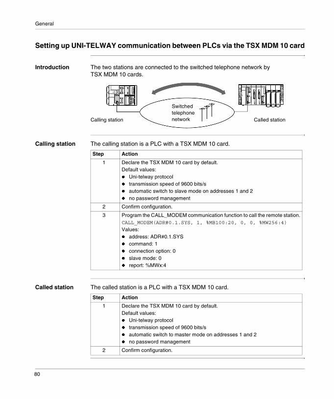
General
Setting up UNI-TELWAY communication between PLCs via the TSX MDM 10 card
Introduction The two stations are connected to the switched telephone network by TSX MDM 10 cards.
Calling station The calling station is a PLC with a TSX MDM 10 card.
Called station The called station is a PLC with a TSX MDM 10 card.
SwitchedtelephonenetworkCalling station Called station
Step Action
1 Declare the TSX MDM 10 card by default.Default values:� Uni-telway protocol� transmission speed of 9600 bits/s� automatic switch to slave mode on addresses 1 and 2� no password management
2 Confirm configuration.
3 Program the CALL_MODEM communication function to call the remote station.CALL_MODEM(ADR#0.1.SYS, 1, %MB100:20, 0, 0, %MW256:4)
Values:� address: ADR#0.1.SYS� command: 1� connection option: 0� slave mode: 0� report: %MWx:4
Step Action
1 Declare the TSX MDM 10 card by default.Default values:� Uni-telway protocol� transmission speed of 9600 bits/s� automatic switch to master mode on addresses 1 and 2� no password management
2 Confirm configuration.
80
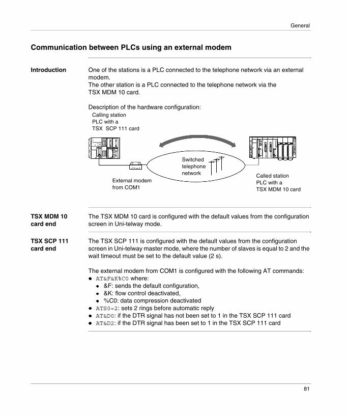
General
Communication between PLCs using an external modem
Introduction One of the stations is a PLC connected to the telephone network via an external modem.The other station is a PLC connected to the telephone network via the TSX MDM 10 card.
Description of the hardware configuration:
TSX MDM 10 card end
The TSX MDM 10 card is configured with the default values from the configuration screen in Uni-telway mode.
TSX SCP 111 card end
The TSX SCP 111 is configured with the default values from the configuration screen in Uni-telway master mode, where the number of slaves is equal to 2 and the wait timeout must be set to the default value (2 s).
The external modem from COM1 is configured with the following AT commands:� AT&F&K%C0 where:
� &F: sends the default configuration,� &K: flow control deactivated,� %C0: data compression deactivated
� ATS0=2: sets 2 rings before automatic reply� AT&D0: if the DTR signal has not been set to 1 in the TSX SCP 111 card� AT&D2: if the DTR signal has been set to 1 in the TSX SCP 111 card
Switched telephone network Called station
PLC with a TSX MDM 10 card
External modem from COM1
Calling stationPLC with a TSX SCP 111 card
81
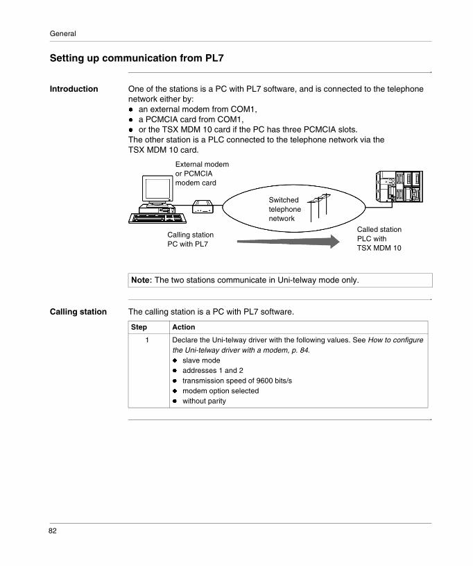
General
Setting up communication from PL7
Introduction One of the stations is a PC with PL7 software, and is connected to the telephone network either by:� an external modem from COM1,� a PCMCIA card from COM1,� or the TSX MDM 10 card if the PC has three PCMCIA slots.The other station is a PLC connected to the telephone network via the TSX MDM 10 card.
Calling station The calling station is a PC with PL7 software.
������The two stations communicate in Uni-telway mode only.
Switchedtelephonenetwork
Calling stationPC with PL7
Called stationPLC with TSX MDM 10
External modem or PCMCIA modem card
Step Action
1 Declare the Uni-telway driver with the following values. See How to configure the Uni-telway driver with a modem, p. 84.� slave mode� addresses 1 and 2� transmission speed of 9600 bits/s� modem option selected� without parity
82
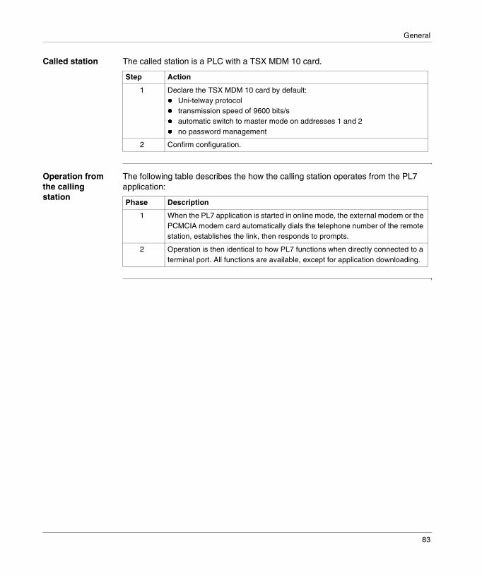
General
Called station The called station is a PLC with a TSX MDM 10 card.
Operation from the calling station
The following table describes the how the calling station operates from the PL7 application:
Step Action
1 Declare the TSX MDM 10 card by default:� Uni-telway protocol� transmission speed of 9600 bits/s� automatic switch to master mode on addresses 1 and 2� no password management
2 Confirm configuration.
Phase Description
1 When the PL7 application is started in online mode, the external modem or the PCMCIA modem card automatically dials the telephone number of the remote station, establishes the link, then responds to prompts.
2 Operation is then identical to how PL7 functions when directly connected to a terminal port. All functions are available, except for application downloading.
83

General
How to configure the Uni-telway driver with a modem
At a Glance This procedure is used to configure the Uni-telway driver on Windows 95, 98 and NT systems for communication via modem.
Procedure This procedure describes the different steps of the configuration:
Step Action
1 Click on the Drivers X-Way icon in the Windows Control Panel.
2 In the UNITELWAY DRIVER tab, click on the Configuration button
3 Select the Communications Port and click on Modify.
4 In the Modem Communication box of the Uni-Telway tab, check the Use Modem box and configure the modem connection. See How to Configure Modem Connection, p. 85.
5 Where necessary, modify the link parameters. See How to modify modem configuration parameters, p. 86.
6 Click on the OK, OK, OK buttons.
84
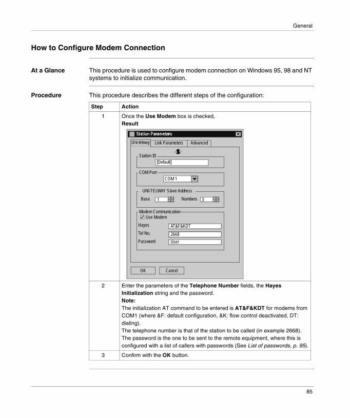
General
How to Configure Modem Connection
At a Glance This procedure is used to configure modem connection on Windows 95, 98 and NT systems to initialize communication.
Procedure This procedure describes the different steps of the configuration:
Step Action
1 Once the Use Modem box is checked,Result
2 Enter the parameters of the Telephone Number fields, the Hayes Initialization string and the password.Note:The initialization AT command to be entered is AT&F&KDT for modems from COM1 (where &F: default configuration, &K: flow control deactivated, DT: dialing).The telephone number is that of the station to be called (in example 2668).The password is the one to be sent to the remote equipment, where this is configured with a list of callers with passwords (See List of passwords, p. 95).
3 Confirm with the OK button.
Link Parameters
Station ID
COM Port
UNI-TELWAY Slave Address
Modem Communication
NumbersBase
Hayes
Tel No.
Password
AdvancedUni-telway
OK
Use Modem
Cancel
�������� ���������
[Default]
COM 1
1 3
AT&F&KDT
2668
User
85
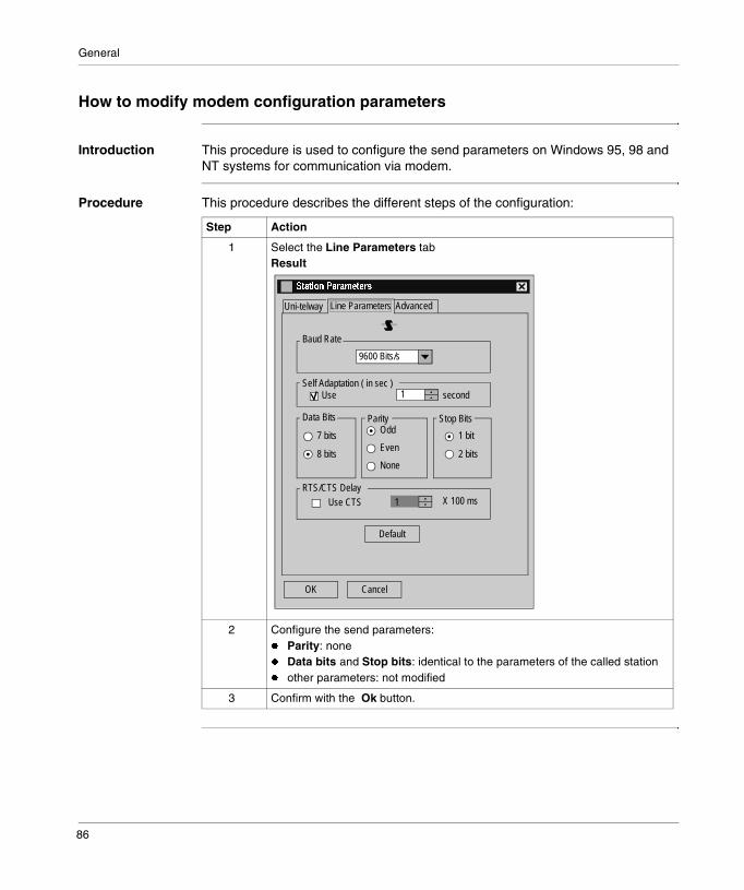
General
How to modify modem configuration parameters
Introduction This procedure is used to configure the send parameters on Windows 95, 98 and NT systems for communication via modem.
Procedure This procedure describes the different steps of the configuration:
Step Action
1 Select the Line Parameters tabResult
2 Configure the send parameters:� Parity: none� Data bits and Stop bits: identical to the parameters of the called station� other parameters: not modified
3 Confirm with the Ok button.
Line Parameters
Baud Rate
second
7 bits
AdvancedUni-telway
OK Cancel
�������� ���������
9600 Bits/s
Self Adaptation ( in sec )1Use
Use CTS RTS/CTS Delay
X 100 ms
Default
Data Bits Parity Stop Bits
8 bits
1 bit
2 bits
Odd
Even
None
1
86

7
Configuring Modem communicationIntroduction
Subject of this Chapter
This Chapter describes the Configuration process when setting up a TSX MDM 10 modem.
What’s in this Chapter?
This chapter contains the following topics:
Topic Page
How to access PCMCIA modem card parameters 88
Modem configuration screen 89
Parameters in Uni-telway mode 90
Parameters in character mode 92
Modem parameters 94
Modem parameters for a called station 95
Modem parameters for a calling station 96
87

Modem configuration
How to access PCMCIA modem card parameters
Introduction This operation describes how to access configuration parameters for the modem link via PCMCIA cards.
How to access the link
The following table shows the procedure for accessing the modem link:
Step Action
1 Access the communication channel configuration screen.
2 Select the communication channel from the drop-down menu CHANNEL 1Example
3 Select the PCMCIA card from the drop-down menu TSX MDM 10 PCMCIA MODEM CARDExample
CHANNEL 1 CHANNEL 1:
(No PCMCIA submodule)
(Link not configured) MASTCHANNEL 0CHANNEL 1
CHANNEL 1 CHANNEL 1
(No PCMCIA submodule)
(Link not configured) MASTTSX FPP 20 PCMCIA FIPWAY CARDTSX FPP 200 PCMCIA FIPWAY CARDTSX FPP 10 PCMCIA FIPIO CARDTSX MBP 100 PCMCIA MODBUS+ CARDTSX MDM 10 PCMCIA MODEM CARDFCS SCP 111 PCMCIA CARD RS232 OPENFCS SCP 114 PCMCIA CARD RS485 OPEN
88
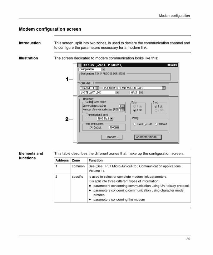
Modem configuration
Modem configuration screen
Introduction This screen, split into two zones, is used to declare the communication channel and to configure the parameters necessary for a modem link.
Illustration The screen dedicated to modem communication looks like this:
Elements and functions
This table describes the different zones that make up the configuration screen:
�������������������� ����������
Configuration
Designation: TSX P PROCESSOR 57352
CHANNEL 1 TSX MDM 10 PCMIA MODEM CARD
CHANNEL 1:
UNI TELWAY LINK MAST
�
�
Configuration
Transmission Speed
Wait timeout (ms)
Data
Parity
7 bits
Default 1000
8 bits 2 bits1 bit
Even Odd Without
9600 Bits/s
1
Calling slave modeServer address (AD0)
2Number of server addresses (AD0)
Stop Unitelway
Character mode …Modem ...
Address Zone Function
1 common See (See : PL7 Micro/Junior/Pro ; Communication applications ; Volume 1).
2 specific is used to select or complete modem link parameters.It is split into three different types of information:� parameters concerning communication using Uni-telway protocol,� parameters concerning communication using character mode
protocol� parameters concerning the modem
89
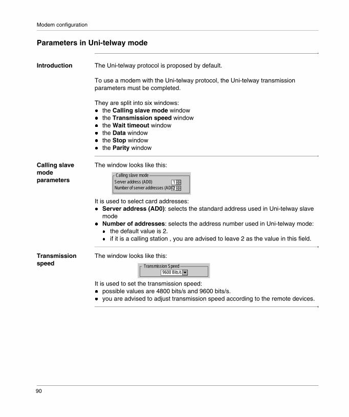
Modem configuration
Parameters in Uni-telway mode
Introduction The Uni-telway protocol is proposed by default.
To use a modem with the Uni-telway protocol, the Uni-telway transmission parameters must be completed.
They are split into six windows:� the Calling slave mode window� the Transmission speed window� the Wait timeout window� the Data window� the Stop window� the Parity window
Calling slave mode parameters
The window looks like this:
It is used to select card addresses:� Server address (AD0): selects the standard address used in Uni-telway slave
mode� Number of addresses: selects the address number used in Uni-telway mode:
� the default value is 2.� if it is a calling station , you are advised to leave 2 as the value in this field.
Transmission speed
The window looks like this:
It is used to set the transmission speed: � possible values are 4800 bits/s and 9600 bits/s.� you are advised to adjust transmission speed according to the remote devices.
1
Calling slave modeServer address (AD0)
2Number of server addresses (AD0)
Transmission Speed9600 Bits/s
90

Modem configuration
Wait timeout The window looks like this:
Wait timeout is the maximum waiting time for a link acknowledgment message from a remote device (not to be confused with the application response to READ_VAR, for example):� possible values are 30 ms and 30 s.� the default value is 1 s.� you are advised to adjust the transmission time to the transmission speed, and to
increase the timeout over long distances (e.g. inter-continental links) or in the event of a poor quality telephone link.
Data The field cannot be modified. The Uni-telway protocol imposes use of 8 data bits per character.
Stop You are advised to adjust this field according to the remote device. Generally the Uni-telway protocol imposes use of 1 data bit per character.
Parity The window looks like this:
This field is used to define the addition or non-addition of a parity bit, and its type.� Possible values are Even, Odd, or none.� The default value is odd. Generally, parity is odd� You are advised to adjust this field according to the remote device. Generally,
parity is odd for Uni-telway protocol.
Wait timeout (ms)Default 1000
������This field becomes unmodifiable if parity is odd or even.
Parity
Even Odd Without
91

Modem configuration
Parameters in character mode
Introduction Parameters in character mode are used to configure the character mode protocol if the PL7 application uses this type of communication.
Illustration The configuration screen appears when Character mode is selected:
Transmission speed
It is used to set the transmission speed: � the default speed is 9600 bits/s.� possible values are 4800 bits/s and 9600 bits/s.� you are advised to adjust transmission speed according to the remote devices.
Data The Data field is used to enter the number of data bits for coding a character:� characters are coded on 7 or 8 bits.� the default value is 8 bits.� you are advised to adjust the number of data bits according to the remote
devices.
Stop The Stop field is used to set the number of stop bits employed for detecting the end of a frame:� possible values are 1 or 2 bits.� the default value is 1 bit.� you are advised to adjust the number of stop bits according to the remote devices.
Parity This field is used to define the addition or non-addition of a parity bit, and its type.� Possible values are Even, Odd, or none.� The default value is odd.� You are advised to adjust the parity according to the remote devices.
������ �!�������
Transmission Speed
Data
ParityCharacter included
Stop
7 bits8 bits
Even Odd Without
9600 Bits/s
131 bit2 bits
Stop
Stop on reception
CR LF
OK Cancel
92
Modem configuration
Stop on reception
The following parameters are used to define the end of message character(s):� Stop (cannot be modified): is used to activate stop on reception by an end
character,� CR: is used to detect the end of a message by a carriage return,� LF: is used to detect the end of a message by a line feed,� an entry field: is used to identify an end character which is different from a CR or
LF character, using a decimal value.The possible values are:� 0 to 255 if the data is coded onto 8 bits,� 0 to 127 if the data is coded onto 7 bits,
� Character included (cannot be modified): is used to include the character at the end of the reception table for the PL7 PLC application.
93
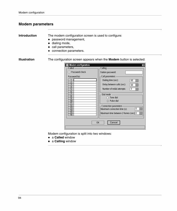
Modem configuration
Modem parameters
Introduction The modem configuration screen is used to configure:� password management,� dialing mode,� call parameters,� connection parameters.
Illustration The configuration screen appears when the Modem button is selected:
Modem configuration is split into two windows:� a Called window� a Calling window
OK Cancel
Call parameters
60
"�#���$�� �!�������
Connection parameters
Calling Called
Delay between calls (sec):
Tone dialPulse dial
Maximum connection time (s):
Password list:
Password check
1234
678910
5 Number of redial attempts:
60
3
0
0
Dialing time (sec):
11121314
1615
Station password:
Dial mode
Maximum time between 2 frames (sec):
94

Modem configuration
Modem parameters for a called station
Introduction They are split into two parts:� a Verify password field� a Password list
Verifying the password
If the box is checked, password management by the called station is enabled.By default, password testing is disabled.
List of passwords
If password management is used, each called station has a list of a maximum of 8 or 16 passwords which can be used to identify 8 or 16 separate devices (only authorizes connection for these 8 or 16 devices).The size of a word must not exceed 8 characters max. (characters = upper and lower case letters, numbers or special characters).
95
Modem configuration
Modem parameters for a calling station
Introduction They are split into two parts:� a Station password field� a Call parameters window� a Dial mode window� a Connection parameters window
Station password
Each station has its own password. It is used to identify the station. During a connection request, the calling station sends its password so that the called station can identify it and then authorize the connection.For communication with other devices, the exchange protocol, described in exchange coding (See Coding of exchanges, p. 105), must be supported by the remote device.
Call parameters These include all the parameters necessary in order to make a call:� Dialing time (60 seconds by default): corresponds to the duration of a call in
seconds.� Delay between calls (60 seconds by default): corresponds to the calling station
waiting time, in seconds, between two connection attempts. If a connection attempt fails, the PLC attempts another call after the waiting time if the number of redials has not been exceeded.
� Number of redial attempts (3 redial attempts by default): is used to set the number of call attempts in the event of failed connection attempts. If the last call fails, the CALL_MODEM function, which launched the connection attempts, sends back an error report. If the number of redial attempts configured is 0, no redial attempts will be made.
Dial mode The dial modes are:� either tone dial,� or dialing.
96
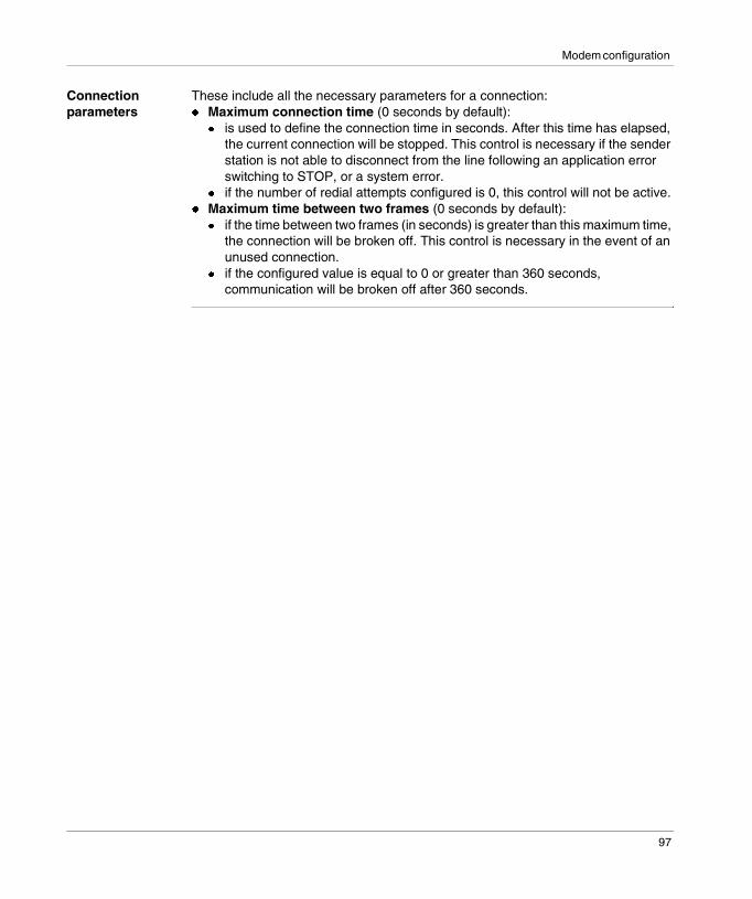
Modem configuration
Connection parameters
These include all the necessary parameters for a connection:� Maximum connection time (0 seconds by default):
� is used to define the connection time in seconds. After this time has elapsed, the current connection will be stopped. This control is necessary if the sender station is not able to disconnect from the line following an application error switching to STOP, or a system error.
� if the number of redial attempts configured is 0, this control will not be active.� Maximum time between two frames (0 seconds by default):
� if the time between two frames (in seconds) is greater than this maximum time, the connection will be broken off. This control is necessary in the event of an unused connection.
� if the configured value is equal to 0 or greater than 360 seconds, communication will be broken off after 360 seconds.
97

Modem configuration
98
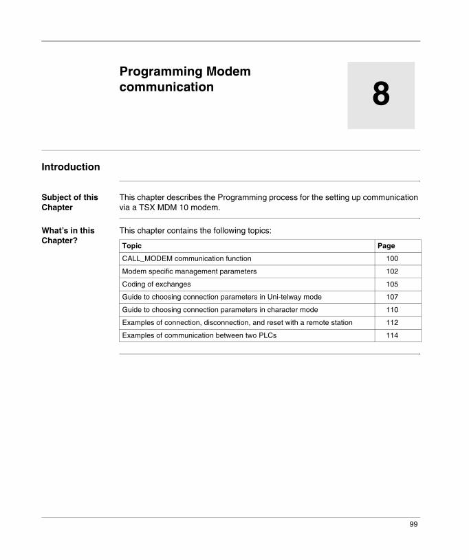
8
Programming Modem communicationIntroduction
Subject of this Chapter
This chapter describes the Programming process for the setting up communication via a TSX MDM 10 modem.
What’s in this Chapter?
This chapter contains the following topics:
Topic Page
CALL_MODEM communication function 100
Modem specific management parameters 102
Coding of exchanges 105
Guide to choosing connection parameters in Uni-telway mode 107
Guide to choosing connection parameters in character mode 110
Examples of connection, disconnection, and reset with a remote station 112
Examples of communication between two PLCs 114
99
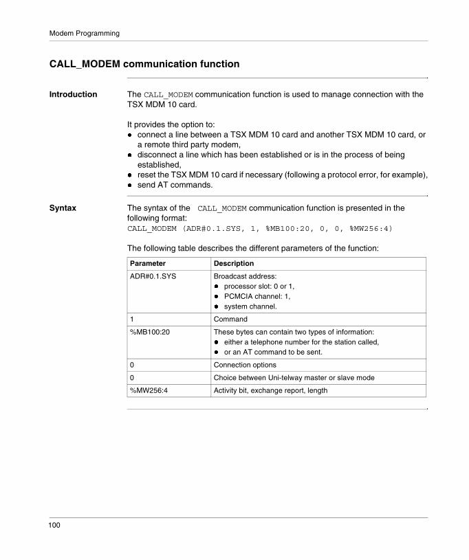
Modem Programming
CALL_MODEM communication function
Introduction The CALL_MODEM communication function is used to manage connection with the TSX MDM 10 card.
It provides the option to:� connect a line between a TSX MDM 10 card and another TSX MDM 10 card, or
a remote third party modem,� disconnect a line which has been established or is in the process of being
established,� reset the TSX MDM 10 card if necessary (following a protocol error, for example),� send AT commands.
Syntax The syntax of the CALL_MODEM communication function is presented in the following format:CALL_MODEM (ADR#0.1.SYS, 1, %MB100:20, 0, 0, %MW256:4)
The following table describes the different parameters of the function:
Parameter Description
ADR#0.1.SYS Broadcast address:� processor slot: 0 or 1,� PCMCIA channel: 1,� system channel.
1 Command
%MB100:20 These bytes can contain two types of information:� either a telephone number for the station called,� or an AT command to be sent.
0 Connection options
0 Choice between Uni-telway master or slave mode
%MW256:4 Activity bit, exchange report, length
100
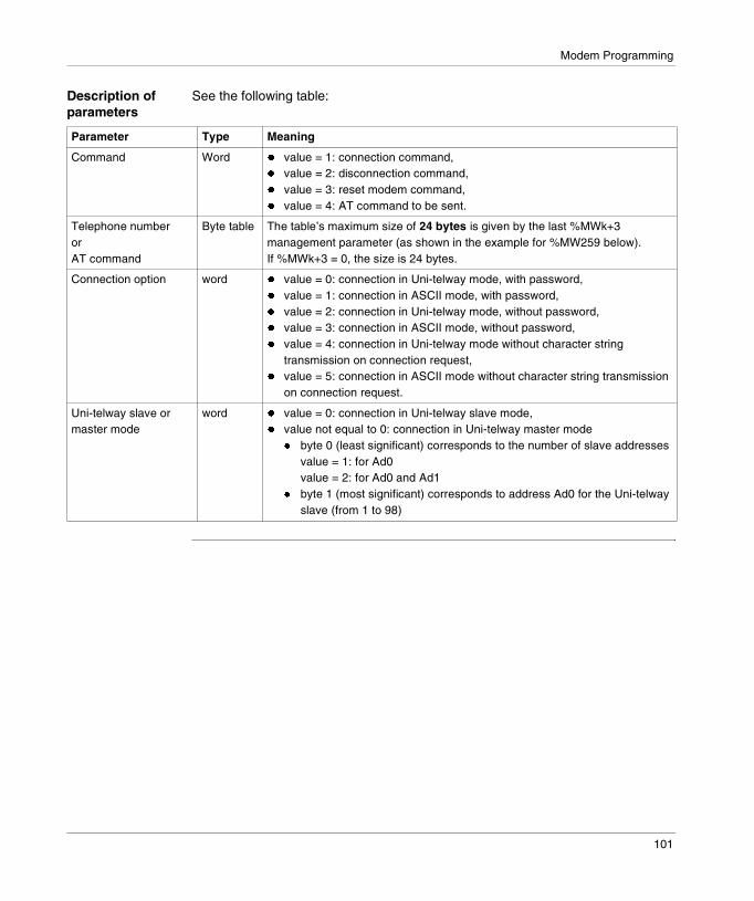
Modem Programming
Description of parameters
See the following table:
Parameter Type Meaning
Command Word � value = 1: connection command,� value = 2: disconnection command,� value = 3: reset modem command,� value = 4: AT command to be sent.
Telephone numberorAT command
Byte table The table’s maximum size of 24 bytes is given by the last %MWk+3 management parameter (as shown in the example for %MW259 below). If %MWk+3 = 0, the size is 24 bytes.
Connection option word � value = 0: connection in Uni-telway mode, with password,� value = 1: connection in ASCII mode, with password,� value = 2: connection in Uni-telway mode, without password,� value = 3: connection in ASCII mode, without password,� value = 4: connection in Uni-telway mode without character string
transmission on connection request,� value = 5: connection in ASCII mode without character string transmission
on connection request.
Uni-telway slave or master mode
word � value = 0: connection in Uni-telway slave mode,� value not equal to 0: connection in Uni-telway master mode
� byte 0 (least significant) corresponds to the number of slave addressesvalue = 1: for Ad0value = 2: for Ad0 and Ad1
� byte 1 (most significant) corresponds to address Ad0 for the Uni-telway slave (from 1 to 98)
101
Modem Programming
Modem specific management parameters
Introduction A detailed description of these parameters is available in the common section. See (PL7 Micro/Junior/Pro ; Communication applications ; Volume 1).
This document only describes parameters specific to communication via a modem.These parameters are:� Timeout,� operation report.
CALL_MODEM function timeout
Timeout of the function is a time used to check for the absence of response to the CALL_MODEM function.
This time, (increment of a 100 ms time base), is a combination of different parameters configured via the Modem Configuration screen.
It is advisable to allocate the following minimum value to this parameter:
Minimum timeout = the number of redial attempts * dialing time + (number of redial attempts - 1) * delay between redial attempts
Operation report Operation reports are specific to the modem and only significant if the communication report has the following values:� 16#00,� 16#FF.
102

Modem Programming
Communication report = 16#00
In this case, the exchange is correct.In this case, the operation report (most significant byte) is:
Value Meaning
16#00 Command executed
16#01 Non processed request
16#02 Incorrect response
16#03 Connection in progress by a remote modem
16#04 Connection in progress by a local CALL_MODEM function
16#05 Connection in progress by an external CALL_MODEM function
16#06 Connection request by a local CALL_MODEM function
16#07 Connection request by an external CALL_MODEM function
16#09 Remote station busy
16#0A Disconnection by a remote modem
16#0B Disconnection due to protocol error
16#0C Disconnection by timeout
103

Modem Programming
Communication report = 16#FF
In this case, the message is refused.In this case, the operation report (most significant byte) is:
Value Meaning
16#01 Lack of resources on connection to processor
16#02 Lack of line resources
16#03 Device missing on line
16#04 Line error
16#05 Length error
16#06 Communication channel faulty
16#07 Addressing error
16#08 Application fault
16#0B No system resources
16#0C Inactive communication function
16#0D Destination missing
16#0F Intra-station routing problem or non configured channel
16#11 Address format not handled
16#12 Lack of destination resource
16#14 Non operational connection
16#15 Absence of resource on the local channel
16#16 Non-authorized access
16#17 Incompatible network configuration
104
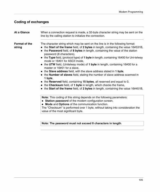
Modem Programming
Coding of exchanges
At a Glance When a connection request is made, a 32-byte character string may be sent on the line by the calling station to initialize the connection.
Format of the string
The character string which may be sent on the line is in the following format:� the Start of the frame field, of 2 bytes in length, containing the value 16#531B,� the Password field, of 8 bytes in length, containing the value of the station
password (8 characters),� the Type field, (protocol type) of 1 byte in length, containing 16#00 for Uni-telway
mode or 16#01 for ASCII mode,� the UTW field, (Unitelway mode) of 1 byte in length, containing 16#00 for a
master or 16#01 for a slave,� the Slave address field, with the slave address stated in 1 byte,� the Number of slaves field, stating the number of slave address scanned in
1 byte,� the Reserved field, containing 15 bytes, all reserved and equal to 0,� the Checksum field, of 1 byte in length, which checks the frame,� the Start of the frame field, of 2 bytes in length, containing the value 16#451B,
������This coding of this string depends on the following parameters:� �������#������� of the modem configuration screen,� +��� and �#����� of the communication function.The "Checksum" is performed over 1 byte, without taking into consideration the value of the most significant byte.
�������"��#��������%��������,�����-��"������������ ��!�".
105
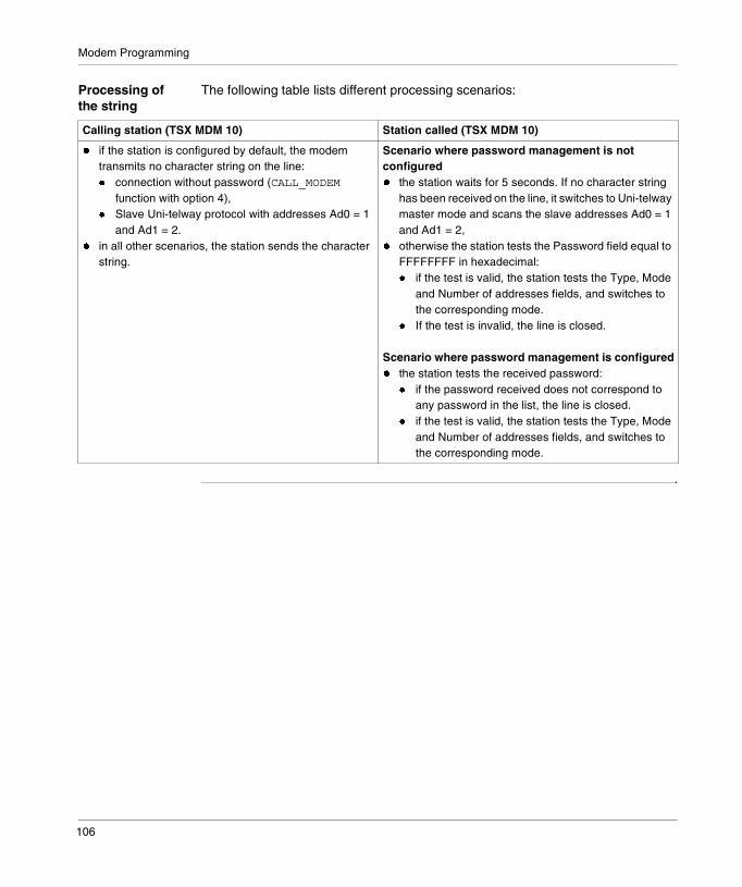
Modem Programming
Processing of the string
The following table lists different processing scenarios:
Calling station (TSX MDM 10) Station called (TSX MDM 10)
� if the station is configured by default, the modem transmits no character string on the line:� connection without password (CALL_MODEM
function with option 4),� Slave Uni-telway protocol with addresses Ad0 = 1
and Ad1 = 2.� in all other scenarios, the station sends the character
string.
Scenario where password management is not configured� the station waits for 5 seconds. If no character string
has been received on the line, it switches to Uni-telway master mode and scans the slave addresses Ad0 = 1 and Ad1 = 2,
� otherwise the station tests the Password field equal to FFFFFFFF in hexadecimal:� if the test is valid, the station tests the Type, Mode
and Number of addresses fields, and switches to the corresponding mode.
� If the test is invalid, the line is closed.
Scenario where password management is configured� the station tests the received password:
� if the password received does not correspond to any password in the list, the line is closed.
� if the test is valid, the station tests the Type, Mode and Number of addresses fields, and switches to the corresponding mode.
106
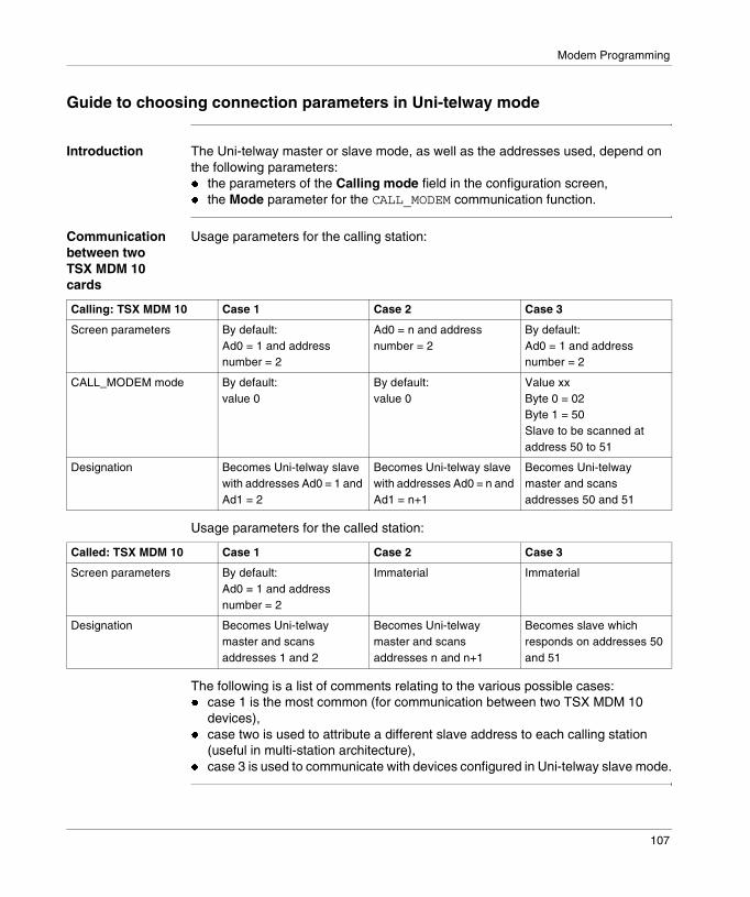
Modem Programming
Guide to choosing connection parameters in Uni-telway mode
Introduction The Uni-telway master or slave mode, as well as the addresses used, depend on the following parameters:� the parameters of the Calling mode field in the configuration screen,� the Mode parameter for the CALL_MODEM communication function.
Communication between two TSX MDM 10 cards
Usage parameters for the calling station:
Usage parameters for the called station:
The following is a list of comments relating to the various possible cases:� case 1 is the most common (for communication between two TSX MDM 10
devices),� case two is used to attribute a different slave address to each calling station
(useful in multi-station architecture),� case 3 is used to communicate with devices configured in Uni-telway slave mode.
Calling: TSX MDM 10 Case 1 Case 2 Case 3
Screen parameters By default:Ad0 = 1 and address number = 2
Ad0 = n and address number = 2
By default:Ad0 = 1 and address number = 2
CALL_MODEM mode By default:value 0
By default:value 0
Value xxByte 0 = 02Byte 1 = 50Slave to be scanned at address 50 to 51
Designation Becomes Uni-telway slave with addresses Ad0 = 1 and Ad1 = 2
Becomes Uni-telway slave with addresses Ad0 = n and Ad1 = n+1
Becomes Uni-telway master and scans addresses 50 and 51
Called: TSX MDM 10 Case 1 Case 2 Case 3
Screen parameters By default:Ad0 = 1 and address number = 2
Immaterial Immaterial
Designation Becomes Uni-telway master and scans addresses 1 and 2
Becomes Uni-telway master and scans addresses n and n+1
Becomes slave which responds on addresses 50 and 51
107

Modem Programming
Communication with a third party device
Usage parameters for the calling station (TSX MDM 10 card):
Usage parameters for the called station (third party device):
The following is a list of comments relating to the various possible cases:� case 1 is not significant,� for case 2, the initialization protocol must be implemented (exchange coding),� for case 3, the initialization protocol must be implemented (exchange coding).
Calling: TSX MDM 10 Case 1 Case 2 Case 3
Screen parameters By default:Ad0 = 1 and address number = 2
Ad0 = n and address number = 2
By default:Ad0 = 1 and address number = 2
CALL_MODEM mode By default:value 0
By default:value 0
Value xxByte 0 = 02Byte 1 = 50Slave to be scanned at address 50 to 51
Designation Becomes Uni-telway slave with addresses Ad0 = 1 and Ad1 = 2
Becomes Uni-telway slave with addresses Ad0 = n and Ad1 = n+1
Becomes Uni-telway master and scans addresses 50 and 51
Called: third party device Case 1 Case 2 Case 3
Designation Becomes Uni-telway master and scans addresses 1 and 2
Becomes Uni-telway master and scans addresses n and n+1
Becomes slave which responds on addresses 50 and 51
108

Modem Programming
Communication from a third party device
Usage parameters for the calling station (third party device):
Usage parameters for the called station (TSX MDM 10 card):
The following is a list of comments relating to the various possible cases:� cases 1 and 2 are not significant,� for case 3, the initialization protocol must be implemented (exchange coding).
Calling: third party device Case 1 Case 2 Case 3
Designation Becomes slave which responds on addresses 1 and 2
Becomes slave which responds on addresses n and n+1
Becomes a Uni-telway master and scans addresses configured on the TSX MDM 10 card
Called: TSX MDM 10 Case 1 Case 2 Case 3
Screen parameters By default:Ad0 = 1 and address number = 2
Requires the configuration Ad0 = n and address number = 2
Immaterial
Designation Becomes Uni-telway master and scans addresses Ad0 = 1 and Ad1 = 2
Becomes Uni-telway master and scans addresses Ad0 = n and Ad1 = n+1
Becomes a Uni-telway slave with the configured addresses
109

Modem Programming
Guide to choosing connection parameters in character mode
Introduction The character mode depends on the following parameters:� the configuration screen parameters,� the Option parameter for the CALL_MODEM communication function.
Communication between two TSX MDM 10 cards
Usage parameters for the calling station:
Usage parameters for the called station:
Communication with a third party device
Usage parameters for the calling station (TSX MDM 10 card):
Usage parameters for the called station (third party device):
Calling: TSX MDM 10
Screen parameters Configuration in character mode (data coded on 8 bits)
CALL_MODEM option Character mode protocol
Called: TSX MDM 10
Screen parameters Configuration in character mode is identical to that of calling station
������In this configuration, the character string, described in the exchange coding, is transmitted on the line.
Calling: TSX MDM 10
Screen parameters Configuration in character mode (data coded on 8 bits)
CALL_MODEM option Character mode protocol
Called: third party device
Screen parameters Implementation of initialization protocol (exchange coding)
������In this configuration, the character string, described in the exchange coding, is transmitted on the line.
110

Modem Programming
Communication from a third party device
Usage parameters for the calling station (third party device):
Usage parameters for the called station (TSX MDM 10 card):
Calling: third party device
Screen parameters Configuration in character mode (data coded on 8 bits)
Designation Implementation of initialization protocol (exchange coding) for sending the character string
Called: TSX MDM 10
Screen parameters Configuration in character mode is identical to that of calling station
������In this configuration, the character string, described in the exchange coding, is transmitted on the line.
111

Modem Programming
Examples of connection, disconnection, and reset with a remote station
Introduction The following examples are to assist with installation of the various CALL_MODEM services.
Example 1 Connection in Uni-telway slave mode, without password:CALL_MODEM(ADR#0.1.SYS, 1, %MB100:20, 2, 0, %MW256:4)
The following table describes the different parameters of the function:
Example 2 Connection in Uni-telway slave mode, with password:CALL_MODEM(ADR#0.1.SYS, 1, %MB100:20, 0, 0, %MW256:4)
The following table describes the different parameters of the function:
Parameter Description
ADR#0.1.SYS Modem address
1 Connection
%MB100:20 Telephone number of called station
2 Uni-telway mode, without password
0 Uni-telway slave mode
%MW256:4 Activity bit, exchange report, length
Parameter Description
ADR#0.1.SYS Modem address
1 Connection
%MB100:20 Telephone number of called station
0 Uni-telway mode, with password
0 Uni-telway slave mode
%MW256:4 Activity bit, exchange report, length
112
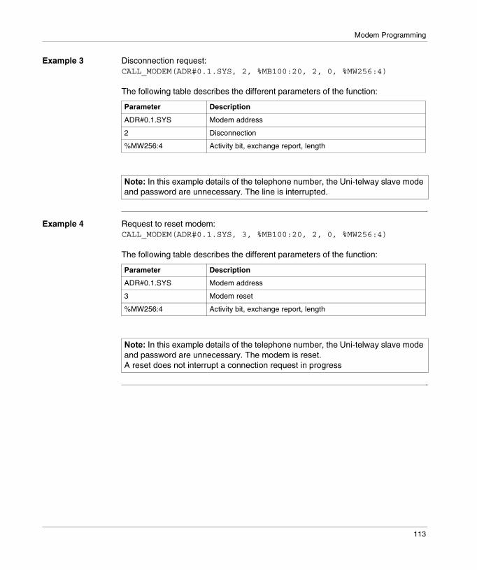
Modem Programming
Example 3 Disconnection request:CALL_MODEM(ADR#0.1.SYS, 2, %MB100:20, 2, 0, %MW256:4)
The following table describes the different parameters of the function:
Example 4 Request to reset modem:CALL_MODEM(ADR#0.1.SYS, 3, %MB100:20, 2, 0, %MW256:4)
The following table describes the different parameters of the function:
Parameter Description
ADR#0.1.SYS Modem address
2 Disconnection
%MW256:4 Activity bit, exchange report, length
������In this example details of the telephone number, the Uni-telway slave mode and password are unnecessary. The line is interrupted.
Parameter Description
ADR#0.1.SYS Modem address
3 Modem reset
%MW256:4 Activity bit, exchange report, length
������In this example details of the telephone number, the Uni-telway slave mode and password are unnecessary. The modem is reset.A reset does not interrupt a connection request in progress
113

Modem Programming
Examples of communication between two PLCs
Introduction The following example describes the different phases of a communication between two Micro PLCs linked by the telephone network:� the connection phase,� the data exchange phase,� the disconnection phase.
Connection phase
The calling station makes the call in Uni-telway slave mode without password management:
CALL_MODEM(ADR#0.1.SYS, 1, %MB50:4, 2, 0, %MW1024:4)
The following table describes the different parameters of the function:
Parameter Variable Description
Address ADR#0.1.SYS Modem addressProcessor slot: 0 or 1PCMCIA channel: 1System server: SYS
Command 1 Connection command
Telephone number %MB50:4 Telephone number of called station (in bytes)
Option 2 Connection in Uni-telway mode, without password
Mode 0 Connection in Uni-telway slave mode
Report %MW1024:4 %MW1026 = 300, corresponds to a 30 second time-out.%MW 1027 = 4, corresponds to the length in bytes of the telephone number to call (4 bytes in the example).
114
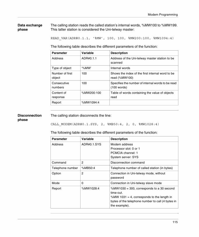
Modem Programming
Data exchange phase
The calling station reads the called station’s internal words, %MW100 to %MW199. This latter station is considered the Uni-telway master:
READ_VAR(ADR#0.1.1, ‘%MW’, 100, 100, %MW200:100, %MW1094:4)
The following table describes the different parameters of the function:
Disconnection phase
The calling station disconnects the line:
CALL_MODEM(ADR#0.1.SYS, 2, %MB50:4, 2, 0, %MW1028:4)
The following table describes the different parameters of the function:
Parameter Variable Description
Address ADR#0.1.1 Address of the Uni-telway master station to be scanned
Type of object ‘%MW’ Internal words
Number of first object
100 Shows the index of the first internal word to be read (%MW100)
Consecutive numbers
100 Specifies the number of internal words to be read (100 words)
Content of response
%MW200:100 Table of words containing the value of objects read
Report %MW1094:4
Parameter Variable Description
Address ADR#0.1.SYS Modem addressProcessor slot: 0 or 1PCMCIA channel: 1System server: SYS
Command 2 Disconnection command
Telephone number %MB50:4 Telephone number of called station (in bytes)
Option 2 Connection in Uni-telway mode, without password
Mode 0 Connection in Uni-telway slave mode
Report %MW1028:4 %MW1030 = 300, corresponds to a 30 second time-out.%MW 1031 = 4, corresponds to the length in bytes of the telephone number to call (4 bytes in the example).
115

Modem Programming
116
9
Debugging Modem communicationIntroduction
Subject of this Chapter
This Chapter describes the Debugging process when setting up a TSX MDM 10 modem.
What’s in this Chapter?
This chapter contains the following topics:
Topic Page
Modem debugging screen 118
Debugging parameters 119
117
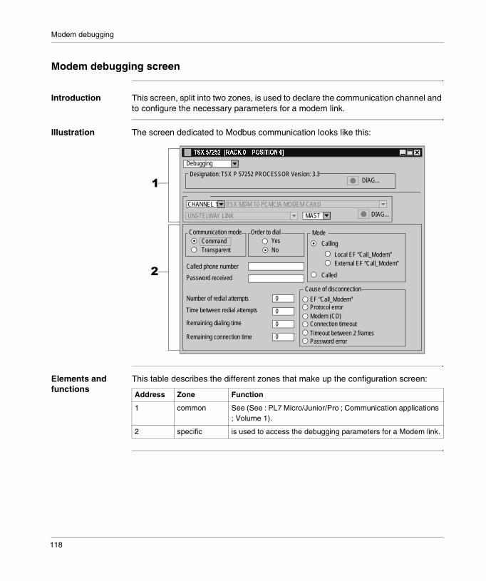
Modem debugging
Modem debugging screen
Introduction This screen, split into two zones, is used to declare the communication channel and to configure the necessary parameters for a modem link.
Illustration The screen dedicated to Modbus communication looks like this:
Elements and functions
This table describes the different zones that make up the configuration screen:
�
�
CHANNEL 1
�������������������� ����������
Designation: TSX P 57252 PROCESSOR Version: 3.3
TSX MDM 10 PCMCIA MODEM CARD
UNI-TELWAY LINK MAST
Debugging
DIAG...
DIAG...
0
0
0
0
Cause of disconnection
ModeOrder to dial Communication mode
Called phone number
Password received
Number of redial attempts
Time between redial attempts
Remaining dialing time
Remaining connection time
EF “Call_Modem”Protocol errorModem (CD)Connection timeoutTimeout between 2 framesPassword error
Called
Local EF “Call_Modem”
CallingYesNoTransparent
Command
External EF “Call_Modem”
Address Zone Function
1 common See (See : PL7 Micro/Junior/Pro ; Communication applications ; Volume 1).
2 specific is used to access the debugging parameters for a Modem link.
118

Modem debugging
Debugging parameters
Introduction The specific part is split into several windows:� the Communication mode window,� the Order to dial window,� the Mode window,� the Cause of disconnection window,� a field grouping.
Communication mode
This is used to identify the state of connection:� command: connection request in progress (connection being established),� transparent: connection established.
Order to dial This indicates if a CALL_MODEM communication function has been received by the TSX MDM 10 card and is being processed.
Mode This is used to specify the connection mode:� calling: the station initiated the call. The screen shows whether the CALL_MODEM
communication function has been sent by the local station or by a remote station via a network,
� called: the station is the call receiver.
Cause of disconnection
This indicates the causes of a line disconnection:� EF CALL_MODEM: the local station has initiated the disconnection using the
CALL_MODEM function,� protocol error: a protocol error is the cause of the disconnection,� modem (CD): the remote modem has initiated the disconnection,� connection timeout: the duration of the connection has overrun,� timeout between 2 frames: the delay between 2 frames has overrun,� password error: the password received is invalid - it does not appear in the local
station list.
Additional fields They provide the following information:� number of redial attempts: indicates the number of redial attempts remaining,� time between redial attempts: indicates the time remaining between redial
attempts,� remaining dialing time: indicates the remaining dialing time,� remaining connection time: indicates the remaining connection time (if the local
station is connected).
119

Modem debugging
120
10
Language objects associated with Modem communicationIntroduction
Subject of this Section
This Chapter introduces language objects associated with communication via a TSX MDM 10 modem.
What’s in this Chapter?
This chapter contains the following topics:
Topic Page
Language objects in implicit exchange 122
Language objects for explicit exchange 123
Explicit exchange management and reports 127
Language objects associated with configuration 128
121

Modem language objects
Language objects in implicit exchange
Introduction This page describes all the language objects for implicit exchange in modem communication that can be displayed or modified by the application program. (PL7 Micro/Junior/Pro ; Communication applications ; Volume 1)
Bit objects The table below shows the different bit objects for implicit exchange.
Word objects The table below shows the different word objects for implicit exchange.
Object (1) Function Meaning
%Ixy.MOD.ERR Module error bit This bit set to 1, indicates a module error (at least one of the channels is faulty,…)
%Ixy.i.ERR Channel error bit This bit set at 1 indicates a faulty channel.
Key
(1) Address xy.i� x: corresponds to the rack number,� y: corresponds to the module number,� i: corresponds to the channel number.
Object (1) Function Meaning
%IWxy.i.0 Not used -
%IWxy.i.1 General status of slaves
x0 = 1: if at least one slave does not respond
Key
(1) Address xy.i� x: corresponds to the rack number,� y: corresponds to the module number,� i: corresponds to the channel number.
122

Modem language objects
Language objects for explicit exchange
Introduction This page describes all the language objects for explicit exchange in Modem communication that can be displayed or modified by the application program. (PL7 Micro/Junior/Pro ; Communication applications ; Volume 1)
Word objects The table below shows the different word objects for explicit exchange.
Object (1) Function Meaning
%MWxy.MOD.2 Module status � x0 = 1: defective module,� x1 = 1: functional error (error between the
processor and the module, adjustment or configuration error, …),
� x2 = 1: terminal block fault (not connected),� x3 = 1: self-tests running,� x4 = 1: reserved,� x5 = 1: error in hardware or software
configuration (the module present is not that declared in the configuration, the sub-modules are not compatible),
� x6 = 1: missing module,� x7 = 1: error in one of the sub-modules.
%MWxy.i.2 Standard channel status
� x0 = 1: single station on the network,� x1 = 1: not used,� x2 = 1: transmission line error,� x3 = 1: not used,� x4 = 1: internal software fault,� x5 = 1: error in hard- or software configuration,
or configuration missing,� x6 = 1: communication error with the
processor,� x7 = 1: application fault (double address
station).
%MWxy.i.3 Specific channel status
0 for Uni-telway master mode1 for Uni-telway slave mode
%MWxy.i.4to%MWxy.i.7
Not used -
%MWxy.i.8 Slave address Standard address of calling slave
123
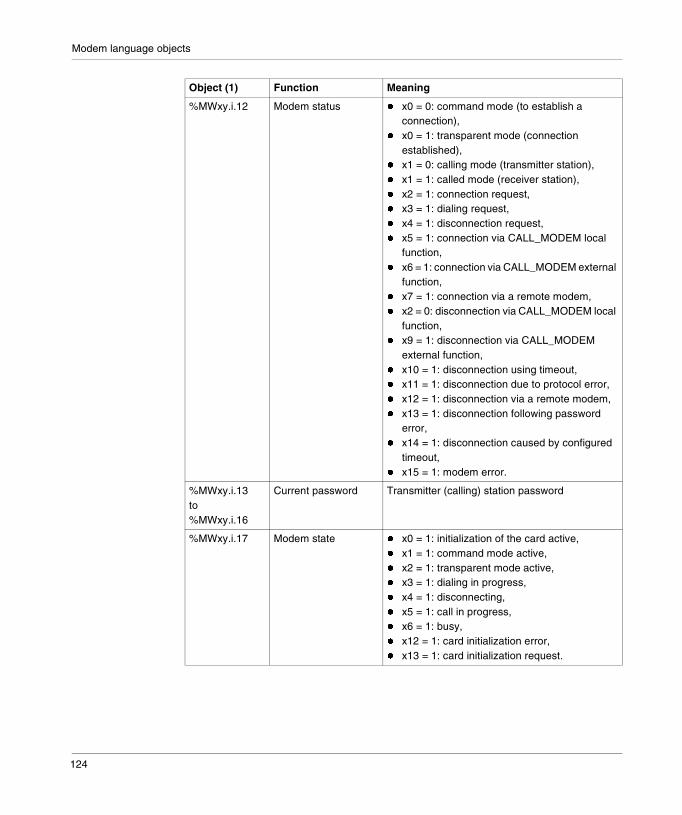
Modem language objects
%MWxy.i.12 Modem status � x0 = 0: command mode (to establish a connection),
� x0 = 1: transparent mode (connection established),
� x1 = 0: calling mode (transmitter station),� x1 = 1: called mode (receiver station),� x2 = 1: connection request,� x3 = 1: dialing request,� x4 = 1: disconnection request,� x5 = 1: connection via CALL_MODEM local
function,� x6 = 1: connection via CALL_MODEM external
function,� x7 = 1: connection via a remote modem,� x2 = 0: disconnection via CALL_MODEM local
function,� x9 = 1: disconnection via CALL_MODEM
external function,� x10 = 1: disconnection using timeout,� x11 = 1: disconnection due to protocol error,� x12 = 1: disconnection via a remote modem,� x13 = 1: disconnection following password
error,� x14 = 1: disconnection caused by configured
timeout,� x15 = 1: modem error.
%MWxy.i.13to%MWxy.i.16
Current password Transmitter (calling) station password
%MWxy.i.17 Modem state � x0 = 1: initialization of the card active,� x1 = 1: command mode active,� x2 = 1: transparent mode active,� x3 = 1: dialing in progress,� x4 = 1: disconnecting,� x5 = 1: call in progress,� x6 = 1: busy,� x12 = 1: card initialization error,� x13 = 1: card initialization request.
Object (1) Function Meaning
124

Modem language objects
%MWxy.i.18 Dialing state � x0 = 1: dialing in progress,� x1 = 1: AT D command transmission (dialing),� x2 = 1: connection received,� x3 = 1: password test running,� x4 = 1: valid password received,� x5 = 1: protocol mode can be activated,� x6 :not used,� x7 = 1:Carriage Return not detected,� x8 = 1: DCD signal missing,� x9 = 1: dialing time overrun,� x10 = 1: general input/output error,� x11 = 1: illegal command,� x12 = 1: disconnection while dialing.
%MWxy.i.19 State of called unit � x0 = 1: call in progress,� x1 = 1: AT A command transmission (answer),� x2 = 1: connection received,� x3 = 1: password test running,� x4 = 1: password received,� x5 = 1: password not received,� x6 = 1: Carriage Return not detected,� x10 = 1: general input/output error,� x11 = 1: illegal command.
%MWxy.i.20 Connection state � x0 = 1: DTR signal active,� x1 = 1: AT H command transmission
(hang up),� x2 = 1: awaiting disconnection.
%MWxy.i.21to%MWxy.i.32
Telephone number Telephone number of called station
%MWxy.i.33 Remaining number of redial attempts
Remaining number of calls to be made
%MWxy.i.34 Delay between remaining calls
Remaining delay value between calls is between 0 and 255 (between 30 s and 180 s)
%MWxy.i.35 Remaining dialing time
Remaining dialing time value is between 40 and 255 seconds
%MWxy.i.36 Remaining time between 2 messages
Remaining time value between two frames
%MWxy.i.37 Remaining connection time
Display of remaining connection time
%MWxy.i.38 Input character trace Offset of last character received, between 0 and 99 bytes
Object (1) Function Meaning
125
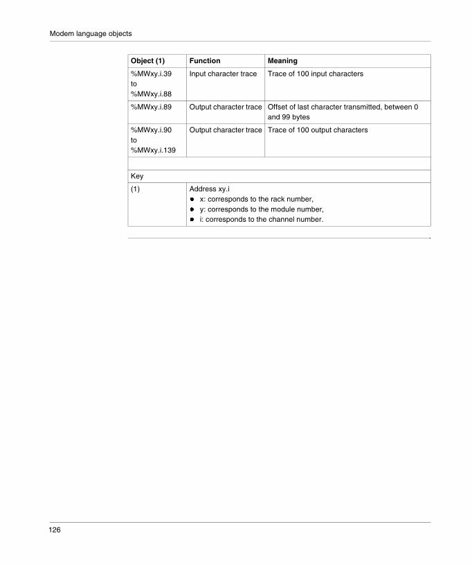
Modem language objects
%MWxy.i.39to%MWxy.i.88
Input character trace Trace of 100 input characters
%MWxy.i.89 Output character trace Offset of last character transmitted, between 0 and 99 bytes
%MWxy.i.90to%MWxy.i.139
Output character trace Trace of 100 output characters
Key
(1) Address xy.i� x: corresponds to the rack number,� y: corresponds to the module number,� i: corresponds to the channel number.
Object (1) Function Meaning
126

Modem language objects
Explicit exchange management and reports
Introduction This page describes all the language objects that manage explicit exchanges. (See : PL7 Micro/Junior/Pro ; Communication applications ; Volume 1)
Word objects The table below shows the different word objects for the management of explicit exchanges.
Object (1) Function Meaning
%MWxy.MOD.0 Module exchanges in progress
� x0 = 1: reading status in progress� x1 = 1: sending of command parameters to the
communication module� x2 = 1: sending of adjustment parameters to the
communication module
%MWxy.MOD.1 Module report � x1 = 0: command parameters received and accepted by the module
� x2 = 0: adjustment parameters received and accepted by the module
%MWxy.i.0 Channel exchanges in progress
� x0 = 1: reading status in progress� x1 = 1: sending of command parameters to the
communication channel� x2 = 1: sending of adjustment parameters to the
communication channel
%MWxy.i.1 Channel report � x1 = 0: command parameters received and accepted by the communication channel
� x2 = 0: adjustment parameters received and accepted by the communication channel
Key
(1) Address xy.i� x: corresponds to the rack number� y: corresponds to the module number� i: corresponds to the channel number
127

Modem language objects
Language objects associated with configuration
Introduction This page describes all the configuration language objects for Modem communication that can be displayed by the application program.
Internal constants
The following table describes the internal constants:
Object Function Meaning
%KWxy.i.0 Type 0 for Uni-telway mode
%KWxy.i.1 Speed / format Byte 0 = speed� 16#00 = 1200 bits/s, ..., 16#03 = 9600 bits/sByte 1: format� x8: bit number (1 = 8 bits, 0 = 7 bits)� x9 = 1: parity management� x10: Parity type (1 = odd, 0 = even)� x11: stop bit (1 = 1 bit, 0 = 2 bits)
%KWxy.i.2 Timeout Value of timeout
%KWxy.i.3 Slave address Byte 0: standard slave addressByte 1: number of consecutive addresses (from 1 to 3)
%KWxy.i.4 Not used
%KWxy.i.5 RTS/CTS delay Value of delay in hundredths of a millisecond
%KWxy.i.6 Speed / Format in ASCII mode
Byte 0 = speed in ASCII mode� 16#00 = 1200 bits/s, ...,16#03 = 9600 bits/sByte 1: format in ASCII mode� x8: bit number (1 = 8 bits, 0 = 7 bits)� x9 = 1: parity management� x10: Parity type (1 = odd, 0 = even)� x11: stop bit (1 = 1 bit, 0 = 2 bits)
%KWxy.i.7 Stop Bits received Byte 0� x0 = 1: end character enabled� x1 = 1: end character includedByte 1: value of frame end character
%KWxy.i.8 Not used
%KWxy.i.9 Number of redial attempts
Value between 0 and 10 redial attempts
%KWxy.i.10 Delay between redial attempts
Byte 0: delay between redial attempts in seconds, value between 30 and 180 seconds in increments of 30 s
128

Modem language objects
Micro internal constants
The following table describes internal constants for Micro PLCs:
Premium internal constants
The following table describes internal constants for Premium PLCs:
%KWxy.i.11 Dial mode Byte 0: type of dialing� x0 = 0: tone dial� x0 = 1: pulse dial� x1 = 0: password test� x1 = 1: no password testByte 1: dialing time value between 30 and 180 seconds in increments of 30 s
%KWxy.i.12 Maximum time between 2 messages
Message transfer check, value in seconds between 0 and 32767 seconds
%KWxy.i.13 Maximum connection time
Value between 0 and 32767 seconds� = 0: no connection time control� > 0: connection time control
%KWxy.i.14 to 17
Passwords 148 byte string
Object Function Meaning
Object Function Meaning
%KWxy.i.18 to 49
List of passwords List of 8 passwords, with a maximum of 8 characters per password
%KWxy.i.50 to 123
Modem string 148 byte string
Object Function Meaning
%KWxy.i.18 to 81
List of passwords List of 16 passwords, with a maximum of 8 characters per password
%KWxy.i.82 to 155
Modem string 148 byte string
129

Modem language objects
130
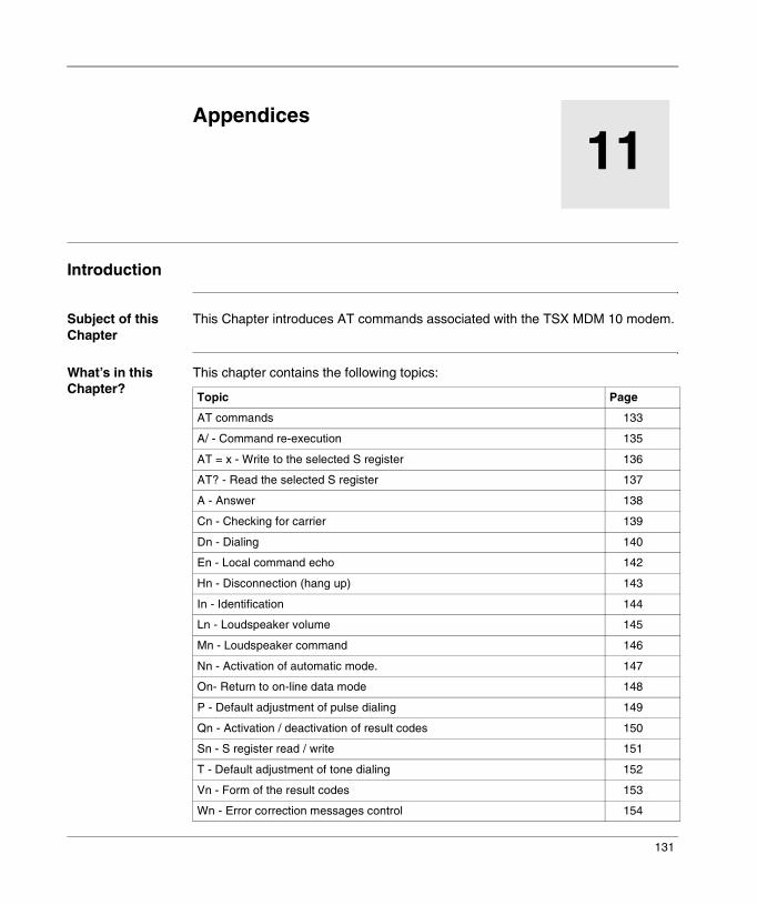
11
AppendicesIntroduction
Subject of this Chapter
This Chapter introduces AT commands associated with the TSX MDM 10 modem.
What’s in this Chapter?
This chapter contains the following topics:
Topic Page
AT commands 133
A/ - Command re-execution 135
AT = x - Write to the selected S register 136
AT? - Read the selected S register 137
A - Answer 138
Cn - Checking for carrier 139
Dn - Dialing 140
En - Local command echo 142
Hn - Disconnection (hang up) 143
In - Identification 144
Ln - Loudspeaker volume 145
Mn - Loudspeaker command 146
Nn - Activation of automatic mode. 147
On- Return to on-line data mode 148
P - Default adjustment of pulse dialing 149
Qn - Activation / deactivation of result codes 150
Sn - S register read / write 151
T - Default adjustment of tone dialing 152
Vn - Form of the result codes 153
Wn - Error correction messages control 154
131
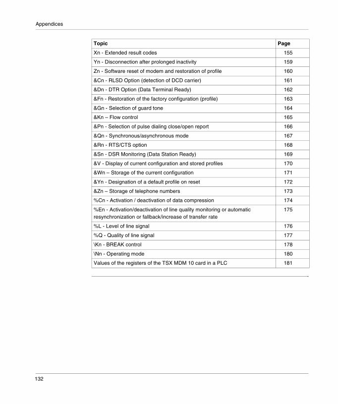
Appendices
Xn - Extended result codes 155
Yn - Disconnection after prolonged inactivity 159
Zn - Software reset of modem and restoration of profile 160
&Cn - RLSD Option (detection of DCD carrier) 161
&Dn - DTR Option (Data Terminal Ready) 162
&Fn - Restoration of the factory configuration (profile) 163
&Gn - Selection of guard tone 164
&Kn – Flow control 165
&Pn - Selection of pulse dialing close/open report 166
&Qn - Synchronous/asynchronous mode 167
&Rn - RTS/CTS option 168
&Sn - DSR Monitoring (Data Station Ready) 169
&V - Display of current configuration and stored profiles 170
&Wn – Storage of the current configuration 171
&Yn - Designation of a default profile on reset 172
&Zn – Storage of telephone numbers 173
%Cn - Activation / deactivation of data compression 174
%En - Activation/deactivation of line quality monitoring or automatic resynchronization or fallback/increase of transfer rate
175
%L - Level of line signal 176
%Q - Quality of line signal 177
\Kn - BREAK control 178
\Nn - Operating mode 180
Values of the registers of the TSX MDM 10 card in a PLC 181
Topic Page
132
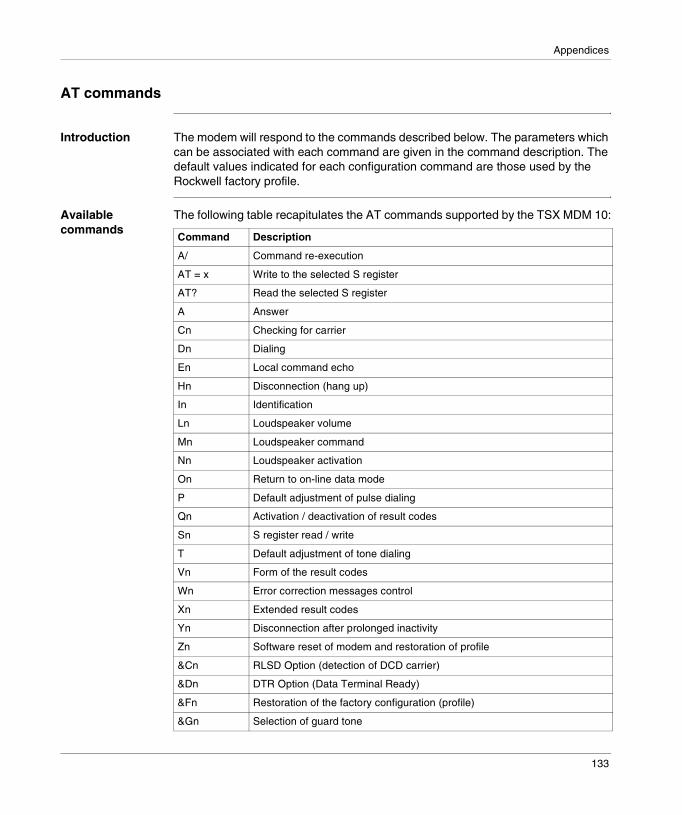
Appendices
AT commands
Introduction The modem will respond to the commands described below. The parameters which can be associated with each command are given in the command description. The default values indicated for each configuration command are those used by the Rockwell factory profile.
Available commands
The following table recapitulates the AT commands supported by the TSX MDM 10:
Command Description
A/ Command re-execution
AT = x Write to the selected S register
AT? Read the selected S register
A Answer
Cn Checking for carrier
Dn Dialing
En Local command echo
Hn Disconnection (hang up)
In Identification
Ln Loudspeaker volume
Mn Loudspeaker command
Nn Loudspeaker activation
On Return to on-line data mode
P Default adjustment of pulse dialing
Qn Activation / deactivation of result codes
Sn S register read / write
T Default adjustment of tone dialing
Vn Form of the result codes
Wn Error correction messages control
Xn Extended result codes
Yn Disconnection after prolonged inactivity
Zn Software reset of modem and restoration of profile
&Cn RLSD Option (detection of DCD carrier)
&Dn DTR Option (Data Terminal Ready)
&Fn Restoration of the factory configuration (profile)
&Gn Selection of guard tone
133
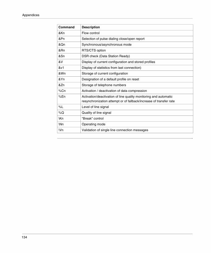
Appendices
&Kn Flow control
&Pn Selection of pulse dialing close/open report
&Qn Synchronous/asynchronous mode
&Rn RTS/CTS option
&Sn DSR check (Data Station Ready)
&V Display of current configuration and stored profiles
&v1 Display of statistics from last connection)
&Wn Storage of current configuration
&Yn Designation of a default profile on reset
&Zn Storage of telephone numbers
%Cn Activation / deactivation of data compression
%En Activation/deactivation of line quality monitoring and automatic resynchronization attempt or of fallback/increase of transfer rate
%L Level of line signal
%Q Quality of line signal
\Kn "Break" control
\Nn Operating mode
\Vn Validation of single line connection messages
Command Description
134

Appendices
A/ - Command re-execution
Introduction The modem behaves as though the last command line had been returned by the DTE. "A/" repeats all the commands contained in the command buffer.The principal use of this command is to be able to renew a call (using the dial command) which has not finished following an engaged signal or no reply. This command must appear alone on the command line and must finish with the character "/". It must not finish with a carriage return.
135
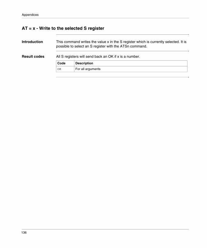
Appendices
AT = x - Write to the selected S register
Introduction This command writes the value x in the S register which is currently selected. It is possible to select an S register with the ATSn command.
Result codes All S registers will send back an OK if x is a number.
Code Description
OK For all arguments
136

Appendices
AT? - Read the selected S register
Introduction This command reads and displays the selected S register. It is possible to select an S register with the ATSn command.
Result codes All S registers will send back an OK if x is a number.
Code Description
OK For all arguments
137

Appendices
A - Answer
Introduction The modem connects and attempts to answer the call received if all the necessary conditions have been fulfilled. Once contact has been made, the modem connects in answer mode.
138

Appendices
Cn - Checking for carrier
Introduction This command is included solely for reasons of compatibility; its only effect is to return a result code. The only valid parameter is 1.
Result codes The following table lists the possible command responses.
Code Description
OK n = 1
ERROR If n is not equal to 1
139
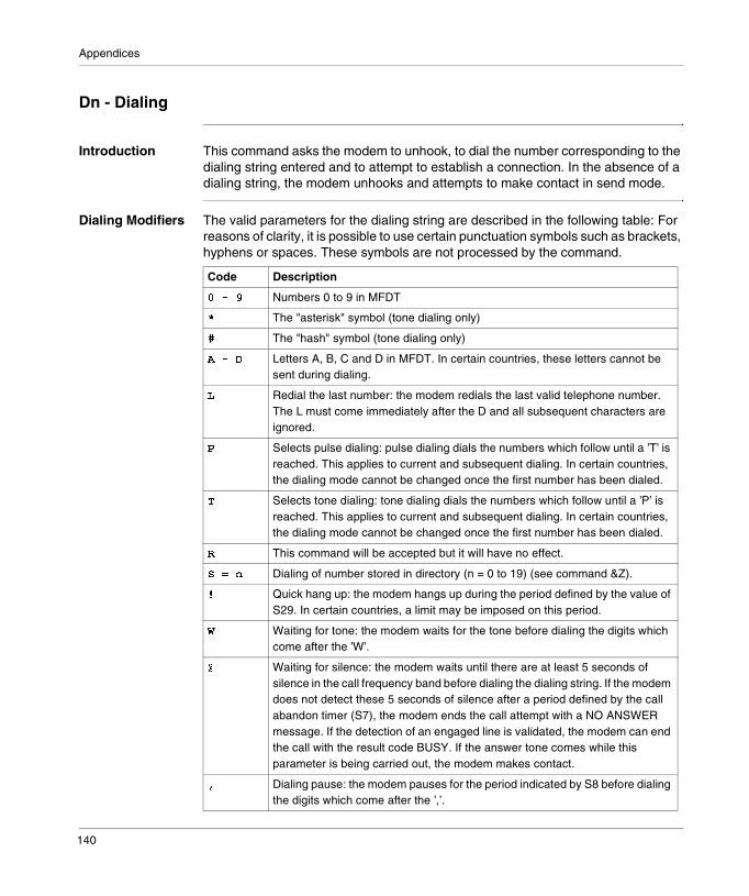
Appendices
Dn - Dialing
Introduction This command asks the modem to unhook, to dial the number corresponding to the dialing string entered and to attempt to establish a connection. In the absence of a dialing string, the modem unhooks and attempts to make contact in send mode.
Dialing Modifiers The valid parameters for the dialing string are described in the following table: For reasons of clarity, it is possible to use certain punctuation symbols such as brackets, hyphens or spaces. These symbols are not processed by the command.
Code Description
����� Numbers 0 to 9 in MFDT
� The "asterisk" symbol (tone dialing only)
� The "hash" symbol (tone dialing only)
����� Letters A, B, C and D in MFDT. In certain countries, these letters cannot be sent during dialing.
� Redial the last number: the modem redials the last valid telephone number. The L must come immediately after the D and all subsequent characters are ignored.
Selects pulse dialing: pulse dialing dials the numbers which follow until a ’T’ is reached. This applies to current and subsequent dialing. In certain countries, the dialing mode cannot be changed once the first number has been dialed.
Selects tone dialing: tone dialing dials the numbers which follow until a ’P’ is reached. This applies to current and subsequent dialing. In certain countries, the dialing mode cannot be changed once the first number has been dialed.
� This command will be accepted but it will have no effect.
�� �� Dialing of number stored in directory (n = 0 to 19) (see command &Z).
� Quick hang up: the modem hangs up during the period defined by the value of S29. In certain countries, a limit may be imposed on this period.
� Waiting for tone: the modem waits for the tone before dialing the digits which come after the ’W’.
� Waiting for silence: the modem waits until there are at least 5 seconds of silence in the call frequency band before dialing the dialing string. If the modem does not detect these 5 seconds of silence after a period defined by the call abandon timer (S7), the modem ends the call attempt with a NO ANSWER message. If the detection of an engaged line is validated, the modem can end the call with the result code BUSY. If the answer tone comes while this parameter is being carried out, the modem makes contact.
� Dialing pause: the modem pauses for the period indicated by S8 before dialing the digits which come after the ’,’.
140
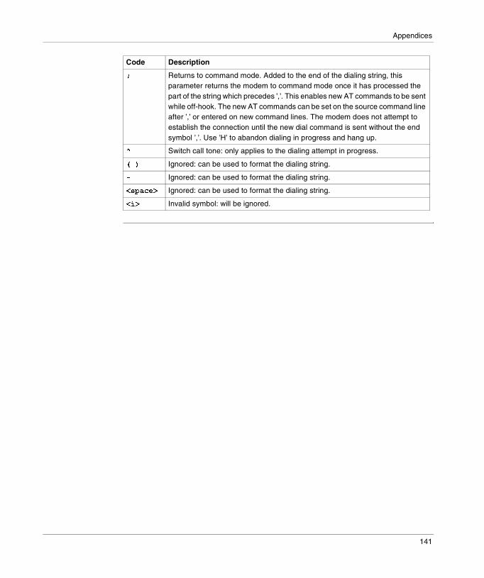
Appendices
� Returns to command mode. Added to the end of the dialing string, this parameter returns the modem to command mode once it has processed the part of the string which precedes ’,’. This enables new AT commands to be sent while off-hook. The new AT commands can be set on the source command line after ’,’ or entered on new command lines. The modem does not attempt to establish the connection until the new dial command is sent without the end symbol ’,’. Use ’H’ to abandon dialing in progress and hang up.
� Switch call tone: only applies to the dialing attempt in progress.
��� Ignored: can be used to format the dialing string.
� Ignored: can be used to format the dialing string.
������� Ignored: can be used to format the dialing string.
��� Invalid symbol: will be ignored.
Code Description
141

Appendices
En - Local command echo
Introduction According to the parameter indicated, the modem activates or deactivates the appearance of the characters on the DTE. The parameter value, if valid, is written in the S14 bit.
Parameters The parameters are.
Result codes The following table lists the possible command responses.
Code Description
�� Deactivates command echo.
� Activates command echo (default value)
Code Description
OK n = 0 or 1.
ERROR If n is not equal to 0 or 1.
142

Appendices
Hn - Disconnection (hang up)
Introduction This command launches a hanging up sequence; it is possible that it is not available in certain countries.
Parameters The parameters are:
Result codes The following table lists the possible command responses.
Code Description
!� The modem frees the line if it is currently connected, and ends all attempts (AT&T) in progress. Any processing which is particular to a country, to the modulation or to the error correction protocol (S38) is carried out outside the H0 command.
! Only in STN mode; if the modem is on-hook, it unhooks and goes into command mode. The modem hangs up at the end of the time period defined by S7.
Code Description
OK n = 0 or 1.
ERROR If n is not equal to 0 or 1.
143

Appendices
In - Identification
Introduction The modem reports the result corresponding to the entered command parameter to the DTE.
Parameters The parameters are:
Result codes The following table lists the possible command responses.
Code Description
"� Gives the product code (e.g. ’14400’).
" Gives the pre-calculated checksum of the read-only memory ROM (e.g. ’007’).
"# Gives the firmware revision level (e.g. ’V1.000S’).
"$ Gives the identification string defined by the OEM (e.g. ’RC96ACL’).
"% Gives the country code (e.g. ’022’).
"& Gives the model of the modem data pumping device.
Code Description
OK n = 0 to 6.
ERROR If n is not in the range 0 to 6.
144

Appendices
Ln - Loudspeaker volume
Introduction The modem adjusts the loudspeaker volume control according to the parameter entered. The parameter value, if valid, is written in bits 0 and 1 of S22.
Parameters The parameters are:
Result codes The following table lists the possible command responses.
Code Description
�� Low or deactivated volume.
� Low volume (default value).
�' Medium volume.
�# High volume.
Code Description
OK n = 0 to 3.
ERROR If n is not in the range 0 to 3.
145
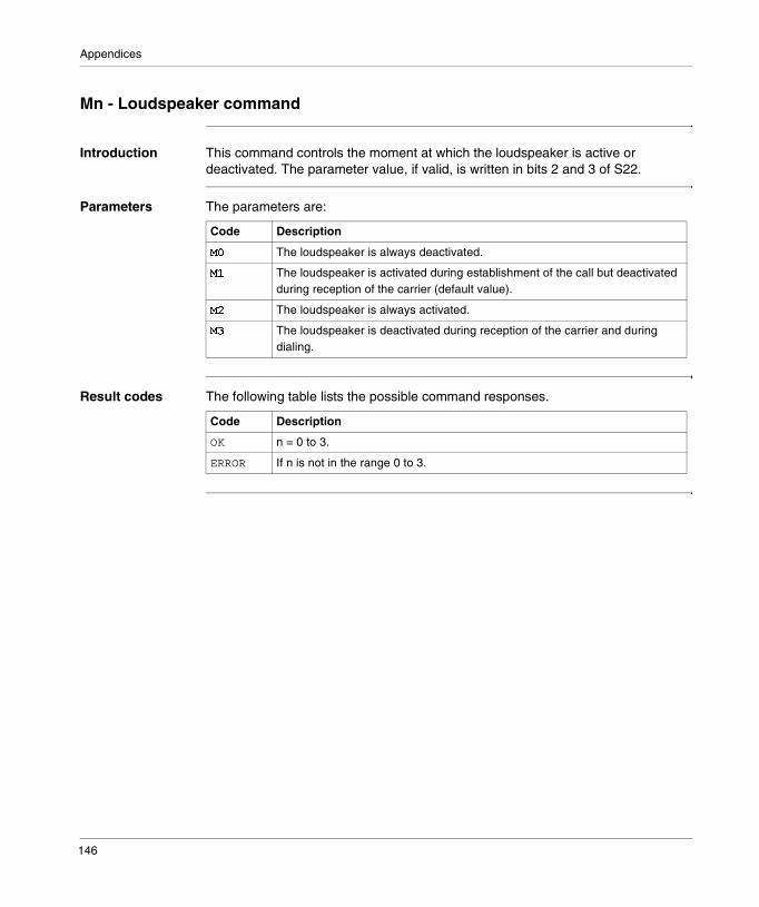
Appendices
Mn - Loudspeaker command
Introduction This command controls the moment at which the loudspeaker is active or deactivated. The parameter value, if valid, is written in bits 2 and 3 of S22.
Parameters The parameters are:
Result codes The following table lists the possible command responses.
Code Description
(� The loudspeaker is always deactivated.
( The loudspeaker is activated during establishment of the call but deactivated during reception of the carrier (default value).
(' The loudspeaker is always activated.
(# The loudspeaker is deactivated during reception of the carrier and during dialing.
Code Description
OK n = 0 to 3.
ERROR If n is not in the range 0 to 3.
146

Appendices
Nn - Activation of automatic mode.
Introduction This command activates or deactivates detection of automatic mode. The parameter value, if valid, is written in bit 1 of S31.
Parameters The parameters are:
Result codes The following table lists the possible command responses.
Observations 1. The Nn and S37=x commands have priority over the values of the +MS command. When the N0 or N1 command is sent, the sub-parameters of +MS are updated to reflect the values of Nn and S37 (see descriptions of the +MS command and of the S37 register).For example:� N1S37=10 updates the sub-parameters of the +MS command as follows:
+MS=10,1,300,12000� N037=10 updates the sub-parameters of the +MS command as follows:
+MS=10,0,12000,120002. It is recommended to use the +MS command rather than the Nn and S37=x
commands. The Nn and S37=x commands are supported to ensure compatibility with the existing communication software.
Code Description
)� Detection of automatic mode is deactivated (equivalent to giving the 0 value to the sub-parameter +MS). The handshaking which follows is made according to the content of S37 or, if S37 is at 0, according to the most recently detected DTE baud rate.
) Detection of automatic mode is activated (equivalent to giving the value 1 to the sub-parameter +MS). The handshaking which follows is made according to the automatic mode algorithm supported by the modem, in other words according to the content of S37 or, if S37 is 0, by starting at 28800 b/s V.34 (RC288). This command also equates to F0 (RC144) (default value).
Code Description
OK n = 0 to 1.
ERROR If n is not in the range 0 to 1.
147

Appendices
On- Return to on-line data mode
Introduction This command determines the way in which the modem sets in on-line data mode. If the modem is in the on-line command mode, this command sets it in on-line data mode with or without a resynchronization attempt.If the modem is in off-line command mode (no connection), ERROR is displayed as the response.
Parameters The parameters are:
Result codes The following table lists the possible command responses.
Code Description
*� Switches to on-line data mode without resynchronization attempt. The processing is determined by the call establishment task. In general, if there is a connection, this command reconnects the DTE to the remote modem after an escape (+++).
* In STN mode only; switches to on-line data mode after a resynchronization attempt.
Code Description
CONNECT n = 0 to 3.
ERROR If n is not in the range 0 to 3.
148

Appendices
P - Default adjustment of pulse dialing
Introduction This command imposes pulse dialing until the receives the next ’T’ dialing modifier or the next ’T’ command. It sets bit 5 of S14. On execution of a dialing command which expressly indicates the dialing mode of the call in question (e.g. ATDT…), this command is canceled so that all subsequent dialing will be tone dialing (see 'T' command).In certain countries, this command may not be authorized.
Result codes The following table lists the possible command responses.
Code Description
OK -
149
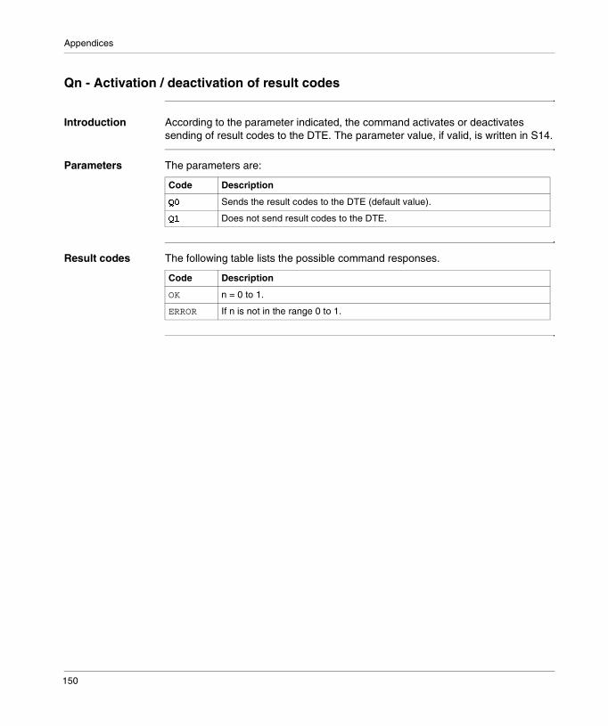
Appendices
Qn - Activation / deactivation of result codes
Introduction According to the parameter indicated, the command activates or deactivates sending of result codes to the DTE. The parameter value, if valid, is written in S14.
Parameters The parameters are:
Result codes The following table lists the possible command responses.
Code Description
+� Sends the result codes to the DTE (default value).
+ Does not send result codes to the DTE.
Code Description
OK n = 0 to 1.
ERROR If n is not in the range 0 to 1.
150
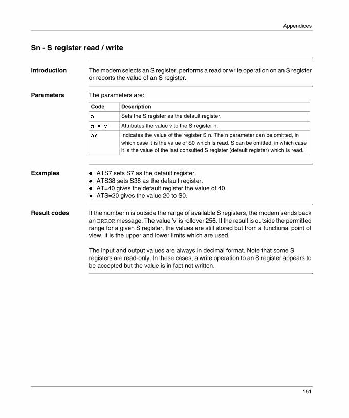
Appendices
Sn - S register read / write
Introduction The modem selects an S register, performs a read or write operation on an S register or reports the value of an S register.
Parameters The parameters are:
Examples � ATS7 sets S7 as the default register.� ATS38 sets S38 as the default register.� AT=40 gives the default register the value of 40.� ATS=20 gives the value 20 to S0.
Result codes If the number n is outside the range of available S registers, the modem sends back an ERROR message. The value ’v’ is rollover 256. If the result is outside the permitted range for a given S register, the values are still stored but from a functional point of view, it is the upper and lower limits which are used.
The input and output values are always in decimal format. Note that some S registers are read-only. In these cases, a write operation to an S register appears to be accepted but the value is in fact not written.
Code Description
� Sets the S register as the default register.
�� �, Attributes the value v to the S register n.
�- Indicates the value of the register S n. The n parameter can be omitted, in which case it is the value of S0 which is read. S can be omitted, in which case it is the value of the last consulted S register (default register) which is read.
151
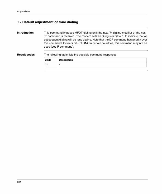
Appendices
T - Default adjustment of tone dialing
Introduction This command imposes MFDT dialing until the next ’P’ dialing modifier or the next ’P’ command is received. The modem sets an S register bit to ’1’ to indicate that all subsequent dialing will be tone dialing. Note that the DP command has priority over this command. It clears bit 5 of S14. In certain countries, this command may not be used (see P command).
Result codes The following table lists the possible command responses.
Code Description
OK -
152
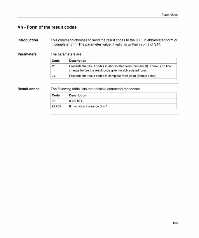
Appendices
Vn - Form of the result codes
Introduction This command chooses to send the result codes to the DTE in abbreviated form or in complete form. The parameter value, if valid, is written in bit 3 of S14.
Parameters The parameters are:
Result codes The following table lists the possible command responses.
Code Description
.� Presents the result codes in abbreviated form (numerical). There is no line change before the result code given in abbreviated form.
. Presents the result codes in complete form (text) (default value).
Code Description
OK n = 0 to 1.
ERROR If n is not in the range 0 to 1.
153
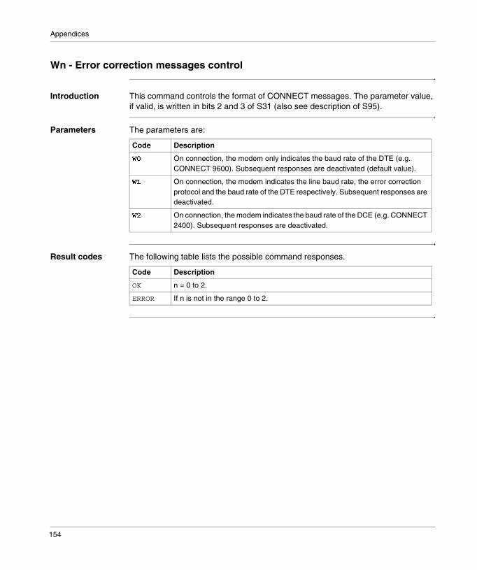
Appendices
Wn - Error correction messages control
Introduction This command controls the format of CONNECT messages. The parameter value, if valid, is written in bits 2 and 3 of S31 (also see description of S95).
Parameters The parameters are:
Result codes The following table lists the possible command responses.
Code Description
�� On connection, the modem only indicates the baud rate of the DTE (e.g. CONNECT 9600). Subsequent responses are deactivated (default value).
� On connection, the modem indicates the line baud rate, the error correction protocol and the baud rate of the DTE respectively. Subsequent responses are deactivated.
�' On connection, the modem indicates the baud rate of the DCE (e.g. CONNECT 2400). Subsequent responses are deactivated.
Code Description
OK n = 0 to 2.
ERROR If n is not in the range 0 to 2.
154

Appendices
Xn - Extended result codes
Introduction This command selects the set of messages that the modem will use to inform the DTE of the command results. The table indicates the messages which are activated for each value of X.If the modem is in fax mode (+FCLASS=1 or 2), the only message sent to indicate that a connection has been made is CONNECT without any indication of baud rate.
Parameters The parameters are:
Code Description
/� Deactivates detection of engaged tones except if this is imposed by the national requirements; only sends the result codes OK, CONNECT, RING, NO CARRIER, ERROR and NO ANSWER.The blind dialing mode is activated/deactivated by the national parameters. If detection of the engaged tone is in use and if such a tone is detected, it is the response NO CARRIER which is sent back instead of BUSY.If dial tone detection is in use or selected and if no such tone is detected, it is the response NO CARRIER which is sent back instead of NO DIAL TONE.The binary value 000 is written in bits 6, 5 and 4 of S22 respectively.
/ Deactivates detection of engaged tones except if this is imposed by the national requirments; only sends the result codes OK, CONNECT, RING, NO CARRIER, ER-ROR, NO ANSWER and CONNECT XXXX (XXXX = baud rate). Blind dialing mode is activated/deactivated by the national parameters. If detection of the engaged tone is in use and if such a tone is detected, it is the response NO CARRIER which is sent back instead of BUSY.If dial tone detection is in use or selected and if no such tone is detected, it is the response NO CARRIER which is sent back instead of NO DIAL TONE.The binary value 100 is written in bits 6, 5 and 4 of S22 respectively.
/' Deactivates detection of engaged tones except if this is imposed by national re-quirements; only sends the result codes OK, CONNECT, RING, NO CARRIER, ER-ROR, NO DIAL TONE, NO ANSWER and CONNECT XXXX.If detection of the engaged tone is in use and if such a tone is detected, it is the response NO CAR-RIER which is sent back instead of BUSY.If dial tone detection is in use or select-ed and if no such tone is detected, it is the response NO CARRIER which is sent back instead of NO DIAL TONE.The binary value 101 is written in bits 6, 5 and 4 of S22 respectively.
/# Activates detection of engaged tones; only sends the result codes OK, CONNECT, RING, NO CARRIER, ERROR, NO DIAL TONE, NO ANSWER et CONNECT XXXX.Blind dialing mode is activated/deactivated by the national parameters.If dial tone detection is in use and if no such tone is detected, it is the reply NO CARRIER which is sent instead of NO DIAL TONE.The binary value 110 is written in bits 6, 5 and 4 of S22 respectively.
/$ Activates detection of engaged tones; sends all messages. The binary value 111 is written in bits 6, 5 and 4 of S22 (default value) respectively.
155
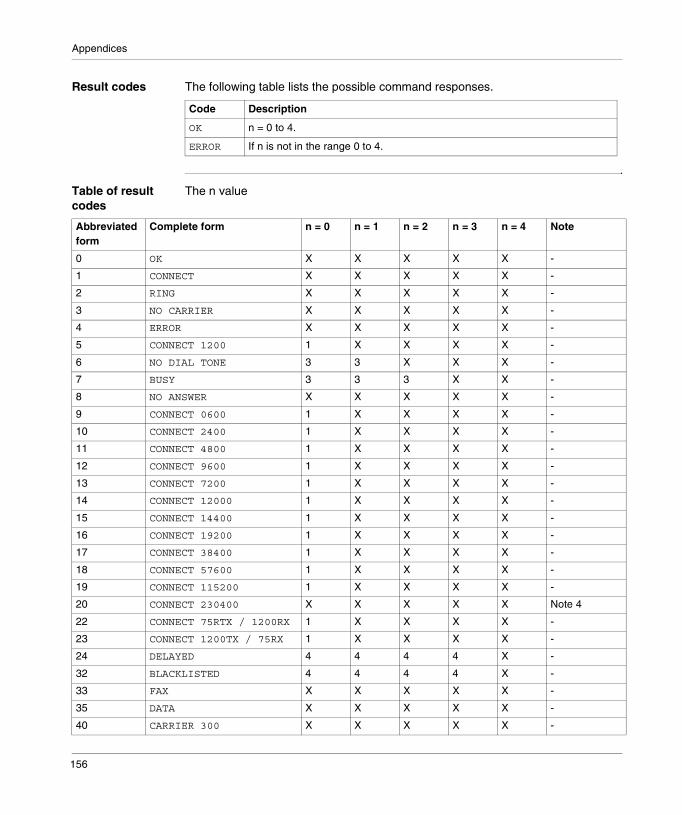
Appendices
Result codes The following table lists the possible command responses.
Table of result codes
The n value
Code Description
OK n = 0 to 4.
ERROR If n is not in the range 0 to 4.
Abbreviated form
Complete form n = 0 n = 1 n = 2 n = 3 n = 4 Note
0 OK X X X X X -
1 CONNECT X X X X X -
2 RING X X X X X -
3 NO CARRIER X X X X X -
4 ERROR X X X X X -
5 CONNECT 1200 1 X X X X -
6 NO DIAL TONE 3 3 X X X -
7 BUSY 3 3 3 X X -
8 NO ANSWER X X X X X -
9 CONNECT 0600 1 X X X X -
10 CONNECT 2400 1 X X X X -
11 CONNECT 4800 1 X X X X -
12 CONNECT 9600 1 X X X X -
13 CONNECT 7200 1 X X X X -
14 CONNECT 12000 1 X X X X -
15 CONNECT 14400 1 X X X X -
16 CONNECT 19200 1 X X X X -
17 CONNECT 38400 1 X X X X -
18 CONNECT 57600 1 X X X X -
19 CONNECT 115200 1 X X X X -
20 CONNECT 230400 X X X X X Note 4
22 CONNECT 75RTX / 1200RX 1 X X X X -
23 CONNECT 1200TX / 75RX 1 X X X X -
24 DELAYED 4 4 4 4 X -
32 BLACKLISTED 4 4 4 4 X -
33 FAX X X X X X -
35 DATA X X X X X -
40 CARRIER 300 X X X X X -
156
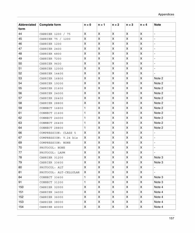
Appendices
44 CARRIER 1200 / 75 X X X X X -
45 CARRIER 75 / 1200 X X X X X -
46 CARRIER 1200 X X X X X -
47 CARRIER 2400 X X X X X -
48 CARRIER 4800 X X X X X -
49 CARRIER 7200 X X X X X -
50 CARRIER 9600 X X X X X -
51 CARRIER 12000 X X X X X -
52 CARRIER 14400 X X X X X -
53 CARRIER 16800 X X X X X Note 2
54 CARRIER 19200 X X X X X Note 2
55 CARRIER 21600 X X X X X Note 2
56 CARRIER 24000 X X X X X Note 2
57 CARRIER 26400 X X X X X Note 2
58 CARRIER 28800 X X X X X Note 2
59 CONNECT 16800 1 X X X X Note 2
61 CONNECT 21600 1 X X X X Note 2
62 CONNECT 24000 1 X X X X Note 2
63 CONNECT 26400 1 X X X X Note 2
64 CONNECT 28800 1 X X X X Note 2
66 COMPRESSION: CLASS 5 X X X X X -
67 COMPRESSION: V.24 bis X X X X X -
69 COMPRESSION: NONE X X X X X -
70 PROTOCOL: NONE X X X X X -
77 PROTOCOL: LAPM X X X X X -
78 CARRIER 31200 X X X X X Note 3
79 CARRIER 33600 X X X X X Note 3
80 PROTOCOL: ALT X X X X X -
81 PROTOCOL: ALT-CELLULAR X X X X X -
84 CONNECT 33600 1 X X X X Note 3
91 CONNECT 31200 1 X X X X Note 3
150 CARRIER 32000 X X X X X Note 4
151 CARRIER 34000 X X X X X Note 4
152 CARRIER 36000 X X X X X Note 4
153 CARRIER 38000 X X X X X Note 4
154 CARRIER 40000 X X X X X Note 4
Abbreviated form
Complete form n = 0 n = 1 n = 2 n = 3 n = 4 Note
157

Appendices
155 CARRIER 42000 X X X X X Note 4
156 CARRIER 44000 X X X X X Note 4
157 CARRIER 46000 X X X X X Note 4
158 CARRIER 48000 X X X X X Note 4
159 CARRIER 50000 X X X X X Note 4
160 CARRIER 52000 X X X X X Note 4
161 CARRIER 54000 X X X X X Note 4
162 CARRIER 56000 X X X X X Note 4
165 CONNECT 32000 X X X X X Note 4
166 CONNECT 34000 X X X X X Note 4
167 CONNECT 36000 X X X X X Note 4
168 CONNECT 38000 X X X X X Note 4
169 CONNECT 40000 X X X X X Note 4
170 CONNECT 42000 X X X X X Note 4
171 CONNECT 44000 X X X X X Note 4
172 CONNECT 46000 X X X X X Note 4
173 CONNECT 48000 X X X X X Note 4
174 CONNECT 50000 X X X X X Note 4
175 CONNECT 52000 X X X X X Note 4
176 CONNECT 54000 X X X X X Note 4
177 CONNECT 56000 X X X X X Note 4
+ F4 +FCERROR X X X X X -
Observations
1 An ‘X’ in the column means that the message in question (in its text form or only numerical) is generated when the corresponding value ‘n’ (indicated at the top of column) has been selected with the ATXn command. If the column is blank, no message is generated for this table slot. A number sends back a less explicit message (in complete or abbreviated form) which will be sent to the table slot in question.
2 RC288 modems and higher.
3 RC336 modems and higher.
4 RC56 modems.
Abbreviated form
Complete form n = 0 n = 1 n = 2 n = 3 n = 4 Note
158

Appendices
Yn - Disconnection after prolonged inactivity
Introduction This command activates/deactivates generation and response to a disconnection after prolonged inactivity. The parameter value, if valid, is written in bit 7 of S21.
Parameters The parameters are:
Result codes The following table lists the possible command responses.
Code Description
0� Deactivates disconnection after prolonged inactivity.
0 Activates disconnection after prolonged inactivity. In error correction mode, the modem sends an inactivity signal of four seconds before hanging up. In the same mode, the modem responds to the receipt of a prolonged inactivity signal (for example a ’break’ signal of more than 1.6 seconds) by hanging up.
Code Description
OK n = 0 to 1.
ERROR If n is not in the range 0 to 1.
159

Appendices
Zn - Software reset of modem and restoration of profile
Introduction The modem executes a software reset and reestablishes the configuration profile defined by the parameter.In the absence of a parameter, zero is assumed.
Parameters The parameters are:
Result codes The following table lists the possible command responses.
Code Description
1� Software reset of modem and reestablishment of stored profile 0.
1 Software reset of modem and reestablishment of stored profile 1.
Code Description
OK n = 0 to 1.
ERROR If n is not in the range 0 to 1.
160
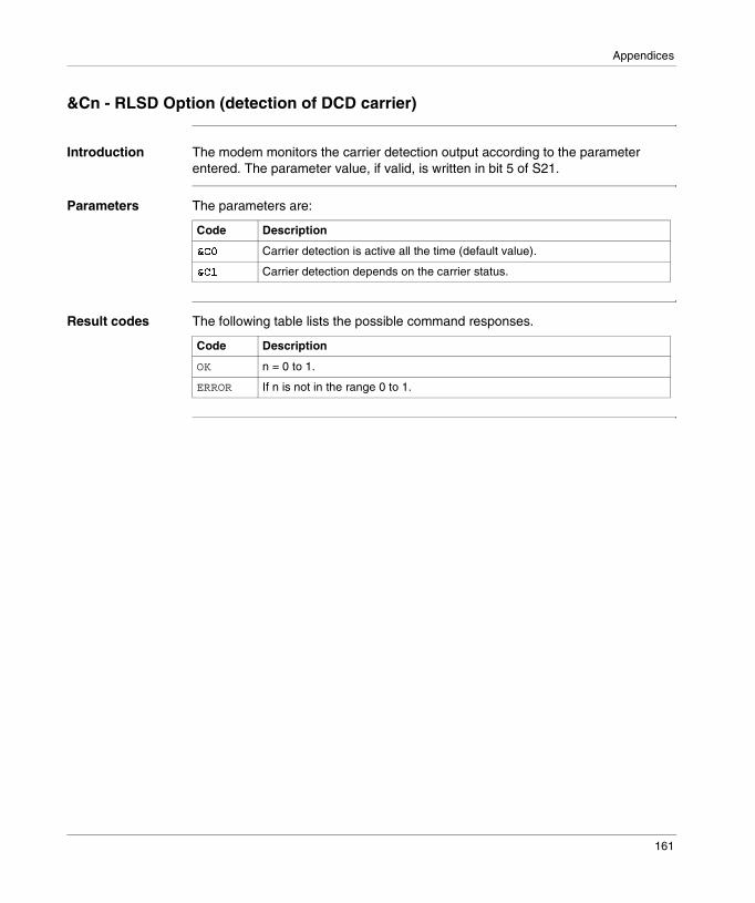
Appendices
&Cn - RLSD Option (detection of DCD carrier)
Introduction The modem monitors the carrier detection output according to the parameter entered. The parameter value, if valid, is written in bit 5 of S21.
Parameters The parameters are:
Result codes The following table lists the possible command responses.
Code Description
23� Carrier detection is active all the time (default value).
23 Carrier detection depends on the carrier status.
Code Description
OK n = 0 to 1.
ERROR If n is not in the range 0 to 1.
161

Appendices
&Dn - DTR Option (Data Terminal Ready)
Introduction This command interprets loss of the DTR signal sent by the DTE, according to the parameter entered. The parameter value, if valid, is written in bits 3 and 4 of S21.
Parameters The parameters are:
Code Description
2�� Loss of the DTR signal is interpreted as follows according to the &Q value in progress (default value):� &Q0,&Q5, &Q6: ignores the DTR signal (assumed activated) and enables
operation with DTEs which do not support DTR signals.� &Q1, &Q4: loss of the DTR signal causes the modem to hang up. There is
no repercussion on automatic answer.� &Q2, &Q3: loss of the DTR signal causes the modem to hang up. Automatic
answer is inhibited.
2� Loss of the DTR signal is interpreted as follows according to the &Q value in progress:� &Q0, &Q1, &Q4, &Q5, &Q6: loss of the DTR signal is interpreted by the
modem as though the synchronous escape sequence had been entered. The modem returns to asynchronous command mode without disconnection.
� &Q2, &Q3: loss of the DTR signal causes the modem to hang up. Automatic answer is inhibited.
2�' Loss of the DTR signal is interpreted as follows according to the &Q value in progress:� &Q0 to &Q6: loss of the DTR signal causes the modem to hang up.
Automatic answer is inhibited.
2�# Loss of the DTR signal is interpreted as follows according to the &Q value in progress:� &Q0, &Q1, &Q4, &Q5, &Q6: loss of the DTR signal causes the modem to
reset the software as though it had received the Z command. The value of &Y defines the profile which is loaded.
� &Q2, &Q3: loss of the DTR signal causes the modem to hang up. Automatic answer is inhibited.
������If &Q5, &Q6, +FCLASS=1 is in use, the result is identical to the &Q0 command.
162

Appendices
&Fn - Restoration of the factory configuration (profile)
Introduction The modem loads the defined factory default configuration according to the parameter entered. The default Rockwell values corresponding to the 0 (&F0) profile are used for each command and in the S register descriptions. Two profiles are available. A configuration profile is made up of a sub-set of S registers.
Parameters The parameters are:
Code Description
24� Reestablishes the factory profile 0 (default value).
24 Reestablishes the factory profile 1.
163

Appendices
&Gn - Selection of guard tone
Introduction The modem generates the guard tone selected by this command according to the parameter entered (differential phase shift modulation modes only). The parameter value, if valid, is written in bits 6 and 7 of S23.
Parameters The parameters are:
Result codes The following table lists the possible command responses.
Code Description
25� Deactivates the guard tone (default value for US models).
25 Deactivates the guard tone.
25' Selects a guard tone of 1800 Hz (default value for W-class models).
������In certain countries, this command may not be authorized.
Code Description
OK n = 0 to 2.
ERROR If n is not in the range 0 to 2.
164

Appendices
&Kn – Flow control
Introduction This command defines the DTE/DCE (terminal/modem) flow control mechanism. The parameter value, if valid, is written in bits 0, 1 and 2 of S39.
Parameters The parameters are:
Result codes The following table lists the possible command responses.
Code Description
26� Deactivates flow control.
26# Activates RTS/CTS flow control - hardware flow control (default value for data modem modes).
26$ Activates XON/XOFF flow control – software flow control.
26% Activates transparent XON/XOFF flow control.
26& Activates RTS/CTS flow control and XON/XOFF flow control at the same time (default value for fax-modem modes).
Code Description
OK n = 0, 3 to 6.
ERROR If n is not equal to 0 or 3 to 6.
165

Appendices
&Pn - Selection of pulse dialing close/open report
Introduction This command determines the close/open report used during pulse dialing. It only has an effect if the appropriate bit activating this command is set by the program ConfigurACE.If the command is activated, it has priority over the close/open reports defined by the OEM parameters in ConfigurACE. The default value depends on the country. The parameter value, if valid, is written in bits 3 and 4 of S28.
Parameters The parameters are:
Result codes The following table lists the possible command responses.
Code Description
2� Selection of 39%-61% as close/open report at 10 pulses per second (default value).
2 Selection of 33%-67% as close/open report at 10 pulses per second.
2' Selection of 39%-61% as close/open report at 20 pulses per second.
2# Selection of 33%-67% as close/open report at 20 pulses per second.
Code Description
OK n = 0 to 3.
ERROR If n is not in the range 0 to 3.
166

Appendices
&Qn - Synchronous/asynchronous mode
Introduction This command monitors the authorized connection modes. It is used in association with S36 and S48 (see also command \N).
Parameters The parameters are:
Result codes The following table lists the possible command responses.
Code Description
2+� Selects direct asynchronous mode.
2+ Selects
2+' Selects
2+$ Selects automatic synchronous mode. The binary value 100 is written in bits 3, 1 and 0 of S27 respectively.
2+% The modem attempts to establish a link with error correction. The mode can be configured with S36 to determine if, in case of failure, the modem hangs up or if it falls back to an asynchronous connection. The binary value 101 is written in bits 3, 1 and 0 of S27 (default value) respectively.
2+& Selects normal asynchronous mode (with baud rate buffer). The binary value 110 is written in bits 3, 1 and 0 of S27 respectively.
Code Description
OK n = 0, 1, 2, ,4, 5, 6.
ERROR If n is not equal to 0, 1, 2, 4, 5, or 6.
167
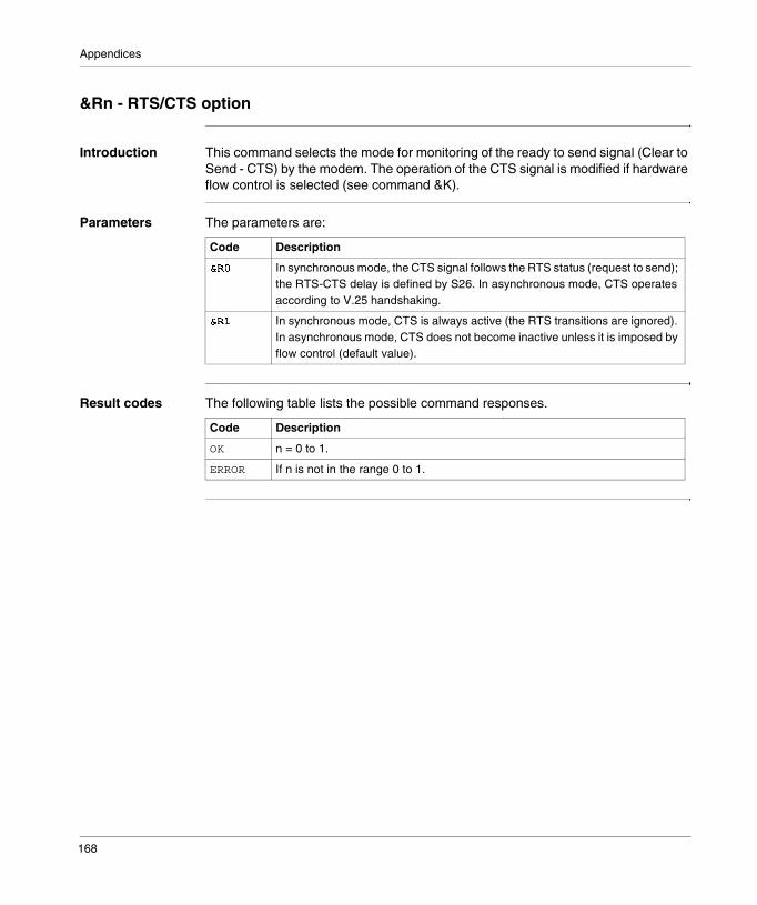
Appendices
&Rn - RTS/CTS option
Introduction This command selects the mode for monitoring of the ready to send signal (Clear to Send - CTS) by the modem. The operation of the CTS signal is modified if hardware flow control is selected (see command &K).
Parameters The parameters are:
Result codes The following table lists the possible command responses.
Code Description
2�� In synchronous mode, the CTS signal follows the RTS status (request to send); the RTS-CTS delay is defined by S26. In asynchronous mode, CTS operates according to V.25 handshaking.
2� In synchronous mode, CTS is always active (the RTS transitions are ignored). In asynchronous mode, CTS does not become inactive unless it is imposed by flow control (default value).
Code Description
OK n = 0 to 1.
ERROR If n is not in the range 0 to 1.
168
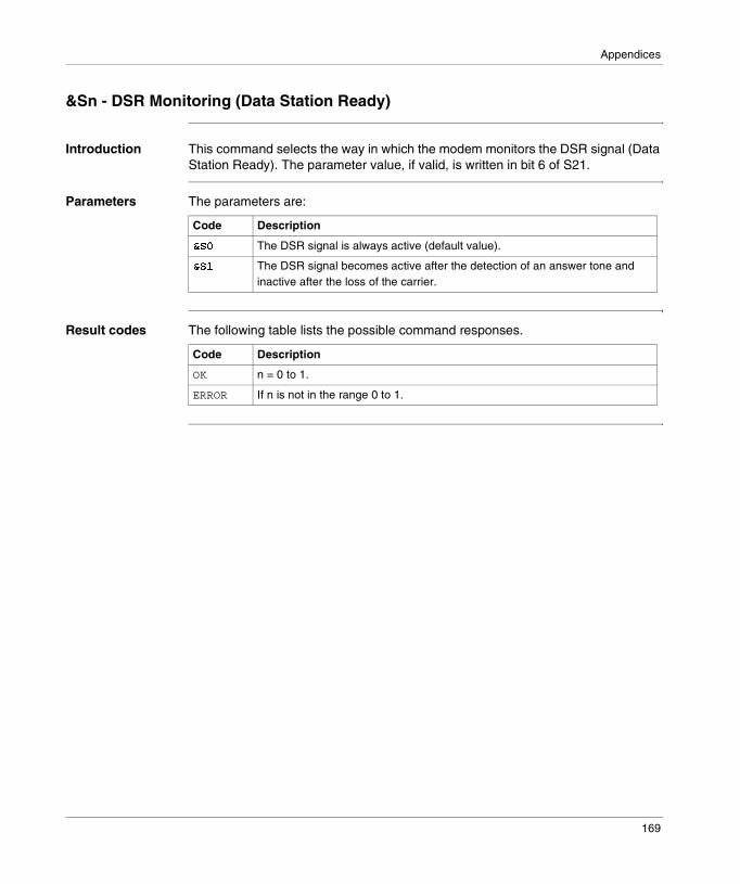
Appendices
&Sn - DSR Monitoring (Data Station Ready)
Introduction This command selects the way in which the modem monitors the DSR signal (Data Station Ready). The parameter value, if valid, is written in bit 6 of S21.
Parameters The parameters are:
Result codes The following table lists the possible command responses.
Code Description
2�� The DSR signal is always active (default value).
2� The DSR signal becomes active after the detection of an answer tone and inactive after the loss of the carrier.
Code Description
OK n = 0 to 1.
ERROR If n is not in the range 0 to 1.
169
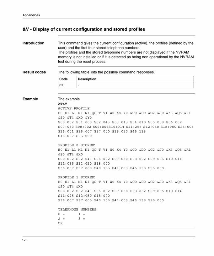
Appendices
&V - Display of current configuration and stored profiles
Introduction This command gives the current configuration (active), the profiles (defined by the user) and the first four stored telephone numbers.The profiles and the stored telephone numbers are not displayed if the NVRAM memory is not installed or if it is detected as being non operational by the NVRAM test during the reset process.
Result codes The following table lists the possible command responses.
Example The example�� !ACTIVE PROFILE:B0 E1 L1 M1 N1 QO T V1 W0 X4 Y0 &C0 &D0 &G2 &J0 &K3 &Q5 &R1 &S0 &T4 &X0 &Y0S00:002 S01:000 S02:043 S03:013 S04:010 S05:008 S06:002 S07:030 S08:002 S09:006S10:014 S11:255 S12:050 S18:000 S25:005 S26:001 S36:007 S37:000 S38:020 S46:138S48:007 S95:000
PROFILE 0 STORED:B0 E1 L1 M1 N1 QO T V1 W0 X4 Y0 &C0 &D0 &G2 &J0 &K3 &Q5 &R1 &S0 &T4 &X0S00:002 S02:043 S06:002 S07:030 S08:002 S09:006 S10:014 S11:095 S12:050 S18:000S36:007 S37:000 S40:105 S41:003 S46:138 S95:000
PROFILE 1 STORED:B0 E1 L1 M1 N1 QO T V1 W0 X4 Y0 &C0 &D0 &G2 &J0 &K3 &Q5 &R1 &S0 &T4 &X0S00:002 S02:043 S06:002 S07:030 S08:002 S09:006 S10:014 S11:095 S12:050 S18:000S36:007 S37:000 S40:105 S41:003 S46:138 S95:000
TELEPHONE NUMBERS:0 = 1 =2 = 3 =OK
Code Description
OK -
170
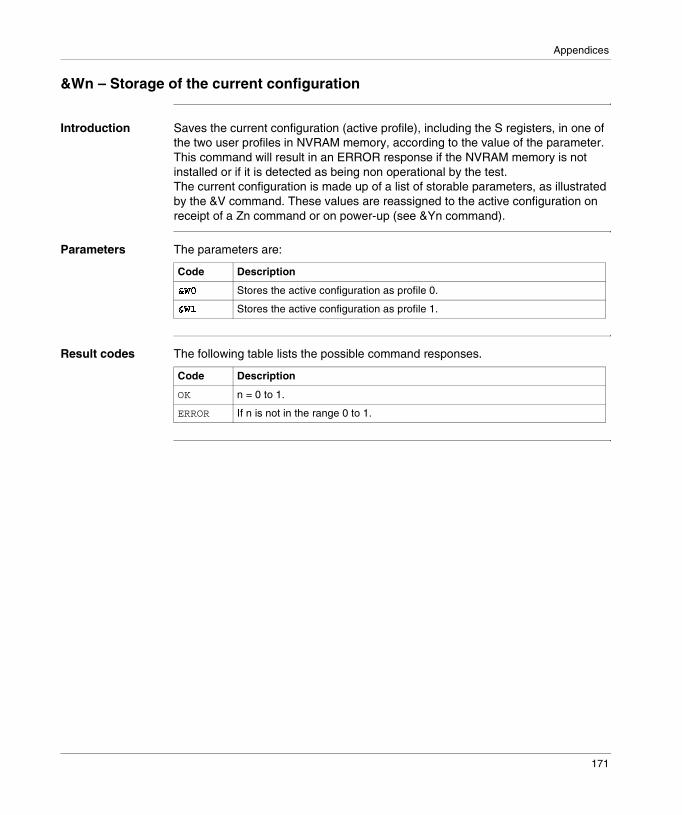
Appendices
&Wn – Storage of the current configuration
Introduction Saves the current configuration (active profile), including the S registers, in one of the two user profiles in NVRAM memory, according to the value of the parameter.This command will result in an ERROR response if the NVRAM memory is not installed or if it is detected as being non operational by the test.The current configuration is made up of a list of storable parameters, as illustrated by the &V command. These values are reassigned to the active configuration on receipt of a Zn command or on power-up (see &Yn command).
Parameters The parameters are:
Result codes The following table lists the possible command responses.
Code Description
2�� Stores the active configuration as profile 0.
2� Stores the active configuration as profile 1.
Code Description
OK n = 0 to 1.
ERROR If n is not in the range 0 to 1.
171

Appendices
&Yn - Designation of a default profile on reset
Introduction Selects the user profile to be loaded after a hardware reset.
Parameters The parameters are:
Result codes The following table lists the possible command responses.
Code Description
20� The modem uses profile 0.
20 The modem uses profile 1.
Code Description
OK n = 0 to 1.
ERROR If n is not in the range 0 to 1.
172

Appendices
&Zn – Storage of telephone numbers
Introduction The modem can store a maximum of 20 telephone numbers. Each telephone number can be up to 45 digits.
Parameters The parameters are:
Result codes The following table lists the possible command responses.
Code Description
21�� �7 n = 0 to 19 (W-class) and x = number string (needs 2048 bytes of NVRAM).
Code Description
OK n = 0 to 19 and x less than or equal to 45 digits.
ERROR If n is greater than 19 or x greater than 45 digits.
173

Appendices
%Cn - Activation / deactivation of data compression
Introduction Activates / deactivates data compression The parameter value, if valid, is written in bits 0 and 1 of S41.
Parameters The parameters are:
Result codes The following table lists the possible command responses.
Code Description
83� Deactivates data compression.
83 Activates MNP 5 data compression.
8�' Activates V.42 bis data compression.
8�# Activates V.42 bis and MNP 5 data compression.
Code Description
OK n = 0 to 3.
ERROR If n is not in the range 0 to 3.
174
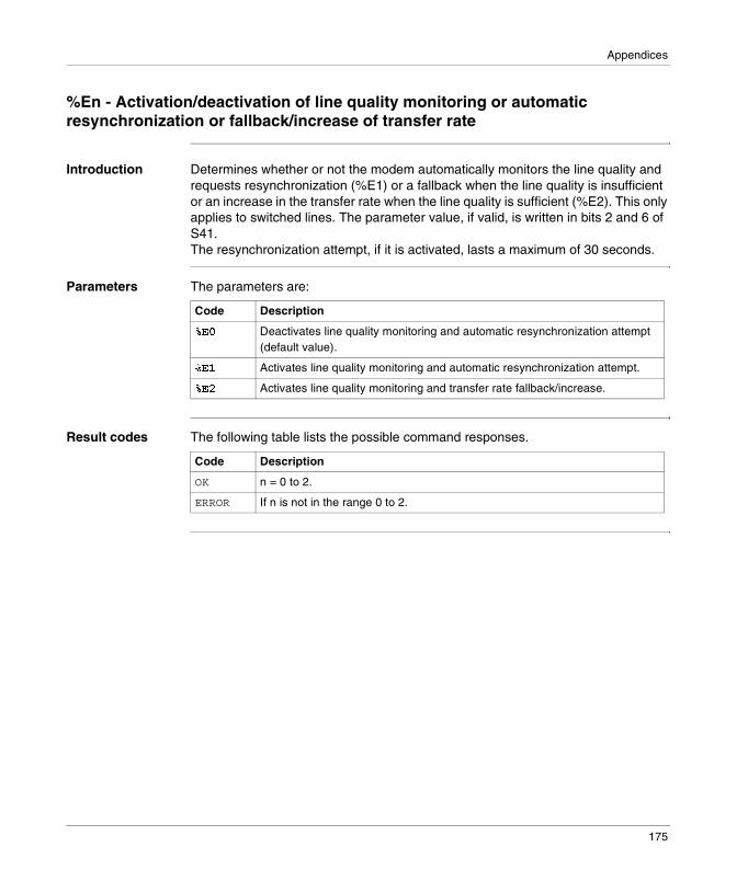
Appendices
%En - Activation/deactivation of line quality monitoring or automatic resynchronization or fallback/increase of transfer rate
Introduction Determines whether or not the modem automatically monitors the line quality and requests resynchronization (%E1) or a fallback when the line quality is insufficient or an increase in the transfer rate when the line quality is sufficient (%E2). This only applies to switched lines. The parameter value, if valid, is written in bits 2 and 6 of S41.The resynchronization attempt, if it is activated, lasts a maximum of 30 seconds.
Parameters The parameters are:
Result codes The following table lists the possible command responses.
Code Description
8�� Deactivates line quality monitoring and automatic resynchronization attempt (default value).
8� Activates line quality monitoring and automatic resynchronization attempt.
8�' Activates line quality monitoring and transfer rate fallback/increase.
Code Description
OK n = 0 to 2.
ERROR If n is not in the range 0 to 2.
175

Appendices
%L - Level of line signal
Introduction Sends back a value which indicates the level of signal received. The returned value is a direct indication of the level of reception at the modem data pumping device, and not at the telephone line connector.For example, 009 = -9 dBm, 043 = -43 dBm, and so on.
Result codes The following table lists the possible command responses.
Code Description
OK n = 0 to 1.
176
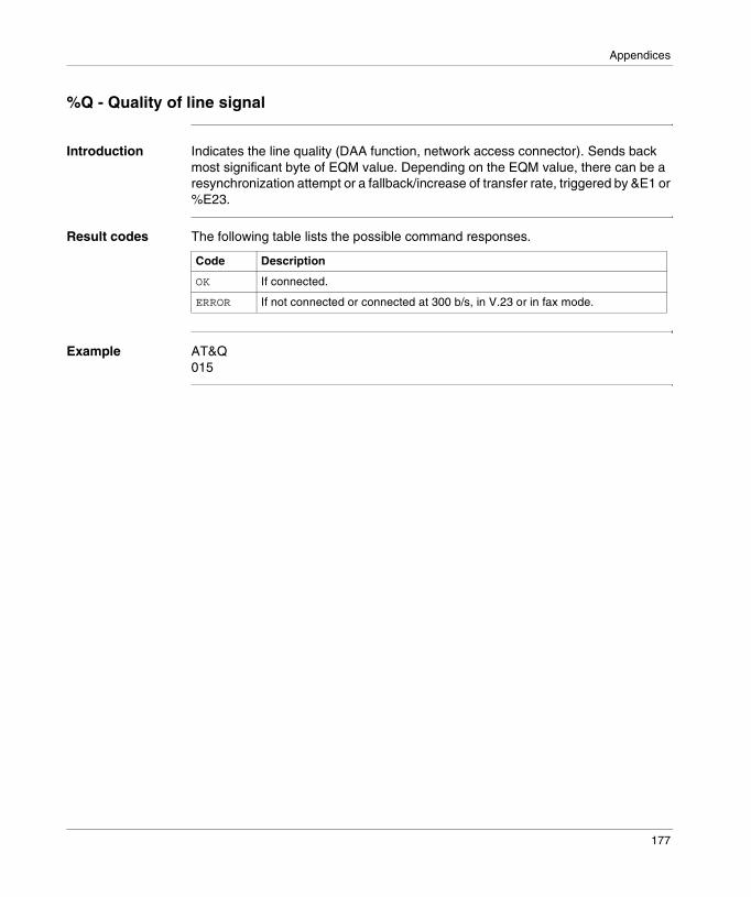
Appendices
%Q - Quality of line signal
Introduction Indicates the line quality (DAA function, network access connector). Sends back most significant byte of EQM value. Depending on the EQM value, there can be a resynchronization attempt or a fallback/increase of transfer rate, triggered by &E1 or %E23.
Result codes The following table lists the possible command responses.
Example AT&Q015
Code Description
OK If connected.
ERROR If not connected or connected at 300 b/s, in V.23 or in fax mode.
177
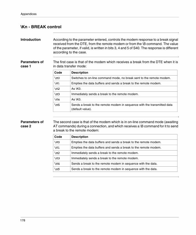
Appendices
\Kn - BREAK control
Introduction According to the parameter entered, controls the modem response to a break signal received from the DTE, from the remote modem or from the \B command. The value of the parameter, if valid, is written in bits 3, 4 and 5 of S40. The response is different according to the case.
Parameters of case 1
The first case is that of the modem which receives a break from the DTE when it is in data transfer mode:
Parameters of case 2
The second case is that of the modem which is in on-line command mode (awaiting AT commands) during a connection, and which receives a \B command for it to send a break to the remote modem:
Code Description
96� Switches to on-line command mode, no break sent to the remote modem.
96 Empties the data buffers and sends a break to the remote modem.
96' As \K0.
96# Immediately sends a break to the remote modem.
96$ As \K0.
96% Sends a break to the remote modem in sequence with the transmitted data (default value).
Code Description
96� Empties the data buffers and sends a break to the remote modem.
96 Empties the data buffers and sends a break to the remote modem.
96' Immediately sends a break to the remote modem.
96# Immediately sends a break to the remote modem.
96$ Sends a break to the remote modem in sequence with the data.
96% Sends a break to the remote modem in sequence with the data.
178
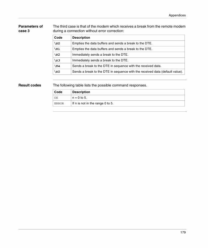
Appendices
Parameters of case 3
The third case is that of the modem which receives a break from the remote modem during a connection without error correction:
Result codes The following table lists the possible command responses.
Code Description
96� Empties the data buffers and sends a break to the DTE.
96 Empties the data buffers and sends a break to the DTE.
96' Immediately sends a break to the DTE.
96# Immediately sends a break to the DTE.
96$ Sends a break to the DTE in sequence with the received data.
96% Sends a break to the DTE in sequence with the received data (default value).
Code Description
OK n = 0 to 5.
ERROR If n is not in the range 0 to 5.
179

Appendices
\Nn - Operating mode
Introduction This command defines the preferred error correction mode to negotiate during a subsequent connection. It is assigned by the configuration of the OEM firmware.
Parameters The parameters are:
Result codes The following table lists the possible command responses.
Code Description
9)� Selects normal mode with baud rate buffer (without error correction mode) (equivalent to &Q6).
9) Serial interface selected – selects direct mode and is equivalent to the operating mode (equivalent to &Q0). Parallel interface selected – as \N0.
9)' Select reliable mode (with error correction). The modem attempts first to establish an LAPM correction then an MNP connection. If it fails, the modem hangs up (equivalent to &Q5, S36=4 and S48=7).
9)# Selects automatic reliable mode. This mode is identical to \N2 mode apart from the fact that if the modem does not manage to establish a reliable connection, it falls back to normal mode (equivalent to &Q5, S36=7 and S48=7).
9)$ Selects LAPM error correction mode. If it fails, the modem hangs up (equivalent to &Q5, and S48=0).
9)% Selects MNP error correction mode. If it fails, the modem hangs up (equivalent to &Q5, S36=4 et S48=128).
Code Description
OK n = 0 to 5.
ERROR If n is not in the range 0 to 5.
180
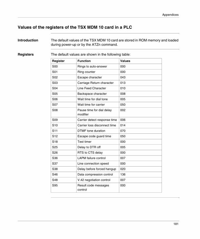
Appendices
Values of the registers of the TSX MDM 10 card in a PLC
Introduction The default values of the TSX MDM 10 card are stored in ROM memory and loaded during power-up or by the ATZn command.
Registers The default values are shown in the following table:
Register Function Values
S00 Rings to auto-answer 000
S01 Ring counter 000
S02 Escape character 043
S03 Carriage Return character 013
S04 Line Feed Character 010
S05 Backspace character 008
S06 Wait time for dial tone 005
S07 Wait time for carrier 050
S08 Pause time for dial delay modifier
002
S09 Carrier detect response time 006
S10 Carrier loss disconnect time 014
S11 DTMF tone duration 070
S12 Escape code guard time 050
S18 Test timer 000
S25 Delay to DTR off 005
S26 RTS to CTS delay 000
S36 LAPM failure control 007
S37 Line connection speed 000
S38 Delay before forced hangup 020
S46 Data compression control 136
S48 V.42 negotiation control 007
S95 Result code messages control
000
181

Appendices
182
III
Communication via Modbus PlusIntroduction
Subject of this part
This part introduces the principles of configuring and communicating with Modbus Plus via PL7 software.
What’s in this Part?
This part contains the following chapters:
Chapter Chapter Name Page
12 General 185
13 Peer Cop service 193
14 Configuring Modbus Plus communication 197
15 Programming Modbus Plus communication 205
16 Debugging Modbus Plus communication 217
17 Language objects associated with Modbus Plus communication
221
183

Communication via Modbus Plus
184

12
GeneralIntroduction
Aim of this Chapter
This Chapter introduces Modbus Plus communication and its services.
What’s in this Chapter?
This chapter contains the following topics:
Topic Page
Introduction 186
Compatibility 187
Integration into an X-WAY architecture 188
Integration into a Modbus Plus architecture 191
185

Modus Plus communication: General
Introduction
Introduction Modbus Plus communication is used to exchange data between all devices connected by the bus.
The Modbus Plus protocol is based on the principle of a logical token bus (Logical Token passing). Each station of one network is identified by an address between 1 and 64 and each station accesses the network after reception of a token. Duplicated addresses are not valid.
Network example
A Modbus Plus communication channel comprises three main functions:� point to point data exchanges via the messaging service, using the Modbus
protocol,� broadcast exchanges of global data between all the stations participating in this
exchange,� multidrop exchanges of specific data via the Peer Cop services.
Associated manuals
If you require further information you should consult the following manuals:
Premium Quantum
Token bus (logic ring)
2 12
Modbus Plus
Title Description
Modbus Plus Network - Installation and planning manual
Detailed description of the set-up procedure for the Modbus Plus network
Micro PLCs - Installation manual Hardware installation
Premium TSX PLCs - Installation manual Hardware installation
186

Modus Plus communication: General
Compatibility
Hardware This type of communication is available for PLCs of at least version V3.0:� Premium via the intermediary of the TSX MBP100 PCMCIA card,� Micro accepting the PCMCIA card described below.
Premium and Micro PLCs do not support redundancy with the TSX MBP 100 card.
Software The PCMCIA TSX MBP 100 card can process 4 communication functions at the same time.
The maximum size of the number of objects per communication function is 125 useful data words (maximum frame of 256 bytes).
In the event of communication of a Premium and Micro PLC with a Quantum PLC, it is necessary to shift addressing. To access a Quantum object with address n, the communication function on the Premium side must have the address n-1.
The Peer Cop service is only supported by Premium PLCs.During configuration of inputs and outputs for the Peer Cop service, it is possible to allocate up to 32 internal words to each connection point in the local bus. The total number of words must not exceed 500 internal words.
������This type of communication is not available with TSX SCY 21601 modules.
187
Modus Plus communication: General
Integration into an X-WAY architecture
Introduction A Modbus Plus segment can be integrated into an X-WAY network architecture.Communications between stations on the different networks are possible under certain conditions of use.
Communication to a Modbus Plus network
A client application connected to a FIPWAY or ETHERNET TCP/IP network can communicate with a Modbus Plus station via the Modbus protocol.In this case, you must indicate the X-WAY network address of the Premium PLC which is connected on the Modbus Plus segment as well as on the FIPWAY network, and the number of the destination Modbus Plus station.
The syntax is as follows:{network number, station number} 0.1. Modbus Plus station number
188

Modus Plus communication: General
Example In this example, the FIPWAY station {5.3} has a Modbus Plus connection and therefore, any remote FIPWAY station which wishes to communicate with a Modbus Plus station (for example station 5) must use this address.
READ_VAR(ADR#{5.3}0.1.5, ’%MW’, 100, 10,%MW200:10, %MW300:4)Configuration example
Communication from a Modbus Plus network
If a Modbus Plus segment is integrated into an X-WAY architecture, a Quantum station cannot communicate with stations connected to another network in this architecture (for example FIPWAY or ETHERNET TCP/IP). Communication is only possible with the local Premium.
FIPWAY #5
Modbus Plus
Quantum
QuantumPremium
5
3
8
READ_VAR(ADR#{5.3}0.1.5, ’%MW’, 100, 10,%MW200:10, %MW300:4)
������Routing between FIPWAY and Modbus Plus is carried out by the automatic system. In a network architecture, it is not necessary to declare a bridge station.
189

Modus Plus communication: General
Example The Quantum PLC sends a write request to modify 5 words in the PL7 application (%MW10, .etc.), but it does not have access to the other stations on Fipway.
Quantum
FIPWAY #5
Modbus Plus
Premium
5
3
MBP-MSTRwrite510RP=5.0.0.0.0
190

Modus Plus communication: General
Integration into a Modbus Plus architecture
Introduction In a Modbus Plus architecture, a Quantum PLC application can communicate with a Premium PLC and vice versa.
Premium to Quantum
Communication from a Premium PLC to a remote station is described in the exchange service on remote networks.
Quantum to Premium
Communication from a Quantum PLC to a Premium PLC is available via MSTR blocks.In this case, the Premium or Micro are servers; therefore, all Modbus Plus stations connected to a network architecture, up to a maximum of 5 levels, can communicate with them.
Example
The Quantum station sends a read request to the Premium station using an address path: 8.5.1.0.0 (routing path).The MSTR function block is used to read or write internal words of a Premium or Micro station. The parameter of the slave register of the MSTR function block directly indicates the address of the internal word %MW of the PL7 application. This function block is also used to read or reset the statistics counters of a Premium or Micro station. This request is executed directly by the PCMCIA card which responds directly.
QuantumPremium
Quantum
Quantum
Bridge Plus
Bridge Plus
Modbus Plus
Modbus Plus
Modbus Plus1 2 3
5
8
4
MSTRread
191

Modus Plus communication: General
192

13
Peer Cop servicePeer Cop service
Introduction The Peer Cop service is an automatic exchange mechanism between stations connected to the same local Modbus Plus segment.This service is used to maintain constant control over inputs / outputs which have been remoted by implicit exchanges.
The Premium PLCs support two types of Peer Cop transfer.� specific inputs, � specific outputs.
Specific inputs and outputs
The specific inputs and outputs are point to point services which use the multicast protocol (multistations). Each message contains one or several destination addresses for sending the data. This function is used to exchange data to several stations without repetition.
Report Three types of report are associated with the specific inputs and outputs:� activity bit: provides information on the availability and validity of the status bits,� status bits (to the number of one bit per station):
� ensure coherence between the number of specific inputs configured and the number of specific inputs received,
� indicate if the specific inputs have been received during the Timeout,� presence bits (to the number of one bit per station): indicate if the specific inputs
have been refreshed.
������The presence bits are only valid for the specific inputs.
193

Communication Modbus Plus: Peer Cop service
Example for the inputs
The data blocks are copied in full from the PCMCIA card to the internal word space, reserved during configuration.
In the following example, the address of the first internal word is %MW10:
%MW103 words from station 1
%MW1332 words from station 5
%MW4520 words from station 6
%MW6512 words from station 8
%MW7732 words from station 9
%MW1503 words from station 62
Peer Cop data specific inputs
Station 1
Station 5
Station 6
Station 62
Activity bit
Status bits
Presence bits
Max. 500 characters
%IW0.1.6%IW0.1.7
...%IW0.1.14
copy
copy
Internal words PCMCIA card Modbus Plus network
194

Communication Modbus Plus: Peer Cop service
Example for the outputs
The data blocks are copied in full from the internal word space, reserved during configuration, to the PCMCIA card. The reports are copied from the PCMCIA card to the language objects.
In the following example, the address of the first internal word is %MW10:
%MW103 words from station 1
%MW1332 words of station 5
%MW4520 words of station 6
%MW6512 words from station 8
%MW7732 words from station 9
%MW1503 words from station 62
Specific outputsPeer Cop data
Station 1
Station 5
Station 6
Activity bit
Status bits
Max. 500 characters
%IW0.1.6%IW0.1.7
...%IW0.1.14
copy
copy
Internal words PCMCIA card Modbus Plus network
Station 1
Station 5
Station 6
Station 62
Station 62
195

Communication Modbus Plus: Peer Cop service
196
14
Configuring Modbus Plus communicationIntroduction
Subject of Chapter
This Chapter describes the Configuration process during set-up of Modbus Plus communication.
What’s in this Chapter?
This chapter contains the following topics:
Topic Page
How to access the Modbus Plus PCMCIA card parameters 198
Modbus Plus configuration screen 199
Functions accessible from Modbus Plus 200
Modbus Plus configuration parameters 201
Configuring the specific inputs and outputs 202
197

Modbus Plus configuration
How to access the Modbus Plus PCMCIA card parameters
Introduction This operation describes how to access the configuration parameters of the Modbus Plus link via the intermediary of the PCMCIA cards for Premium PLCs.
How to access the link
The following table shows the procedure for accessing the Modbus Plus link:
Step Action
1 Access the communication channel configuration screen.
2 Select the communication channel from the drop-down menu CHANNEL 1Example
3 Select the PCMCIA card from the drop-down menu TSX MBP 100 MODBUS+ PCMCIA CARD :Example
CHANNEL 1 CHANNEL 1:
(No PCMCIA submodule)
(Link not configured) MASTCHANNEL 0CHANNEL 1
CHANNEL 1 CHANNEL 1
(No PCMCIA submodule)
(Link not configured) MASTTSX FPP 20 FIPWAY PCMCIA CARDTSX FPP 200 FIPWAY PCMCIA CARDTSX FPP 10 FIPIO PCMCIA CARDTSX FPP 100 MODBUS+ PCMCIA CARDTSX MDM 10 MODEM PCMCIA CARDFCS SCP 111 RS232 OPEN PCMCIA CARDFCS SCP 114 RS485 OPEN PCMCIA CARD
198

Modbus Plus configuration
Modbus Plus configuration screen
Introduction This screen, split into two zones, is used to declare the communication channel and to configure the parameters necessary for a Modbus Plus link.
Illustration The screen dedicated to Modbus Plus communication looks like this:
Elements and functions
This table describes the different zones that make up the configuration screen:
�������������������� ����������
Configuration
Designation: PROCESSOR TSX P 57302
TSX MBP 100 MODBUS+ PCMCIA CARD
CHANNEL 1:
MODBUS+ MAST
500
1
Peer Cop
Station number: :
Input fallback mode
Value of Timeout: (ms)
MaintainReset to 0
�
�
CHANNEL 1
Specific Inputs
Specific outputs
Address Zone Function
1 common (See : PL7 Micro/Junior/Pro ; Communication applications ; Volume 1)
2 specific is used to select or complete the parameters of a Modbus Plus link.It is split into two types of information:� station addressing,� the parameters concerning the Peer Cop service.
199

Modbus Plus configuration
Functions accessible from Modbus Plus
Introduction Depending on the chosen communication supports, some parameters cannot be modified. They appear grayed out.
Accessible functions
The summary table below shows the various choices possible:
Functions TSX MPB 100
Station number For processors of at least version V3.0
Peer Cop For processors of at least version V3.3
Input fallback mode Accessible if the Peer Cop box is checked
Specific inputs Accessible if the Peer Cop box is checked
Specific outputs Accessible if the Peer Cop box is checked
200
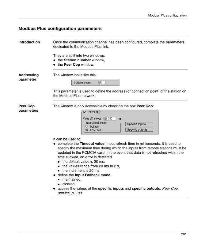
Modbus Plus configuration
Modbus Plus configuration parameters
Introduction Once the communication channel has been configured, complete the parameters dedicated to the Modbus Plus link.
They are split into two windows:� the Station number window,� the Peer Cop window,
Addressing parameter
The window looks like this:
This parameter is used to define the address (or connection point) of the station on the Modbus Plus network.
Peer Cop parameters
The window is only accessible by checking the box Peer Cop:
It can be used to: � complete the Timeout value: Input refresh time in milliseconds. It is used to
specify the maximum time during which the inputs from remote stations must be updated in the PCMCIA card. In the event that data is not refreshed within the time allowed, an error is detected.� the default value is 20 ms,� the values range from 20 ms to 2 s,� the increment is 20 ms.
� define the Input Fallback mode:� maintained,� cleared.
� access the values of the specific inputs and specific outputs. Peer Cop service, p. 193
1Station number: :
500
Peer Cop
Input fallback mode
Value of Timeout: (ms)
MaintainReset to 0
Specific Inputs
Specific outputs
201

Modbus Plus configuration
Configuring the specific inputs and outputs
Introduction If you have checked the box Peer Cop, you must specify the start address and the size of the data to be exchanged.
These data are stored in the internal words of the application. Peer Cop service, p. 193
Configuration rules
The input words zone cannot be superimposed on the output words zone.The internal words corresponding to the specific inputs or outputs are stored continuously.The maximum size of the specific data must not exceed 1000 words (max. 500 words for the inputs and max. 500 words for the outputs).
Specific inputs After selection of the button Specific inputs, the following window will appear:
For each connection point of the local bus segment, the user must define:� the start address in the table of internal words (%MW),� The size of the exchanges from 0 to 32 words per station on the local bus
segment.
%MW
%��!�&�'�((��)
15932
416133219
234
6789
10
5 28
�� (�������Validate
Cancel
Address of 1st %MW10
�����*���*��
%MW10%MW15%MW24
%MW84%MW88
%MW104%MW117%MW149
%MW56
202

Modbus Plus configuration
Specific outputs After selection of the button Specific outputs, the following window will appear:
For each connection point of the local bus segment, the user must define:� the start address in the table of internal words (%MW),� The size of the exchanges from 0 to 32 words per station on the local bus
segment.
%MW
%��!�&�'�((��)
15615
26312211
234
6789
10
5 32
�� (�������Validate
Cancel
Address of 1st %MW100
�����*����*���
%MW100%MW105%MW111
%MW158%MW184%MW187%MW199%MW220
%MW126
203

Modbus Plus configuration
204

15
Programming Modbus Plus communicationIntroduction
Subject of Chapter
This Chapter describes the Programming process during set-up of Modbus Plus communication.
What’s in this Chapter?
This chapter contains the following topics:
Topic Page
Read and write service on local segment 206
Exchange service on remote Modbus Plus networks 208
Examples of Exchanges on Remote Networks 210
Diagnostic service 213
Global data exchange service 215
205

Modbus Plus programming
Read and write service on local segment
Introduction A Micro or Premium PLC can exchange data with stations connected to the local Modbus Plus network.
Data exchanges The functions READ_VAR and WRITE_VAR are used to access remote stations on the same local segment, bits, internal words or input and output words in read / write mode.These exchanges are explicit exchanges managed by the application.
The addressing from a Premium station will be for example:� in read mode
READ_VAR (ADR#0.1.10, ’%MW’, 10, 20, %MW10:20, %MW100:4)� in write mode
WRITE_VAR (ADR#0.1.10, ’%MW’, 10, 20, %MW10:20, %MW100:4)The following table describes the different parameters of the function:
Parameter Description
ADR#0.1.10 Address of destination device for the message:� processor slot: 0 or 1� PCMCIA channel: 1� destination station number: 10
’%MW’ Type of object to be read or written, for example: internal words
10 Address of first word to be read or written
20 Number of words to be read or written
%MW10:20 For reading: content of responseFor writing: value of words to be written
%MW100:4 Activity bit, exchange report, length
206

Modbus Plus programming
Correspondence of object type
The tables describe the correspondence of object types between the Premium and Quantum PLCs.
The Premium PLC is the sender of the request and the Quantum PLC replies:
The Quantum PLC is the sender via an MSTR function block and the Premium PLC replies:
Example The Premium PLC application writes 10 internal words in the Quantum PLC at address 2 and reads 5 input words in the Quantum PLC at address 5:
The internal words to be written in station 2 are at address 10.The internal words to be read in station 5 are at address 5.
����:.�� or ��"�:.�� function
Type of PL7 object Responding Quantum object
’%MW’ internal words 4x... memory area
’%M’ internal bits 0x... memory area
’%IW’ input words 3x... memory area
’%I’ input bits 1x... memory area
MSTR function block Responding Premium object
READ %MW
WRITE %MW
Quantum
Quantum
2 51
WRITE_VAR(ADR#0.1.2, ‘%MW’, 10, 5, %MW100:5, %MW200:4)
READ_VAR(ADR#0.1.5, ‘%IW’, 5, 8, %MW100:5, %MW200:4)
207

Modbus Plus programming
Exchange service on remote Modbus Plus networks
Introduction A Micro or Premium PLC can exchange data with stations connected to other Modbus Plus segments via BP85 Bridge Plus bridges.
Access to a remote station.
To access a station connected to another network segment, it is necessary to indicate the full address path (routing path) in the information sent. Beforehand, indicate, in the request, the address of the first destination connection point on the local bus.Next, clarify, in the data to be sent, each address of the devices which will allow the passage of the exchanges to the destination station.
Data exchanges This type of exchange is accessible via the function SEND_REQ. To differentiate the reading and writing of data from a remote station, a request code is associated to the function SEND_REQ. These exchanges are explicit exchanges managed by the application.
The addressing from a Premium station will be for example:� in read mode
SEND_REQ (ADR#0.1.61, 16#36, %MW300:50, %MW450:150, %MW600:4)
� in write modeSEND_REQ (ADR#0.1.61, 16#37, %MW300:50, %MW450:150, %MW600:4)
The following table describes the different parameters of the function:
Parameters Description
ADR#0.1.61 Address of destination device for the message:� processor slot: 0 or 1� PCMCIA channel: 1� number of the destination connection point on the local bus:
61
16#3616#37
Request code for reading objectsRequest code for writing objects
%MW300:50 Address path, length, data to be sent
%MW450:150 Address, length of data to be received
%MW600:4 Activity bit, exchange report, length
208

Modbus Plus programming
Data coding The data of read / write requests are encoded in internal words, to be sent in the following way:
%MW300 %MW301 %MW302 %MW303 %MW304
Thirdaddress
Secondaddress
Fifthaddress
Fourthaddress
Type Segment Address offirst word
Size of data Data
%MW306to%MW349
209

Modbus Plus programming
Examples of Exchanges on Remote Networks
At a Glance The following illustration shows the two types, which are processed below:
Quantum Quantum
Quantum
Quantum
Modbus Plus
Premium
BP85Bridge Plus
BP85Bridge Plus
BP85Bridge Plus
Bridgemultiplexer
MasterA
SlaveA
Modem
Modem
Modem
Slave49
Slave69
22 13 61
15 253012
7 224
962
4321
210

Modbus Plus programming
Example 1 Reading, using a Premium PLC, of 120 internal words at address 80 of the Quantum station (local address 62) requires:� The routing path to access the Quantum station: 61, 30, 22, 62, 0.� The read request code: 16#36.� The actual size of data to be transferred (latched in %MW603): 10 bytes.
SEND_REQ(ADR#0.1.61, 16#36, %MW300:5, %MW450:120, %MW600:4)
Coding of the data to be transferred:
Parameters Values Description
%MW300 0x161E Second and third crossing point addresses (30, 22)
%MW301 0x003E Fourth and fifth crossing point addresses (62, 0)
%MW302 0x0768 Segment 104 and type 7 (according to the type of variable to be read or written)
%MW303 80 Address of the first internal word to be read in the Quantum station
%MW304 120 Size of data to be read (in words)
No data
������After the execution of the SEND_REQ function, it is necessary to reclassify the bytes in the correct order.
211

Modbus Plus programming
Example 2 Writing, using a Premium PLC, of 50 internal words at address 560 of slave 49 connected to port 4 of the multiplexer bridge requires:� The routing path to access the slave: 61, 25, 4, 49, 0.� The write request code: 16#37.� The actual size of the data to be transmitted (memorized in %MW603): 110 bytes.� The values of the data to be written (latched in %MW305 to %MW354).� The response (latched in %MW450:1): does not contain any data to be received,
but should have a minimum length of a word.
SEND_REQ(ADR#0.1.61, 16#37, %MW300:55, %MW450:1, %MW600:4)
Coding of the data to be transferred:
Parameters Values Description
%MW300 0x0419 Second and third crossing point addresses (25, 4)
%MW301 0x0071 Fourth and fifth crossing point addresses (49, 0)
%MW302 0x0768 Segment 104 and type 7 (according to the type of variable to be read or written)
%MW303 560 Address of the first internal word to be written in the Quantum station
%MW304 50 Size of the data to be written (in words)
%MW305 to %MW354
Data to be written
%MW603 110 Actual size of the data to be transmitted with this function (in bytes)
212
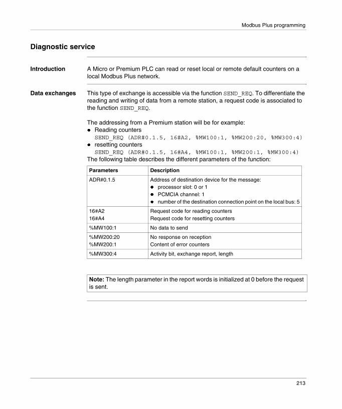
Modbus Plus programming
Diagnostic service
Introduction A Micro or Premium PLC can read or reset local or remote default counters on a local Modbus Plus network.
Data exchanges This type of exchange is accessible via the function SEND_REQ. To differentiate the reading and writing of data from a remote station, a request code is associated to the function SEND_REQ.
The addressing from a Premium station will be for example:� Reading counters
SEND_REQ (ADR#0.1.5, 16#A2, %MW100:1, %MW200:20, %MW300:4)� resetting counters
SEND_REQ (ADR#0.1.5, 16#A4, %MW100:1, %MW200:1, %MW300:4)The following table describes the different parameters of the function:
Parameters Description
ADR#0.1.5 Address of destination device for the message:� processor slot: 0 or 1� PCMCIA channel: 1� number of the destination connection point on the local bus: 5
16#A216#A4
Request code for reading countersRequest code for resetting counters
%MW100:1 No data to send
%MW200:20%MW200:1
No response on receptionContent of error counters
%MW300:4 Activity bit, exchange report, length
������The length parameter in the report words is initialized at 0 before the request is sent.
213

Modbus Plus programming
Counter list The following table shows the counters.
Number of the counter
Meaning
1 Retransmit deferral error counter
2 Receive buffer DMA overrun error counter
3 Repeated command received counter
4 Frame size error counter
5 Receiver collision abort error counter
6 Receiver alignment error counter
7 Receiver CRC error counter
8 Bad-packet-length error counter
9 Bad link address error counter
10 Transmit buffer DMA underrun error counter
11 Bad internal packet length error counter
12 Bad mac function code error counter
13 Communication retry counter
14 Communication failed error counter
15 Good receive packet success counter
16 No response received error counter
17 Exception response received error counter
18 Unexpected path error counter
19 Unexpected response error counter
20 Forgotten transaction error counter
214

Modbus Plus programming
Global data exchange service
Introduction The global data exchange service is a simple exchange mechanism which is used to send broadcast messages between stations connected on the same Modbus Plus network.
During an exchange, a station which has the token can broadcast words destined for other stations connected on the network. A receiving station takes the content of words transmitted by the sending station, stores them in its PCMCIA card and sends them back to the network. The same applies to each station when the token is passed.
To read the global data which is sent, the application of the receiving station must read its PCMCIA card.
Precautions for use
For Premium and Micro PLCs, this service is provided by particular communication functions (WRITE_GDATA and READ_GDATA) periodically taken on by the application. It is not integrated in the Peer Cop transactions.
A Premium or Micro PLC can broadcast a maximum of 32 words.
Writing global data
This type of exchange is accessible via the function WRITE_GDATA.
The addressing from a Premium station will be for example:WRITE_GDATA (ADR#0.1.SYS, %MW100:x, %MW200:4)
The following table describes the different parameters of the function:
������Data transfer from one station to another is automatic.
Parameters Description
ADR#0.1.SYS Broadcast address:� processor slot: 0 or 1� PCMCIA channel: 1� system channel: transmission for all the stations on the
network
%MW100:x Content of the global data to be transmitted (x = 1 to 32 words)
%MW200:4 Activity bit, exchange report, length
215
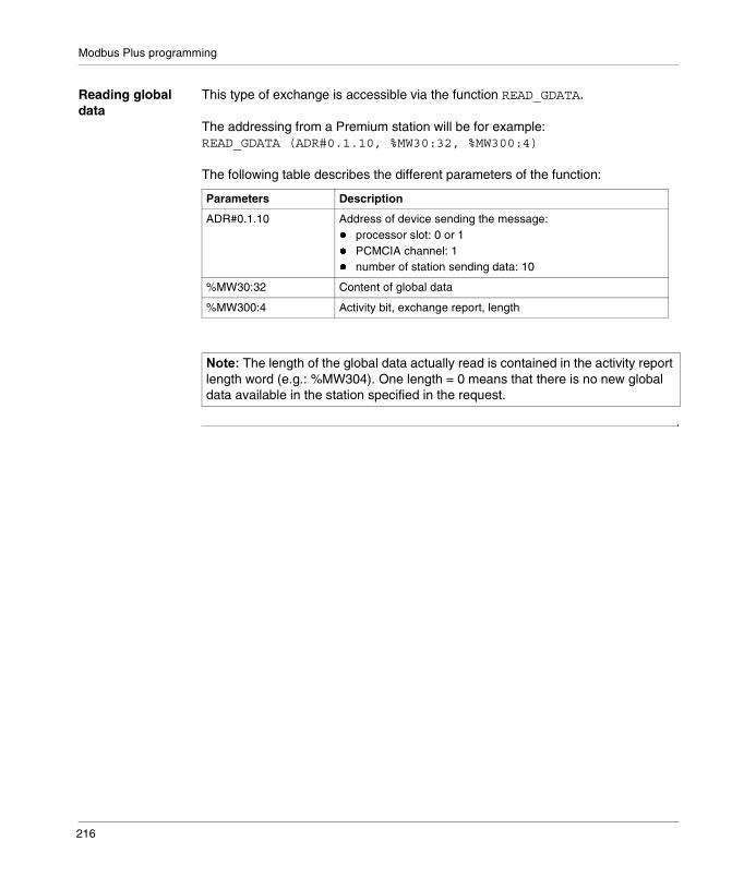
Modbus Plus programming
Reading global data
This type of exchange is accessible via the function READ_GDATA.
The addressing from a Premium station will be for example:READ_GDATA (ADR#0.1.10, %MW30:32, %MW300:4)
The following table describes the different parameters of the function:
Parameters Description
ADR#0.1.10 Address of device sending the message:� processor slot: 0 or 1� PCMCIA channel: 1� number of station sending data: 10
%MW30:32 Content of global data
%MW300:4 Activity bit, exchange report, length
������The length of the global data actually read is contained in the activity report length word (e.g.: %MW304). One length = 0 means that there is no new global data available in the station specified in the request.
216
16
Debugging Modbus Plus communicationIntroduction
Subject of Chapter
This Chapter describes the Debugging process during set-up of Modbus Plus communication.
What’s in this Chapter?
This chapter contains the following topics:
Topic Page
Modbus Plus debugging screen 218
Modbus Plus debugging screen 219
217
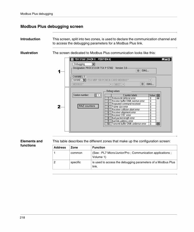
Modbus Plus debugging
Modbus Plus debugging screen
Introduction This screen, split into two zones, is used to declare the communication channel and to access the debugging parameters for a Modbus Plus link.
Illustration The screen dedicated to Modbus Plus communication looks like this:
Elements and functions
This table describes the different zones that make up the configuration screen:
�
�
CHANNEL 1
�������������������� ����������
CHANNEL 1
Designation: PROCESSOR TSX P 57302 Version: 3.0
TSX MBP 100 PCMCIA CARD MODBUS*
MODBUS* MAST
Debugging
Station number:
DIAG...
DIAG...
Debug values
Transmit buffer DMA underrun error
Counter labels Value1 0
000000000
234
6789
10
5
Bad link address errorBad-packet-length errorReceiver CRC error
Receiver collision abort errorReceiver alignment error
Frame size errorRepeated command receivedReceive buffer DMA overrun errorRetransmit deferral error
RAZ counters
1
Address Zone Function
1 common (See : PL7 Micro/Junior/Pro ; Communication applications ; Volume 1)
2 specific is used to access the debugging parameters of a Modbus Plus link.
218
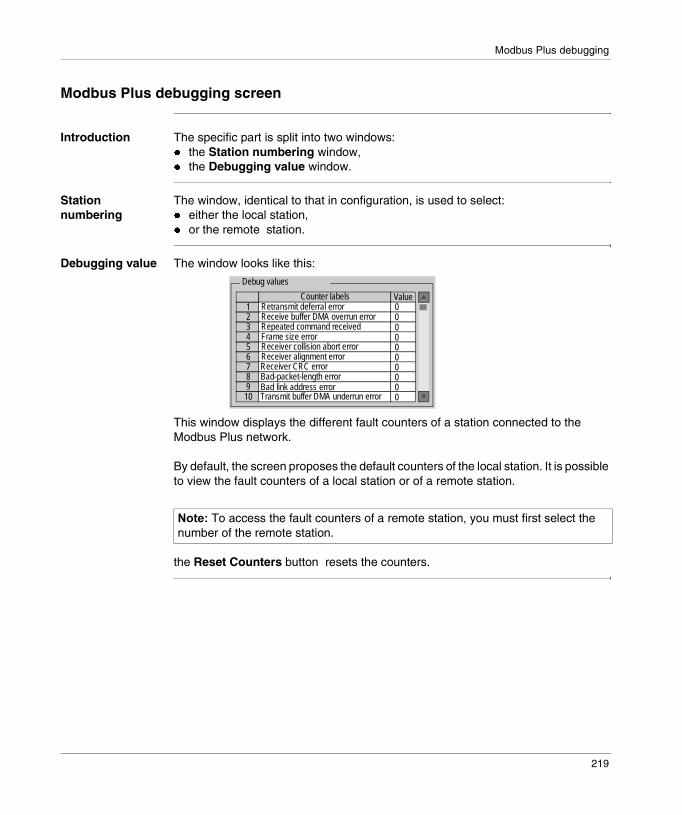
Modbus Plus debugging
Modbus Plus debugging screen
Introduction The specific part is split into two windows:� the Station numbering window,� the Debugging value window.
Station numbering
The window, identical to that in configuration, is used to select:� either the local station,� or the remote station.
Debugging value The window looks like this:
This window displays the different fault counters of a station connected to the Modbus Plus network.
By default, the screen proposes the default counters of the local station. It is possible to view the fault counters of a local station or of a remote station.
the Reset Counters button resets the counters.
������To access the fault counters of a remote station, you must first select the number of the remote station.
Debug values
Transmit buffer DMA underrun error
Counter labels Value1 0
000000000
234
678910
5
Bad link address errorBad-packet-length errorReceiver CRC error
Receiver collision abort errorReceiver alignment error
Frame size errorRepeated command receivedReceive buffer DMA overrun errorRetransmit deferral error
219

Modbus Plus debugging
220
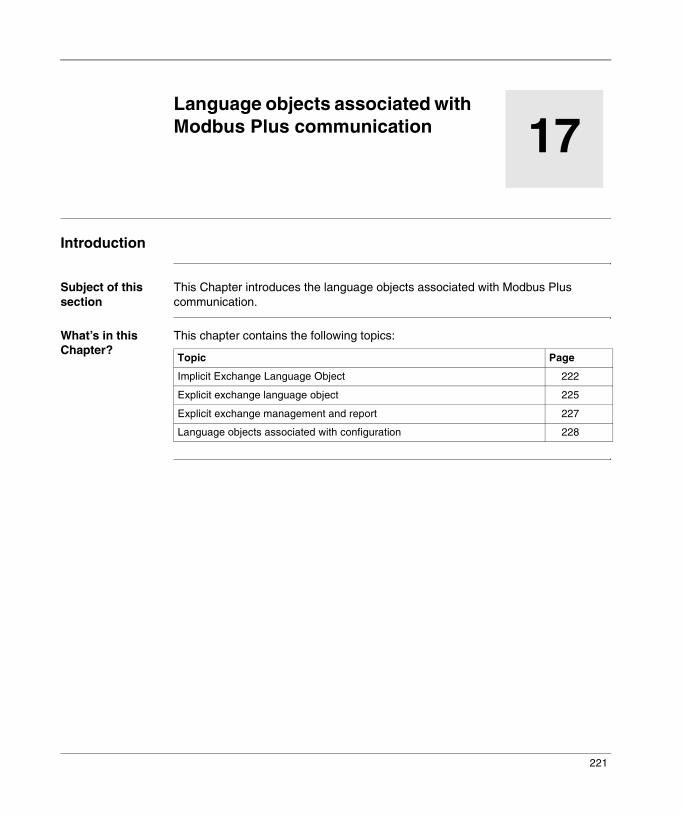
17
Language objects associated with Modbus Plus communicationIntroduction
Subject of this section
This Chapter introduces the language objects associated with Modbus Plus communication.
What’s in this Chapter?
This chapter contains the following topics:
Topic Page
Implicit Exchange Language Object 222
Explicit exchange language object 225
Explicit exchange management and report 227
Language objects associated with configuration 228
221

Modbus Plus language objects
Implicit Exchange Language Object
At a Glance This page describes all implicit exchange language objects for Modbus Plus communication, which can be displayed or modified by the application program (PL7 Micro/Junior/Pro ; Communication applications ; Volume 1).
Bit Objects The table below shows the different bit objects for implicit exchange.
Word Objects The table below shows the different word objects for implicit exchange.
Object (1) Function Meaning
%Ixy.MOD.ERR Module error bit This bit, when set to 1, indicates a module error (at least one of the channels has an error)
%Ixy.i.ERR Channel error bit When this bit is at 1, it indicates a line fault.
Key
(1) Address xy.i� x: corresponds to the rack number� y: corresponds to the module number� i: corresponds to the channel number
Object (1) Function Meaning
%IWxy.i.0 Requests Status of communication pathsByte 0: number of communication functions processed simultaneously in client mode� x0 = 1: communication function 1� x1 = 1: communication function 2� x2 = 1: communication function 3� x3 = 1: communication function 4Byte 1: number of communication functions processed simultaneously in server mode� x8 = 1: communication function 1� x9 = 1: communication function 2� x10 = 1: communication function 3� x11 = 1: communication function 4
%IWxy.i.1 Reserved -
222

Modbus Plus language objects
%IWxy.i.2 to %IWxy.i.5
Periodic exchanges When set to 1, the bit from rank j indicates that the station’s global data is operational, and that the station takes part in the token exchange.� where j = 0 to 15 of word %IWxy.i.2:xj for stations
1 to 16,� where j = 0 to 15 of word %IWxy.i.3:xj for stations
17 to 32,� where j = 0 to 15 of word %IWxy.i.4:xj for stations
33 to 48,� where j = 0 to 15 of word %IWxy.i.5:xj for stations
49 to 64.Example: bit 5 of word %IWxy.i.3:x5 indicates that station 22 takes part in global data exchange.The bit from rank j is reset to 0 when the global data is read by the application (GetGlobalData, command 0x0A) or in the case of a STOP/RUN by the PLC.
%IWxy.i.6 Status bit availability Byte 0: the specific inputs of all remote stations are available� x0 = 0: the specific inputs are not available� x0 = 1: the specific inputs are available� x1 to x7: reserved
Status of the specific inputs
Byte 1: a bit at 1 indicates the presence of a station that is transmitting specific inputs. Stations 1 to 8.
%IWxy.i.7 to %IWxy.i.9
Status of the specific inputs
A bit at 1 indicates the presence of a station that is transmitting specific inputs. Stations 9 to 56.
%IWxy.i.10 Status of the specific inputs
Byte 0: a bit at 1 indicates the presence of a station that is transmitting specific inputs. Stations 57 to 64.
New presence of specific inputs
Byte 1: a bit at 1 indicates the presence of new specific inputs. Stations 1 to 8.
%IWxy.i.11 to %IWxy.i.13
New presence of specific inputs
A bit at 1 indicates the presence of new specific inputs. Stations 9 to 56.
%IWxy.i.14 New presence of specific inputs
Byte 0: a bit at 1 indicates the presence of new specific inputs. Stations 57 to 64.Byte 1: not used
Object (1) Function Meaning
223

Modbus Plus language objects
%IWxy.i.15 Status bit availability Byte 0: the specific outputs are available for all remote stations� x0 = 0: the specific outputs are not available� x0 = 1: the specific outputs are available� x1 to x7: reserved
Status of the specific outputs
Byte 1: a bit at 1 indicates the presence of a station that is receiving specific outputs. Stations 1 to 8.
%IWxy.i.16 to %IWxy.i.18
Status of the specific inputs
A bit at 1 indicates the presence of a station that is receiving specific outputs. Stations 9 to 56.
%IWxy.i.19 Status of the specific inputs
Byte 0: a bit at 1 indicates the presence of a station that is receiving specific outputs. Stations 57 to 64.Byte 1: not used
Key
(1) Address xy.i� x: corresponds to the rack number� y: corresponds to the module number� i: corresponds to the channel number
Object (1) Function Meaning
224

Modbus Plus language objects
Explicit exchange language object
Introduction This page describes all the language objects for explicit exchange in Modbus Plus communication that can be displayed or modified by the application program (PL7 Micro/Junior/Pro ; Communication applications ; Volume 1).
Word objects The table below shows the different word objects for explicit exchange.
Object (1) Function Meaning
%MWxy.MOD.2 Module status � x0 = 1: defective module� x1 = 1: functional error (error between the
processor and the module, adjustment or configuration error, …)
� x2 = 1: terminal block fault (not connected)� x3 = 1: self-tests running� x4 = 1: reserved� x5 = 1: error in hardware or software
configuration (the module present is not the one declared in the configuration, the sub-modules are not compatible)
� x6 = 1: module missing� x7 = 1: error in one of the sub-modules
%MWxy.i.2 Standard channel status
� x0 = 1: only station on the network� x1 = 1: not used� x2 = 1: transmission line error� x3 = 1: not used� x4 = 1: internal software fault� x5 = 1: hardware or software error or no
configuration� x6 = 1: processor communication error� x7 = 1: application fault (double station
address)
%MWxy.i.3 Specific channel statusStatus of link layer
Byte 0� = 0: initialization phase� = 3: awaiting token phase� = 4..10: normal status
%MWxy.i.4 Specific channel statusPeer Cop
Byte 0� = 0: station being tested� = 32: normal status� = 64: no token� = 96: only station (idem x0 of %MWxy.i.2)� = 128: two stations have the same number
(idem x7 of %MWxy.i.2)
225
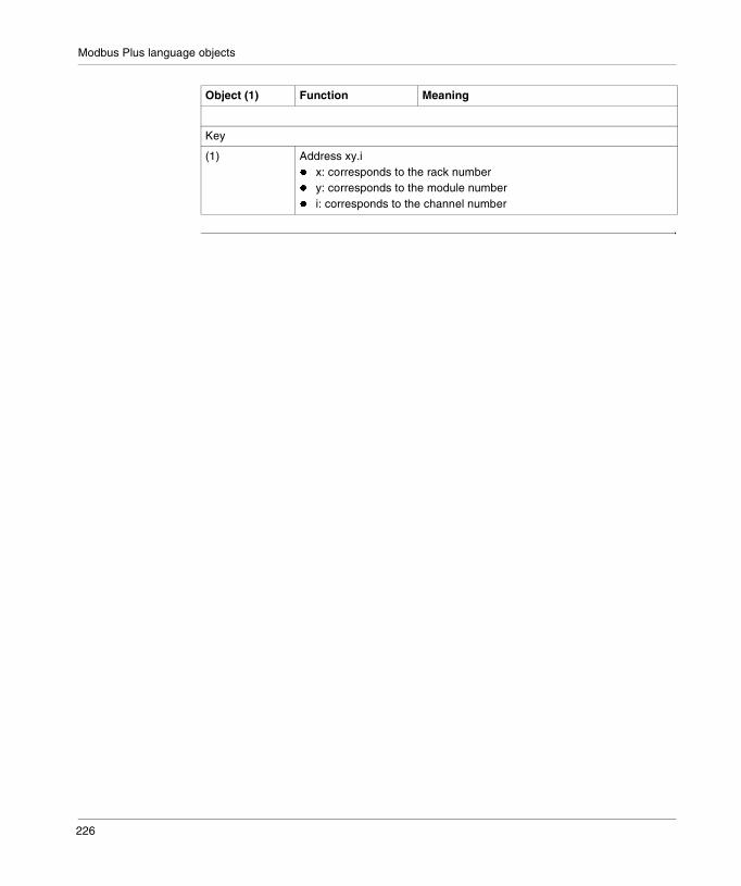
Modbus Plus language objects
Key
(1) Address xy.i� x: corresponds to the rack number� y: corresponds to the module number� i: corresponds to the channel number
Object (1) Function Meaning
226
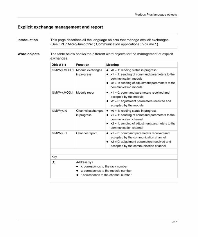
Modbus Plus language objects
Explicit exchange management and report
Introduction This page describes all the language objects that manage explicit exchanges (See : PL7 Micro/Junior/Pro ; Communication applications ; Volume 1).
Word objects The table below shows the different word objects for the management of explicit exchanges.
Object (1) Function Meaning
%MWxy.MOD.0 Module exchanges in progress
� x0 = 1: reading status in progress� x1 = 1: sending of command parameters to the
communication module� x2 = 1: sending of adjustment parameters to the
communication module
%MWxy.MOD.1 Module report � x1 = 0: command parameters received and accepted by the module
� x2 = 0: adjustment parameters received and accepted by the module
%MWxy.i.0 Channel exchanges in progress
� x0 = 1: reading status in progress� x1 = 1: sending of command parameters to the
communication channel� x2 = 1: sending of adjustment parameters to the
communication channel
%MWxy.i.1 Channel report � x1 = 0: command parameters received and accepted by the communication channel
� x2 = 0: adjustment parameters received and accepted by the communication channel
Key
(1) Address xy.i� x: corresponds to the rack number� y: corresponds to the module number� i: corresponds to the channel number
227
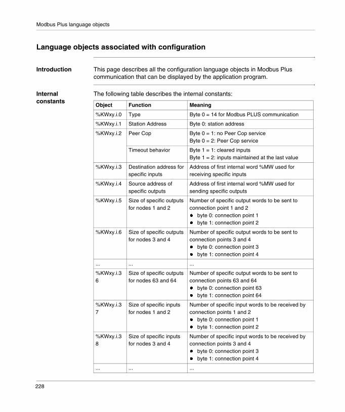
Modbus Plus language objects
Language objects associated with configuration
Introduction This page describes all the configuration language objects in Modbus Plus communication that can be displayed by the application program.
Internal constants
The following table describes the internal constants:
Object Function Meaning
%KWxy.i.0 Type Byte 0 = 14 for Modbus PLUS communication
%KWxy.i.1 Station Address Byte 0: station address
%KWxy.i.2 Peer Cop Byte 0 = 1: no Peer Cop serviceByte 0 = 2: Peer Cop service
Timeout behavior Byte 1 = 1: cleared inputsByte 1 = 2: inputs maintained at the last value
%KWxy.i.3 Destination address for specific inputs
Address of first internal word %MW used for receiving specific inputs
%KWxy.i.4 Source address of specific outputs
Address of first internal word %MW used for sending specific outputs
%KWxy.i.5 Size of specific outputs for nodes 1 and 2
Number of specific output words to be sent to connection point 1 and 2� byte 0: connection point 1� byte 1: connection point 2
%KWxy.i.6 Size of specific outputs for nodes 3 and 4
Number of specific output words to be sent to connection points 3 and 4� byte 0: connection point 3� byte 1: connection point 4
... ... ...
%KWxy.i.36
Size of specific outputs for nodes 63 and 64
Number of specific output words to be sent to connection points 63 and 64� byte 0: connection point 63� byte 1: connection point 64
%KWxy.i.37
Size of specific inputs for nodes 1 and 2
Number of specific input words to be received by connection points 1 and 2� byte 0: connection point 1� byte 1: connection point 2
%KWxy.i.38
Size of specific inputs for nodes 3 and 4
Number of specific input words to be received by connection points 3 and 4� byte 0: connection point 3� byte 1: connection point 4
... ... ...
228
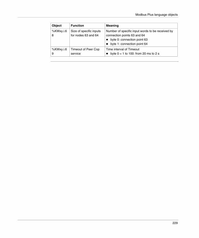
Modbus Plus language objects
%KWxy.i.68
Size of specific inputs for nodes 63 and 64
Number of specific input words to be received by connection points 63 and 64� byte 0: connection point 63� byte 1: connection point 64
%KWxy.i.69
Timeout of Peer Cop service
Time interval of Timeout� byte 0 = 1 to 100: from 20 ms to 2 s
Object Function Meaning
229

Modbus Plus language objects
230
IV
Communication via FIPIO busIntroduction
Subject of this part
This part introduces the principles of configuring and using FIPIO bus communication via PL7 software.
What’s in this Part?
This part contains the following chapters:
Chapter Chapter Name Page
18 Communication via FIPIO bus 233
19 Configuring Fipio communication 259
20 Programming Fipio communication 289
21 Debugging a Fipio communication 295
22 Fipio communication diagnostics 301
23 Language objects associated with Fipio communication 315
24 Fipio communication standard profiles 321
25 Fipio Agent 347
231

Communication via FIPIO
232
18
Communication via FIPIO busIntroduction
Subject of this Chapter
This Chapter introduces communication via the FIPIO bus and its services.
What’s in this Chapter?
This chapter contains the following sections:
Section Topic Page
18.1 Introduction to Fipio communication 234
18.2 Characteristics 239
233
General
18.1 Introduction to Fipio communication
Introduction
Aim of this Section
This Section provides a summary description of the Fipio bus and its associated services.
What’s in this Section?
This section contains the following topics:
Topic Page
Introduction 235
Addressing of language objects for modules remoted on the FIPIO bus 236
234

General
Introduction
Introduction Communication via FIPIO is part of Schneider Automation’s global WORLDFIP package.
FIPIO is a field bus used to delocalize the inputs/outputs of a PLC station and its industrial periphery to be as close as possible to the working part.
The FIPIO protocol uses producer/consumer exchanges (e.g.: common words) and the bus is managed via a bus arbiter.
Associated manuals
If you require further information you should consult the following manuals:
Title Description
FIPIO bus - Reference manual Detailed description of the FIPWAY bus and hardware installation
Micro PLCs - Installation manual Hardware installation
Premium TSX PLCs - Installation manual Hardware installation
������Refer to the separate documentation pertaining to each device connected to the FIPIO bus for details on their installation.
235

General
Addressing of language objects for modules remoted on the FIPIO bus
Presentation Addressing for the main bit and word objects for modules remoted on the FIPIO bus is geographical. This means that it depends on:� the connection point,� the module type (base or extension),� the channel number.
Illustration Addressing is defined as follows:
% I, Q, M, K X, W, D, F p.2.c m i r
Symbol Object type Format Module/channeladdress and connection point
Module number
Channelnumber
Rank\\
236

General
Syntax The table below shows the different elements which constitute addressing.
Family Element Values Meaning
Symbol % - -
Object type IQ
--
Image of the module’s physical input,Image of the module’s physical output,This information is exchanged automatically on each cycle of the task to which it is connected.
M - Internal variableThis read or write information is exchanged at the request of the application.
K - Internal constantThis configuration information is only accessible in read-only.
Format (size) X - BooleanFor boolean-type objects, the X may be omitted.
W 16 bits Single length.
D 32 bits Double length
F 32 bits Floating. The floating format used is that of IEEE standard 754-1985 (equivalent IEC 559).
Module/channel address and connection point
p 0 or 1 Number of the processor’s position in the rack.
2 - Channel number of the processor’s built-in FIPIO link.
c 1 to 127 Number of the connection point.
Module position m 0 or 1 0 : base module, 1: extension module.
Channel no. i 0 to 127 or MOD
MOD: channel reserved for management of the module and the parameters shared by all channels.
Position r 0 to 255 or ERR
ERR: indicates a module or channel fault.
237

General
Examples The table below gives some examples of object addressing.
Object Meaning
%MW\0.2.1\0.5.2 Position 2 status word for the image bit of input 5 of the remote input base module located at connection point 1 of the FIPIO bus.
%I\0.2.1\0.7 image bit of input 7 of the remote input base module located at connection point 1 of the FIPIO bus.
%Q\0.2.1\1.2 image bit of output 2 of the remote output extension module located at connection point 1 of the FIPIO bus.
%I\0.2.2\0.MOD.ERR Fault information for the Momentum module located at connection point 2 of the FIPIO bus.
%Q\1.2.3\0.0.ERR Fault information for channel 0 of module CCX17 located at connection point 3 of the FIPIO bus.
1 TBX DSS 16220 TBX DES 1622
0 170 AAI 030 00
TBX LEP 030
170 FNT 110 01
0
1
2
FIPIO manager TSX 57253
0 T CCX 17 20 FTSX FPP 0103
238
General
18.2 Characteristics
Introduction
Aim of this Section
This Section introduces the characteristics and constraints of using Fipio communication.
What’s in this Section?
This section contains the following topics:
Topic Page
Hardware compatibility relating to the bus manager 240
Software compatibility relating to the bus manager 241
Software compatibility: Network transparency 242
Software compatibility: communication with the exterior 244
Compatibility information relating to TBX devices 245
Compatibility information relating to Momentum devices 246
Compatibility information relating to the programming terminal 247
Compatibility information relating to other devices 248
FIPIO bus operating mode 250
Network cycle time: mono task application 252
Network cycle time: multitasking application 254
Example of calculating the network cycle times of a multitasking application 257
239
General
Hardware compatibility relating to the bus manager
General The binary flow of the bus is 1 Mbits/s and it can extend to a length of up to 15 Km, with four optical or electric repeaters (TSX FP ACC 6).
The FIPIO bus links up to Hirshmann optical transmitters, which allows medium redundancy architectures to be created.
Availability This type of communication is available via built-in links on Premium PLCs from version V3.0 onwards.
The PLCs with built-in FIPIO links are the following:� TSX type processors:
� TSX P57 153,� TSX P57 253, TSX P57 2823,� TSX P57 353� TSX P57 453, TSX P57 4823.
� PCX type processors:� PCX57353.
The bus manager can also be a PLC of the following type:� TSX 47-107 version 5.3 minimum,� S1000.
Capacity Processors with built-in FIPIO links are used to manage 128 connection points(TSX P57 153 = 64) on the bus (addresses 0 to 127).The bus manager is connected to address 0, and address 63 is reserved for the programming and diagnostics terminal.
These processors have a RAM memory for saving the configurations of devices connected to the bus. This memory has a maximum capacity of 94,320 bytes and 213,104 for (TSX P57 453/4823) processors.
240

General
Software compatibility relating to the bus manager
Explicit exchange limits
Processors with a built-in FIPIO link can simultaneously activate 24 explicit exchange functions.
An exchange request addressed to a FIPIO device can take several MAST task cycles. Thus, it is absolutely necessary to manage the exchange management parameter words for all exchanges of explicit variables including READ_STS %CH@channel and READ_STS %CH@MOD.
For example, if 24 functions are being processed simultaneously or if 25 functions are triggered in the same task cycle, the 25th, or any new function, will not be served and will terminate in error.
For a READ_STS exchange, if the twenty-fifth exchange is impossible, the report signals a communication fault in the word: %MW\p.2.c\m.v.2.
For WRITE_CMD, READ_PARAM, WRITE_PARAM, RESTORE_PARAM exchanges, the report signals a communication fault in the word %MW\p.2.c\m.v.1. A likely cause is a lack of system resources to provide the service.
Reminders The system word %SW155 contains the number of explicit exchanges in progress. Bit %SW116: x2 switches to 1 if the maximum number of simultaneous explicit exchanges is reached or exceeded.
X-TEL software When the bus manager is a series 7 PLC (TSX 47-107), the configuration of the bus and the manager is performed by the X-TEL software workbench, of version 6.0 or later.
241

General
Software compatibility: Network transparency
Introduction Exchanges from a remote station to the FIPIO bus or vice versa are possible under certain conditions.
Transparency restrictions
Inter-station communication with FIPIO is only available if the bus arbiter is a Premium PLC, of at least version V3.3.
Exchanges from a third-party device to a PLC connected as a FIPIO slave are only possible if the PLC is a Premium of V3.3 at least. Communication with a Micro PLC is not possible.
A FIPIO agent does not communicate with the exterior.
Only one programming terminal can be connected to the FIPIO bus. If it is present in the configuration, it must be connected to the default connection port (63).This programming terminal cannot be used to load the application onto the FIPIO bus arbiter.
242
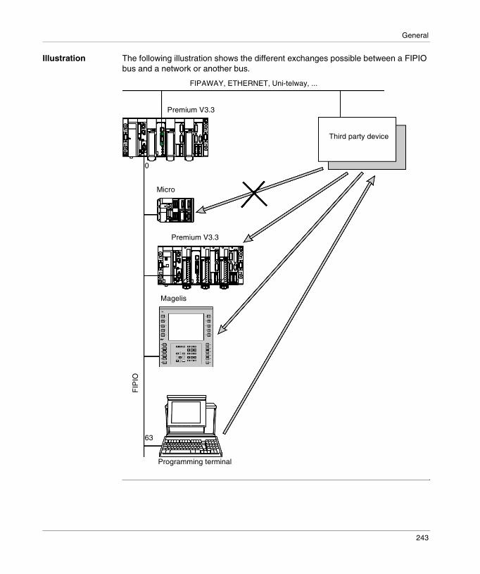
General
Illustration The following illustration shows the different exchanges possible between a FIPIO bus and a network or another bus.
FIPAWAY, ETHERNET, Uni-telway, ...
Premium V3.3
Premium V3.3
Micro
Magelis
Programming terminal
63
0
FIP
IOThird party device
243

General
Software compatibility: communication with the exterior
Introduction To communicate from a station connected to the FIPIO bus to an outside device, the transmitter station must address the master PLC and not the destination device (requests are not routed directly).
Example In the following example, an exchange from the FIPIO bus to the Uni-telway bus has to be performed. For a transfer in the opposite direction, the procedure is identical.
Step 1 The transmitter station, connected to connection port 6 on FIPIO, sends the request to the master PLC. The destination address is the master PLC address.WRITE_VAR (ADR#\6.1.0\SYS, %MW,0,10, %MW:10, %MW100:4)
The master PLC generates the report.
Step 2 When the master PLC application receives the request from the transmitter station, it directs it to the destination device in accordance with the Uni-telway protocol.WRITE_VAR (ADR#0.0.1, ’%MW’, 100, 10, %MW10:10, %MW40:4)
The report is sent to the master PLC.
������The master PLC application transfers these requests to the destination device.
Premium master, Serie 7
Uni-telway
Ad0 = 1Ad1 = 2Ad2 = 3
6
0
63
Step 1
Step 2
244

General
Compatibility information relating to TBX devices
Introduction The following compatibility information relates to:� the addressing supported by the different connectable devices,� the memory space that the devices take up in the configuration RAM.
Rules of use If a device linked to a connection port is modular, it must be homogeneous at an application-specific level. Discrete base and extension or analog base and extension (not a mixture of discrete and analog).
The device is only controlled by one PL7 task (FAST or MAST) (no assigning of channel groups of the same TBX to different tasks).
Addressing The FIPIO addressing depends on the type of device:
Maximum configuration
The number of modules of the same reference connected to the FIPIO bus in a configuration is limited. The values in the table below are expressed in bytes.
Types of device FIPIO addresses Comments
Compact TBXs 1...31 TBX C•
Sealed TBXs 1...62, 64...127 TBX E•
Modular TBXs 1...62, 64...127 TBX LEP 020, TBX LEP 030
TBX SAP 10 1...62, 64...127 AS-i gateway
Module Base Extension Maximum number of connection points
TSX P57 153
TSX P57 253/2823/353
TSX P57 453/4823
AES 200, ASS 400 1332 272 For 2 or 4 channels
62 70 125
AMS 620 1332 528 For 8 channels
59 59 126
For 10 or 12 channels
50 50 114
CEP 1622, CSP 1622, CSP 1625
1152 - 31 31 31
DES •••, DMS •••, DSS ••• 1152 144 62 81 126
SAP 10 1088 - 52 52 117
245
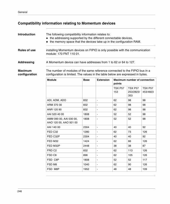
General
Compatibility information relating to Momentum devices
Introduction The following compatibility information relates to:� the addressing supported by the different connectable devices,� the memory space that the devices take up in the configuration RAM.
Rules of use installing Momentum devices on FIPIO is only possible with the communication module: 170 FNT 110 01.
Addressing A Momentum device can have addresses from 1 to 62 or 64 to 127.
Maximum configuration
The number of modules of the same reference connected to the FIPIO bus in a configuration is limited. The values in the table below are expressed in bytes.
Module Base Extension Maximum number of connection points
TSX P57 153
TSX P57 253/2823/353
TSX P57 453/4823
ADI, ADM, ADO 832 - 62 98 98
ARM 370 30 832 - 62 98 98
ANR 120 90 832 - 62 98 98
AAI 520 40 00 1808 - 52 52 98
AMM 090 00, AAI 030 00, AAO 120 00, AAO 921 00
1808 - 52 52 98
AAI 140 00 2304 - 40 40 92
FED C32 1280 - 62 73 126
FED C32P 2304 - 40 40 92
FED M32 1424 - 62 66 126
FED M32P 2448 - 38 38 87
FRD C2 832 - 62 113 126
FSD C8 896 - 62 105 126
FSD C8P 1808 - 52 52 117
FSD M8 1040 - 62 90 126
FSD M8P 1952 - 48 48 109
246
General
Compatibility information relating to the programming terminal
Introduction The following compatibility information relates to:� the addressing supported by the different connectable devices,� the memory space that the devices take up in the configuration RAM.
Rules of use A programming terminal fitted with the TSX FPC 10 card or the PCMCIA cardTSX FPP 20 must be connected to the FIPIO address 63.
PL7 operates in connected mode with the FIPIO manager PLC.If the manager PLC has an application in which one or several agent devices are configured:� PL7 communicates with the Micro/Premium FIPIO agent PLCs.� MMI 17 communicates with the CCX-17.
It is not possible to download a PL7 application to the manager from a programming terminal. However, it is possible to download a PL7 application to a FIPIO agent PLC.
247
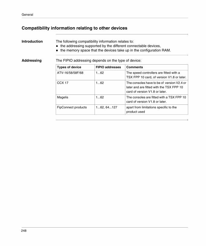
General
Compatibility information relating to other devices
Introduction The following compatibility information relates to:� the addressing supported by the different connectable devices,� the memory space that the devices take up in the configuration RAM.
Addressing The FIPIO addressing depends on the type of device:
Types of device FIPIO addresses Comments
ATV-16/58/58F/68 1...62 The speed controllers are fitted with aTSX FPP 10 card, of version V1.8 or later.
CCX 17 1...62 The consoles have to be of version V2.4 or later and are fitted with the TSX FPP 10 card of version V1.8 or later.
Magelis 1...62 The consoles are fitted with a TSX FPP 10 card of version V1.8 or later.
FipConnect products 1...62, 64...127 apart from limitations specific to the product used
248
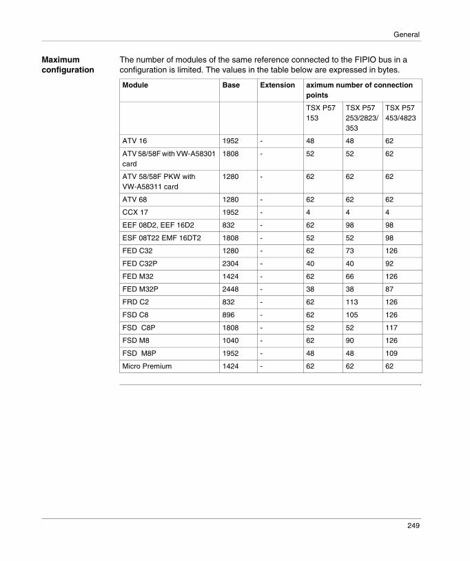
General
Maximum configuration
The number of modules of the same reference connected to the FIPIO bus in a configuration is limited. The values in the table below are expressed in bytes.
Module Base Extension aximum number of connection points
TSX P57 153
TSX P57 253/2823/353
TSX P57 453/4823
ATV 16 1952 - 48 48 62
ATV 58/58F with VW-A58301 card
1808 - 52 52 62
ATV 58/58F PKW with VW-A58311 card
1280 - 62 62 62
ATV 68 1280 - 62 62 62
CCX 17 1952 - 4 4 4
EEF 08D2, EEF 16D2 832 - 62 98 98
ESF 08T22 EMF 16DT2 1808 - 52 52 98
FED C32 1280 - 62 73 126
FED C32P 2304 - 40 40 92
FED M32 1424 - 62 66 126
FED M32P 2448 - 38 38 87
FRD C2 832 - 62 113 126
FSD C8 896 - 62 105 126
FSD C8P 1808 - 52 52 117
FSD M8 1040 - 62 90 126
FSD M8P 1952 - 48 48 109
Micro Premium 1424 - 62 62 62
249
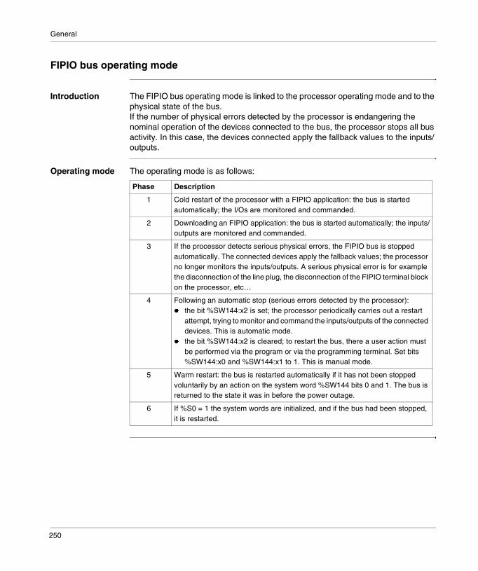
General
FIPIO bus operating mode
Introduction The FIPIO bus operating mode is linked to the processor operating mode and to the physical state of the bus.If the number of physical errors detected by the processor is endangering the nominal operation of the devices connected to the bus, the processor stops all bus activity. In this case, the devices connected apply the fallback values to the inputs/outputs.
Operating mode The operating mode is as follows:
Phase Description
1 Cold restart of the processor with a FIPIO application: the bus is started automatically; the I/Os are monitored and commanded.
2 Downloading an FIPIO application: the bus is started automatically; the inputs/outputs are monitored and commanded.
3 If the processor detects serious physical errors, the FIPIO bus is stopped automatically. The connected devices apply the fallback values; the processor no longer monitors the inputs/outputs. A serious physical error is for example the disconnection of the line plug, the disconnection of the FIPIO terminal block on the processor, etc…
4 Following an automatic stop (serious errors detected by the processor):� the bit %SW144:x2 is set; the processor periodically carries out a restart
attempt, trying to monitor and command the inputs/outputs of the connected devices. This is automatic mode.
� the bit %SW144:x2 is cleared; to restart the bus, there a user action must be performed via the program or via the programming terminal. Set bits %SW144:x0 and %SW144:x1 to 1. This is manual mode.
5 Warm restart: the bus is restarted automatically if it has not been stopped voluntarily by an action on the system word %SW144 bits 0 and 1. The bus is returned to the state it was in before the power outage.
6 If %S0 = 1 the system words are initialized, and if the bus had been stopped, it is restarted.
250
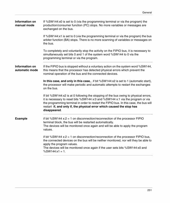
General
Information on manual mode
If %SW144:x0 is set to 0 (via the programming terminal or via the program) the production/consumer function (PC) stops. No more variables or messages are exchanged on the bus.
If %SW144:x1 is set to 0 (via the programming terminal or via the program) the bus arbiter function (BA) stops. There is no more scanning of variables or messages on the bus.
To completely and voluntarily stop the activity on the FIPIO bus, it is necessary to simultaneously set bits 0 and 1 of the system word %SW144 to 0 via the programming terminal or via the program.
Information on automatic mode
If the FIPIO bus is stopped without a voluntary action on the system word %SW144, this means that the processor has detected physical errors which prevent the nominal operation of the bus and the connected devices.
In this case, and only in this case, , if bit %SW144:x2 is set to 1 (automatic start), the processor will make periodic and automatic attempts to restart the exchanges on the bus.
If bit %SW144:x2 is at 0 following the stopping of the bus owing to physical errors, it is necessary to reset bits %SW144 x:0 and %SW144 x:1 via the program or via the programming terminal in order to restart the FIPIO bus. In this case, the bus will restart if, and only if, the physical error which caused the stop has disappeared.
Example if bit %SW144 x:2 = 1 on disconnection/reconnection of the processor FIPIO terminal block, the bus will be restarted automatically. The devices will be monitored once again and will be able to apply the program values.
if bit %SW144 x:2 = 1 on disconnection/reconnection of the processor FIPIO bus, the connected devices on the bus will be neither monitored, nor will they be able to apply the program values. The devices will be monitored once again if the user sets bits %SW144:x0 and %SW144:x1 = 1.
251

General
Network cycle time: mono task application
Introduction The network cycle time for a mono task application is calculated for the following configuration:� the length of the bus is 1 Km,� the values corresponding to the reversal and silence times and the bandwidths
are default values (automatic mode).
Calculation of the network cycle time
For an application which has all the devices configured in the same task, the value of the network cycle time of the task, in milliseconds, is obtained, for information purposes only, by the following formula:
Value of coefficient K
Coefficient K will be defined as follows:
TCR_TASK= 1,45 + Σ(K x number of equipments of the same family)
Coefficient K Family Device
0,5 TBX Discrete
0,9 TBX Analog
0,4 Momentum Discrete
0,6 Momentum Analog
0,6 ATV-16 All
0,6 ATV-58 All
0,6 CCX 17 All
1,5 CCX 17-32 All
1,5 TSX 37/57 All
0,6 AS-i gateway TSX SAP 10
1,5 Magelis All
0,4 STD_P FRD
0,6 STD_P FSP
1,5 STD_P FED
252
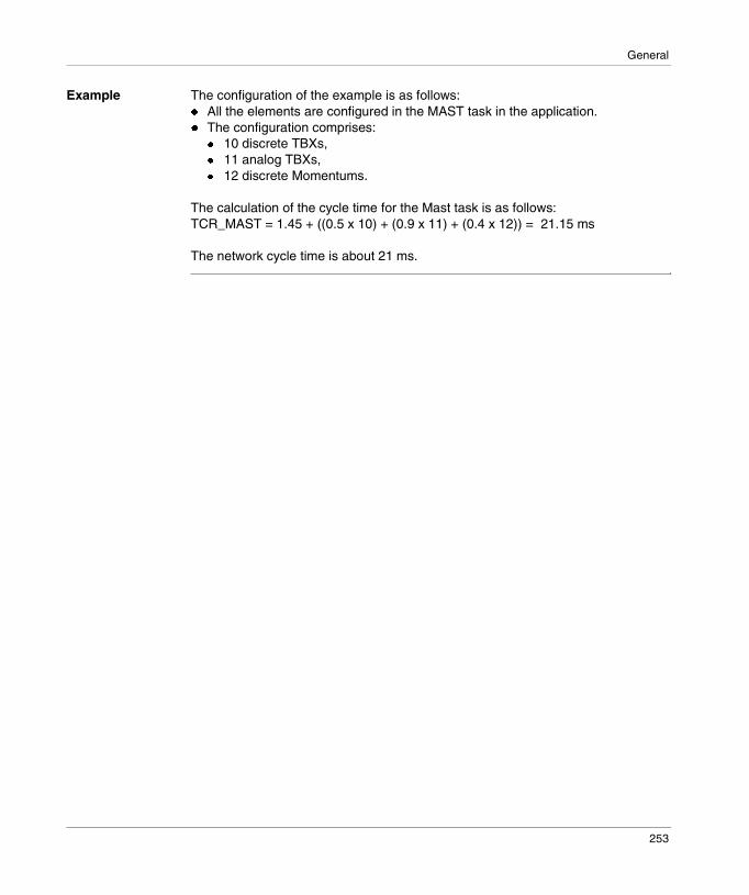
General
Example The configuration of the example is as follows:� All the elements are configured in the MAST task in the application.� The configuration comprises:
� 10 discrete TBXs,� 11 analog TBXs,� 12 discrete Momentums.
The calculation of the cycle time for the Mast task is as follows:TCR_MAST = 1.45 + ((0.5 x 10) + (0.9 x 11) + (0.4 x 12)) = 21.15 ms
The network cycle time is about 21 ms.
253
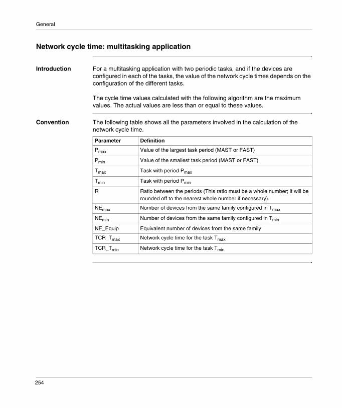
General
Network cycle time: multitasking application
Introduction For a multitasking application with two periodic tasks, and if the devices are configured in each of the tasks, the value of the network cycle times depends on the configuration of the different tasks.
The cycle time values calculated with the following algorithm are the maximum values. The actual values are less than or equal to these values.
Convention The following table shows all the parameters involved in the calculation of the network cycle time.
Parameter Definition
Pmax Value of the largest task period (MAST or FAST)
Pmin Value of the smallest task period (MAST or FAST)
Tmax Task with period Pmax
Tmin Task with period Pmin
R Ratio between the periods (This ratio must be a whole number; it will be rounded off to the nearest whole number if necessary).
NEmax Number of devices from the same family configured in Tmax
NEmin Number of devices from the same family configured in Tmin
NE_Equip Equivalent number of devices from the same family
TCR_Tmax Network cycle time for the task Tmax
TCR_Tmin Network cycle time for the task Tmin
254
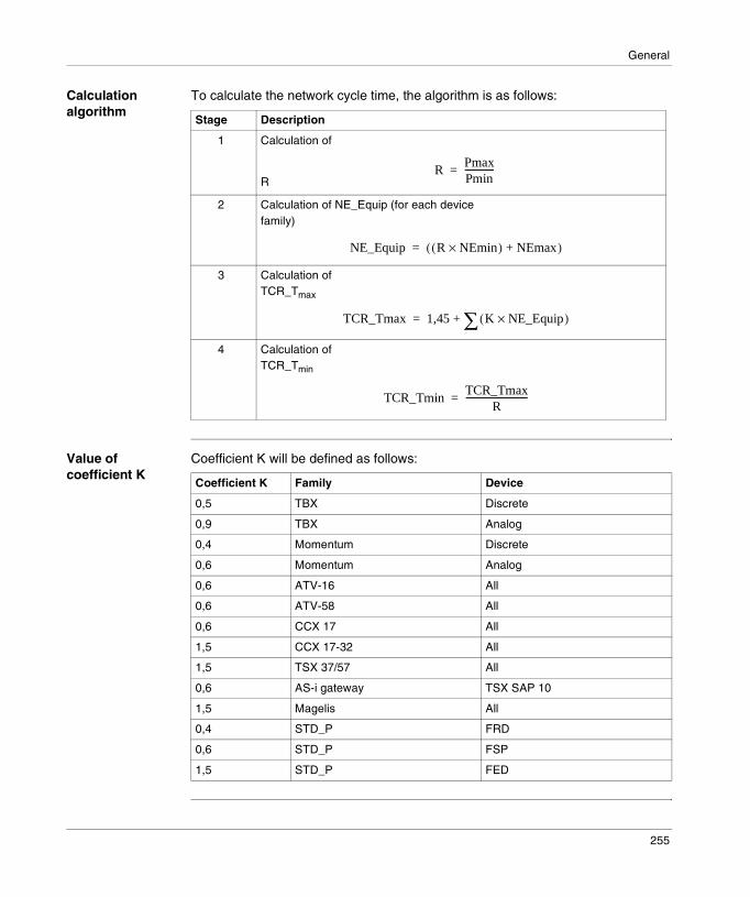
General
Calculation algorithm
To calculate the network cycle time, the algorithm is as follows:
Value of coefficient K
Coefficient K will be defined as follows:
Stage Description
1 Calculation of
R
2 Calculation of NE_Equip (for each device family)
3 Calculation of TCR_Tmax
4 Calculation of TCR_Tmin
RPmaxPmin-------------=
NE_Equip R NEmin×( ) NEmax+( )=
TCR_Tmax 1,45 K NE_Equip×( )∑+=
TCR_TminTCR_Tmax
R----------------------------=
Coefficient K Family Device
0,5 TBX Discrete
0,9 TBX Analog
0,4 Momentum Discrete
0,6 Momentum Analog
0,6 ATV-16 All
0,6 ATV-58 All
0,6 CCX 17 All
1,5 CCX 17-32 All
1,5 TSX 37/57 All
0,6 AS-i gateway TSX SAP 10
1,5 Magelis All
0,4 STD_P FRD
0,6 STD_P FSP
1,5 STD_P FED
255

General
Interpretation of the results
To refresh the inputs/outputs on the bus, the following constraints are imposed:� For the periodic tasks in controlled mode, the network cycle time of the task must
be less than the task period.� For the periodic tasks in free mode, the network cycle time of the task must be
less than the task watchdog.
256
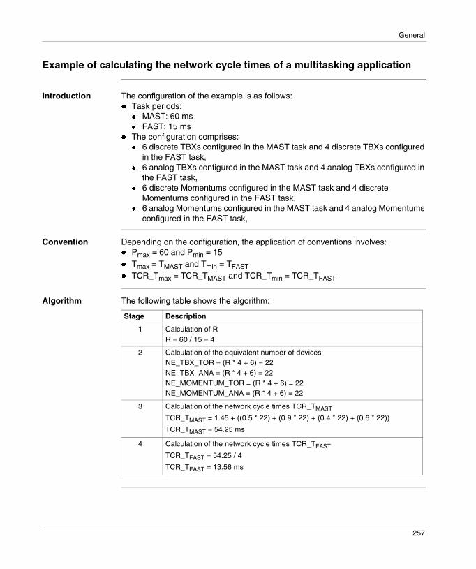
General
Example of calculating the network cycle times of a multitasking application
Introduction The configuration of the example is as follows:� Task periods:
� MAST: 60 ms� FAST: 15 ms
� The configuration comprises:� 6 discrete TBXs configured in the MAST task and 4 discrete TBXs configured
in the FAST task,� 6 analog TBXs configured in the MAST task and 4 analog TBXs configured in
the FAST task,� 6 discrete Momentums configured in the MAST task and 4 discrete
Momentums configured in the FAST task,� 6 analog Momentums configured in the MAST task and 4 analog Momentums
configured in the FAST task,
Convention Depending on the configuration, the application of conventions involves:� Pmax = 60 and Pmin = 15� Tmax = TMAST and Tmin = TFAST
� TCR_Tmax = TCR_TMAST and TCR_Tmin = TCR_TFAST
Algorithm The following table shows the algorithm:
Stage Description
1 Calculation of RR = 60 / 15 = 4
2 Calculation of the equivalent number of devicesNE_TBX_TOR = (R * 4 + 6) = 22NE_TBX_ANA = (R * 4 + 6) = 22NE_MOMENTUM_TOR = (R * 4 + 6) = 22NE_MOMENTUM_ANA = (R * 4 + 6) = 22
3 Calculation of the network cycle times TCR_TMAST
TCR_TMAST = 1.45 + ((0.5 * 22) + (0.9 * 22) + (0.4 * 22) + (0.6 * 22))
TCR_TMAST = 54.25 ms
4 Calculation of the network cycle times TCR_TFAST
TCR_TFAST = 54.25 / 4
TCR_TFAST = 13.56 ms
257

General
Conclusions The network cycle times of each equal:� TCR_TMAST = 55 ms,� TCR_TFAST = 14 ms.The time period for MAST and FAST tasks are sufficient to refresh the inputs/outputs.
258

19
Configuring Fipio communicationIntroduction
Subject of this Chapter
This chapter describes the Configuration process during set-up of Fipio communication.
What’s in this Chapter?
This chapter contains the following sections:
Section Topic Page
19.1 General information on configuration 260
19.2 Fipio bus configuration 261
19.3 Configuration of devices on the Fipio bus 275
19.4 Input/output management by the PL7 tasks 280
19.5 Confirmation of the Fipio bus configuration 284
259
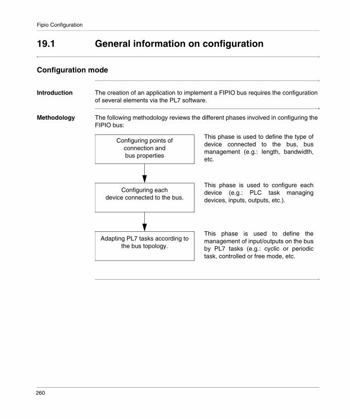
Fipio Configuration
19.1 General information on configuration
Configuration mode
Introduction The creation of an application to implement a FIPIO bus requires the configuration of several elements via the PL7 software.
Methodology The following methodology reviews the different phases involved in configuring the FIPIO bus:
Configuring points of connection and bus properties
Configuring each device connected to the bus.
Adapting PL7 tasks according tothe bus topology.
This phase is used to define the type ofdevice connected to the bus, busmanagement (e.g.: length, bandwidth,etc.
This phase is used to configure eachdevice (e.g.: PLC task managingdevices, inputs, outputs, etc.).
This phase is used to define themanagement of input/outputs on the busby PL7 tasks (e.g.: cyclic or periodictask, controlled or free mode, etc.
260
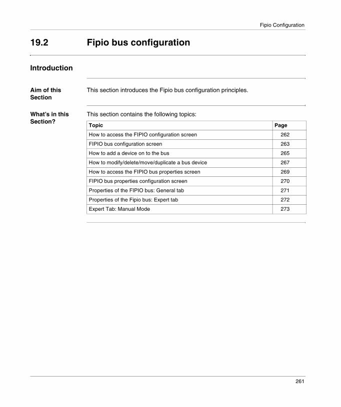
Fipio Configuration
19.2 Fipio bus configuration
Introduction
Aim of this Section
This section introduces the Fipio bus configuration principles.
What’s in this Section?
This section contains the following topics:
Topic Page
How to access the FIPIO configuration screen 262
FIPIO bus configuration screen 263
How to add a device on to the bus 265
How to modify/delete/move/duplicate a bus device 267
How to access the FIPIO bus properties screen 269
FIPIO bus properties configuration screen 270
Properties of the FIPIO bus: General tab 271
Properties of the Fipio bus: Expert tab 272
Expert Tab: Manual Mode 273
261

Fipio Configuration
How to access the FIPIO configuration screen
Introduction This operation describes how to access the configuration via the the Premium PLCs provided with a built-in link.
How to access the link
The following table shows the procedure for accessing the FIPIO link:
Step Action
1 Access the hardware configuration screen
2 Double click on the FIPIO connector.
262
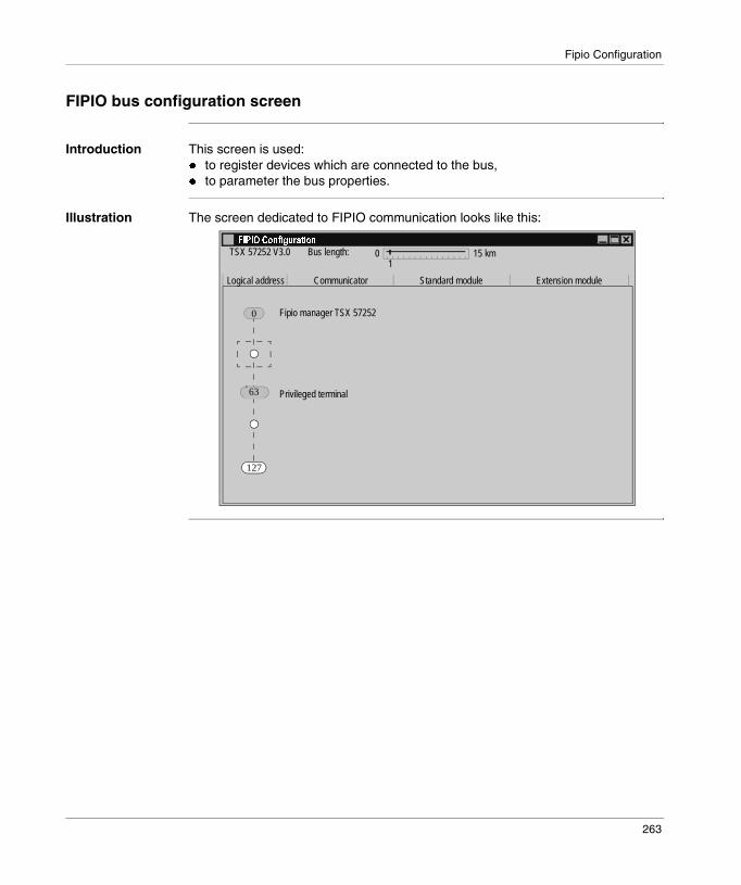
Fipio Configuration
FIPIO bus configuration screen
Introduction This screen is used:� to register devices which are connected to the bus,� to parameter the bus properties.
Illustration The screen dedicated to FIPIO communication looks like this:
+� ����� �!�������
0 15 km1
Logical address Communicator Standard module Extension module
Bus length:TSX 57252 V3.0
0
63
127
Fipio manager TSX 57252
Privileged terminal
263

Fipio Configuration
Elements and functions
This table describes the different areas that make up the configuration screen:
Grayed out rectangles on the bus indicate the two reserved addresses:� 0 for the bus manager,� 63 for the privileged terminal.
The available connection points are indicated by a small circle and dotted lines.
Zone Function
Bus length This cursor is used to adjust the bus length. The default value is 1 Km.
Logical address This zone defines the address for each device.
Communicator This zone specifies the type of device which enables communication between the manager and the standard device.Where the standard device has no need for a communicator, this zone is empty.
Standard module This zone specifies the standard device connected to the bus.
Extension module This zone gives information on whether an extension is associated to the standard device.
264

Fipio Configuration
How to add a device on to the bus
Procedure This operation is used to logically add a device connected to the FIPIO bus.
Step Action
1 Access the FIPIO configuration screen.
2 Double click on the logic address of the connection point at the place where the module must be connected (available addresses ranging from 1 to 62 and from 64 to 127, addresses 0 and 63 being reserved by the system).Result: the Add/Modify a device screen appears.
3 Enter the connection point number which corresponds to the address.By default, the PL7 software offers the first consecutive address which is free
4 Add a comment to the device connected to the connection point.This field has a maximum length of 80 characters and is optional.
5 In the Family field, select the type of equipment to be connected to the bus.
6 Select the standard module and/or the extension module.
7 In the Communicator field, select the type of element enabling communication on the FIPIO bus.For certain types of device, this window does not appear.
OK
Cancel
Connection point
Families
Connection point numberComment
Standard module
Communicator
TBX LEP 020 TBX7 MOD.COM.FIP 24/48VTBX LEP 030 TBX7 MOD.COM.FIP TOR+ANA
1
##,"�#� -���#�.�$�
TBX DMS 1625
ATV-16 1.0ATV-58 1.0CCX-17 1.0CCX17-32 1.0MAGELIS 1.0MOMENTUM 1.0PASSERELLE 1.0SIMULATION 1.0STD_P 1.0TBX 1.0TSX 1.0
TBX DES 1633 TBX7 EMB. 16E 48VCCTBX DES 16C22 TBX7 EMB. 16E CF 24VCCTBX DES 16F22 TBX7 EMB. 16E RAP 24VCCTBX DES 16S04 TBX7 EMB. 16E 120 VCATBX DMS 1025 TBX7 EMB. 8E/2SR 24VCCTBX DMS 1625 TBX7 EMB. 8E/8SR 24VCCTBX DMS 16C22 TBX7 EMB. 8E+8SS 0,5A CFTBX DMS 16C222 TBX7 EMB. 8E+8SS 2A CFTBX DMS 16P22 TBX7 EMB. 8E+8E/S 0,5A
Extension module
265

Fipio Configuration
8 Confirm with Ok.Result: the module is registered.
Step Action
+� ����� �!�������
1 TBX DES 16220 TBX DSS 1622
0 TBX AES 400
TBX LEP 020
TBX LEP 030
0 15 km5
Logical address Communicator Standard module Extension module
Bus length:TSX 57252 V3.0
0
1
2
Fipio managerTSX 57252
266
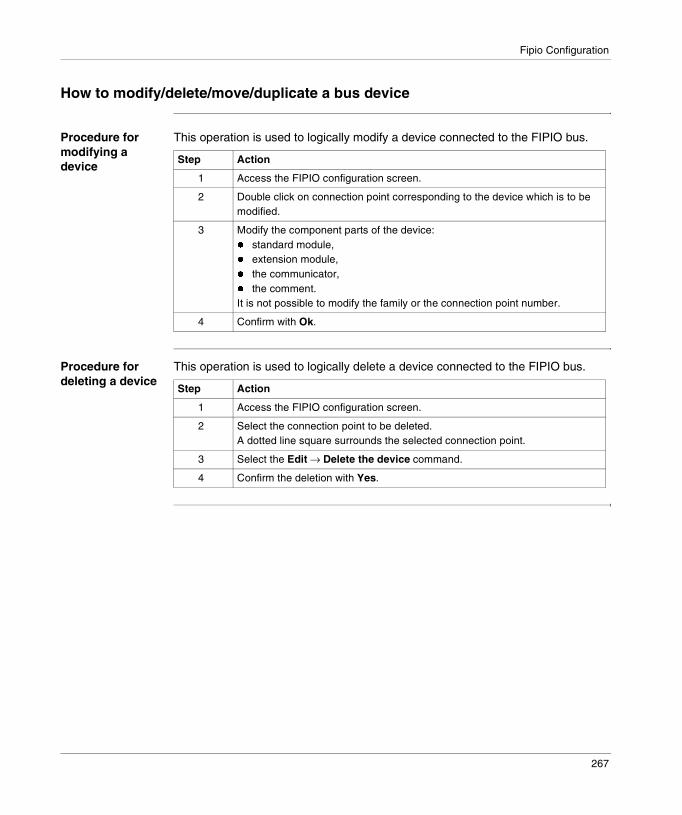
Fipio Configuration
How to modify/delete/move/duplicate a bus device
Procedure for modifying a device
This operation is used to logically modify a device connected to the FIPIO bus.
Procedure for deleting a device
This operation is used to logically delete a device connected to the FIPIO bus.
Step Action
1 Access the FIPIO configuration screen.
2 Double click on connection point corresponding to the device which is to be modified.
3 Modify the component parts of the device:� standard module,� extension module,� the communicator,� the comment.It is not possible to modify the family or the connection point number.
4 Confirm with Ok.
Step Action
1 Access the FIPIO configuration screen.
2 Select the connection point to be deleted.A dotted line square surrounds the selected connection point.
3 Select the Edit → Delete the device command.
4 Confirm the deletion with Yes.
267
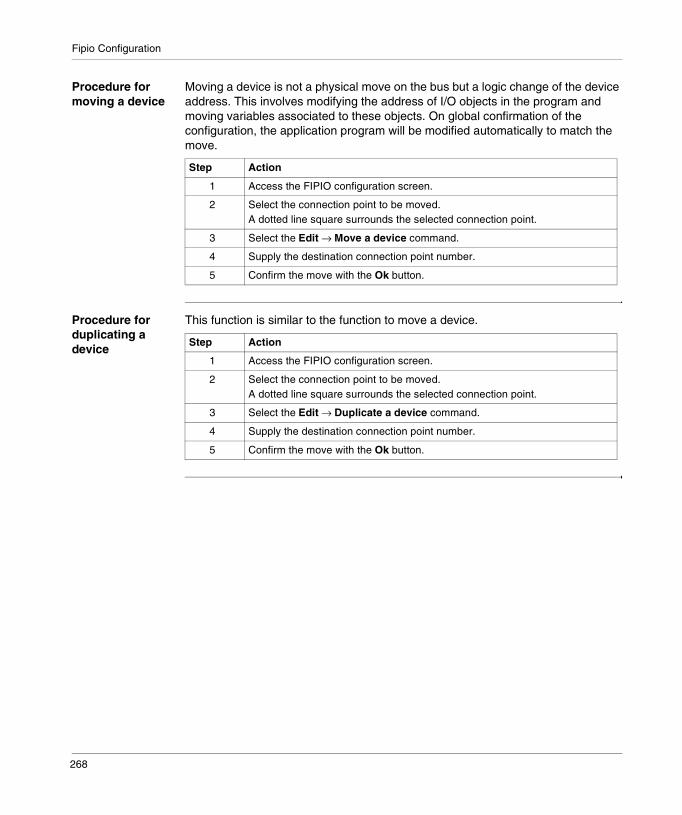
Fipio Configuration
Procedure for moving a device
Moving a device is not a physical move on the bus but a logic change of the device address. This involves modifying the address of I/O objects in the program and moving variables associated to these objects. On global confirmation of the configuration, the application program will be modified automatically to match the move.
Procedure for duplicating a device
This function is similar to the function to move a device.
Step Action
1 Access the FIPIO configuration screen.
2 Select the connection point to be moved.A dotted line square surrounds the selected connection point.
3 Select the Edit → Move a device command.
4 Supply the destination connection point number.
5 Confirm the move with the Ok button.
Step Action
1 Access the FIPIO configuration screen.
2 Select the connection point to be moved.A dotted line square surrounds the selected connection point.
3 Select the Edit → Duplicate a device command.
4 Supply the destination connection point number.
5 Confirm the move with the Ok button.
268
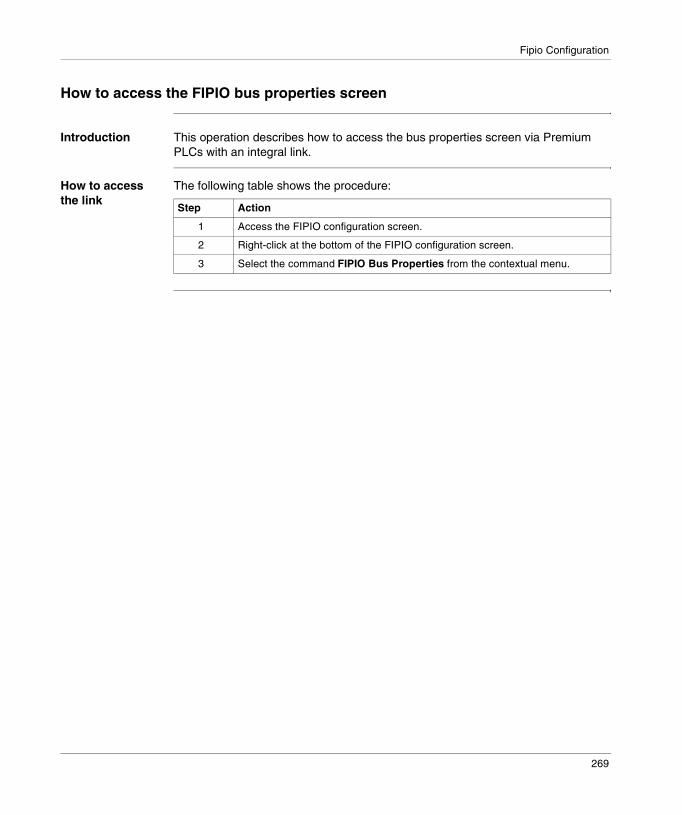
Fipio Configuration
How to access the FIPIO bus properties screen
Introduction This operation describes how to access the bus properties screen via Premium PLCs with an integral link.
How to access the link
The following table shows the procedure:
Step Action
1 Access the FIPIO configuration screen.
2 Right-click at the bottom of the FIPIO configuration screen.
3 Select the command FIPIO Bus Properties from the contextual menu.
269
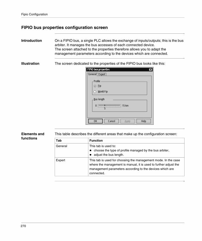
Fipio Configuration
FIPIO bus properties configuration screen
Introduction On a FIPIO bus, a single PLC allows the exchange of inputs/outputs; this is the bus arbiter. It manages the bus accesses of each connected device.The screen attached to the properties therefore allows you to adapt the management parameters according to the devices which are connected.
Illustration The screen dedicated to the properties of the FIPIO bus looks like this:
Elements and functions
This table describes the different areas that make up the configuration screen:
+� ���/���*��*������
0 15 km5
Fip
World Fip
Profile
Bus length
General Expert
OK Cancel Apply Help
Tab Function
General This tab is used to:� choose the type of profile managed by the bus arbiter,� adjust the bus length.
Expert This tab is used for choosing the management mode. In the case where the management is manual, it is used to further adjust the management parameters according to the devices which are connected.
270

Fipio Configuration
Properties of the FIPIO bus: General tab
Introduction With this tab, you can access two types of information: � the profile, � the bus length.
The profile The profile is chosen according to the devices which are connected to the FIPIO bus. It can be in either of two versions:� FIP:
� This profile is chosen by default.� It is compatible with all the devices of Schneider and partners.
� WorldFip:� The selection of this mode allows you to operate the FIPIO bus in accordance
with the EN 50170 standard.
The bus length With this cursor you can increase or decrease the bus length. The default value is 1 Km and the adjustment increment is 1 Km.
This length must be adjusted because it is taken into account in the calculation of the propagation time for the signals on the bus and consequently in the calculation of the network cycle times.
������The WorldFip profile mode can be used with the following restrictions:� no TSX FP ACC6 or TSX FP ACC8 repeaters,� use of TBX LEP 020 version 1.4 minimum and TBX LEP 030 version 1.2
minimum,� use of the PCMCIA TSX FPP 10 card, version 1.8 minimum.
������At each modification of the length of the FIPIO bus, all the connected devices must be powered off, then on after the new application has been downloaded (in the PLC).
271

Fipio Configuration
Properties of the Fipio bus: Expert tab
Introduction With this tab, you have access to the management mode concerning the calculation of: � reversal and silence time,� bandwidths.
The automatic mode
The reversal and silence times and the bandwidths cannot be modified. They are calculated according to the bus parameters and device configuration data.
The manual mode
This mode is used to enter the reversal and silence times and the bandwidths.It is mainly reserved for specific applications requiring these values to be modified (example: use of Hirschmann transmittors).
������At each modification of the parameters below, all the connected devices must be powered off, then on after the new application has been downloaded (in the PLC).
������This mode is advocated.
������
No monitoring is carried out in manual mode. Modifying these parameters can cause the device connected to the bus not to work.
$�� %������&� ����"���#����%������������% �������'%�(�����)%�#�������!�*
272

Fipio Configuration
Expert Tab: Manual Mode
At a Glance By selecting the manual mode, you have access to the following information: � The reversal and silence times,� The aperiodic bandwidths.Illustration:
0���*��*������
Mode
Bandwidth
Automatic
Manual
General Expert
CancelOK Help
Aperiodic variables (kbits/s):
Message handling (kbits/s):
Silence time T0 (µs):
Slot time TR (µs):
255
30
5
20
273
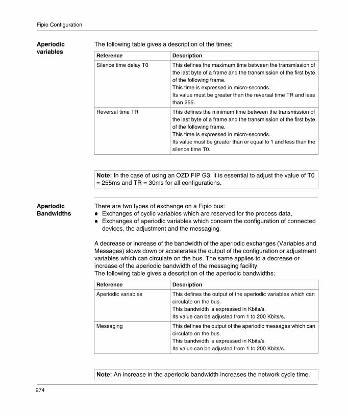
Fipio Configuration
Aperiodic variables
The following table gives a description of the times:
Aperiodic Bandwidths
There are two types of exchange on a Fipio bus: � Exchanges of cyclic variables which are reserved for the process data,� Exchanges of aperiodic variables which concern the configuration of connected
devices, the adjustment and the messaging.
A decrease or increase of the bandwidth of the aperiodic exchanges (Variables and Messages) slows down or accelerates the output of the configuration or adjustment variables which can circulate on the bus. The same applies to a decrease or increase of the aperiodic bandwidth of the messaging facility.The following table gives a description of the aperiodic bandwidths:
Reference Description
Silence time delay T0 This defines the maximum time between the transmission of the last byte of a frame and the transmission of the first byte of the following frame.This time is expressed in micro-seconds.Its value must be greater than the reversal time TR and less than 255.
Reversal time TR This defines the minimum time between the transmission of the last byte of a frame and the transmission of the first byte of the following frame.This time is expressed in micro-seconds.Its value must be greater than or equal to 1 and less than the silence time T0.
������In the case of using an OZD FIP G3, it is essential to adjust the value of T0 = 255ms and TR = 30ms for all configurations.
Reference Description
Aperiodic variables This defines the output of the aperiodic variables which can circulate on the bus.This bandwidth is expressed in Kbits/s.Its value can be adjusted from 1 to 200 Kbits/s.
Messaging This defines the output of the aperiodic messages which can circulate on the bus.This bandwidth is expressed in Kbits/s.Its value can be adjusted from 1 to 200 Kbits/s.
������An increase in the aperiodic bandwidth increases the network cycle time.
274

Fipio Configuration
19.3 Configuration of devices on the Fipio bus
Introduction
Aim of this Section
This section introduces the configuration principles for Fipio bus devices.
What’s in this Section?
This section contains the following topics:
Topic Page
How to access the FIPIO configuration screen 276
Configuration screen of a FIPIO device 277
How to access the different parameters according to device type 279
275

Fipio Configuration
How to access the FIPIO configuration screen
Introduction When a device has been registered, it is possible to access its configuration as in the case of a rack module.
This screen is used to select the task which exchanges the inputs/outputs: FAST or MAST, to modify the configuration or adjustment parameters specific to the module.
How to access the link
The following table shows the procedure for accessing the configuration of a device on FIPIO:
Step Action
1 Access the FIPIO configuration screen
2 Double click on the standard module to be configured.
276

Fipio Configuration
Configuration screen of a FIPIO device
Introduction This screen, split into several areas, is used to register the communication channel and to configure the parameters of the device selected for a FIPIO communication.
Illustration The screen looks like this:
1
2
3
4
+�1�"2� ���+� ���2�����"�13%����
Local configurationMAST
Configuration Designation: EQP STD MOD 8MP
Default configuration Base
Channel
Decimal
Parameters Symbol Value%KW\0.2.18\0.0.0 16#8040%KW\0.2.18\0.0.1 16#0%KW\0.2.18\0.0.2 0%KW\0.2.18\0.0.3 0%KW\0.2.18\0.0.4 0%KW\0.2.18\0.0.5 16#4%KW\0.2.18\0.0.6 0%KW\0.2.18\0.0.7 0
Task:
277

Fipio Configuration
Elements and functions
This table describes the different areas that make up the configuration screen:
Address Zone Description
1 Title bar This zone defines the module reference and its physical position in the module.
2 Module This zone is used to input information with the aid of dropdown lists:� parameter type:
� the Configuration mode,� the Adjustment mode (which can be accessed by certain device types),� the Debugging mode (can only be accessed in online mode).
� channel type (inputs or outputs) when the designated device has inputs and outputs.
3 Communication channel This zone is used to assign devices to either the MAST task or the FAST task, with the aid of a dropdown list.Some device types have access to a Local configuration check box. If the box is checked off, the channel parameters can not be accessed.
4 Channel parameters This zone is used for device parametering. According to certain device types, this zone can not be accessed.
������For further information on configuration parameters, adjustment parameters and debugging parameters, refer to the documentation specific to each device.
278

Fipio Configuration
How to access the different parameters according to device type
How to access the inputs/outputs
The following procedure provides information on how to access the input or output parameters of a module. It is enabled in both offline and online mode.
How to adjust the configuration parameters
The following procedure describes how to modify the adjustment parameters of a module. It is enabled in both offline and online mode.
How to assign a module to a PL7 task
The following procedure describes how to assign a module to a PL7 task. It is only enabled in offline mode.
Step Action
1 Access the configuration screen of a FIPIO device.
2 Select input part or output part from the module zone’s dropdown list.
Step Action
1 Access the configuration screen of a FIPIO device.
2 Select adjustment mode from the module zone’s dropdown list.
3 Select the cell relating to the entry parameter.
4 Enter the parameter.
5 Enable by clicking on Input.
6 Enable the assignment.
Step Action
1 Access the configuration screen of a FIPIO device.
2 Select MAST → or FASTTask from the dropdown list.
3 Enable the assignment.
279
Fipio Configuration
19.4 Input/output management by the PL7 tasks
Introduction
Aim of this Section
This Section introduces the configuration principles for PL7 tasks in FIPIO mode.
What’s in this Section?
This section contains the following topics:
Topic Page
How to access PL7 task configuration in FIPIO mode. 281
Configuration screen of a FIPIO processor 282
FIPIO input/output management using PL7 tasks 283
280

Fipio Configuration
How to access PL7 task configuration in FIPIO mode.
Introduction FIPIO Bus and device configuration modifies the task network cycle times in accordance with the input/output updating of each PL7 task.
These modifications can result in constraints on:� task type (cyclic or periodic), as well as its execution time and watchdog,� FIPIO input/output processing in relation to the task cycle (controlled or free).The PL7 software is used then to manage the inputs/outputs according to the MAST or FAST tasks and their network cycle time.
Procedure The following table shows the procedure for accessing the MAST and FAST tasks in FIPIO mode:
Step Action
1 Access the hardware configuration screen
2 Double click on the processor.
281

Fipio Configuration
Configuration screen of a FIPIO processor
Introduction This screen, split into various areas, is used to manage the FIPIO inputs/outputs according to:� task type (MAST or FAST),� use type (cyclic or periodic) and duration,� watchdog,� task network cycle time.
Only the section relating to FIPIO mode is presented below.
Illustration The screen looks like this:
The FIPIO Mode window
You can access two types of information via the FIPIO Mode window:� Mode (controlled or free): is used to link input/output updating to the task cycle.� Network cycle time (calculated): this time represents the network cycle time
associated with a task.
�������������������� ����������
Run/Stop input
Configuration
None
Designation: TSX P processor 57252
Operating Mode Tasks
Auto start in Run%MWi Reset on cold restart
Memory Card
MAST FIPIO ModeCyclic
Periodic
WatchdogControlledFree 4250
0
ms
ms
ms
Network cycletime (calculated)
FAST FIPIO ModePeriod:
Watchdog ControlledFree 0
100
5
ms
ms
ms cycle time (calculated)
282

Fipio Configuration
FIPIO input/output management using PL7 tasks
Introduction The FIPIO input/output management modes are dependent upon the type of task execution (cyclic or periodic).
Controlled FIPIO mode
This mode can only be accessed via a PL7 task declared as periodic.
In this mode, input/output refreshing is correlated with the task period. The system guarantees input/output updating during one period only. Only the inputs/outputs associated with this task are refreshed.
Choosing this mode imposes the following constraint:The PLC task period (MAST or FAST) must be greater than or equal to the network cycle time
Free FIPIO mode This mode can be accessed via a periodic or cyclic declared PL7 task.
In this mode, no constraints are imposed on the task period. The PLC task period (MAST or FAST) can be less than the network cycle time.In this case, the task can be carried out without updating the inputs/outputs.
Selecting this mode provides the possibility of having the shortest possible task times for an application where the rate is critical.
Tasks MAST
FIPIO ModeCyclic
Periodic
WatchdogControlledFree 4250
150
ms
ms
ms
Network cycletime (calculated)
FAST FIPIO ModePeriod:
Watchdog ControlledFree 0
100
5
ms
ms
msNetwork cycletime (calculated)
Tasks MAST
FIPIO ModeCyclic
Periodic
WatchdogControlledFree 4250
0
ms
ms
ms
Network cycletime (calculated)
FAST FIPIO ModePeriod:
Watchdog ControlledFree 0
100
5
ms
ms
msNetwork cycletime (calculated)
283
Fipio Configuration
19.5 Confirmation of the Fipio bus configuration
Introduction
Aim of this Section
This Section introduces the main instances of Fipio bus configuration refusal.
What’s in this Section?
This section contains the following topics:
Topic Page
Confirming the configuration 285
Confirmation refused, examples 287
284

Fipio Configuration
Confirming the configuration
Introduction On completion of the FIPIO bus configuration, and in order to be recognized in the new application, the global bus configuration must be confirmed.
Confirmation refused
The PL7 then checks the constraints associated with this new application. If the imposed constraints are not respected, no scanning table is created.
A message window opens in this case.
The configuration remains unconfirmed (Bus X physical configuration and FIPIO physical configuration) as long as the problem is not corrected by the user. This configuration can not be transferred into the PLC.
How to access the recommen-dations
The Recommendations button enlarges the dialogue box where the reasons for refusal as well as useful corrective measures are located.
+� ����� �!�������
CloseCannot generate the scan table forFIPIO I/Os
Recommendations>>
?
Step Action
1 Select the Recommendations button.
285
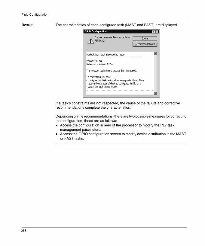
Fipio Configuration
Result The characteristics of each configured task (MAST and FAST) are displayed.
If a task’s constraints are not respected, the cause of the failure and corrective recommendations complete the characteristics.
Depending on the recommendations, there are two possible measures for correcting the configuration, these are as follows:� Access the configuration screen of the processor to modify the PL7 task
management parameters.� Access the FIPIO configuration screen to modify device distribution in the MAST
or FAST tasks.
Close
Recommendation>>
+� ����� �!������� ?
Cannot generate the scan table forFIPIO I/Os
Periodic Mast task in controlled mode
Period: 100 msNetwork cycle time: 177 ms
The network cycle time is greater than the period.
To correct this you can:- configure this task period at a value greater than 177ms- reduce the number of devices configured in this task.- switch this task to free mode
286

Fipio Configuration
Confirmation refused, examples
Introduction The following examples concern the main refusals encountered.
Example 1 The MAST or FAST task has been configured in controlled periodic mode.
The network cycle time is greater than the period.
Close
Recommendation>>
+� ����� �!������� ?
Cannot generate the scan table forFIPIO I/Os
Periodic Mast task in controlled mode
Period: 100 msNetwork cycle time: 177 ms
The network cycle time is greater than the period.
To correct this you can:- configure this task period at a value greater than 177ms- reduce the number of devices configured in this task.- switch this task to free mode
287

Fipio Configuration
Example 2 The MAST task has been configured in cyclic mode.
The network cycle time is greater than the watchdog.
Example 3 The MAST or FAST task has been configured in free periodic mode.
The network cycle time is greater than the watchdog.
Close
Recommendation>>
+� ����� �!������� ?
Cannot generate the scan table forFIPIO I/Os
Cyclic Mast task
Watchdog: 100 msNetwork cycle time: 177 ms
The network cycle time is greater than the watchdog.
To correct this you can:- configure the watchdog of this task period at a value greater than 177ms- reduce the number of devices configured in this task.
Close
Recommendation>>
+� ����� �!������� ?
Cannot generate the scan table forFIPIO I/Os
Periodic Mast task in free mode
Period: 50msWatchdog: 100 msNetwork cycle time: 177 ms
The network cycle time is greater than the watchdog.
To correct this you can:- configure the watchdog of this task period at a value greater than 177ms- reduce the number of devices configured in this task.
288

20
Programming Fipio communicationIntroduction
Subject of this Chapter
This Chapter describes the Programming process during set-up Fipio communication.
What’s in this Chapter?
This chapter contains the following topics:
Topic Page
FIPIO error processing 290
Examples of explicit exchange saturation detection 292
289

Fipio Programming
FIPIO error processing
Introduction FIPIO error processing can be performed with the debugging and diagnostics screens.It can however be useful to perform this processing using a program.
290

Fipio Programming
Algorithm The algorithm shown is an example of a FIPIO bus error detection and management application algorithm
Test bit %S10(general input/output error)
%S10 = 0 ?
Find error on the FIPIO bus via
%S118
Test error on bus X via%S119
%S118 = 0?
Find the word from %SW128 to %SW143, which is different
from FFFF
Find faulty point of connection via
%I\p2c\m.MOD.ERR = 1
Diagnose the connection point using theREAD_STS %CH\p.2.c\0.MOD
function
Find the faultychannel via
%I\p.2.c\m.v.ERR = 1
Diagnose the channel via theREAD_STS %CH\p.2.c\m.v.ERR
function
Find the faulty point of connection using the
%SWi:x word bit which is different from 0
Yes
No input/outputerror
Yes
No
No
There are two differentmethods for finding thefaulty point of connection.The recommended methodis to find it by using systemwords %SW128 to%SW143.
291

Fipio Programming
Examples of explicit exchange saturation detection
Introduction The following examples are given in structured text language, but they can be translated into all the PL7 languages.
They only have to be taken into account if the PL7 application may activate more that 24 explicit functions at the same time and if you want to reiterate a request in the event of explicit exchange saturation.
Management of the READ_STS module
IF (NOT (%MW\0.2.1\0.MOD:x0)) THEN (*no request in progress*)
SET %M0; (*request latch*)(*bit reset to 0 indicating saturation of explicitexchanges*)%SW116:=%SW116 AND 2#1111111111111011;READ_STS %CH\0.2.1\0.MOD;IF (%SW116:x2) THEN
RESET %M0; (*READ_STS retried, saturation hasoccurred*)(*%MW\0.2.1\0.MOD.2:x1 signals a functional error*)
END_IF;END_IF;IF(%M0 AND NOT (%MW\0.2.1\0.MOD:x0)) THEN
(*%MW\0.2.1\0.MOD.2 can be used*)RESET %M0;
END_IF;
292

Fipio Programming
Management of the READ_STS channel
READ_PARAM at connection point 02
IF (NOT (%MW\0.2.1\0.0:x0)) THEN (*no request in progress*)SET %M1; (*request latch from channels 0 to 7*)(*bit reset to 0 indicating saturation of explicitexchanges*)%SW116:=%SW116 AND 2#1111111111111011;READ_STS %CH\0.2.1\0.0;IF (%SW116:x2) THEN
RESET %M1; (*READ_STS retried, saturation hasoccurred*)(*%MW\0.2.1\0.0.2:x6 signals a communication error*)
END_IF;END_IF;IF(%M1 AND NOT (%MW\0.2.1\0.0:x0)) THEN
(*%MW\0.2.1\0.0.2 can be used*)RESET %M1;
END_IF;
IF (NOT (%MW\0.2.2\0.0:x2)) THEN (*no request in progress*)
SET %M2; (*request latch from channels 0 to 7*)
(*bit reset to 0 indicating saturation of explicit
exchanges*)
%SW116:=%SW116 AND 2#1111111111111011;
READ_PARAM %CH\0.2.2\0.0; (*request from the parameters*)
IF ((%MW\0.2.2\0.0.1:x) AND (%SW116:x2)) THEN
(*exchange refused*)
RESET %M2; (*saturation of explicit exchanges*)
END_IF;
END_IF;
IF(%M2 AND NOT (%MW\0.2.2\0.0:x2)) THEN(*reading finished parameters*)
RESET %M2;
END_IF;
293

Fipio Programming
WRITE_PARAM at connection point 02
WRITE_CMD at connection point 02
IF (NOT (%MW\0.2.2\0.0:x2)) THEN (*no request in progress*)
SET %M3; (*request latch from channels 0 to 7*)
(*bit reset to 0 indicating saturation of explicit
exchanges*)
%SW116:=%SW116 AND 2#1111111111111011;
WRITE_PARAM %CH\0.2.2\0.0, (*parameter transmitting*)
IF ((%MW\0.2.2\0.0.1:x2) AND (%SW116:x2)) THEN
(*exchange refused*)
RESET %M3; (*saturation of explicit exchanges*)
END_IF;
END_IF;
IF(%M3 AND NOT (%MW\0.2.2\0.0:x2)) THEN(*end of parameter transmission*)
RESET %M3;
END_IF;
IF (NOT (%MW\0.2.2\0.0:x1)) THEN (*no request in progress*)
SET %M3; (*request latch from channels 0 to 7*)
(*bit reset to 0 indicating saturation of explicit
exchanges*)
%SW116:=%SW116 AND 2#1111111111111011;
WRITE_CMD %CH\0.2.2\0.0; (*command transmitting*)
IF ((%MW\0.2.2\0.0.1:x1) AND (%SW116:x2)) THEN
(*exchange refused*)
RESET %M3; (*saturation of explicit exchanges*)
END_IF;
END_IF;
IF(%M3 AND NOT (%MW\0.2.2\0.0:x1)) THEN(*end of command transmission*)
RESET %M3;
END_IF;
294
21
Debugging a Fipio communicationIntroduction
Subject of this Chapter
This Chapter describes the Debugging process during set-up of Fipio communication.
What’s in this Chapter?
This chapter contains the following topics:
Topic Page
Debugging mode 296
How to access the remote device debugging screens 297
FIPIO bus device debugging screen 298
295

Fipio Debugging
Debugging mode
Introduction Debugging mode can only be accessed in online mode.
This mode: � uses a red square to display when a device is faulty from the FIPIO configuration
screen,� and adjusts and debugs the devices connected to the FIPIO bus from their
application screen.
Inaccessible functions
The following functions can not be accessed from the FIPIO configuration screen in online mode:� adding on a device in online mode,� duplicating or moving a device,� modifying a device,� deleting a device.
A message displayed in the status bar of the PL7 window gives the reason why access is denied.
296

Fipio Debugging
How to access the remote device debugging screens
Introduction This operation describes how to access the debugging screen of a device connected to the FIPIO bus.
Procedure The following table shows the procedure:
Step Action
1 Connect with the manager PLC.
2 Access the hardware configuration screen
3 Double click on the FIPIO connector.
4 Double click on the standard module to debug.
297
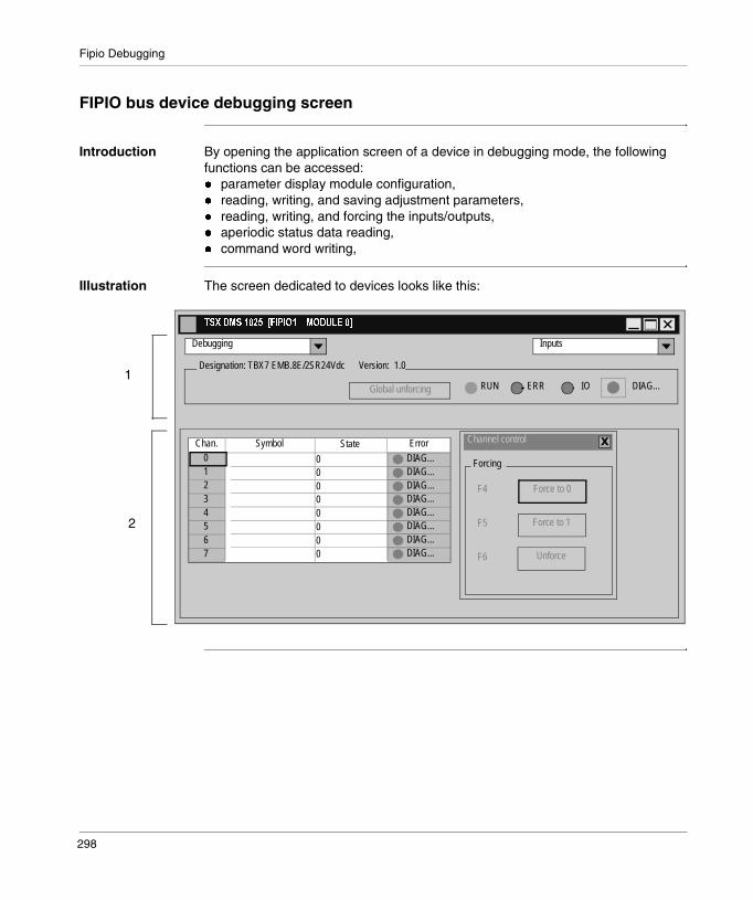
Fipio Debugging
FIPIO bus device debugging screen
Introduction By opening the application screen of a device in debugging mode, the following functions can be accessed:� parameter display module configuration,� reading, writing, and saving adjustment parameters,� reading, writing, and forcing the inputs/outputs,� aperiodic status data reading,� command word writing,
Illustration The screen dedicated to devices looks like this:
����1"���������+� �������"�13%����
Global unforcing
Designation: TBX7 EMB.8E/2SR24Vdc Version: 1.0
Debugging
ERR DIAG...RUN IO
Inputs
Unforce
Force to 1
Force to 0
,Channel control
F4
F5
F6
ForcingDIAG...DIAG...DIAG...DIAG...DIAG...DIAG...DIAG...DIAG...
01234567
Chan. Symbol ErrorState
0000000
0
2
1
298
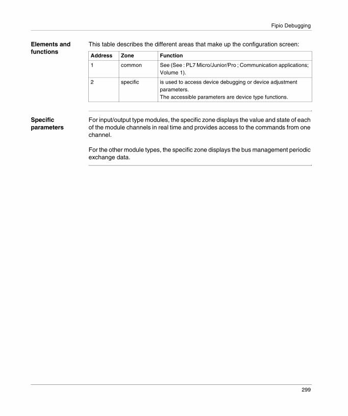
Fipio Debugging
Elements and functions
This table describes the different areas that make up the configuration screen:
Specific parameters
For input/output type modules, the specific zone displays the value and state of each of the module channels in real time and provides access to the commands from one channel.
For the other module types, the specific zone displays the bus management periodic exchange data.
Address Zone Function
1 common See (See : PL7 Micro/Junior/Pro ; Communication applications; Volume 1).
2 specific is used to access device debugging or device adjustment parameters.The accessible parameters are device type functions.
299

Fipio Debugging
300
22
Fipio communication diagnosticsIntroduction
Subject of this Chapter
This Chapter describes the Diagnostics process during set-up of Fipio communication.
What’s in this Chapter?
This chapter contains the following topics:
Topic Page
Diagnostics mode 302
How to access the FIPIO bus monitoring screen 303
Diagnostics screen: FIPIO bus monitoring 304
How to access the device monitoring screen 306
Diagnostics screens: device monitoring 307
How to access the monitoring screen for one device 309
Diagnostics screen: single device monitoring 310
How to access the communication error history screen 312
Diagnostics screen: communication error history 313
301

Fipio Diagnostics
Diagnostics mode
Introduction In online mode it is possible to perform general diagnostics on the bus errors and device faults.
This diagnostic is possible by using screens available in the PL7 or the bits and system words managed by the application software.
Two modes are available: � FIPIO bus monitoring,� device monitoring with or without a fault history.
Communication counters
Every configured connection point (including connection points 0 and 63) has a report variable. This variable contains the communication counter and performance values.
This variable has:� the activity counters numbered from 16#00 to 16#20 and standardized as
WORLDFIP,� the error counters numbered from 16#21 to 16#7F and standardized as
WORLDFIP,� the manufacturer counters numbered 16#80 to 16#FF these counters are not
standardized as WORLDFIP.
The error counters change when there are communication errors on the FIPIO bus.
Diagnostics screens
Four screens display the status of the various counters and thus the communication errors:� The FIPIO bus monitoring screen provides a global view of the FIPIO bus, it
displays the communication errors on the whole bus.� The Device monitoring screen provides a synthesis per connection point; it
features all the connection points and indicates the status of the error counters per connection point.
� The Device monitoring at connection point n screen shows all the counters and their status at a given connection point.
� The Communication fault history screen is a fault history, which dates and retains the fault counter statuses to provide a trace.
Only one screen of each type can be open (one per connection point for the third type). If you try to open a screen which is already open, it will appear instantaneously.
302
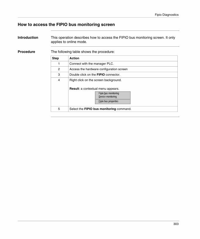
Fipio Diagnostics
How to access the FIPIO bus monitoring screen
Introduction This operation describes how to access the FIPIO bus monitoring screen. It only applies to online mode.
Procedure The following table shows the procedure:
Step Action
1 Connect with the manager PLC.
2 Access the hardware configuration screen
3 Double click on the FIPIO connector.
4 Right click on the screen background.
Result: a contextual menu appears.
5 Select the FIPIO bus monitoring command.
Fipio bus monitoringDevice monitoring
Fipio bus properties
303

Fipio Diagnostics
Diagnostics screen: FIPIO bus monitoring
Introduction This screen gives the user a global view of the bus and indicates the communication faults on the bus.The screen has a list of all the bus communication error counters and indicates their status.
Illustration The screen dedicated to devices looks like this:
Elements and functions
Each line has:� an icon representing the state of the error counter (the reference state being the
state at screen opening):� white for normal state,� red for a faulty counter having changed since the reference state,
� the hexadecimal counter number,� the counter labels (given by the WORLDFIP standard).
Channel 1 No Echo faultChannel 1 Hyper current faultChannel 1 Hypo current faultChannel 1 Cross talk faultFrame fragment faultFCS faultFrame length faultPierced frame faultCoding faultOverrun faultNon identified frame type faultMessage recept queue full faultMessage recept queue full faultIncorrect ADPU length faultReceived APDU type faultElementary cycle time exceedUnderrun fault
+�*���/������������!
212223242B2C2D2E2F3032333435363739
Counter Label
304
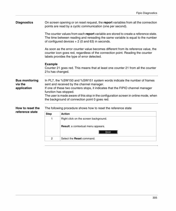
Fipio Diagnostics
Diagnostics On screen opening or on reset request, the report variables from all the connection points are read by a cyclic communication (one per second).
The counter values from each report variable are stored to create a reference state. The time between reading and rereading the same variable is equal to the number of configured devices + 2 (0 and 63) in seconds.
As soon as the error counter value becomes different from its reference value, the counter icon goes red, regardless of the connection point. Reading the counter labels provides the type of error detected.
ExampleCounter 21 goes red. This means that at least one counter 21 from all the counter 21s has changed.
Bus monitoring via the application
In PL7, the %SW150 and %SW151 system words indicate the number of frames sent and received by the channel manager.If one of these two counters stops, it indicates that the FIPIO channel manager function has stopped.The user is made aware of this stop in the configuration screen in online mode, when the background of connection point 0 goes red.
How to reset the reference state
The following procedure shows how to reset the reference state
Step Action
1 Right click on the screen background.
Result: a contextual menu appears.
2 Select the Reset command.
Reset
305

Fipio Diagnostics
How to access the device monitoring screen
Introduction This operation describes how to access the FIPIO bus device monitoring screen. It only applies to online mode.
Procedure The following table shows the procedure:
Step Action
1 Connect with the manager PLC.
2 Access the hardware configuration screen
3 Double click on the FIPIO connector.
4 Right click on the screen background.
Result: a contextual menu appears.
5 Select the Device monitoring command.
Fipio bus monitoringDevice monitoring
Fipio bus properties
306
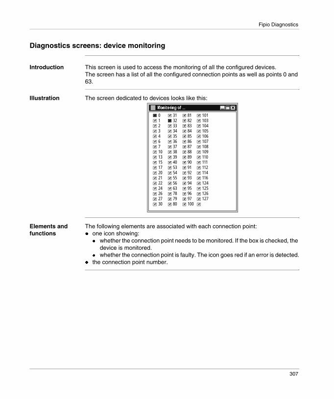
Fipio Diagnostics
Diagnostics screens: device monitoring
Introduction This screen is used to access the monitoring of all the configured devices.The screen has a list of all the configured connection points as well as points 0 and 63.
Illustration The screen dedicated to devices looks like this:
Elements and functions
The following elements are associated with each connection point:� one icon showing:
� whether the connection point needs to be monitored. If the box is checked, the device is monitored.
� whether the connection point is faulty. The icon goes red if an error is detected.� the connection point number.
01234671013151720212224262730
313233343536373839405354555663787980
8182838485868788899091929394959697100
101103104105106107108109110111112114116124125126127
"��������!�� �4
307

Fipio Diagnostics
Diagnostics On screen opening or on reset request, the report variables from all the connection points are read by a cyclic communication (one per second).
The counter values from each report variable are stored to create a reference state. The time between reading and rereading the same variable is equal to the number of configured devices + 2 (0 and 63) in seconds.
A connection point is considered faulty if the value of one of the error counters has changed since the reference state. When the point is faulty, the icon turns red.
Diagnostics are only sent back if there is a communication between the bus manager and the faulty connection point. Errors correspond to the WORLDFIP standard defined error counters.
How to disable device monitoring
The following procedure describes how to disable the device monitoring on the bus.
How to reset the reference state
The following procedure shows how to reset the reference state
Step Action
1 Click on the checkbox belonging to the connection point to be disabled.
Result:The box is no longer checked. In this case this connection’s report variable is no longer read and its reference state is reset.
Step Action
1 Right click on the screen background.
Result: a contextual menu appears.
2 Select the Reset command.
Device monitoringCommunication errors log
Monitoring
Reset
308
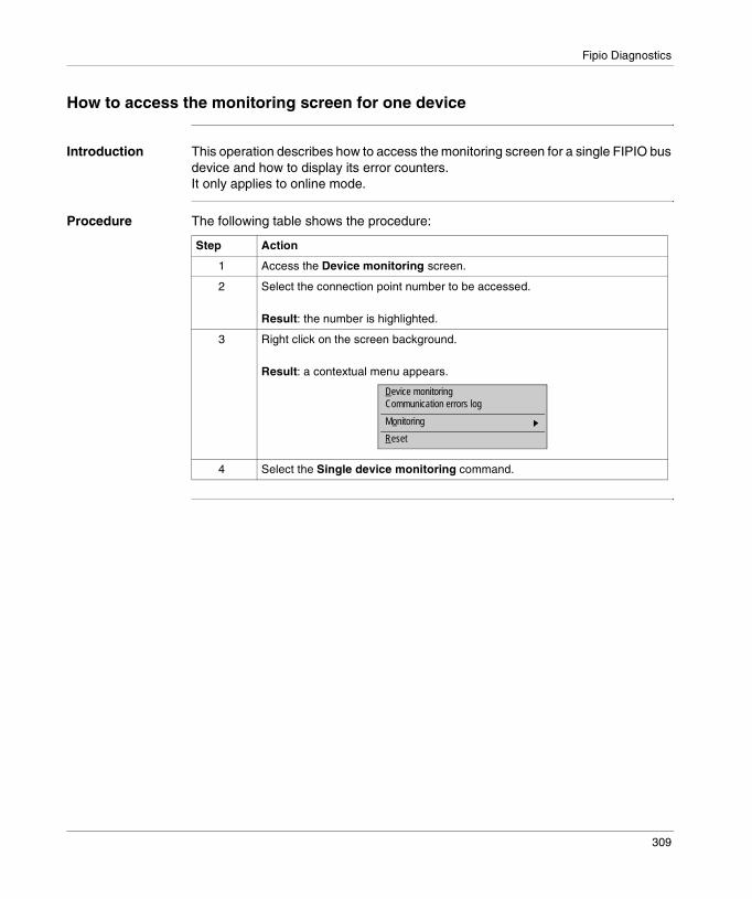
Fipio Diagnostics
How to access the monitoring screen for one device
Introduction This operation describes how to access the monitoring screen for a single FIPIO bus device and how to display its error counters.It only applies to online mode.
Procedure The following table shows the procedure:
Step Action
1 Access the Device monitoring screen.
2 Select the connection point number to be accessed.
Result: the number is highlighted.
3 Right click on the screen background.
Result: a contextual menu appears.
4 Select the Single device monitoring command.
Device monitoringCommunication errors log
Monitoring
Reset
309
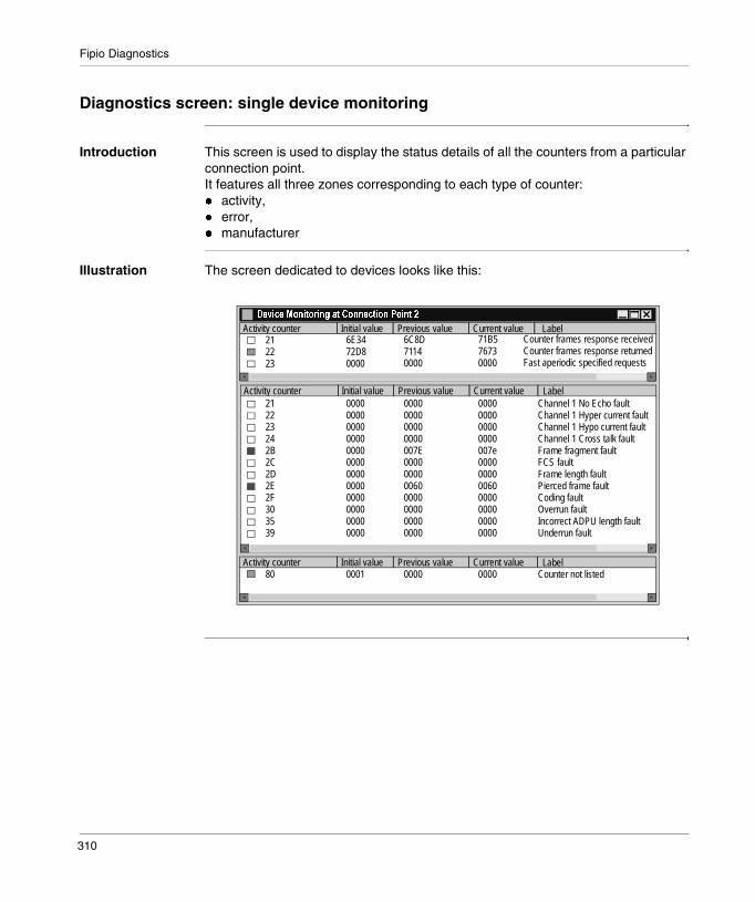
Fipio Diagnostics
Diagnostics screen: single device monitoring
Introduction This screen is used to display the status details of all the counters from a particular connection point. It features all three zones corresponding to each type of counter: � activity,� error,� manufacturer
Illustration The screen dedicated to devices looks like this:
1�.�$��"��������!��������$����� ������
Activity counter LabelInitial value Previous value Current value
Activity counter LabelInitial value Previous value Current value
Activity counter LabelInitial value Previous value Current value
Counter frames response receivedCounter frames response returnedFast aperiodic specified requests
212223242B2C2D2E2F303539
000000000000000000000000000000000000000000000000
0000000000000000007E0000000000600000000000000000
0000000000000000007e0000000000600000000000000000
Channel 1 No Echo faultChannel 1 Hyper current faultChannel 1 Hypo current faultChannel 1 Cross talk faultFrame fragment faultFCS faultFrame length faultPierced frame faultCoding faultOverrun faultIncorrect ADPU length faultUnderrun fault
212223
80
6E3472D80000
6C8D71140000
71B576730000
0001 0000 0000 Counter not listed
310

Fipio Diagnostics
Elements and functions
The following elements are associated with each counter:� one icon indicating the state of the counter since the reference state:
� white: no change,� green: change in the activity or manufacturer counters,� red: change in the error counters (the current value is different from the
reference state).� the hexadecimal counter number,� its hexadecimal reference value,� its hexadecimal value during the last read,� its current hexadecimal value,� its label according to the WORLDFIP standard or the Counter not listed label for
the manufacturer part.
Diagnostics On screen opening or on reset request, the report variables from all the connection points are read by a cyclic communication (one per second).
The counter values from each report variable are stored to create a reference state.
A connection point is considered faulty if the value of one of the error counters has changed since the reference state. When the point is faulty, the icon turns red.
Diagnostics are only sent back if there is a communication between the bus manager and the faulty connection point. Errors correspond to the WORLDFIP standard defined error counters.
How to reset the reference state
The following procedure shows how to reset the reference state
Step Action
1 Right click on the screen background.
Result: a contextual menu appears.
2 Select the Reset command.
Reset
311
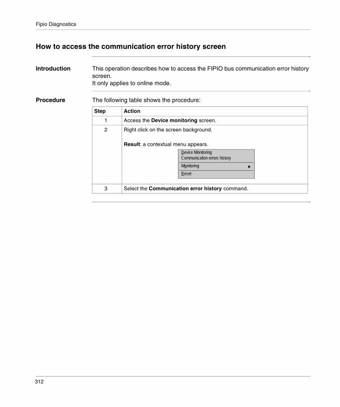
Fipio Diagnostics
How to access the communication error history screen
Introduction This operation describes how to access the FIPIO bus communication error history screen.It only applies to online mode.
Procedure The following table shows the procedure:
Step Action
1 Access the Device monitoring screen.
2 Right click on the screen background.
Result: a contextual menu appears.
3 Select the Communication error history command.
Device MonitoringCommunication errors history
Monitoring
Reset
312

Fipio Diagnostics
Diagnostics screen: communication error history
Introduction This screen has a list of the communication errors from the connection points (plus 0 and 63), which are configured and declared monitored in the Device monitoring screen.
Illustration The screen dedicated to devices looks like this:
Elements and functions
Every time an error counter from a connection point changes, a line is added. It features:� the current date and time of the programming terminal,� the decimal connection point number,� the hexadecimal error counter number,� the hexadecimal counter value,� the counter label according to the WORLDFIP standard.
How to pause/resume the history
This command is used to stop and resume screen updating.
������$�������������&�����-
14/10/1998 14:39:49 2 2B 007E Frame fragment fault14/10/1998 14:39:49 2 2E 0060 Pierced frame fault
Date Time Connection point Counter Value Label
Step Action
1 Right click on the screen background.
Result: a contextual menu appears.
2 Select the Pause history command or Resume history command.
Pause History
Automatic stop of history
Cpy
Reset
Sort
Clear historyReset history
313

Fipio Diagnostics
How to clear history
This command can be accessed if the Pause history function is confirmed. It is used to delete all the lines from the screen.
How to sort the history
This command can be accessed if the Pause history function is confirmed. It is used to sort all the history lines either by date and time or by connection point or counter.
How to copy the history
This command can be accessed if the Pause history function is confirmed. It is used to copy lines selected in text format onto the clipboard.
How to automatically stop the history
When this function is selected, it is used to stop the history when it has reached a maximum number of lines (4000 lines). A message pops up to indicate that this stop has occurred. When the function is not selected and when the maximum number has been reached, new added lines replace the first ones (turning mode).
How to reset the reference state
The following procedure shows how to reset the reference state
Step Action
1 Access the contextual menu.
2 Select the Clear history command
Step Action
1 Access the contextual menu.
2 Select the Sort → by date and time command.
Step Action
1 Access the contextual menu.
2 Select the Sort → by date and time command.
Step Action
1 Access the contextual menu.
2 Select the Automatic history stop command
Result: selecting the command checks the function.
Step Action
1 Access the contextual menu.
2 Select the Reset command.
314
23
Language objects associated with Fipio communicationIntroduction
Subject of this Section
This Chapter introduces language objects associated with Fipio communication.
What’s in this Chapter?
This chapter contains the following topics:
Topic Page
Language objects in implicit exchange 316
Language object for explicit exchange 317
Explicit exchange management and reports 319
315
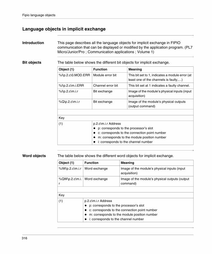
Fipio language objects
Language objects in implicit exchange
Introduction This page describes all the language objects for implicit exchange in FIPIO communication that can be displayed or modified by the application program. (PL7 Micro/Junior/Pro ; Communication applications ; Volume 1)
Bit objects The table below shows the different bit objects for implicit exchange.
Word objects The table below shows the different word objects for implicit exchange.
Object (1) Function Meaning
%I\p.2.c\0.MOD.ERR Module error bit This bit set to 1, indicates a module error (at least one of the channels is faulty,…)
%I\p.2.c\m.i.ERR Channel error bit This bit set at 1 indicates a faulty channel.
%I\p.2.c\m.i.r Bit exchange Image of the module’s physical inputs (input acquisition)
%Q\p.2.c\m.i.r Bit exchange Image of the module’s physical outputs (output command)
Key
(1) p.2.c\m.i.r Address� p: corresponds to the processor’s slot� c: corresponds to the connection point number� m: corresponds to the module position number� i: corresponds to the channel number
Object (1) Function Meaning
%IW\p.2.c\m.i.r Word exchange Image of the module’s physical inputs (input acquisition)
%QW\p.2.c\m.i.r
Word exchange Image of the module’s physical outputs (output command)
Key
(1) p.2.c\m.i.r Address� p: corresponds to the processor’s slot� c: corresponds to the connection point number� m: corresponds to the module position number� i: corresponds to the channel number
316
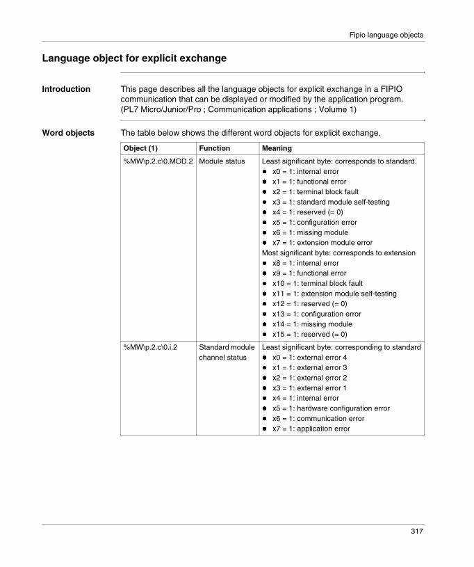
Fipio language objects
Language object for explicit exchange
Introduction This page describes all the language objects for explicit exchange in a FIPIO communication that can be displayed or modified by the application program. (PL7 Micro/Junior/Pro ; Communication applications ; Volume 1)
Word objects The table below shows the different word objects for explicit exchange.
Object (1) Function Meaning
%MW\p.2.c\0.MOD.2 Module status Least significant byte: corresponds to standard.� x0 = 1: internal error� x1 = 1: functional error� x2 = 1: terminal block fault� x3 = 1: standard module self-testing� x4 = 1: reserved (= 0)� x5 = 1: configuration error� x6 = 1: missing module� x7 = 1: extension module errorMost significant byte: corresponds to extension� x8 = 1: internal error� x9 = 1: functional error� x10 = 1: terminal block fault� x11 = 1: extension module self-testing� x12 = 1: reserved (= 0)� x13 = 1: configuration error� x14 = 1: missing module� x15 = 1: reserved (= 0)
%MW\p.2.c\0.i.2 Standard module channel status
Least significant byte: corresponding to standard� x0 = 1: external error 4� x1 = 1: external error 3� x2 = 1: external error 2� x3 = 1: external error 1� x4 = 1: internal error� x5 = 1: hardware configuration error� x6 = 1: communication error� x7 = 1: application error
317

Fipio language objects
Example The example focuses on the channel level diagnostics for a TBX TOR device:
%MW\p.2.c\1.i.2 Extension module channel status
Least significant byte: corresponding to extension� x0 = 1: external error 4� x1 = 1: external error 3� x2 = 1: external error 2� x3 = 1: external error 1� x4 = 1: internal error� x5 = 1: hardware configuration error� x6 = 1: communication error� x7 = 1: application error
Key
(1) p.2.c\m.i.r Address� p: corresponds to the processor’s slot� c: corresponds to the connection point number� m: corresponds to the module position number� i: corresponds to the channel number
������For each connected device, refer to the corresponding documentation for details of task status words.
Object (1) Function Meaning
Object Function Meaning
%MW\p.2.c\0.i.2%MW\p.2.c\1.i.2
Channel status Least significant byte:� x0 = 1: tripped output� x1 = 1: globally tripped� x2 = 1: terminal block fault� x3 = 1: external supply fault� x4 = 1: channel configured but not physically
present� x5 = 1: channel present but different from that
configured� x6 = 1: communication error� x7 = 1: application error
318
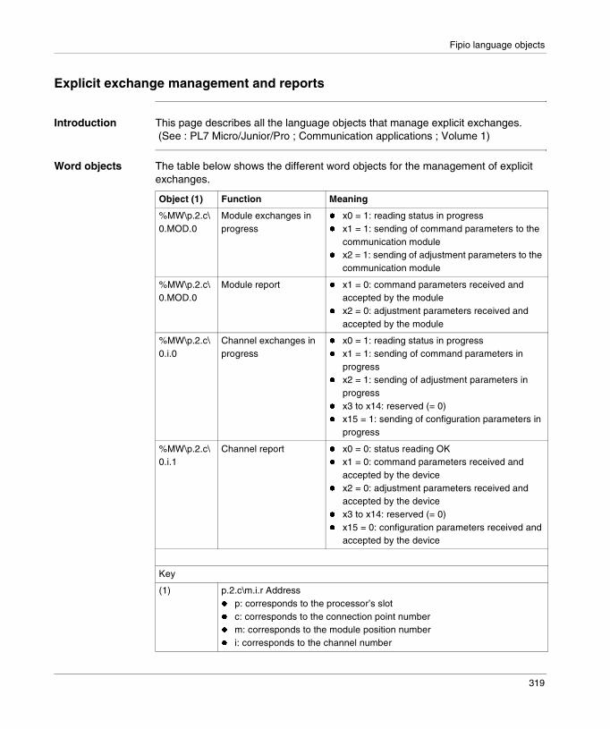
Fipio language objects
Explicit exchange management and reports
Introduction This page describes all the language objects that manage explicit exchanges. (See : PL7 Micro/Junior/Pro ; Communication applications ; Volume 1)
Word objects The table below shows the different word objects for the management of explicit exchanges.
Object (1) Function Meaning
%MW\p.2.c\0.MOD.0
Module exchanges in progress
� x0 = 1: reading status in progress� x1 = 1: sending of command parameters to the
communication module� x2 = 1: sending of adjustment parameters to the
communication module
%MW\p.2.c\0.MOD.0
Module report � x1 = 0: command parameters received and accepted by the module
� x2 = 0: adjustment parameters received and accepted by the module
%MW\p.2.c\0.i.0
Channel exchanges in progress
� x0 = 1: reading status in progress� x1 = 1: sending of command parameters in
progress� x2 = 1: sending of adjustment parameters in
progress� x3 to x14: reserved (= 0)� x15 = 1: sending of configuration parameters in
progress
%MW\p.2.c\0.i.1
Channel report � x0 = 0: status reading OK� x1 = 0: command parameters received and
accepted by the device� x2 = 0: adjustment parameters received and
accepted by the device� x3 to x14: reserved (= 0)� x15 = 0: configuration parameters received and
accepted by the device
Key
(1) p.2.c\m.i.r Address� p: corresponds to the processor’s slot� c: corresponds to the connection point number� m: corresponds to the module position number� i: corresponds to the channel number
319

Fipio language objects
320
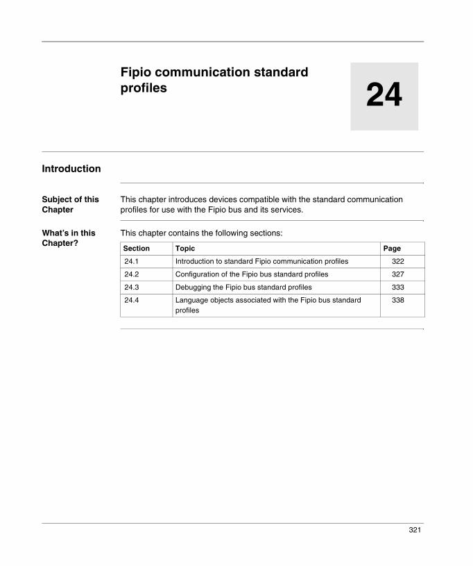
24
Fipio communication standard profilesIntroduction
Subject of this Chapter
This chapter introduces devices compatible with the standard communication profiles for use with the Fipio bus and its services.
What’s in this Chapter?
This chapter contains the following sections:
Section Topic Page
24.1 Introduction to standard Fipio communication profiles 322
24.2 Configuration of the Fipio bus standard profiles 327
24.3 Debugging the Fipio bus standard profiles 333
24.4 Language objects associated with the Fipio bus standard profiles
338
321

Standard profiles
24.1 Introduction to standard Fipio communication profiles
Introduction
Aim of this Section
This Section provides a summary description of the standard profiles of the Fipio bus and its associated services.
What’s in this Section?
This section contains the following topics:
Topic Page
Standard profiles: general 323
Designation of a standard profile 324
List of the standard profiles proposed in catalog by PL7 325
322
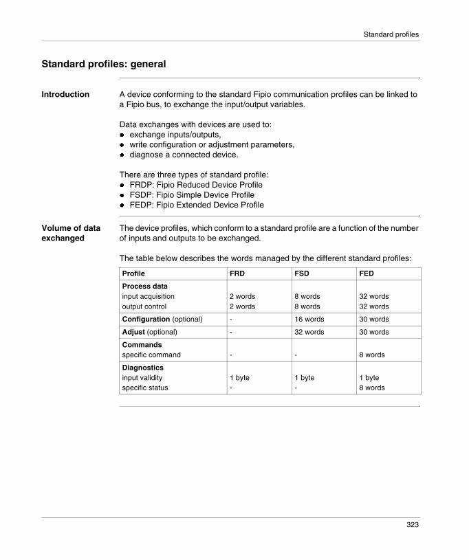
Standard profiles
Standard profiles: general
Introduction A device conforming to the standard Fipio communication profiles can be linked to a Fipio bus, to exchange the input/output variables.
Data exchanges with devices are used to: � exchange inputs/outputs,� write configuration or adjustment parameters,� diagnose a connected device.
There are three types of standard profile:� FRDP: Fipio Reduced Device Profile� FSDP: Fipio Simple Device Profile� FEDP: Fipio Extended Device Profile
Volume of data exchanged
The device profiles, which conform to a standard profile are a function of the number of inputs and outputs to be exchanged.
The table below describes the words managed by the different standard profiles:
Profile FRD FSD FED
Process datainput acquisitionoutput control
2 words2 words
8 words8 words
32 words32 words
Configuration (optional) - 16 words 30 words
Adjust (optional) - 32 words 30 words
Commandsspecific command - - 8 words
Diagnosticsinput validityspecific status
1 byte-
1 byte-
1 byte8 words
323

Standard profiles
Designation of a standard profile
Introduction A device conforming to the standard Fipio communication profiles is defined by assigning one of the STD_P family standard profiles to it at the Fipio connection point.
The family consists of a standard profile reference list.
How the reference is made up
Each reference is made up of several significant codes:� the standard profile used:
� FRD� FSD� FED
� the connected device structure:� C: Compact� M: Modular
� the number and type of objects exchanged with the manager: corresponds to the input/output exchange volume in 16 bit words� 2 words� 8 words� 32 words
� P: corresponds to the presence of configuration or adjustment parameters (chosen).
FRD profile the reference is made up of the following:
FSD profile the reference is made up of the following:
FED profile the reference is made up of the following:
Profile Structure Number of objects Parameter
FRD C 2 -
P
Profile Structure Number of objects Parameter
FSD C 8 -
M P
Profile Structure Number of objects Parameter
FED C 32 -
M P
324
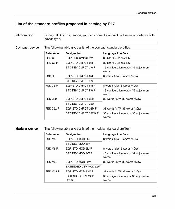
Standard profiles
List of the standard profiles proposed in catalog by PL7
Introduction During FIPIO configuration, you can connect standard profiles in accordance with device type.
Compact device The following table gives a list of the compact standard profiles:
Modular device The following table gives a list of the modular standard profiles:
Reference Designation Language interface
FRD C2 EQP RED CMPCT 2M 32 bits %I, 32 bits %Q
FRD C2 P EQP STD CMPCT 2M P 32 bits %I, 32 bits %Q
STD DEV CMPCT 2W P 16 configuration words, 32 adjustment words
FSD C8 EQP STD CMPCT 8M 8 words %IW, 8 words %QW
STD DEV CMPCT 8W
FSD C8 P EQP STD CMPCT 8M P 8 words %IW, 8 words %QW
STD DEV CMPCT 8W P 16 configuration words, 32 adjustment words
FED C32 EQP STD CMPCT 32M 32 words %IW, 32 words %QW
STD DEV CMPCT 32W
FED C32 P EQP STD CMPCT 32M P 32 words %IW, 32 words %QW
STD DEV CMPCT 328W P 30 configuration words, 30 adjustment words
Reference Designation Language interface
FSD M8 EQP STD MOD 8M 8 words %IW, 8 words %QW
STD DEV MOD 8W
FSD M8 P EQP STD MOD 8M P 8 words %IW, 8 words %QW
STD DEV MOD 8W P 16 configuration words, 32 adjustment words
FED M32 EQP STD MOD 32M 32 words %IW, 32 words %QW
EXTENDED DEV MOD 32W
FED M32 P EQP STD MOD 32M P 32 words %IW, 32 words %QW
EXTENDED DEV MOD 328W P
30 configuration words, 30 adjustment words
325
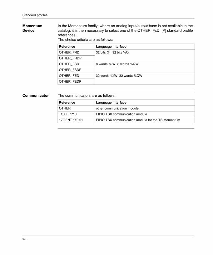
Standard profiles
Momentum Device
In the Momentum family, where an analog input/output base is not available in the catalog, it is then necessary to select one of the OTHER_FxD_[P] standard profile references.The choice criteria are as follows:
Communicator The communicators are as follows:
Reference Language interface
OTHER_FRD 32 bits %I, 32 bits %Q
OTHER_FRDP
OTHER_FSD 8 words %IW, 8 words %QW
OTHER_FSDP
OTHER_FED 32 words %IW, 32 words %QW
OTHER_FEDP
Reference Language interface
OTHER other communication module
TSX FPP10 FIPIO TSX communication module
170 FNT 110 01 FIPIO TSX communication module for the TS Momentum
326
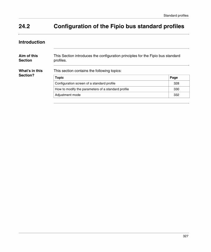
Standard profiles
24.2 Configuration of the Fipio bus standard profiles
Introduction
Aim of this Section
This Section introduces the configuration principles for the Fipio bus standard profiles.
What’s in this Section?
This section contains the following topics:
Topic Page
Configuration screen of a standard profile 328
How to modify the parameters of a standard profile 330
Adjustment mode 332
327

Standard profiles
Configuration screen of a standard profile
Introduction The configuration screen of a standard profile reuses the parameters of all other devices configured on the FIPIO bus (see Configuration screen of an FIPIO device).
However, some parameters are exclusive to it. In the rest of this document, only the part specific to the standard profiles is explained.
Illustration The screen dedicated to the device looks like this:
+�1�"2� ���+� ���2�����"�13%����
Local configurationMAST
Configuration Designation: EQP STD MOD 8MP
Default configuration Base
Channel 0
Decimal
Parameter Symbol Value%KW\0.2.18\0.0.0 16#8040%KW\0.2.18\0.0.1 16#0%KW\0.2.18\0.0.2 0%KW\0.2.18\0.0.3 0%KW\0.2.18\0.0.4 0%KW\0.2.18\0.0.5 16#4%KW\0.2.18\0.0.6 0%KW\0.2.18\0.0.7 0
Task:1
23
4
328
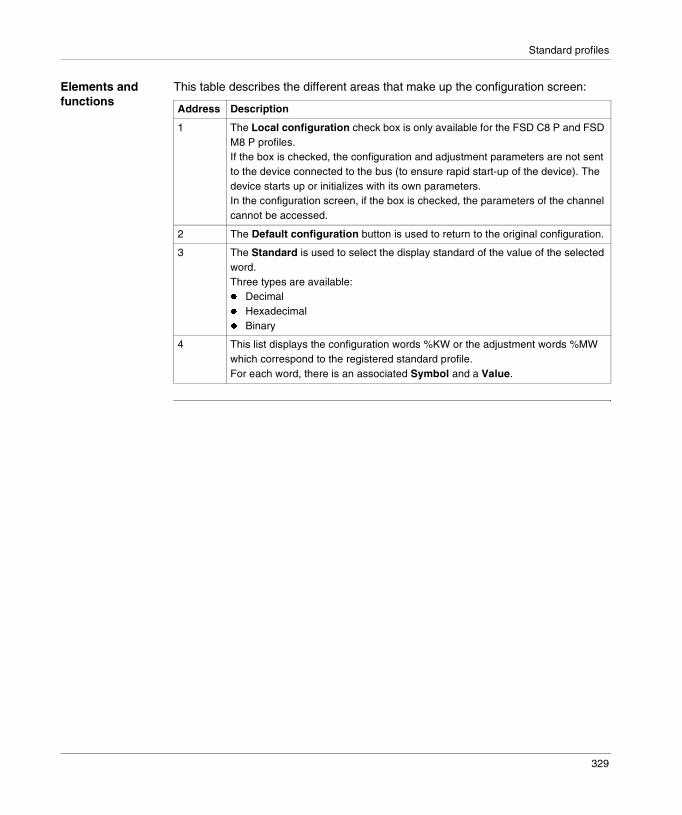
Standard profiles
Elements and functions
This table describes the different areas that make up the configuration screen:
Address Description
1 The Local configuration check box is only available for the FSD C8 P and FSD M8 P profiles.If the box is checked, the configuration and adjustment parameters are not sent to the device connected to the bus (to ensure rapid start-up of the device). The device starts up or initializes with its own parameters.In the configuration screen, if the box is checked, the parameters of the channel cannot be accessed.
2 The Default configuration button is used to return to the original configuration.
3 The Standard is used to select the display standard of the value of the selected word.Three types are available:� Decimal� Hexadecimal� Binary
4 This list displays the configuration words %KW or the adjustment words %MW which correspond to the registered standard profile.For each word, there is an associated Symbol and a Value.
329
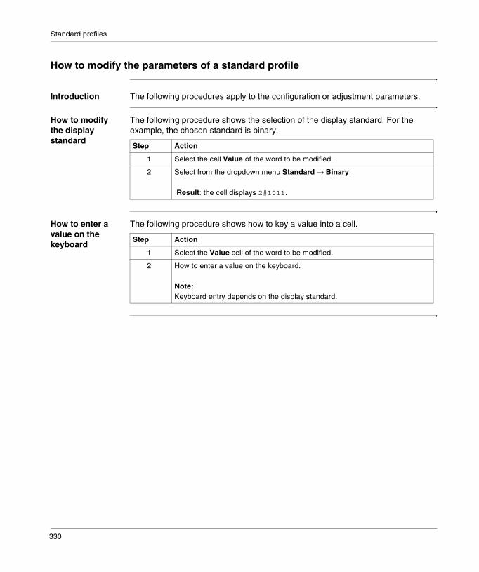
Standard profiles
How to modify the parameters of a standard profile
Introduction The following procedures apply to the configuration or adjustment parameters.
How to modify the display standard
The following procedure shows the selection of the display standard. For the example, the chosen standard is binary.
How to enter a value on the keyboard
The following procedure shows how to key a value into a cell.
Step Action
1 Select the cell Value of the word to be modified.
2 Select from the dropdown menu Standard → Binary.
Result: the cell displays 2#1011.
Step Action
1 Select the Value cell of the word to be modified.
2 How to enter a value on the keyboard.
Note:Keyboard entry depends on the display standard.
330
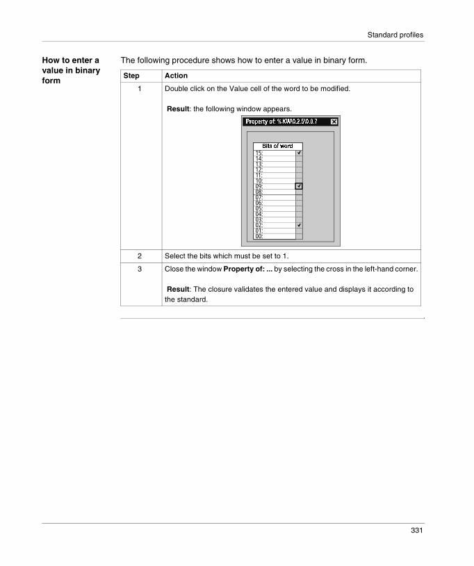
Standard profiles
How to enter a value in binary form
The following procedure shows how to enter a value in binary form.
Step Action
1 Double click on the Value cell of the word to be modified.
Result: the following window appears.
2 Select the bits which must be set to 1.
3 Close the window Property of: ... by selecting the cross in the left-hand corner.
Result: The closure validates the entered value and displays it according to the standard.
��*���-�� 5�6�78�(�(�8�(�(�
15:14:13:12:11:10:09:08:07:06:05:04:03:02:01:00:
0����� �9��#
331

Standard profiles
Adjustment mode
Introduction Adjustment mode is accessed from the hardware configuration menu of the application browser. The principal is the same as for configuration mode, and the adjustment words are %MW.There are 32 possible words for the FSD and FRD profiles and 30 words for the FED profiles.
Illustration The adjustment screen dedicated to the device looks like this:
+�1�2� ���+� ��������"�13%����
Local configurationMAST
Configuration Designation: EQP STD CMPCT 8MP
Default configuration Base
Channel 0
Decimal
�������� �-�/�: ;�:��%KW\0.2.5\0.0.0 0%KW\0.2.5\0.0.1 0%KW\0.2.5\0.0.2 0%KW\0.2.5\0.0.3 0%KW\0.2.5\0.0.4 0%KW\0.2.5\0.0.5 0%KW\0.2.5\0.0.6 0%KW\0.2.5\0.0.7 0
Task:
332
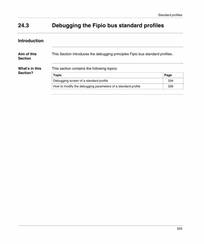
Standard profiles
24.3 Debugging the Fipio bus standard profiles
Introduction
Aim of this Section
This Section introduces the debugging principles Fipio bus standard profiles.
What’s in this Section?
This section contains the following topics:
Topic Page
Debugging screen of a standard profile 334
How to modify the debugging parameters of a standard profile 336
333
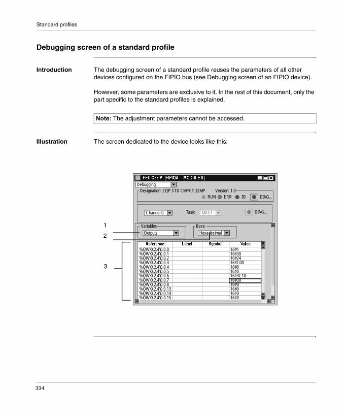
Standard profiles
Debugging screen of a standard profile
Introduction The debugging screen of a standard profile reuses the parameters of all other devices configured on the FIPIO bus (see Debugging screen of an FIPIO device).
However, some parameters are exclusive to it. In the rest of this document, only the part specific to the standard profiles is explained.
Illustration The screen dedicated to the device looks like this:
������The adjustment parameters cannot be accessed.
+�1���� ���+� ��<�����"�13%����
MAST
Debugging Designation: EQP STD CMPCT 32MP Version: 1.0
Base
Channel 0
%�/�: �-�/�: ;�:��%QW\0.2.4\0.0.0 16#1%QW\0.2.4\0.0.1 16#30%QW\0.2.4\0.0.2 16#24%QW\0.2.4\0.0.3 16#C00%QW\0.2.4\0.0.4 16#0%QW\0.2.4\0.0.5 16#0%QW\0.2.4\0.0.6 16#3C10%QW\0.2.4\0.0.7 16#30%QW\0.2.4\0.0.8 16#0%QW\0.2.4\0.0.13 16#0%QW\0.2.4\0.0.14 16#0%QW\0.2.4\0.0.15 16#0
Task:
�� ����$�
ERR DIAG...RUN IO
Variables
Outputs
DIAG...
Hexadecimal
1
2
3
334
Standard profiles
Elements and functions
This table describes the different areas that make up the configuration screen:
Address Description
1 This dropdown list allows the choice of periodic exchange:� of the input parts,� of the output parts.
2 The Standard window is used to select the display standard of the value of the selected word.Three types are available:� Decimal� Hexadecimal� Binary
3 This list displays the input words %IW or the output words %QW which correspond to the registered standard profile.For each word there is an associated Wording, a Symbol and a Value.
335
Standard profiles
How to modify the debugging parameters of a standard profile
Introduction The following procedures apply to the debugging parameters.
How to modify the display standard
The following procedure shows the selection of the display standard. For the example, the chosen standard is binary.
How to enter a value on the keyboard
The following procedure shows how to key a value into a cell.
Step Action
1 Select the Value cell of the word to be modified.
2 Select from the dropdown menu Standard → Binary.
Result: the cell displays 2#1011.
Step Action
1 Select the Value cell of the word to be modified.
2 How to enter a value on the keyboard.
Note:Keyboard entry depends on the display standard.
336

Standard profiles
How to enter a value in binary form
The following procedure shows how to enter a value in binary form. It is only valid for the output parts.
Step Action
1 Double click on the Value cell of the word to be modified.
Result: the following window appears.
2 Select the bits which must be set to 1.
3 Close the window Property of: ... by selecting the cross in the left-hand corner.
Result: The closure validates the entered value and displays it according to the standard.
��*���-�� 5�6�78�(�(�8�(�(�
15:14:13:12:11:10:09:08:07:06:05:04:03:02:01:00:
0����� �9��#
337
Standard profiles
24.4 Language objects associated with the Fipio bus standard profiles
Introduction
Aim of this Section
This section introduces the language objects associated with the Fipio bus standard profiles.
What’s in this Section?
This section contains the following topics:
Topic Page
Summary of the objects which can be accessed via the standard profiles 339
Language objects in implicit exchange 341
Language object for explicit exchange 343
Language objects associated with configuration 346
338
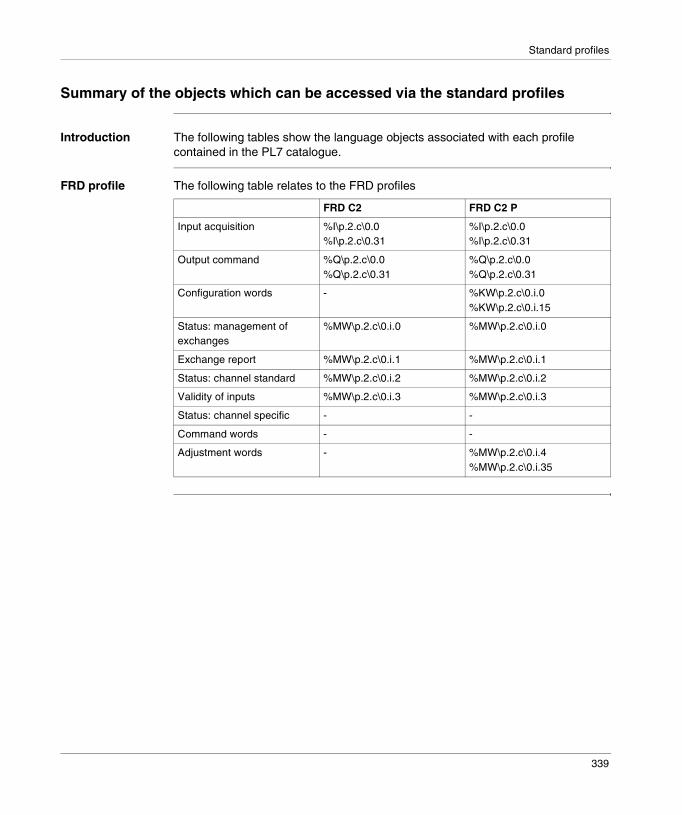
Standard profiles
Summary of the objects which can be accessed via the standard profiles
Introduction The following tables show the language objects associated with each profile contained in the PL7 catalogue.
FRD profile The following table relates to the FRD profiles
FRD C2 FRD C2 P
Input acquisition %I\p.2.c\0.0%I\p.2.c\0.31
%I\p.2.c\0.0%I\p.2.c\0.31
Output command %Q\p.2.c\0.0%Q\p.2.c\0.31
%Q\p.2.c\0.0%Q\p.2.c\0.31
Configuration words - %KW\p.2.c\0.i.0%KW\p.2.c\0.i.15
Status: management of exchanges
%MW\p.2.c\0.i.0 %MW\p.2.c\0.i.0
Exchange report %MW\p.2.c\0.i.1 %MW\p.2.c\0.i.1
Status: channel standard %MW\p.2.c\0.i.2 %MW\p.2.c\0.i.2
Validity of inputs %MW\p.2.c\0.i.3 %MW\p.2.c\0.i.3
Status: channel specific - -
Command words - -
Adjustment words - %MW\p.2.c\0.i.4%MW\p.2.c\0.i.35
339

Standard profiles
FSD profile The following table relates to the FSD profiles
FED profile The following table relates to the FED profiles
FSD C/M8 FSD C/M8 P
Input acquisition %IW\p.2.c\0.0%IW\p.2.c\0.7
%IW\p.2.c\0.0%IW\p.2.c\0.7
Output command %QW\p.2.c\0.0%QW\p.2.c\0.7
%QW\p.2.c\0.0%QW\p.2.c\0.7
Configuration words - %KW\p.2.c\0.i.0%KW\p.2.c\0.i.15
Status: management of exchanges
%MW\p.2.c\0.i.0 %MW\p.2.c\0.i.0
Exchange report %MW\p.2.c\0.i.1 %MW\p.2.c\0.i.1
Status: channel standard %MW\p.2.c\0.i.2 %MW\p.2.c\0.i.2
Validity of inputs %MW\p.2.c\0.i.3 %MW\p.2.c\0.i.3
Status: channel specific - -
Command words - -
Adjustment words - %MW\p.2.c\0.i.4%MW\p.2.c\0.i.35
FED C/M32 FED C/M32 P
Input acquisition %IW\p.2.c\0.0%IW\p.2.c\0.31
%IW\p.2.c\0.0%IW\p.2.c\0.31
Output command %QW\p.2.c\0.0%QW\p.2.c\0.31
%QW\p.2.c\0.0%QW\p.2.c\0.31
Configuration words - %KW\p.2.c\0.i.0%KW\p.2.c\0.i.29
Status: management of exchanges
%MW\p.2.c\0.i.0 %MW\p.2.c\0.i.0
Exchange report %MW\p.2.c\0.i.1 %MW\p.2.c\0.i.1
Status: channel standard %MW\p.2.c\0.i.2 %MW\p.2.c\0.i.2
Validity of inputs %MW\p.2.c\0.i.3 %MW\p.2.c\0.i.3
Status: channel specific %MW\p.2.c\0.i.4%MW\p.2.c\0.i.11
%MW\p.2.c\0.i.4%MW\p.2.c\0.i.11
Command words %MW\p.2.c\0.i.12%MW\p.2.c\0.i.19
%MW\p.2.c\0.i.12%MW\p.2.c\0.i.19
Adjustment words - %MW\p.2.c\0.i.20%MW\p.2.c\0.i.49
340

Standard profiles
Language objects in implicit exchange
Introduction This page describes all the language objects for implicit exchange associated with the standard profiles for FIPIO communication that can be displayed or modified by the application program. (PL7 Micro/Junior/Pro ; Communication applications ; Volume 1)
Bit objects The table below shows the different bit objects for implicit exchange.
Object (1) Function Meaning
%I\p.2.c\0.MOD.ERR
Module error bit This bit set to 1, indicates a module error (at least one of the channels is faulty,…)
%I\p.2.c\m.i.ERR
Channel error bit This bit set at 1 indicates a faulty channel.
%I\p.2.c\0.0 to %I\p.2.c\0.31
Bit exchange Acquiring input bits for FRD profiles
%Q\p.2.c\0.0 to%Q\p.2.c\0.31
Bit exchange Acquiring output bits for FRD profiles
Key
(1) p.2.c Address� p: corresponds to the processor’s slot� c: corresponds to the connection point number
341
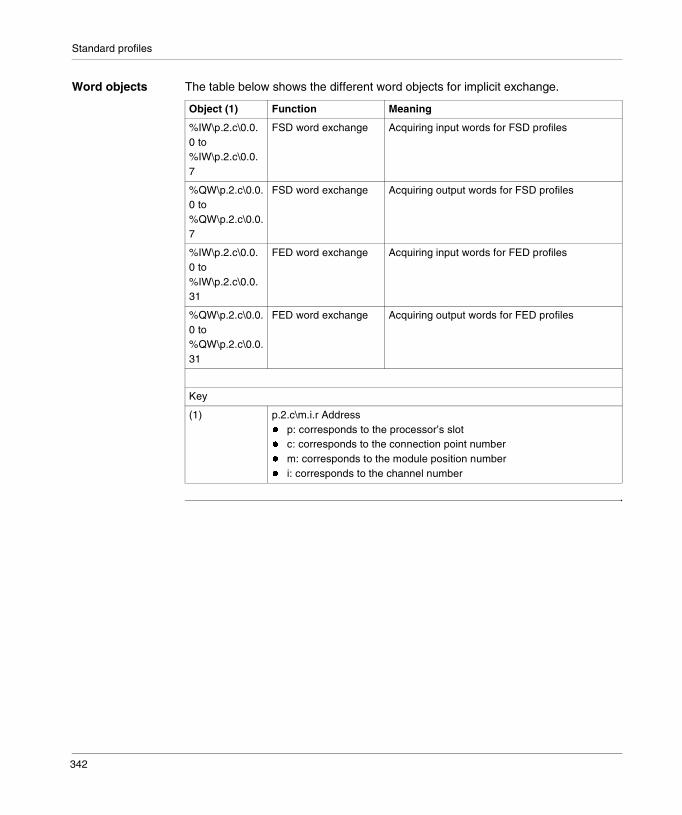
Standard profiles
Word objects The table below shows the different word objects for implicit exchange.
Object (1) Function Meaning
%IW\p.2.c\0.0.0 to%IW\p.2.c\0.0.7
FSD word exchange Acquiring input words for FSD profiles
%QW\p.2.c\0.0.0 to%QW\p.2.c\0.0.7
FSD word exchange Acquiring output words for FSD profiles
%IW\p.2.c\0.0.0 to%IW\p.2.c\0.0.31
FED word exchange Acquiring input words for FED profiles
%QW\p.2.c\0.0.0 to%QW\p.2.c\0.0.31
FED word exchange Acquiring output words for FED profiles
Key
(1) p.2.c\m.i.r Address� p: corresponds to the processor’s slot� c: corresponds to the connection point number� m: corresponds to the module position number� i: corresponds to the channel number
342

Standard profiles
Language object for explicit exchange
Introduction This page describes all the language objects for explicit exchange associated with the standard profiles for FIPIO communication that can be displayed or modified by the application program. (PL7 Micro/Junior/Pro ; Communication applications ; Volume 1)
Word objects common to all the profiles
The table below shows the different word objects for explicit exchange.
Object (1) Function Meaning
%MW\p.2.c\0.MOD.2
Module status Least significant byte: corresponds to standard.� x0 = 1: internal error� x1 = 1: functional error� x2 = 1: terminal block fault� x3 = 1: standard module self-testing� x4 = 1: reserved (= 0)� x5 = 1: configuration error� x6 = 1: missing module� x7 = 1: extension module errorMost significant byte: corresponds to extension� x8 = 1: internal error� x9 = 1: functional error� x10 = 1: terminal block fault� x11 = 1: extension module self-testing� x12 = 1: reserved (= 0)� x13 = 1: configuration error� x14 = 1: missing module� x15 = 1: reserved (= 0)
%MW\p.2.c\0.i.2 Standard module channel status
Least significant byte: corresponding to standard� x0 = 1: external error 4� x1 = 1: external error 3� x2 = 1: external error 2� x3 = 1: external error 1� x4 = 1: internal error� x5 = 1: hardware configuration error� x6 = 1: communication error� x7 = 1: application error
%MW\p.2.c\0.i.3 Validity of inputs For FRD, FSD and FED profiles the least significant byte is specific to the connected device. Refer to the documentation for the device.
Key
343

Standard profiles
Internal words for FRD and FSD profiles
The following table shows the internal words specific to FRD and FSD profiles:
Internal words for the FED profiles
The following table shows the internal words specific to the FED profiles:
(1) p.2.c\m.i.r Address� p: corresponds to the processor’s slot� c: corresponds to the connection point number� m: corresponds to the module position number� i: corresponds to the channel number
������For each connected device, refer to the corresponding documentation for details of task status words.
Object (1) Function Meaning
Object Function Meaning
%MW\p.2.c\0.i.4to%MW\p.2.c\0.i.35
Adjustment parameters
32 specific adjustment words.Parameters which can be accessed in read and write format via the WRITE_PARAM, READ_PARAM, SAVE_PARAM and RESTORE_PARAM functions.
Key
(1) p.2.c\m.i.r Address� p: corresponds to the processor’s slot� c: corresponds to the connection point number� m: corresponds to the module position number� i: corresponds to the channel number
Object Function Meaning
%MW\p.2.c\0.i.4to%MW\p.2.c\0.i.11
Specific status 8 specific status words.Parameters which can be accessed in read format via the READ_STATUS function.
%MW\p.2.c\0.i.12to%MW\p.2.c\0.i.19
Specific channel level command
8 specific command words.Parameters which can be accessed in write format by the WRITE_CMD function.
%MW\p.2.c\0.i.20to%MW\p.2.c\0.i.49
Adjustment parameters
32 specific adjustment words.Parameters which can be accessed in read and write format via the WRITE_PARAM, READ_PARAM, SAVE_PARAM and RESTORE_PARAM functions.
Key
344

Standard profiles
(1) p.2.c\m.i.r Address� p: corresponds to the processor’s slot� c: corresponds to the connection point number� m: corresponds to the module position number� i: corresponds to the channel number
Object Function Meaning
345

Standard profiles
Language objects associated with configuration
Introduction This page describes all the configuration language objects associated with the FIPIO communication agents that can be displayed by the agent application program.
Internal constants
The following table describes the internal constants:
Object Function Meaning
%KW\p.2.c\0.0.0 to %KW\p.2.c\0.15
Configuration words at channel level
They contain channel parameters set via the configuration editor for FRD and FSD profiles.
%KW\p.2.c\0.0.0 to %KW\p.2.c\0.29
Configuration words at channel level
They contain channel parameters set via the configuration editor for FED profiles.
346

25
Fipio AgentIntroduction
Subject of this Chapter
This Chapter introduces the Agent devices on the Fipio bus and its services.
What’s in this Chapter?
This chapter contains the following sections:
Section Topic Page
25.1 Introduction to Fipio Agents 348
25.2 Configuration of Fipio Agents 355
25.3 Debugging Fipio Agents 358
25.4 Language objects associated with the Fipio Agents 359
347

Fipio Agent
25.1 Introduction to Fipio Agents
Introduction
Aim of this Section
This section provides a summary description of the agents on the Fipio bus and their associated services.
What’s in this Section?
This section contains the following topics:
Topic Page
FIPIO Agent: General 349
Periodic data exchange 350
Special cases 351
Communication from an FIPIO Agent 353
348
Fipio Agent
FIPIO Agent: General
Introduction The Micro or Premium PLCs, equipped with the PCMCIA TSX FPP 10 card on their built-in communication channel, are agents on the FIPIO bus.
The FIPIO function agent is used to perform two types of data exchange: � periodic exchanges of information with the manager (shared variables type),� aperiodic exchanges of messages with the manager, from CCX 17 devices or
with other agents.
������This function is available with the TSX FPP 10 card, minimum version V1.8.
349

Fipio Agent
Periodic data exchange
Introduction Each FIPIO Agent PLC uses 64 consecutive %MW words to exchange the periodic data. � The 32 first words are reserved for transmitting the information to the manager.� The 32 remaining words are reserved for receiving the information.
Viewing the exchanges
The following chart illustrates the exchanges between an FIPIO Agent and a Premium manager.
������The status %MW words and the command %MW are not significant.
%IW\0.2.1\0.0.0
%IW\0.2.1\0.0.15
%IW\0.2.1\0.0.16
%IW\0.2.1\0.0.31
%QW\0.2.1\0.0.0
%QW\0.2.1\0.0.15
%QW\0.2.1\0.0.16
%QW\0.2.1\0.0.31
%IW\0.2.4\0.0.0
%IW\0.2.4\0.0.15
%IW\0.2.4\0.0.16
%IW\0.2.4\0.0.31
%QW\0.2.4\0.0.0
%QW\0.2.4\0.0.15
%QW\0.2.4\0.0.16
%QW\0.2.4\0.0.31
%MW...+32
%MW...+63
%MW...
%MW...+31
%MW...+32
%MW...+63
%MW...
%MW...+31
TSX 57 FIPIO bus manager
TSX 57 Agent
TSX 37 Agent
1
2
3
4
Language view of the manager Language view of the agent
350

Fipio Agent
Special cases
Introduction A Premium PLC which is registered as an FIPIO Agent can communicate with aTSX 47-107 or APRIL 5000 manager.
For these uses, an FIPIO Agent is registered on the bus by registering a standard profile to the connection point.
The registered standard profile is as follows:� Device family: STD_P� Standard: FED M32� Communicator: TSX FPP 10
351

Fipio Agent
Exchanges with a TSX 47-107
The following chart illustrates the exchanges between an FIPIO Agent and a TSX 47-107 manager.
RIWA1,0,0
RIWA1,0,15
RIWB1,0,16
RIWB1,0,31
%MW...+32
%MW...+63
%MW...
%MW...+31
%MW...+32
%MW...+63
%MW...
%MW...+31
TSX 47-107 FIPIO bus manager
TSX 57 Agent
TSX 37 Agent
1
2
3
4
ROWA1,0,0
ROWA1,0,15
ROWB1,0,16
ROWB1,0,31
RIWA4,0,0
RIWA4,0,15
RIWB4,0,16
RIWB4,0,31
ROWA4,0,0
ROWA4,0,15
ROWB4,0,16
ROWB4,0,31
Language view of the manager Language view of the agent
352
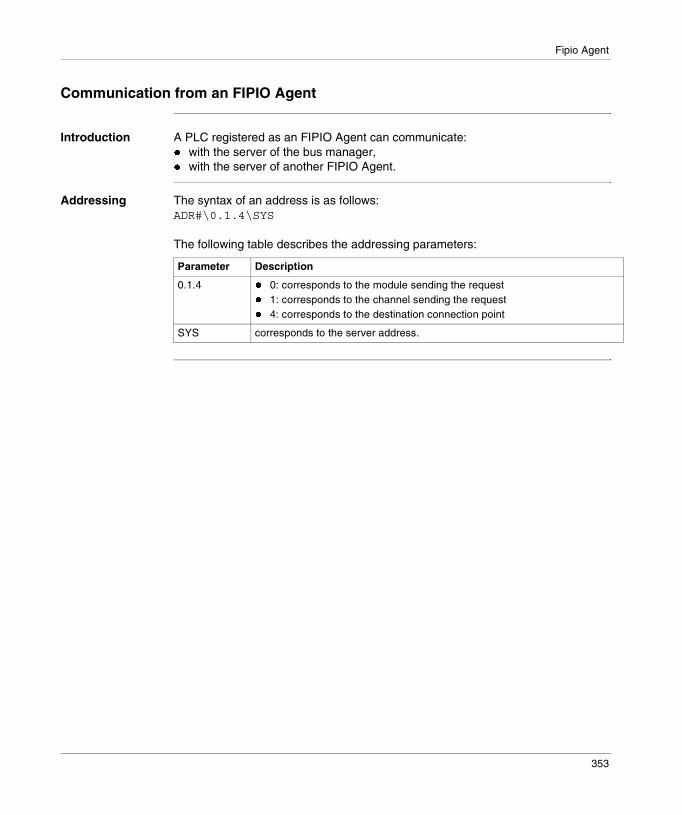
Fipio Agent
Communication from an FIPIO Agent
Introduction A PLC registered as an FIPIO Agent can communicate:� with the server of the bus manager,� with the server of another FIPIO Agent.
Addressing The syntax of an address is as follows:ADR#\0.1.4\SYS
The following table describes the addressing parameters:
Parameter Description
0.1.4 � 0: corresponds to the module sending the request� 1: corresponds to the channel sending the request� 4: corresponds to the destination connection point
SYS corresponds to the server address.
353

Fipio Agent
Example Example of access the system of the different PLCs
The FIPIO Agent PLC at address 1 reads 10 words in the FIPIO Agent PLC at address 4.READ_VAR(ADR#\0.1.4\SYS, ‘%MW’, 0, 10, %MW10:10, %MW100:4)
Manager
1
0
4
63
ADR#\1.1.0\SYSAccessing the manager server
ADR#\0.1.4\SYSAccessing theFIPIO Agent 4server
ADR#\0.1.1\SYSAccessing theFIPIO Agent 1server
ADR#\0.1.4\SYSAccessing theFIPIO Agent 4server
354
Fipio Agent
25.2 Configuration of Fipio Agents
Introduction
Aim of this Section
This Section introduces the configuration principles for Fipio Agents.
What’s in this Section?
This section contains the following topics:
Topic Page
How to access the FIPIO Agent parameters via PCMCIA cards 356
FIPIO Agent configuration screen 357
355

Fipio Agent
How to access the FIPIO Agent parameters via PCMCIA cards
Introduction The creation of an application setting up FIPIO Agents requires the configuration of the communication channel of the PLC registered as an FIPIO Agent.
This operation describes how to access the configuration parameters of the FIPIO Agent link via the PCMCIA TSX FPP card for Micro/Premium PLCs.
How to access the link
The following table shows the procedure for accessing the FIPIO link:
Step Action
1 Access the communication channel configuration screen.
2 From the dropdown menu, select the communication channel CHANNEL 1Example
3 Select one of the following PCMCIA cards from the dropdown menu:� TSX FPP 10 PCMCIA CARD FIPIOExample
CHANNEL 1 CHANNEL 1
(No PCMCIA submodule)
(Link not configured) MASTCHANNEL 0CHANNEL 1
CHANNEL 1 CHANNEL 1
(No PCMCIA submodule)
(Link not configured) MASTTSX SCP 112 PCMCIA CARD BC MPTSX SCP 114 PCMCIA CARD RS485 MPTSX FPP 20 PCMCIA FIPWAY CARDTSX FPP 200 PCMCIA FIPWAY CARDTSX FPP 10 PCMCIA FIPIO CARDTSX MBP 100 PCMCIA MODBUS+ CARDTSX MDM 10 PCMCIA MODEM CARD
356

Fipio Agent
FIPIO Agent configuration screen
Introduction This screen, split into two areas, is used to register the communication channel and to configure the necessary parameters for a FIPIO Agent link.
Illustration The screen dedicated to communication looks like this:
Elements and functions
This table describes the different areas that make up the configuration screen:
the beginning address of the table.
This parameter indicates the address of the table to be reserved for the periodic data exchanges between the bus manager and the FIPIO Agent.
The table has 64 words: � 32 words for the inputs (%IW\p.2.c\m.i.r),� 32 words for the outputs (%QW\p.2.c\m.i.r).
1
2
CHANNEL 1
���������� ����������(�((��
CHANNEL 1
Designation: PROCESSOR 37222
Table Start Address %MW
TSX FPP 10 PCMCIA FIPIO CARD
FIPIO AGENT MAST
Configuration
0
Connection Point Address 1
Address Zone Function
1 common See (See : PL7 Micro/Junior/Pro ; Communication applications; Volume 1).
2 specific is used to select and complete the following parameters:� connection point address� the beginning address of the table.
357

Fipio Agent
25.3 Debugging Fipio Agents
FIPIO Agent debugging screen
Introduction This screen, split into two areas, is used to debug a FIPIO Agent.
Illustration The screen dedicated to debugging looks like this:
Elements and functions
This table describes the different areas that make up the configuration screen:
1
2
CHANNEL 1
���������� ����������(�((��
CHANNEL 1
Designation: PROCESSOR 37222 Version: 3.4
TSX FPP 10 PCMCIAFIPIO CARD
FIPIO MAST
Debugging
FIPIO function status Active
DIAG...
DIAG...
ActiveState of output %MW
Table addresses:OUTPUT from: %MW300 to %MW331INPUT from: %MW322 to %MW363
Access values via animation tables
Address Zone Function
1 common See (See : PL7 Micro/Junior/Pro ; Communication applications; Volume 1).
2 specific is used to access the debugging parameters of a FIPIO Agent.No data can be accessed from this screen.
358

Fipio Agent
25.4 Language objects associated with the Fipio Agents
Introduction
Aim of this Section
This Section introduces the language objects associated with Fipio Agents.
What’s in this Section?
This section contains the following topics:
Topic Page
Language objects in implicit exchange 360
Language object for explicit exchange 361
Explicit exchange management and reports 362
Language objects associated with configuration 363
359

Fipio Agent
Language objects in implicit exchange
Introduction This page describes all the language objects for implicit exchange associated with the FIPIO communication agents that can be displayed or modified by the agent’s application program. (PL7 Micro/Junior/Pro ; Communication applications ; Volume 1)
Bit objects The table below shows the different bit objects for implicit exchange.
Word objects The table below shows the different word objects for implicit exchange.
Object (1) Function Meaning
%Ixy.MOD.ERR Module error bit This bit set to 1, indicates a module error (at least one of the channels is faulty,…)
%Ixy.i.ERR Channel error bit This bit set to 1, indicates a line fault.
Key
(1) xy.i Address� x: corresponds to the rack number (-)� y: corresponds to the module number (0/1)� i: corresponds to the channel number (1)
Object (1) Function Meaning
%IWxy.i.0 Agent function status Byte 0:� = 16#01: IDLE function� = 16#02: RUN function� = 16 #03: STOP function
Strategy to be applied to outputs
Byte 1:� = 16#01: safety� = 16#02: %MW value valid� = 16 #03: fallback
Key
(1) xy.i Address� x: corresponds to the rack number (-)� y: corresponds to the module number (0/1)� i: corresponds to the channel number (1)
360

Fipio Agent
Language object for explicit exchange
Introduction This page describes all the language objects for explicit exchange associated with the FIPIO communication agents that can be displayed or modified by the application program. (PL7 Micro/Junior/Pro ; Communication applications ; Volume 1)
Word objects The table below shows the different word objects for explicit exchange.
Object (1) Function Meaning
%MWxy.MOD.2 Module status � x0 = 1: defective module� x1 = 1: functional error (error between the
processor and the module, adjustment or configuration error, …)
� x2 = 1: terminal block fault (not connected)� x3 = 1: self-tests running� x4 = 1: reserved� x5 = 1: error in hardware or software
configuration (the module present is not that declared in the configuration, the sub-modules are not compatible)
� x6 = 1: missing module� x7 = 1: error in one of the sub-modules
%MWxy.i.2 Standard channel status
Byte 0:� x0 = 1: input words are disabled when the
manager is in RUN� x1 = 1: output words are disabled when the
agent is in RUN� x4 = 1: internal error of TSX FPP 10 card or card
not yet started by the manager� x5 = 1: configuration error (the configured data
module is different from that present)� x6 = 1: communication error on FIPIO� x7 = 1: application error (%MW table overrun)Byte 1: reserved
Key
(1) xy.i Address� x: corresponds to the rack number (-)� y: corresponds to the module number (0/1)� i: corresponds to the channel number (1)
361

Fipio Agent
Explicit exchange management and reports
Introduction This page describes all the language objects that manage explicit exchanges. (See : PL7 Micro/Junior/Pro ; Communication applications ; Volume 1)
Word objects The table below shows the different word objects for the management of explicit exchanges.
Object (1) Function Meaning
%MWxy.MOD.0 Module exchanges in progress
� x0 = 1: reading status in progress� x1 = 1: sending of command parameters to the
communication module� x2 = 1: sending of adjustment parameters to the
communication module
%MWxy.MOD.1 Module report � x1 = 0: command parameters received and accepted by the module
� x2 = 0: adjustment parameters received and accepted by the module
%MWxy.i.0 Channel exchanges in progress
� x0 = 1: reading status in progress� x1 = 1: sending of command parameters to the
communication channel� x2 = 1: sending of adjustment parameters to the
communication channel
%MWxy.i.1 Channel report � x1 = 0: command parameters received and accepted by the communication channel
� x2 = 0: adjustment parameters received and accepted by the communication channel
Key
(1) xy.i address� x: corresponds to the rack number (-)� y: corresponds to the module number (0/1)� i: corresponds to the channel number (1)
362

Fipio Agent
Language objects associated with configuration
Introduction This page describes all the configuration language objects associated with the FIPIO communication agents that can be displayed by the agent application program.
Internal constants
The following table describes the internal constants:
Object Function Meaning
%KWxy.i.0 Type Byte 0 = 16#09: for the FIPIO Agent function
%KWxy.i.1 Reserved -
%KWxy.i.2 Connection point address
Byte 0 = 16#01 to 16#7F: corresponds to addresses 1 to 127
%KWxy.i.3 Table start address Byte 0: least significant byte of the addressByte 1: most significant byte of the address
363

Fipio Agent
364
�.�Index
AAccessible Functions
Modbus, 30Accessing configuration
Modem, 88Accessing the configuration
FIPIO, 262, 276Modbus, 26, 27Modbus Plus, 198
Accessing the configuration screenFIPIO Agent, 356
Accessing the debugging screenFIPIO, 297
Accessing the diagnostics screen, 303Addressing
FIPIO Bus, 236Momentum, 236TBX, 236
Adjustment modeStandard profile, 332
AgentFipio, 347
AT Commands, 131
BBus properties
FIPIO, 270
CCALL_MODEM, 100
CharacteristicsFipio, 239Modem, 74
Communication channel testModbus, 53
Communication functionModbus, 38, 40
CompatibilityFIPIO, 240, 241Modbus Plus, 187Modem, 76
compatibilitymodem, 75
ConfigurationFipio, 259Fipio Agent, 355Modbus, 25Modbus Plus, 197Modem, 87Standard profiles (Fipio), 327
Configuration accessModbus, 28
Configuration ParametersModbus, 31, 33
Configuration parametersModbus Plus, 201Modem, 90, 92, 94
Configuration ScreenModbus, 29
365
Index
Configuration screenFIPIO, 263, 277, 282FIPIO Agent, 357, 358Modbus Plus, 199Modem, 89Standard profile, 328, 334
ConfirmationFipio, 284
DData exchange
FIPIO Agent, 350Modbus Plus, 208
Debug parametersModbus, 52
Debug screenModbus, 50
DebuggingFipio, 295Fipio Agent, 358Modbus, 49Modbus Plus, 217Modem, 117Standard profiles (Fipio), 333
Debugging ParametersModbus, 51
Debugging parametersModbus Plus, 219Modem, 119
Debugging screenFIPIO, 298Modbus Plus, 218Modem, 118
DiagnosticsModbus Plus, 213
Diagnostics screen, 304Driver
Modem, 84
EError processing using the program, 290
366
Exchange managementFIPIO, 319FIPIO Agent, 362Modbus Plus, 227Modem, 127
Explicit exchangeFIPIO, 317FIPIO Agent, 361Modbus, 58Modbus Plus, 225Modem, 123Standard profiles (FIPIO), 343
FFIPIO, 231Fipio
Diagnostics, 301Language objects, 315Programming, 289
GGeneral
FIPIO, 233Modbus, 17Modbus Plus, 185Modem, 67
Global data, 215
IImplicit Exchange
Modbus Plus, 222Implicit exchange
FIPIO, 316FIPIO Agent, 360Modbus, 56Modem, 122Standard profiles (FIPIO), 341
Input/output managementFIPIO, 283

Index
IntroductionFipio, 234Fipio Agent, 348Modbus Plus, 186Modem, 68Standard profiles (Fipio), 322
LLanguage objects
Fipio Agent, 359Modbus, 55Modbus Plus, 221Modem, 121Standard profiles (Fipio), 338
MManagement of exchanges
Modbus, 61Management parameters
Modem, 102Modbus, 15
Compatibilities, 19Introduction, 18
Modbus Plus, 183MODEM, 65
OOperating Mode
Modbus, 23Operating mode
FIPIO, 250Modem, 73
PPeer Cop, 193Performance
Fipio, 252, 254Modbus, 22
ProgrammingModbus, 37Modbus Plus, 205Modem, 99
RRead mode
Modbus Plus, 206Report
FIPIO, 319FIPIO Agent, 362Modbus, 61Modbus Plus, 227Modem, 127
SSet-up
Modem, 78Specific inputs, 202Specific outputs, 202Standard profiles
Fipio, 321system objects
Modbus, 64
WWrite mode
Modbus Plus, 206
XX-WAY
Modbus Plus, 188
367

Index
368