pjp-50r basic operation guide - yamaha corporation · ip audio conference system système de...
TRANSCRIPT

PJP-50R
1
2
3
4
5
6
7
8
9
0
MIC MUTE
HOOK
/ STANDBY
VOL
OWNER’S MANUALMODE D’EMPLOI
BEDIENUNGSANLEITUNG
G
IP Audio Conference System Système de conférence audio IP
Basic Operation GuideGuide de fonctionnement de base
Grundlegende Bedienungsanleitung
IMPORTANT SAFETY INSTRUCTIONSE
ng
lish
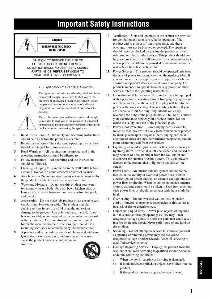
• Explanation of Graphical Symbols
The lightning flash with arrowhead symbol, within an equilateral triangle, is intended to alert you to the presence of uninsulated “dangerous voltage” within the product’s enclosure that may be of sufficient magnitude to constitute a risk of electric shock to persons.
The exclamation point within an equilateral triangle is intended to alert you to the presence of important operating and maintenance (servicing) instructions in the literature accompanying the appliance.
1 Read Instructions – All the safety and operating instructions should be read before the product is operated.
2 Retain Instructions – The safety and operating instructions should be retained for future reference.
3 Heed Warnings – All warnings on the product and in the operating instructions should be adhered to.
4 Follow Instructions – All operating and use instructions should be followed.
5 Cleaning – Unplug this product from the wall outlet before cleaning. Do not use liquid cleaners or aerosol cleaners.
6 Attachments – Do not use attachments not recommended by the product manufacturer as they may cause hazards.
7 Water and Moisture – Do not use this product near water – for example, near a bath tub, wash bowl, kitchen sink, or laundry tub; in a wet basement; or near a swimming pool; and the like.
8 Accessories – Do not place this product on an unstable cart, stand, tripod, bracket, or table. The product may fall, causing serious injury to a child or adult, and serious damage to the product. Use only with a cart, stand, tripod, bracket, or table recommended by the manufacturer, or sold with the product. Any mounting of the product should follow the manufacturer’s instructions, and should use a mounting accessory recommended by the manufacturer.
9 A product and cart combination should be moved with care. Quick stops, excessive force, and uneven surfaces may cause the product and cart combination to overturn.
10 Ventilation – Slots and openings in the cabinet are provided for ventilation and to ensure reliable operation of the product and to protect it from overheating, and these openings must not be blocked or covered. The openings should never be blocked by placing the product on a bed, sofa, rug, or other similar surface. This product should not be placed in a built-in installation such as a bookcase or rack unless proper ventilation is provided or the manufacturer’s instructions have been adhered to.
11 Power Sources – This product should be operated only from the type of power source indicated on the marking label. If you are not sure of the type of power supply to your home, consult your product dealer or local power company. For products intended to operate from battery power, or other sources, refer to the operating instructions.
12 Grounding or Polarization – This product may be equipped with a polarized alternating current line plug (a plug having one blade wider than the other). This plug will fit into the power outlet only one way. This is a safety feature. If you are unable to insert the plug fully into the outlet, try reversing the plug. If the plug should still fail to fit, contact your electrician to replace your obsolete outlet. Do not defeat the safety purpose of the polarized plug.
13 Power-Cord Protection – Power-supply cords should be routed so that they are not likely to be walked on or pinched by items placed upon or against them, paying particular attention to cords at plugs, convenience receptacles, and the point where they exit from the product.
14 Lightning – For added protection for this product during a lightning storm, or when it is left unattended and unused for long periods of time, unplug it from the wall outlet and disconnect the antenna or cable system. This will prevent damage to the product due to lightning and power-line surges.
15 Power Lines – An outside antenna system should not be located in the vicinity of overhead power lines or other electric light or power circuits, or where it can fall into such power lines or circuits. When installing an outside antenna system, extreme care should be taken to keep from touching such power lines or circuits as contact with them might be fatal.
16 Overloading – Do not overload wall outlets, extension cords, or integral convenience receptacles as this can result in a risk of fire or electric shock.
17 Object and Liquid Entry – Never push objects of any kind into this product through openings as they may touch dangerous voltage points or short-out parts that could result in a fire or electric shock. Never spill liquid of any kind on the product.
18 Servicing – Do not attempt to service this product yourself as opening or removing covers may expose you to dangerous voltage or other hazards. Refer all servicing to qualified service personnel.
19 Damage Requiring Service – Unplug this product from the wall outlet and refer servicing to qualified service personnel under the following conditions:
a) When the power-supply cord or plug is damaged,b) If liquid has been spilled, or objects have fallen into the
product,c) If the product has been exposed to rain or water,
Important Safety Instructions
CAUTION
CAUTION: TO REDUCE THE RISK OF ELECTRIC SHOCK, DO NOT REMOVE
COVER (OR BACK). NO USER-SERVICEABLE PARTS INSIDE. REFER SERVICING TO
QUALIFIED SERVICE PERSONNEL.
RISK OF ELECTRIC SHOCK DO NOT OPEN
i

Important Safety Instructions
d) If the product does not operate normally by following the operating instructions. Adjust only those controls that are covered by the operating instructions as an improper adjustment of other controls may result in damage and will often require extensive work by a qualified technician to restore the product to its normal operation,
e) If the product has been dropped or damaged in any way, and
f) When the product exhibits a distinct change in performance - this indicates a need for service.
20 Replacement Parts – When replacement parts are required, be sure the service technician has used replacement parts specified by the manufacturer or have the same characteristics as the original part. Unauthorized substitutions may result in fire, electric shock, or other hazards.
21 Safety Check – Upon completion of any service or repairs to this product, ask the service technician to perform safety checks to determine that the product is in proper operating condition.
22 Wall or Ceiling Mounting – This unit should be mounted to a wall or ceiling only as recommended by the manufacturer.
23 Heat – The product should be situated away from heat sources such as radiators, heat registers, stoves, or other products (including amplifiers) that produce heat.
COMPLIANCE INFORMATION STATEMENT(DECLARATION OF CONFORMITY PROCEDURE)
Responsible Party: Yamaha Electronics Corporation, U.S.A.
Address: 6660 Orangethorpe Avenue Buena Park, California 90620
Telephone: (714)522-9105Hours of operation: Monday through Friday
8 a.m. - 4 p.m. PST.
Type of Equipment: IP Audio Conference SystemModel Name: PJP-50R
This device complies with Part 15 of the FCC Rules.Operation is subject to the following two conditions:1) this device may not cause harmful interference, and2) this device must accept any interference received including interference that may cause undesired operation.See user manual instructions if interference to radioreception is suspected.
For residents in CaliforniaThis product contains a battery that contains perchlorate material.Perchlorate Material—special handling may apply. See www.dtsc.ca.gov/hazardouswaste/perchlorate.
FCC INFORMATION (for US customers)
1 IMPORTANT NOTICE: DO NOT MODIFY THIS UNIT!This product, when installed as indicated in the instructions contained in this manual, meets FCC requirements. Modifications not expressly approved by Yamaha may void your authority, granted by the FCC, to use the product.
2 IMPORTANT: When connecting this product to accessories and/or another product use only high quality shielded cables. Cable/s supplied with this product MUST be used. Follow all installation instructions. Failure to follow instructions could void your FCC authorization to use this product in the USA.
3 NOTE: This product has been tested and found to comply with the requirements listed in FCC Regulations, Part 15 for Class “A” digital devices. Compliance with these requirements provides a reasonable level of assurance that your use of this product in a commercial environment will not result in harmful interference with other electronic devices. However, operation of this product in a residential area is likely to cause interference in some form. In this case you, the user, bear the responsibility of correcting this condition.This product generates/uses radio frequencies and, if not installed and used according to the instructions found in the users manual, may cause interference
Compliance with FCC regulations does not guarantee that interference will not occur in all installations. If this product is found to be the source of interference, which can be determined by turning the product “OFF” and “ON”, please try to eliminate the problem by using one of the following measures:
Relocate either the product generating the interference or the device that is being affected by the interference.
Utilize power outlets that are on different branch (circuit breaker of fuse) circuits or install AC line filter/s.
In the case of radio or TV interference, relocate/reorient the antenna. If the antenna lead-in is 300 ohm ribbon lead, change the lead-in to coaxial type cable.
If these corrective measures do not produce satisfactory results, please contact your local retailer authorized to distribute this type of product. If you can not locate the appropriate retailer, please contact Yamaha Electronics Corp., U.S.A. 6660 Orangethorpe Ave., Buena Park, CA 90620.
The above statements apply ONLY to those products distributed by Yamaha Corporation of America or its subsidiaries.
ii
Important Safety InstructionsE
ng
lish
FCC INFORMATION (for US customers)
FOR CANADIAN CUSTOMERSThis product meets the applicable Industry Canada technical specifications. The Ringer Equivalence Number (REN) is an indication of the maximum number of devices allowed to be connected to a telephone interface. The termination on an interface may consist of any combination of devices subject only to the requirement that the sum of the RENs of all the devices does not exceed five.
Important safety instructions
When using your telephone equipment, basic safety precautions should always be followed to reduce the risk of fire, electric shock and injury to persons, including the following:1. Do not use this product near water for example, near a bath tub, wash bowl, kitchen sink, or laundry tub, in a wet basement, or
near a swimming pool.2. Avoid using a telephone (other than a cordless type) during an electrical storm. There may be a remote risk of electric shock
from lightning.3. Do not use the telephone to report a gas leak in the vicinity of the leak.
SAVE THESE INSTRUCTIONS
notice in order for you to make necessary modifications to maintain uninterrupted service.
If the PJP-50R causes harm to the telephone network, the telephone company will notify you in advance that temporary discontinuance of service may be required. But if advance notice isn’t practical, the telephone company will notify the customer as soon as possible. Also, you will be advised of your right to file a complaint with the FCC if you believe it is necessary.
If trouble is experienced with the PJP-50R, for repair or warranty information, please contact Yamaha Corporation. If the equipment is causing harm to the telephone network, the telephone company may request that you disconnect the equipment until the problem is resolved.
Ringer Equivalence Number (REN)The Ringer Equivalence Number (REN) is used to determine the number of devices that may be connected to a telephone line. Excessive RENs on a telephone line may result in the devices not ringing in response to an incoming call. In most but not all areas, the sum of RENs should not exceed five (5.0). To be certain of the number of devices that may be connected to a line, as determined by the total RENs, contact the local telephone company. For products approved after July 23, 2001, the REN for this product is part of the product identifier that has the format US:AAAEQ##TXXXX. The digits represented by ## are the REN without a decimal point (e.g., 03 is a REN of 0.3). For earlier products, the REN is separately shown on the label.
This equipment complies with Part 68 of the FCC rules and the requirement adopted by the ACTA. On the back of the main body of this equipment is a label that contains, among other information, a product identifier in the format US:AAAEQ##TXXXX. If requested, this number must be provided to the telephone company.
A plug and jack used to connect this equipment to the premises wiring and telephone network must comply with the applicable FCC Part 68 rules and requirements adopted by the ACTA. A compliant telephone cord and modular plug is provided with this product. It is designed to be connected to a compatible modular jack that is also compliant. See installation instructions for details.
Use the RJ-11C modular cable to connect this unit and telephone network.
Connect to party line service is subject to state tariffs. Contact the state public utility commission, public service commission or corporation commission for information.
If your home has specially wired alarm equipment connected to the telephone line, ensure the installation of this product does not disable your alarm equipment. If you have questions about what will disable alarm equipment, consult your telephone company or a qualified installer.
The telephone company may make changes in its facilities, equipment, operations or procedures that could affect the operation of the equipment. If this happens, the telephone company will provide advance
iii

iv
1 To assure the finest performance, please read this manual carefully. Keep it in a safe place for future reference.
2 Install this unit in a well ventilated, cool, dry, clean place with at least 10 cm on the top, 10 cm on the left and right, and 10 cm at the back of this unit — away from direct sunlight, heat sources, vibration, dust, moisture, and/or cold.
3 Locate this unit away from other electrical appliances, motors, or transformers to avoid humming sounds.
4 Do not expose this unit to sudden temperature changes from cold to hot, and do not locate this unit in an environment with high humidity (i.e. a room with a humidifier) to prevent condensation inside this unit, which may cause an electrical shock, fire, damage to this unit, and/or personal injury.
5 Avoid installing this unit where foreign object may fall onto this unit and/or this unit may be exposed to liquid dripping or splashing. On the top of this unit, do not place:– Other components, as they may cause damage and/or
discoloration on the surface of this unit.– Burning objects (i.e. candles), as they may cause fire, damage
to this unit, and/or personal injury.– Containers with liquid in them, as they may fall and liquid
may cause electrical shock to the user and/or damage to this unit.
6 Do not cover this unit with a newspaper, tablecloth, curtain, etc. in order not to obstruct heat radiation. If the temperature inside this unit rises, it may cause fire, damage to this unit, and/or personal injury.
7 Do not plug in this unit to a wall outlet until all connections are complete.
8 Do not operate this unit upside-down. It may overheat, possibly causing damage.
9 Do not use force on switches, knobs and/or cords.10 When disconnecting the power cable from the wall outlet, grasp
the plug; do not pull the cable.11 Do not clean this unit with chemical solvents; this might damage
the finish. Use a clean, dry cloth.12 Only voltage specified on this unit must be used. Using this unit
with a higher voltage than specified is dangerous and may cause fire, damage to this unit, and/or personal injury. YAMAHA will not be held responsible for any damage resulting from use of this unit with a voltage other than specified.
13 Do not attempt to modify or fix this unit. Contact qualified YAMAHA service personnel when any service is needed. The cabinet should never be opened for any reasons.
14 When not planning to use this unit for long periods of time (i.e. vacation), disconnect the AC power plug from the wall outlet.
15 Be sure to read the “Troubleshooting” section on common operating errors before concluding that this unit is faulty.
16 Before moving this unit, press and hold (Disconnect) to set this unit in standby mode, and disconnect the AC power plug from the wall outlet.
17 Condensation will form when the surrounding temperature changes suddenly. Disconnect the power cable from the outlet, then leave this unit alone.
18 When using this unit for a long time, this unit may become warm. Turn the power off, then leave this unit alone for cooling.
19 Install this unit near the wall outlet and where the AC power plug can be reached easily.
■ For U.K. customersIf the socket outlets in the home are not suitable for the plug sup-plied with this appliance, it should be cut off and an appropriate 3 pin plug fitted. For details, refer to the instructions described below.
The plug severed from the mains lead must be destroyed, as a plug with bared flexible cord is hazardous if engaged in a live socket outlet.
■ Special Instructions for U.K. Model
Caution: Read This Before Operating Your Unit.
This unit is not disconnected from the AC power source as long as it is connected to the AC wall outlet, even if this unit itself is turned off. This state is called the standby mode. In this state, this unit is designed to consume a very small quantity of power.
FOR CANADIAN CUSTOMERSTo prevent electric shock, match wide blade of plug to wide slot and fully insert.This Class A digital apparatus complies with Canadian ICES-003.
WARNINGTO REDUCE THE RISK OF FIRE OR ELECTRIC SHOCK, DO NOT EXPOSE THIS UNIT TO RAIN OR MOISTURE.
WARNINGTHE POWER SUPPLY CABLE OF THIS UNIT MUST BE CONNECTED TO THE MAIN SOCKET OUTLET VIA A PROTECTIVE EARTHING CONNECTION.
WARNINGThis is a class A product. In a domestic environment this product may cause radio interference in which case the user may be required to take adequate measures.
Note
WARNING-THIS APPARATUS MUST BE EARTHED.IMPORTANTTHE WIRES IN THIS MAINS LEAD ARE COLOURED IN ACCORDANCE WITH THE FOLLOWING CODE:
GREEN-AND-YELLOW:EARTHBLUE:NEUTRALBROWN:LIVE
As the colours of the wires in the mains lead of this appa-ratus may not correspond with the coloured markings identifying the terminals in your plug, proceed as follows:The wire which is coloured GREEN-AND-YELLOW must be connected to the terminal in the plug which is marked by the letter E or by the safety earth symbol or coloured GREEN or GREEN-and-YELLOW.The wire which is coloured BLUE must be connected to the ter-minal which is marked with the letter N or coloured BLACK.The wire which is coloured BROWN must be connected to the terminal which is marked with the letter L or coloured RED.

BA
SIC
CA
LL
O
PE
RA
TIO
NS
INT
RO
DU
CT
ION
AD
DIT
ION
AL
IN
FO
RM
AT
ION
En
glish
Features .................................................................. 2About this Manual ................................................. 3
Supplied Accessories ................................................ 3Controls and Functions ......................................... 4
Communication through IP Network .................. 7Calling another party ................................................ 7Calling another party using the address book ........... 8Calling another party using the call history .............. 9Answering a Call ...................................................... 9
Operations during Communication through IP Network ........................................ 10Adjusting the speaker volume ................................ 10Changing the microphone and speaker settings ...... 10
Talking with Multiple Locations ........................ 12Display and speaker output
during multiple connections ............................... 13Communication through Telephone Circuit ..... 14
Calling another party .............................................. 14Calling another party using the address book ......... 15Calling another party using the call history ............ 16Answering a Call .................................................... 16
Operations during Communication through Telephone Circuit ............................. 17Adjusting the speaker volume ................................ 17Changing the microphone and speaker settings ...... 17Sending tone signals ............................................... 19Transferring a call (Telephone circuit only) ........... 19
Troubleshooting ................................................... 20Q1: LED indicators do not light up ........................ 20Q2: A call cannot be made ...................................... 21Q3: Other problems ................................................ 22
Setup guide (a separate manual)
Features .................................................................. 2About this Manual ................................................. 3
Supplied Accessories ................................................ 3
Preparation Procedure .......................................... 4Step 1: Connecting this unit ...................................... 5Step 2: Registering the settings of this unit .............. 6Step 3: Installing this unit in the conference room .... 11
Configuring the Settings ......................................12Configuring the settings using the keys
on this unit .......................................................... 12Configuring the settings using the Web menu ........ 13
Setting the Menu List ...........................................14Registering the IP network information ................. 14Setup of telephone functions .................................. 15Configuring the sound settings ............................... 16Configuring the general settings ............................. 20Call history management ........................................ 21Setting the password ............................................... 21Calling a ProjectPhone system
in the same subnet .............................................. 21Setting the Date and Time ...................................22
Setting the date and time manually ......................... 22Setting the date and time using the SNTP server ... 22
Editing the Address Book ....................................23Registering a new address ...................................... 23Editing an existing address ..................................... 23
Using the SIP Server ............................................24Registering the SIP server information .................. 24Notes on SIP server operation ................................ 24Display in SIP server operation .............................. 25
Hierarchical Connection of Multiple ProjectPhone (Cascade Connection) ..............26What is a cascade connection? ............................... 26Configuring the cascade settings ............................ 27Communication using a cascade connection .......... 28Display in cascade connection ................................ 28
Interlocked Connection of ProjectPhone Systems ......................................29
Connection Using Audio Connection Cables .....30Connecting with a PC or TV conference system .... 30Connection of the headphone output and
microphone input terminals ................................ 31Setting of PC ........................................................... 32
Updating the Firmware .......................................34Software Licensing Agreement .............................. 34Updating the firmware automatically ..................... 35Updating the firmware manually ............................ 36
Troubleshooting ....................................................38Q1: LED indicators do not light up ........................ 38Q2: Web menu setting is not available ................... 39Q3: A call cannot be made ...................................... 40Q4: Other problems ................................................ 41
Resetting this Unit ................................................42Obtaining the Setting Information
for Support on this Unit ...................................44Obtaining the setting information ........................... 44
Confirming the System Log Message of This Unit (Syslog) .........................................45
Specifications ........................................................46Notes on Transferring/Disposing this Unit ........47
Contents
INTRODUCTION
BASIC CALL OPERATIONS
ADDITIONAL INFORMATION
INTRODUCTION
PREPARATION
CONFIGURATIONS
ADDITIONAL INFORMATION
1
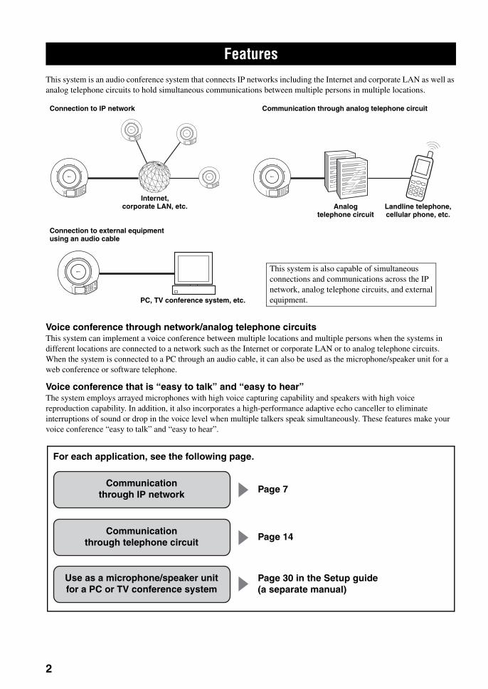
This system is an audio conference system that connects IP networks including the Internet and corporate LAN as well as analog telephone circuits to hold simultaneous communications between multiple persons in multiple locations.
Voice conference through network/analog telephone circuitsThis system can implement a voice conference between multiple locations and multiple persons when the systems in different locations are connected to a network such as the Internet or corporate LAN or to analog telephone circuits. When the system is connected to a PC through an audio cable, it can also be used as the microphone/speaker unit for a web conference or software telephone.
Voice conference that is “easy to talk” and “easy to hear”The system employs arrayed microphones with high voice capturing capability and speakers with high voice reproduction capability. In addition, it also incorporates a high-performance adaptive echo canceller to eliminate interruptions of sound or drop in the voice level when multiple talkers speak simultaneously. These features make your voice conference “easy to talk” and “easy to hear”.
Features
Analog telephone circuit
Connection to IP network Communication through analog telephone circuit
Connection to external equipment using an audio cable
Internet, corporate LAN, etc. Landline telephone,
cellular phone, etc.
PC, TV conference system, etc.
This system is also capable of simultaneous connections and communications across the IP network, analog telephone circuits, and external equipment.
Communication through IP network
Use as a microphone/speaker unitfor a PC or TV conference system
Communication through telephone circuit
Page 7
Page 14
Page 30 in the Setup guide (a separate manual)
For each application, see the following page.
2
En
glish
FeaturesIN
TR
OD
UC
TIO
N
• In this manual, the names of the following products are denoted as follows.– Yamaha PJP-50R: this unit– Microsoft® Windows®: Windows– Microsoft® Windows XP®: Windows XP– 10BASE-T (100BASE-TX) cable: LAN cable
• The IP addresses, domain names, and URL names mentioned in the setting examples are used merely for the purpose of ease of explanation. When you perform the actual settings of this unit, be sure to set the addresses and names according to the actual configuration of your network.
• Detailed knowledge on the Internet and network may be required to utilize this unit at its full performance. As the provided manual does not give detailed technical information, please also refer to commercially available books as required.
• This manual is printed prior to production. Design and specifications are subject to change in part as a result of improvements, etc. If there are differences between the manual and the product, the product has priority.
■ Check the latest informationThis manual has been compiled based on the latest version of the firmware as of October, 2007. Note that the actual operations of the system may differ from the information given in this manual due to the addition of new functions or improvement of existing functions as a result of upgrading of the firmware revision.
For the latest information and firmware, please visit the ProjectPhone support webpage of the following address. This page also gives explanations on details of the latest functions.
http://www.yamaha.co.jp/english/product/projectphone/
For the revision upgrading procedure, refer to “Updating the Firmware” (page 34) in the “Setup guide” (a separate manual).
■ About trademarks• Ethernet is a registered trademark of Xerox Corporation.• Microsoft, Windows and Microsoft Excel are registered trademarks of Microsoft Corporation in United States and
other countries.• Adobe and Acrobat are registered trademarks of Adobe Systems, Inc.
This product includes the following accessories. Before connecting this system, make sure you received all of the following parts.
• AC adapter (PJP-PS01) x 1• Power cable x 1• LAN cable x 1• Modular telephone cable x 1• Owner’s Manual (Basic operation guide) x 1• Owner’s Manual (Setup guide) x 1• Warranty card x 1
About this Manual
Supplied Accessories
3

CONTROLS AND FUNCTIONS
■ Top panel
1 Microphone indicatorsA blue LED lights to indicate the audio pick up area.
2 Arrayed microphonesThe 16 microphones on the top panel capture the voices of the talkers.
3 (Connect) keyPress the key when placing a call to the designated destination or receiving an incoming call.
4 (Disconnect) key/STANDBY key• Press the key to end a call. Pressing the key when there
is an incoming call through IP network rejects the call.• Press and hold to set the system to the standby mode.
yPress any key of the system to exit the standby mode.
5 DisplayThe LCD shows the current status of this unit (page 6).
6 (Cancel) keyPress the key to cancel a setting without saving it or to return to the previous page.
7 / (Up/Down) keysPress either key to select a setting item or move the cursor up or down.
8 (Enter) key/HOOK key• Press the key to enter a setting.• Press the key to transfer a telephone call during it.
9 Numeric keysPress the keys to enter the numbers of the call destination or IP address.
0 MIC MUTE keyPress the key to temporarily defeat (mute) the microphones of this unit. The key lights in orange when muted.Pressing the key when the microphones are muted releases the mute and turns the LED off.
A VOL +/– keyPress either key to adjust the speaker volume. Holding either key increases or decreases the volume continuously.
Controls and Functions
MIC MUTE
/ STANDBY
HOOK
VOL
4
70
8
5
26
3
9
#
1
2
3 4 5 6 78 0 A9
1
4

Controls and FunctionsIN
TR
OD
UC
TIO
NE
ng
lish
■ Side panel
1 LINE portConnect an analog telephone circuit.
2 LAN portConnect a LAN cable for connection to network equipment such as a PC, router, or hub. The LED lights up when the port is connected to a network and blinks according to the communication status.
3 DC IN 12V terminalConnect the provided AC adapter.
4 AUDIO IN terminalConnect to the line output terminal or the headphone output terminal of an audio equipment or PC.
5 AUDIO OUT terminalConnect to the line input terminal or the microphone input terminal of an audio equipment or PC.
■ Bottom panel1 Serial labelThe label carries the following information.• MODEL NO.: Model number of this unit.• SER.: Serial number for use in management/
distinction of this unit.• MAC ADDRESS: MAC address of this unit.• Registration NO. (U.S. and Canada models only):
FCC (U.S.) and Industry Canada (IC) registration number.
• IC REN (U.S. and Canada models only): Ringer Equivalence Number (REN) of this unit.
2 Arrayed speakersThe four arrayed speakers on the bottom panel for use in output of the audio from other parties communicating with this unit.
3 AdjusterIf this system is unstable because the tabletop or desktop is not flat, adjust the foot height using the adjuster.
LINE LAN DC IN 12V IN AUDIO OUT
+-
1 2 3 4 5
MODEL NO. PJP-50RRegistration NO. US : A6RTE00BPJP50RIC Registration NO. IC : 740B-PJP50RIC REN : 0.1
YAMAHA CORPORATIONMADE IN JAPAN12VAC ADAPTOR : PJP-PS01
THIS DEVICE COMPLIES WITH PART I5 OF THE FCC RULES. OPERATION IS SUBJECT TO THE FOLLOWING TWO CONDITONS:(1) THIS DEVICE MAY NOT CAUSE HARMFUL INTERFERENCE, AND (2) THIS DEVICE MUST ACCEPT ANY INTERFERENCE RECEIVED,INCLUDING INTERFERENCE THAT MAY CAUSE INDESIRED OPERATION.
THIS CLASS A DIGITAL APPARATUS COMPLIES WITH CANADIAN ICES-003.CET APPAREIL NUMÉRIQUE DE LA CLASSE A EST CONFORME À LA NORME NMB-003 DU CANADA.
PJP-50R
1 2 3
2
5
Controls and Functions
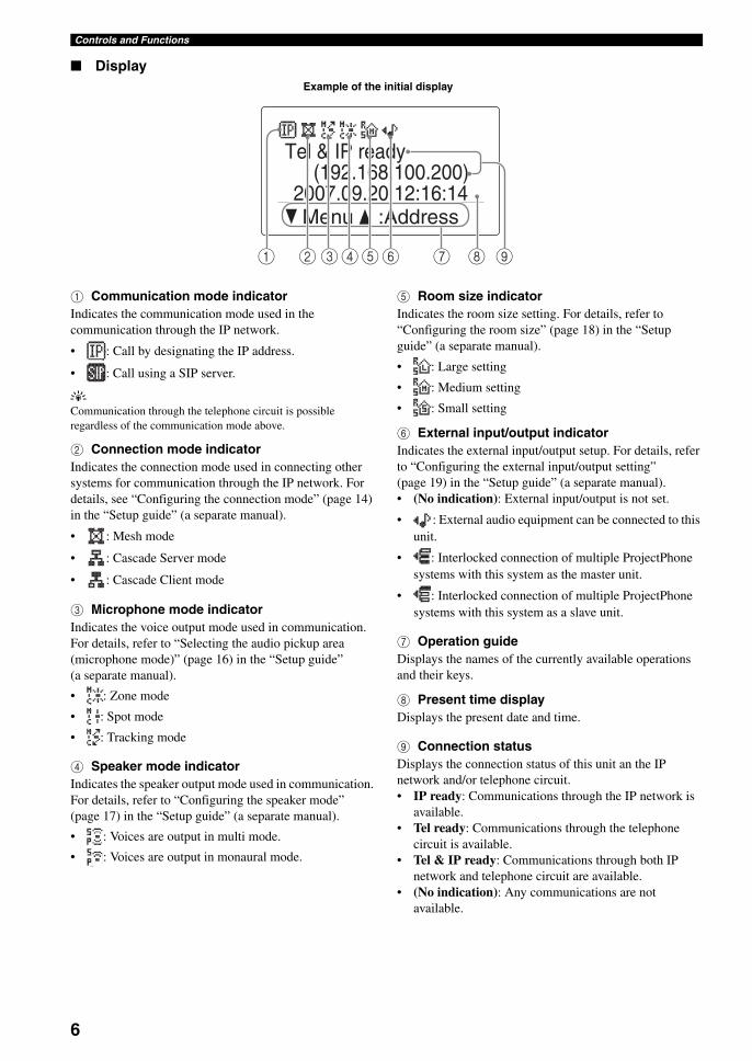
■ Display
1 Communication mode indicatorIndicates the communication mode used in the communication through the IP network.
• : Call by designating the IP address.
• : Call using a SIP server.
yCommunication through the telephone circuit is possible regardless of the communication mode above.
2 Connection mode indicatorIndicates the connection mode used in connecting other systems for communication through the IP network. For details, see “Configuring the connection mode” (page 14) in the “Setup guide” (a separate manual).
• : Mesh mode
• : Cascade Server mode
• : Cascade Client mode
3 Microphone mode indicatorIndicates the voice output mode used in communication. For details, refer to “Selecting the audio pickup area (microphone mode)” (page 16) in the “Setup guide”(a separate manual).
• : Zone mode
• : Spot mode
• : Tracking mode
4 Speaker mode indicatorIndicates the speaker output mode used in communication. For details, refer to “Configuring the speaker mode” (page 17) in the “Setup guide” (a separate manual).
• : Voices are output in multi mode.
• : Voices are output in monaural mode.
5 Room size indicatorIndicates the room size setting. For details, refer to “Configuring the room size” (page 18) in the “Setup guide” (a separate manual).
• : Large setting
• : Medium setting
• : Small setting
6 External input/output indicatorIndicates the external input/output setup. For details, refer to “Configuring the external input/output setting” (page 19) in the “Setup guide” (a separate manual).• (No indication): External input/output is not set.
• : External audio equipment can be connected to this unit.
• : Interlocked connection of multiple ProjectPhone systems with this system as the master unit.
• : Interlocked connection of multiple ProjectPhone systems with this system as a slave unit.
7 Operation guideDisplays the names of the currently available operations and their keys.
8 Present time displayDisplays the present date and time.
9 Connection statusDisplays the connection status of this unit an the IP network and/or telephone circuit.• IP ready: Communications through the IP network is
available.• Tel ready: Communications through the telephone
circuit is available.• Tel & IP ready: Communications through both IP
network and telephone circuit are available.• (No indication): Any communications are not
available.
(192.168.100.200)
Menu :Address
Tel & IP ready
2007.09.20 12:16:14
1 23456 7 8 9
Example of the initial display
6

Communication through IP NetworkB
AS
IC C
AL
L
OP
ER
AT
ION
SE
ng
lish
To place a call to another party, enter its IP address.
Before using the functions of this system, it is necessary to install, connect, and set up the system. For details, refer to the “Setup guide” (a separate manual).
1 Press repeatedly until the initial display appears.Make sure that “Tel & IP ready” or “IP ready” appears in the display.
2 Use the numeric keys to enter the IP address of the destination.Enter “*” in place of “. (period)”.Example: 192.168.100.10 → 192*168*100*10
If you make an entry mistake, press to delete the numbers, and then enter the correct numbers by using the numeric keys again.
3 Press .The calling display appears.
Communication through IP Network
Calling another party
CAUTION
HOOK
/ STANDBY
VOL
MIC MUTE
4
70
8
5
26
3
9
#
1
MIC MUTE
Numeric keysVOL +/–
(192.168.100.200)
Menu :Address2007.09.20 12:16:14
Tel & IP ready
[ ] [#] 0-9
192 168 0Number
[ ] [#]
000.000.000.000^
192.168.0.10:Cancel
7

Communication through IP Network
The following display appears if the call is connected and conversation becomes available.
yPress during communication to view the setting of the system as shown below.
• Do not disconnect the LAN cable or power cable during a call. Doing so may cause malfunction.
• If the call failed, check the following:–The destination unit is turned on.–This unit is connected to the network properly.–Check the call history to identify the cause of the trouble.–See “Q2: A call cannot be made” (page 21).
4 To disconnect the call when the conference is complete, press .
Follow the procedure below to call another party registered in the address book.
yTo use this function, it is required to use the PC for registering the addresses of the locations to be called in the Address Book. See “Editing the Address Book” (page 23) in the “Setup guide” (a separate manual) for details.
1 Press repeatedly until the initial display appears.
2 Press .The Address Book display appears.
• : Telephone numbers are registered.
• : IP extension numbers are registered.
• : IP addresses are registered.
• : SIP addresses are registered.
3 Press or to select the destination, and then press .The calling display appears.
The registered name of the destination appears if the call is connected and conversation becomes available.
yIf you know the registration number of the destination in the address book, you can call the address by pressing the numeric keys. After entering “9#” (prefix), enter the registration number of the desired address and then
press .
Notes
192.168.0.10
Menu :Address
IP address of the destination
IP: 192.168.100.200
Calling another party using the address book
Branch BBranch AHeadquarter
Address Book
Branch BBranch AHeadquarter
Address Book
Branch AHeadquarterHeadquarterHeadquarter
:Cancel
8

Communication through IP NetworkB
AS
IC C
AL
L
OP
ER
AT
ION
SE
ng
lish
Follow the procedure below to call another party by referring to the history of past outgoing or incoming calls.
If the destination obtains the IP address from a DHCP server, its IP address may have changed from the last call. If your call cannot reach the destination unit, check the latest IP address configured at the destination.
1 Press repeatedly until the initial display appears.
2 Press .The menu screen appears.
3 Press or to select “Call History”, and then press .The “Call History” menu appears.
• : Indicates an outgoing call.
• : Indicates an incoming call.
• : Indicates a missed call.
• : Indicates an automatic incoming/outgoing call.
4 Press or to select the destination, and then press .The calling display appears.
The IP addresses of this unit and destination appear if the call is connected and conversation becomes available.
yIf a destination is already registered in the address book, the name registered for the destination is displayed instead of the IP address.
Follow the procedure below to answer a call from another party.
1 When an incoming call is received, press .When there is an incoming call, the back light of the display lights up, and the ringing tone for the IP network connection is generated.The IP address of the destination appears in the display.
y• If the call is made by the party which is already registered
in the address book, the name registered for this unit is displayed instead of the IP address.
• To deny a call, press when the incoming call is received.
2 To disconnect the call when the conference is complete, press .
Calling another party using the call history
Note
3. Online2. Call History1. Settings
Menu
PhoneHeadquarterHeadquarter
Call History
Answering a Call
Branch AHeadquarterHeadquarter
Call History
Headquarter:Cancel
Menu :Address
(192.168.100.200)2007.09.20 12:16:14
Tel & IP ready192.168.0.10
9

Operations during Communication through IP Network
Press VOL + or – during communication to adjust the speaker output volume.
■ Muting the microphone input temporarily
If the persons in your location want to discuss in private, press MIC MUTE. The microphones are switched off, and the LED of MIC MUTE is lit, so the persons in other locations cannot hear what you are talking.To cancel the microphone muting, press MIC MUTE to turn the LED off.
This unit does not mute the sounds input at the component connected to the AUDIO IN jack.
The microphone and speaker settings can be modified in the middle of communication.
1 Press during communication.The menu screen appears.
2 Press or to select “Settings”, and then press .The “Sound Settings” menu appears.
3 Press to select “Sound Settings”, and then press or to select a menu item to be set.
y• is used to select a menu item.
• After completing the setting, press repeatedly until the display during communication is recalled.
■ Selecting the audio pickup area (microphone mode)
You can select the audio pickup area of the microphone during a call.
yYou can display the “Microphone Mode” menu by holding down
in the initial display or calling display.
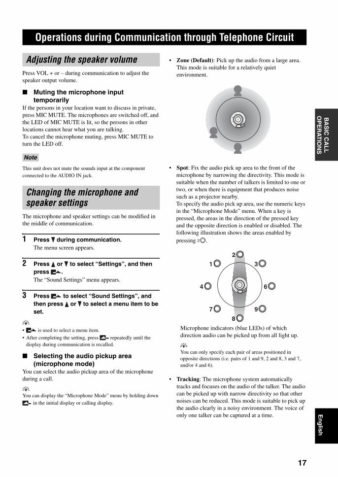
• Zone (Default): Pick up the audio from a large area. This mode is suitable for a relatively quiet environment.
• Spot: Fix the audio pick up area to the front of the microphone by narrowing the directivity. This mode is suitable when the number of talkers is limited to one or two, or when there is equipment that produces noise such as a projector nearby.To specify the audio pick up area, use the numeric keys in the “Microphone Mode” menu. When a key is pressed, the areas in the direction of the pressed key and the opposite direction is enabled or disabled. The following illustration shows the areas enabled by pressing .
Microphone indicators (blue LEDs) of which direction audio can be picked up from all light up.
yYou can only specify each pair of areas positioned in opposite directions (i.e. pairs of 1 and 9, 2 and 8, 3 and 7, and/or 4 and 6).
• Tracking: The microphone system automatically tracks and focuses on the audio of the talker. The audio can be picked up with narrow directivity so that other noises can be reduced. This mode is suitable to pick up the audio clearly in a noisy environment. The voice of only one talker can be captured at a time.
Operations during Communication through IP Network
Adjusting the speaker volume
Note
Changing the microphone and speaker settings
MIC MUTE
VOL
4
70
8
5
26
3
9
#
1
/STANDBY
HOOK
2
MIC MUTE
VOL
4
70
8
5
26
3
9
#
1
HOOK
1
2
3
6
9
8
7
4/STANDBY
10
Operations during Communication through IP NetworkB
AS
IC C
AL
L
OP
ER
AT
ION
SE
ng
lish
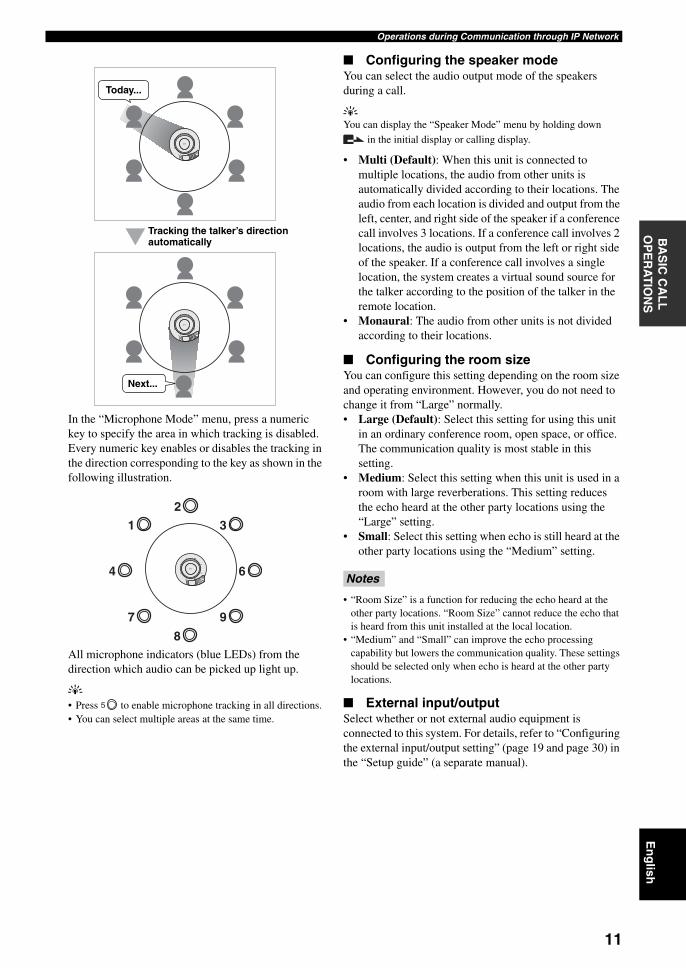
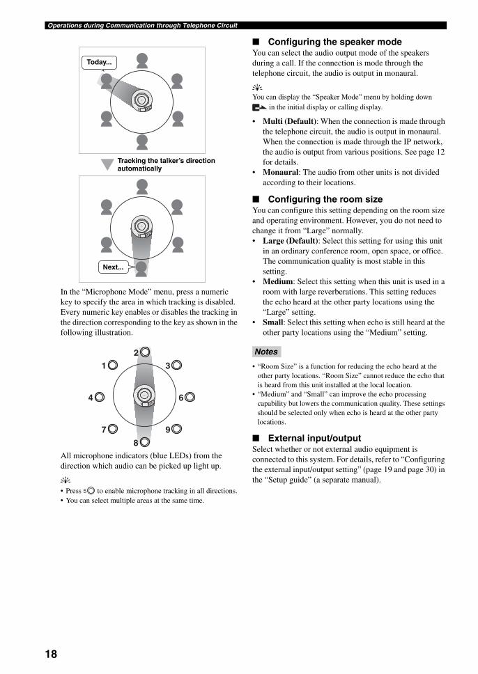
In the “Microphone Mode” menu, press a numeric key to specify the area in which tracking is disabled. Every numeric key enables or disables the tracking in the direction corresponding to the key as shown in the following illustration.
All microphone indicators (blue LEDs) from the direction which audio can be picked up light up.
y• Press to enable microphone tracking in all directions.• You can select multiple areas at the same time.
■ Configuring the speaker modeYou can select the audio output mode of the speakers during a call.
yYou can display the “Speaker Mode” menu by holding down
in the initial display or calling display.
• Multi (Default): When this unit is connected to multiple locations, the audio from other units is automatically divided according to their locations. The audio from each location is divided and output from the left, center, and right side of the speaker if a conference call involves 3 locations. If a conference call involves 2 locations, the audio is output from the left or right side of the speaker. If a conference call involves a single location, the system creates a virtual sound source for the talker according to the position of the talker in the remote location.
• Monaural: The audio from other units is not divided according to their locations.
■ Configuring the room sizeYou can configure this setting depending on the room size and operating environment. However, you do not need to change it from “Large” normally.• Large (Default): Select this setting for using this unit
in an ordinary conference room, open space, or office. The communication quality is most stable in this setting.
• Medium: Select this setting when this unit is used in a room with large reverberations. This setting reduces the echo heard at the other party locations using the “Large” setting.
• Small: Select this setting when echo is still heard at the other party locations using the “Medium” setting.
• “Room Size” is a function for reducing the echo heard at the other party locations. “Room Size” cannot reduce the echo that is heard from this unit installed at the local location.
• “Medium” and “Small” can improve the echo processing capability but lowers the communication quality. These settings should be selected only when echo is heard at the other party locations.
■ External input/outputSelect whether or not external audio equipment is connected to this system. For details, refer to “Configuring the external input/output setting” (page 19 and page 30) in the “Setup guide” (a separate manual).
MIC MUTE
VOL
4
70
8
5
26
3
9
#
1
MIC MUTE
VOL
4
70
8
5
26
3
9
#
1
Tracking the talker’s direction automatically
Today...
Next...
MIC MUTE
VOL
4
70
8
5
26
3
9
#
1
1
2
3
6
9
8
7
4/STANDBY
HOOK
5
Notes
11

Talking with Multiple Locations
This system enables simultaneous talk between up to four locations (with the mesh connection) through an IP network. It is also possible to call additional locations as required during a call. To hold a communication between multiple locations, begin a call with a single location and then call other required locations.
y• Communication between up to eight locations is also possible
by using the cascade connection. For details, refer to “Hierarchical Connection of Multiple ProjectPhone (Cascade Connection)” (page 26) in the “Setup guide” (a separate manual).
• After connecting the locations with mesh connection through the IP network, each location can call an additional location through the telephone circuit.
■ To call another location during a callRefer to one of the following procedure during a call.
– Calling another unit by specifying an IP address (page 7)
– Calling another unit by specifying a telephone number (page 14)
– Calling another unit using the address book (page 8)– Calling another unit using the call history (page 9)
The new location is added to the ongoing conference.
■ To answer a call during a callRefer to the procedure in “Answering a Call” (page 9).The new location is added to the ongoing conference.
Talking with Multiple Locations
12
3
45
6
78
9
0
MIC MUTE
VOL
12
3
45
6
78
9
0
MIC MUTE
VOL
12
3
45
6
78
9
0
MIC MUTE
VOL
12
3
45
6
78
9
0
MIC MUTE
VOL
12
3
45
6
78
9
0
MIC MUTE
VOL
12
3
45
6
78
9
0
MIC MUTE
VOL
Connecting more than two locations
Call another location during a call
Connecting
Connecting
Connecting
Headquarter Branch A
Branch BMaking a call
Headquarter Branch A
Branch B
12
Talking with Multiple LocationsB
AS
IC C
AL
L
OP
ER
AT
ION
SE
ng
lish
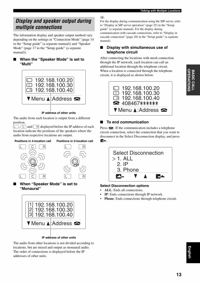
The information display and speaker output method vary depending on the settings in “Connection Mode” (page 14 in the “Setup guide” (a separate manual)) and “Speaker Mode” (page 17 in the “Setup guide” (a separate manual)).
■ When the “Speaker Mode” is set to “Multi”
The audio from each location is output from a different position.
, and displayed before the IP address of each location indicate the positions of the speakers where the audio from respective locations are output.
■ When “Speaker Mode” is set to “Monaural”
The audio from other locations is not divided according to locations, but are mixed and output as monaural audio.The order of connections is displayed before the IP addresses of other units.
yFor the display during communication using the SIP server, refer to “Display in SIP server operation” (page 25) in the “Setup guide” (a separate manual). For the display during communication with cascade connections, refer to “Display in cascade connection” (page 28) in the “Setup guide” (a separate manual).
■ Display with simultaneous use of telephone circuit
After connecting the locations with mesh connection through the IP network, each location can call an additional location through the telephone circuit.When a location is connected through the telephone circuit, it is displayed as shown below.
■ To end communicationPress . If the communication includes a telephone circuit connection, select the connection that you want to disconnect in the Select Disconnection display, and press
.
Select Disconnection options• ALL: Ends all connections.• IP: Ends connections through IP network.• Phone: Ends connections through telephone circuit.
Display and speaker output during multiple connections
192.168.100.20192.168.100.30192.168.100.40
Menu :Address
IP address of other units
MIC MUTE
VOL
4
70
8
5
26
3
9
#
1MIC MUTE
VOL
4
70
8
5
26
3
9
#
1
Positions in 4-location call Positions in 3-location call
192.168.100.20[1][2][3]
192.168.100.30192.168.100.40
Menu :Address
IP address of other units
192.168.100.20192.168.100.30192.168.100.40408467
Menu :Address
3. Phone2. IP1. ALL
Select Disconnection
13

Communication through Telephone Circuit
To place a call to another party, enter its telephone number.
• Before using the functions of this system, it is necessary to install, connect, and set up the system. For details, refer to the “Setup guide” (a separate manual).
• Before using this function, it is necessary to set the country code. For details, refer to “Setting the country using the telephone function” (page 16) in the “Setup guide” (a separate manual).
1 Press repeatedly until the initial display appears.Make sure that “Tel & IP ready”or “Tel ready” appears in the display.
2 Enter the telephone number of the called location with the numeric keys.
If you make an entry mistake, press to delete the numbers, and then enter the correct numbers by using the numeric keys again.
3 Press .The calling display appears.
Communication through Telephone Circuit
Calling another party
CAUTION
HOOK
/ STANDBY
VOL
MIC MUTE
4
70
8
5
26
3
9
#
1
MIC MUTE
Numeric keysVOL +/–
Menu :Address2007.09.20 12:16:14
Tel ready[ ] [#] 0-9
4084Number
[ ] [#]
^
408467:Cancel
14

Communication through Telephone CircuitB
AS
IC C
AL
L
OP
ER
AT
ION
SE
ng
lish
The following display appears if the call is connected and conversation becomes available.
yPress during communication to view the setting of the system as shown below.
• Do not disconnect the modular telephone cable or power cable during a call. Doing so may cause malfunction.
• If the call failed, check the following:–The destination unit is turned on.–This unit is connected to the network properly.–Check the call history to identify the cause of the trouble.–See “Q2: A call cannot be made” (page 21).
4 To disconnect the call when the conference is complete, press .
Follow the procedure below to call another party registered in the address book.
yTo use this function, it is required to use the PC for registering the telephone numbers of the locations to be called in the Address Book. For details refer to “Editing the Address Book” (page 23) in the “Setup guide” (a separate manual).
1 Press repeatedly until the initial display appears.
2 Press .The Address Book display appears.
3 Press or to select the destination, and then press .The calling display appears.
The registered name of the destination appears if the call is connected and conversation becomes available.
yIf you know the registration number of the destination in the address book, you can call the address by pressing the numeric keys. After entering “9#” (prefix), enter the registration number of the desired address and then
press .
Notes
408467
Menu :Address
Tel. No. of other system
IP: 192.168.100.200
Calling another party using the address book
Branch BBranch AHeadquarter
Address Book
Branch BBranch AHeadquarter
Address Book
Branch AHeadquarterHeadquarter
Branch B:Cancel
15

Communication through Telephone Circuit
Follow the procedure below to call another party by referring to the history of past outgoing or incoming calls.
1 Press repeatedly until the initial display appears.
2 Press .The menu screen appears.
3 Press or to select “2. Call History”, and then press .The “Call History” menu appears.
• : Indicates an outgoing call.
• : Indicates an incoming call.
• : Indicates a missed call.
• : Indicates an automatic incoming/outgoing call.
4 Press or to select the destination, and then press .The calling display appears.
The phone numbers of this unit and destination unit appear if the call is connected and conversation becomes available.
yIf a destination is already registered in the address book, the name registered for the destination is displayed instead of the phone numbers.
Follow the procedure below to answer a call from another party.
1 When an incoming call is received, press .When there is an incoming call, the back light of the display lights up, and the telephone ringing tone is generated.
yWhen receiving an extension call, the ringing tone for the extention call is generated.
2 To disconnect the call when the conference is complete, press .
Calling another party using the call history
3. Online2. Call History1. Settings
Menu
PhoneHeadquarterHeadquarter
Call History
Answering a Call
Branch AHeadquarterHeadquarter
Call History
:CancelHeadquarter
Menu :Address
(192.168.100.200)2007.09.20 12:16:14
Tel & IP readyPhone
16
Operations during Communication through Telephone CircuitB
AS
IC C
AL
L
OP
ER
AT
ION
SE
ng
lish
Press VOL + or – during communication to adjust the speaker output volume.
■ Muting the microphone input temporarily
If the persons in your location want to discuss in private, press MIC MUTE. The microphones are switched off, and the LED of MIC MUTE is lit, so the persons in other locations cannot hear what you are talking.To cancel the microphone muting, press MIC MUTE to turn the LED off.
This unit does not mute the sounds input at the component connected to the AUDIO IN jack.
The microphone and speaker settings can be modified in the middle of communication.
1 Press during communication.The menu screen appears.
2 Press or to select “Settings”, and then press .The “Sound Settings” menu appears.
3 Press to select “Sound Settings”, and then press or to select a menu item to be set.
y• is used to select a menu item.
• After completing the setting, press repeatedly until the display during communication is recalled.
■ Selecting the audio pickup area (microphone mode)
You can select the audio pickup area of the microphone during a call.
yYou can display the “Microphone Mode” menu by holding down
in the initial display or calling display.
• Zone (Default): Pick up the audio from a large area. This mode is suitable for a relatively quiet environment.
• Spot: Fix the audio pick up area to the front of the microphone by narrowing the directivity. This mode is suitable when the number of talkers is limited to one or two, or when there is equipment that produces noise such as a projector nearby.To specify the audio pick up area, use the numeric keys in the “Microphone Mode” menu. When a key is pressed, the areas in the direction of the pressed key and the opposite direction is enabled or disabled. The following illustration shows the areas enabled by pressing .
Microphone indicators (blue LEDs) of which direction audio can be picked up from all light up.
yYou can only specify each pair of areas positioned in opposite directions (i.e. pairs of 1 and 9, 2 and 8, 3 and 7, and/or 4 and 6).
• Tracking: The microphone system automatically tracks and focuses on the audio of the talker. The audio can be picked up with narrow directivity so that other noises can be reduced. This mode is suitable to pick up the audio clearly in a noisy environment. The voice of only one talker can be captured at a time.
Operations during Communication through Telephone Circuit
Adjusting the speaker volume
Note
Changing the microphone and speaker settings
MIC MUTE
VOL
4
70
8
5
26
3
9
#
1
/STANDBY
HOOK
2
MIC MUTE
VOL
4
70
8
5
26
3
9
#
1
HOOK
1
2
3
6
9
8
7
4/STANDBY
17
Operations during Communication through Telephone Circuit
In the “Microphone Mode” menu, press a numeric key to specify the area in which tracking is disabled. Every numeric key enables or disables the tracking in the direction corresponding to the key as shown in the following illustration.
All microphone indicators (blue LEDs) from the direction which audio can be picked up light up.
y• Press to enable microphone tracking in all directions.• You can select multiple areas at the same time.
■ Configuring the speaker modeYou can select the audio output mode of the speakers during a call. If the connection is mode through the telephone circuit, the audio is output in monaural.
yYou can display the “Speaker Mode” menu by holding down
in the initial display or calling display.
• Multi (Default): When the connection is made through the telephone circuit, the audio is output in monaural. When the connection is made through the IP network, the audio is output from various positions. See page 12 for details.
• Monaural: The audio from other units is not divided according to their locations.
■ Configuring the room sizeYou can configure this setting depending on the room size and operating environment. However, you do not need to change it from “Large” normally.• Large (Default): Select this setting for using this unit
in an ordinary conference room, open space, or office. The communication quality is most stable in this setting.
• Medium: Select this setting when this unit is used in a room with large reverberations. This setting reduces the echo heard at the other party locations using the “Large” setting.
• Small: Select this setting when echo is still heard at the other party locations using the “Medium” setting.
• “Room Size” is a function for reducing the echo heard at the other party locations. “Room Size” cannot reduce the echo that is heard from this unit installed at the local location.
• “Medium” and “Small” can improve the echo processing capability but lowers the communication quality. These settings should be selected only when echo is heard at the other party locations.
■ External input/outputSelect whether or not external audio equipment is connected to this system. For details, refer to “Configuring the external input/output setting” (page 19 and page 30) in the “Setup guide” (a separate manual).
MIC MUTE
VOL
4
70
8
5
26
3
9
#
1
MIC MUTE
VOL
4
70
8
5
26
3
9
#
1
Tracking the talker’s direction automatically
Today...
Next...
MIC MUTE
VOL
4
70
8
5
26
3
9
#
1
HOOK
1
2
3
6
9
8
7
4/STANDBY
5
Notes
18
Operations during Communication through Telephone CircuitB
AS
IC C
AL
L
OP
ER
AT
ION
SE
ng
lish
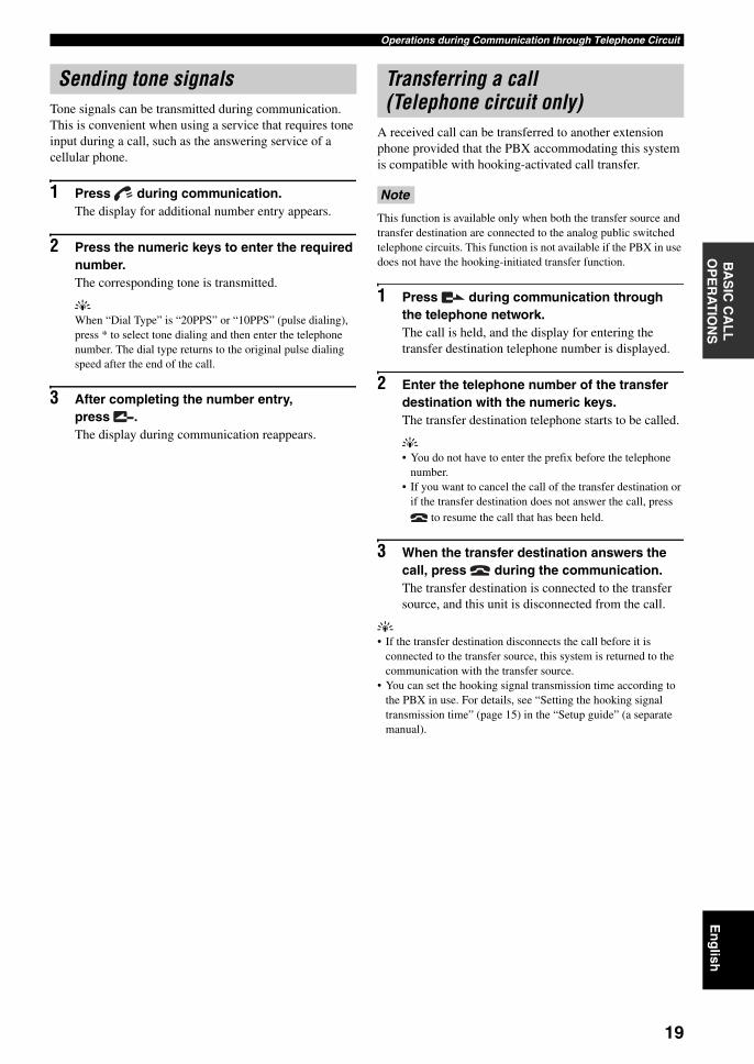
Tone signals can be transmitted during communication. This is convenient when using a service that requires tone input during a call, such as the answering service of a cellular phone.
1 Press during communication.The display for additional number entry appears.
2 Press the numeric keys to enter the required number.The corresponding tone is transmitted.
yWhen “Dial Type” is “20PPS” or “10PPS” (pulse dialing), press * to select tone dialing and then enter the telephone number. The dial type returns to the original pulse dialing speed after the end of the call.
3 After completing the number entry, press .The display during communication reappears.
A received call can be transferred to another extension phone provided that the PBX accommodating this system is compatible with hooking-activated call transfer.
This function is available only when both the transfer source and transfer destination are connected to the analog public switched telephone circuits. This function is not available if the PBX in use does not have the hooking-initiated transfer function.
1 Press during communication through the telephone network.The call is held, and the display for entering the transfer destination telephone number is displayed.
2 Enter the telephone number of the transfer destination with the numeric keys.The transfer destination telephone starts to be called.
y• You do not have to enter the prefix before the telephone
number.• If you want to cancel the call of the transfer destination or
if the transfer destination does not answer the call, press to resume the call that has been held.
3 When the transfer destination answers the call, press during the communication.The transfer destination is connected to the transfer source, and this unit is disconnected from the call.
y• If the transfer destination disconnects the call before it is
connected to the transfer source, this system is returned to the communication with the transfer source.
• You can set the hooking signal transmission time according to the PBX in use. For details, see “Setting the hooking signal transmission time” (page 15) in the “Setup guide” (a separate manual).
Sending tone signals Transferring a call (Telephone circuit only)
Note
19

TROUBLESHOOTING
Refer to the following tables when this unit does not function properly. If the problem you are experiencing is not listed or if the instruction does not help, contact your nearest authorized YAMAHA dealer or service center.
First, check if the microphone indicators light up. If the indicator is turned off, see “Q1: LED indicators do not light up” below. For other cases, refer to one of the following pages according to the problem.
– “Q2: A call cannot be made” (page 21)– “Q3: Other problems” (page 22)
Troubleshooting
Q1: LED indicators do not light up
Problem Cause Remedy
The microphone indicators do not light up.
This unit is not turned on. Check that the AC adapter and power cable are connected properly.
The power cable is not connected to the AC outlet.
Check that the power cable is connected to the AC outlet properly.
The main or branch circuit breaker is shut off.
If the circuit breaker is tripped to “OFF”, set it to “ON”.
If the circuit breaker is “ON”, set it to “OFF” then “ON” again.
There is a power failure. Wait until the power supply is restored.
Power is not supplied to the AC outlet. If another electrical appliance also cannot be turned on, have the power outlet or power wiring serviced.
If another electrical appliance can be turned on, have this unit serviced.
The microphones are muted (the MIC MUTE LED lights up).
Press MIC MUTE so that the MIC MUTE LED is turned off.
20

TroubleshootingE
ng
lishA
DD
ITIO
NA
L
INF
OR
MA
TIO
N
Q2: A call cannot be made
Problem Cause Remedy
A call cannot be originated. An inappropriate IP address is entered. Check the IP address of the other unit and enter the correct IP address.
The IP address of the other unit has been changed.
Check the IP address of the other unit and enter the correct IP address.
The communication is blocked by a firewall. Call by designating the IP address cannot cross a firewall. If you want to change the calling method to SIP, consult your system administrator.
A network fault occurred. Wait until the fault is released.
Consult your system administrator.
The connection mode settings of this unit and the other unit are different.
A unit in the mesh connection mode cannot communicate with a unit in a cascade connection mode. Set the two units to the same connection mode (page 14 in the “Setup guide” (a separate manual)).
The IP/SIP settings of this unit and the other unit are different.
A unit using the SIP address cannot communicate with a unit using the IP address. Enable or disable the SIP server operation as required so that both units use the same type of address (page 24 in the “Setup guide” (a separate manual)).
The SIP address in the address book is incorrect.
Register the correct SIP address (page 23 in the “Setup guide” (a separate manual)).
The SIP server is not running. Consult your system administrator.
The SIP address of the other unit is not registered in the SIP server.
Consult your system administrator.
The Dial Type setup of this system differs from the actual type of the telephone line.
Check the telephone line type and set the Dial Type setup of this system accordingly.
This unit is connected to an incompatible telephone circuit (digital circuit, etc.).
Consult the manager of your telephone circuit.
A call cannot be received. An incorrect IP address is entered on the other unit.
Enter the correct IP address on the other unit.
The communication is blocked by a firewall. Call by designating the IP address cannot cross a firewall. If you want to change the calling method to SIP, consult your system administrator.
A network fault occurred. Wait until the fault is released.
Consult your system administrator.
21
Troubleshooting
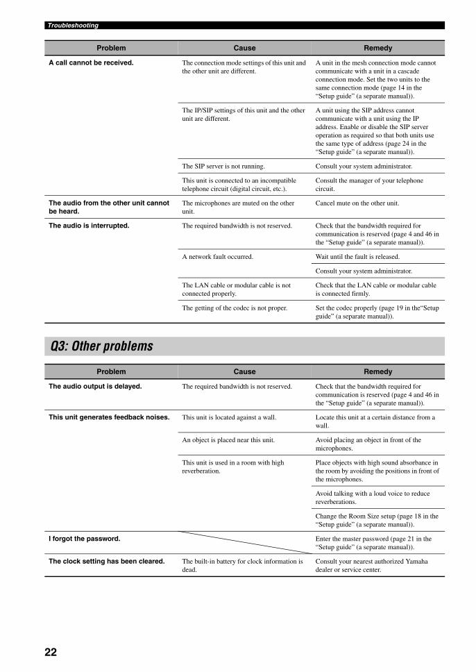
Problem Cause Remedy
A call cannot be received. The connection mode settings of this unit and the other unit are different.
A unit in the mesh connection mode cannot communicate with a unit in a cascade connection mode. Set the two units to the same connection mode (page 14 in the “Setup guide” (a separate manual)).
The IP/SIP settings of this unit and the other unit are different.
A unit using the SIP address cannot communicate with a unit using the IP address. Enable or disable the SIP server operation as required so that both units use the same type of address (page 24 in the “Setup guide” (a separate manual)).
The SIP server is not running. Consult your system administrator.
This unit is connected to an incompatible telephone circuit (digital circuit, etc.).
Consult the manager of your telephone circuit.
The audio from the other unit cannot be heard.
The microphones are muted on the other unit.
Cancel mute on the other unit.
The audio is interrupted. The required bandwidth is not reserved. Check that the bandwidth required for communication is reserved (page 4 and 46 in the “Setup guide” (a separate manual)).
A network fault occurred. Wait until the fault is released.
Consult your system administrator.
The LAN cable or modular cable is not connected properly.
Check that the LAN cable or modular cable is connected firmly.
The getting of the codec is not proper. Set the codec properly (page 19 in the“Setup guide” (a separate manual)).
Q3: Other problems
Problem Cause Remedy
The audio output is delayed. The required bandwidth is not reserved. Check that the bandwidth required for communication is reserved (page 4 and 46 in the “Setup guide” (a separate manual)).
This unit generates feedback noises. This unit is located against a wall. Locate this unit at a certain distance from a wall.
An object is placed near this unit. Avoid placing an object in front of the microphones.
This unit is used in a room with high reverberation.
Place objects with high sound absorbance in the room by avoiding the positions in front of the microphones.
Avoid talking with a loud voice to reduce reverberations.
Change the Room Size setup (page 18 in the “Setup guide” (a separate manual)).
I forgot the password. Enter the master password (page 21 in the “Setup guide” (a separate manual)).
The clock setting has been cleared. The built-in battery for clock information is dead.
Consult your nearest authorized Yamaha dealer or service center.
22

YAMAHA CORPORATION 10-1 Nakazawa-cho, Hamamatsu, Shizuoka 430-8650, Japan
© 2006 All rights reserved.
Printed in Japan WJ13580-2
This owner’s manual is based on the latest version of the firmware as of October, 2007. The functions and specifications could be possibly added or changed by a firmware update.Visit the PJP website to obtain the latest firmware and manuals.
PJP website:http://www.yamaha.co.jp/english/product/projectphone/
Ce mode d’emploi se réfère à la toute dernière version dumicrologiciel, celle d’octobre 2007. Des fonctions et spécificationspeuvent être ajoutées ou changées par une mise à jour dumicrologiciel.Consultez le site PJP pour obtenir les tout derniers micrologiciel etmanuels.
Site PJP:http://www.yamaha.co.jp/english/product/projectphone/
Dieses Benutzerhandbuch basiert auf der neuesten Version derFirmware vom Stand Oktober 2007. Die Funktionen und technischenDaten können möglicherweise durch eine zukünftige Firmware-Aktualisierung erweitert oder geändert werden.Besuchen Sie die PJP-Website zum Erhalten der neuesten Firmwareund Anleitungen.
PJP-Website:http://www.yamaha.co.jp/english/product/projectphone/
As of October, 2007
01EN1_PJP-50R_UCGB_cv4-1.fm Page 1 Monday, October 1, 2007 11:55 AM