pitts 50cc manual - generalhobby.comgeneralhobby.com/manuals/pitts-50cc.pdf · 2.position the...
TRANSCRIPT

50cc Assembly Manual
1
50cc Assembly Manual
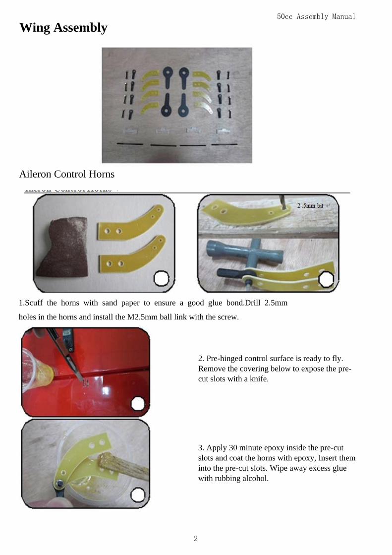
Wing Assembly
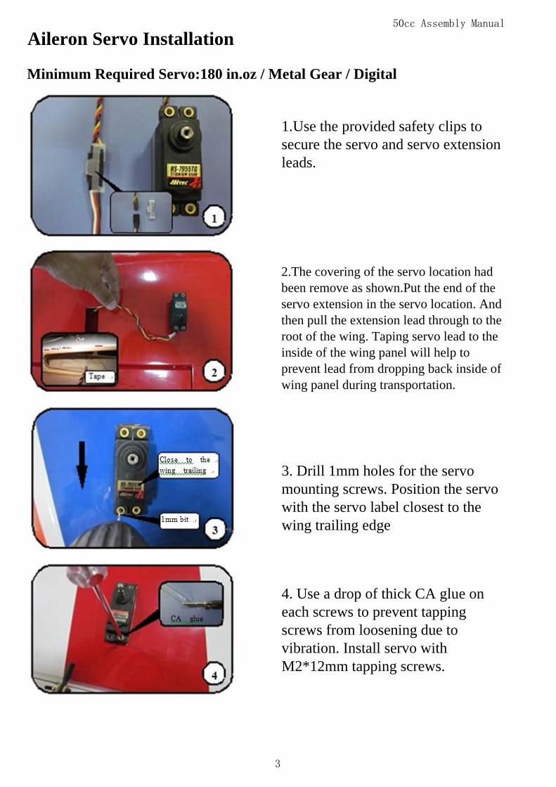
Aileron Control Horns
1.Scuff the horns with sand paper to ensure a good glue bond.Drill 2.5mm
holes in the horns and install the M2.5mm ball link with the screw.
2. Pre-hinged control surface is ready to fly.Remove the covering below to expose the pre-cut slots with a knife.
3. Apply 30 minute epoxy inside the pre-cutslots and coat the horns with epoxy, Insert theminto the pre-cut slots. Wipe away excess gluewith rubbing alcohol.
2
50cc Assembly Manual
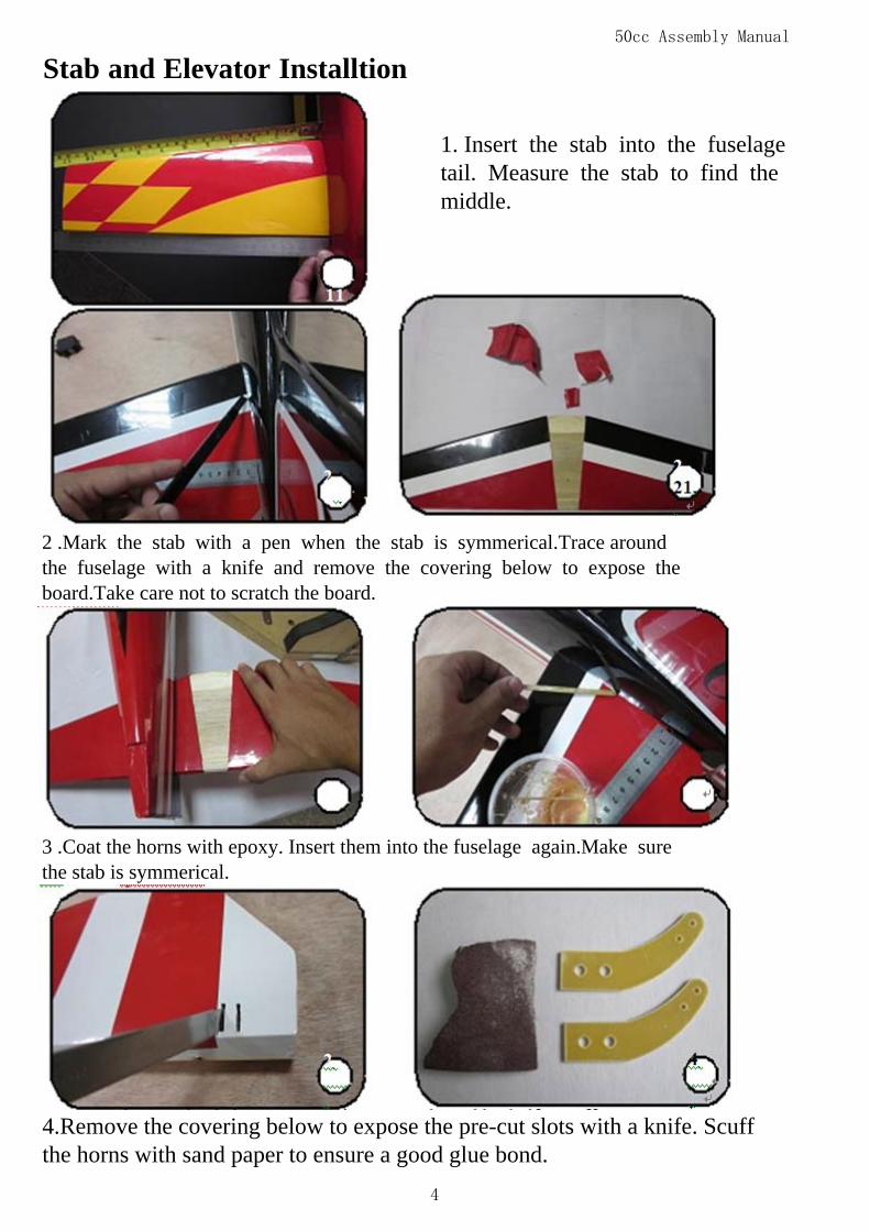
Aileron Servo Installation
Minimum Required Servo:180 in.oz / Metal Gear / Digital
1.Use the provided safety clips tosecure the servo and servo extensionleads.
2.The covering of the servo location hadbeen remove as shown.Put the end of theservo extension in the servo location. Andthen pull the extension lead through to theroot of the wing. Taping servo lead to theinside of the wing panel will help toprevent lead from dropping back inside ofwing panel during transportation.
3. Drill 1mm holes for the servomounting screws. Position the servowith the servo label closest to thewing trailing edge
4. Use a drop of thick CA glue oneach screws to prevent tappingscrews from loosening due tovibration. Install servo withM2*12mm tapping screws.
3
50cc Assembly Manual
Stab and Elevator Installtion
1. Insert the stab into the fuselagetail. Measure the stab to find themiddle.
3 .Coat the horns with epoxy. Insert them into the fuselage again.Make surethe stab is symmerical.
4.Remove the covering below to expose the pre-cut slots with a knife. Scuffthe horns with sand paper to ensure a good glue bond.
2 .Mark the stab with a pen when the stab is symmerical.Trace aroundthe fuselage with a knife and remove the covering below to expose theboard.Take care not to scratch the board.
4
50cc Assembly Manual
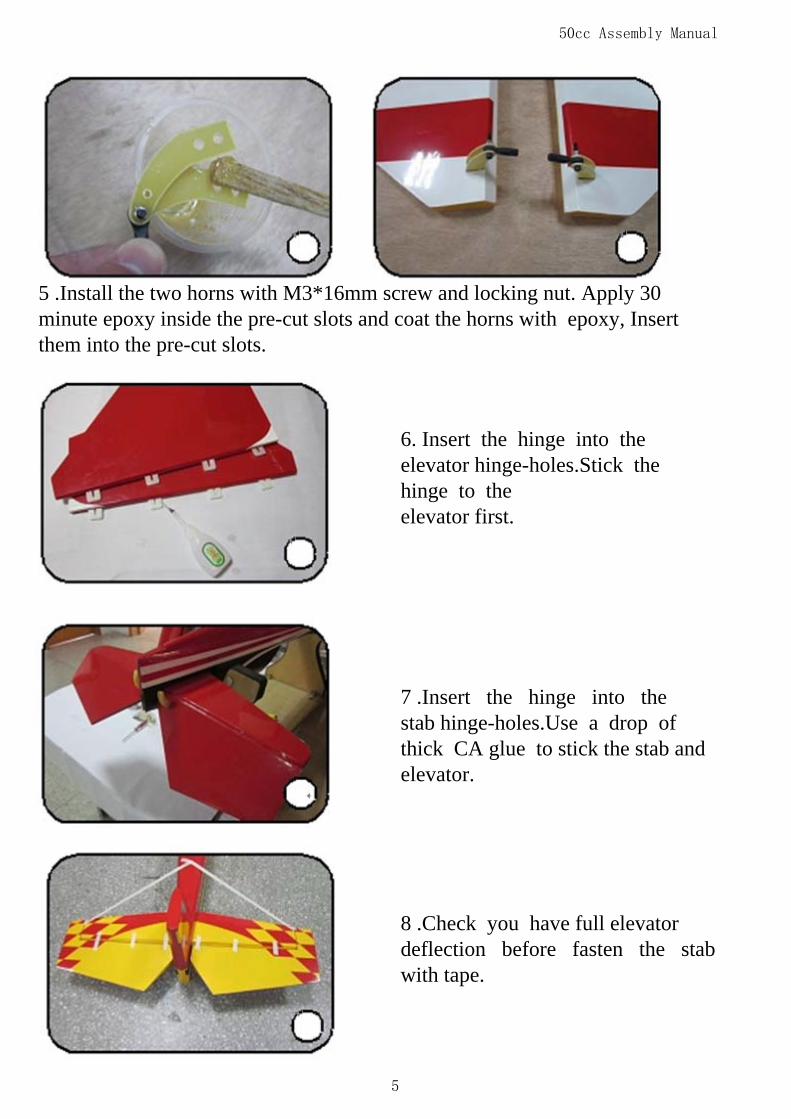
6. Insert the hinge into theelevator hinge-holes.Stick thehinge to theelevator first.
8 .Check you have full elevatordeflection before fasten the stabwith tape.
7 .Insert the hinge into thestab hinge-holes.Use a drop ofthick CA glue to stick the stab andelevator.
5 .Install the two horns with M3*16mm screw and locking nut. Apply 30minute epoxy inside the pre-cut slots and coat the horns with epoxy, Insertthem into the pre-cut slots.
5
50cc Assembly Manual
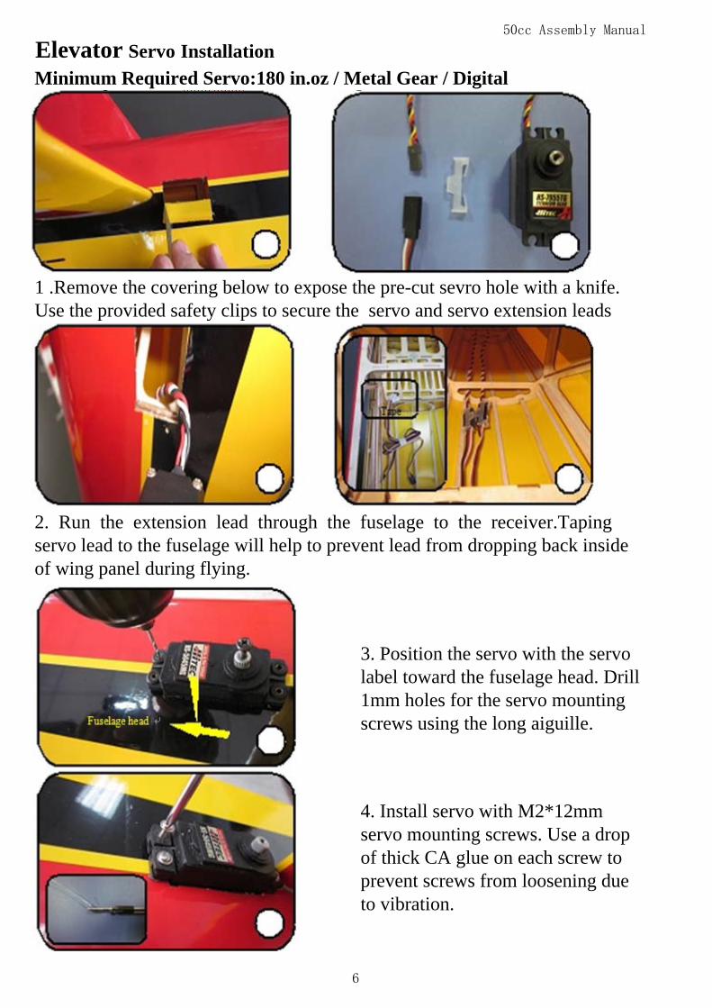
Elevator Servo InstallationMinimum Required Servo:180 in.oz / Metal Gear / Digital
2. Run the extension lead through the fuselage to the receiver.Tapingservo lead to the fuselage will help to prevent lead from dropping back insideof wing panel during flying.
3. Position the servo with the servolabel toward the fuselage head. Drill1mm holes for the servo mountingscrews using the long aiguille.
4. Install servo with M2*12mmservo mounting screws. Use a dropof thick CA glue on each screw toprevent screws from loosening dueto vibration.
1 .Remove the covering below to expose the pre-cut sevro hole with a knife.Use the provided safety clips to secure the servo and servo extension leads
6

50cc Assembly Manual
7. Repeat all the previous steps for the other elevator.
Rudder Assembly
5. Turn on the transmitter. Makesure the servo is in the neutralposition. Install the servo arm.Position the servo arm 90 degrees tothe servo,and tighten the arm screw.
6. Adjust the pushrod length so that the servo and elevator are both inthe neutral position.Install the arm pushrod with M3*16mm screw and locknut.
7

50cc Assembly Manual
Rudder Horns and Hinges
1 .Trace around the fuselage with a knife and remove the covering below toexpose the board. Take care not to scratch the board.
2. Remove the covering below toexpose the pre-cut slots with a knife.
3. Scuff the middle of horns withsand paper to ensure a good gluebond. Apply 30 minute epoxy insidethe pre-cut slots. Coat the horns withepoxy.Insert them into the pre-cutslots.
4. Install the ball link withM2.5*16mm screws and locking
nuts. Tightening the nuts isrecommended. Wipe away excessglue with rubbing alcohol. Make
sure the horns are correctly alignedand symmetry before the apoxy has
cured.
8

50cc Assembly Manual
Rudder Servo Installation
Minimum Required Servo:180 in.oz / Metal Gear / Digital
2. Position the servo with the servolabel toward the fuselage tail. Fastenthe servo wire with the tape.
5. Insert the hinge into the rudderhinge-holes. Stick the hinge to therudder first.
6. Insert the hinge into thehinge-holes. Use a drop of thick CA glueto stick the stab and elevator.
1. The rudder cables and couplershave been pre-installed.
9
50cc Assembly Manual
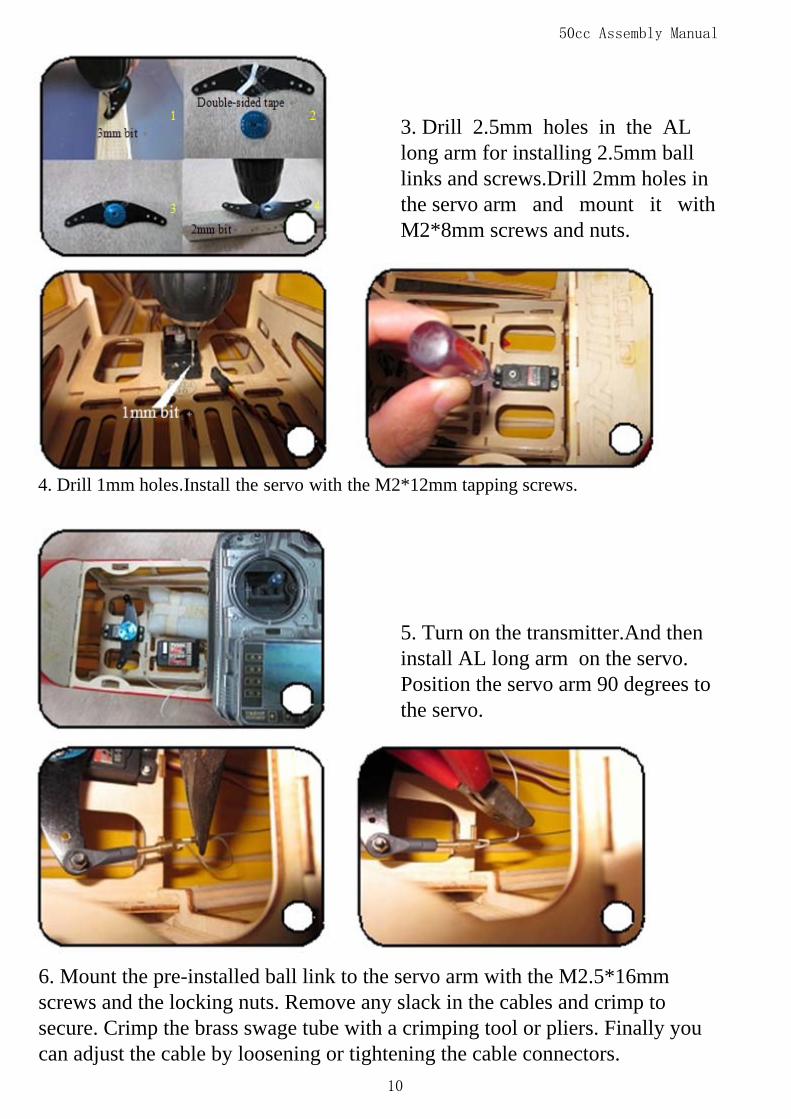
3. Drill 2.5mm holes in the ALlong arm for installing 2.5mm balllinks and screws.Drill 2mm holes inthe servo arm and mount it withM2*8mm screws and nuts.
4. Drill 1mm holes.Install the servo with the M2*12mm tapping screws.
5. Turn on the transmitter.And theninstall AL long arm on the servo.Position the servo arm 90 degrees tothe servo.
6. Mount the pre-installed ball link to the servo arm with the M2.5*16mmscrews and the locking nuts. Remove any slack in the cables and crimp tosecure. Crimp the brass swage tube with a crimping tool or pliers. Finally youcan adjust the cable by loosening or tightening the cable connectors.
10
50cc Assembly Manual
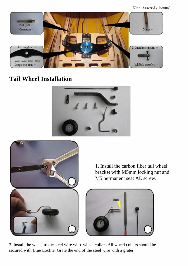
Tail Wheel Installation
1. Install the carbon fiber tail wheelbracket with M5mm locking nut andM5 permanent seat AL screw.
2. Install the wheel to the steel wire with wheel collars.All wheel collars should besecured with Blue Loctite. Grate the end of the steel wire with a grater.
11
50cc Assembly Manual
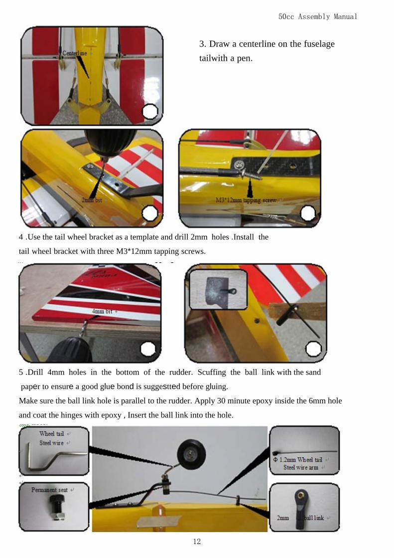
3. Draw a centerline on the fuselagetailwith a pen.
4 .Use the tail wheel bracket as a template and drill 2mm holes .Install the
tail wheel bracket with three M3*12mm tapping screws.
5 .Drill 4mm holes in the bottom of the rudder. Scuffing the ball link with the sand
paper to ensure a good glue bond is suggestted before gluing.
Make sure the ball link hole is parallel to the rudder. Apply 30 minute epoxy inside the 6mm hole
and coat the hinges with epoxy , Insert the ball link into the hole.
12
50cc Assembly Manual
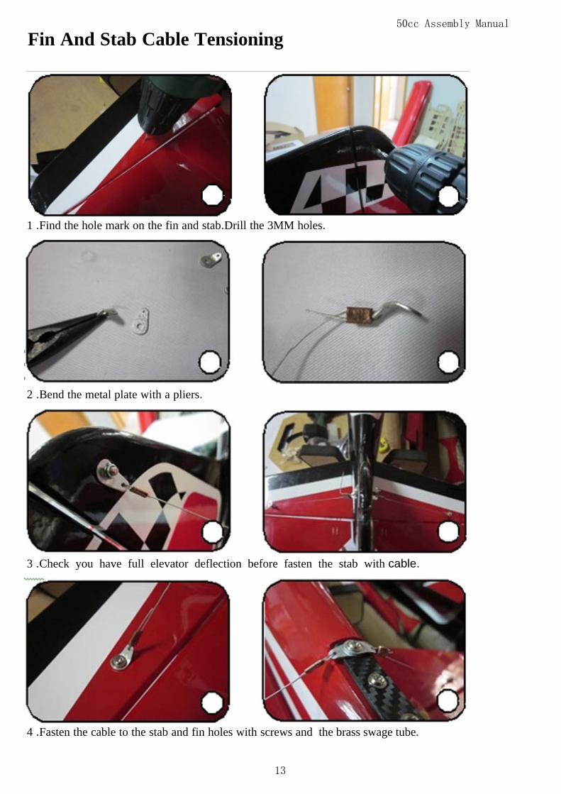
Fin And Stab Cable Tensioning
1 .Find the hole mark on the fin and stab.Drill the 3MM holes.
2 .Bend the metal plate with a pliers.
3 .Check you have full elevator deflection before fasten the stab with cable.
4 .Fasten the cable to the stab and fin holes with screws and the brass swage tube.
13
50cc Assembly Manual
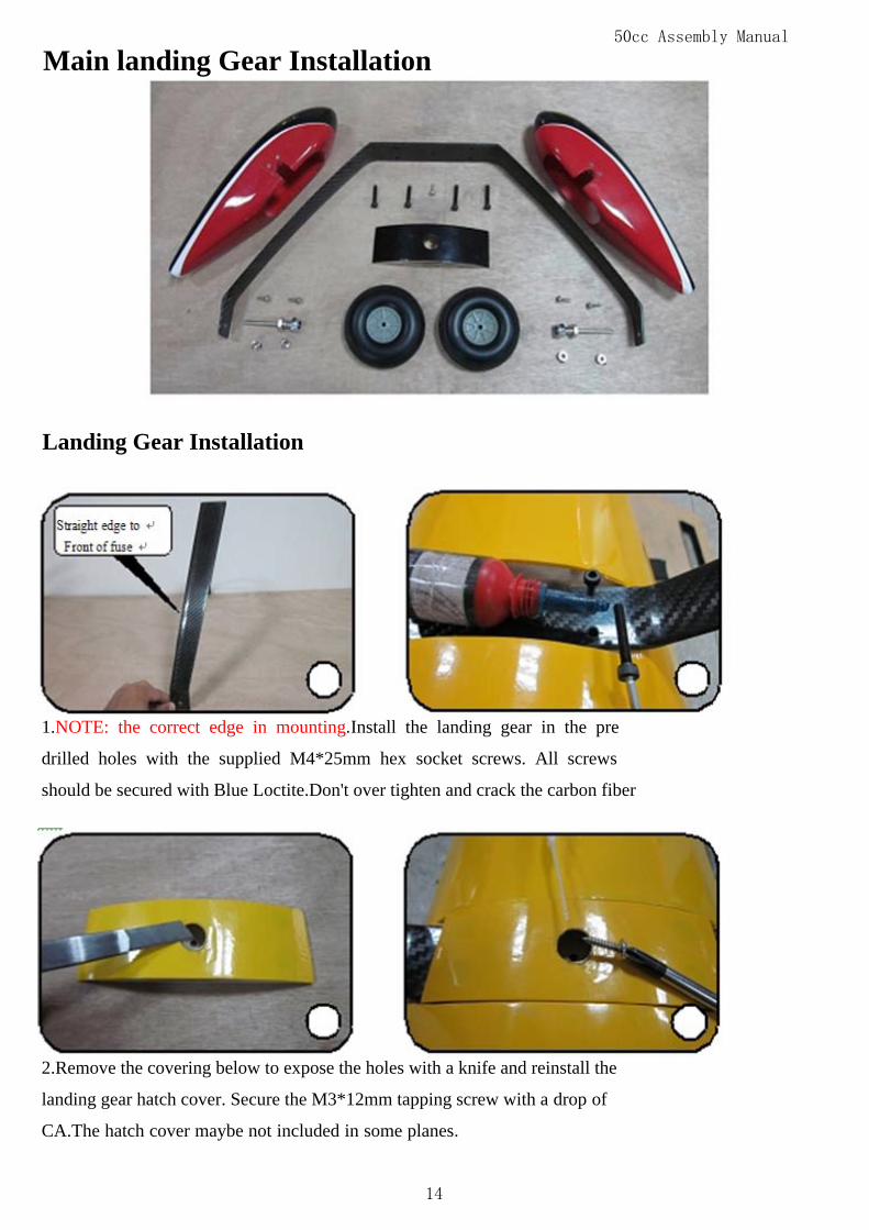
Main landing Gear Installation
Landing Gear Installation
1.NOTE: the correct edge in mounting.Install the landing gear in the pre
drilled holes with the supplied M4*25mm hex socket screws. All screws
should be secured with Blue Loctite.Don't over tighten and crack the carbon fiber
2.Remove the covering below to expose the holes with a knife and reinstall the
landing gear hatch cover. Secure the M3*12mm tapping screw with a drop of
CA.The hatch cover maybe not included in some planes.
14

50cc Assembly Manual
3.Tighten the M8 locking nut against
the landing gear strut.(for some planes)
Pants Installation
1.Install the inner wheel collar on the axle. screw and tighten the wheel collar
in place. Adjust wheel collars in or out until wheel turns freely.
2 .And then install the wheel pant
with two M2.5*12mm screws.
15
50cc Assembly Manual
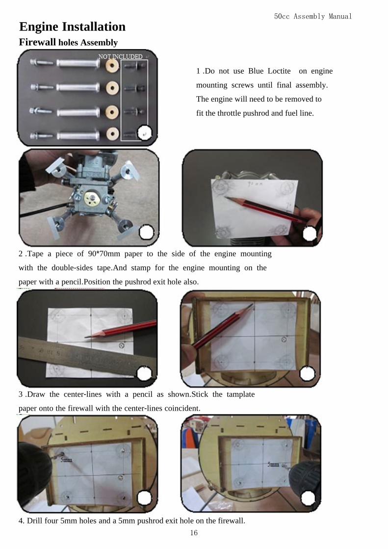
Engine InstallationFirewall holes Assembly
1 .Do not use Blue Loctite on engine
mounting screws until final assembly.
The engine will need to be removed to
fit the throttle pushrod and fuel line.
2 .Tape a piece of 90*70mm paper to the side of the engine mounting
with the double-sides tape.And stamp for the engine mounting on the
paper with a pencil.Position the pushrod exit hole also.
3 .Draw the center-lines with a pencil as shown.Stick the tamplate
paper onto the firewall with the center-lines coincident.
4. Drill four 5mm holes and a 5mm pushrod exit hole on the firewall. 16
50cc Assembly Manual
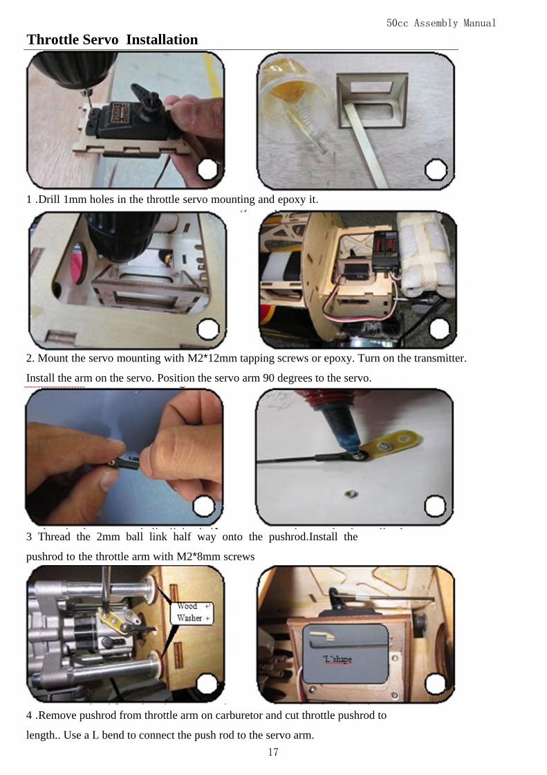
Throttle Servo Installation
1 .Drill 1mm holes in the throttle servo mounting and epoxy it.
2. Mount the servo mounting with M2*12mm tapping screws or epoxy. Turn on the transmitter.
Install the arm on the servo. Position the servo arm 90 degrees to the servo.
3 Thread the 2mm ball link half way onto the pushrod.Install the
pushrod to the throttle arm with M2*8mm screws
4 .Remove pushrod from throttle arm on carburetor and cut throttle pushrod to
length.. Use a L bend to connect the push rod to the servo arm. 17
50cc Assembly Manual
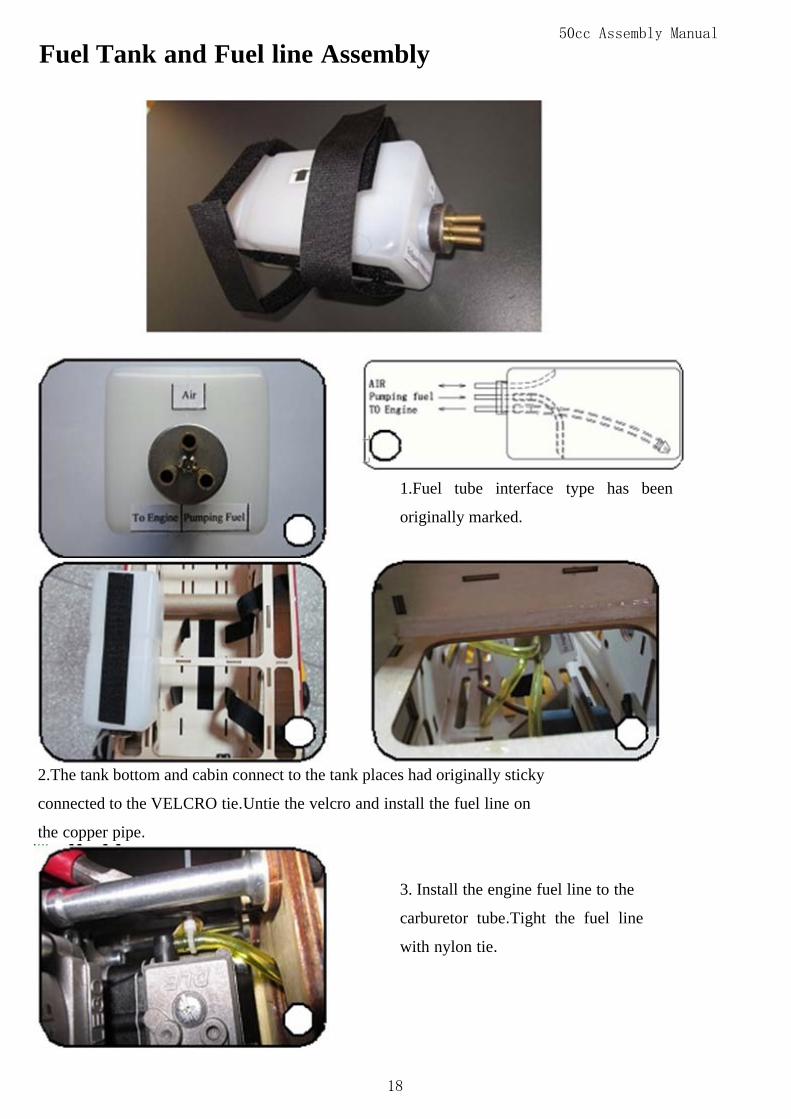
Fuel Tank and Fuel line Assembly
1.Fuel tube interface type has been
originally marked.
2.The tank bottom and cabin connect to the tank places had originally sticky
connected to the VELCRO tie.Untie the velcro and install the fuel line on
the copper pipe.
3. Install the engine fuel line to the
carburetor tube.Tight the fuel line
with nylon tie.
18

50cc Assembly Manual
4 .Drill a 6mm hole on the side of the fuselage.Then let 6mm pumping fuel line pass
through the hole.Install the M5mm screw to seal the fuel line
5.Drill a 6mm hole on the bottom of the fuselage.Let air line pass
through the hole. Tighting the line with nylon tie will help to prevent
lead from drawwing back inside of fuselage during flying.Retight the
tank with the velcro tie after the fuel lines are all right.
Ignition and the battery Assembly
1. Trim a piece of foam rubber to the ignition module. Make the pad slightly
larger than the ignition module. Bundle the ignition with tape as shown.
19
50cc Assembly Manual
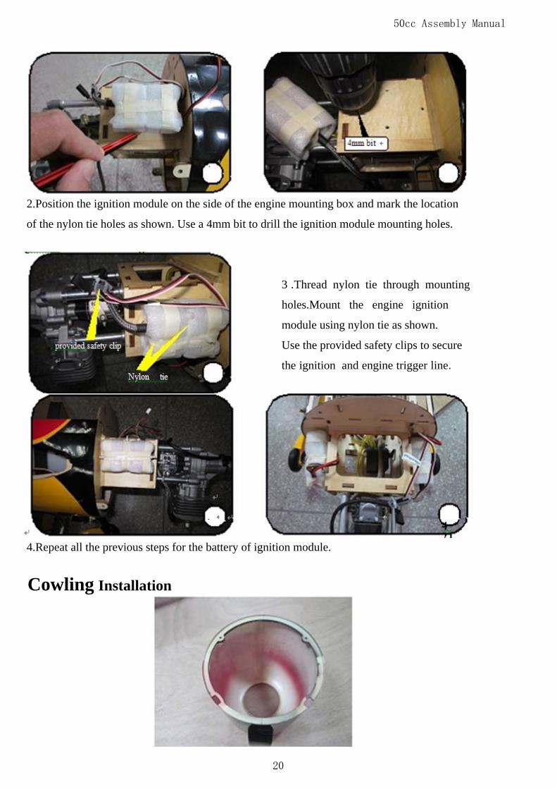
2.Position the ignition module on the side of the engine mounting box and mark the location
of the nylon tie holes as shown. Use a 4mm bit to drill the ignition module mounting holes.
3 .Thread nylon tie through mounting
holes.Mount the engine ignition
module using nylon tie as shown.
Use the provided safety clips to secure
the ignition and engine trigger line.
4.Repeat all the previous steps for the battery of ignition module.
Cowling Installation
20
50cc Assembly Manual
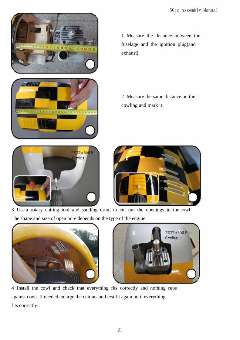
1 .Measure the distance between the
fuselage and the ignition plug(and
exhaust).
2 .Measure the same distance on the
cowling and mark it.
3 .Use a rotary cutting tool and sanding drum to cut out the openings in the cowl.
The shape and size of open pore depends on the type of the engine.
4 .Install the cowl and check that everything fits correctly and nothing rubs
against cowl. If needed enlarge the cutouts and test fit again until everything
fits correctly.
21

50cc Assembly Manual
5 .Measure the distance of the blind
nut on the cowling and mark it.
6 .Drill two 4mm holes in place.And install the cowling with four
M3*16mm screws with washers.
Wing Final Assembly
2.Install the nylon bolts to the wing
blind nuts. Tighten snugly but do not
over tighten. Slide the wings on the
wing tube and plug in the aileron servo
connectors.
22

50cc Assembly Manual
3.Install the AL wing bracing to the fuselage with M3*16 screws.
4.Install the upper wing with the wing bracing and locking nuts.
Canopy Assembly
1.Install the canopy to the front of fuselage.Tighten the canopy with
theM3*16mm nylon bolts.
23
50cc Assembly Manual
Flight Preparation
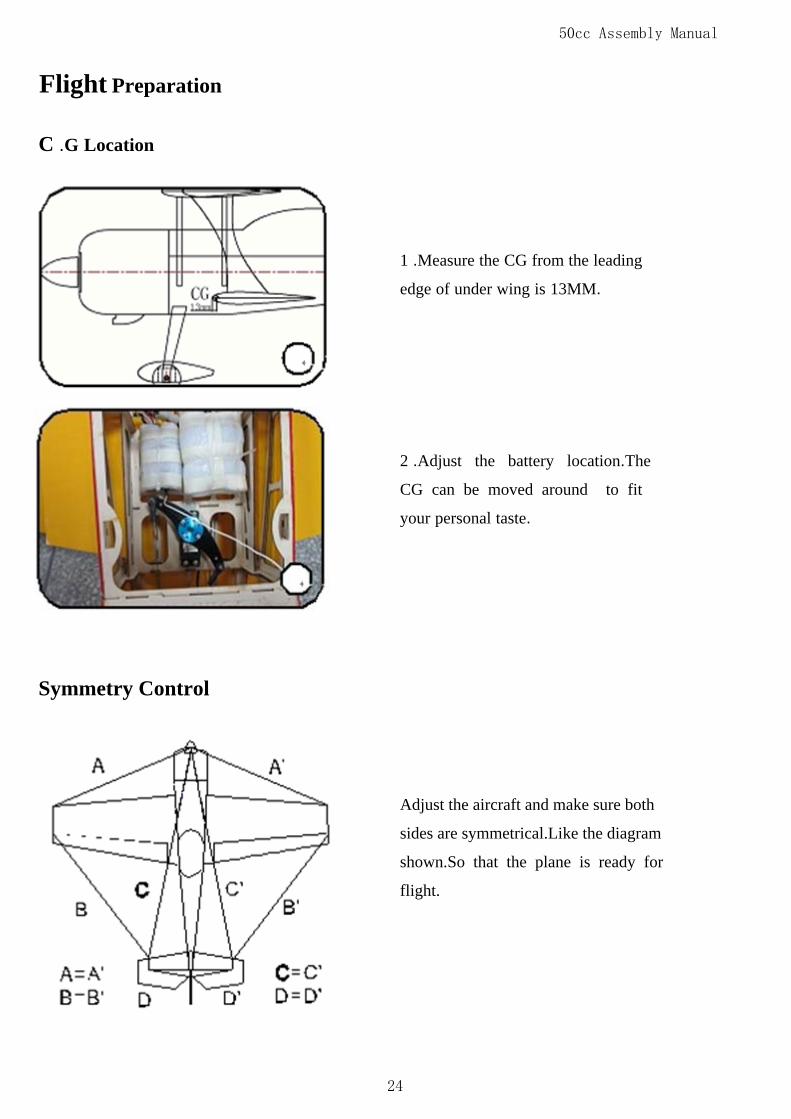
C .G Location
1 .Measure the CG from the leading
edge of under wing is 13MM.
2 .Adjust the battery location.The
CG can be moved around to fit
your personal taste.
Symmetry Control
Adjust the aircraft and make sure both
sides are symmetrical.Like the diagram
shown.So that the plane is ready for
flight.
24
50cc Assembly Manual
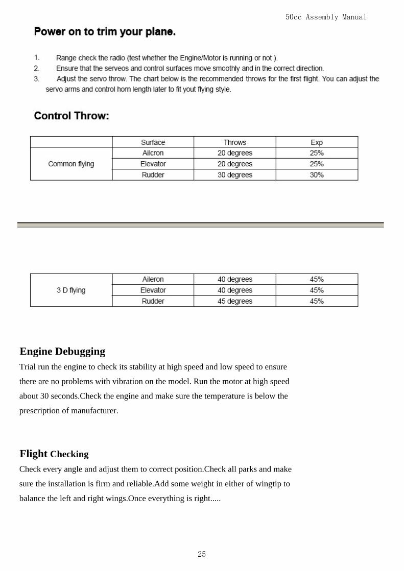
Engine Debugging Trial run the engine to check its stability at high speed and low speed to ensure
there are no problems with vibration on the model. Run the motor at high speed
about 30 seconds.Check the engine and make sure the temperature is below the
prescription of manufacturer.
Flight CheckingCheck every angle and adjust them to correct position.Check all parks and make
sure the installation is firm and reliable.Add some weight in either of wingtip to
balance the left and right wings.Once everything is right.....
25