piston engine construction
TRANSCRIPT

Reciprocating engine components
• The crankcase is that part of the engine block below the cylinders. It supports and
encloses the crankshaft and provides a reservoir for the lubricating oil.
• The crankcase holds all of the engine parts in alignment and supports the cylinders and
crankshaft
• It provides a place to mount the engine to the aircraft
• Constructed of aluminum alloy
• Divided into sections (radial)
Crankcase

• Nose section - Houses prop shaft and bearings
• Power section - mount for cylinders
• Fuel induction section - intake tubes, blower, manifolds (supercharger)
• Accessory section - mounts for magnetos, pumps, generators (magnesium)
Crankcase

• Opposed crankcase
• Sections are not as distinct as in the radial and the crankcase splits from front to rear instead of in radial sections
Crankcase

Crankshaft

• Constructed of chrome-nickel-molybdenum-steel
• May be one piece or as many as three separate pieces
• The crankshaft rotates within the crankcase and is supported by main bearing journals
• Crankshaft throws or crankpins are off center and account for the reciprocating motion of the pistons
Crankshaft

Crankshaft

• Counterweights are used to reduce vibration but they are rigid
• Counterweights are used in piston engines because the power pulses and movement of the pistons create large amounts of vibration
• Vibration shortens airframe and engine life and can lead to premature component failure
Crankshaft

• 2 Piece Crankshaft With Counterweights (Single Throw, Single Cylinder)
Crankshaft

Camshaft

• Used to open the valves for intake and exhaust
• Must be mechanically coupled to the crankshaft for timing purposes (gears, belts, chains)
• The camshaft consists of bearing journals and lobes spaced along the shaft
• Each lobe is positioned to open and close a valve at a specific time
Lobe
Camshaft

Sump

• reservoir for the lubricating oil.
• A wet sump is a lubricating oil management design for piston engines which uses
the crankcase as a built-in reservoir for oil.
• Piston engines are lubricated by oil which is pumped into various bearings, and
thereafter allowed to drain to the base of the engine under gravity.
• A wet sump offers the advantage of a simple design, using a single pump and no
external reservoir.
Sump

Accessory gearbox

• The accessory drive gearbox is most often attached directly to the outside cases of the
engine at or near the bottom.
• The accessory gearbox is driven the crankshaft of the engine.
• The gearbox has attachment pads on it for accessories that need to be mechanically driven.
Accessory gearbox

Cylinder barrel

Cylinder Barrel
• Chrome-molybdenum or nickel-molybdenum steel• Used to guide and seal piston and to mount cylinder assembly to head• Barrel threads into head to form cylinder assembly

Cylinder head
• Valve• Spark plug
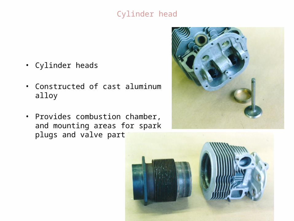
• Cylinder heads
• Constructed of cast aluminum alloy
• Provides combustion chamber, and mounting areas for spark plugs and valve parts
Cylinder head

• The cylinder head is designed to transfer heat by conduction to the fins and then from the fins to the air by convection
Cylinder head

Piston

• Constructed of aluminum alloy
• Parts include top, ring grooves, ring lands, skirt, and piston pin boss
• Cooling fins on the bottom help the oil carry heat away from the piston top
Piston

Ring

• Provide seal between cylinder wall and piston• Rings ride on a thin film of oil• Conduct heat from the piston out to the cylinder and the fins• Material is cast iron or chrome steel
• Piston rings (type)• compression ring is to prevent gases from leaking by the piston during the
compression and power strokes.
• The oil ring, usually located just above the piston pin,it is an oil-regulating ring. This ring scrapes the excess oil from the cylinder walls and returns some of it, through slots, to the piston ring grooves.
Ring

• The gap at the end of the rings allows for expansion and contraction and unevenness in the cylinder wall .
• Always place the end gaps during ring installation away from each other to prevent losing compression.
Ring

Piston Pin
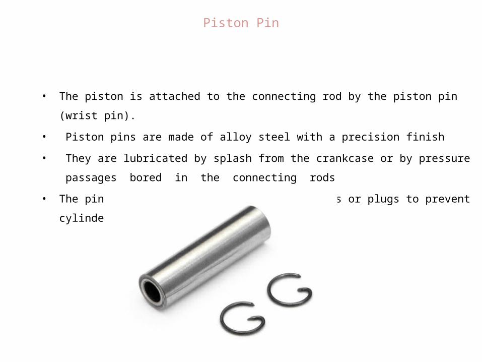
• The piston is attached to the connecting rod by the piston pin (wrist pin).
• Piston pins are made of alloy steel with a precision finish
• They are lubricated by splash from the crankcase or by pressure passages bored in the
connecting rods
• The pin is retained in the piston with clips or plugs to prevent cylinder wall scoring
Piston Pin
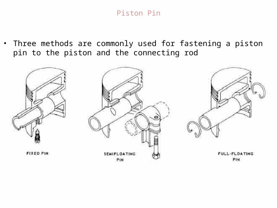
• Three methods are commonly used for fastening a piston pin to the piston and the connecting rod
Piston Pin

Connecting rod

• Connecting Rod Assembly
• The link between the crankshaft and the piston
• Normally steel but some low powered engines use aluminum to save weight
• Types include : Plain Rod
Fork and blade rod
Master and articulated
Connecting Rod