pipe shields catalogue - imatechimatech.com.au/.../uploads/energypdfs/pipe-shields-catalogue.pdf ·...
TRANSCRIPT

1
GENERAL INTRODUCTION
ipe Shields Inc. pioneered the first insulated pipe support, in 1971, for use on HVAC and plumbing lines. These supports were designed because fiberglass pipe insulation is not strong enough to carry
the load at the point of support without crushing. The various methods contractors employed to compensate for this weakness were inconsistent, non-uniform and labor intensive, often resulting in damage to the vapor barrier and/or pipe insulation. The insulated pipe support filled the need for an energy efficient, economical and practical support. Pipe Shields Inc. has developed a large and growing family of insulated pipe supports, using its “standard concept” of incorporating materials strong enough to carry the load while insulating the pipe at the same time. No welding to the pipe is required (except for insulated positive anchors and insulated pipe riser clamps) and no direct metal-to-metal heat path exists. Insulated pipe supports meet an assortment of requirements, including:
· Pipe supported on: o Flat Surface o Pipe Roll o Clevis Hanger
· Gas · Steam · Super Heated Steam · Chilled Water · Styrene · Guide Supports · Sliding Supports · Restrained Supports
· Anchors · Pipe Hangers · Pipe Riser Clamps · Thermal Growth – Small or Large · Maximum Support Spacing · Light, Medium or Heavy Loads · Ultra-High Temperatures · Minimum Overhead Clearance · Minimum Horizontal Clearance · Minimum Field Labor · Minimum Friction Loads · Easy Installation
Other products designed, manufactured and supplied not included in this catalog are:
1. Cryogenic supports 2. Seismic pipe restraints 3. Heat-traced pre-insulated pipe supports 4. Pipe supports used in computer chip, styrene plants and oil refineries 5. Pipe supports for solar energy projects to accommodate expansion travels in excess of 5’- 0”
Our highly sophisticated products are a direct result of years of research, engineering and design to develop cost efficient products for the power, petrochemical, chemical and commercial markets. We work closely with engineering firms and in-house engineering departments of owners to provide working solutions to meet their engineering challenges. We have established proprietary specifications that have now become an industry standard used by owners, engineers and contractors throughout the world markets. If you have a pipe support need not met by any of the items described in this catalog, please contact us at
713-731-0030 or 1-800-787-5914.
P
FRONEK GROUP
CATALOG PS-2004
2
TEMPERATURE, DIMENSIONAL AND MATERIAL VARIANCES
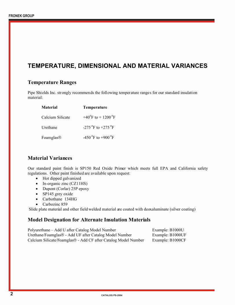
Temperature Ranges Pipe Shi elds Inc. str ongly recommen ds the foll owing temper ature range s for our stan dard insulati on material: Material Temperature Calcium Silicate +40oF to + 1200 oF Urethane -275 oF to +275 oF Foamglasâ -450 oF to +900 oF
Material Variances Our standard paint finish is SP150 Red Oxide Primer which meets full EPA and California safety regulations. Other paint finished are available upon request:
· Hot dipped galvanized · In-organic zinc (CZ11HS) · Dupont (Corlar) 25P epoxy · SP145 grey oxide · Carbothane 134HG · Carbozinc 859
Slide plate material and other field welded material are coated with deoxaluminate (silver coating)
Model Designation for Alternate Insulation Materials Polyurethane – Add U after Catalog Model Number Example: B1000U Urethane/Foamglasâ - Add UF after Catalog Model Number Example: B1000UF Calcium Silicate/Foamglasâ - Add CF after Catalog Model Number Example: B1000CF
FRONEK GROUP
CATALOG PS-2004

3
INSULATED PIPE SUPPORT SELECTION GUIDEFRONEK GROUP
CATALOG PS-2004
1.
A. Water
B. Steam, Gas, or Air
2. APPLICATION
A. Pipe supported from below
a. On flat surface
b. On pipe roll
B. Pipe supported from above
a. In clevis or 2-bolt hanger
The product data sheets describing each model refer to other models in the catalog with features such as load rating, axial or lateral travel, or restraint, etc. which you may have an interest.
USE OF THE INSULATED PIPE SUPPORT SELECTION GUIDE
X
X
OR AIR
TABLE 6 X
TABLE 3
TABLE 1
TABLE 2
X
X
X
TABLE 4
TABLE 5
X
X
X
X
X
X
ON
PIPE ROLL
ON FLAT
SURFACE
APPLICATION
PIPE SUPPORTED
FROM ABOVEFROM BELOW
If you have a pipe support need not met by any of the items described in this catalog, please contact us at
713-731-0030 or 1-800-787-5914.
SERVICE
These Selection Guide Tables are organized by:
The table on the following pages will assist you in making a selection of the proper and most economicinsulated pipe support for your application.
WATER
SERVICE
STEAM
GAS IN CLEVIS OR
2-BOLT HANGER
4
INSULATED PIPE SUPPORT SELECTION GUIDEFRONEK GROUP
CATALOG PS-2004
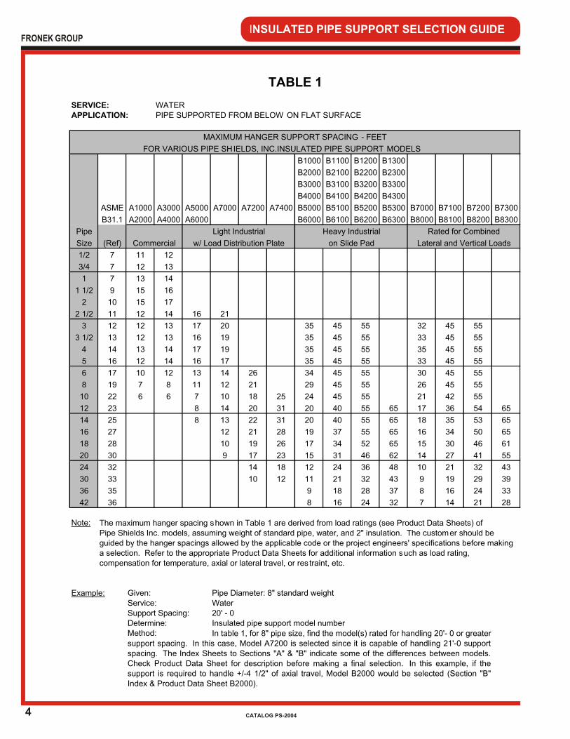
WATERPIPE SUPPORTED FROM BELOW ON FLAT SURFACE
B1000 B1100 B1200 B1300
B2000 B2100 B2200 B2300
B3000 B3100 B3200 B3300
B4000 B4100 B4200 B4300
ASME A1000 A3000 A5000 A7000 A7200 A7400 B5000 B5100 B5200 B5300 B7000 B7100 B7200 B7300
B31.1 A2000 A4000 A6000 B6000 B6100 B6200 B6300 B8000 B8100 B8200 B8300
Pipe
Size (Ref)
1/2 7 11 12
3/4 7 12 13
1 7 13 14
1 1/2 9 15 16
2 10 15 17
2 1/2 11 12 14 16 21
3 12 12 13 17 20 35 45 55 32 45 55
3 1/2 13 12 13 16 19 35 45 55 33 45 55
4 14 13 14 17 19 35 45 55 35 45 55
5 16 12 14 16 17 35 45 55 33 45 55
6 17 10 12 13 14 26 34 45 55 30 45 55
8 19 7 8 11 12 21 29 45 55 26 45 55
10 22 6 6 7 10 18 25 24 45 55 21 42 55
12 23 8 14 20 31 20 40 55 65 17 36 54 65
14 25 8 13 22 31 20 40 55 65 18 35 53 65
16 27 12 21 28 19 37 55 65 16 34 50 65
18 28 10 19 26 17 34 52 65 15 30 46 61
20 30 9 17 23 15 31 46 62 14 27 41 55
24 32 14 18 12 24 36 48 10 21 32 43
30 33 10 12 11 21 32 43 9 19 29 39
36 35 9 18 28 37 8 16 24 33
42 36 8 16 24 32 7 14 21 28
Note:
Pipe Diameter: 8" standard weightWater20' - 0Insulated pipe support model number
support spacing. In this case, Model A7200 is selected since it is capable of handling 21'-0 supportspacing. The Index Sheets to Sections "A" & "B" indicate some of the differences between models.Check Product Data Sheet for description before making a final selection. In this example, if thesupport is required to handle +/-4 1/2" of axial travel, Model B2000 would be selected (Section "B"Index & Product Data Sheet B2000).
The maximum hanger spacing s hown in Table 1 are derived from load ratings (see Product Data Sheets) of Pipe Shields Inc. models, assuming weight of standard pipe, water, and 2" insulation. The customer should be guided by the hanger spacings allowed by the applicable code or the project engineers' specifications before making a selection. Refer to the appropriate Product Data Sheets for additional information such as load rating, compensation for temperature, axial or lateral travel, or res traint, etc.
In table 1, for 8" pipe size, find the model(s) rated for handling 20'- 0 or greater
Service:
Determine:Support Spacing:
Method:
Example: Given:
TABLE 1
SERVICE:APPLICATION:
MAXIMUM HANGER SUPPORT SPACING - FEET
FOR VARIOUS PIPE SH IELDS, INC.INSULATED PIPE SUPPORT MODELS
Commercial
Light Industrial
w/ Load Distribution Plate
Heavy Industrial
on Slide Pad
Rated for Combined
Lateral and Vertical Loads
5
INSULATED PIPE SUPPORT SELECTION GUIDEFRONEK GROUP
CATALOG PS-2004
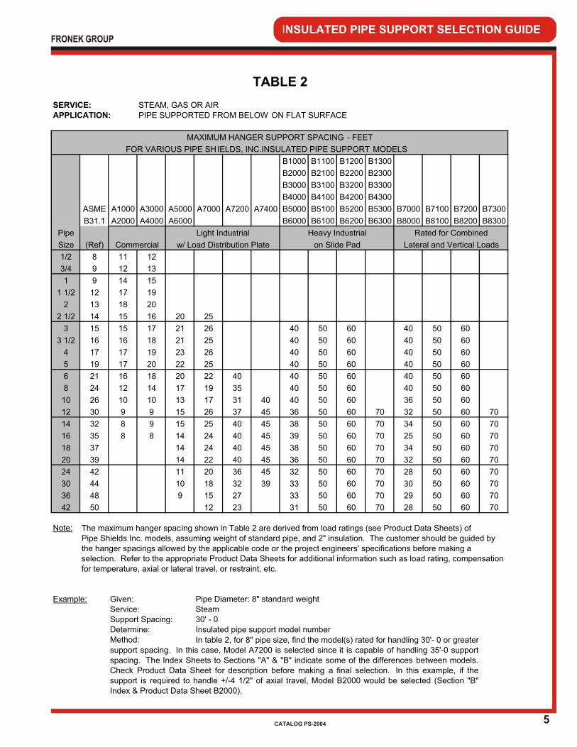
STEAM, GAS OR AIRPIPE SUPPORTED FROM BELOW ON FLAT SURFACE
B1000 B1100 B1200 B1300
B2000 B2100 B2200 B2300
B3000 B3100 B3200 B3300
B4000 B4100 B4200 B4300
ASME A1000 A3000 A5000 A7000 A7200 A7400 B5000 B5100 B5200 B5300 B7000 B7100 B7200 B7300
B31.1 A2000 A4000 A6000 B6000 B6100 B6200 B6300 B8000 B8100 B8200 B8300
Pipe
Size (Ref)
1/2 8 11 12
3/4 9 12 13
1 9 14 15
1 1/2 12 17 19
2 13 18 20
2 1/2 14 15 16 20 25
3 15 15 17 21 26 40 50 60 40 50 60
3 1/2 16 16 18 21 25 40 50 60 40 50 60
4 17 17 19 23 26 40 50 60 40 50 60
5 19 17 20 22 25 40 50 60 40 50 60
6 21 16 18 20 22 40 40 50 60 40 50 60
8 24 12 14 17 19 35 40 50 60 40 50 60
10 26 10 10 13 17 31 40 40 50 60 36 50 60
12 30 9 9 15 26 37 45 36 50 60 70 32 50 60 70
14 32 8 9 15 25 40 45 38 50 60 70 34 50 60 70
16 35 8 8 14 24 40 45 39 50 60 70 25 50 60 70
18 37 14 24 40 45 38 50 60 70 34 50 60 70
20 39 14 22 40 45 36 50 60 70 32 50 60 70
24 42 11 20 36 45 32 50 60 70 28 50 60 70
30 44 10 18 32 39 33 50 60 70 30 50 60 70
36 48 9 15 27 33 50 60 70 29 50 60 70
42 50 12 23 31 50 60 70 28 50 60 70
Note:
Pipe Diameter: 8" standard weightSteam30' - 0Insulated pipe support model number
The maximum hanger spac ing shown in Table 2 are derived from load ratings (see Product Data Sheets) of Pipe Shields Inc. models, assuming weight of standard pipe, and 2" insulation. The customer should be guided by the hanger spacings allowed by the applicable code or the project engineers' specifications before making a selection. Refer to the appropriate Product Data Sheets for additional information such as load rating, compensation for temperature, axial or lateral travel, or restraint, etc.
w/ Load Distribution Plate
Heavy Industrial
on Slide Pad
Rated for Combined
Lateral and Vertical Loads
support spacing. In this case, Model A7200 is selected since it is capable of handling 35'-0 supportspacing. The Index Sheets to Sections "A" & "B" indicate some of the differences between models.Check Product Data Sheet for description before making a final selection. In this example, if thesupport is required to handle +/-4 1/2" of axial travel, Model B2000 would be selected (Section "B"Index & Product Data Sheet B2000).
Example: Given:
TABLE 2
SERVICE:APPLICATION:
MAXIMUM HANGER SUPPORT SPACING - FEET
FOR VARIOUS PIPE SH IELDS, INC.INSULATED PIPE SUPPORT MODELS
Commercial
Light Industrial
In table 2, for 8" pipe size, find the model(s) rated for handling 30'- 0 or greater
Service:
Determine:Support Spacing:
Method:

6
INSULATED PIPE SUPPORT SELECTION GUIDEFRONEK GROUP
CATALOG PS-2004
WATERPIPE SUPPORTED FROM ABOVE IN CLEVIS OR 2-BOLT HANGER
D1000
D2000
ASME A1000 A3000 D4000 D3000 D3100 D3200 D3300
B31.1 A2000 A4000 A9000 D5000 D6000 D6100 D6200 D6300
Pipe
Size (Ref)
1/2 7 11 12 13
3/4 7 12 13 15
1 7 14 15 17 19
1 1/2 9 16 18 19 22
2 10 17 18 21 29
2 1/2 11 16 18 21 24
3 12 17 18 20 25
3 1/2 13 16 17 19 22
4 14 16 18 19 22
5 16 15 16 19 21 40
6 17 14 15 16 21 40
8 19 13 13 15 22 32
10 22 12 13 14 24 28
12 23 11 12 13 22 26
14 25 11 12 13 20 23
16 27 10 11 12 21 26 40
18 28 9 10 11 18 22 33
20 30 9 9 10 16 18 28 37
24 32 8 9 15 19 29 38
30 33 11 13 19 26
Note:
Pipe Diameter: 8" standard weightWater20' - 0Insulated pipe support model number
MAXIMUM HANGER SUPPORT SPACING - FEET
In table 3, for 8" pipe size, find the model(s) rated for handling 20"- 0 or greatersupport spacing. In this case, Model D3000 is selected since it is capable of handling 22'-0 support spacing.The Index Sheets to Sections "A" & "D" indicate some of the differences between models. Check ProductData Sheet for description before making a final selection. In this example, if the clearance is above thesupport limited, Model D6000 might be selected (Section "D" Index & Product Data Sheet D6000).
Service:
Determine:Support Spacing:
Method:
Example: Given:
The maximum hanger spacing shown in Table 3 are derived from load ratings (see Product Data Sheets) ofPipe Shields Inc. models, assuming weight of standard pipe, water, and 2" insulation. The customer should beguided by the hanger spacings allowed by the applicable code or the project engineers' specifications before makingaection. Refer to the appropriate Product Data Sheets for additional information such as load rating,compensation for temperature, axial or lateral travel, or res traint, etc.
TABLE 3
SERVICE:APPLICATION:
Clevis Hanger 2-Bolt Hanger
FOR VARIOUS PIPE SH IELDS, INC.
PRE-INSULATED PIPE SUPPORT MODELS
7
INSULATED PIPE SUPPORT SELECTION GUIDEFRONEK GROUP
CATALOG PS-2004
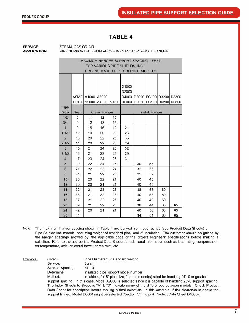
STEAM, GAS OR AIRPIPE SUPPORTED FROM ABOVE IN CLEVIS OR 2-BOLT HANGER
D1000
D2000
ASME A1000 A3000 D4000 D3000 D3100 D3200 D3300
B31.1 A2000 A4000 A9000 D5000 D6000 D6100 D6200 D6300
Pipe
Size (Ref)
1/2 8 11 12 13
3/4 9 12 13 15
1 9 15 16 19 21
1 1/2 12 19 20 22 26
2 13 20 22 25 36
2 1/2 14 20 22 25 29
3 15 21 24 26 32
3 1/2 16 21 23 25 29
4 17 23 24 26 31
5 19 22 24 28 30 55
6 21 22 23 24 32 55
8 24 21 22 25 25 52
10 26 20 22 24 40 45
12 30 20 21 24 40 45
14 32 21 23 25 38 55 60
16 35 21 22 25 40 55 60
18 37 21 22 25 40 49 60
20 39 21 22 25 38 44 60 65
24 42 20 21 24 40 50 60 65
30 44 34 51 60 65
Note:
Pipe Diameter: 8" standard weightSteam24' - 0Insulated pipe support model number
TABLE 4
SERVICE:APPLICATION:
Clevis Hanger
FOR VARIOUS PIPE SH IELDS, INC.
PRE-INSULATED PIPE SUPPORT MODELS
2-Bolt Hanger
MAXIMUM HANGER SUPPORT SPACING - FEET
The maximum hanger spacing shown in Table 4 are derived from load ratings (see Product Data Sheets) oPipe Shields Inc. models, assuming weight of standard pipe, and 2" insulation. The customer should be guided bythe hanger spacings allowed by the applicable code or the project engineers' specifications before making aselection. Refer to the appropriate Product Data Sheets for additional information such as load rating, compensationfor temperature, axial or lateral travel, or restraint, etc.
support spacing. In this case, Model A9000 is selected since it is capable of handling 25'-0 support spacing.The Index Sheets to Sections "A" & "D" indicate some of the differences between models. Check ProductData Sheet for description before making a final selection. In this example, if the clearance is above thesupport limited, Model D6000 might be selected (Section "D" Index & Product Data Sheet D6000).
Service:
Determine:Support Spacing:
Method: In table 4, for 8" pipe size, find the model(s) rated for handling 24'- 0 or greater
Example: Given:
8
INSULATED PIPE SUPPORT SELECTION GUIDEFRONEK GROUP
CATALOG PS-2004
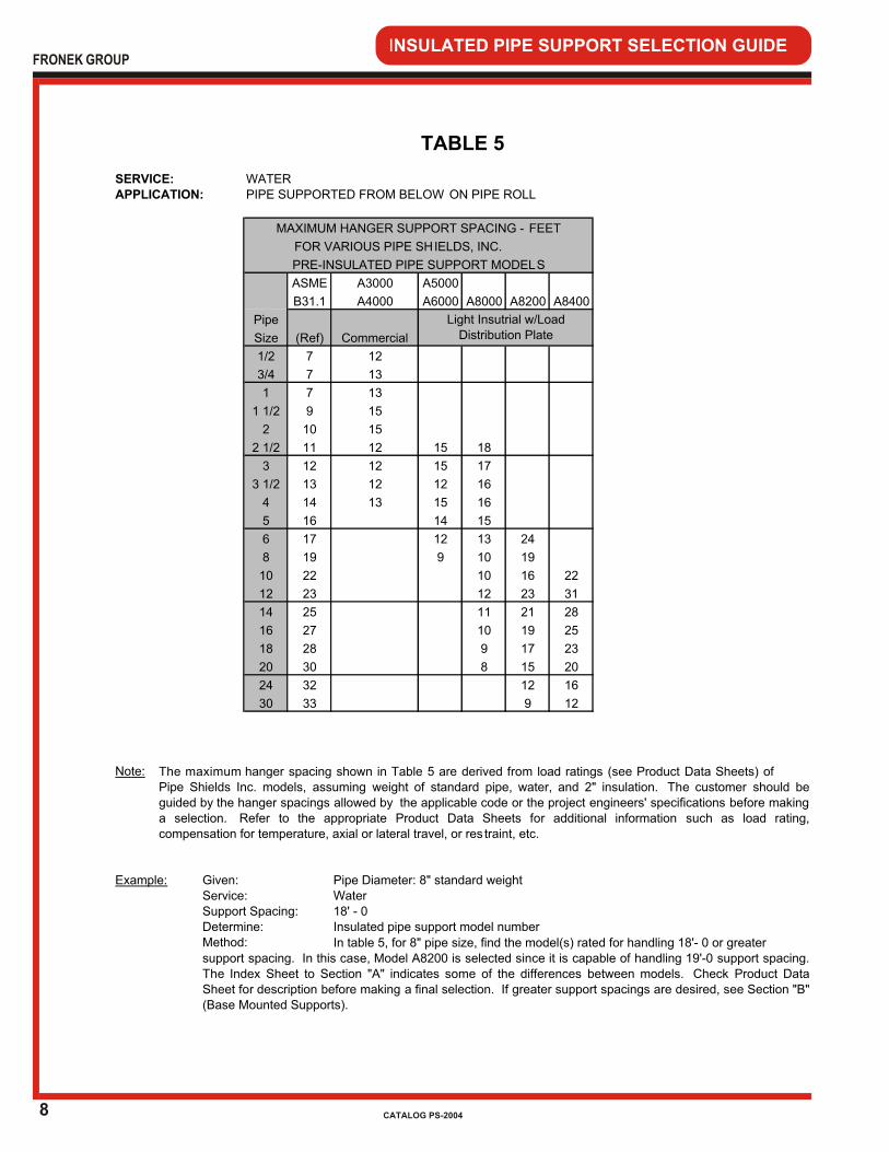
WATERPIPE SUPPORTED FROM BELOW ON PIPE ROLL
ASME A5000
B31.1 A6000 A8000 A8200 A8400
Pipe
Size (Ref)
1/2 7
3/4 7
1 7
1 1/2 9
2 10
2 1/2 11 15 18
3 12 15 17
3 1/2 13 12 16
4 14 15 16
5 16 14 15
6 17 12 13 24
8 19 9 10 19
10 22 10 16 22
12 23 12 23 31
14 25 11 21 28
16 27 10 19 25
18 28 9 17 23
20 30 8 15 20
24 32 12 16
30 33 9 12
Note:
Pipe Diameter: 8" standard weightWater18' - 0Insulated pipe support model number
The maximum hanger spacing shown in Table 5 are derived from load ratings (see Product Data Sheets) ofPipe Shields Inc. models, assuming weight of standard pipe, water, and 2" insulation. The customer should beguided by the hanger spacings allowed by the applicable code or the project engineers' specifications before makinga selection. Refer to the appropriate Product Data Sheets for additional information such as load rating,compensation for temperature, axial or lateral travel, or res traint, etc.
13
15
12
12
12
Service:
Determine:Support Spacing:
Method: In table 5, for 8" pipe size, find the model(s) rated for handling 18'- 0 or greatersupport spacing. In this case, Model A8200 is selected since it is capable of handling 19'-0 support spacing.The Index Sheet to Section "A" indicates some of the differences between models. Check Product DataSheet for description before making a final selection. If greater support spacings are desired, see Section "B"(Base Mounted Supports).
Example: Given:
TABLE 5
SERVICE:APPLICATION:
A3000
A4000
13
15
Commercial
12
13
Light Insutrial w/Load Distribution Plate
MAXIMUM HANGER SUPPORT SPACING - FEET
FOR VARIOUS PIPE SH IELDS, INC.
PRE-INSULATED PIPE SUPPORT MODELS
9
INSULATED PIPE SUPPORT SELECTION GUIDEFRONEK GROUP
CATALOG PS-2004
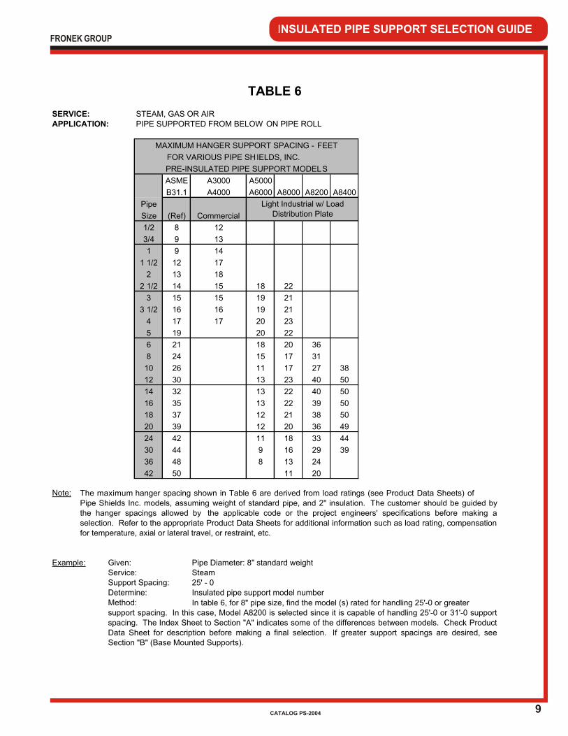
STEAM, GAS OR AIRPIPE SUPPORTED FROM BELOW ON PIPE ROLL
ASME A5000
B31.1 A6000 A8000 A8200 A8400
Pipe
Size (Ref)
1/2 8
3/4 9
1 9
1 1/2 12
2 13
2 1/2 14 18 22
3 15 19 21
3 1/2 16 19 21
4 17 20 23
5 19 20 22
6 21 18 20 36
8 24 15 17 31
10 26 11 17 27 38
12 30 13 23 40 50
14 32 13 22 40 50
16 35 13 22 39 50
18 37 12 21 38 50
20 39 12 20 36 49
24 42 11 18 33 44
30 44 9 16 29 39
36 48 8 13 24
42 50 11 20
Note:
Pipe Diameter: 8" standard weightSteam25' - 0Insulated pipe support model number
Light Industrial w/ Load Distribution Plate
15
Example: Given:
15
16
17
The maximum hanger spacing shown in Table 6 are derived from load ratings (see Product Data Sheets) of
Pipe Shields Inc. models, assuming weight of standard pipe, and 2" insulation. The customer should be guided bythe hanger spacings allowed by the applicable code or the project engineers' specifications before making aselection. Refer to the appropriate Product Data Sheets for additional information such as load rating, compensationfor temperature, axial or lateral travel, or restraint, etc.
TABLE 6
SERVICE:APPLICATION:
A3000
MAXIMUM HANGER SUPPORT SPACING - FEET
FOR VARIOUS PIPE SH IELDS, INC.
PRE-INSULATED PIPE SUPPORT MODELS
A4000
14
17
18
Commercial
12
13
Service:
Determine:Support Spacing:
Method: In table 6, for 8" pipe size, find the model (s) rated for handling 25'-0 or greatersupport spacing. In this case, Model A8200 is selected since it is capable of handling 25'-0 or 31'-0 supportspacing. The Index Sheet to Section "A" indicates some of the differences between models. Check ProductData Sheet for description before making a final selection. If greater support spacings are desired, seeSection "B" (Base Mounted Supports).
FRONEK GROUP
INTRODUCTION SECTION “A”
INTRODUCTION
SECTION “A”
PRE-INSULATED PIPE SUPPORTS
APPLICATION – Commercial and Light Industrial Most Commercial applications are well served by Models A1000 and A2000, which are recommended for use on common 10’-0 hanger space for small bore pipe sizes (see Selection Guide). However, should the need arise, because of increased hanger spacing or the manner in which the insulated support is mounted, heavier duty supports are available. As is readily seen in the “Section Index” on the following page, some models are meant for installation only in a clevis hanger, on a flat surface, or on a pipe roll. Other models may be installed in any two or all three mounting methods. The load ratings (see Product Data Sheets) reflect consideration for the manner in which each of these models will be mounted. Note that in the A7000 through A7400 Series and the A8000 through A8400 Series, the higher the model number, the higher the load rating. We are committed to providing the most economical and appropriate insulated pipe support to satisfy the requirements of the piping system.
If your requirements are not covered by the Product Data Sheets in this catalog, please contact us at 713-731-0030 or 1-800-787-5914.
Please acquaint yourself with the selection guide at the front of this catalog and the section index on the page following this introduction, for assistance in determining the most
appropriate support for your application.
FRONEK GROUP
CATALOG PS-2004

PIPE
SIZE FLAT CLEVIS PIPE
MODEL RANGE HOT COLD SURFACE HANGER ROLL DUTY
A1000 1/2 - 24 X X X LIGHT
A2000 1/2 - 24 X X X LIGHT
A3000 1/2 - 24 X X X MEDIUM
A3000 1/2 - 4 X X MEDIUM
A4000 1/2 - 24 X X X MEDIUM
A4000 1/2 - 4 X X MEDIUM
A5000 2 1/2 - 42 X X X MED/HEAVY
A6000 2 1/2 - 42 X X X MED/HEAVY
A7000 2 1/2 - 42 X X X HEAVY
A7200 6 - 42 X X X HEAVIER
A7400 10 - 30 X X X HEAVIEST
A8000 2 1/2 - 42 X X X HEAVY
A8200 6 - 42 X X X HEAVIER
A8400 10 - 30 X X X HEAVIEST
A9000 1/2 - 24 X X X HEAVY
PRE-INSULATED PIPE SUPPORTS
COMMERCIAL AND LIGHT INDUSTRIAL
PRIMARY
APPLICATION
INSTALLED ON
SECTION “A” INDEX
TO ORDER, specify:1. Quantity 202. Pipe Size & Type 2” IPS3. Insulation Thickness 2-1/2”4. Model Number A1000
EXAMPLE: (20) 2 x 2-1/2 A1000
FRONEK GROUP
CATALOG PS-2004
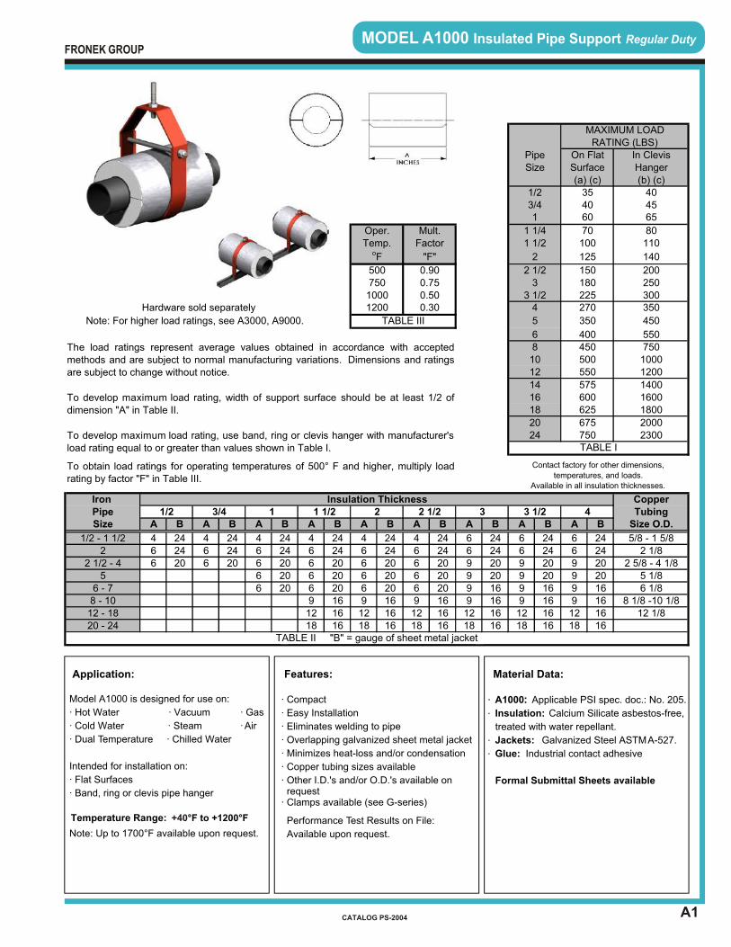
MODEL A1000 Insulated Pipe Support Regular Duty
A1
Features:
· Compact
· Easy Installation
· Eliminates welding to pipe
· Overlapping galvanized sheet metal jacket
· Minimizes heat-loss and/or condensation
· Copper tubing sizes available
· Other I.D.'s and/or O.D.'s available on request· Clamps available (see G-series)
Performance Test Results on File:
Available upon request.
· ·
·
·
Material Data:
A1000: Applicable PSI spec. doc.: No. 205.
Insulation: Calcium Silicate asbestos-free,
treated with water repellant.
Jackets: Galvanized Steel ASTM A-527.
Glue: Industrial contact adhesive
Formal Submittal Sheets available
Application:
Model A1000 is designed for use on:
· Hot Water · Vacuum · Gas
· Cold Water · Steam · Air
· Dual Temperature · Chilled Water
Intended for installation on:
· Flat Surfaces
· Band, ring or clevis pipe hanger
Note: Up to 1700°F available upon request.
Temperature Range: °F to +1200°F +40
FRONEK GROUP
CATALOG PS-2004
Hardware sold separately
A B A B A B A B A B A B A B A B A B
4 24 4 24 4 24 4 24 4 24 4 24 6 24 6 24 6 246 24 6 24 6 24 6 24 6 24 6 24 6 24 6 24 6 246 20 6 20 6 20 6 20 6 20 6 20 9 20 9 20 9 20
6 20 6 20 6 20 6 20 9 20 9 20 9 206 20 6 20 6 20 6 20 9 16 9 16 9 16
9 16 9 16 9 16 9 16 9 16 9 1612 16 12 16 12 16 12 16 12 16 12 1618 16 18 16 18 16 18 16 18 16 18 16
200
TABLE III
1200
0.750.500.30
7501000
350
450
Mult.
CopperTubing
Size O.D.
250
5501000750
1200
300
Oper.Temp.
oF
To develop maximum load rating, use band, ring or clevis hanger with manufacturer'sload rating equal to or greater than values shown in Table I.
To develop maximum load rating, width of support surface should be at least 1/2 ofdimension "A" in Table II.
The load ratings represent average values obtained in accordance with acceptedmethods and are subject to normal manufacturing variations. Dimensions and ratingsare subject to change without notice.
Factor
"F"
500 0.90
MAXIMUM LOAD
Pipe On Flat In Clevis
1 1/2Iron
Contact factory for other dimensions,
temperatures, and loads.
Available in all insulation thicknesses.
Insulation Thickness2 2 1/2
To obtain load ratings for operating temperatures of 500° F and higher, multiply loadrating by factor "F" in Table III.
1/2 3/4 1
8 1/8 -10 1/812 1/8
5/8 - 1 5/8
4
2 1/82 5/8 - 4 1/8
550
350
65
80110
140
150180225270
400450
3
8
5
6
141618
2420
16001800
2000
3 1/2
TABLE I750
600625
675
TABLE II "B" = gauge of sheet metal jacket
PipeSize
1/2 - 1 1/2
6 - 78 - 1012 - 18
52 1/2 - 4
3
2 1/2
2
20 - 24
5 1/86 1/8
2300
10
1400575
500
Note: For higher load ratings, see A3000, A9000.
12
3 1/24
70100
125
1 1/41 1/2
2
1
1/24060
Size
3/4
RATING (LBS)
Hanger(b) (c)
40
Surface(a) (c)
3545

A2
MODEL A2000 Insulated Pipe Support Regular Duty w/Extended Insulation
Application:
Model A2000 is designed for use on:
· Cold Water
· Chilled Water
Intended for installation on:
· Flat Surfaces
· Band, ring or clevis pipe hangers
Temperature Range: °F to +1200°F +40
Note: Up to 1700°F available upon request.
Features:
· Compact
· Easy Installation
· Eliminates welding to pipe
· Overlapping galvanized sheet metal jacket
· Minimizes heat-loss and/or condensation
· Calcium silicate insulation extends 1'' beyond
the galvanized sheet metal jacket providing
for an easier vapor barrier joint with the pipe
insulation
· Copper tubing sizes available
· Other I.D.'s and/or O.D.'s available on request· Clamps available see (G-series)
Performance Test Results on File:
Available upon request.
Material Data:
· A2000: Applicable PSI spec. doc.: No. 205.
· Insulation: Calcium Silicate asbestos-free,
treated with water repellant.
· Jackets: Galvanized Steel ASTM A-527.
· Glue: Industrial contact adhesive
Formal Submittal Sheets available
FRONEK GROUP
CATALOG PS-2004
Hardware sold separately
A B A B A B A B A B A B A B A B A B
6 24 6 24 6 24 6 24 6 24 6 24 6 24 6 24 6 246 24 6 24 6 24 6 24 6 24 6 24 6 24 6 24 6 246 20 6 20 6 20 6 20 6 20 6 20 9 20 9 20 9 20
6 20 6 20 6 20 6 20 9 20 9 20 9 206 20 6 20 6 20 6 20 9 16 9 16 9 16
9 16 9 16 9 16 9 16 9 16 9 1612 16 12 16 12 16 12 16 12 16 12 1618 16 18 16 18 16 18 16 18 16 18 16
0.750.50
TABLE III
1200 0.30
FactorTemp.
The load ratings represent average values obtained in accordance with acceptedmethods and are subject to normal manufacturing variations. Dimensions and ratingsare subject to change without notice.
oF "F"
Note: For higher load ratings, see A4000, A9000.
5007501000
0.90
10
3 1/2
1214
4
5
68
To obtain load ratings for operating temperatures of 500°F and higher, multiply loadrating by factor "F" in Table III.
182024
To develop maximum load rating, width of support surface should be at least 1/2 ofdimension "A" in Table II.
To develop maximum load rating, use band, ring or clevis hanger with manufacturer'sload rating equal to or greater than values shown in Table I.
Contact factory for other dimensions,
temperatures, and loads.
Available in all insulation thicknesses.
16
2000675
14001600
1800625
575
1 1/2
2
2 1/23
1/23/41
1 1/4
12 1/8
750
5/8 - 15/8
CopperTubing
Size O.D.4
2300
6 1/88 1/8 -10 1/8
110
140
200250
450
7501000
550
70
600
500
150
400450
550
MAXIMUM LOAD
On Flat
1200
Pipe
225270
100
125
300350
3 1/2
RATING (LBS)In Clevis
404565
80
354060
Oper. Mult.
2 2 1/2Insulation ThicknessIron
Pipe
180
350
TABLE II "B" = gauge of sheet metal jacket
3/4 1 1 1/2
20 - 24
56 - 7
2 1/82 5/8 - 4 1/8
5 1/8
1/2 - 1 1/2
1/2
8 - 10
Size
12 - 18
Size
TABLE I
Hanger(b) (c)
Surface(a) (c)
2 1/2 - 4
3
2
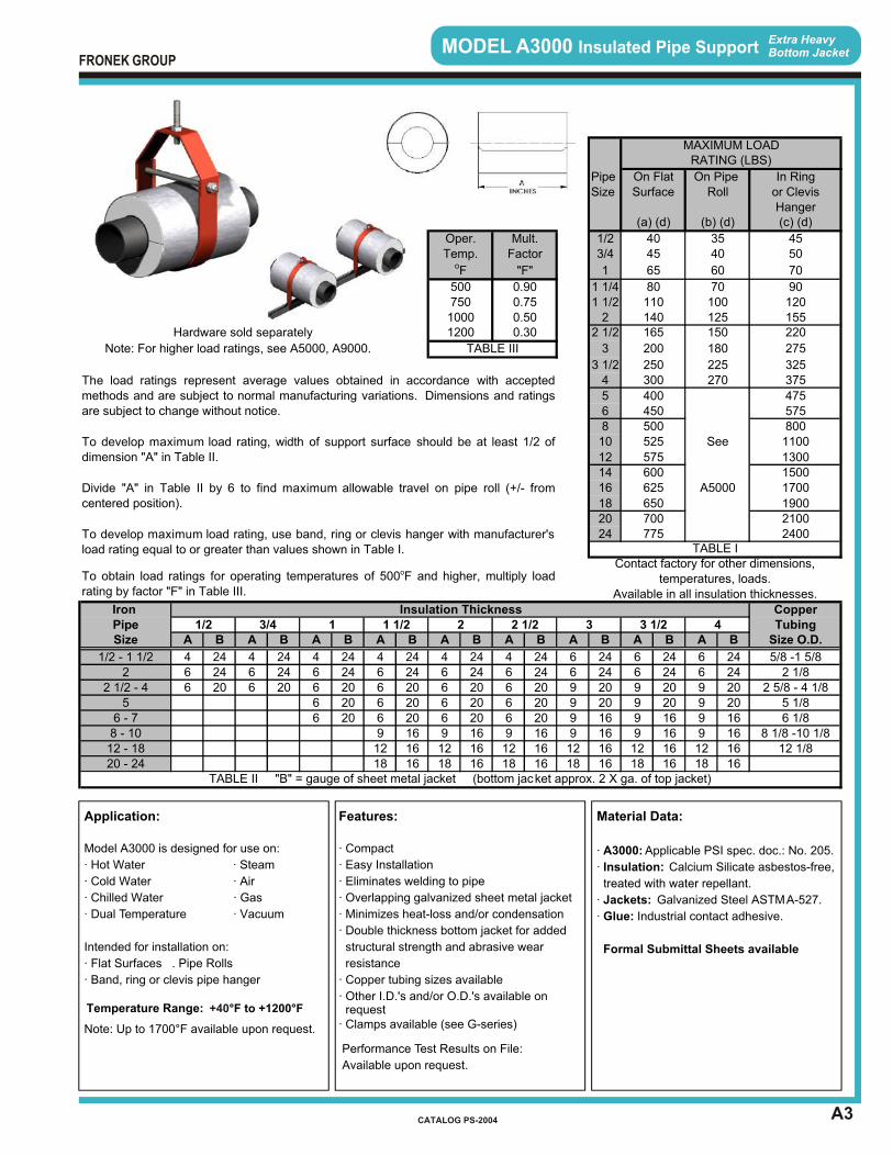
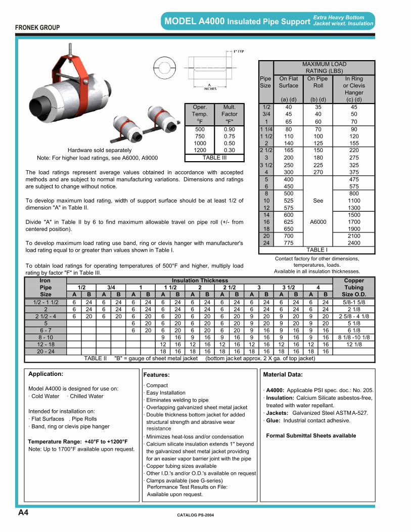
MODEL A3000 Insulated Pipe Support
A3
Extra HeavyBottom Jacket
Features:
· Compact
· Easy Installation
· Eliminates welding to pipe
· Overlapping galvanized sheet metal jacket
· Minimizes heat-loss and/or condensation
· Double thickness bottom jacket for added
structural strength and abrasive wear
resistance
· Copper tubing sizes available
· Other I.D.'s and/or O.D.'s available on request· Clamps available (see G-series)
Performance Test Results on File:
Available upon request.
Material Data:
· A3000: Applicable PSI spec. doc.: No. 205.
· Insulation: Calcium Silicate asbestos-free,
treated with water repellant.
· Jackets: Galvanized Steel ASTM A-527.
· Glue: Industrial contact adhesive.
Formal Submittal Sheets available
Application:
Model A3000 is designed for use on:
· Hot Water · Steam
· Cold Water · Air
· Chilled Water · Gas
· Dual Temperature · Vacuum
Intended for installation on:
· Flat Surfaces . Pipe Rolls
· Band, ring or clevis pipe hanger
Note: Up to 1700°F available upon request.
Temperature Range: °F to +1200°F +40
FRONEK GROUP
CATALOG PS-2004
PipeSize
1/23/4
1
1 1/41 1/2
2Hardware sold separately 2 1/2
3
3 1/24
56810
121416
182024
A B A B A B A B A B A B A B A B A B
4 24 4 24 4 24 4 24 4 24 4 24 6 24 6 24 6 246 24 6 24 6 24 6 24 6 24 6 24 6 24 6 24 6 246 20 6 20 6 20 6 20 6 20 6 20 9 20 9 20 9 20
6 20 6 20 6 20 6 20 9 20 9 20 9 206 20 6 20 6 20 6 20 9 16 9 16 9 16
9 16 9 16 9 16 9 16 9 16 9 1612 16 12 16 12 16 12 16 12 16 12 1618 16 18 16 18 16 18 16 18 16 18 16
TABLE II "B" = gauge of sheet metal jacket (bottom jacket approx. 2 X ga. of top jacket)
12 - 18 12 1/820 - 24
6 - 7 6 1/88 - 10 8 1/8 -10 1/8
2 1/2 - 4 2 5/8 - 4 1/85 5 1/8
1/2 - 1 1/2 5/8 -1 5/82 2 1/8
3 1/2 4 TubingSize Size O.D.
1 1/2 2 2 1/2 3Pipe
To develop maximum load rating, use band, ring or clevis hanger with manufacturer'sload rating equal to or greater than values shown in Table I. TABLE I
1/2 3/4 1
Contact factory for other dimensions, temperatures, loads.
Available in all insulation thicknesses.
To obtain load ratings for operating temperatures of 500oF and higher, multiply loadrating by factor "F" in Table III.
Iron Insulation Thickness Copper
700 2100775 2400
Divide "A" in Table II by 6 to find maximum allowable travel on pipe roll (+/- fromcentered position). 650 1900
600 1500625 A5000 1700
To develop maximum load rating, width of support surface should be at least 1/2 ofdimension "A" in Table II. 575 1300
500 800525 See 1100
300 270 375The load ratings represent average values obtained in accordance with acceptedmethods and are subject to normal manufacturing variations. Dimensions and ratingsare subject to change without notice.
400 475450 575
Note: For higher load ratings, see A5000, A9000.
250 225 325
200 180
155
TABLE III
165 150 2201200 0.30140 125
275
120750 0.7580
1000 0.50110 100
50
500 0.90
65 60 70
70 90
(b) (d) (c) (d)
Temp. Factor40 35 45Oper. Mult.
40
(a) (d)
oF "F"
45
Surface Roll or ClevisHanger
MAXIMUM LOADRATING (LBS)
On Flat On Pipe In Ring
A4
MODEL A4000 Insulated Pipe Support Extra Heavy BottomJacket w/ext. Insulation
Material Data:
· A4000: Applicable PSI spec. doc.: No. 205.
· Insulation: Calcium Silicate asbestos-free,
treated with water repellant.
· Jackets: Galvanized Steel ASTM A-527.
· Glue: Industrial contact adhesive.
Formal Submittal Sheets available
Features:
· Compact
· Easy Installation
· Eliminates welding to pipe
· Overlapping galvanized sheet metal jacket
· Double thickness bottom jacket for added
structural strength and abrasive wear
· Minimizes heat-loss and/or condensation
· Calcium silicate insulation extends 1'' beyond
the galvanized sheet metal jacket providing
for an easier vapor barrier joint with the pipe
· Copper tubing sizes available
· Other I.D.'s and/or O.D.'s available on request
· Clamps available (see G-series)
Performance Test Results on File:
Available upon request.
resistance
Application:
Model A4000 is designed for use on:
· Cold Water · Chilled Water
Intended for installation on:
· Flat Surfaces . Pipe Rolls
· Band, ring or clevis pipe hanger
Note: Up to 1700°F available upon request.
Temperature Range: °F to +1200°F +40
FRONEK GROUP
CATALOG PS-2004
PipeSize
1/23/4
1
1 1/41 1/2
2Hardware sold separately 2 1/2
3
3 1/24
568
10
121416
182024
A B A B A B A B A B A B A B A B A B
6 24 6 24 6 24 6 24 6 24 6 24 6 24 6 24 6 246 24 6 24 6 24 6 24 6 24 6 24 6 24 6 24 6 246 20 6 20 6 20 6 20 6 20 6 20 9 20 9 20 9 20
6 20 6 20 6 20 6 20 9 20 9 20 9 206 20 6 20 6 20 6 20 9 16 9 16 9 16
9 16 9 16 9 16 9 16 9 16 9 1612 16 12 16 12 16 12 16 12 16 12 1618 16 18 16 18 16 18 16 18 16 18 16
3540
12 1/8
5/8-1 5/8
2 5/8 - 4 1/8
6 1/88 1/8 -10 1/8
See
270
60
70100125
80110140165
Surface
4045
65
On Pipe In Ring
(c) (d)
or ClevisRoll
Temp.Oper. Mult.
Factor
12 - 18
2 1/2 - 4
TABLE III
2 2 1/2Iron PipeSize
1/2
21/2 - 1 1/2
TABLE II "B" = gauge of sheet metal jacket (bottom jacket approx. 2 X ga. of top jacket)
3/4 1 1 1/2
20 - 24
56 - 78 - 10
220
275200
250
150
180
225 325
1200
0.900.750.500.30
500
"F"
7501000
oF 70
90120155
MAXIMUM LOAD
On Flat
375
475
45
Hanger(b) (d)
RATING (LBS)
(a) (d)
50
575
3 1/2
1700190021002400
4Insulation Thickness
700
300
400450
650
500
625
525
575600
5 1/8
CopperTubing
Size O.D.
1500
775
2 1/8
TABLE I
3
A6000
Note: For higher load ratings, see A6000, A9000
To obtain load ratings for operating temperatures of 500°F and higher, multiply loadrating by factor "F" in Table III.
Contact factory for other dimensions, temperatures, loads.
Available in all insulation thicknesses.
The load ratings represent average values obtained in accordance with acceptedmethods and are subject to normal manufacturing variations. Dimensions and ratingsare subject to change without notice.
To develop maximum load rating, width of support surface should be at least 1/2 ofdimension "A" in Table II.
Divide "A" in Table II by 6 to find maximum allowable travel on pipe roll (+/- fromcentered position).
To develop maximum load rating use band, ring or clevis hanger with manufacturer'sload rating equal to or greater than values shown in Table I.
800
1100
1300
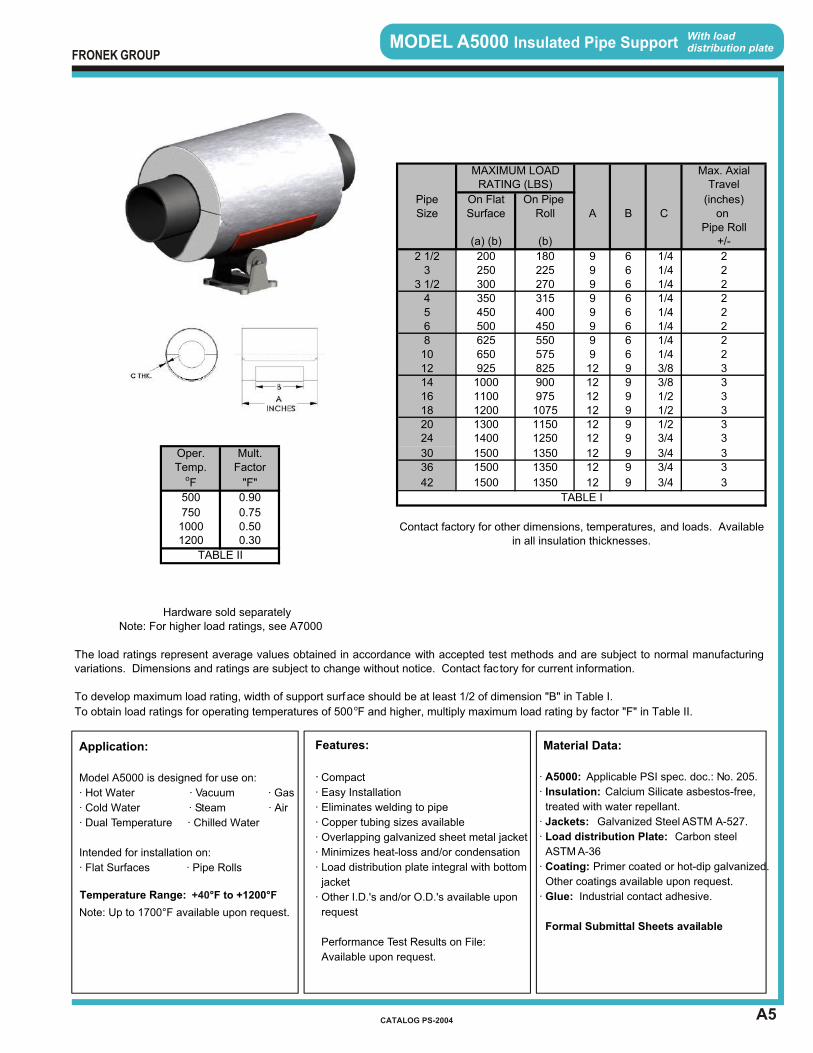
A5
MODEL A5000 Insulated Pipe Support With loaddistribution plate
Features:
· Compact
· Easy Installation
· Eliminates welding to pipe
· Copper tubing sizes available
· Overlapping galvanized sheet metal jacket
· Minimizes heat-loss and/or condensation
· Load distribution plate integral with bottom
jacket
· Other I.D.'s and/or O.D.'s available upon
request
Performance Test Results on File:
Available upon request.
Material Data:
· A5000: Applicable PSI spec. doc.: No. 205.
· Insulation: Calcium Silicate asbestos-free,
treated with water repellant.
· Jackets: Galvanized Steel ASTM A-527.
· Load distribution Plate: Carbon steel ASTM A-36
· Coating: Primer coated or hot-dip galvanized.
Other coatings available upon request.
· Glue: Industrial contact adhesive.
Formal Submittal Sheets available
Application:
Model A5000 is designed for use on:
· Hot Water · Vacuum · Gas
· Cold Water · Steam · Air
· Dual Temperature · Chilled Water
Intended for installation on:
· Flat Surfaces · Pipe Rolls
Note: Up to 1700°F available upon request.
Temperature Range: °F to +1200°F +40
FRONEK GROUP
CATALOG PS-2004
A B C
9 6 1/49 6 1/49 6 1/49 6 1/49 6 1/49 6 1/49 6 1/49 6 1/412 9 3/812 9 3/812 9 1/212 9 1/212 9 1/212 9 3/4
12 9 3/412 9 3/4
12 9 3/4
Hardware sold separatelyNote: For higher load ratings, see A7000
The load ratings represent average values obtained in accordance with accepted test methods and are subject to normal manufacturingvariations. Dimensions and ratings are subject to change without notice. Contact fac tory for current information.
To develop maximum load rating, width of support surface should be at least 1/2 of dimension "B" in Table I.
To obtain load ratings for operating temperatures of 500 oF and higher, multiply maximum load rating by factor "F" in Table II.
Contact factory for other dimensions, temperatures, and loads. Available in all insulation thicknesses.1200 0.30
TABLE II
750 0.751000 0.50
1350 3
500 0.90 TABLE I
oF "F" 42 1500
1350 3Temp. Factor 36 1500 1350 3Oper. Mult. 30 1500
24 1400 1250 320 1300 1150 318 1200 1075 316 1100 975 314 1000 900 312 925 825 310 650 575 28 625 550 26 500 450 25 450 400 24 350 315 2
3 1/2 300 270 23 250 225 2
2 1/2 200 180 2
Pipe Roll(a) (b) (b) +/-
Size Surface Roll on Pipe On Flat On Pipe (inches)
MAXIMUM LOAD Max. AxialRATING (LBS) Travel
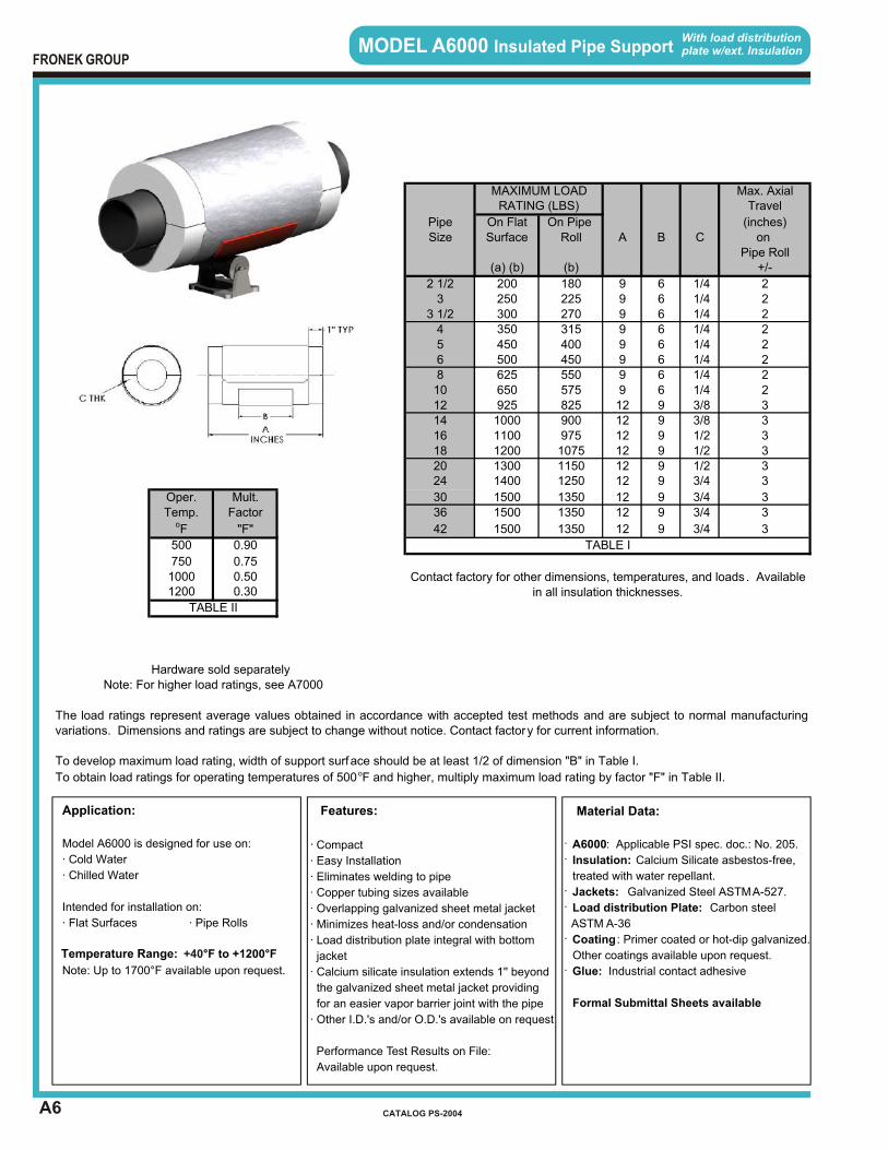
With load distributionplate w/ext. InsulationMODEL A6000 Insulated Pipe Support
A6
Features:
· Compact
· Easy Installation
· Eliminates welding to pipe
· Copper tubing sizes available
· Overlapping galvanized sheet metal jacket
· Minimizes heat-loss and/or condensation
· Load distribution plate integral with bottom
jacket
· Calcium silicate insulation extends 1'' beyond
the galvanized sheet metal jacket providing
for an easier vapor barrier joint with the pipe
· Other I.D.'s and/or O.D.'s available on request
Performance Test Results on File:
Available upon request.
·
·
·
·
·
·
Material Data:
A6000: Applicable PSI spec. doc.: No. 205.
Insulation: Calcium Silicate asbestos-free,
treated with water repellant.
Jackets: Galvanized Steel ASTM A-527.
Load distribution Plate: Carbon steel
ASTM A-36
Coating : Primer coated or hot-dip galvanized.
Other coatings available upon request.
Glue: Industrial contact adhesive
Formal Submittal Sheets available
Application:
Model A6000 is designed for use on:
· Cold Water
· Chilled Water
Intended for installation on:
· Flat Surfaces · Pipe Rolls
Note: Up to 1700°F available upon request.
Temperature Range: °F to +1200°F +40
FRONEK GROUP
CATALOG PS-2004
A B C
9 6 1/49 6 1/49 6 1/49 6 1/49 6 1/49 6 1/49 6 1/49 6 1/412 9 3/812 9 3/812 9 1/212 9 1/212 9 1/212 9 3/4
12 9 3/412 9 3/4
12 9 3/4
Hardware sold separately
MAXIMUM LOAD Max. AxialRATING (LBS) Travel
Pipe On Flat On Pipe (inches)Size Surface Roll on
Pipe Roll(a) (b) (b) +/-
2 1/2 200 180 23 250 225 2
3 1/2 300 270 24 350 315 25 450 400 26 500 450 28 625 550 210 650 575 212 925 825 314 1000 900 316 1100 975 318 1200 1075 3
1250 320 1300 1150 3
30 1500
24 1400
1350 3Temp. Factor 36 1500 1350 3Oper. Mult.
1350 3
500 0.90 TABLE I
oF "F" 42 1500
750 0.751000 0.50 Contact factory for other dimensions, temperatures, and loads . Available
in all insulation thicknesses.1200 0.30
TABLE II
Note: For higher load ratings, see A7000
The load ratings represent average values obtained in accordance with accepted test methods and are subject to normal manufacturingvariations. Dimensions and ratings are subject to change without notice. Contact factory for current information.
To develop maximum load rating, width of support surface should be at least 1/2 of dimension "B" in Table I.
To obtain load ratings for operating temperatures of 500 oF and higher, multiply maximum load rating by factor "F" in Table II.
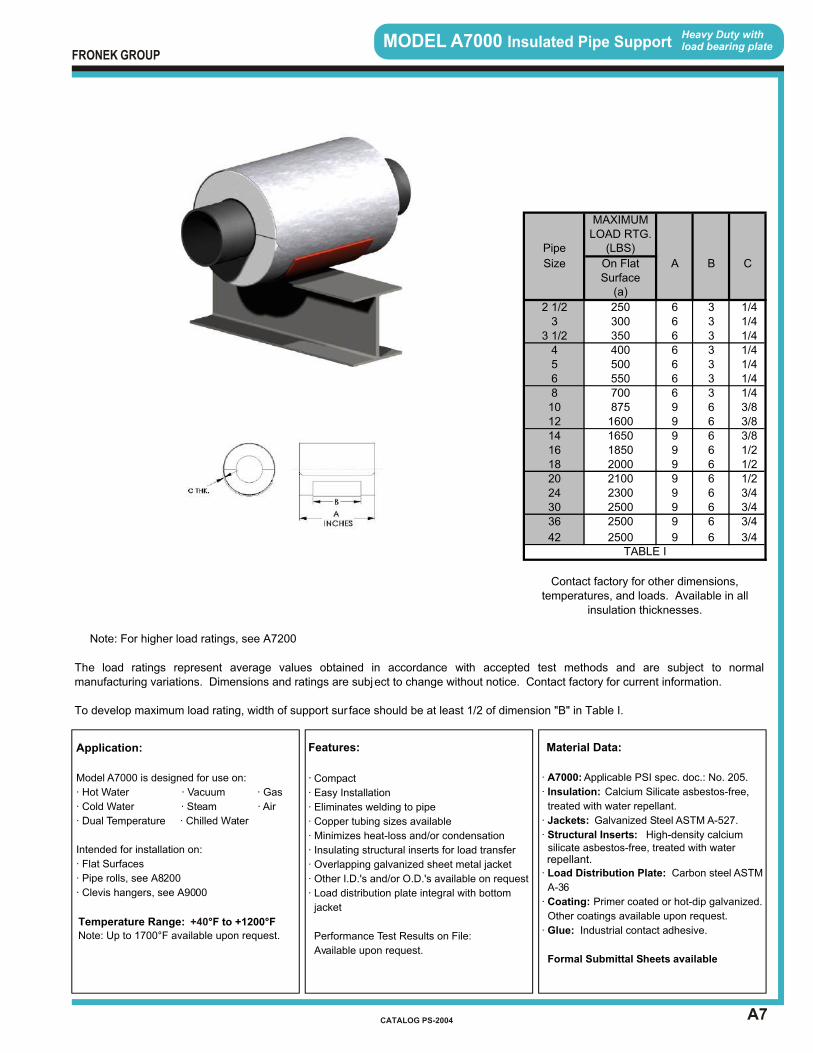
A7
MODEL A7000 Insulated Pipe Support Heavy Duty withload bearing plate
Features:
· Compact
· Easy Installation
· Eliminates welding to pipe
· Copper tubing sizes available
· Minimizes heat-loss and/or condensation
· Insulating structural inserts for load transfer
· Overlapping galvanized sheet metal jacket
· Other I.D.'s and/or O.D.'s available on request
· Load distribution plate integral with bottom
jacket
Performance Test Results on File:
Available upon request.
Material Data:
· A7000: Applicable PSI spec. doc.: No. 205.
· Insulation: Calcium Silicate asbestos-free,
treated with water repellant.
· Jackets: Galvanized Steel ASTM A-527.
· Structural Inserts: High-density calcium silicate asbestos-free, treated with water
· Load Distribution Plate: Carbon steel ASTM
A-36
· Coating: Primer coated or hot-dip galvanized.
Other coatings available upon request.
· Glue: Industrial contact adhesive.
Formal Submittal Sheets available
repellant.
Application:
Model A7000 is designed for use on:
· Hot Water · Vacuum · Gas
· Cold Water · Steam · Air
· Dual Temperature · Chilled Water
Intended for installation on:
· Flat Surfaces
· Pipe rolls, see A8200
· Clevis hangers, see A9000
Note: Up to 1700°F available upon request.
Temperature Range: °F to +1200°F +40
FRONEK GROUP
CATALOG PS-2004
A B C
6 3 1/46 3 1/46 3 1/46 3 1/46 3 1/46 3 1/46 3 1/49 6 3/89 6 3/89 6 3/89 6 1/29 6 1/29 6 1/29 6 3/49 6 3/49 6 3/4
9 6 3/4
Surface
350
Pipe (LBS)
(a)
3
TABLE I
MAXIMUMLOAD RTG.
2 1/2 250300
1850
8
3 1/2
2500
6
45
2000
400
101214 1650
500
16182024
25002500
3036
On FlatSize
The load ratings represent average values obtained in accordance with accepted test methods and are subject to normalmanufacturing variations. Dimensions and ratings are subject to change without notice. Contact factory for current information.
5507008751600
42
21002300
To develop maximum load rating, width of support sur face should be at least 1/2 of dimension "B" in Table I.
Contact factory for other dimensions, temperatures, and loads. Available in all
insulation thicknesses.
Note: For higher load ratings, see A7200

A8
MODEL A7200 Insulated Pipe Support Heavy Duty withload bearing plate
Features:
· Compact
· Easy Installation
· Eliminates welding to pipe
· Copper tubing sizes available
· Minimizes heat-loss and/or condensation
· Insulating structural inserts for load transfer
· Overlapping galvanized sheet metal jacket
· Other I.D.'s and/or O.D.'s available on
request
· Load distribution plate integral with bottom
jacket
Performance Test Results on File:
Available upon request
Material Data:
· A7200: Applicable PSI spec. doc.: No. 205.
· Insulation: Calcium Silicate asbestos-free,
treated with water repellant.
· Jackets: Galvanized Steel ASTM A-527.
· Structural Inserts: High-density calciumsilicate asbestos-free, treated with water
· Load distribution Plate: Carbon steel ASTM
A-36
· Coating: Primer coated or hot-dip galvanized.
Other coatings available upon request.
· Glue: Industrial contact adhesive.
Formal Submittal Sheets available
repellant.
Application:
Model A7200 is designed for use on:
· Hot Water · Vacuum · Gas
· Cold Water · Steam · Air
· Chilled Water
· Dual Temperature
Intended for installation on:
· Flat Surfaces
· Pipe rolls, see A8200
· Clevis hangers, see A9000
Note: Up to 1700°F available upon request.
Temperature Range: °F to +1200°F +40
FRONEK GROUP
CATALOG PS-2004
A B C
9 6 1/29 6 1/29 6 5/89 6 5/89 6 5/89 6 3/49 6 3/49 6 3/49 6 19 6 19 6 19 6 1
MAXIMUMLOAD RTG.
Pipe (LBS)
Size On FlatSurface
(a)
6 10008 125010 155012 225014 278016 330018 360020 380024 410030 4500
Contact factory for other dimensions, temperatures, and loads. Available in all
insulation thicknesses.
TABLE I
36 450042 4500
Note: For higher load ratings, see A7400, B1100
The load ratings represent average values obtained in accordance with accepted test methods and are subject to normalmanufacturing variations. Dimensions and ratings are subject to change without notice. Contact factory for current information.
To develop maximum load rating, width of support sur face should be at least 1/2 of dimension "B" in Table I.
A9
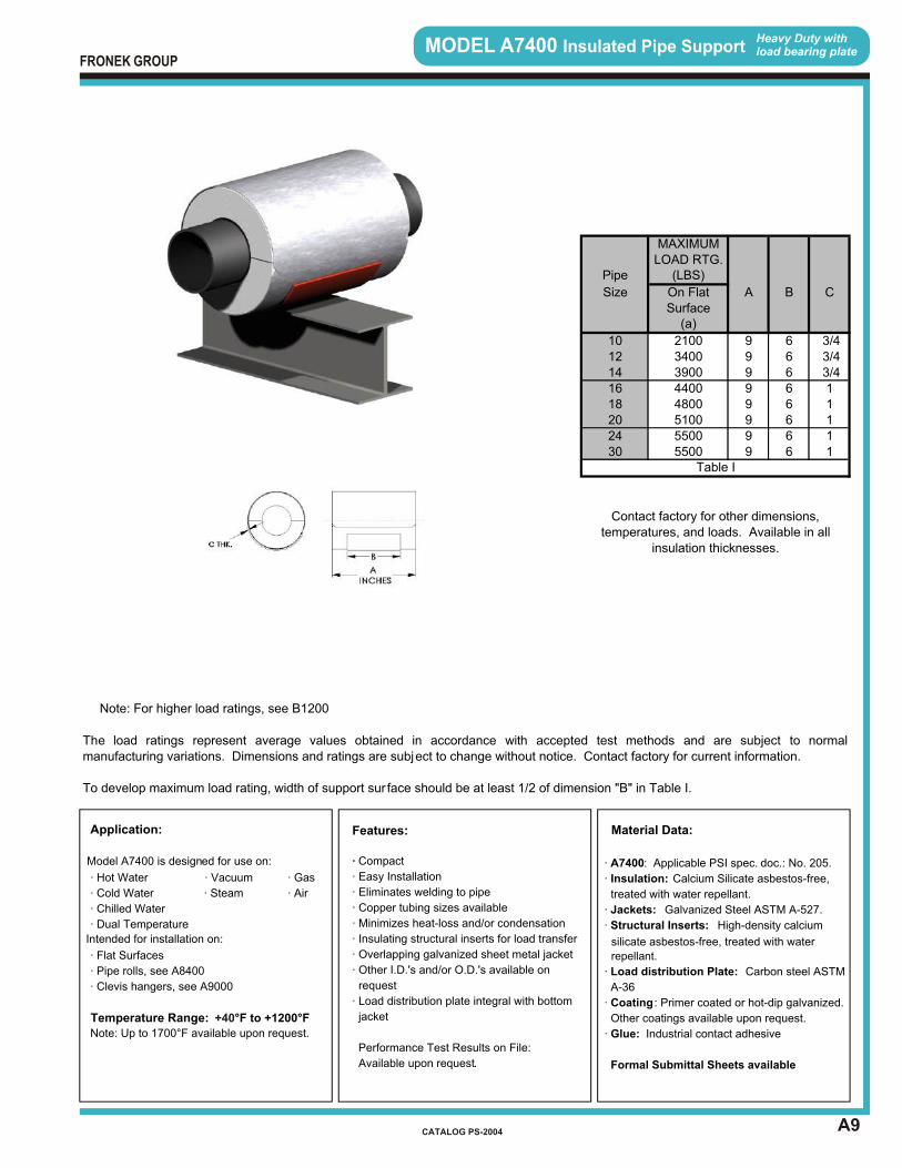
MODEL A7400 Insulated Pipe Support Heavy Duty withload bearing plate
·
Features:
Compact
· Easy Installation
· Eliminates welding to pipe
· Copper tubing sizes available
· Minimizes heat-loss and/or condensation
· Insulating structural inserts for load transfer
· Overlapping galvanized sheet metal jacket
· Other I.D.'s and/or O.D.'s available on
request
· Load distribution plate integral with bottom
jacket
Performance Test Results on File:
Available upon request.
Material Data:
· A7400: Applicable PSI spec. doc.: No. 205.
· Insulation: Calcium Silicate asbestos-free,
treated with water repellant.
· Jackets: Galvanized Steel ASTM A-527.
· Structural Inserts: High-density calcium
silicate asbestos-free, treated with water
· Load distribution Plate: Carbon steel ASTM
A-36
· Coating : Primer coated or hot-dip galvanized.
Other coatings available upon request.
· Glue: Industrial contact adhesive
Formal Submittal Sheets available
repellant.
Application:
Model A7400 is designed for use on:
· Hot Water · Vacuum · Gas
· Cold Water · Steam · Air
· Chilled Water
· Dual Temperature
Intended for installation on:
· Flat Surfaces
· Pipe rolls, see A8400
· Clevis hangers, see A9000
Note: Up to 1700°F available upon request.
Temperature Range: °F to +1200°F +40
FRONEK GROUP
CATALOG PS-2004
A B C
9 6 3/49 6 3/49 6 3/49 6 19 6 19 6 19 6 19 6 1
MAXIMUMLOAD RTG.
Pipe (LBS)
Size On FlatSurface
(a)
10 210012 340014 390016 440018 480020 510024 550030 5500
Table I
Contact factory for other dimensions, temperatures, and loads. Available in all
insulation thicknesses.
Note: For higher load ratings, see B1200
The load ratings represent average values obtained in accordance with accepted test methods and are subject to normalmanufacturing variations. Dimensions and ratings are subject to change without notice. Contact factory for current information.
To develop maximum load rating, width of support sur face should be at least 1/2 of dimension "B" in Table I.

A10
MODEL A8000 Insulated Pipe Support Heavy Duty withload bearing plate
Features:
· Compact
· Easy Installation
· Eliminates welding to pipe
· Copper tubing sizes available
· Minimizes heat-loss and/or condensation
· Insulating structural inserts for load transfer
· Overlapping galvanized sheet metal jacket
· Other I.D.'s and/or O.D.'s available on request
· Load distribution plate integral with bottom
jacket
Performance Test Results on File:
Available upon request.
Material Data:
· A8000: Applicable PSI spec. doc. No. 205.
· Insulation: Calcium Silicate asbestos-free,
treated with water repellant.
· Jackets: Galvanized Steel ASTM A-527.
· Structural Inserts: High-density calcium
silicate asbestos-free, treated with water
repellant.
· Load Distribution Plate: Carbon steel ASTM
A-36
· Coating: Primer coated or hot-dip galvanized.
Other coatings available upon request.
· Glue: Industrial contact adhesive.
Formal Submittal Sheets available
Application:
Model A8000 is designed for use on:
· Hot Water · Vacuum · Gas
· Cold Water · Steam · Air
· Chilled Water
· Dual Temperature
Intended for installation on:
· Flat Surfaces
· Pipe rolls, see A7000
· Clevis hangers, see A9000
Note: Up to 1700°F available upon request.
Temperature Range: °F to +1200°F +40
FRONEK GROUP
CATALOG PS-2004
A B C
9 6 1/49 6 1/49 6 1/49 6 1/49 6 1/49 6 1/49 6 1/412 9 3/812 9 3/812 9 3/812 9 1/212 9 1/212 9 1/212 9 3/412 9 3/412 9 3/412 9 3/4
Hardware sold separately
MAXIMUM Max. AxialLOAD RTG. Travel
Pipe (LBS) (Inches)
Size On onPipe Pipe RollRoll
2 1/2 225 23 250 2
3 1/2 300 24 350 25 450 26 500 28 625 210 875 412 1400 414 1475 416 1650 418 1800 420 1875 424 2050 4
436 2250 430 2250
4TABLE I
42 2250
Contact factory for other dimensions, temperatures , and loads. Available in all insulation thicknesses.
Note: For higher load ratings, see A8200
The load ratings represent average values obtained in accordance with accepted test methods and are subject to normalmanufacturing variations. Dimensions and ratings are subject to change without notice. Contact factory for current information.
A11
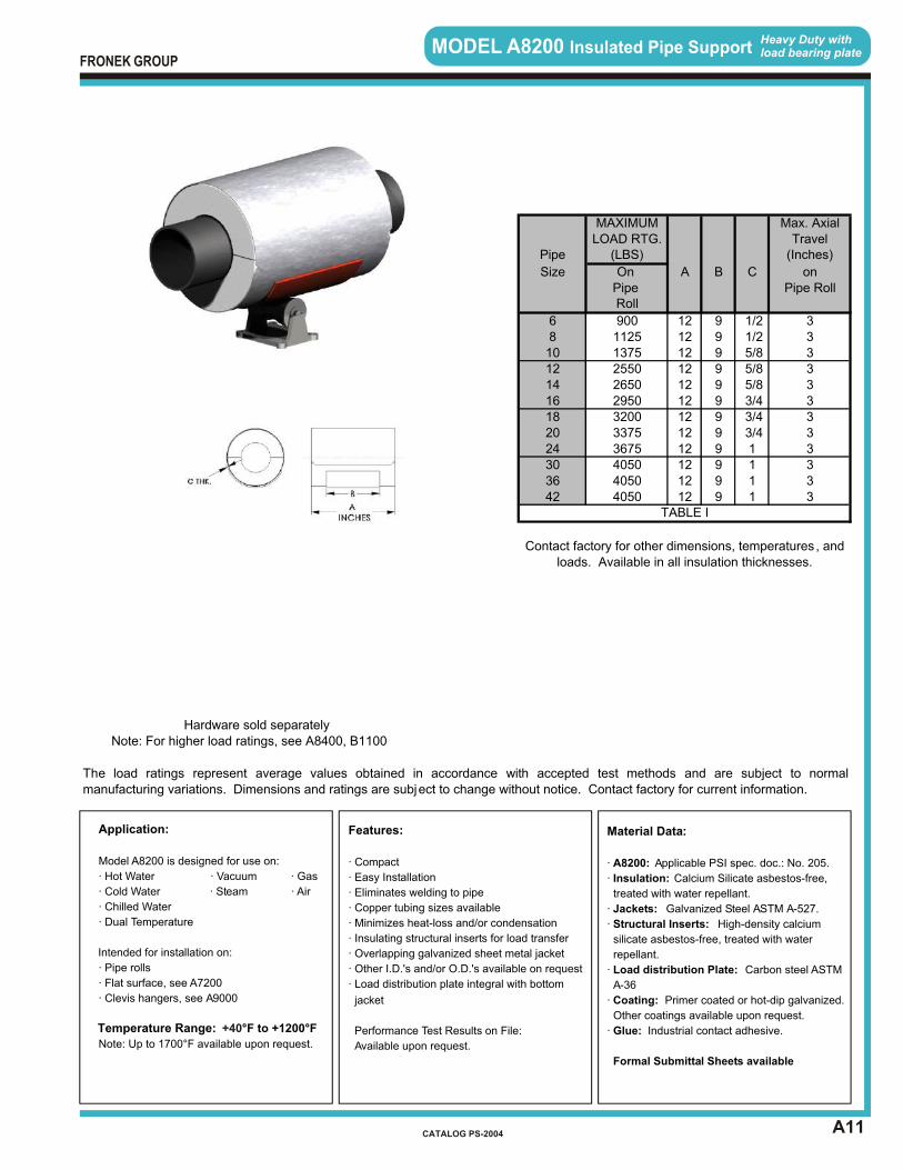
MODEL A8200 Insulated Pipe Support Heavy Duty withload bearing plate
Features:
· Compact
· Easy Installation
· Eliminates welding to pipe
· Copper tubing sizes available
· Minimizes heat-loss and/or condensation
· Insulating structural inserts for load transfer
· Overlapping galvanized sheet metal jacket
· Other I.D.'s and/or O.D.'s available on request
· Load distribution plate integral with bottom
jacket
Performance Test Results on File:
Available upon request.
Material Data:
· A8200: Applicable PSI spec. doc.: No. 205.
· Insulation: Calcium Silicate asbestos-free,
treated with water repellant.
· Jackets: Galvanized Steel ASTM A-527.
· Structural Inserts: High-density calcium
silicate asbestos-free, treated with water
repellant.
· Load distribution Plate: Carbon steel ASTM
A-36
· Coating: Primer coated or hot-dip galvanized.
Other coatings available upon request.
· Glue: Industrial contact adhesive.
Formal Submittal Sheets available
Application:
Model A8200 is designed for use on:
· Hot Water · Vacuum · Gas
· Cold Water · Steam · Air
· Chilled Water
· Dual Temperature
Intended for installation on:
· Pipe rolls
· Flat surface, see A7200
· Clevis hangers, see A9000
Note: Up to 1700°F available upon request.
Temperature Range: °F to +1200°F +40
FRONEK GROUP
CATALOG PS-2004
A B C
12 9 1/212 9 1/212 9 5/812 9 5/812 9 5/812 9 3/412 9 3/412 9 3/412 9 112 9 112 9 112 9 1
Hardware sold separatelyNote: For higher load ratings, see A8400, B1100
The load ratings represent average values obtained in accordance with accepted test methods and are subject to normalmanufacturing variations. Dimensions and ratings are subject to change without notice. Contact factory for current information.
TABLE I
Contact factory for other dimensions, temperatures , and loads. Available in all insulation thicknesses.
36 4050 342 4050 3
24 3675 330 4050 3
18 3200 320 3375 3
14 2650 316 2950 3
10 1375 312 2550 3
6 900 38 1125 3
Pipe Pipe RollRoll
Pipe (LBS) (Inches)
Size On on
MAXIMUM Max. AxialLOAD RTG. Travel
A12
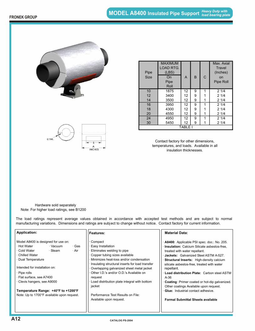
MODEL A8400 Insulated Pipe Support Heavy Duty withload bearing plate
Features:
· Compact
· Easy Installation
· Eliminates welding to pipe
· Copper tubing sizes available
· Minimizes heat-loss and/or condensation
· Insulating structural inserts for load transfer
· Overlapping galvanized sheet metal jacket
· Other I.D.'s and/or O.D.'s Available on
request
· Load distribution plate integral with bottom
jacket
Performance Test Results on File:
Available upon request.
Material Data:
· A8400: Applicable PSI spec. doc.: No. 205.
· Insulation: Calcium Silicate asbestos-free,
treated with water repellant.
· Jackets: Galvanized Steel ASTM A-527.
· Structural Inserts: High-density calcium
silicate asbestos-free, treated with water
· Load distribution Plate: Carbon steel ASTM
A-36
· Coating : Primer coated or hot-dip galvanized.
Other coatings Available upon request.
· Glue: Industrial contact adhesive.
Formal Submittal Sheets available
repellant.
Application:
Model A8400 is designed for use on:
· Hot Water · Vacuum · Gas
· Cold Water · Steam · Air
· Chilled Water
· Dual Temperature
Intended for installation on:
· Pipe rolls
· Flat surface, see A7400
· Clevis hangers, see A9000
Note: Up to 1700°F available upon request.
Temperature Range: °F to +1200°F +40
FRONEK GROUP
CATALOG PS-2004
A B C
12 9 112 9 112 9 112 9 112 9 112 9 112 9 112 9 1
Hardware sold separately
MAXIMUM Max. AxialLOAD RTG. Travel
Pipe (LBS) (Inches)
Size On onPipe Pipe RollRoll
10 1875 2 1/412 3400 2 1/414 3500 2 1/416 3950 2 1/418 4300 2 1/420 4550 2 1/424 4950 2 1/430 5450 2 1/4
TABLE I
Contact factory for other dimensions, temperatures, and loads. Available in all
insulation thicknesses.
Note: For higher load ratings, see B1200
The load ratings represent average values obtained in accordance with accepted test methods and are subject to normalmanufacturing variations. Dimensions and ratings are subject to change without notice. Contact factory for current information.
A13
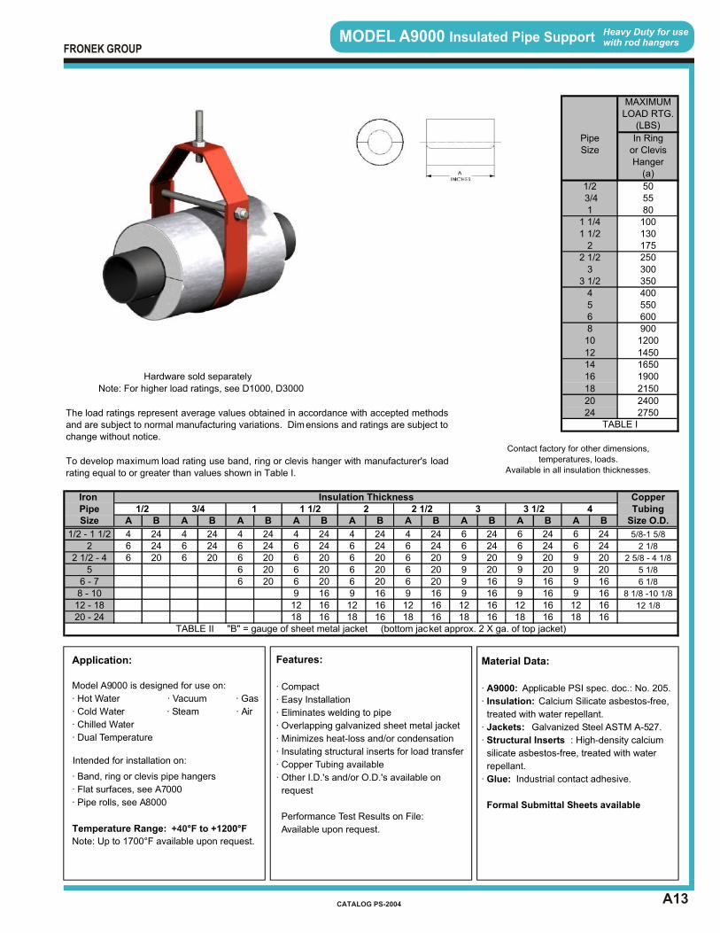
MODEL A9000 Insulated Pipe Support Heavy Duty for usewith rod hangers
Features:
· Compact
· Easy Installation
· Eliminates welding to pipe
· Overlapping galvanized sheet metal jacket
· Minimizes heat-loss and/or condensation
· Insulating structural inserts for load transfer
· Copper Tubing available
· Other I.D.'s and/or O.D.'s available on
request
Performance Test Results on File:
Available upon request.
Material Data:
· A9000: Applicable PSI spec. doc.: No. 205.
· Insulation: Calcium Silicate asbestos-free,
treated with water repellant.
· Jackets: Galvanized Steel ASTM A-527.
· Structural Inserts : High-density calcium
silicate asbestos-free, treated with water
repellant.
· Glue: Industrial contact adhesive.
Formal Submittal Sheets available
Application:
Model A9000 is designed for use on:
· Hot Water · Vacuum · Gas
· Cold Water · Steam · Air
· Chilled Water
· Dual Temperature
Intended for installation on:
· Band, ring or clevis pipe hangers
· Flat surfaces, see A7000
· Pipe rolls, see A8000
Note: Up to 1700°F available upon request.
Temperature Range: °F to +1200°F +40
FRONEK GROUP
CATALOG PS-2004
Hardware sold separately
A B A B A B A B A B A B A B A B A B
4 24 4 24 4 24 4 24 4 24 4 24 6 24 6 24 6 246 24 6 24 6 24 6 24 6 24 6 24 6 24 6 24 6 246 20 6 20 6 20 6 20 6 20 6 20 9 20 9 20 9 20
6 20 6 20 6 20 6 20 9 20 9 20 9 206 20 6 20 6 20 6 20 9 16 9 16 9 16
9 16 9 16 9 16 9 16 9 16 9 1612 16 12 16 12 16 12 16 12 16 12 1618 16 18 16 18 16 18 16 18 16 18 1620 - 24
TABLE II "B" = gauge of sheet metal jacket (bottom jacket approx. 2 X ga. of top jacket)
8 - 10 8 1/8 -10 1/8
12 - 18 12 1/8
5 5 1/8
6 - 7 6 1/8
5/8-1 5/8
2 2 1/8
2 1/2 - 4 2 5/8 - 4 1/8
1/2 3/4 1
1/2 - 1 1/2
3 1/2 4 TubingSize Size O.D.
1 1/2 2 2 1/2 3Pipe
TABLE I
Iron Insulation Thickness Copper
Contact factory for other dimensions, temperatures, loads.
Available in all insulation thicknesses.To develop maximum load rating use band, ring or clevis hanger with manufacturer's loadrating equal to or greater than values shown in Table I.
20 240024 2750
Note: For higher load ratings, see D1000, D3000
The load ratings represent average values obtained in accordance with accepted methodsand are subject to normal manufacturing variations. Dimensions and ratings are subject to change without notice.
6 6008 900
16
18
1200
1450
4 4005 550
3 3003 1/2 350
2 1752 1/2 250
1 1/4 1001 1/2 130
1/2 505580
3/41
or ClevisHanger
(a)
Size
MAXIMUM
(LBS)
In RingPipe
LOAD RTG.
16501900
2150
10
1214
FRONEK GROUP
INTRODUCTION SECTION “B”
INTRODUCTION
SECTION “B”
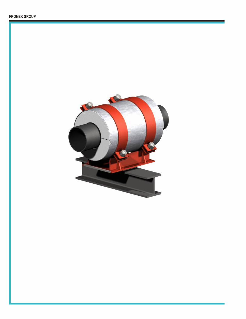
PRE-INSULATED PIPE SUPPORTS - Base Mounted APPLICATION – Heavy Industrial and Large HVAC Distribution Systems Features:
· Accommodation of thermal movement · Provision or lateral guide or restraint · Minimization of side friction loads · Wide range of maximum load requirements for each pipe size
In each model number series (for example: B1000 through B1300 Series), the higher the model number, the higher the load rating. Models B1000 - B1300 Sliding supports free to travel axially and laterally. Models B2000 - B2300 Same as B1000 - B1300 except can accommodate greater axial travel. Models B3000 - B3300 Sliding supports with lateral guides. Models B4000 - B4300 Same as B3000 - B3300 except can accommodate greater axial travel. Models B5000 - B5300 Same as B1000 - B1300 except can accommodate greater lateral travel. Models B6000 - B6300 Same as B2000 - B2300 except can accommodate greater lateral travel. Models B7000 - B7300 Same as B3000 - B3300 except with reduced vertical load ratings to
allow greater lateral loads. Minimum side friction is assured by the addition of lateral slide pads.
Models B8000 - B8300 Same as B4000 - B4300 except with reduced vertical load ratings to
allow greater lateral loads. Minimum side friction is assured by the addition of lateral slide pads.
To meet special thermal movement requirements, Pipe Shields Inc. has provided supports that have accommodated axial travels in excess of five (5) feet. By modifying our standard pipe support concept with combinations of structural insulation materials, steel base and strap design, and slide plate configuration, we can readily and economically respond to virtually any pipe support requirement.
If your requirements are not covered by the Product Data Sheets in this catalog, please contact us at 713-731-0030 or 1-800-787-5914.
Please acquaint yourself with the selection guide at the front of this catalog and the section index on the page following this introduction, for assistance in determining the most
appropriate support for your application.
FRONEK GROUP
CATALOG PS-2004
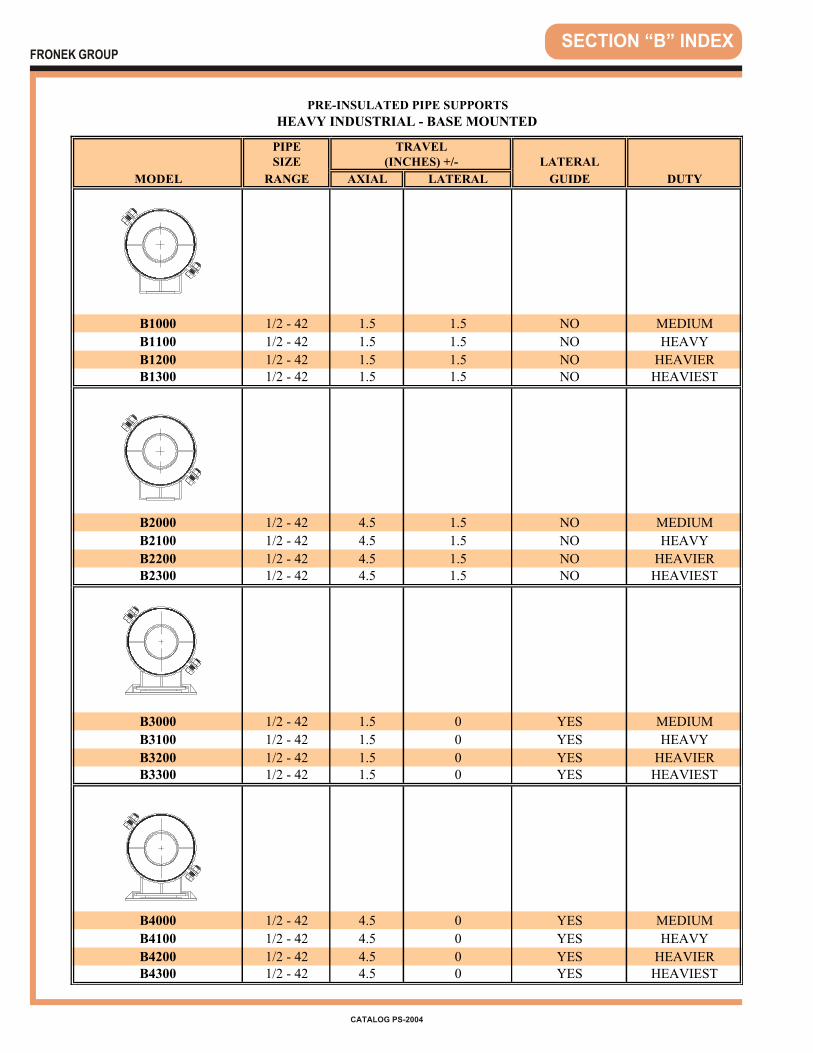
PIPESIZE LATERAL
MODEL RANGE AXIAL LATERAL GUIDE DUTY
B1000 1/2 - 42 1.5 1.5 NO MEDIUM
B1100 1/2 - 42 1.5 1.5 NO HEAVY
B1200 1/2 - 42 1.5 1.5 NO HEAVIERB1300 1/2 - 42 1.5 1.5 NO HEAVIEST
B2000 1/2 - 42 4.5 1.5 NO MEDIUM
B2100 1/2 - 42 4.5 1.5 NO HEAVY
B2200 1/2 - 42 4.5 1.5 NO HEAVIERB2300 1/2 - 42 4.5 1.5 NO HEAVIEST
B3000 1/2 - 42 1.5 0 YES MEDIUM
B3100 1/2 - 42 1.5 0 YES HEAVY
B3200 1/2 - 42 1.5 0 YES HEAVIERB3300 1/2 - 42 1.5 0 YES HEAVIEST
B4000 1/2 - 42 4.5 0 YES MEDIUM
B4100 1/2 - 42 4.5 0 YES HEAVY
B4200 1/2 - 42 4.5 0 YES HEAVIERB4300 1/2 - 42 4.5 0 YES HEAVIEST
PRE-INSULATED PIPE SUPPORTS
HEAVY INDUSTRIAL - BASE MOUNTED
TRAVEL(INCHES) +/-
SECTION “B” INDEXFRONEK GROUP
CATALOG PS-2004
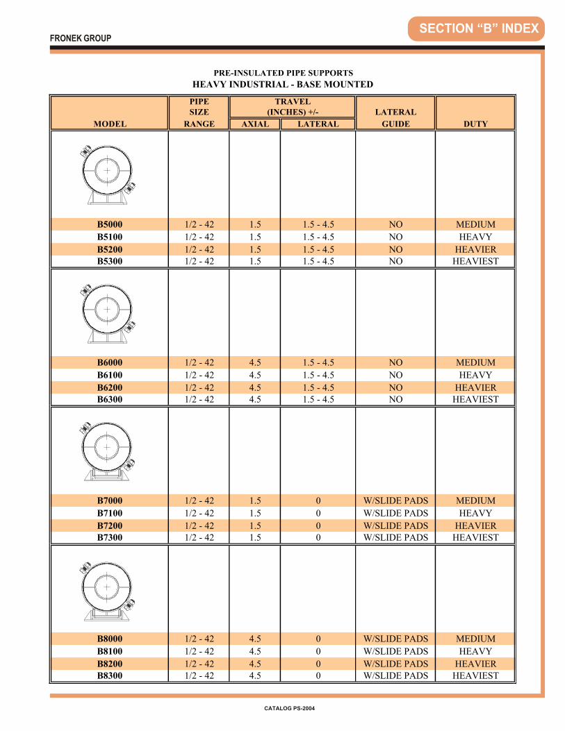
PIPESIZE LATERAL
MODEL RANGE AXIAL LATERAL GUIDE DUTY
B5000 1/2 - 42 1.5 1.5 - 4.5 NO MEDIUM
B5100 1/2 - 42 1.5 1.5 - 4.5 NO HEAVY
B5200 1/2 - 42 1.5 1.5 - 4.5 NO HEAVIERB5300 1/2 - 42 1.5 1.5 - 4.5 NO HEAVIEST
B6000 1/2 - 42 4.5 1.5 - 4.5 NO MEDIUM
B6100 1/2 - 42 4.5 1.5 - 4.5 NO HEAVY
B6200 1/2 - 42 4.5 1.5 - 4.5 NO HEAVIERB6300 1/2 - 42 4.5 1.5 - 4.5 NO HEAVIEST
B7000 1/2 - 42 1.5 0 W/SLIDE PADS MEDIUM
B7100 1/2 - 42 1.5 0 W/SLIDE PADS HEAVY
B7200 1/2 - 42 1.5 0 W/SLIDE PADS HEAVIERB7300 1/2 - 42 1.5 0 W/SLIDE PADS HEAVIEST
B8000 1/2 - 42 4.5 0 W/SLIDE PADS MEDIUM
B8100 1/2 - 42 4.5 0 W/SLIDE PADS HEAVY
B8200 1/2 - 42 4.5 0 W/SLIDE PADS HEAVIERB8300 1/2 - 42 4.5 0 W/SLIDE PADS HEAVIEST
PRE-INSULATED PIPE SUPPORTS
HEAVY INDUSTRIAL - BASE MOUNTED
TRAVEL(INCHES) +/-
SECTION “B” INDEXFRONEK GROUP
CATALOG PS-2004

SECTION “B” INDEX
TO ORDER, specify:1. Quantity 202. Pipe Size & Type 18” IPS3. Insulation Thickness 2”4. Model Number B1000
EXAMPLE: (20) 18 x 2 B1000
FRONEK GROUP
CATALOG PS-2004
PIPE
SIZE 3 1/2 4 1/2 5 1/2 6 1/2
3 6 6 8 83 1/2 6 6 8 8
4 6 6 8 85 6 6 8 86 6 6 8 88 6 8 8 1010 6 8 8 1012 6 8 8 1014 6 8 8 1016 6 8 8 1018 6 8 8 1020 6 8 8 1024 6 8 8 1030 8 8 10 1036 8 8 10 1042 8 8 10 10
The Table above provides Bottom-of-Pipe to Top-of Steel dimensions ("B" dimensions) for3 1/2", 4 1/2", 5 1/2" and 6 1/2 " insulation thicknesses. Check with your salesperson if yourequire a "B" dimension other than those shown in this table.
INSULATION THICKNESS
THE FOLLOWING TABLE ILLUSTRATESBOTTOM-OF-PIPE TO TOP-OF STEEL DIMENSIONS
(DIMENSION "B") FOR "B" MODEL PIPE SUPPORTS AND "C" MODEL PIPE ANCHORSFOR INTERMEDIATE INSULATION THICKNESS
B1
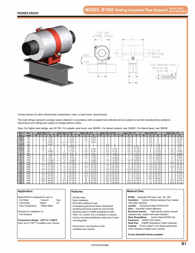
Application:
Model B1000 is designed for use on:
· Hot Water · Vacuum · Gas
· Cold Water · Steam · Air
· Dual Temperature · Chilled Water
Intended for installation on:
· Flat Surfaces
Temperature Range: +40°F to +1200°F
Note: Up to 1700° F available upon request.
Features:
· All pipe sizes
· Easy Installation
· Eliminates welding to pipe
· Overlapping galvanized sheet metal jacket
· Insulating structural inserts for load transfer
· Stainless steel to UHMW polyethylene slide
· Other I.D.'s and/or O.D.'s available on request
· Factory mounted polyethylene slide pad on steel
mounting plate
Performance Test Results on File:
Available upon request.
Material Data:
· B1000: Applicable PSI spec. doc.: No. 209.
· Insulation: Calcium Silicate asbestos-free, treated
with water repellant.
· Jackets: Galvanized Steel ASTM A-527.
· Glue: Industrial contact adhesive
· Structural Inserts: High-density calcium silicate
asbestos free, treated with water repellant.
· Steel Straps/Base: Carbon Steel ASTM A-36.
· Fasteners: ASTM A-307 plated.
· Slide Pad: UHMW Polythylene (Teflon Optional).
· Coating: Primer coated or hot dipped galvanized.
Other coatings available upon request.
Formal Submittal Sheets available.
Heavy Duty,Base Mounted MODEL B1000 Sliding Insulated Pipe Support
FRONEK GROUP
CATALOG PS-2004
The load ratings represent average values obtained in accordance with accepted test methods and are subject to normal manufacturing variations.
Dimensions and ratings are subject to change without notice.
Note: For higher load ratings, see: B1100 - For greater axial travel, see: B2000 - For lateral restraint, see: B3000 - For lateral travel, see: B5000
Pipe Vert.Size Load B C E B C E B C E B C E B C E B C E B C E
1/2 140 4 1.5 3.25 4 2 4.375 4 2.5 5.375 4 4 7 6 4.5 8 6 6.5 10 8 8 12.125 3/4 175 4 1.5 3.25 4 2 4.375 4 2.5 5.375 4 4 7 6 4.5 8 6 6.5 10 8 8 12.1251 225 4 2 3.875 4 2.5 4.875 4 3 5.937 4 4 7 6 4.5 8 6 6.5 10 8 8 12.25
1 1/2 325 4 2 4.375 4 2.5 5.5 4 4 7 4 4.5 8 6 5.5 9 6 7.5 11.25 8 9 13.252 375 4 2.5 5 4 3 6.0625 4 4 7 4 4.5 8 6 5.5 9.125 6 7.5 11.25 8 9 13.25
2 1/2 460 4 2.5 5.5 4 4 7.125 4 4.5 8.125 4 5.5 9.125 6 6.5 10.125 6 8 12.25 8 9.5 14.53 530 4 3 6.062 4 4 7.125 4 4.5 8.125 4 5.5 9.125 6 6.5 10.125 6 8 12.375 8 9.5 14.6254 840 4 4 7.25 4 4.5 8.25 4 5.5 9.25 4 6.5 10.25 6 7.5 11.375 6 9 13.375 8 10.5 15.6255 1050 4 4.5 8.25 4 5.5 9.25 4 6.5 10.25 4 7.5 11.375 6 8 12.375 6 9.5 14.875 8 11 16.8756 1275 4 5.5 9.25 4 6.5 10.25 4 7.5 11.375 4 8 12.625 6 9 13.625 6 10.5 15.875 8 12 17.8758 1700 4 7.5 11.625 4 8 12.625 4 9 13.625 6 9.5 14.875 6 10.5 15.875 6 12 17.875 8 13 20.12510 2000 4 9 13.625 4 9.5 14.875 4 10.5 15.875 6 11 16.875 6 12 18.125 6 13 20.125 8 14.5 22.12512 2200 4 10.5 16.125 4 11 17.125 4 12 18.125 6 12.5 19.125 6 13 20.125 6 14.5 22.125 8 16 24.12514 2500 4 11 17.125 4 12 18.125 4 12.5 19.125 6 13 20.125 6 14 21.125 6 15.5 23.125 8 16.5 25.12516 2900 4 12.5 19.125 4 13 20.125 6 14 21.375 6 14.5 22.375 6 15.5 23.375 8 16.5 25.375 8 18 27.37518 3200 4 14 21.375 4 14.5 22.375 6 15.5 23.375 6 16 24.375 6 16.5 25.375 8 18 27.375 8 19.5 29.37520 3400 4 15.5 23.375 4 16 24.375 6 16.5 25.375 6 17.5 26.375 6 18 27.375 8 19.5 29.375 8 21 31.37524 3600 4 18 27.375 4 19 28.375 6 19.5 29.375 6 20.5 30.375 6 21 31.375 8 22.5 33.375 8 24 35.37530 4700 4 22.5 33.625 6 23 34.625 6 24 35.625 6 24.5 36.625 6 25 37.625 8 26.5 39.625 8 28 41.62536 5500 4 26.5 39.625 6 27.5 41.125 6 28 42.125 6 28.5 43.125 6 29.5 44.125 8 31 46.125 8 32.5 48.12542 6200 4 31 46.125 6 31.5 47.125 6 32.5 48.125 6 33 49.125 6 33.5 50.125 8 35 52.125 8 36.5 54.125
Contact factory for other dimensional, temperature, load, or axial travel, requirements.
Insul. Thk. = 3" Insul. Thk. =4" Insul. Thk. = 5"Insul. Thk. = 1" Insul. Thk. = 1-1/2" Insul. Thk. = 2" Insul. Thk. = 2-1/2"
B2
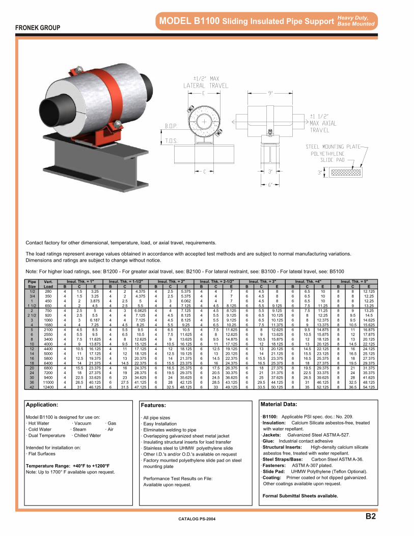
Heavy Duty,Base Mounted MODEL B1100 Sliding Insulated Pipe Support
Application:
Model B1100 is designed for use on:
· Hot Water · Vacuum · Gas
· Cold Water · Steam · Air
· Dual Temperature · Chilled Water
Intended for installation on:
· Flat Surfaces
Temperature Range: +40°F to +1200°F
Note: Up to 1700° F available upon request.
Features:
· All pipe sizes
· Easy Installation
· Eliminates welding to pipe
· Overlapping galvanized sheet metal jacket
· Insulating structural inserts for load transfer
· Stainless steel to UHMW polyethylene slide
· Other I.D.'s and/or O.D.'s available on request
· Factory mounted polyethylene slide pad on steel
mounting plate
Performance Test Results on File:
Available upon request.
Material Data:
· B1100: Applicable PSI spec. doc.: No. 209.
· Insulation: Calcium Silicate asbestos-free, treated
with water repellant.
· Jackets: Galvanized Steel ASTM A-527.
· Glue: Industrial contact adhesive
· Structural Inserts: High-density calcium silicate
asbestos free, treated with water repellant.
· Steel Straps/Base: Carbon Steel ASTM A-36.
· Fasteners: ASTM A-307 plated.
· Slide Pad: UHMW Polythylene (Teflon Optional).
· Coating: Primer coated or hot dipped galvanized.
Other coatings available upon request.
Formal Submittal Sheets available.
FRONEK GROUP
CATALOG PS-2004
The load ratings represent average values obtained in accordance with accepted test methods and are subject to normal manufacturing variations.
Dimensions and ratings are subject to change without notice.
Note: For higher load ratings, see: B1200 - For greater axial travel, see: B2100 - For lateral restraint, see: B3100 - For lateral travel, see: B5100
Pipe Vert.Size Load B C E B C E B C E B C E B C E B C E B C E
1/2 280 4 1.5 3.25 4 2 4.375 4 2.5 5.375 4 4 7 6 4.5 8 6 6.5 10 8 8 12.125 3/4 350 4 1.5 3.25 4 2 4.375 4 2.5 5.375 4 4 7 6 4.5 8 6 6.5 10 8 8 12.251 450 4 2 3.875 4 2.5 5 4 3 6.062 4 4 7 6 4.5 8 6 6.5 10 8 8 12.25
1 1/2 650 4 2 4.5 4 2.5 5.5 4 4 7.125 4 4.5 8.125 6 5.5 9.125 6 7.5 11.25 8 9 13.252 750 4 2.5 5 4 3 6.0625 4 4 7.125 4 4.5 8.125 6 5.5 9.125 6 7.5 11.25 8 9 13.25
2 1/2 920 4 2.5 5.5 4 4 7.125 4 4.5 8.125 4 5.5 9.125 6 6.5 10.125 6 8 12.25 8 9.5 14.53 1060 4 3 6.187 4 4 7.125 4 4.5 8.125 4 5.5 9.125 6 6.5 10.125 6 8 12.375 8 9.5 14.6254 1680 4 4 7.25 4 4.5 8.25 4 5.5 9.25 4 6.5 10.25 6 7.5 11.375 6 9 13.375 8 10.5 15.6255 2100 4 4.5 8.5 4 5.5 9.5 4 6.5 10.5 4 7.5 11.625 6 8 12.625 6 9.5 14.875 8 11 16.8756 2550 4 5.5 9.5 4 6.5 10.5 4 7.5 11.625 4 8 12.625 6 9 13.625 6 10.5 15.875 8 12 17.8758 3400 4 7.5 11.625 4 8 12.625 4 9 13.625 6 9.5 14.875 6 10.5 15.875 6 12 18.125 8 13 20.12510 4000 4 9 13.875 4 9.5 15.125 4 10.5 16.125 6 11 17.125 6 12 18.125 6 13 20.125 8 14.5 22.12512 4400 4 10.5 16.125 4 11 17.125 4 12 18.125 6 12.5 19.125 6 13 20.125 6 14.5 22.125 8 16 24.12514 5000 4 11 17.125 4 12 18.125 4 12.5 19.125 6 13 20.125 6 14 21.125 6 15.5 23.125 8 16.5 25.12516 5800 4 12.5 19.375 4 13 20.375 6 14 21.375 6 14.5 22.375 6 15.5 23.375 8 16.5 25.375 8 18 27.37518 6400 4 14 21.375 4 14.5 22.375 6 15.5 23.375 6 16 24.375 6 16.5 25.375 8 18 27.375 8 19.5 29.37520 6800 4 15.5 23.375 4 16 24.375 6 16.5 25.375 6 17.5 26.375 6 18 27.375 8 19.5 29.375 8 21 31.37524 7200 4 18 27.375 4 19 28.375 6 19.5 29.375 6 20.5 30.375 6 21 31.375 8 22.5 33.375 8 24 35.37530 9400 4 22.5 33.625 6 23 34.625 6 24 35.625 6 24.5 36.625 6 25 37.625 8 26.5 39.625 8 28 41.62536 11000 4 26.5 40.125 6 27.5 41.125 6 28 42.125 6 28.5 43.125 6 29.5 44.125 8 31 46.125 8 32.5 48.12542 12400 4 31 46.125 6 31.5 47.125 6 32.5 48.125 6 33 49.125 6 33.5 50.125 8 35 52.125 8 36.5 54.125
Contact factory for other dimensional, temperature, load, or axial travel, requirements.
Insul. Thk. = 3" Insul. Thk. =4" Insul. Thk. = 5"Insul. Thk. = 1" Insul. Thk. = 1-1/2" Insul. Thk. = 2" Insul. Thk. = 2-1/2"

B3
Heavy Duty,Base Mounted MODEL B1200 Sliding Insulated Pipe Support
Application:
Model B1200 is designed for use on:
· Hot Water · Vacuum · Gas
· Cold Water · Steam · Air
· Dual Temperature · Chilled Water
Intended for installation on:
· Flat Surfaces
Temperature Range: +40°F to +1200°F
Note: Up to 1700° F available upon request.
Features:
· All pipe sizes
· Easy Installation
· Eliminates welding to pipe
· Overlapping galvanized sheet metal jacket
· Insulating structural inserts for load transfer
· Stainless steel to UHMW polyethylene slide
· Other I.D.'s and/or O.D.'s available on request
· Factory mounted polyethylene slide pad on steel
mounting plate
Performance Test Results on File:
Available upon request.
Material Data:
· B1200: Applicable PSI spec. doc.: No. 209.
· Insulation: Calcium Silicate asbestos-free, treated
with water repellant.
· Jackets: Galvanized Steel ASTM A-527.
· Glue: Industrial contact adhesive
· Structural Inserts: High-density calcium silicate
asbestos free, treated with water repellant.
· Steel Straps/Base: Carbon Steel ASTM A-36.
· Fasteners: ASTM A-307 plated.
· Slide Pad: UHMW Polyethylene (Teflon Optional).
· Coating: Primer coated or hot dipped galvanized.
Other coatings available upon request.
Formal Submittal Sheets available.
FRONEK GROUP
CATALOG PS-2004
Contact factory for other dimensional, temperature, load, or axial travel, requirements.
The load ratings represent average values obtained in accordance with accepted test methods and are subject to normal manufacturing variations.
Dimensions and ratings are subject to change without notice.
Note: For higher load ratings, see: B1300 - For greater axial travel, see: B2200 - For lateral restraint, see: B3200 - For lateral travel, see: B5200
Pipe Vert.Size Load B C E B C E B C E B C E B C E B C E B C E
1/2 400 4 1.5 3.25 4 2 4.375 4 2.5 5.375 4 4 7 6 4.5 8 6 6.5 10 8 8 12.125 3/4 500 4 1.5 3.25 4 2 4.375 4 2.5 5.375 4 4 7 6 4.5 8 6 6.5 10 8 8 12.251 650 4 2 4 4 2.5 5 4 3 6.062 4 4 7.125 6 4.5 8.125 6 6.5 10.125 8 8 12.25
1 1/2 950 4 2 4.5 4 2.5 5.5 4 4 7.125 4 4.5 8.125 6 5.5 9.125 6 7.5 11.25 8 9 13.252 1100 4 2.5 5 4 3 6.1875 4 4 7.125 4 4.5 8.125 6 5.5 9.125 6 7.5 11.25 8 9 13.25
2 1/2 1350 4 2.5 5.5 4 4 7.125 4 4.5 8.125 4 5.5 9.125 6 6.5 10.125 6 8 12.25 8 9.5 14.53 1600 4 3 6.187 4 4 7.125 4 4.5 8.125 4 5.5 9.125 6 6.5 10.125 6 8 12.375 8 9.5 14.6254 2500 4 4 7.25 4 4.5 8.25 4 5.5 9.25 4 6.5 10.25 6 7.5 11.375 6 9 13.375 8 10.5 15.6255 3100 4 4.5 8.5 4 5.5 9.5 4 6.5 10.5 4 7.5 11.625 6 8 12.625 6 9.5 14.875 8 11 16.8756 3800 4 5.5 9.5 4 6.5 10.5 4 7.5 11.625 4 8 12.625 6 9 13.625 6 10.5 15.875 8 12 17.8758 5100 4 7.5 11.625 4 8 12.625 4 9 13.625 6 9.5 14.875 6 10.5 15.875 6 12 18.125 8 13 20.12510 6000 4 9 13.875 4 9.5 15.125 4 10.5 16.125 6 11 17.125 6 12 18.125 6 13 20.125 8 14.5 22.12512 6600 4 10.5 16.125 4 11 17.125 4 12 18.125 6 12.5 19.125 6 13 20.125 6 14.5 22.125 8 16 24.12514 7500 4 11 17.125 4 12 18.125 4 12.5 19.125 6 13 20.125 6 14 21.125 6 15.5 23.125 8 16.5 25.12516 8700 4 12.5 19.375 4 13 20.375 6 14 21.375 6 14.5 22.375 6 15.5 23.375 8 16.5 25.375 8 18 27.37518 9600 4 14 21.375 4 14.5 22.375 6 15.5 23.375 6 16 24.375 6 16.5 25.375 8 18 27.375 8 19.5 29.37520 10200 4 15.5 23.375 4 16 24.375 6 16.5 25.375 6 17.5 26.375 6 18 27.375 8 19.5 29.375 8 21 31.37524 10800 4 18 27.375 4 19 28.375 6 19.5 29.375 6 20.5 30.375 6 21 31.375 8 22.5 33.375 8 24 35.37530 14100 4 22.5 33.625 6 23 34.625 6 24 35.625 6 24.5 36.625 6 25 37.625 8 26.5 39.625 8 28 41.62536 16500 4 26.5 40.125 6 27.5 41.125 6 28 42.125 6 28.5 43.125 6 29.5 44.125 8 31 46.125 8 32.5 48.12542 18600 4 31 46.125 6 31.5 47.125 6 32.5 48.125 6 33 49.125 6 33.5 50.125 8 35 52.125 8 36.5 54.125
Insul. Thk. = 3" Insul. Thk. =4" Insul. Thk. = 5"Insul. Thk. = 1" Insul. Thk. = 1-1/2" Insul. Thk. = 2" Insul. Thk. = 2-1/2"
B4
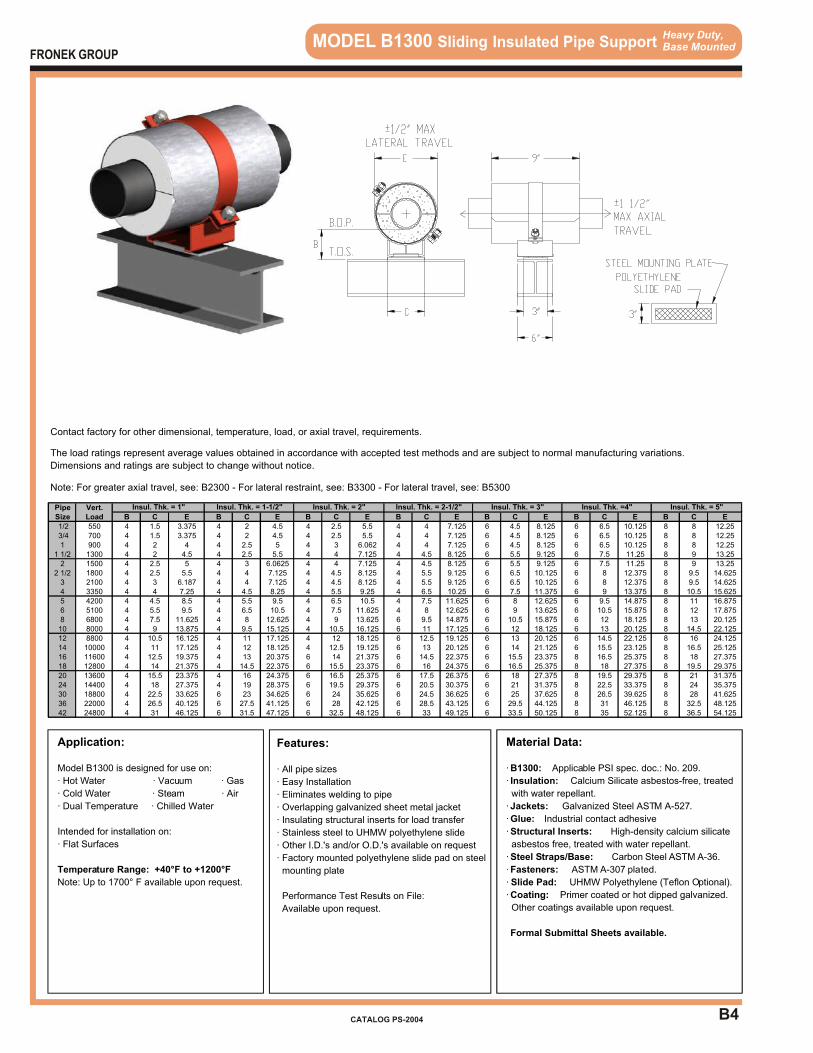
Heavy Duty,Base Mounted MODEL B1300 Sliding Insulated Pipe Support
Application:
Model B1300 is designed for use on:
· Hot Water · Vacuum · Gas
· Cold Water · Steam · Air
· Dual Temperature · Chilled Water
Intended for installation on:
· Flat Surfaces
Temperature Range: +40°F to +1200°F
Note: Up to 1700° F available upon request.
Features:
· All pipe sizes
· Easy Installation
· Eliminates welding to pipe
· Overlapping galvanized sheet metal jacket
· Insulating structural inserts for load transfer
· Stainless steel to UHMW polyethylene slide
· Other I.D.'s and/or O.D.'s available on request
· Factory mounted polyethylene slide pad on steel
mounting plate
Performance Test Results on File:
Available upon request.
Material Data:
· B1300: Applicable PSI spec. doc.: No. 209.
· Insulation: Calcium Silicate asbestos-free, treated
with water repellant.
· Jackets: Galvanized Steel ASTM A-527.
· Glue: Industrial contact adhesive
· Structural Inserts: High-density calcium silicate
asbestos free, treated with water repellant.
· Steel Straps/Base: Carbon Steel ASTM A-36.
· Fasteners: ASTM A-307 plated.
· Slide Pad: UHMW Polyethylene (Teflon Optional).
· Coating: Primer coated or hot dipped galvanized.
Other coatings available upon request.
Formal Submittal Sheets available.
FRONEK GROUP
CATALOG PS-2004
Contact factory for other dimensional, temperature, load, or axial travel, requirements.
The load ratings represent average values obtained in accordance with accepted test methods and are subject to normal manufacturing variations.
Dimensions and ratings are subject to change without notice.
Note: For greater axial travel, see: B2300 - For lateral restraint, see: B3300 - For lateral travel, see: B5300
Pipe Vert.Size Load B C E B C E B C E B C E B C E B C E B C E
1/2 550 4 1.5 3.375 4 2 4.5 4 2.5 5.5 4 4 7.125 6 4.5 8.125 6 6.5 10.125 8 8 12.25 3/4 700 4 1.5 3.375 4 2 4.5 4 2.5 5.5 4 4 7.125 6 4.5 8.125 6 6.5 10.125 8 8 12.251 900 4 2 4 4 2.5 5 4 3 6.062 4 4 7.125 6 4.5 8.125 6 6.5 10.125 8 8 12.25
1 1/2 1300 4 2 4.5 4 2.5 5.5 4 4 7.125 4 4.5 8.125 6 5.5 9.125 6 7.5 11.25 8 9 13.252 1500 4 2.5 5 4 3 6.0625 4 4 7.125 4 4.5 8.125 6 5.5 9.125 6 7.5 11.25 8 9 13.25
2 1/2 1800 4 2.5 5.5 4 4 7.125 4 4.5 8.125 4 5.5 9.125 6 6.5 10.125 6 8 12.375 8 9.5 14.6253 2100 4 3 6.187 4 4 7.125 4 4.5 8.125 4 5.5 9.125 6 6.5 10.125 6 8 12.375 8 9.5 14.6254 3350 4 4 7.25 4 4.5 8.25 4 5.5 9.25 4 6.5 10.25 6 7.5 11.375 6 9 13.375 8 10.5 15.6255 4200 4 4.5 8.5 4 5.5 9.5 4 6.5 10.5 4 7.5 11.625 6 8 12.625 6 9.5 14.875 8 11 16.8756 5100 4 5.5 9.5 4 6.5 10.5 4 7.5 11.625 4 8 12.625 6 9 13.625 6 10.5 15.875 8 12 17.8758 6800 4 7.5 11.625 4 8 12.625 4 9 13.625 6 9.5 14.875 6 10.5 15.875 6 12 18.125 8 13 20.12510 8000 4 9 13.875 4 9.5 15.125 4 10.5 16.125 6 11 17.125 6 12 18.125 6 13 20.125 8 14.5 22.12512 8800 4 10.5 16.125 4 11 17.125 4 12 18.125 6 12.5 19.125 6 13 20.125 6 14.5 22.125 8 16 24.12514 10000 4 11 17.125 4 12 18.125 4 12.5 19.125 6 13 20.125 6 14 21.125 6 15.5 23.125 8 16.5 25.12516 11600 4 12.5 19.375 4 13 20.375 6 14 21.375 6 14.5 22.375 6 15.5 23.375 8 16.5 25.375 8 18 27.37518 12800 4 14 21.375 4 14.5 22.375 6 15.5 23.375 6 16 24.375 6 16.5 25.375 8 18 27.375 8 19.5 29.37520 13600 4 15.5 23.375 4 16 24.375 6 16.5 25.375 6 17.5 26.375 6 18 27.375 8 19.5 29.375 8 21 31.37524 14400 4 18 27.375 4 19 28.375 6 19.5 29.375 6 20.5 30.375 6 21 31.375 8 22.5 33.375 8 24 35.37530 18800 4 22.5 33.625 6 23 34.625 6 24 35.625 6 24.5 36.625 6 25 37.625 8 26.5 39.625 8 28 41.62536 22000 4 26.5 40.125 6 27.5 41.125 6 28 42.125 6 28.5 43.125 6 29.5 44.125 8 31 46.125 8 32.5 48.12542 24800 4 31 46.125 6 31.5 47.125 6 32.5 48.125 6 33 49.125 6 33.5 50.125 8 35 52.125 8 36.5 54.125
Insul. Thk. = 3" Insul. Thk. =4" Insul. Thk. = 5"Insul. Thk. = 1" Insul. Thk. = 1-1/2" Insul. Thk. = 2" Insul. Thk. = 2-1/2"

B5
Heavy Duty,Base Mounted MODEL B2000 Sliding Insulated Pipe Support
Application:
Model B2000 is designed for use on:
· Hot Water · Vacuum · Gas
· Cold Water · Steam · Air
· Dual Temperature · Chilled Water
Intended for installation on:
· Flat Surfaces
Temperature Range: +40°F to +1200°F
Note: Up to 1700° F available upon request.
Features:
· All pipe sizes
· Easy Installation
· Eliminates welding to pipe
· Overlapping galvanized sheet metal jacket
· Insulating structural inserts for load transfer
· Stainless steel to UHMW polyethylene slide
· Other I.D.'s and/or O.D.'s available on request
· Factory mounted polyethylene slide pad on steel
mounting plate
Performance Test Results on File:
Available upon request.
Material Data:
· B2000: Applicable PSI spec. doc.: No. 209.
· Insulation: Calcium Silicate asbestos-free, treated
with water repellant.
· Jackets: Galvanized Steel ASTM A-527.
· Glue: Industrial contact adhesive
· Structural Inserts: High-density calcium silicate
asbestos free, treated with water repellant.
· Steel Straps/Base: Carbon Steel ASTM A-36.
· Fasteners: ASTM A-307 plated.
· Slide Pad: UHMW Polyethylene (Teflon Optional).
· Coating: Primer coated or hot dipped galvanized.
Other coatings available upon request.
Formal Submittal Sheets available.
FRONEK GROUP
CATALOG PS-2004
Contact factory for other dimensional, temperature, load, or axial travel, requirements.
The load ratings represent average values obtained in accordance with accepted test methods and are subject to normal manufacturing variations.
Dimensions and ratings are subject to change without notice.
Note: For higher load ratings, see: B2100 - For lesser axial travel, see: B1000 - For lateral restraint, see: B4000 - For lateral travel, see: B6000
Pipe Vert.Size Load B C E B C E B C E B C E B C E B C E B C E
1/2 140 4 1.5 3.25 4 2 4.375 4 2.5 5.375 4 4 7 6 4.5 8 6 6.5 10 8 8 12.125 3/4 175 4 1.5 3.25 4 2 4.375 4 2.5 5.375 4 4 7 6 4.5 8 6 6.5 10 8 8 12.1251 225 4 2 3.875 4 2.5 4.875 4 3 5.937 4 4 7 6 4.5 8 6 6.5 10 8 8 12.25
1 1/2 325 4 2 4.375 4 2.5 5.5 4 4 7 4 4.5 8 6 5.5 9 6 7.5 11.25 8 9 13.252 375 4 2.5 5 4 3 6.0625 4 4 7 4 4.5 8 6 5.5 9.125 6 7.5 11.25 8 9 13.25
2 1/2 460 4 2.5 5.5 4 4 7.125 4 4.5 8.125 4 5.5 9.125 6 6.5 10.125 6 8 12.25 8 9.5 14.53 530 4 3 6.062 4 4 7.125 4 4.5 8.125 4 5.5 9.125 6 6.5 10.125 6 8 12.375 8 9.5 14.6254 840 4 4 7.25 4 4.5 8.25 4 5.5 9.25 4 6.5 10.25 6 7.5 11.375 6 9 13.375 8 10.5 15.6255 1050 4 4.5 8.25 4 5.5 9.25 4 6.5 10.25 4 7.5 11.375 6 8 12.375 6 9.5 14.875 8 11 16.8756 1275 4 5.5 9.25 4 6.5 10.25 4 7.5 11.375 4 8 12.625 6 9 13.625 6 10.5 15.875 8 12 17.8758 1700 4 7.5 11.625 4 8 12.625 4 9 13.625 6 9.5 14.875 6 10.5 15.875 6 12 17.875 8 13 20.12510 2000 4 9 13.625 4 9.5 14.875 4 10.5 15.875 6 11 16.875 6 12 18.125 6 13 20.125 8 14.5 22.12512 2200 4 10.5 16.125 4 11 17.125 4 12 18.125 6 12.5 19.125 6 13 20.125 6 14.5 22.125 8 16 24.12514 2500 4 11 17.125 4 12 18.125 4 12.5 19.125 6 13 20.125 6 14 21.125 6 15.5 23.125 8 16.5 25.12516 2900 4 12.5 19.125 4 13 20.125 6 14 21.375 6 14.5 22.375 6 15.5 23.375 8 16.5 25.375 8 18 27.37518 3200 4 14 21.375 4 14.5 22.375 6 15.5 23.375 6 16 24.375 6 16.5 25.375 8 18 27.375 8 19.5 29.37520 3400 4 15.5 23.375 4 16 24.375 6 16.5 25.375 6 17.5 26.375 6 18 27.375 8 19.5 29.375 8 21 31.37524 3600 4 18 27.375 4 19 28.375 6 19.5 29.375 6 20.5 30.375 6 21 31.375 8 22.5 33.375 8 24 35.37530 4700 4 22.5 33.625 6 23 34.625 6 24 35.625 6 24.5 36.625 6 25 37.625 8 26.5 39.625 8 28 41.62536 5500 4 26.5 39.625 6 27.5 41.125 6 28 42.125 6 28.5 43.125 6 29.5 44.125 8 31 46.125 8 32.5 48.12542 6200 4 31 46.125 6 31.5 47.125 6 32.5 48.125 6 33 49.125 6 33.5 50.125 8 35 52.125 8 36.5 54.125
Insul. Thk. = 3" Insul. Thk. =4" Insul. Thk. = 5"Insul. Thk. = 1" Insul. Thk. = 1-1/2" Insul. Thk. = 2" Insul. Thk. = 2-1/2"

B6
Heavy Duty,Base Mounted MODEL B2100 Sliding Insulated Pipe Support
Application:
Model B2100 is designed for use on:
· Hot Water · Vacuum · Gas
· Cold Water · Steam · Air
· Dual Temperature · Chilled Water
Intended for installation on:
· Flat Surfaces
Temperature Range: +40°F to +1200°F
Note: Up to 1700° F available upon request.
Features:
· All pipe sizes
· Easy Installation
· Eliminates welding to pipe
· Overlapping galvanized sheet metal jacket
· Insulating structural inserts for load transfer
· Stainless steel to UHMW polyethylene slide
· Other I.D.'s and/or O.D.'s available on request
· Factory mounted polyethylene slide pad on steel
mounting plate
Performance Test Results on File:
Available upon request.
Material Data:
· B2100: Applicable PSI spec. doc.: No. 209.
· Insulation: Calcium Silicate asbestos-free, treated
with water repellant.
· Jackets: Galvanized Steel ASTM A-527.
· Glue: Industrial contact adhesive
· Structural Inserts: High-density calcium silicate
asbestos free, treated with water repellant.
· Steel Straps/Base: Carbon Steel ASTM A-36.
· Fasteners: ASTM A-307 plated.
· Slide Pad: UHMW Polyethylene (Teflon Optional).
· Coating: Primer coated or hot dipped galvanized.
Other coatings available upon request.
Formal Submittal Sheets available.
FRONEK GROUP
CATALOG PS-2004
Contact factory for other dimensional, temperature, load, or axial travel, requirements.
The load ratings represent average values obtained in accordance with accepted test methods and are subject to normal manufacturing variations.
Dimensions and ratings are subject to change without notice.
Note: For higher load ratings, see: B2200 - For lesser axial travel, see: B1100 - For lateral restraint, see: B4100 - For lateral travel, see: B6100
Pipe Vert.Size Load B C E B C E B C E B C E B C E B C E B C E
1/2 280 4 1.5 3.25 4 2 4.375 4 2.5 5.375 4 4 7 6 4.5 8 6 6.5 10 8 8 12.125 3/4 350 4 1.5 3.25 4 2 4.375 4 2.5 5.375 4 4 7 6 4.5 8 6 6.5 10 8 8 12.251 450 4 2 3.875 4 2.5 5 4 3 6.062 4 4 7 6 4.5 8 6 6.5 10 8 8 12.25
1 1/2 650 4 2 4.5 4 2.5 5.5 4 4 7.125 4 4.5 8.125 6 5.5 9.125 6 7.5 11.25 8 9 13.252 750 4 2.5 5 4 3 6.0625 4 4 7.125 4 4.5 8.125 6 5.5 9.125 6 7.5 11.25 8 9 13.25
2 1/2 920 4 2.5 5.5 4 4 7.125 4 4.5 8.125 4 5.5 9.125 6 6.5 10.125 6 8 12.25 8 9.5 14.53 1060 4 3 6.187 4 4 7.125 4 4.5 8.125 4 5.5 9.125 6 6.5 10.125 6 8 12.375 8 9.5 14.6254 1680 4 4 7.25 4 4.5 8.25 4 5.5 9.25 4 6.5 10.25 6 7.5 11.375 6 9 13.375 8 10.5 15.6255 2100 4 4.5 8.5 4 5.5 9.5 4 6.5 10.5 4 7.5 11.625 6 8 12.625 6 9.5 14.875 8 11 16.8756 2550 4 5.5 9.5 4 6.5 10.5 4 7.5 11.625 4 8 12.625 6 9 13.625 6 10.5 15.875 8 12 17.8758 3400 4 7.5 11.625 4 8 12.625 4 9 13.625 6 9.5 14.875 6 10.5 15.875 6 12 18.125 8 13 20.12510 4000 4 9 13.875 4 9.5 15.125 4 10.5 16.125 6 11 17.125 6 12 18.125 6 13 20.125 8 14.5 22.12512 4400 4 10.5 16.125 4 11 17.125 4 12 18.125 6 12.5 19.125 6 13 20.125 6 14.5 22.125 8 16 24.12514 5000 4 11 17.125 4 12 18.125 4 12.5 19.125 6 13 20.125 6 14 21.125 6 15.5 23.125 8 16.5 25.12516 5800 4 12.5 19.375 4 13 20.375 6 14 21.375 6 14.5 22.375 6 15.5 23.375 8 16.5 25.375 8 18 27.37518 6400 4 14 21.375 4 14.5 22.375 6 15.5 23.375 6 16 24.375 6 16.5 25.375 8 18 27.375 8 19.5 29.37520 6800 4 15.5 23.375 4 16 24.375 6 16.5 25.375 6 17.5 26.375 6 18 27.375 8 19.5 29.375 8 21 31.37524 7200 4 18 27.375 4 19 28.375 6 19.5 29.375 6 20.5 30.375 6 21 31.375 8 22.5 33.375 8 24 35.37530 9400 4 22.5 33.625 6 23 34.625 6 24 35.625 6 24.5 36.625 6 25 37.625 8 26.5 39.625 8 28 41.62536 11000 4 26.5 40.125 6 27.5 41.125 6 28 42.125 6 28.5 43.125 6 29.5 44.125 8 31 46.125 8 32.5 48.12542 12400 4 31 46.125 6 31.5 47.125 6 32.5 48.125 6 33 49.125 6 33.5 50.125 8 35 52.125 8 36.5 54.125
Insul. Thk. = 3" Insul. Thk. =4" Insul. Thk. = 5"Insul. Thk. = 1" Insul. Thk. = 1-1/2" Insul. Thk. = 2" Insul. Thk. = 2-1/2"

B7
Heavy Duty,Base Mounted MODEL B2200 Sliding Insulated Pipe Support
Application:
Model B2200 is designed for use on:
· Hot Water · Vacuum · Gas
· Cold Water · Steam · Air
· Dual Temperature · Chilled Water
Intended for installation on:
· Flat Surfaces
Temperature Range: +40°F to +1200°F
Note: Up to 1700° F available upon request.
Features:
· All pipe sizes
· Easy Installation
· Eliminates welding to pipe
· Overlapping galvanized sheet metal jacket
· Insulating structural inserts for load transfer
· Stainless steel to UHMW polyethylene slide
· Other I.D.'s and/or O.D.'s available on request
· Factory mounted polyethylene slide pad on steel
mounting plate
Performance Test Results on File:
Available upon request.
Material Data:
· B2200: Applicable PSI spec. doc.: No. 209.
· Insulation: Calcium Silicate asbestos-free, treated
with water repellant.
· Jackets: Galvanized Steel ASTM A-527.
· Glue: Industrial contact adhesive
· Structural Inserts: High-density calcium silicate
asbestos free, treated with water repellant.
· Steel Straps/Base: Carbon Steel ASTM A-36.
· Fasteners: ASTM A-307 plated.
· Slide Pad: UHMW Polyethylene (Teflon Optional).
· Coating: Primer coated or hot dipped galvanized.
Other coatings available upon request.
Formal Submittal Sheets available.
FRONEK GROUP
CATALOG PS-2004
Contact factory for other dimensional, temperature, load, or axial travel, requirements.
The load ratings represent average values obtained in accordance with accepted test methods and are subject to normal manufacturing variations.
Dimensions and ratings are subject to change without notice.
Note: For higher load ratings, see: B2300 - For lesser axial travel, see: B1200 - For lateral restraint, see: B4200 - For lateral travel, see: B6200
Pipe Vert.Size Load B C E B C E B C E B C E B C E B C E B C E
1/2 400 4 1.5 3.25 4 2 4.375 4 2.5 5.375 4 4 7 6 4.5 8 6 6.5 10 8 8 12.125 3/4 500 4 1.5 3.25 4 2 4.375 4 2.5 5.375 4 4 7 6 4.5 8 6 6.5 10 8 8 12.251 650 4 2 4 4 2.5 5 4 3 6.062 4 4 7.125 6 4.5 8.125 6 6.5 10.125 8 8 12.25
1 1/2 950 4 2 4.5 4 2.5 5.5 4 4 7.125 4 4.5 8.125 6 5.5 9.125 6 7.5 11.25 8 9 13.252 1100 4 2.5 5 4 3 6.1875 4 4 7.125 4 4.5 8.125 6 5.5 9.125 6 7.5 11.25 8 9 13.25
2 1/2 1350 4 2.5 5.5 4 4 7.125 4 4.5 8.125 4 5.5 9.125 6 6.5 10.125 6 8 12.25 8 9.5 14.53 1600 4 3 6.187 4 4 7.125 4 4.5 8.125 4 5.5 9.125 6 6.5 10.125 6 8 12.375 8 9.5 14.6254 2500 4 4 7.25 4 4.5 8.25 4 5.5 9.25 4 6.5 10.25 6 7.5 11.375 6 9 13.375 8 10.5 15.6255 3100 4 4.5 8.5 4 5.5 9.5 4 6.5 10.5 4 7.5 11.625 6 8 12.625 6 9.5 14.875 8 11 16.8756 3800 4 5.5 9.5 4 6.5 10.5 4 7.5 11.625 4 8 12.625 6 9 13.625 6 10.5 15.875 8 12 17.8758 5100 4 7.5 11.625 4 8 12.625 4 9 13.625 6 9.5 14.875 6 10.5 15.875 6 12 18.125 8 13 20.12510 6000 4 9 13.875 4 9.5 15.125 4 10.5 16.125 6 11 17.125 6 12 18.125 6 13 20.125 8 14.5 22.12512 6600 4 10.5 16.125 4 11 17.125 4 12 18.125 6 12.5 19.125 6 13 20.125 6 14.5 22.125 8 16 24.12514 7500 4 11 17.125 4 12 18.125 4 12.5 19.125 6 13 20.125 6 14 21.125 6 15.5 23.125 8 16.5 25.12516 8700 4 12.5 19.375 4 13 20.375 6 14 21.375 6 14.5 22.375 6 15.5 23.375 8 16.5 25.375 8 18 27.37518 9600 4 14 21.375 4 14.5 22.375 6 15.5 23.375 6 16 24.375 6 16.5 25.375 8 18 27.375 8 19.5 29.37520 10200 4 15.5 23.375 4 16 24.375 6 16.5 25.375 6 17.5 26.375 6 18 27.375 8 19.5 29.375 8 21 31.37524 10800 4 18 27.375 4 19 28.375 6 19.5 29.375 6 20.5 30.375 6 21 31.375 8 22.5 33.375 8 24 35.37530 14100 4 22.5 33.625 6 23 34.625 6 24 35.625 6 24.5 36.625 6 25 37.625 8 26.5 39.625 8 28 41.62536 16500 4 26.5 40.125 6 27.5 41.125 6 28 42.125 6 28.5 43.125 6 29.5 44.125 8 31 46.125 8 32.5 48.12542 18600 4 31 46.125 6 31.5 47.125 6 32.5 48.125 6 33 49.125 6 33.5 50.125 8 35 52.125 8 36.5 54.125
Insul. Thk. = 3" Insul. Thk. =4" Insul. Thk. = 5"Insul. Thk. = 1" Insul. Thk. = 1-1/2" Insul. Thk. = 2" Insul. Thk. = 2-1/2"
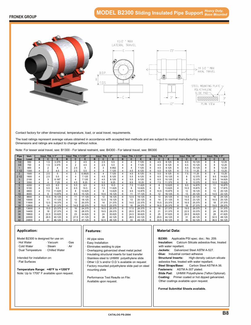
B8
Heavy Duty,Base Mounted MODEL B2300 Sliding Insulated Pipe Support
Application:
Model B2300 is designed for use on:
· Hot Water · Vacuum · Gas
· Cold Water · Steam · Air
· Dual Temperature · Chilled Water
Intended for installation on:
· Flat Surfaces
Temperature Range: +40°F to +1200°F
Note: Up to 1700° F available upon request.
Features:
· All pipe sizes
· Easy Installation
· Eliminates welding to pipe
· Overlapping galvanized sheet metal jacket
· Insulating structural inserts for load transfer
· Stainless steel to UHMW polyethylene slide
· Other I.D.'s and/or O.D.'s available on request
· Factory mounted polyethylene slide pad on steel
mounting plate
Performance Test Results on File:
Available upon request.
Material Data:
· B2300: Applicable PSI spec. doc.: No. 209.
· Insulation: Calcium Silicate asbestos-free, treated
with water repellant.
· Jackets: Galvanized Steel ASTM A-527.
· Glue: Industrial contact adhesive
· Structural Inserts: High-density calcium silicate
asbestos free, treated with water repellant.
· Steel Straps/Base: Carbon Steel ASTM A-36.
· Fasteners: ASTM A-307 plated.
· Slide Pad: UHMW Polyethylene (Teflon Optional).
· Coating: Primer coated or hot dipped galvanized.
Other coatings available upon request.
Formal Submittal Sheets available.
FRONEK GROUP
CATALOG PS-2004
Contact factory for other dimensional, temperature, load, or axial travel, requirements.
The load ratings represent average values obtained in accordance with accepted test methods and are subject to normal manufacturing variations.
Dimensions and ratings are subject to change without notice.
Note: For lesser axial travel, see: B1300 - For lateral restraint, see: B4300 - For lateral travel, see: B6300
Pipe Vert.Size Load B C E B C E B C E B C E B C E B C E B C E
1/2 550 4 1.5 3.375 4 2 4.5 4 2.5 5.5 4 4 7.125 6 4.5 8.125 6 6.5 10.125 8 8 12.25 3/4 700 4 1.5 3.375 4 2 4.5 4 2.5 5.5 4 4 7.125 6 4.5 8.125 6 6.5 10.125 8 8 12.251 900 4 2 4 4 2.5 5 4 3 6.062 4 4 7.125 6 4.5 8.125 6 6.5 10.125 8 8 12.25
1 1/2 1300 4 2 4.5 4 2.5 5.5 4 4 7.125 4 4.5 8.125 6 5.5 9.125 6 7.5 11.25 8 9 13.252 1500 4 2.5 5 4 3 6.0625 4 4 7.125 4 4.5 8.125 6 5.5 9.125 6 7.5 11.25 8 9 13.25
2 1/2 1800 4 2.5 5.5 4 4 7.125 4 4.5 8.125 4 5.5 9.125 6 6.5 10.125 6 8 12.375 8 9.5 14.6253 2100 4 3 6.187 4 4 7.125 4 4.5 8.125 4 5.5 9.125 6 6.5 10.125 6 8 12.375 8 9.5 14.6254 3350 4 4 7.25 4 4.5 8.25 4 5.5 9.25 4 6.5 10.25 6 7.5 11.375 6 9 13.375 8 10.5 15.6255 4200 4 4.5 8.5 4 5.5 9.5 4 6.5 10.5 4 7.5 11.625 6 8 12.625 6 9.5 14.875 8 11 16.8756 5100 4 5.5 9.5 4 6.5 10.5 4 7.5 11.625 4 8 12.625 6 9 13.625 6 10.5 15.875 8 12 17.8758 6800 4 7.5 11.625 4 8 12.625 4 9 13.625 6 9.5 14.875 6 10.5 15.875 6 12 18.125 8 13 20.12510 8000 4 9 13.875 4 9.5 15.125 4 10.5 16.125 6 11 17.125 6 12 18.125 6 13 20.125 8 14.5 22.12512 8800 4 10.5 16.125 4 11 17.125 4 12 18.125 6 12.5 19.125 6 13 20.125 6 14.5 22.125 8 16 24.12514 10000 4 11 17.125 4 12 18.125 4 12.5 19.125 6 13 20.125 6 14 21.125 6 15.5 23.125 8 16.5 25.12516 11600 4 12.5 19.375 4 13 20.375 6 14 21.375 6 14.5 22.375 6 15.5 23.375 8 16.5 25.375 8 18 27.37518 12800 4 14 21.375 4 14.5 22.375 6 15.5 23.375 6 16 24.375 6 16.5 25.375 8 18 27.375 8 19.5 29.37520 13600 4 15.5 23.375 4 16 24.375 6 16.5 25.375 6 17.5 26.375 6 18 27.375 8 19.5 29.375 8 21 31.37524 14400 4 18 27.375 4 19 28.375 6 19.5 29.375 6 20.5 30.375 6 21 31.375 8 22.5 33.375 8 24 35.37530 18800 4 22.5 33.625 6 23 34.625 6 24 35.625 6 24.5 36.625 6 25 37.625 8 26.5 39.625 8 28 41.62536 22000 4 26.5 40.125 6 27.5 41.125 6 28 42.125 6 28.5 43.125 6 29.5 44.125 8 31 46.125 8 32.5 48.12542 24800 4 31 46.125 6 31.5 47.125 6 32.5 48.125 6 33 49.125 6 33.5 50.125 8 35 52.125 8 36.5 54.125
Insul. Thk. = 3" Insul. Thk. =4" Insul. Thk. = 5"Insul. Thk. = 1" Insul. Thk. = 1-1/2" Insul. Thk. = 2" Insul. Thk. = 2-1/2"

B9
Heavy Duty,Base Mounted MODEL B3000 Guided Insulated Pipe Support
Application:
Model B3000 is designed for use on:
· Hot Water · Vacuum · Gas
· Cold Water · Steam · Air
· Dual Temperature · Chilled Water
Intended for installation on:
· Flat Surfaces
Temperature Range: +40°F to +1200°F
Note: Up to 1700° F available upon request.
Features:
· All pipe sizes
· Easy Installation
· Eliminates welding to pipe
· Overlapping galvanized sheet metal jacket
· Insulating structural inserts for load transfer
· Stainless steel to UHMW polyethylene slide
· Other I.D.'s and/or O.D.'s available on request
· Factory mounted polyethylene slide pad on steel
mounting plate
Performance Test Results on File:
Available upon request.
Material Data:
· B3000: Applicable PSI spec. doc.: No. 209.
· Insulation: Calcium Silicate asbestos-free, treated
with water repellant.
· Jackets: Galvanized Steel ASTM A-527.
· Glue: Industrial contact adhesive
· Structural Inserts: High-density calcium silicate
asbestos free, treated with water repellant.
· Steel Straps/Base: Carbon Steel ASTM A-36.
· Fasteners: ASTM A-307 plated.
· Slide Pad: UHMW Polyethylene (Teflon Optional).
· Coating: Primer coated or hot dipped galvanized.
Other coatings available upon request.
Formal Submittal Sheets available.
FRONEK GROUP
CATALOG PS-2004
Contact factory for other dimensional, temperature, load, or axial travel, requirements. If lateral load is greater than 20% of vertical load, contact factory.
The load ratings represent average values obtained in accordance with accepted test methods and are subject to normal manufacturing variations.
Dimensions and ratings are subject to change without notice.
Note: For higher load ratings, see: B3100 - For greater axial travel, see: B4000 - For lateral travel, see: B5000
Pipe Vert.Size Load B C E B C E B C E B C E B C E B C E B C E
1/2 140 4 6 3.25 4 6.5 4.375 4 7 5.375 4 8.5 7 6 9 8 6 11 10 8 12.5 12.125 3/4 175 4 6 3.25 4 6.5 4.375 4 7 5.375 4 8.5 7 6 9 8 6 11 10 8 12.5 12.1251 225 4 6.5 3.875 4 7 4.875 4 7.5 5.937 4 8.5 7 6 9 8 6 11 10 8 12.5 12.25
1 1/2 325 4 6.5 4.375 4 7 5.5 4 8.5 7 4 9 8 6 10 9 6 12 11.25 8 13.5 13.252 375 4 7 5 4 7.5 6.0625 4 8.5 7 4 9 8 6 10 9.125 6 12 11.25 8 13.5 13.25
2 1/2 460 4 7 5.5 4 8.5 7.125 4 9 8.125 4 10 9.125 6 11 10.125 6 12.5 12.25 8 14 14.53 530 4 7.5 6.062 4 8.5 7.125 4 9 8.125 4 10 9.125 6 11 10.125 6 12.5 12.375 8 14 14.6254 840 4 8.5 7.25 4 9 8.25 4 10 9.25 4 11 10.25 6 12 11.375 6 13.5 13.375 8 15 15.6255 1050 4 10 8.25 4 11 9.25 4 12 10.25 4 13 11.375 6 13.5 12.375 6 15 14.875 8 16.5 16.8756 1275 4 11 9.25 4 12 10.25 4 13 11.375 4 13.5 12.625 6 14.5 13.625 6 16 15.875 8 17.5 17.8758 1700 4 13.5 11.625 4 14 12.625 4 15 13.625 6 15.5 14.875 6 16.5 15.875 6 18 17.875 8 19 20.12510 2000 4 15 13.625 4 15.5 14.875 4 16.5 15.875 6 17 16.875 6 18 18.125 6 19 20.125 8 20.5 22.12512 2200 4 17 16.125 4 17.5 17.125 4 18.5 18.125 6 19 19.125 6 19.5 20.125 6 21 22.125 8 22.5 24.12514 2500 4 17.5 17.125 4 18.5 18.125 4 19 19.125 6 19.5 20.125 6 20.5 21.125 6 22 23.125 8 23 25.12516 2900 4 20.5 19.125 4 21 20.125 6 22 21.375 6 22.5 22.375 6 23.5 23.375 8 24.5 25.375 8 26 27.37518 3200 4 22 21.375 4 22.5 22.375 6 23.5 23.375 6 24 24.375 6 24.5 25.375 8 26 27.375 8 27.5 29.37520 3400 4 23.5 23.375 4 24 24.375 6 24.5 25.375 6 25.5 26.375 6 26 27.375 8 27.5 29.375 8 29 31.37524 3600 4 26 27.375 4 27 28.375 6 27.5 29.375 6 28.5 30.375 6 29 31.375 8 30.5 33.375 8 32 35.37530 4700 4 32.5 33.625 6 33 34.625 6 34 35.625 6 34.5 36.625 6 35 37.625 8 36.5 39.625 8 38 41.62536 5500 4 36.5 39.625 6 37.5 41.125 6 38 42.125 6 38.5 43.125 6 39.5 44.125 8 41 46.125 8 42.5 48.12542 6200 4 41 46.125 6 41.5 47.125 6 42.5 48.125 6 43 49.125 6 43.5 50.125 8 45 52.125 8 46.5 54.125
Insul. Thk. = 3" Insul. Thk. =4" Insul. Thk. = 5"Insul. Thk. = 1" Insul. Thk. = 1-1/2" Insul. Thk. = 2" Insul. Thk. = 2-1/2"

B10
Heavy Duty,Base Mounted MODEL B3100 Guided Insulated Pipe Support
Application:
Model B3100 is designed for use on:
· Hot Water · Vacuum · Gas
· Cold Water · Steam · Air
· Dual Temperature · Chilled Water
Intended for installation on:
· Flat Surfaces
Temperature Range: +40°F to +1200°F
Note: Up to 1700° F available upon request.
Features:
· All pipe sizes
· Easy Installation
· Eliminates welding to pipe
· Overlapping galvanized sheet metal jacket
· Insulating structural inserts for load transfer
· Stainless steel to UHMW polyethylene slide
· Other I.D.'s and/or O.D.'s available on request
· Factory mounted polyethylene slide pad on steel
mounting plate
Performance Test Results on File:
Available upon request.
Material Data:
· B3100: Applicable PSI spec. doc.: No. 209.
· Insulation: Calcium Silicate asbestos-free, treated
with water repellant.
· Jackets: Galvanized Steel ASTM A-527.
· Glue: Industrial contact adhesive
· Structural Inserts: High-density calcium silicate
asbestos free, treated with water repellant.
· Steel Straps/Base: Carbon Steel ASTM A-36.
· Fasteners: ASTM A-307 plated.
· Slide Pad: UHMW Polyethylene (Teflon Optional).
· Coating: Primer coated or hot dipped galvanized.
Other coatings available upon request.
Formal Submittal Sheets available.
FRONEK GROUP
CATALOG PS-2004
Contact factory for other dimensional, temperature, load, or axial travel, requirements. If lateral load is greater than 20% of vertical load, contact factory.
The load ratings represent average values obtained in accordance with accepted test methods and are subject to normal manufacturing variations.
Dimensions and ratings are subject to change without notice.
Note: For higher load ratings, see: B3200 - For greater axial travel, see: B4100 - For lateral travel, see: B5100
Pipe Vert.Size Load B C E B C E B C E B C E B C E B C E B C E
1/2 280 4 6 3.25 4 6.5 4.375 4 7 5.375 4 8.5 7 6 9 8 6 11 10 8 12.5 12.125 3/4 350 4 6 3.25 4 6.5 4.375 4 7 5.375 4 8.5 7 6 9 8 6 11 10 8 12.5 12.251 450 4 6.5 3.875 4 7 5 4 7.5 6.062 4 8.5 7 6 9 8 6 11 10 8 12.5 12.25
1 1/2 650 4 6.5 4.5 4 7 5.5 4 8.5 7.125 4 9 8.125 6 10 9.125 6 12 11.25 8 13.5 13.252 750 4 7 5 4 7.5 6.0625 4 8.5 7.125 4 9 8.125 6 10 9.125 6 12 11.25 8 13.5 13.25
2 1/2 920 4 7 5.5 4 8.5 7.125 4 9 8.125 4 10 9.125 6 11 10.125 6 12.5 12.25 8 14 14.53 1060 4 7.5 6.187 4 8.5 7.125 4 9 8.125 4 10 9.125 6 11 10.125 6 12.5 12.375 8 14 14.6254 1680 4 8.5 7.25 4 9 8.25 4 10 9.25 4 11 10.25 6 12 11.375 6 13.5 13.375 8 15 15.6255 2100 4 10 8.5 4 11 9.5 4 12 10.5 4 13 11.625 6 13.5 12.625 6 15 14.875 8 16.5 16.8756 2550 4 11 9.5 4 12 10.5 4 13 11.625 4 13.5 12.625 6 14.5 13.625 6 16 15.875 8 17.5 17.8758 3400 4 13.5 11.625 4 14 12.625 4 15 13.625 6 15.5 14.875 6 16.5 15.875 6 18 18.125 8 19 20.12510 4000 4 15 13.875 4 15.5 15.125 4 16.5 16.125 6 17 17.125 6 18 18.125 6 19 20.125 8 20.5 22.12512 4400 4 17 16.125 4 17.5 17.125 4 18.5 18.125 6 19 19.125 6 19.5 20.125 6 21 22.125 8 22.5 24.12514 5000 4 17.5 17.125 4 18.5 18.125 4 19 19.125 6 19.5 20.125 6 20.5 21.125 6 22 23.125 8 23 25.12516 5800 4 20.5 19.375 4 21 20.375 6 22 21.375 6 22.5 22.375 6 23.5 23.375 8 24.5 25.375 8 26 27.37518 6400 4 22 21.375 4 22.5 22.375 6 23.5 23.375 6 24 24.375 6 24.5 25.375 8 26 27.375 8 27.5 29.37520 6800 4 23.5 23.375 4 24 24.375 6 24.5 25.375 6 25.5 26.375 6 26 27.375 8 27.5 29.375 8 29 31.37524 7200 4 26 27.375 4 27 28.375 6 27.5 29.375 6 28.5 30.375 6 29 31.375 8 30.5 33.375 8 32 35.37530 9400 4 32.5 33.625 6 33 34.625 6 34 35.625 6 34.5 36.625 6 35 37.625 8 36.5 39.625 8 38 41.62536 11000 4 36.5 40.125 6 37.5 41.125 6 38 42.125 6 38.5 43.125 6 39.5 44.125 8 41 46.125 8 42.5 48.12542 12400 4 41 46.125 6 41.5 47.125 6 42.5 48.125 6 43 49.125 6 43.5 50.125 8 45 52.125 8 46.5 54.125
Insul. Thk. = 3" Insul. Thk. =4" Insul. Thk. = 5"Insul. Thk. = 1" Insul. Thk. = 1-1/2" Insul. Thk. = 2" Insul. Thk. = 2-1/2"
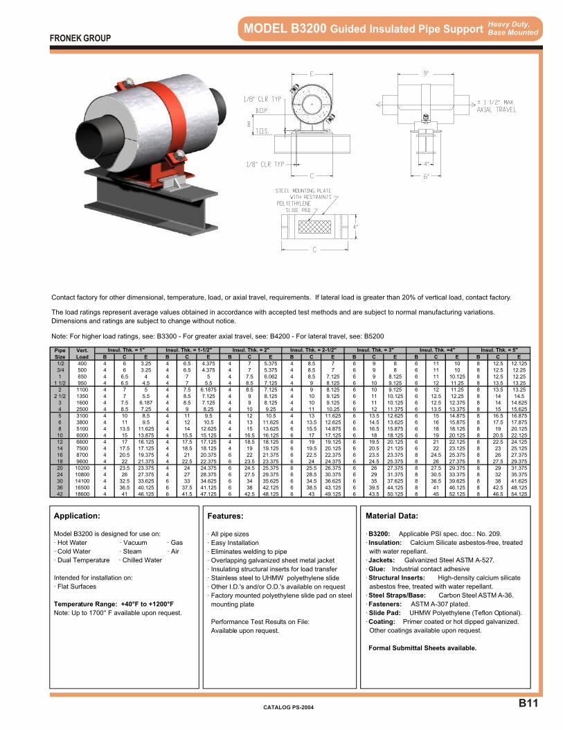
B11
Heavy Duty,Base Mounted MODEL B3200 Guided Insulated Pipe Support
Application:
Model B3200 is designed for use on:
· Hot Water · Vacuum · Gas
· Cold Water · Steam · Air
· Dual Temperature · Chilled Water
Intended for installation on:
· Flat Surfaces
Temperature Range: +40°F to +1200°F
Note: Up to 1700° F available upon request.
Features:
· All pipe sizes
· Easy Installation
· Eliminates welding to pipe
· Overlapping galvanized sheet metal jacket
· Insulating structural inserts for load transfer
· Stainless steel to UHMW polyethylene slide
· Other I.D.'s and/or O.D.'s available on request
· Factory mounted polyethylene slide pad on steel
mounting plate
Performance Test Results on File:
Available upon request.
Material Data:
· B3200: Applicable PSI spec. doc.: No. 209.
· Insulation: Calcium Silicate asbestos-free, treated
with water repellant.
· Jackets: Galvanized Steel ASTM A-527.
· Glue: Industrial contact adhesive
· Structural Inserts: High-density calcium silicate
asbestos free, treated with water repellant.
· Steel Straps/Base: Carbon Steel ASTM A-36.
· Fasteners: ASTM A-307 plated.
· Slide Pad: UHMW Polyethylene (Teflon Optional).
· Coating: Primer coated or hot dipped galvanized.
Other coatings available upon request.
Formal Submittal Sheets available.
FRONEK GROUP
CATALOG PS-2004
Contact factory for other dimensional, temperature, load, or axial travel, requirements. If lateral load is greater than 20% of vertical load, contact factory.
The load ratings represent average values obtained in accordance with accepted test methods and are subject to normal manufacturing variations.
Dimensions and ratings are subject to change without notice.
Note: For higher load ratings, see: B3300 - For greater axial travel, see: B4200 - For lateral travel, see: B5200
Pipe Vert.Size Load B C E B C E B C E B C E B C E B C E B C E
1/2 400 4 6 3.25 4 6.5 4.375 4 7 5.375 4 8.5 7 6 9 8 6 11 10 8 12.5 12.125 3/4 500 4 6 3.25 4 6.5 4.375 4 7 5.375 4 8.5 7 6 9 8 6 11 10 8 12.5 12.251 650 4 6.5 4 4 7 5 4 7.5 6.062 4 8.5 7.125 6 9 8.125 6 11 10.125 8 12.5 12.25
1 1/2 950 4 6.5 4.5 4 7 5.5 4 8.5 7.125 4 9 8.125 6 10 9.125 6 12 11.25 8 13.5 13.252 1100 4 7 5 4 7.5 6.1875 4 8.5 7.125 4 9 8.125 6 10 9.125 6 12 11.25 8 13.5 13.25
2 1/2 1350 4 7 5.5 4 8.5 7.125 4 9 8.125 4 10 9.125 6 11 10.125 6 12.5 12.25 8 14 14.53 1600 4 7.5 6.187 4 8.5 7.125 4 9 8.125 4 10 9.125 6 11 10.125 6 12.5 12.375 8 14 14.6254 2500 4 8.5 7.25 4 9 8.25 4 10 9.25 4 11 10.25 6 12 11.375 6 13.5 13.375 8 15 15.6255 3100 4 10 8.5 4 11 9.5 4 12 10.5 4 13 11.625 6 13.5 12.625 6 15 14.875 8 16.5 16.8756 3800 4 11 9.5 4 12 10.5 4 13 11.625 4 13.5 12.625 6 14.5 13.625 6 16 15.875 8 17.5 17.8758 5100 4 13.5 11.625 4 14 12.625 4 15 13.625 6 15.5 14.875 6 16.5 15.875 6 18 18.125 8 19 20.12510 6000 4 15 13.875 4 15.5 15.125 4 16.5 16.125 6 17 17.125 6 18 18.125 6 19 20.125 8 20.5 22.12512 6600 4 17 16.125 4 17.5 17.125 4 18.5 18.125 6 19 19.125 6 19.5 20.125 6 21 22.125 8 22.5 24.12514 7500 4 17.5 17.125 4 18.5 18.125 4 19 19.125 6 19.5 20.125 6 20.5 21.125 6 22 23.125 8 23 25.12516 8700 4 20.5 19.375 4 21 20.375 6 22 21.375 6 22.5 22.375 6 23.5 23.375 8 24.5 25.375 8 26 27.37518 9600 4 22 21.375 4 22.5 22.375 6 23.5 23.375 6 24 24.375 6 24.5 25.375 8 26 27.375 8 27.5 29.37520 10200 4 23.5 23.375 4 24 24.375 6 24.5 25.375 6 25.5 26.375 6 26 27.375 8 27.5 29.375 8 29 31.37524 10800 4 26 27.375 4 27 28.375 6 27.5 29.375 6 28.5 30.375 6 29 31.375 8 30.5 33.375 8 32 35.37530 14100 4 32.5 33.625 6 33 34.625 6 34 35.625 6 34.5 36.625 6 35 37.625 8 36.5 39.625 8 38 41.62536 16500 4 36.5 40.125 6 37.5 41.125 6 38 42.125 6 38.5 43.125 6 39.5 44.125 8 41 46.125 8 42.5 48.12542 18600 4 41 46.125 6 41.5 47.125 6 42.5 48.125 6 43 49.125 6 43.5 50.125 8 45 52.125 8 46.5 54.125
Insul. Thk. = 3" Insul. Thk. =4" Insul. Thk. = 5"Insul. Thk. = 1" Insul. Thk. = 1-1/2" Insul. Thk. = 2" Insul. Thk. = 2-1/2"
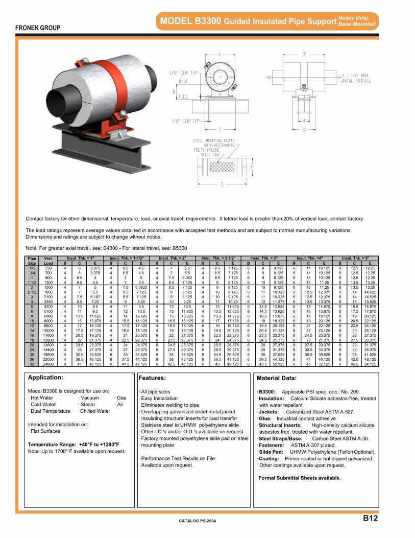
B12
Heavy Duty,Base Mounted MODEL B3300 Guided Insulated Pipe Support
Application:
Model B3300 is designed for use on:
· Hot Water · Vacuum · Gas
· Cold Water · Steam · Air
· Dual Temperature · Chilled Water
Intended for installation on:
· Flat Surfaces
Temperature Range: +40°F to +1200°F
Note: Up to 1700° F available upon request.
Features:
· All pipe sizes
· Easy Installation
· Eliminates welding to pipe
· Overlapping galvanized sheet metal jacket
· Insulating structural inserts for load transfer
· Stainless steel to UHMW polyethylene slide
· Other I.D.'s and/or O.D.'s available on request
· Factory mounted polyethylene slide pad on steel
mounting plate
Performance Test Results on File:
Available upon request.
Material Data:
· B3300: Applicable PSI spec. doc.: No. 209.
· Insulation: Calcium Silicate asbestos-free, treated
with water repellant.
· Jackets: Galvanized Steel ASTM A-527.
· Glue: Industrial contact adhesive
· Structural Inserts: High-density calcium silicate
asbestos free, treated with water repellant.
· Steel Straps/Base: Carbon Steel ASTM A-36.
· Fasteners: ASTM A-307 plated.
· Slide Pad: UHMW Polyethylene (Teflon Optional).
· Coating: Primer coated or hot dipped galvanized.
Other coatings available upon request.
Formal Submittal Sheets available.
FRONEK GROUP
CATALOG PS-2004
Contact factory for other dimensional, temperature, load, or axial travel, requirements. If lateral load is greater than 20% of vertical load, contact factory.
The load ratings represent average values obtained in accordance with accepted test methods and are subject to normal manufacturing variations.
Dimensions and ratings are subject to change without notice.
Note: For greater axial travel, see: B4300 - For lateral travel, see: B5300
Pipe Vert.Size Load B C E B C E B C E B C E B C E B C E B C E
1/2 550 4 6 3.375 4 6.5 4.5 4 7 5.5 4 8.5 7.125 6 9 8.125 6 11 10.125 8 12.5 12.25 3/4 700 4 6 3.375 4 6.5 4.5 4 7 5.5 4 8.5 7.125 6 9 8.125 6 11 10.125 8 12.5 12.251 900 4 6.5 4 4 7 5 4 7.5 6.062 4 8.5 7.125 6 9 8.125 6 11 10.125 8 12.5 12.25
1 1/2 1300 4 6.5 4.5 4 7 5.5 4 8.5 7.125 4 9 8.125 6 10 9.125 6 12 11.25 8 13.5 13.252 1500 4 7 5 4 7.5 6.0625 4 8.5 7.125 4 9 8.125 6 10 9.125 6 12 11.25 8 13.5 13.25
2 1/2 1800 4 7 5.5 4 8.5 7.125 4 9 8.125 4 10 9.125 6 11 10.125 6 12.5 12.375 8 14 14.6253 2100 4 7.5 6.187 4 8.5 7.125 4 9 8.125 4 10 9.125 6 11 10.125 6 12.5 12.375 8 14 14.6254 3350 4 8.5 7.25 4 9 8.25 4 10 9.25 4 11 10.25 6 12 11.375 6 13.5 13.375 8 15 15.6255 4200 4 10 8.5 4 11 9.5 4 12 10.5 4 13 11.625 6 13.5 12.625 6 15 14.875 8 16.5 16.8756 5100 4 11 9.5 4 12 10.5 4 13 11.625 4 13.5 12.625 6 14.5 13.625 6 16 15.875 8 17.5 17.8758 6800 4 13.5 11.625 4 14 12.625 4 15 13.625 6 15.5 14.875 6 16.5 15.875 6 18 18.125 8 19 20.12510 8000 4 15 13.875 4 15.5 15.125 4 16.5 16.125 6 17 17.125 6 18 18.125 6 19 20.125 8 20.5 22.12512 8800 4 17 16.125 4 17.5 17.125 4 18.5 18.125 6 19 19.125 6 19.5 20.125 6 21 22.125 8 22.5 24.12514 10000 4 17.5 17.125 4 18.5 18.125 4 19 19.125 6 19.5 20.125 6 20.5 21.125 6 22 23.125 8 23 25.12516 11600 4 20.5 19.375 4 21 20.375 6 22 21.375 6 22.5 22.375 6 23.5 23.375 8 24.5 25.375 8 26 27.37518 12800 4 22 21.375 4 22.5 22.375 6 23.5 23.375 6 24 24.375 6 24.5 25.375 8 26 27.375 8 27.5 29.37520 13600 4 23.5 23.375 4 24 24.375 6 24.5 25.375 6 25.5 26.375 6 26 27.375 8 27.5 29.375 8 29 31.37524 14400 4 26 27.375 4 27 28.375 6 27.5 29.375 6 28.5 30.375 6 29 31.375 8 30.5 33.375 8 32 35.37530 18800 4 32.5 33.625 6 33 34.625 6 34 35.625 6 34.5 36.625 6 35 37.625 8 36.5 39.625 8 38 41.62536 22000 4 36.5 40.125 6 37.5 41.125 6 38 42.125 6 38.5 43.125 6 39.5 44.125 8 41 46.125 8 42.5 48.12542 24800 4 41 46.125 6 41.5 47.125 6 42.5 48.125 6 43 49.125 6 43.5 50.125 8 45 52.125 8 46.5 54.125
Insul. Thk. = 3" Insul. Thk. =4" Insul. Thk. = 5"Insul. Thk. = 1" Insul. Thk. = 1-1/2" Insul. Thk. = 2" Insul. Thk. = 2-1/2"
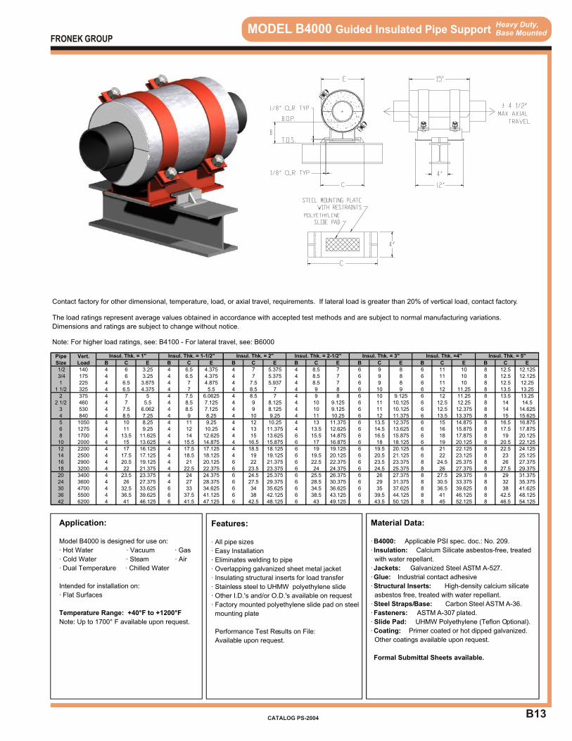
B13
Heavy Duty,Base Mounted MODEL B4000 Guided Insulated Pipe Support
Application:
Model B4000 is designed for use on:
· Hot Water · Vacuum · Gas
· Cold Water · Steam · Air
· Dual Temperature · Chilled Water
Intended for installation on:
· Flat Surfaces
Temperature Range: +40°F to +1200°F
Note: Up to 1700° F available upon request.
Features:
· All pipe sizes
· Easy Installation
· Eliminates welding to pipe
· Overlapping galvanized sheet metal jacket
· Insulating structural inserts for load transfer
· Stainless steel to UHMW polyethylene slide
· Other I.D.'s and/or O.D.'s available on request
· Factory mounted polyethylene slide pad on steel
mounting plate
Performance Test Results on File:
Available upon request.
Material Data:
· B4000: Applicable PSI spec. doc.: No. 209.
· Insulation: Calcium Silicate asbestos-free, treated
with water repellant.
· Jackets: Galvanized Steel ASTM A-527.
· Glue: Industrial contact adhesive
· Structural Inserts: High-density calcium silicate
asbestos free, treated with water repellant.
· Steel Straps/Base: Carbon Steel ASTM A-36.
· Fasteners: ASTM A-307 plated.
· Slide Pad: UHMW Polyethylene (Teflon Optional).
· Coating: Primer coated or hot dipped galvanized.
Other coatings available upon request.
Formal Submittal Sheets available.
FRONEK GROUP
CATALOG PS-2004
Contact factory for other dimensional, temperature, load, or axial travel, requirements. If lateral load is greater than 20% of vertical load, contact factory.
The load ratings represent average values obtained in accordance with accepted test methods and are subject to normal manufacturing variations.
Dimensions and ratings are subject to change without notice.
Note: For higher load ratings, see: B4100 - For lateral travel, see: B6000
Pipe Vert.Size Load B C E B C E B C E B C E B C E B C E B C E
1/2 140 4 6 3.25 4 6.5 4.375 4 7 5.375 4 8.5 7 6 9 8 6 11 10 8 12.5 12.125 3/4 175 4 6 3.25 4 6.5 4.375 4 7 5.375 4 8.5 7 6 9 8 6 11 10 8 12.5 12.1251 225 4 6.5 3.875 4 7 4.875 4 7.5 5.937 4 8.5 7 6 9 8 6 11 10 8 12.5 12.25
1 1/2 325 4 6.5 4.375 4 7 5.5 4 8.5 7 4 9 8 6 10 9 6 12 11.25 8 13.5 13.252 375 4 7 5 4 7.5 6.0625 4 8.5 7 4 9 8 6 10 9.125 6 12 11.25 8 13.5 13.25
2 1/2 460 4 7 5.5 4 8.5 7.125 4 9 8.125 4 10 9.125 6 11 10.125 6 12.5 12.25 8 14 14.53 530 4 7.5 6.062 4 8.5 7.125 4 9 8.125 4 10 9.125 6 11 10.125 6 12.5 12.375 8 14 14.6254 840 4 8.5 7.25 4 9 8.25 4 10 9.25 4 11 10.25 6 12 11.375 6 13.5 13.375 8 15 15.6255 1050 4 10 8.25 4 11 9.25 4 12 10.25 4 13 11.375 6 13.5 12.375 6 15 14.875 8 16.5 16.8756 1275 4 11 9.25 4 12 10.25 4 13 11.375 4 13.5 12.625 6 14.5 13.625 6 16 15.875 8 17.5 17.8758 1700 4 13.5 11.625 4 14 12.625 4 15 13.625 6 15.5 14.875 6 16.5 15.875 6 18 17.875 8 19 20.12510 2000 4 15 13.625 4 15.5 14.875 4 16.5 15.875 6 17 16.875 6 18 18.125 6 19 20.125 8 20.5 22.12512 2200 4 17 16.125 4 17.5 17.125 4 18.5 18.125 6 19 19.125 6 19.5 20.125 6 21 22.125 8 22.5 24.12514 2500 4 17.5 17.125 4 18.5 18.125 4 19 19.125 6 19.5 20.125 6 20.5 21.125 6 22 23.125 8 23 25.12516 2900 4 20.5 19.125 4 21 20.125 6 22 21.375 6 22.5 22.375 6 23.5 23.375 8 24.5 25.375 8 26 27.37518 3200 4 22 21.375 4 22.5 22.375 6 23.5 23.375 6 24 24.375 6 24.5 25.375 8 26 27.375 8 27.5 29.37520 3400 4 23.5 23.375 4 24 24.375 6 24.5 25.375 6 25.5 26.375 6 26 27.375 8 27.5 29.375 8 29 31.37524 3600 4 26 27.375 4 27 28.375 6 27.5 29.375 6 28.5 30.375 6 29 31.375 8 30.5 33.375 8 32 35.37530 4700 4 32.5 33.625 6 33 34.625 6 34 35.625 6 34.5 36.625 6 35 37.625 8 36.5 39.625 8 38 41.62536 5500 4 36.5 39.625 6 37.5 41.125 6 38 42.125 6 38.5 43.125 6 39.5 44.125 8 41 46.125 8 42.5 48.12542 6200 4 41 46.125 6 41.5 47.125 6 42.5 48.125 6 43 49.125 6 43.5 50.125 8 45 52.125 8 46.5 54.125
Insul. Thk. = 3" Insul. Thk. =4" Insul. Thk. = 5"Insul. Thk. = 1" Insul. Thk. = 1-1/2" Insul. Thk. = 2" Insul. Thk. = 2-1/2"
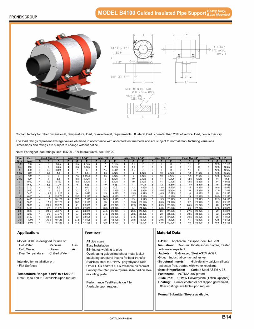
B14
Heavy Duty,Base Mounted MODEL B4100 Guided Insulated Pipe Support
Application:
Model B4100 is designed for use on:
· Hot Water · Vacuum · Gas
· Cold Water · Steam · Air
· Dual Temperature · Chilled Water
Intended for installation on:
· Flat Surfaces
Temperature Range: +40°F to +1200°F
Note: Up to 1700° F available upon request.
Features:
· All pipe sizes
· Easy Installation
· Eliminates welding to pipe
· Overlapping galvanized sheet metal jacket
· Insulating structural inserts for load transfer
· Stainless steel to UHMW polyethylene slide
· Other I.D.'s and/or O.D.'s available on request
· Factory mounted polyethylene slide pad on steel
mounting plate
Performance Test Results on File:
Available upon request.
Material Data:
· B4100: Applicable PSI spec. doc.: No. 209.
· Insulation: Calcium Silicate asbestos-free, treated
with water repellant.
· Jackets: Galvanized Steel ASTM A-527.
· Glue: Industrial contact adhesive
· Structural Inserts: High-density calcium silicate
asbestos free, treated with water repellant.
· Steel Straps/Base: Carbon Steel ASTM A-36.
· Fasteners: ASTM A-307 plated.
· Slide Pad: UHMW Polyethylene (Teflon Optional).
· Coating: Primer coated or hot dipped galvanized.
Other coatings available upon request.
Formal Submittal Sheets available.
FRONEK GROUP
CATALOG PS-2004
Contact factory for other dimensional, temperature, load, or axial travel, requirements. If lateral load is greater than 20% of vertical load, contact factory.
The load ratings represent average values obtained in accordance with accepted test methods and are subject to normal manufacturing variations.
Dimensions and ratings are subject to change without notice.
Note: For higher load ratings, see: B4200 - For lateral travel, see: B6100
Pipe Vert.Size Load B C E B C E B C E B C E B C E B C E B C E
1/2 280 4 6 3.25 4 6.5 4.375 4 7 5.375 4 8.5 7 6 9 8 6 11 10 8 12.5 12.125 3/4 350 4 6 3.25 4 6.5 4.375 4 7 5.375 4 8.5 7 6 9 8 6 11 10 8 12.5 12.251 450 4 6.5 3.875 4 7 5 4 7.5 6.062 4 8.5 7 6 9 8 6 11 10 8 12.5 12.25
1 1/2 650 4 6.5 4.5 4 7 5.5 4 8.5 7.125 4 9 8.125 6 10 9.125 6 12 11.25 8 13.5 13.252 750 4 7 5 4 7.5 6.0625 4 8.5 7.125 4 9 8.125 6 10 9.125 6 12 11.25 8 13.5 13.25
2 1/2 920 4 7 5.5 4 8.5 7.125 4 9 8.125 4 10 9.125 6 11 10.125 6 12.5 12.25 8 14 14.53 1060 4 7.5 6.187 4 8.5 7.125 4 9 8.125 4 10 9.125 6 11 10.125 6 12.5 12.375 8 14 14.6254 1680 4 8.5 7.25 4 9 8.25 4 10 9.25 4 11 10.25 6 12 11.375 6 13.5 13.375 8 15 15.6255 2100 4 10 8.5 4 11 9.5 4 12 10.5 4 13 11.625 6 13.5 12.625 6 15 14.875 8 16.5 16.8756 2550 4 11 9.5 4 12 10.5 4 13 11.625 4 13.5 12.625 6 14.5 13.625 6 16 15.875 8 17.5 17.8758 3400 4 13.5 11.625 4 14 12.625 4 15 13.625 6 15.5 14.875 6 16.5 15.875 6 18 18.125 8 19 20.12510 4000 4 15 13.875 4 15.5 15.125 4 16.5 16.125 6 17 17.125 6 18 18.125 6 19 20.125 8 20.5 22.12512 4400 4 17 16.125 4 17.5 17.125 4 18.5 18.125 6 19 19.125 6 19.5 20.125 6 21 22.125 8 22.5 24.12514 5000 4 17.5 17.125 4 18.5 18.125 4 19 19.125 6 19.5 20.125 6 20.5 21.125 6 22 23.125 8 23 25.12516 5800 4 20.5 19.375 4 21 20.375 6 22 21.375 6 22.5 22.375 6 23.5 23.375 8 24.5 25.375 8 26 27.37518 6400 4 22 21.375 4 22.5 22.375 6 23.5 23.375 6 24 24.375 6 24.5 25.375 8 26 27.375 8 27.5 29.37520 6800 4 23.5 23.375 4 24 24.375 6 24.5 25.375 6 25.5 26.375 6 26 27.375 8 27.5 29.375 8 29 31.37524 7200 4 26 27.375 4 27 28.375 6 27.5 29.375 6 28.5 30.375 6 29 31.375 8 30.5 33.375 8 32 35.37530 9400 4 32.5 33.625 6 33 34.625 6 34 35.625 6 34.5 36.625 6 35 37.625 8 36.5 39.625 8 38 41.62536 11000 4 36.5 40.125 6 37.5 41.125 6 38 42.125 6 38.5 43.125 6 39.5 44.125 8 41 46.125 8 42.5 48.12542 12400 4 41 46.125 6 41.5 47.125 6 42.5 48.125 6 43 49.125 6 43.5 50.125 8 45 52.125 8 46.5 54.125
Insul. Thk. = 3" Insul. Thk. =4" Insul. Thk. = 5"Insul. Thk. = 1" Insul. Thk. = 1-1/2" Insul. Thk. = 2" Insul. Thk. = 2-1/2"

B15
Heavy Duty,Base Mounted MODEL B4200 Guided Insulated Pipe Support
Application:
Model B4200 is designed for use on:
· Hot Water · Vacuum · Gas
· Cold Water · Steam · Air
· Dual Temperature · Chilled Water
Intended for installation on:
· Flat Surfaces
Temperature Range: +40°F to +1200°F
Note: Up to 1700° F available upon request.
Features:
· All pipe sizes
· Easy Installation
· Eliminates welding to pipe
· Overlapping galvanized sheet metal jacket
· Insulating structural inserts for load transfer
· Stainless steel to UHMW polyethylene slide
· Other I.D.'s and/or O.D.'s available on request
· Factory mounted polyethylene slide pad on steel
mounting plate
Performance Test Results on File:
Available upon request.
Material Data:
· B4200: Applicable PSI spec. doc.: No. 209.
· Insulation: Calcium Silicate asbestos-free, treated
with water repellant.
· Jackets: Galvanized Steel ASTM A-527.
· Glue: Industrial contact adhesive
· Structural Inserts: High-density calcium silicate
asbestos free, treated with water repellant.
· Steel Straps/Base: Carbon Steel ASTM A-36.
· Fasteners: ASTM A-307 plated.
· Slide Pad: UHMW Polyethylene (Teflon Optional).
· Coating: Primer coated or hot dipped galvanized.
Other coatings available upon request.
Formal Submittal Sheets available.
FRONEK GROUP
CATALOG PS-2004
Contact factory for other dimensional, temperature, load, or axial travel, requirements. If lateral load is greater than 20% of vertical load, contact factory.
The load ratings represent average values obtained in accordance with accepted test methods and are subject to normal manufacturing variations.
Dimensions and ratings are subject to change without notice.
Note: For higher load ratings, see: B4300 - For lateral travel, see: B6200
Pipe Vert.Size Load B C E B C E B C E B C E B C E B C E B C E
1/2 400 4 6 3.25 4 6.5 4.375 4 7 5.375 4 8.5 7 6 9 8 6 11 10 8 12.5 12.125 3/4 500 4 6 3.25 4 6.5 4.375 4 7 5.375 4 8.5 7 6 9 8 6 11 10 8 12.5 12.251 650 4 6.5 4 4 7 5 4 7.5 6.062 4 8.5 7.125 6 9 8.125 6 11 10.125 8 12.5 12.25
1 1/2 950 4 6.5 4.5 4 7 5.5 4 8.5 7.125 4 9 8.125 6 10 9.125 6 12 11.25 8 13.5 13.252 1100 4 7 5 4 7.5 6.1875 4 8.5 7.125 4 9 8.125 6 10 9.125 6 12 11.25 8 13.5 13.25
2 1/2 1350 4 7 5.5 4 8.5 7.125 4 9 8.125 4 10 9.125 6 11 10.125 6 12.5 12.25 8 14 14.53 1600 4 7.5 6.187 4 8.5 7.125 4 9 8.125 4 10 9.125 6 11 10.125 6 12.5 12.375 8 14 14.6254 2500 4 8.5 7.25 4 9 8.25 4 10 9.25 4 11 10.25 6 12 11.375 6 13.5 13.375 8 15 15.6255 3100 4 10 8.5 4 11 9.5 4 12 10.5 4 13 11.625 6 13.5 12.625 6 15 14.875 8 16.5 16.8756 3800 4 11 9.5 4 12 10.5 4 13 11.625 4 13.5 12.625 6 14.5 13.625 6 16 15.875 8 17.5 17.8758 5100 4 13.5 11.625 4 14 12.625 4 15 13.625 6 15.5 14.875 6 16.5 15.875 6 18 18.125 8 19 20.12510 6000 4 15 13.875 4 15.5 15.125 4 16.5 16.125 6 17 17.125 6 18 18.125 6 19 20.125 8 20.5 22.12512 6600 4 17 16.125 4 17.5 17.125 4 18.5 18.125 6 19 19.125 6 19.5 20.125 6 21 22.125 8 22.5 24.12514 7500 4 17.5 17.125 4 18.5 18.125 4 19 19.125 6 19.5 20.125 6 20.5 21.125 6 22 23.125 8 23 25.12516 8700 4 20.5 19.375 4 21 20.375 6 22 21.375 6 22.5 22.375 6 23.5 23.375 8 24.5 25.375 8 26 27.37518 9600 4 22 21.375 4 22.5 22.375 6 23.5 23.375 6 24 24.375 6 24.5 25.375 8 26 27.375 8 27.5 29.37520 10200 4 23.5 23.375 4 24 24.375 6 24.5 25.375 6 25.5 26.375 6 26 27.375 8 27.5 29.375 8 29 31.37524 10800 4 26 27.375 4 27 28.375 6 27.5 29.375 6 28.5 30.375 6 29 31.375 8 30.5 33.375 8 32 35.37530 14100 4 32.5 33.625 6 33 34.625 6 34 35.625 6 34.5 36.625 6 35 37.625 8 36.5 39.625 8 38 41.62536 16500 4 36.5 40.125 6 37.5 41.125 6 38 42.125 6 38.5 43.125 6 39.5 44.125 8 41 46.125 8 42.5 48.12542 18600 4 41 46.125 6 41.5 47.125 6 42.5 48.125 6 43 49.125 6 43.5 50.125 8 45 52.125 8 46.5 54.125
Insul. Thk. = 3" Insul. Thk. =4" Insul. Thk. = 5"Insul. Thk. = 1" Insul. Thk. = 1-1/2" Insul. Thk. = 2" Insul. Thk. = 2-1/2"
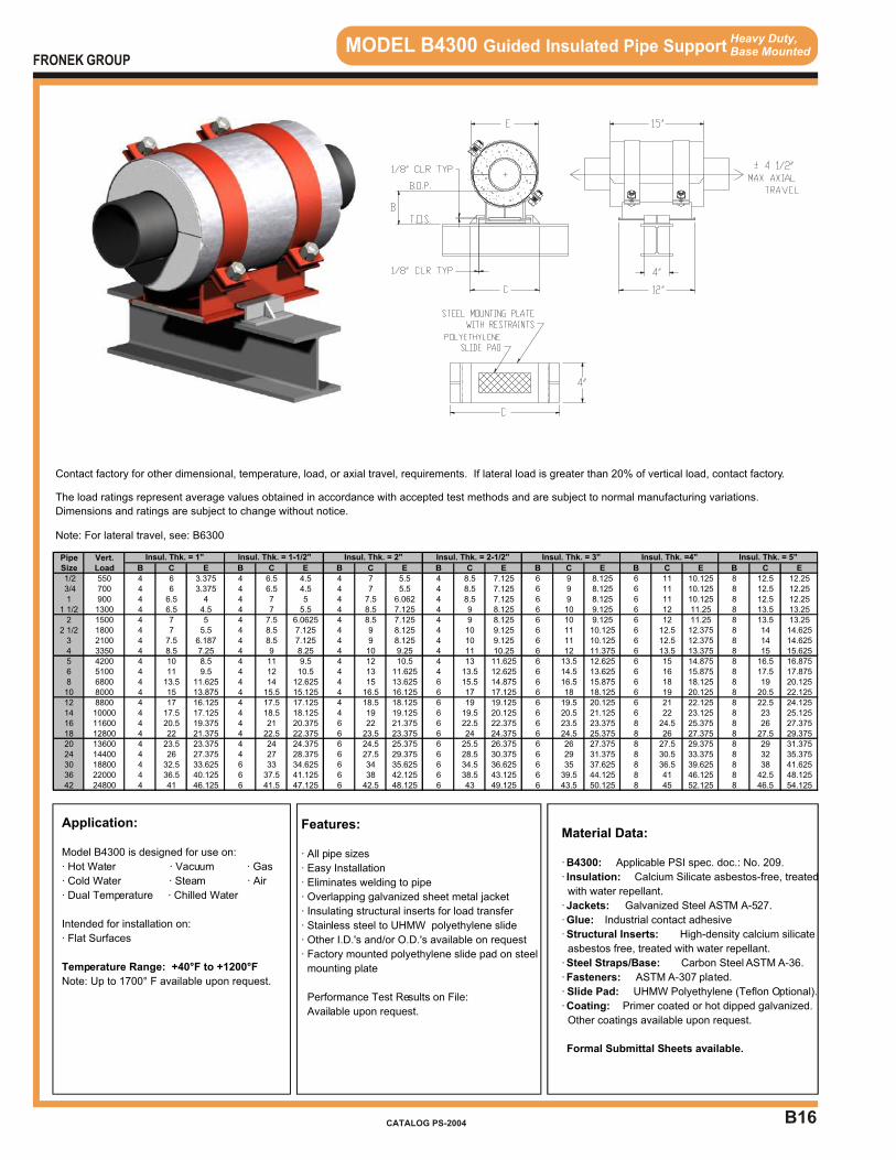
B16
MODEL B4300 Guided Insulated Pipe Support Heavy Duty,Base Mounted
Application:
Model B4300 is designed for use on:
· Hot Water · Vacuum · Gas
· Cold Water · Steam · Air
· Dual Temperature · Chilled Water
Intended for installation on:
· Flat Surfaces
Temperature Range: +40°F to +1200°F
Note: Up to 1700° F available upon request.
Features:
· All pipe sizes
· Easy Installation
· Eliminates welding to pipe
· Overlapping galvanized sheet metal jacket
· Insulating structural inserts for load transfer
· Stainless steel to UHMW polyethylene slide
· Other I.D.'s and/or O.D.'s available on request
· Factory mounted polyethylene slide pad on steel
mounting plate
Performance Test Results on File:
Available upon request.
Material Data:
· B4300: Applicable PSI spec. doc.: No. 209.
· Insulation: Calcium Silicate asbestos-free, treated
with water repellant.
· Jackets: Galvanized Steel ASTM A-527.
· Glue: Industrial contact adhesive
· Structural Inserts: High-density calcium silicate
asbestos free, treated with water repellant.
· Steel Straps/Base: Carbon Steel ASTM A-36.
· Fasteners: ASTM A-307 plated.
· Slide Pad: UHMW Polyethylene (Teflon Optional).
· Coating: Primer coated or hot dipped galvanized.
Other coatings available upon request.
Formal Submittal Sheets available.
FRONEK GROUP
CATALOG PS-2004
Contact factory for other dimensional, temperature, load, or axial travel, requirements. If lateral load is greater than 20% of vertical load, contact factory.
The load ratings represent average values obtained in accordance with accepted test methods and are subject to normal manufacturing variations.
Dimensions and ratings are subject to change without notice.
Note: For lateral travel, see: B6300
Pipe Vert.Size Load B C E B C E B C E B C E B C E B C E B C E
1/2 550 4 6 3.375 4 6.5 4.5 4 7 5.5 4 8.5 7.125 6 9 8.125 6 11 10.125 8 12.5 12.25 3/4 700 4 6 3.375 4 6.5 4.5 4 7 5.5 4 8.5 7.125 6 9 8.125 6 11 10.125 8 12.5 12.251 900 4 6.5 4 4 7 5 4 7.5 6.062 4 8.5 7.125 6 9 8.125 6 11 10.125 8 12.5 12.25
1 1/2 1300 4 6.5 4.5 4 7 5.5 4 8.5 7.125 4 9 8.125 6 10 9.125 6 12 11.25 8 13.5 13.252 1500 4 7 5 4 7.5 6.0625 4 8.5 7.125 4 9 8.125 6 10 9.125 6 12 11.25 8 13.5 13.25
2 1/2 1800 4 7 5.5 4 8.5 7.125 4 9 8.125 4 10 9.125 6 11 10.125 6 12.5 12.375 8 14 14.6253 2100 4 7.5 6.187 4 8.5 7.125 4 9 8.125 4 10 9.125 6 11 10.125 6 12.5 12.375 8 14 14.6254 3350 4 8.5 7.25 4 9 8.25 4 10 9.25 4 11 10.25 6 12 11.375 6 13.5 13.375 8 15 15.6255 4200 4 10 8.5 4 11 9.5 4 12 10.5 4 13 11.625 6 13.5 12.625 6 15 14.875 8 16.5 16.8756 5100 4 11 9.5 4 12 10.5 4 13 11.625 4 13.5 12.625 6 14.5 13.625 6 16 15.875 8 17.5 17.8758 6800 4 13.5 11.625 4 14 12.625 4 15 13.625 6 15.5 14.875 6 16.5 15.875 6 18 18.125 8 19 20.12510 8000 4 15 13.875 4 15.5 15.125 4 16.5 16.125 6 17 17.125 6 18 18.125 6 19 20.125 8 20.5 22.12512 8800 4 17 16.125 4 17.5 17.125 4 18.5 18.125 6 19 19.125 6 19.5 20.125 6 21 22.125 8 22.5 24.12514 10000 4 17.5 17.125 4 18.5 18.125 4 19 19.125 6 19.5 20.125 6 20.5 21.125 6 22 23.125 8 23 25.12516 11600 4 20.5 19.375 4 21 20.375 6 22 21.375 6 22.5 22.375 6 23.5 23.375 8 24.5 25.375 8 26 27.37518 12800 4 22 21.375 4 22.5 22.375 6 23.5 23.375 6 24 24.375 6 24.5 25.375 8 26 27.375 8 27.5 29.37520 13600 4 23.5 23.375 4 24 24.375 6 24.5 25.375 6 25.5 26.375 6 26 27.375 8 27.5 29.375 8 29 31.37524 14400 4 26 27.375 4 27 28.375 6 27.5 29.375 6 28.5 30.375 6 29 31.375 8 30.5 33.375 8 32 35.37530 18800 4 32.5 33.625 6 33 34.625 6 34 35.625 6 34.5 36.625 6 35 37.625 8 36.5 39.625 8 38 41.62536 22000 4 36.5 40.125 6 37.5 41.125 6 38 42.125 6 38.5 43.125 6 39.5 44.125 8 41 46.125 8 42.5 48.12542 24800 4 41 46.125 6 41.5 47.125 6 42.5 48.125 6 43 49.125 6 43.5 50.125 8 45 52.125 8 46.5 54.125
Insul. Thk. = 3" Insul. Thk. =4" Insul. Thk. = 5"Insul. Thk. = 1" Insul. Thk. = 1-1/2" Insul. Thk. = 2" Insul. Thk. = 2-1/2"
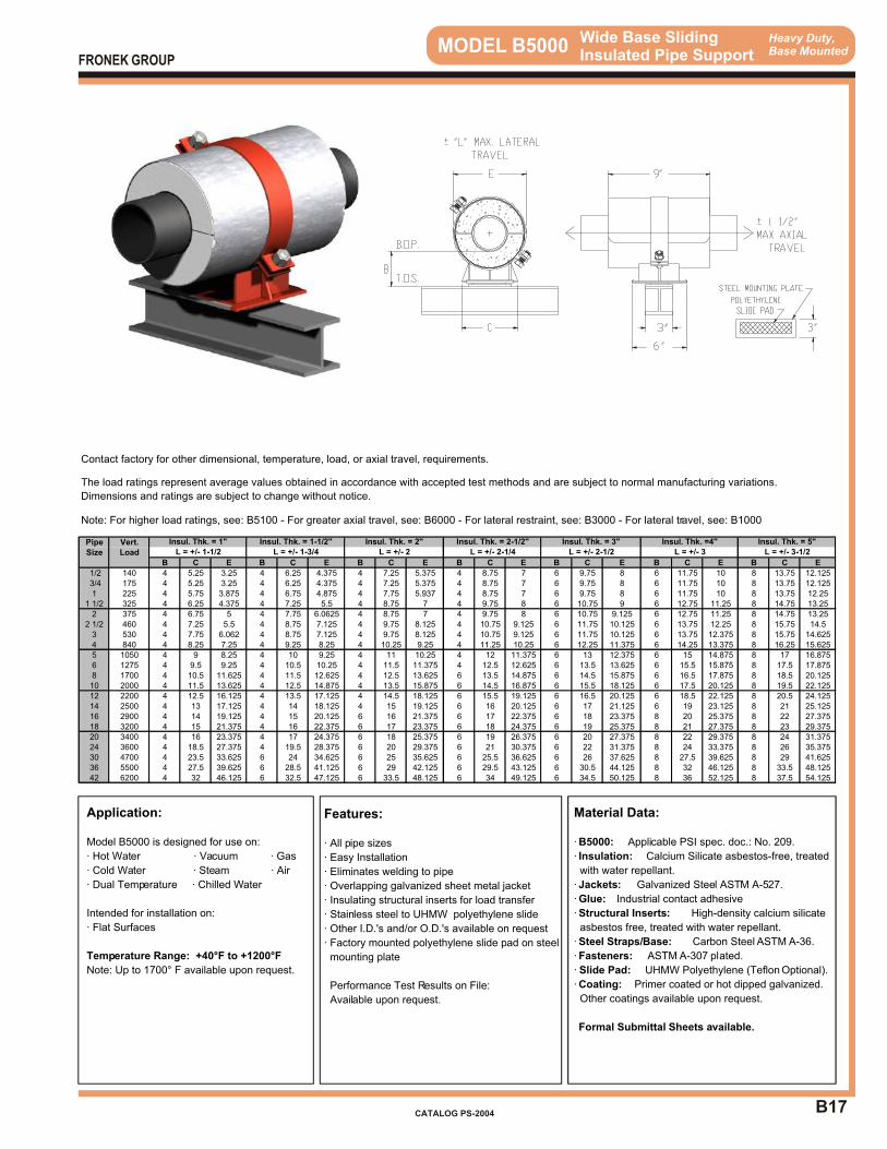
B17
Heavy Duty,Base Mounted MODEL B5000 Wide Base Sliding
Insulated Pipe Support
Application:
Model B5000 is designed for use on:
· Hot Water · Vacuum · Gas
· Cold Water · Steam · Air
· Dual Temperature · Chilled Water
Intended for installation on:
· Flat Surfaces
Temperature Range: +40°F to +1200°F
Note: Up to 1700° F available upon request.
Features:
· All pipe sizes
· Easy Installation
· Eliminates welding to pipe
· Overlapping galvanized sheet metal jacket
· Insulating structural inserts for load transfer
· Stainless steel to UHMW polyethylene slide
· Other I.D.'s and/or O.D.'s available on request
· Factory mounted polyethylene slide pad on steel
mounting plate
Performance Test Results on File:
Available upon request.
Material Data:
· B5000: Applicable PSI spec. doc.: No. 209.
· Insulation: Calcium Silicate asbestos-free, treated
with water repellant.
· Jackets: Galvanized Steel ASTM A-527.
· Glue: Industrial contact adhesive
· Structural Inserts: High-density calcium silicate
asbestos free, treated with water repellant.
· Steel Straps/Base: Carbon Steel ASTM A-36.
· Fasteners: ASTM A-307 plated.
· Slide Pad: UHMW Polyethylene (Teflon Optional).
· Coating: Primer coated or hot dipped galvanized.
Other coatings available upon request.
Formal Submittal Sheets available.
FRONEK GROUP
CATALOG PS-2004
Contact factory for other dimensional, temperature, load, or axial travel, requirements.
The load ratings represent average values obtained in accordance with accepted test methods and are subject to normal manufacturing variations.
Dimensions and ratings are subject to change without notice.
Note: For higher load ratings, see: B5100 - For greater axial travel, see: B6000 - For lateral restraint, see: B3000 - For lateral travel, see: B1000
Pipe Vert.Size Load
B C E B C E B C E B C E B C E B C E B C E
1/2 140 4 5.25 3.25 4 6.25 4.375 4 7.25 5.375 4 8.75 7 6 9.75 8 6 11.75 10 8 13.75 12.125 3/4 175 4 5.25 3.25 4 6.25 4.375 4 7.25 5.375 4 8.75 7 6 9.75 8 6 11.75 10 8 13.75 12.1251 225 4 5.75 3.875 4 6.75 4.875 4 7.75 5.937 4 8.75 7 6 9.75 8 6 11.75 10 8 13.75 12.25
1 1/2 325 4 6.25 4.375 4 7.25 5.5 4 8.75 7 4 9.75 8 6 10.75 9 6 12.75 11.25 8 14.75 13.252 375 4 6.75 5 4 7.75 6.0625 4 8.75 7 4 9.75 8 6 10.75 9.125 6 12.75 11.25 8 14.75 13.25
2 1/2 460 4 7.25 5.5 4 8.75 7.125 4 9.75 8.125 4 10.75 9.125 6 11.75 10.125 6 13.75 12.25 8 15.75 14.53 530 4 7.75 6.062 4 8.75 7.125 4 9.75 8.125 4 10.75 9.125 6 11.75 10.125 6 13.75 12.375 8 15.75 14.6254 840 4 8.25 7.25 4 9.25 8.25 4 10.25 9.25 4 11.25 10.25 6 12.25 11.375 6 14.25 13.375 8 16.25 15.6255 1050 4 9 8.25 4 10 9.25 4 11 10.25 4 12 11.375 6 13 12.375 6 15 14.875 8 17 16.8756 1275 4 9.5 9.25 4 10.5 10.25 4 11.5 11.375 4 12.5 12.625 6 13.5 13.625 6 15.5 15.875 8 17.5 17.8758 1700 4 10.5 11.625 4 11.5 12.625 4 12.5 13.625 6 13.5 14.875 6 14.5 15.875 6 16.5 17.875 8 18.5 20.12510 2000 4 11.5 13.625 4 12.5 14.875 4 13.5 15.875 6 14.5 16.875 6 15.5 18.125 6 17.5 20.125 8 19.5 22.12512 2200 4 12.5 16.125 4 13.5 17.125 4 14.5 18.125 6 15.5 19.125 6 16.5 20.125 6 18.5 22.125 8 20.5 24.12514 2500 4 13 17.125 4 14 18.125 4 15 19.125 6 16 20.125 6 17 21.125 6 19 23.125 8 21 25.12516 2900 4 14 19.125 4 15 20.125 6 16 21.375 6 17 22.375 6 18 23.375 8 20 25.375 8 22 27.37518 3200 4 15 21.375 4 16 22.375 6 17 23.375 6 18 24.375 6 19 25.375 8 21 27.375 8 23 29.37520 3400 4 16 23.375 4 17 24.375 6 18 25.375 6 19 26.375 6 20 27.375 8 22 29.375 8 24 31.37524 3600 4 18.5 27.375 4 19.5 28.375 6 20 29.375 6 21 30.375 6 22 31.375 8 24 33.375 8 26 35.37530 4700 4 23.5 33.625 6 24 34.625 6 25 35.625 6 25.5 36.625 6 26 37.625 8 27.5 39.625 8 29 41.62536 5500 4 27.5 39.625 6 28.5 41.125 6 29 42.125 6 29.5 43.125 6 30.5 44.125 8 32 46.125 8 33.5 48.12542 6200 4 32 46.125 6 32.5 47.125 6 33.5 48.125 6 34 49.125 6 34.5 50.125 8 36 52.125 8 37.5 54.125
Insul. Thk. = 1" Insul. Thk. = 1-1/2" Insul. Thk. = 2" Insul. Thk. = 2-1/2" Insul. Thk. = 3" Insul. Thk. =4" Insul. Thk. = 5"L = +/- 1-1/2 L = +/- 1-3/4 L = +/- 2 L = +/- 2-1/4 L = +/- 2-1/2 L = +/- 3 L = +/- 3-1/2

B18
Heavy Duty,Base Mounted MODEL B5100 Wide Base Sliding
Insulated Pipe Support
Application:
Model B5100 is designed for use on:
· Hot Water · Vacuum · Gas
· Cold Water · Steam · Air
· Dual Temperature · Chilled Water
Intended for installation on:
· Flat Surfaces
Temperature Range: +40°F to +1200°F
Note: Up to 1700° F available upon request.
Features:
· All pipe sizes
· Easy Installation
· Eliminates welding to pipe
· Overlapping galvanized sheet metal jacket
· Insulating structural inserts for load transfer
· Stainless steel to UHMW polyethylene slide
· Other I.D.'s and/or O.D.'s available on request
· Factory mounted polyethylene slide pad on steel
mounting plate
Performance Test Results on File:
Available upon request.
Material Data:
· B5100: Applicable PSI spec. doc.: No. 209.
· Insulation: Calcium Silicate asbestos-free, treated
with water repellant.
· Jackets: Galvanized Steel ASTM A-527.
· Glue: Industrial contact adhesive
· Structural Inserts: High-density calcium silicate
asbestos free, treated with water repellant.
· Steel Straps/Base: Carbon Steel ASTM A-36.
· Fasteners: ASTM A-307 plated.
· Slide Pad: UHMW Polyethylene (Teflon Optional).
· Coating: Primer coated or hot dipped galvanized.
Other coatings available upon request.
Formal Submittal Sheets available.
FRONEK GROUP
CATALOG PS-2004
Contact factory for other dimensional, temperature, load, or axial travel, requirements.
The load ratings represent average values obtained in accordance with accepted test methods and are subject to normal manufacturing variations.
Dimensions and ratings are subject to change without notice.
Note: For higher load ratings, see: B5200 - For greater axial travel, see: B6100 - For lateral restraint, see: B3100 - For lateral travel, see: B1100
Pipe Vert.Size Load
B C E B C E B C E B C E B C E B C E B C E
1/2 280 4 5.25 3.25 4 6.25 4.375 4 7.25 5.375 4 8.75 7 6 9.75 8 6 11.75 10 8 13.75 12.125 3/4 350 4 5.25 3.25 4 6.25 4.375 4 7.25 5.375 4 8.75 7 6 9.75 8 6 11.75 10 8 13.75 12.251 450 4 5.75 3.875 4 6.75 5 4 7.75 6.062 4 8.75 7 6 9.75 8 6 11.75 10 8 13.75 12.25
1 1/2 650 4 6.25 4.5 4 7.25 5.5 4 8.75 7.125 4 9.75 8.125 6 10.75 9.125 6 12.75 11.25 8 14.75 13.252 750 4 6.75 5 4 7.75 6.0625 4 8.75 7.125 4 9.75 8.125 6 10.75 9.125 6 12.75 11.25 8 14.75 13.25
2 1/2 920 4 7.25 5.5 4 8.75 7.125 4 9.75 8.125 4 10.75 9.125 6 11.75 10.125 6 13.75 12.25 8 15.75 14.53 1060 4 7.75 6.187 4 8.75 7.125 4 9.75 8.125 4 10.75 9.125 6 11.75 10.125 6 13.75 12.375 8 15.75 14.6254 1680 4 8.25 7.25 4 9.25 8.25 4 10.25 9.25 4 11.25 10.25 6 12.25 11.375 6 14.25 13.375 8 16.25 15.6255 2100 4 9 8.5 4 10 9.5 4 11 10.5 4 12 11.625 6 13 12.625 6 15 14.875 8 17 16.8756 2550 4 9.5 9.5 4 10.5 10.5 4 11.5 11.625 4 12.5 12.625 6 13.5 13.625 6 15.5 15.875 8 17.5 17.8758 3400 4 10.5 11.625 4 11.5 12.625 4 12.5 13.625 6 13.5 14.875 6 14.5 15.875 6 16.5 18.125 8 18.5 20.12510 4000 4 11.5 13.875 4 12.5 15.125 4 13.5 16.125 6 14.5 17.125 6 15.5 18.125 6 17.5 20.125 8 19.5 22.12512 4400 4 12.5 16.125 4 13.5 17.125 4 14.5 18.125 6 15.5 19.125 6 16.5 20.125 6 18.5 22.125 8 20.5 24.12514 5000 4 13 17.125 4 14 18.125 4 15 19.125 6 16 20.125 6 17 21.125 6 19 23.125 8 21 25.12516 5800 4 14 19.375 4 15 20.375 6 16 21.375 6 17 22.375 6 18 23.375 8 20 25.375 8 22 27.37518 6400 4 15 21.375 4 16 22.375 6 17 23.375 6 18 24.375 6 19 25.375 8 21 27.375 8 23 29.37520 6800 4 16 23.375 4 17 24.375 6 18 25.375 6 19 26.375 6 20 27.375 8 22 29.375 8 24 31.37524 7200 4 18.5 27.375 4 19.5 28.375 6 20 29.375 6 21 30.375 6 22 31.375 8 24 33.375 8 26 35.37530 9400 4 23.5 33.625 6 24 34.625 6 25 35.625 6 25.5 36.625 6 26 37.625 8 27.5 39.625 8 29 41.62536 11000 4 27.5 40.125 6 28.5 41.125 6 29 42.125 6 29.5 43.125 6 30.5 44.125 8 32 46.125 8 33.5 48.12542 12400 4 32 46.125 6 32.5 47.125 6 33.5 48.125 6 34 49.125 6 34.5 50.125 8 36 52.125 8 37.5 54.125
Insul. Thk. = 1" Insul. Thk. = 1-1/2" Insul. Thk. = 2" Insul. Thk. = 2-1/2" Insul. Thk. = 3" Insul. Thk. =4" Insul. Thk. = 5"L = +/- 1-1/2 L = +/- 1-3/4 L = +/- 2 L = +/- 2-1/4 L = +/- 2-1/2 L = +/- 3 L = +/- 3-1/2

B19
Heavy Duty,Base Mounted MODEL B5200 Wide Base Sliding
Insulated Pipe Support
Application:
Model B5200 is designed for use on:
· Hot Water · Vacuum · Gas
· Cold Water · Steam · Air
· Dual Temperature · Chilled Water
Intended for installation on:
· Flat Surfaces
Temperature Range: +40°F to +1200°F
Note: Up to 1700° F available upon request.
Features:
· All pipe sizes
· Easy Installation
· Eliminates welding to pipe
· Overlapping galvanized sheet metal jacket
· Insulating structural inserts for load transfer
· Stainless steel to UHMW polyethylene slide
· Other I.D.'s and/or O.D.'s available on request
· Factory mounted polyethylene slide pad on steel
mounting plate
Performance Test Results on File:
Available upon request.
Material Data:
· B5200: Applicable PSI spec. doc.: No. 209.
· Insulation: Calcium Silicate asbestos-free, treated
with water repellant.
· Jackets: Galvanized Steel ASTM A-527.
· Glue: Industrial contact adhesive
· Structural Inserts: High-density calcium silicate
asbestos free, treated with water repellant.
· Steel Straps/Base: Carbon Steel ASTM A-36.
· Fasteners: ASTM A-307 plated.
· Slide Pad: UHMW Polyethylene (Teflon Optional).
· Coating: Primer coated or hot dipped galvanized.
Other coatings available upon request.
Formal Submittal Sheets available.
FRONEK GROUP
CATALOG PS-2004
Contact factory for other dimensional, temperature, load, or axial travel, requirements.
The load ratings represent average values obtained in accordance with accepted test methods and are subject to normal manufacturing variations.
Dimensions and ratings are subject to change without notice.
Note: For higher load ratings, see: B5300 - For greater axial travel, see: B6200 - For lateral restraint, see: B3200 - For lateral travel, see: B1200
Pipe Vert.Size Load
B C E B C E B C E B C E B C E B C E B C E
1/2 400 4 5.25 3.25 4 6.25 4.375 4 7.25 5.375 4 8.75 7 6 9.75 8 6 11.75 10 8 13.75 12.125 3/4 500 4 5.25 3.25 4 6.25 4.375 4 7.25 5.375 4 8.75 7 6 9.75 8 6 11.75 10 8 13.75 12.251 650 4 5.75 4 4 6.75 5 4 7.75 6.062 4 8.75 7.125 6 9.75 8.125 6 11.75 10.125 8 13.75 12.25
1 1/2 950 4 6.25 4.5 4 7.25 5.5 4 8.75 7.125 4 9.75 8.125 6 10.75 9.125 6 12.75 11.25 8 14.75 13.252 1100 4 6.75 5 4 7.75 6.1875 4 8.75 7.125 4 9.75 8.125 6 10.75 9.125 6 12.75 11.25 8 14.75 13.25
2 1/2 1350 4 7.25 5.5 4 8.75 7.125 4 9.75 8.125 4 10.75 9.125 6 11.75 10.125 6 13.75 12.25 8 15.75 14.53 1600 4 7.75 6.187 4 8.75 7.125 4 9.75 8.125 4 10.75 9.125 6 11.75 10.125 6 13.75 12.375 8 15.75 14.6254 2500 4 8.25 7.25 4 9.25 8.25 4 10.25 9.25 4 11.25 10.25 6 12.25 11.375 6 14.25 13.375 8 16.25 15.6255 3100 4 9 8.5 4 10 9.5 4 11 10.5 4 12 11.625 6 13 12.625 6 15 14.875 8 17 16.8756 3800 4 9.5 9.5 4 10.5 10.5 4 11.5 11.625 4 12.5 12.625 6 13.5 13.625 6 15.5 15.875 8 17.5 17.8758 5100 4 10.5 11.625 4 11.5 12.625 4 12.5 13.625 6 13.5 14.875 6 14.5 15.875 6 16.5 18.125 8 18.5 20.12510 6000 4 11.5 13.875 4 12.5 15.125 4 13.5 16.125 6 14.5 17.125 6 15.5 18.125 6 17.5 20.125 8 19.5 22.12512 6600 4 12.5 16.125 4 13.5 17.125 4 14.5 18.125 6 15.5 19.125 6 16.5 20.125 6 18.5 22.125 8 20.5 24.12514 7500 4 13 17.125 4 14 18.125 4 15 19.125 6 16 20.125 6 17 21.125 6 19 23.125 8 21 25.12516 8700 4 14 19.375 4 15 20.375 6 16 21.375 6 17 22.375 6 18 23.375 8 20 25.375 8 22 27.37518 9600 4 15 21.375 4 16 22.375 6 17 23.375 6 18 24.375 6 19 25.375 8 21 27.375 8 23 29.37520 10200 4 16 23.375 4 17 24.375 6 18 25.375 6 19 26.375 6 20 27.375 8 22 29.375 8 24 31.37524 10800 4 18.5 27.375 4 19.5 28.375 6 20 29.375 6 21 30.375 6 22 31.375 8 24 33.375 8 26 35.37530 14100 4 23.5 33.625 6 24 34.625 6 25 35.625 6 25.5 36.625 6 26 37.625 8 27.5 39.625 8 29 41.62536 16500 4 27.5 40.125 6 28.5 41.125 6 29 42.125 6 29.5 43.125 6 30.5 44.125 8 32 46.125 8 33.5 48.12542 18600 4 32 46.125 6 32.5 47.125 6 33.5 48.125 6 34 49.125 6 34.5 50.125 8 36 52.125 8 37.5 54.125
Insul. Thk. = 1" Insul. Thk. = 1-1/2" Insul. Thk. = 2" Insul. Thk. = 2-1/2" Insul. Thk. = 3" Insul. Thk. =4" Insul. Thk. = 5"L = +/- 1-1/2 L = +/- 1-3/4 L = +/- 2 L = +/- 2-1/4 L = +/- 2-1/2 L = +/- 3 L = +/- 3-1/2
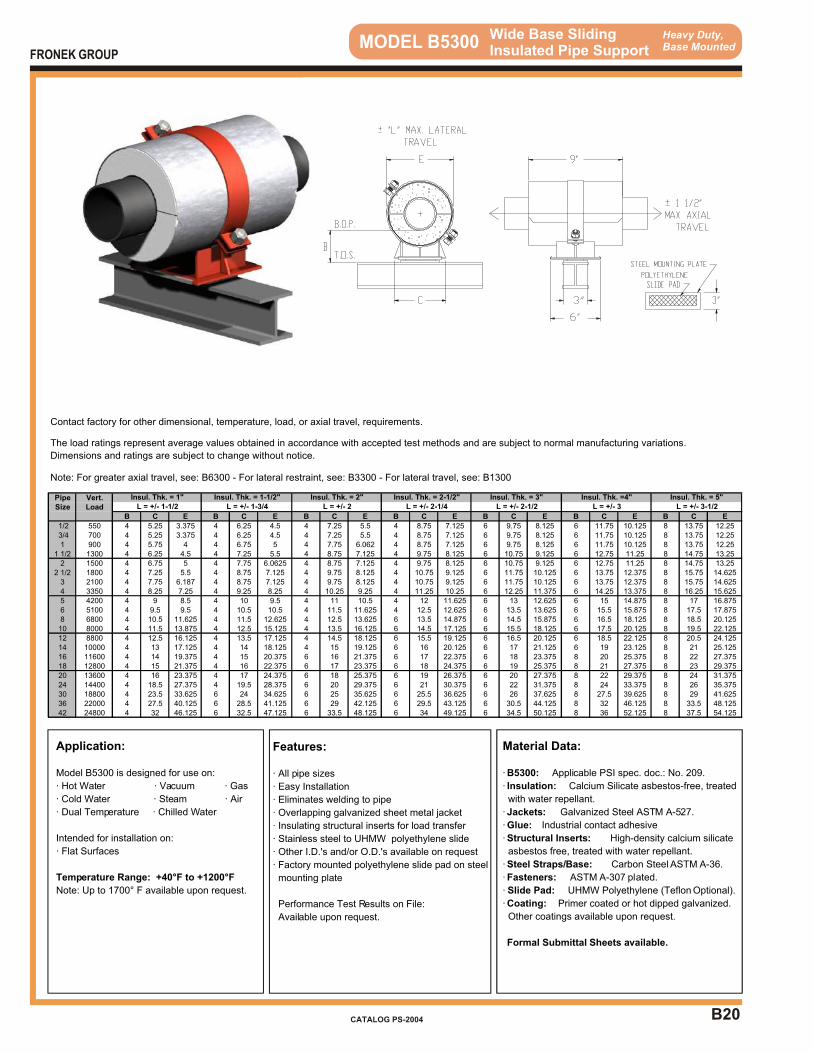
B20
Heavy Duty,Base Mounted MODEL B5300 Wide Base Sliding
Insulated Pipe Support
Application:
Model B5300 is designed for use on:
· Hot Water · Vacuum · Gas
· Cold Water · Steam · Air
· Dual Temperature · Chilled Water
Intended for installation on:
· Flat Surfaces
Temperature Range: +40°F to +1200°F
Note: Up to 1700° F available upon request.
Features:
· All pipe sizes
· Easy Installation
· Eliminates welding to pipe
· Overlapping galvanized sheet metal jacket
· Insulating structural inserts for load transfer
· Stainless steel to UHMW polyethylene slide
· Other I.D.'s and/or O.D.'s available on request
· Factory mounted polyethylene slide pad on steel
mounting plate
Performance Test Results on File:
Available upon request.
Material Data:
· B5300: Applicable PSI spec. doc.: No. 209.
· Insulation: Calcium Silicate asbestos-free, treated
with water repellant.
· Jackets: Galvanized Steel ASTM A-527.
· Glue: Industrial contact adhesive
· Structural Inserts: High-density calcium silicate
asbestos free, treated with water repellant.
· Steel Straps/Base: Carbon Steel ASTM A-36.
· Fasteners: ASTM A-307 plated.
· Slide Pad: UHMW Polyethylene (Teflon Optional).
· Coating: Primer coated or hot dipped galvanized.
Other coatings available upon request.
Formal Submittal Sheets available.
FRONEK GROUP
CATALOG PS-2004
Contact factory for other dimensional, temperature, load, or axial travel, requirements.
The load ratings represent average values obtained in accordance with accepted test methods and are subject to normal manufacturing variations.
Dimensions and ratings are subject to change without notice.
Note: For greater axial travel, see: B6300 - For lateral restraint, see: B3300 - For lateral travel, see: B1300
Pipe Vert.Size Load
B C E B C E B C E B C E B C E B C E B C E
1/2 550 4 5.25 3.375 4 6.25 4.5 4 7.25 5.5 4 8.75 7.125 6 9.75 8.125 6 11.75 10.125 8 13.75 12.25 3/4 700 4 5.25 3.375 4 6.25 4.5 4 7.25 5.5 4 8.75 7.125 6 9.75 8.125 6 11.75 10.125 8 13.75 12.251 900 4 5.75 4 4 6.75 5 4 7.75 6.062 4 8.75 7.125 6 9.75 8.125 6 11.75 10.125 8 13.75 12.25
1 1/2 1300 4 6.25 4.5 4 7.25 5.5 4 8.75 7.125 4 9.75 8.125 6 10.75 9.125 6 12.75 11.25 8 14.75 13.252 1500 4 6.75 5 4 7.75 6.0625 4 8.75 7.125 4 9.75 8.125 6 10.75 9.125 6 12.75 11.25 8 14.75 13.25
2 1/2 1800 4 7.25 5.5 4 8.75 7.125 4 9.75 8.125 4 10.75 9.125 6 11.75 10.125 6 13.75 12.375 8 15.75 14.6253 2100 4 7.75 6.187 4 8.75 7.125 4 9.75 8.125 4 10.75 9.125 6 11.75 10.125 6 13.75 12.375 8 15.75 14.6254 3350 4 8.25 7.25 4 9.25 8.25 4 10.25 9.25 4 11.25 10.25 6 12.25 11.375 6 14.25 13.375 8 16.25 15.6255 4200 4 9 8.5 4 10 9.5 4 11 10.5 4 12 11.625 6 13 12.625 6 15 14.875 8 17 16.8756 5100 4 9.5 9.5 4 10.5 10.5 4 11.5 11.625 4 12.5 12.625 6 13.5 13.625 6 15.5 15.875 8 17.5 17.8758 6800 4 10.5 11.625 4 11.5 12.625 4 12.5 13.625 6 13.5 14.875 6 14.5 15.875 6 16.5 18.125 8 18.5 20.12510 8000 4 11.5 13.875 4 12.5 15.125 4 13.5 16.125 6 14.5 17.125 6 15.5 18.125 6 17.5 20.125 8 19.5 22.12512 8800 4 12.5 16.125 4 13.5 17.125 4 14.5 18.125 6 15.5 19.125 6 16.5 20.125 6 18.5 22.125 8 20.5 24.12514 10000 4 13 17.125 4 14 18.125 4 15 19.125 6 16 20.125 6 17 21.125 6 19 23.125 8 21 25.12516 11600 4 14 19.375 4 15 20.375 6 16 21.375 6 17 22.375 6 18 23.375 8 20 25.375 8 22 27.37518 12800 4 15 21.375 4 16 22.375 6 17 23.375 6 18 24.375 6 19 25.375 8 21 27.375 8 23 29.37520 13600 4 16 23.375 4 17 24.375 6 18 25.375 6 19 26.375 6 20 27.375 8 22 29.375 8 24 31.37524 14400 4 18.5 27.375 4 19.5 28.375 6 20 29.375 6 21 30.375 6 22 31.375 8 24 33.375 8 26 35.37530 18800 4 23.5 33.625 6 24 34.625 6 25 35.625 6 25.5 36.625 6 26 37.625 8 27.5 39.625 8 29 41.62536 22000 4 27.5 40.125 6 28.5 41.125 6 29 42.125 6 29.5 43.125 6 30.5 44.125 8 32 46.125 8 33.5 48.12542 24800 4 32 46.125 6 32.5 47.125 6 33.5 48.125 6 34 49.125 6 34.5 50.125 8 36 52.125 8 37.5 54.125
Insul. Thk. = 1" Insul. Thk. = 1-1/2" Insul. Thk. = 2" Insul. Thk. = 2-1/2" Insul. Thk. = 3" Insul. Thk. =4" Insul. Thk. = 5"L = +/- 1-1/2 L = +/- 1-3/4 L = +/- 2 L = +/- 2-1/4 L = +/- 2-1/2 L = +/- 3 L = +/- 3-1/2
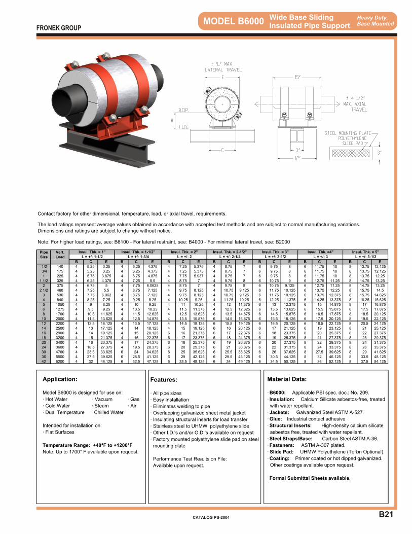
B21
Heavy Duty,Base Mounted MODEL B6000 Wide Base Sliding
Insulated Pipe Support
Application:
Model B6000 is designed for use on:
· Hot Water · Vacuum · Gas
· Cold Water · Steam · Air
· Dual Temperature · Chilled Water
Intended for installation on:
· Flat Surfaces
Temperature Range: +40°F to +1200°F
Note: Up to 1700° F available upon request.
Features:
· All pipe sizes
· Easy Installation
· Eliminates welding to pipe
· Overlapping galvanized sheet metal jacket
· Insulating structural inserts for load transfer
· Stainless steel to UHMW polyethylene slide
· Other I.D.'s and/or O.D.'s available on request
· Factory mounted polyethylene slide pad on steel
mounting plate
Performance Test Results on File:
Available upon request.
Material Data:
· B6000: Applicable PSI spec. doc.: No. 209.
· Insulation: Calcium Silicate asbestos-free, treated
with water repellant.
· Jackets: Galvanized Steel ASTM A-527.
· Glue: Industrial contact adhesive
· Structural Inserts: High-density calcium silicate
asbestos free, treated with water repellant.
· Steel Straps/Base: Carbon Steel ASTM A-36.
· Fasteners: ASTM A-307 plated.
· Slide Pad: UHMW Polyethylene (Teflon Optional).
· Coating: Primer coated or hot dipped galvanized.
Other coatings available upon request.
Formal Submittal Sheets available.
FRONEK GROUP
CATALOG PS-2004
Contact factory for other dimensional, temperature, load, or axial travel, requirements.
The load ratings represent average values obtained in accordance with accepted test methods and are subject to normal manufacturing variations.
Dimensions and ratings are subject to change without notice.
Note: For higher load ratings, see: B6100 - For lateral restraint, see: B4000 - For minimal lateral travel, see: B2000
Pipe Vert.Size Load
B C E B C E B C E B C E B C E B C E B C E
1/2 140 4 5.25 3.25 4 6.25 4.375 4 7.25 5.375 4 8.75 7 6 9.75 8 6 11.75 10 8 13.75 12.125 3/4 175 4 5.25 3.25 4 6.25 4.375 4 7.25 5.375 4 8.75 7 6 9.75 8 6 11.75 10 8 13.75 12.1251 225 4 5.75 3.875 4 6.75 4.875 4 7.75 5.937 4 8.75 7 6 9.75 8 6 11.75 10 8 13.75 12.25
1 1/2 325 4 6.25 4.375 4 7.25 5.5 4 8.75 7 4 9.75 8 6 10.75 9 6 12.75 11.25 8 14.75 13.252 375 4 6.75 5 4 7.75 6.0625 4 8.75 7 4 9.75 8 6 10.75 9.125 6 12.75 11.25 8 14.75 13.25
2 1/2 460 4 7.25 5.5 4 8.75 7.125 4 9.75 8.125 4 10.75 9.125 6 11.75 10.125 6 13.75 12.25 8 15.75 14.53 530 4 7.75 6.062 4 8.75 7.125 4 9.75 8.125 4 10.75 9.125 6 11.75 10.125 6 13.75 12.375 8 15.75 14.6254 840 4 8.25 7.25 4 9.25 8.25 4 10.25 9.25 4 11.25 10.25 6 12.25 11.375 6 14.25 13.375 8 16.25 15.6255 1050 4 9 8.25 4 10 9.25 4 11 10.25 4 12 11.375 6 13 12.375 6 15 14.875 8 17 16.8756 1275 4 9.5 9.25 4 10.5 10.25 4 11.5 11.375 4 12.5 12.625 6 13.5 13.625 6 15.5 15.875 8 17.5 17.8758 1700 4 10.5 11.625 4 11.5 12.625 4 12.5 13.625 6 13.5 14.875 6 14.5 15.875 6 16.5 17.875 8 18.5 20.12510 2000 4 11.5 13.625 4 12.5 14.875 4 13.5 15.875 6 14.5 16.875 6 15.5 18.125 6 17.5 20.125 8 19.5 22.12512 2200 4 12.5 16.125 4 13.5 17.125 4 14.5 18.125 6 15.5 19.125 6 16.5 20.125 6 18.5 22.125 8 20.5 24.12514 2500 4 13 17.125 4 14 18.125 4 15 19.125 6 16 20.125 6 17 21.125 6 19 23.125 8 21 25.12516 2900 4 14 19.125 4 15 20.125 6 16 21.375 6 17 22.375 6 18 23.375 8 20 25.375 8 22 27.37518 3200 4 15 21.375 4 16 22.375 6 17 23.375 6 18 24.375 6 19 25.375 8 21 27.375 8 23 29.37520 3400 4 16 23.375 4 17 24.375 6 18 25.375 6 19 26.375 6 20 27.375 8 22 29.375 8 24 31.37524 3600 4 18.5 27.375 4 19.5 28.375 6 20 29.375 6 21 30.375 6 22 31.375 8 24 33.375 8 26 35.37530 4700 4 23.5 33.625 6 24 34.625 6 25 35.625 6 25.5 36.625 6 26 37.625 8 27.5 39.625 8 29 41.62536 5500 4 27.5 39.625 6 28.5 41.125 6 29 42.125 6 29.5 43.125 6 30.5 44.125 8 32 46.125 8 33.5 48.12542 6200 4 32 46.125 6 32.5 47.125 6 33.5 48.125 6 34 49.125 6 34.5 50.125 8 36 52.125 8 37.5 54.125
Insul. Thk. = 3" Insul. Thk. =4" Insul. Thk. = 5"L = +/- 1-1/2 L = +/- 1-3/4 L = +/- 2 L = +/- 2-1/4 L = +/- 2-1/2 L = +/- 3 L = +/- 3-1/2
Insul. Thk. = 1" Insul. Thk. = 1-1/2" Insul. Thk. = 2" Insul. Thk. = 2-1/2"
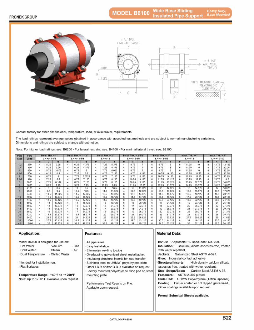
B22
Heavy Duty,Base Mounted MODEL B6100 Wide Base Sliding
Insulated Pipe Support
Application:
Model B6100 is designed for use on:
· Hot Water · Vacuum · Gas
· Cold Water · Steam · Air
· Dual Temperature · Chilled Water
Intended for installation on:
· Flat Surfaces
Temperature Range: +40°F to +1200°F
Note: Up to 1700° F available upon request.
Features:
· All pipe sizes
· Easy Installation
· Eliminates welding to pipe
· Overlapping galvanized sheet metal jacket
· Insulating structural inserts for load transfer
· Stainless steel to UHMW polyethylene slide
· Other I.D.'s and/or O.D.'s available on request
· Factory mounted polyethylene slide pad on steel
mounting plate
Performance Test Results on File:
Available upon request.
Material Data:
· B6100: Applicable PSI spec. doc.: No. 209.
· Insulation: Calcium Silicate asbestos-free, treated
with water repellant.
· Jackets: Galvanized Steel ASTM A-527.
· Glue: Industrial contact adhesive
· Structural Inserts: High-density calcium silicate
asbestos free, treated with water repellant.
· Steel Straps/Base: Carbon Steel ASTM A-36.
· Fasteners: ASTM A-307 plated.
· Slide Pad: UHMW Polyethylene (Teflon Optional).
· Coating: Primer coated or hot dipped galvanized.
Other coatings available upon request.
Formal Submittal Sheets available.
FRONEK GROUP
CATALOG PS-2004
Contact factory for other dimensional, temperature, load, or axial travel, requirements.
The load ratings represent average values obtained in accordance with accepted test methods and are subject to normal manufacturing variations.
Dimensions and ratings are subject to change without notice.
Note: For higher load ratings, see: B6200 - For lateral restraint, see: B4100 - For minimal lateral travel, see: B2100
Pipe Vert.Size Load
B C E B C E B C E B C E B C E B C E B C E
1/2 280 4 5.25 3.25 4 6.25 4.375 4 7.25 5.375 4 8.75 7 6 9.75 8 6 11.75 10 8 13.75 12.125 3/4 350 4 5.25 3.25 4 6.25 4.375 4 7.25 5.375 4 8.75 7 6 9.75 8 6 11.75 10 8 13.75 12.251 450 4 5.75 3.875 4 6.75 5 4 7.75 6.062 4 8.75 7 6 9.75 8 6 11.75 10 8 13.75 12.25
1 1/2 650 4 6.25 4.5 4 7.25 5.5 4 8.75 7.125 4 9.75 8.125 6 10.75 9.125 6 12.75 11.25 8 14.75 13.252 750 4 6.75 5 4 7.75 6.0625 4 8.75 7.125 4 9.75 8.125 6 10.75 9.125 6 12.75 11.25 8 14.75 13.25
2 1/2 920 4 7.25 5.5 4 8.75 7.125 4 9.75 8.125 4 10.75 9.125 6 11.75 10.125 6 13.75 12.25 8 15.75 14.53 1060 4 7.75 6.187 4 8.75 7.125 4 9.75 8.125 4 10.75 9.125 6 11.75 10.125 6 13.75 12.375 8 15.75 14.6254 1680 4 8.25 7.25 4 9.25 8.25 4 10.25 9.25 4 11.25 10.25 6 12.25 11.375 6 14.25 13.375 8 16.25 15.6255 2100 4 9 8.5 4 10 9.5 4 11 10.5 4 12 11.625 6 13 12.625 6 15 14.875 8 17 16.8756 2550 4 9.5 9.5 4 10.5 10.5 4 11.5 11.625 4 12.5 12.625 6 13.5 13.625 6 15.5 15.875 8 17.5 17.8758 3400 4 10.5 11.625 4 11.5 12.625 4 12.5 13.625 6 13.5 14.875 6 14.5 15.875 6 16.5 18.125 8 18.5 20.12510 4000 4 11.5 13.875 4 12.5 15.125 4 13.5 16.125 6 14.5 17.125 6 15.5 18.125 6 17.5 20.125 8 19.5 22.12512 4400 4 12.5 16.125 4 13.5 17.125 4 14.5 18.125 6 15.5 19.125 6 16.5 20.125 6 18.5 22.125 8 20.5 24.12514 5000 4 13 17.125 4 14 18.125 4 15 19.125 6 16 20.125 6 17 21.125 6 19 23.125 8 21 25.12516 5800 4 14 19.375 4 15 20.375 6 16 21.375 6 17 22.375 6 18 23.375 8 20 25.375 8 22 27.37518 6400 4 15 21.375 4 16 22.375 6 17 23.375 6 18 24.375 6 19 25.375 8 21 27.375 8 23 29.37520 6800 4 16 23.375 4 17 24.375 6 18 25.375 6 19 26.375 6 20 27.375 8 22 29.375 8 24 31.37524 7200 4 18.5 27.375 4 19.5 28.375 6 20 29.375 6 21 30.375 6 22 31.375 8 24 33.375 8 26 35.37530 9400 4 23.5 33.625 6 24 34.625 6 25 35.625 6 25.5 36.625 6 26 37.625 8 27.5 39.625 8 29 41.62536 11000 4 27.5 40.125 6 28.5 41.125 6 29 42.125 6 29.5 43.125 6 30.5 44.125 8 32 46.125 8 33.5 48.12542 12400 4 32 46.125 6 32.5 47.125 6 33.5 48.125 6 34 49.125 6 34.5 50.125 8 36 52.125 8 37.5 54.125
Insul. Thk. = 3" Insul. Thk. =4" Insul. Thk. = 5"L = +/- 1-1/2 L = +/- 1-3/4 L = +/- 2 L = +/- 2-1/4 L = +/- 2-1/2 L = +/- 3 L = +/- 3-1/2
Insul. Thk. = 1" Insul. Thk. = 1-1/2" Insul. Thk. = 2" Insul. Thk. = 2-1/2"

B23
Heavy Duty,Base Mounted MODEL B6200 Wide Base Sliding
Insulated Pipe Support
Application:
Model B6200 is designed for use on:
· Hot Water · Vacuum · Gas
· Cold Water · Steam · Air
· Dual Temperature · Chilled Water
Intended for installation on:
· Flat Surfaces
Temperature Range: +40°F to +1200°F
Note: Up to 1700° F available upon request.
Features:
· All pipe sizes
· Easy Installation
· Eliminates welding to pipe
· Overlapping galvanized sheet metal jacket
· Insulating structural inserts for load transfer
· Stainless steel to UHMW polyethylene slide
· Other I.D.'s and/or O.D.'s available on request
· Factory mounted polyethylene slide pad on steel
mounting plate
Performance Test Results on File:
Available upon request.
Material Data:
· B6200: Applicable PSI spec. doc.: No. 209.
· Insulation: Calcium Silicate asbestos-free, treated
with water repellant.
· Jackets: Galvanized Steel ASTM A-527.
· Glue: Industrial contact adhesive
· Structural Inserts: High-density calcium silicate
asbestos free, treated with water repellant.
· Steel Straps/Base: Carbon Steel ASTM A-36.
· Fasteners: ASTM A-307 plated.
· Slide Pad: UHMW Polyethylene (Teflon Optional).
· Coating: Primer coated or hot dipped galvanized.
Other coatings available upon request.
Formal Submittal Sheets available.
FRONEK GROUP
CATALOG PS-2004
Contact factory for other dimensional, temperature, load, or axial travel, requirements.
The load ratings represent average values obtained in accordance with accepted test methods and are subject to normal manufacturing variations.
Dimensions and ratings are subject to change without notice.
Note: For higher load ratings, see: B6300 - For lateral restraint, see: B4200 - For minimal lateral travel, see: B2200
Pipe Vert.Size Load
B C E B C E B C E B C E B C E B C E B C E
1/2 400 4 5.25 3.25 4 6.25 4.375 4 7.25 5.375 4 8.75 7 6 9.75 8 6 11.75 10 8 13.75 12.125 3/4 500 4 5.25 3.25 4 6.25 4.375 4 7.25 5.375 4 8.75 7 6 9.75 8 6 11.75 10 8 13.75 12.251 650 4 5.75 4 4 6.75 5 4 7.75 6.062 4 8.75 7.125 6 9.75 8.125 6 11.75 10.125 8 13.75 12.25
1 1/2 950 4 6.25 4.5 4 7.25 5.5 4 8.75 7.125 4 9.75 8.125 6 10.75 9.125 6 12.75 11.25 8 14.75 13.252 1100 4 6.75 5 4 7.75 6.1875 4 8.75 7.125 4 9.75 8.125 6 10.75 9.125 6 12.75 11.25 8 14.75 13.25
2 1/2 1350 4 7.25 5.5 4 8.75 7.125 4 9.75 8.125 4 10.75 9.125 6 11.75 10.125 6 13.75 12.25 8 15.75 14.53 1600 4 7.75 6.187 4 8.75 7.125 4 9.75 8.125 4 10.75 9.125 6 11.75 10.125 6 13.75 12.375 8 15.75 14.6254 2500 4 8.25 7.25 4 9.25 8.25 4 10.25 9.25 4 11.25 10.25 6 12.25 11.375 6 14.25 13.375 8 16.25 15.6255 3100 4 9 8.5 4 10 9.5 4 11 10.5 4 12 11.625 6 13 12.625 6 15 14.875 8 17 16.8756 3800 4 9.5 9.5 4 10.5 10.5 4 11.5 11.625 4 12.5 12.625 6 13.5 13.625 6 15.5 15.875 8 17.5 17.8758 5100 4 10.5 11.625 4 11.5 12.625 4 12.5 13.625 6 13.5 14.875 6 14.5 15.875 6 16.5 18.125 8 18.5 20.12510 6000 4 11.5 13.875 4 12.5 15.125 4 13.5 16.125 6 14.5 17.125 6 15.5 18.125 6 17.5 20.125 8 19.5 22.12512 6600 4 12.5 16.125 4 13.5 17.125 4 14.5 18.125 6 15.5 19.125 6 16.5 20.125 6 18.5 22.125 8 20.5 24.12514 7500 4 13 17.125 4 14 18.125 4 15 19.125 6 16 20.125 6 17 21.125 6 19 23.125 8 21 25.12516 8700 4 14 19.375 4 15 20.375 6 16 21.375 6 17 22.375 6 18 23.375 8 20 25.375 8 22 27.37518 9600 4 15 21.375 4 16 22.375 6 17 23.375 6 18 24.375 6 19 25.375 8 21 27.375 8 23 29.37520 10200 4 16 23.375 4 17 24.375 6 18 25.375 6 19 26.375 6 20 27.375 8 22 29.375 8 24 31.37524 10800 4 18.5 27.375 4 19.5 28.375 6 20 29.375 6 21 30.375 6 22 31.375 8 24 33.375 8 26 35.37530 14100 4 23.5 33.625 6 24 34.625 6 25 35.625 6 25.5 36.625 6 26 37.625 8 27.5 39.625 8 29 41.62536 16500 4 27.5 40.125 6 28.5 41.125 6 29 42.125 6 29.5 43.125 6 30.5 44.125 8 32 46.125 8 33.5 48.12542 18600 4 32 46.125 6 32.5 47.125 6 33.5 48.125 6 34 49.125 6 34.5 50.125 8 36 52.125 8 37.5 54.125
Insul. Thk. = 3" Insul. Thk. =4" Insul. Thk. = 5"L = +/- 1-1/2 L = +/- 1-3/4 L = +/- 2 L = +/- 2-1/4 L = +/- 2-1/2 L = +/- 3 L = +/- 3-1/2
Insul. Thk. = 1" Insul. Thk. = 1-1/2" Insul. Thk. = 2" Insul. Thk. = 2-1/2"

B24
Heavy Duty,Base Mounted MODEL B6300 Wide Base Sliding
Insulated Pipe Support
Application:
Model B6300 is designed for use on:
· Hot Water · Vacuum · Gas
· Cold Water · Steam · Air
· Dual Temperature · Chilled Water
Intended for installation on:
· Flat Surfaces
Temperature Range: +40°F to +1200°F
Note: Up to 1700° F available upon request.
Features:
· All pipe sizes
· Easy Installation
· Eliminates welding to pipe
· Overlapping galvanized sheet metal jacket
· Insulating structural inserts for load transfer
· Stainless steel to UHMW polyethylene slide
· Other I.D.'s and/or O.D.'s available on request
· Factory mounted polyethylene slide pad on steel
mounting plate
Performance Test Results on File:
Available upon request.
Material Data:
· B6300: Applicable PSI spec. doc.: No. 209.
· Insulation: Calcium Silicate asbestos-free, treated
with water repellant.
· Jackets: Galvanized Steel ASTM A-527.
· Glue: Industrial contact adhesive
· Structural Inserts: High-density calcium silicate
asbestos free, treated with water repellant.
· Steel Straps/Base: Carbon Steel ASTM A-36.
· Fasteners: ASTM A-307 plated.
· Slide Pad: UHMW Polyethylene (Teflon Optional).
· Coating: Primer coated or hot dipped galvanized.
Other coatings available upon request.
Formal Submittal Sheets available.
FRONEK GROUP
CATALOG PS-2004
Contact factory for other dimensional, temperature, load, or axial travel, requirements.
The load ratings represent average values obtained in accordance with accepted test methods and are subject to normal manufacturing variations.
Dimensions and ratings are subject to change without notice.
Note: For lateral restraint, see: B4300 - For minimal lateral travel, see: B2300
Pipe Vert.Size Load
B C E B C E B C E B C E B C E B C E B C E
1/2 550 4 5.25 3.375 4 6.25 4.5 4 7.25 5.5 4 8.75 7.125 6 9.75 8.125 6 11.75 10.125 8 13.75 12.25 3/4 700 4 5.25 3.375 4 6.25 4.5 4 7.25 5.5 4 8.75 7.125 6 9.75 8.125 6 11.75 10.125 8 13.75 12.251 900 4 5.75 4 4 6.75 5 4 7.75 6.062 4 8.75 7.125 6 9.75 8.125 6 11.75 10.125 8 13.75 12.25
1 1/2 1300 4 6.25 4.5 4 7.25 5.5 4 8.75 7.125 4 9.75 8.125 6 10.75 9.125 6 12.75 11.25 8 14.75 13.252 1500 4 6.75 5 4 7.75 6.0625 4 8.75 7.125 4 9.75 8.125 6 10.75 9.125 6 12.75 11.25 8 14.75 13.25
2 1/2 1800 4 7.25 5.5 4 8.75 7.125 4 9.75 8.125 4 10.75 9.125 6 11.75 10.125 6 13.75 12.375 8 15.75 14.6253 2100 4 7.75 6.187 4 8.75 7.125 4 9.75 8.125 4 10.75 9.125 6 11.75 10.125 6 13.75 12.375 8 15.75 14.6254 3350 4 8.25 7.25 4 9.25 8.25 4 10.25 9.25 4 11.25 10.25 6 12.25 11.375 6 14.25 13.375 8 16.25 15.6255 4200 4 9 8.5 4 10 9.5 4 11 10.5 4 12 11.625 6 13 12.625 6 15 14.875 8 17 16.8756 5100 4 9.5 9.5 4 10.5 10.5 4 11.5 11.625 4 12.5 12.625 6 13.5 13.625 6 15.5 15.875 8 17.5 17.8758 6800 4 10.5 11.625 4 11.5 12.625 4 12.5 13.625 6 13.5 14.875 6 14.5 15.875 6 16.5 18.125 8 18.5 20.12510 8000 4 11.5 13.875 4 12.5 15.125 4 13.5 16.125 6 14.5 17.125 6 15.5 18.125 6 17.5 20.125 8 19.5 22.12512 8800 4 12.5 16.125 4 13.5 17.125 4 14.5 18.125 6 15.5 19.125 6 16.5 20.125 6 18.5 22.125 8 20.5 24.12514 10000 4 13 17.125 4 14 18.125 4 15 19.125 6 16 20.125 6 17 21.125 6 19 23.125 8 21 25.12516 11600 4 14 19.375 4 15 20.375 6 16 21.375 6 17 22.375 6 18 23.375 8 20 25.375 8 22 27.37518 12800 4 15 21.375 4 16 22.375 6 17 23.375 6 18 24.375 6 19 25.375 8 21 27.375 8 23 29.37520 13600 4 16 23.375 4 17 24.375 6 18 25.375 6 19 26.375 6 20 27.375 8 22 29.375 8 24 31.37524 14400 4 18.5 27.375 4 19.5 28.375 6 20 29.375 6 21 30.375 6 22 31.375 8 24 33.375 8 26 35.37530 18800 4 23.5 33.625 6 24 34.625 6 25 35.625 6 25.5 36.625 6 26 37.625 8 27.5 39.625 8 29 41.62536 22000 4 27.5 40.125 6 28.5 41.125 6 29 42.125 6 29.5 43.125 6 30.5 44.125 8 32 46.125 8 33.5 48.12542 24800 4 32 46.125 6 32.5 47.125 6 33.5 48.125 6 34 49.125 6 34.5 50.125 8 36 52.125 8 37.5 54.125
Insul. Thk. = 3" Insul. Thk. =4" Insul. Thk. = 5"L = +/- 1-1/2 L = +/- 1-3/4 L = +/- 2 L = +/- 2-1/4 L = +/- 2-1/2 L = +/- 3 L = +/- 3-1/2
Insul. Thk. = 1" Insul. Thk. = 1-1/2" Insul. Thk. = 2" Insul. Thk. = 2-1/2"
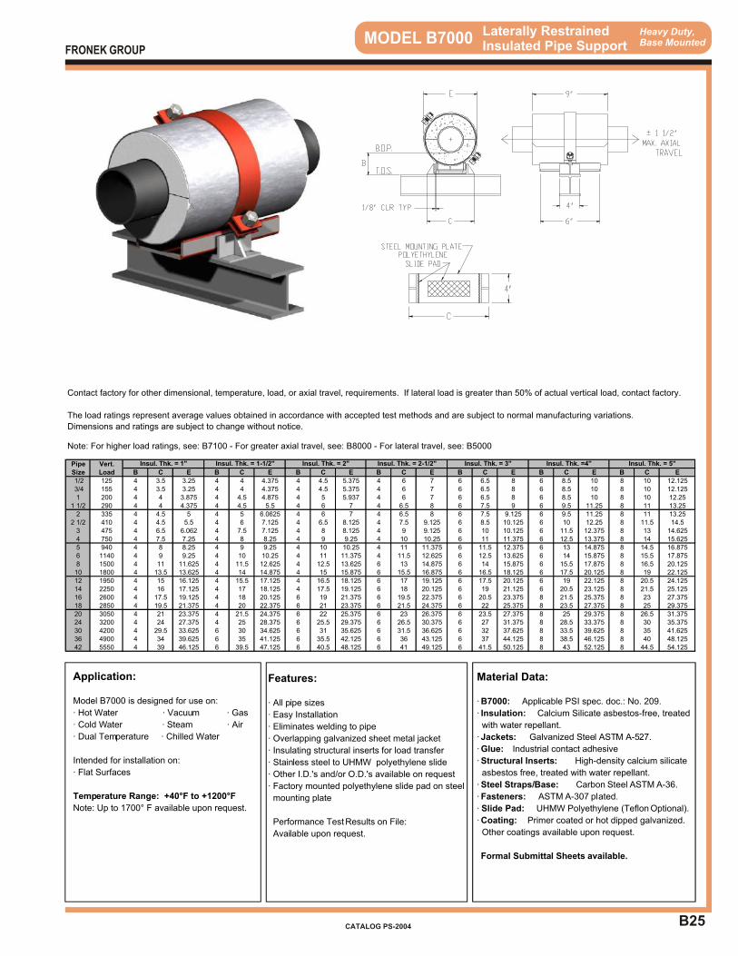
B25
Heavy Duty,Base Mounted MODEL B7000 Laterally Restrained
Insulated Pipe Support
Application:
Model B7000 is designed for use on:
· Hot Water · Vacuum · Gas
· Cold Water · Steam · Air
· Dual Temperature · Chilled Water
Intended for installation on:
· Flat Surfaces
Temperature Range: +40°F to +1200°F
Note: Up to 1700° F available upon request.
Features:
· All pipe sizes
· Easy Installation
· Eliminates welding to pipe
· Overlapping galvanized sheet metal jacket
· Insulating structural inserts for load transfer
· Stainless steel to UHMW polyethylene slide
· Other I.D.'s and/or O.D.'s available on request
· Factory mounted polyethylene slide pad on steel
mounting plate
Performance Test Results on File:
Available upon request.
Material Data:
· B7000: Applicable PSI spec. doc.: No. 209.
· Insulation: Calcium Silicate asbestos-free, treated
with water repellant.
· Jackets: Galvanized Steel ASTM A-527.
· Glue: Industrial contact adhesive
· Structural Inserts: High-density calcium silicate
asbestos free, treated with water repellant.
· Steel Straps/Base: Carbon Steel ASTM A-36.
· Fasteners: ASTM A-307 plated.
· Slide Pad: UHMW Polyethylene (Teflon Optional).
· Coating: Primer coated or hot dipped galvanized.
Other coatings available upon request.
Formal Submittal Sheets available.
FRONEK GROUP
CATALOG PS-2004
Contact factory for other dimensional, temperature, load, or axial travel, requirements. If lateral load is greater than 50% of actual vertical load, contact factory.
The load ratings represent average values obtained in accordance with accepted test methods and are subject to normal manufacturing variations.
Dimensions and ratings are subject to change without notice.
Note: For higher load ratings, see: B7100 - For greater axial travel, see: B8000 - For lateral travel, see: B5000
Pipe Vert.Size Load B C E B C E B C E B C E B C E B C E B C E
1/2 125 4 3.5 3.25 4 4 4.375 4 4.5 5.375 4 6 7 6 6.5 8 6 8.5 10 8 10 12.125 3/4 155 4 3.5 3.25 4 4 4.375 4 4.5 5.375 4 6 7 6 6.5 8 6 8.5 10 8 10 12.1251 200 4 4 3.875 4 4.5 4.875 4 5 5.937 4 6 7 6 6.5 8 6 8.5 10 8 10 12.25
1 1/2 290 4 4 4.375 4 4.5 5.5 4 6 7 4 6.5 8 6 7.5 9 6 9.5 11.25 8 11 13.252 335 4 4.5 5 4 5 6.0625 4 6 7 4 6.5 8 6 7.5 9.125 6 9.5 11.25 8 11 13.25
2 1/2 410 4 4.5 5.5 4 6 7.125 4 6.5 8.125 4 7.5 9.125 6 8.5 10.125 6 10 12.25 8 11.5 14.53 475 4 6.5 6.062 4 7.5 7.125 4 8 8.125 4 9 9.125 6 10 10.125 6 11.5 12.375 8 13 14.6254 750 4 7.5 7.25 4 8 8.25 4 9 9.25 4 10 10.25 6 11 11.375 6 12.5 13.375 8 14 15.6255 940 4 8 8.25 4 9 9.25 4 10 10.25 4 11 11.375 6 11.5 12.375 6 13 14.875 8 14.5 16.8756 1140 4 9 9.25 4 10 10.25 4 11 11.375 4 11.5 12.625 6 12.5 13.625 6 14 15.875 8 15.5 17.8758 1500 4 11 11.625 4 11.5 12.625 4 12.5 13.625 6 13 14.875 6 14 15.875 6 15.5 17.875 8 16.5 20.12510 1800 4 13.5 13.625 4 14 14.875 4 15 15.875 6 15.5 16.875 6 16.5 18.125 6 17.5 20.125 8 19 22.12512 1950 4 15 16.125 4 15.5 17.125 4 16.5 18.125 6 17 19.125 6 17.5 20.125 6 19 22.125 8 20.5 24.12514 2250 4 16 17.125 4 17 18.125 4 17.5 19.125 6 18 20.125 6 19 21.125 6 20.5 23.125 8 21.5 25.12516 2600 4 17.5 19.125 4 18 20.125 6 19 21.375 6 19.5 22.375 6 20.5 23.375 8 21.5 25.375 8 23 27.37518 2850 4 19.5 21.375 4 20 22.375 6 21 23.375 6 21.5 24.375 6 22 25.375 8 23.5 27.375 8 25 29.37520 3050 4 21 23.375 4 21.5 24.375 6 22 25.375 6 23 26.375 6 23.5 27.375 8 25 29.375 8 26.5 31.37524 3200 4 24 27.375 4 25 28.375 6 25.5 29.375 6 26.5 30.375 6 27 31.375 8 28.5 33.375 8 30 35.37530 4200 4 29.5 33.625 6 30 34.625 6 31 35.625 6 31.5 36.625 6 32 37.625 8 33.5 39.625 8 35 41.62536 4900 4 34 39.625 6 35 41.125 6 35.5 42.125 6 36 43.125 6 37 44.125 8 38.5 46.125 8 40 48.12542 5550 4 39 46.125 6 39.5 47.125 6 40.5 48.125 6 41 49.125 6 41.5 50.125 8 43 52.125 8 44.5 54.125
Insul. Thk. = 3" Insul. Thk. =4" Insul. Thk. = 5"Insul. Thk. = 1" Insul. Thk. = 1-1/2" Insul. Thk. = 2" Insul. Thk. = 2-1/2"

B26
Heavy Duty,Base Mounted MODEL B7100 Laterally Restrained
Insulated Pipe Support
Application:
Model B7100 is designed for use on:
· Hot Water · Vacuum · Gas
· Cold Water · Steam · Air
· Dual Temperature · Chilled Water
Intended for installation on:
· Flat Surfaces
Temperature Range: +40°F to +1200°F
Note: Up to 1700° F available upon request.
Features:
· All pipe sizes
· Easy Installation
· Eliminates welding to pipe
· Overlapping galvanized sheet metal jacket
· Insulating structural inserts for load transfer
· Stainless steel to UHMW polyethylene slide
· Other I.D.'s and/or O.D.'s available on request
· Factory mounted polyethylene slide pad on steel
mounting plate
Performance Test Results on File:
Available upon request.
Material Data:
· B7100: Applicable PSI spec. doc.: No. 209.
· Insulation: Calcium Silicate asbestos-free, treated
with water repellant.
· Jackets: Galvanized Steel ASTM A-527.
· Glue: Industrial contact adhesive
· Structural Inserts: High-density calcium silicate
asbestos free, treated with water repellant.
· Steel Straps/Base: Carbon Steel ASTM A-36.
· Fasteners: ASTM A-307 plated.
· Slide Pad: UHMW Polyethylene (Teflon Optional).
· Coating: Primer coated or hot dipped galvanized.
Other coatings available upon request.
Formal Submittal Sheets available.
FRONEK GROUP
CATALOG PS-2004
Contact factory for other dimensional, temperature, load, or axial travel, requirements. If lateral load is greater than 50% of actual vertical load,
contact factory.
The load ratings represent average values obtained in accordance with accepted test methods and are subject to normal manufacturing variations.
Dimensions and ratings are subject to change without notice.
Note: For higher load ratings, see: B7200 - For lateral restraint, see: B8100 - For minimal lateral travel, see: B5100
Pipe Vert.Size Load B C E B C E B C E B C E B C E B C E B C E
1/2 250 4 5 3.25 4 5.5 4.375 4 6 5.375 4 7.5 7 6 8 8 6 10 10 8 11.5 12.125 3/4 310 4 5 3.25 4 5.5 4.375 4 6 5.375 4 7.5 7 6 8 8 6 10 10 8 11.5 12.251 400 4 5.5 3.875 4 6 5 4 6.5 6.062 4 7.5 7 6 8 8 6 10 10 8 11.5 12.25
1 1/2 580 4 5.5 4.5 4 6 5.5 4 7.5 7.125 4 8 8.125 6 9 9.125 6 11 11.25 8 12.5 13.252 670 4 6 5 4 6.5 6.0625 4 7.5 7.125 4 8 8.125 6 9 9.125 6 11 11.25 8 12.5 13.25
2 1/2 820 4 6.5 5.5 4 8 7.125 4 8.5 8.125 4 9.5 9.125 6 10.5 10.125 6 12 12.25 8 13.5 14.53 950 4 7 6.187 4 8 7.125 4 8.5 8.125 4 9.5 9.125 6 10.5 10.125 6 12 12.375 8 13.5 14.6254 1500 4 8.5 7.25 4 9 8.25 4 10 9.25 4 11 10.25 6 12 11.375 6 13.5 13.375 8 15 15.6255 1880 4 9.5 8.5 4 10.5 9.5 4 11.5 10.5 4 12.5 11.625 6 13 12.625 6 14.5 14.875 8 16 16.8756 2280 4 10 9.5 4 11 10.5 4 12 11.625 4 12.5 12.625 6 13.5 13.625 6 15 15.875 8 16.5 17.8758 3000 4 13 11.625 4 13.5 12.625 4 14.5 13.625 6 15 14.875 6 16 15.875 6 17.5 18.125 8 18.5 20.12510 3600 4 14.5 13.875 4 15 15.125 4 16 16.125 6 16.5 17.125 6 17.5 18.125 6 18.5 20.125 8 20 22.12512 3900 4 16.5 16.125 4 17 17.125 4 18 18.125 6 18.5 19.125 6 19 20.125 6 20.5 22.125 8 22 24.12514 4500 4 17.5 17.125 4 18.5 18.125 4 19 19.125 6 19.5 20.125 6 20.5 21.125 6 22 23.125 8 23 25.12516 5200 4 19 19.375 4 19.5 20.375 6 20.5 21.375 6 21 22.375 6 22 23.375 8 23 25.375 8 24.5 27.37518 5700 4 21 21.375 4 21.5 22.375 6 22.5 23.375 6 23 24.375 6 23.5 25.375 8 25 27.375 8 26.5 29.37520 6100 4 22.5 23.375 4 23 24.375 6 23.5 25.375 6 24.5 26.375 6 25 27.375 8 26.5 29.375 8 28 31.37524 6400 4 25.5 27.375 4 26.5 28.375 6 27 29.375 6 28 30.375 6 28.5 31.375 8 30 33.375 8 31.5 35.37530 8400 4 31.5 33.625 6 32 34.625 6 33 35.625 6 33.5 36.625 6 34 37.625 8 35.5 39.625 8 37 41.62536 9800 4 36 40.125 6 37 41.125 6 37.5 42.125 6 38 43.125 6 39 44.125 8 40.5 46.125 8 42 48.12542 11100 4 41.5 46.125 6 42 47.125 6 43 48.125 6 43.5 49.125 6 44 50.125 8 45.5 52.125 8 47 54.125
Insul. Thk. = 3" Insul. Thk. =4" Insul. Thk. = 5"Insul. Thk. = 1" Insul. Thk. = 1-1/2" Insul. Thk. = 2" Insul. Thk. = 2-1/2"
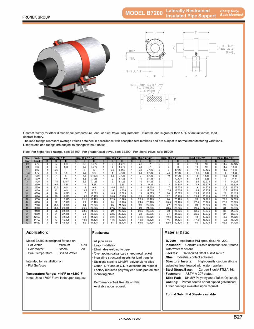
B27
Heavy Duty,Base Mounted MODEL B7200 Laterally Restrained
Insulated Pipe Support
Application:
Model B7200 is designed for use on:
· Hot Water · Vacuum · Gas
· Cold Water · Steam · Air
· Dual Temperature · Chilled Water
Intended for installation on:
· Flat Surfaces
Temperature Range: +40°F to +1200°F
Note: Up to 1700° F available upon request.
Features:
· All pipe sizes
· Easy Installation
· Eliminates welding to pipe
· Overlapping galvanized sheet metal jacket
· Insulating structural inserts for load transfer
· Stainless steel to UHMW polyethylene slide
· Other I.D.'s and/or O.D.'s available on request
· Factory mounted polyethylene slide pad on steel
mounting plate
Performance Test Results on File:
Available upon request.
Material Data:
· B7200: Applicable PSI spec. doc.: No. 209.
· Insulation: Calcium Silicate asbestos-free, treated
with water repellant.
· Jackets: Galvanized Steel ASTM A-527.
· Glue: Industrial contact adhesive
· Structural Inserts: High-density calcium silicate
asbestos free, treated with water repellant.
· Steel Straps/Base: Carbon Steel ASTM A-36.
· Fasteners: ASTM A-307 plated.
· Slide Pad: UHMW Polyethylene (Teflon Optional).
· Coating: Primer coated or hot dipped galvanized.
Other coatings available upon request.
Formal Submittal Sheets available.
FRONEK GROUP
CATALOG PS-2004
Contact factory for other dimensional, temperature, load, or axial travel, requirements. If lateral load is greater than 50% of actual vertical load,
contact factory.
The load ratings represent average values obtained in accordance with accepted test methods and are subject to normal manufacturing variations.
Dimensions and ratings are subject to change without notice.
Note: For higher load ratings, see: B7300 - For greater axial travel, see: B8200 - For lateral travel, see: B5200
Pipe Vert.Size Load B C E B C E B C E B C E B C E B C E B C E
1/2 375 4 5 3.25 4 5.5 4.375 4 6 5.375 4 7.5 7 6 8 8 6 10 10 8 11.5 12.125 3/4 465 4 5 3.25 4 5.5 4.375 4 6 5.375 4 7.5 7 6 8 8 6 10 10 8 11.5 12.251 600 4 5.5 4 4 6 5 4 6.5 6.062 4 7.5 7.125 6 8 8.125 6 10 10.125 8 11.5 12.25
1 1/2 870 4 6 4.5 4 6.5 5.5 4 8 7.125 4 8.5 8.125 6 9.5 9.125 6 11.5 11.25 8 13 13.252 1005 4 7 5 4 7.5 6.1875 4 8.5 7.125 4 9 8.125 6 10 9.125 6 12 11.25 8 13.5 13.25
2 1/2 1230 4 7 5.5 4 8.5 7.125 4 9 8.125 4 10 9.125 6 11 10.125 6 12.5 12.25 8 14 14.53 1425 4 7.5 6.187 4 8.5 7.125 4 9 8.125 4 10 9.125 6 11 10.125 6 12.5 12.375 8 14 14.6254 2250 4 9.5 7.25 4 10 8.25 4 11 9.25 4 12 10.25 6 13 11.375 6 14.5 13.375 8 16 15.6255 2820 4 12.5 8.5 4 13 9.5 4 14.5 10.5 4 16 11.625 6 17 12.625 6 19 14.875 8 20.5 16.8756 3420 4 12 9.5 4 13.5 10.5 4 15 11.625 4 16 12.625 6 17.5 13.625 6 18.5 15.875 8 20.5 17.8758 4500 4 16 11.625 4 17 12.625 4 18.5 13.625 6 19 14.875 6 20 15.875 6 21.5 18.125 8 23 20.12510 5400 4 19 13.875 4 19.5 15.125 4 20.5 16.125 6 21 17.125 6 22 18.125 6 23.5 20.125 8 25.5 22.12512 5850 4 21 16.125 4 21.5 17.125 4 22.5 18.125 6 23.5 19.125 6 24 20.125 6 26 22.125 8 27.5 24.12514 6750 4 22 17.125 4 23 18.125 4 24 19.125 6 24.5 20.125 6 25.5 21.125 6 27.5 23.125 8 28.5 25.12516 7800 4 23.5 19.375 4 24 20.375 6 25 21.375 6 26 22.375 6 27 23.375 8 28 25.375 8 29 27.37518 8550 4 25.5 21.375 4 26.5 22.375 6 27.5 23.375 6 28 24.375 6 28.5 25.375 8 29.5 27.375 8 31 29.37520 9150 4 28 23.375 4 28.5 24.375 6 29 25.375 6 29.5 26.375 6 30 27.375 8 31.5 29.375 8 33 31.37524 9600 4 31 27.375 4 32 28.375 6 32.5 29.375 6 33 30.375 6 34 31.375 8 35.5 33.375 8 37 35.37530 12600 4 37 33.625 6 38 34.625 6 38.5 35.625 6 39.5 36.625 6 40.5 37.625 8 42 39.625 8 43.5 41.62536 14700 4 43 40.125 6 43.5 41.125 6 44.5 42.125 6 45.5 43.125 6 46 44.125 8 47.5 46.125 8 49.5 48.12542 16650 4 49 46.125 6 50 47.125 6 51 48.125 6 51.5 49.125 6 52.5 50.125 8 54 52.125 8 55.5 54.125
Insul. Thk. = 3" Insul. Thk. =4" Insul. Thk. = 5"Insul. Thk. = 1" Insul. Thk. = 1-1/2" Insul. Thk. = 2" Insul. Thk. = 2-1/2"
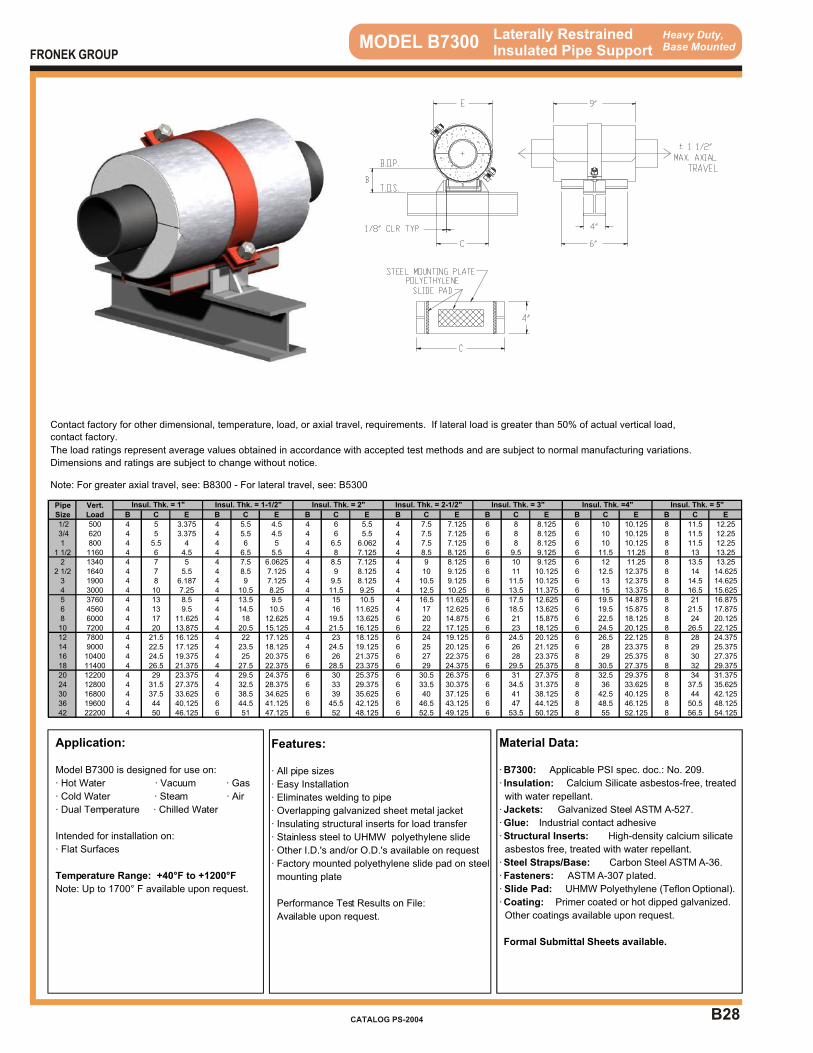
B28
Heavy Duty,Base Mounted MODEL B7300
Application:
Model B7300 is designed for use on:
· Hot Water · Vacuum · Gas
· Cold Water · Steam · Air
· Dual Temperature · Chilled Water
Intended for installation on:
· Flat Surfaces
Temperature Range: +40°F to +1200°F
Note: Up to 1700° F available upon request.
Features:
· All pipe sizes
· Easy Installation
· Eliminates welding to pipe
· Overlapping galvanized sheet metal jacket
· Insulating structural inserts for load transfer
· Stainless steel to UHMW polyethylene slide
· Other I.D.'s and/or O.D.'s available on request
· Factory mounted polyethylene slide pad on steel
mounting plate
Performance Test Results on File:
Available upon request.
Material Data:
· B7300: Applicable PSI spec. doc.: No. 209.
· Insulation: Calcium Silicate asbestos-free, treated
with water repellant.
· Jackets: Galvanized Steel ASTM A-527.
· Glue: Industrial contact adhesive
· Structural Inserts: High-density calcium silicate
asbestos free, treated with water repellant.
· Steel Straps/Base: Carbon Steel ASTM A-36.
· Fasteners: ASTM A-307 plated.
· Slide Pad: UHMW Polyethylene (Teflon Optional).
· Coating: Primer coated or hot dipped galvanized.
Other coatings available upon request.
Formal Submittal Sheets available.
Laterally RestrainedInsulated Pipe SupportFRONEK GROUP
CATALOG PS-2004
Contact factory for other dimensional, temperature, load, or axial travel, requirements. If lateral load is greater than 50% of actual vertical load,
contact factory.
The load ratings represent average values obtained in accordance with accepted test methods and are subject to normal manufacturing variations.
Dimensions and ratings are subject to change without notice.
Note: For greater axial travel, see: B8300 - For lateral travel, see: B5300
Pipe Vert.Size Load B C E B C E B C E B C E B C E B C E B C E
1/2 500 4 5 3.375 4 5.5 4.5 4 6 5.5 4 7.5 7.125 6 8 8.125 6 10 10.125 8 11.5 12.25 3/4 620 4 5 3.375 4 5.5 4.5 4 6 5.5 4 7.5 7.125 6 8 8.125 6 10 10.125 8 11.5 12.251 800 4 5.5 4 4 6 5 4 6.5 6.062 4 7.5 7.125 6 8 8.125 6 10 10.125 8 11.5 12.25
1 1/2 1160 4 6 4.5 4 6.5 5.5 4 8 7.125 4 8.5 8.125 6 9.5 9.125 6 11.5 11.25 8 13 13.252 1340 4 7 5 4 7.5 6.0625 4 8.5 7.125 4 9 8.125 6 10 9.125 6 12 11.25 8 13.5 13.25
2 1/2 1640 4 7 5.5 4 8.5 7.125 4 9 8.125 4 10 9.125 6 11 10.125 6 12.5 12.375 8 14 14.6253 1900 4 8 6.187 4 9 7.125 4 9.5 8.125 4 10.5 9.125 6 11.5 10.125 6 13 12.375 8 14.5 14.6254 3000 4 10 7.25 4 10.5 8.25 4 11.5 9.25 4 12.5 10.25 6 13.5 11.375 6 15 13.375 8 16.5 15.6255 3760 4 13 8.5 4 13.5 9.5 4 15 10.5 4 16.5 11.625 6 17.5 12.625 6 19.5 14.875 8 21 16.8756 4560 4 13 9.5 4 14.5 10.5 4 16 11.625 4 17 12.625 6 18.5 13.625 6 19.5 15.875 8 21.5 17.8758 6000 4 17 11.625 4 18 12.625 4 19.5 13.625 6 20 14.875 6 21 15.875 6 22.5 18.125 8 24 20.12510 7200 4 20 13.875 4 20.5 15.125 4 21.5 16.125 6 22 17.125 6 23 18.125 6 24.5 20.125 8 26.5 22.12512 7800 4 21.5 16.125 4 22 17.125 4 23 18.125 6 24 19.125 6 24.5 20.125 6 26.5 22.125 8 28 24.37514 9000 4 22.5 17.125 4 23.5 18.125 4 24.5 19.125 6 25 20.125 6 26 21.125 6 28 23.375 8 29 25.37516 10400 4 24.5 19.375 4 25 20.375 6 26 21.375 6 27 22.375 6 28 23.375 8 29 25.375 8 30 27.37518 11400 4 26.5 21.375 4 27.5 22.375 6 28.5 23.375 6 29 24.375 6 29.5 25.375 8 30.5 27.375 8 32 29.37520 12200 4 29 23.375 4 29.5 24.375 6 30 25.375 6 30.5 26.375 6 31 27.375 8 32.5 29.375 8 34 31.37524 12800 4 31.5 27.375 4 32.5 28.375 6 33 29.375 6 33.5 30.375 6 34.5 31.375 8 36 33.625 8 37.5 35.62530 16800 4 37.5 33.625 6 38.5 34.625 6 39 35.625 6 40 37.125 6 41 38.125 8 42.5 40.125 8 44 42.12536 19600 4 44 40.125 6 44.5 41.125 6 45.5 42.125 6 46.5 43.125 6 47 44.125 8 48.5 46.125 8 50.5 48.12542 22200 4 50 46.125 6 51 47.125 6 52 48.125 6 52.5 49.125 6 53.5 50.125 8 55 52.125 8 56.5 54.125
Insul. Thk. = 3" Insul. Thk. =4" Insul. Thk. = 5"Insul. Thk. = 1" Insul. Thk. = 1-1/2" Insul. Thk. = 2" Insul. Thk. = 2-1/2"
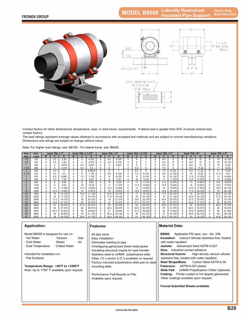
B29
Heavy Duty,Base Mounted MODEL B8000 Laterally Restrained
Insulated Pipe Support
Application:
Model B8000 is designed for use on:
· Hot Water · Vacuum · Gas
· Cold Water · Steam · Air
· Dual Temperature · Chilled Water
Intended for installation on:
· Flat Surfaces
Temperature Range: +40°F to +1200°F
Note: Up to 1700° F available upon request.
Features:
· All pipe sizes
· Easy Installation
· Eliminates welding to pipe
· Overlapping galvanized sheet metal jacket
· Insulating structural inserts for load transfer
· Stainless steel to UHMW polyethylene slide
· Other I.D.'s and/or O.D.'s available on request
· Factory mounted polyethylene slide pad on steel
mounting plate
Performance Test Results on File:
Available upon request.
Material Data:
· B8000: Applicable PSI spec. doc.: No. 209.
· Insulation: Calcium Silicate asbestos-free, treated
with water repellant.
· Jackets: Galvanized Steel ASTM A-527.
· Glue: Industrial contact adhesive
· Structural Inserts: High-density calcium silicate
asbestos free, treated with water repellant.
· Steel Straps/Base: Carbon Steel ASTM A-36.
· Fasteners: ASTM A-307 plated.
· Slide Pad: UHMW Polyethylene (Teflon Optional).
· Coating: Primer coated or hot dipped galvanized.
Other coatings available upon request.
Formal Submittal Sheets available.
FRONEK GROUP
CATALOG PS-2004
Contact factory for other dimensional, temperature, load, or axial travel, requirements. If lateral load is greater than 50% of actual vertical load,
contact factory.
The load ratings represent average values obtained in accordance with accepted test methods and are subject to normal manufacturing variations.
Dimensions and ratings are subject to change without notice.
Note: For higher load ratings, see: B8100 - For lateral travel, see: B6000
Pipe Vert.Size Load B C E B C E B C E B C E B C E B C E B C E
1/2 125 4 3.5 3.25 4 4 4.375 4 4.5 5.375 4 6 7 6 6.5 8 6 8.5 10 8 10 12.125 3/4 155 4 3.5 3.25 4 4 4.375 4 4.5 5.375 4 6 7 6 6.5 8 6 8.5 10 8 10 12.1251 200 4 4 3.875 4 4.5 4.875 4 5 5.937 4 6 7 6 6.5 8 6 8.5 10 8 10 12.25
1 1/2 290 4 4 4.375 4 4.5 5.5 4 6 7 4 6.5 8 6 7.5 9 6 9.5 11.25 8 11 13.252 335 4 4.5 5 4 5 6.0625 4 6 7 4 6.5 8 6 7.5 9.125 6 9.5 11.25 8 11 13.25
2 1/2 410 4 4.5 5.5 4 6 7.125 4 6.5 8.125 4 7.5 9.125 6 8.5 10.125 6 10 12.25 8 11.5 14.53 475 4 6.5 6.062 4 7.5 7.125 4 8 8.125 4 9 9.125 6 10 10.125 6 11.5 12.375 8 13 14.6254 750 4 7.5 7.25 4 8 8.25 4 9 9.25 4 10 10.25 6 11 11.375 6 12.5 13.375 8 14 15.6255 940 4 8 8.25 4 9 9.25 4 10 10.25 4 11 11.375 6 11.5 12.375 6 13 14.875 8 14.5 16.8756 1140 4 9 9.25 4 10 10.25 4 11 11.375 4 11.5 12.625 6 12.5 13.625 6 14 15.875 8 15.5 17.8758 1500 4 11 11.625 4 11.5 12.625 4 12.5 13.625 6 13 14.875 6 14 15.875 6 15.5 17.875 8 16.5 20.12510 1800 4 13.5 13.625 4 14 14.875 4 15 15.875 6 15.5 16.875 6 16.5 18.125 6 17.5 20.125 8 19 22.12512 1950 4 15 16.125 4 15.5 17.125 4 16.5 18.125 6 17 19.125 6 17.5 20.125 6 19 22.125 8 20.5 24.12514 2250 4 16 17.125 4 17 18.125 4 17.5 19.125 6 18 20.125 6 19 21.125 6 20.5 23.125 8 21.5 25.12516 2600 4 17.5 19.125 4 18 20.125 6 19 21.375 6 19.5 22.375 6 20.5 23.375 8 21.5 25.375 8 23 27.37518 2850 4 19.5 21.375 4 20 22.375 6 21 23.375 6 21.5 24.375 6 22 25.375 8 23.5 27.375 8 25 29.37520 3050 4 21 23.375 4 21.5 24.375 6 22 25.375 6 23 26.375 6 23.5 27.375 8 25 29.375 8 26.5 31.37524 3200 4 24 27.375 4 25 28.375 6 25.5 29.375 6 26.5 30.375 6 27 31.375 8 28.5 33.375 8 30 35.37530 4200 4 29.5 33.625 6 30 34.625 6 31 35.625 6 31.5 36.625 6 32 37.625 8 33.5 39.625 8 35 41.62536 4900 4 34 39.625 6 35 41.125 6 35.5 42.125 6 36 43.125 6 37 44.125 8 38.5 46.125 8 40 48.12542 5550 4 39 46.125 6 39.5 47.125 6 40.5 48.125 6 41 49.125 6 41.5 50.125 8 43 52.125 8 44.5 54.125
Insul. Thk. = 3" Insul. Thk. =4" Insul. Thk. = 5"Insul. Thk. = 1" Insul. Thk. = 1-1/2" Insul. Thk. = 2" Insul. Thk. = 2-1/2"

B30
Heavy Duty,Base Mounted MODEL B8100 Laterally Restrained
Insulated Pipe Support
Application:
Model B8100 is designed for use on:
· Hot Water · Vacuum · Gas
· Cold Water · Steam · Air
· Dual Temperature · Chilled Water
Intended for installation on:
· Flat Surfaces
Temperature Range: +40°F to +1200°F
Note: Up to 1700° F available upon request.
Features:
· All pipe sizes
· Easy Installation
· Eliminates welding to pipe
· Overlapping galvanized sheet metal jacket
· Insulating structural inserts for load transfer
· Stainless steel to UHMW polyethylene slide
· Other I.D.'s and/or O.D.'s available on request
· Factory mounted polyethylene slide pad on steel
mounting plate
Performance Test Results on File:
Available upon request.
Material Data:
· B8100: Applicable PSI spec. doc.: No. 209.
· Insulation: Calcium Silicate asbestos-free, treated
with water repellant.
· Jackets: Galvanized Steel ASTM A-527.
· Glue: Industrial contact adhesive
· Structural Inserts: High-density calcium silicate
asbestos free, treated with water repellant.
· Steel Straps/Base: Carbon Steel ASTM A-36.
· Fasteners: ASTM A-307 plated.
· Slide Pad: UHMW Polyethylene (Teflon Optional).
· Coating: Primer coated or hot dipped galvanized.
Other coatings available upon request.
Formal Submittal Sheets available.
FRONEK GROUP
CATALOG PS-2004
Contact factory for other dimensional, temperature, load, or axial travel, requirements. If lateral load is greater than 50% of actual vertical load,
contact factory.
The load ratings represent average values obtained in accordance with accepted test methods and are subject to normal manufacturing variations.
Dimensions and ratings are subject to change without notice.
Note: For higher load ratings, see: B8200 - For lateral travel, see: B6100
Pipe Vert.Size Load B C E B C E B C E B C E B C E B C E B C E
1/2 250 4 5 3.25 4 5.5 4.375 4 6 5.375 4 7.5 7 6 8 8 6 10 10 8 11.5 12.125 3/4 310 4 5 3.25 4 5.5 4.375 4 6 5.375 4 7.5 7 6 8 8 6 10 10 8 11.5 12.251 400 4 5.5 3.875 4 6 5 4 6.5 6.062 4 7.5 7 6 8 8 6 10 10 8 11.5 12.25
1 1/2 580 4 5.5 4.5 4 6 5.5 4 7.5 7.125 4 8 8.125 6 9 9.125 6 11 11.25 8 12.5 13.252 670 4 6 5 4 6.5 6.0625 4 7.5 7.125 4 8 8.125 6 9 9.125 6 11 11.25 8 12.5 13.25
2 1/2 820 4 6.5 5.5 4 8 7.125 4 8.5 8.125 4 9.5 9.125 6 10.5 10.125 6 12 12.25 8 13.5 14.53 950 4 7 6.187 4 8 7.125 4 8.5 8.125 4 9.5 9.125 6 10.5 10.125 6 12 12.375 8 13.5 14.6254 1500 4 8.5 7.25 4 9 8.25 4 10 9.25 4 11 10.25 6 12 11.375 6 13.5 13.375 8 15 15.6255 1880 4 9.5 8.5 4 10.5 9.5 4 11.5 10.5 4 12.5 11.625 6 13 12.625 6 14.5 14.875 8 16 16.8756 2280 4 10 9.5 4 11 10.5 4 12 11.625 4 12.5 12.625 6 13.5 13.625 6 15 15.875 8 16.5 17.8758 3000 4 13 11.625 4 13.5 12.625 4 14.5 13.625 6 15 14.875 6 16 15.875 6 17.5 18.125 8 18.5 20.12510 3600 4 14.5 13.875 4 15 15.125 4 16 16.125 6 16.5 17.125 6 17.5 18.125 6 18.5 20.125 8 20 22.12512 3900 4 16.5 16.125 4 17 17.125 4 18 18.125 6 18.5 19.125 6 19 20.125 6 20.5 22.125 8 22 24.12514 4500 4 17.5 17.125 4 18.5 18.125 4 19 19.125 6 19.5 20.125 6 20.5 21.125 6 22 23.125 8 23 25.12516 5200 4 19 19.375 4 19.5 20.375 6 20.5 21.375 6 21 22.375 6 22 23.375 8 23 25.375 8 24.5 27.37518 5700 4 21 21.375 4 21.5 22.375 6 22.5 23.375 6 23 24.375 6 23.5 25.375 8 25 27.375 8 26.5 29.37520 6100 4 22.5 23.375 4 23 24.375 6 23.5 25.375 6 24.5 26.375 6 25 27.375 8 26.5 29.375 8 28 31.37524 6400 4 25.5 27.375 4 26.5 28.375 6 27 29.375 6 28 30.375 6 28.5 31.375 8 30 33.375 8 31.5 35.37530 8400 4 31.5 33.625 6 32 34.625 6 33 35.625 6 33.5 36.625 6 34 37.625 8 35.5 39.625 8 37 41.62536 9800 4 36 40.125 6 37 41.125 6 37.5 42.125 6 38 43.125 6 39 44.125 8 40.5 46.125 8 42 48.12542 11100 4 41.5 46.125 6 42 47.125 6 43 48.125 6 43.5 49.125 6 44 50.125 8 45.5 52.125 8 47 54.125
Insul. Thk. = 3" Insul. Thk. =4" Insul. Thk. = 5"Insul. Thk. = 1" Insul. Thk. = 1-1/2" Insul. Thk. = 2" Insul. Thk. = 2-1/2"

B31
Heavy Duty,Base Mounted MODEL B8200 Laterally Restrained
Insulated Pipe Support
Application:
Model B8200 is designed for use on:
· Hot Water · Vacuum · Gas
· Cold Water · Steam · Air
· Dual Temperature · Chilled Water
Intended for installation on:
· Flat Surfaces
Temperature Range: +40°F to +1200°F
Note: Up to 1700° F available upon request.
Features:
· All pipe sizes
· Easy Installation
· Eliminates welding to pipe
· Overlapping galvanized sheet metal jacket
· Insulating structural inserts for load transfer
· Stainless steel to UHMW polyethylene slide
· Other I.D.'s and/or O.D.'s available on request
· Factory mounted polyethylene slide pad on steel
mounting plate
Performance Test Results on File:
Available upon request.
Material Data:
· B8200: Applicable PSI spec. doc.: No. 209.
· Insulation: Calcium Silicate asbestos-free, treated
with water repellant.
· Jackets: Galvanized Steel ASTM A-527.
· Glue: Industrial contact adhesive
· Structural Inserts: High-density calcium silicate
asbestos free, treated with water repellant.
· Steel Straps/Base: Carbon Steel ASTM A-36.
· Fasteners: ASTM A-307 plated.
· Slide Pad: UHMW Polyethylene (Teflon Optional).
· Coating: Primer coated or hot dipped galvanized.
Other coatings available upon request.
Formal Submittal Sheets available.
FRONEK GROUP
CATALOG PS-2004
Contact factory for other dimensional, temperature, load, or axial travel, requirements. If lateral load is greater than 50% of actual vertical load,
contact factory.
The load ratings represent average values obtained in accordance with accepted test methods and are subject to normal manufacturing variations.
Dimensions and ratings are subject to change without notice.
Note: For higher load ratings, see: B8300 - For lateral travel, see: B6200
Pipe Vert.Size Load B C E B C E B C E B C E B C E B C E B C E
1/2 375 4 5 3.25 4 5.5 4.375 4 6 5.375 4 7.5 7 6 8 8 6 10 10 8 11.5 12.125 3/4 465 4 5 3.25 4 5.5 4.375 4 6 5.375 4 7.5 7 6 8 8 6 10 10 8 11.5 12.251 600 4 5.5 4 4 6 5 4 6.5 6.062 4 7.5 7.125 6 8 8.125 6 10 10.125 8 11.5 12.25
1 1/2 870 4 6 4.5 4 6.5 5.5 4 8 7.125 4 8.5 8.125 6 9.5 9.125 6 11.5 11.25 8 13 13.252 1005 4 7 5 4 7.5 6.1875 4 8.5 7.125 4 9 8.125 6 10 9.125 6 12 11.25 8 13.5 13.25
2 1/2 1230 4 7 5.5 4 8.5 7.125 4 9 8.125 4 10 9.125 6 11 10.125 6 12.5 12.25 8 14 14.53 1425 4 7.5 6.187 4 8.5 7.125 4 9 8.125 4 10 9.125 6 11 10.125 6 12.5 12.375 8 14 14.6254 2250 4 9.5 7.25 4 10 8.25 4 11 9.25 4 12 10.25 6 13 11.375 6 14.5 13.375 8 16 15.6255 2820 4 12.5 8.5 4 13 9.5 4 14.5 10.5 4 16 11.625 6 17 12.625 6 19 14.875 8 20.5 16.8756 3420 4 12 9.5 4 13.5 10.5 4 15 11.625 4 16 12.625 6 17.5 13.625 6 18.5 15.875 8 20.5 17.8758 4500 4 16 11.625 4 17 12.625 4 18.5 13.625 6 19 14.875 6 20 15.875 6 21.5 18.125 8 23 20.12510 5400 4 19 13.875 4 19.5 15.125 4 20.5 16.125 6 21 17.125 6 22 18.125 6 23.5 20.125 8 25.5 22.12512 5850 4 21 16.125 4 21.5 17.125 4 22.5 18.125 6 23.5 19.125 6 24 20.125 6 26 22.125 8 27.5 24.12514 6750 4 22 17.125 4 23 18.125 4 24 19.125 6 24.5 20.125 6 25.5 21.125 6 27.5 23.125 8 28.5 25.12516 7800 4 23.5 19.375 4 24 20.375 6 25 21.375 6 26 22.375 6 27 23.375 8 28 25.375 8 29 27.37518 8550 4 25.5 21.375 4 26.5 22.375 6 27.5 23.375 6 28 24.375 6 28.5 25.375 8 29.5 27.375 8 31 29.37520 9150 4 28 23.375 4 28.5 24.375 6 29 25.375 6 29.5 26.375 6 30 27.375 8 31.5 29.375 8 33 31.37524 9600 4 31 27.375 4 32 28.375 6 32.5 29.375 6 33 30.375 6 34 31.375 8 35.5 33.375 8 37 35.37530 12600 4 37 33.625 6 38 34.625 6 38.5 35.625 6 39.5 36.625 6 40.5 37.625 8 42 39.625 8 43.5 41.62536 14700 4 43 40.125 6 43.5 41.125 6 44.5 42.125 6 45.5 43.125 6 46 44.125 8 47.5 46.125 8 49.5 48.12542 16650 4 49 46.125 6 50 47.125 6 51 48.125 6 51.5 49.125 6 52.5 50.125 8 54 52.125 8 55.5 54.125
Insul. Thk. = 3" Insul. Thk. =4" Insul. Thk. = 5"Insul. Thk. = 1" Insul. Thk. = 1-1/2" Insul. Thk. = 2" Insul. Thk. = 2-1/2"
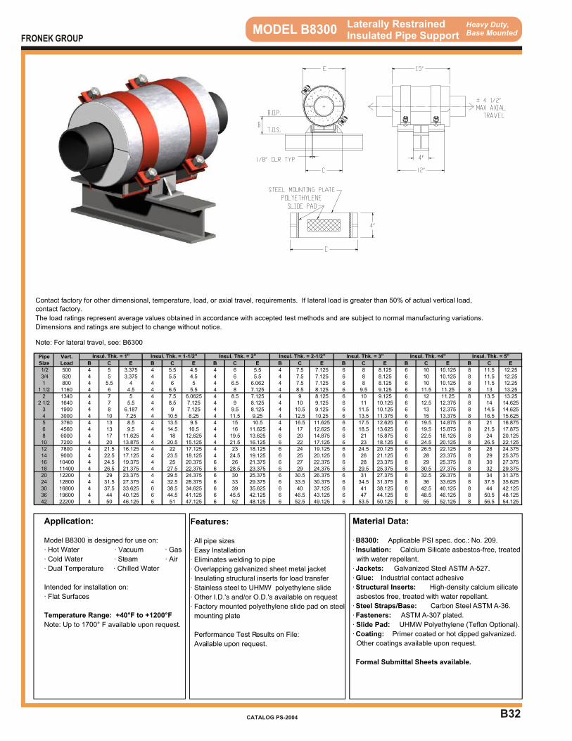
B32
Heavy Duty,Base Mounted MODEL B8300 Laterally Restrained
Insulated Pipe Support
Application:
Model B8300 is designed for use on:
· Hot Water · Vacuum · Gas
· Cold Water · Steam · Air
· Dual Temperature · Chilled Water
Intended for installation on:
· Flat Surfaces
Temperature Range: +40°F to +1200°F
Note: Up to 1700° F available upon request.
Features:
· All pipe sizes
· Easy Installation
· Eliminates welding to pipe
· Overlapping galvanized sheet metal jacket
· Insulating structural inserts for load transfer
· Stainless steel to UHMW polyethylene slide
· Other I.D.'s and/or O.D.'s available on request
· Factory mounted polyethylene slide pad on steel
mounting plate
Performance Test Results on File:
Available upon request.
Material Data:
· B8300: Applicable PSI spec. doc.: No. 209.
· Insulation: Calcium Silicate asbestos-free, treated
with water repellant.
· Jackets: Galvanized Steel ASTM A-527.
· Glue: Industrial contact adhesive
· Structural Inserts: High-density calcium silicate
asbestos free, treated with water repellant.
· Steel Straps/Base: Carbon Steel ASTM A-36.
· Fasteners: ASTM A-307 plated.
· Slide Pad: UHMW Polyethylene (Teflon Optional).
· Coating: Primer coated or hot dipped galvanized.
Other coatings available upon request.
Formal Submittal Sheets available.
FRONEK GROUP
CATALOG PS-2004
Contact factory for other dimensional, temperature, load, or axial travel, requirements. If lateral load is greater than 50% of actual vertical load,
contact factory.
The load ratings represent average values obtained in accordance with accepted test methods and are subject to normal manufacturing variations.
Dimensions and ratings are subject to change without notice.
Note: For lateral travel, see: B6300
Pipe Vert.Size Load B C E B C E B C E B C E B C E B C E B C E
1/2 500 4 5 3.375 4 5.5 4.5 4 6 5.5 4 7.5 7.125 6 8 8.125 6 10 10.125 8 11.5 12.25 3/4 620 4 5 3.375 4 5.5 4.5 4 6 5.5 4 7.5 7.125 6 8 8.125 6 10 10.125 8 11.5 12.251 800 4 5.5 4 4 6 5 4 6.5 6.062 4 7.5 7.125 6 8 8.125 6 10 10.125 8 11.5 12.25
1 1/2 1160 4 6 4.5 4 6.5 5.5 4 8 7.125 4 8.5 8.125 6 9.5 9.125 6 11.5 11.25 8 13 13.252 1340 4 7 5 4 7.5 6.0625 4 8.5 7.125 4 9 8.125 6 10 9.125 6 12 11.25 8 13.5 13.25
2 1/2 1640 4 7 5.5 4 8.5 7.125 4 9 8.125 4 10 9.125 6 11 10.125 6 12.5 12.375 8 14 14.6253 1900 4 8 6.187 4 9 7.125 4 9.5 8.125 4 10.5 9.125 6 11.5 10.125 6 13 12.375 8 14.5 14.6254 3000 4 10 7.25 4 10.5 8.25 4 11.5 9.25 4 12.5 10.25 6 13.5 11.375 6 15 13.375 8 16.5 15.6255 3760 4 13 8.5 4 13.5 9.5 4 15 10.5 4 16.5 11.625 6 17.5 12.625 6 19.5 14.875 8 21 16.8756 4560 4 13 9.5 4 14.5 10.5 4 16 11.625 4 17 12.625 6 18.5 13.625 6 19.5 15.875 8 21.5 17.8758 6000 4 17 11.625 4 18 12.625 4 19.5 13.625 6 20 14.875 6 21 15.875 6 22.5 18.125 8 24 20.12510 7200 4 20 13.875 4 20.5 15.125 4 21.5 16.125 6 22 17.125 6 23 18.125 6 24.5 20.125 8 26.5 22.12512 7800 4 21.5 16.125 4 22 17.125 4 23 18.125 6 24 19.125 6 24.5 20.125 6 26.5 22.125 8 28 24.37514 9000 4 22.5 17.125 4 23.5 18.125 4 24.5 19.125 6 25 20.125 6 26 21.125 6 28 23.375 8 29 25.37516 10400 4 24.5 19.375 4 25 20.375 6 26 21.375 6 27 22.375 6 28 23.375 8 29 25.375 8 30 27.37518 11400 4 26.5 21.375 4 27.5 22.375 6 28.5 23.375 6 29 24.375 6 29.5 25.375 8 30.5 27.375 8 32 29.37520 12200 4 29 23.375 4 29.5 24.375 6 30 25.375 6 30.5 26.375 6 31 27.375 8 32.5 29.375 8 34 31.37524 12800 4 31.5 27.375 4 32.5 28.375 6 33 29.375 6 33.5 30.375 6 34.5 31.375 8 36 33.625 8 37.5 35.62530 16800 4 37.5 33.625 6 38.5 34.625 6 39 35.625 6 40 37.125 6 41 38.125 8 42.5 40.125 8 44 42.12536 19600 4 44 40.125 6 44.5 41.125 6 45.5 42.125 6 46.5 43.125 6 47 44.125 8 48.5 46.125 8 50.5 48.12542 22200 4 50 46.125 6 51 47.125 6 52 48.125 6 52.5 49.125 6 53.5 50.125 8 55 52.125 8 56.5 54.125
Insul. Thk. = 3" Insul. Thk. =4" Insul. Thk. = 5"Insul. Thk. = 1" Insul. Thk. = 1-1/2" Insul. Thk. = 2" Insul. Thk. = 2-1/2"

INTRODUCTION SECTION “C”
INTRODUCTION
SECTION “C”
PIPE ANCHORS APPLICATION – Heavy Industrial and Large HVAC Distribution Systems TYPES – Welded and Insulated These anchors have been designed to provide dimensional compatibility with the base mounted supports in Section “B”. Models C1000 Welded Tee Anchor for carbon steel pipe sizes 3” to 6”. See Product
Data Sheet for model numbers used with other pipe materials. Models C1100 Welded Tee “No Moment” Anchor for carbon steel pipe sizes 3” to 6”.
No weld required to sub-structure. See Product Data Sheet for model numbers used with other pipe materials.
Models C2000 Welded Anchor similar to C1000 except for 8” pipe and larger. Models C2100 Welded “No Moment” Anchor similar to C1100 except for 8” pipe and
larger. Models C3000 - C3300 Friction Anchors for relatively light axial forces and infrequent thermal
cycling. The higher the model number in this series, the higher the load rating.
Models C4000 - C4300 Insulated Positive Anchors for heavy axial forces. The higher the model
number in this series, the higher the load rating.
If your requirements are not covered by the Product Data Sheets in this catalog, please contact us at 713-731-0030 or 1-800-787-5914.
Please acquaint yourself with the selection guide at the front of this catalog and the section index on the page following this introduction, for assistance in determining the most
appropriate support for your application.
FRONEK GROUP
CATALOG PS-2004
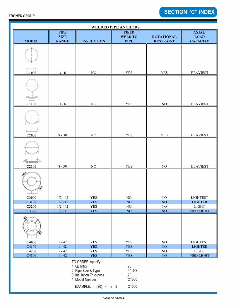
SECTION “C” INDEX
TO ORDER, specify:1. Quantity 202. Pipe Size & Type 4” IPS3. Insulation Thickness 2”4. Model Number C1000
EXAMPLE: (20) 4 x 2 C1000
PIPE FIELD AXIAL SIZE WELD TO ROTATIONAL LOAD
MODEL RANGE INSULATION PIPE RESTRAINT CAPACITY
C1000 3 - 6 NO YES YES HEAVIEST
C1100 3 - 6 NO YES NO HEAVIEST
C2000 8 - 30 NO YES YES HEAVIEST
C2100 8 - 30 NO YES NO HEAVIEST
C3000 1/2 - 42 YES NO NO LIGHTEST
C3100 1/2 - 42 YES NO NO LIGHTER
C3200 1/2 - 42 YES NO NO LIGHT
C3300 1/2 - 42 YES NO NO MED/LIGHT
C4000 1 - 42 YES YES NO LIGHTEST
C4100 1 - 42 YES YES NO LIGHTER
C4200 1 - 42 YES YES NO LIGHT
C4300 1 - 42 YES YES NO MED/LIGHT
WELDED PIPE ANCHORS
FRONEK GROUP
CATALOG PS-2004
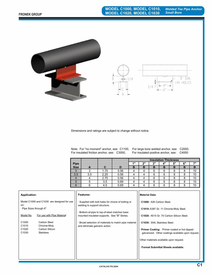
C1
Welded Tee Pipe AnchorSmall Bore
MODEL C1000, MODEL C1010,MODEL C1020, MODEL C1030
Application:
Model C1000 and C1030 are designed for use
on:
· Pipe Sizes through 6"
Model No. For use with Pipe Material
C1000 Carbon Steel
C1010 Chrome-Moly
C1020 Carbon Silicon
C1030 Stainless
Features:
· Supplied with bolt holes for choice of bolting or
welding to support structure.
· Bottom-of-pipe to top-of-steel matches base
mounted insulated supports. See "B" Series.
· Broad selection of materials to match pipe material
and eliminate galvanic action.
Material Data:
· C1000: A36 Carbon Steel.
· C1010: A387 Gr. 11 Chrome-Moly Steel.
· C1020: A515 Gr. 70 Carbon Silicon Steel.
· C1030: 304L Stainless Steel.
· Primer Coating: Primer coated or hot dipped
galvanized. Other coatings available upon request.
Other materials available upon request.
Formal Submittal Sheets available.
FRONEK GROUP
CATALOG PS-2004
Pipe 1" 2" 3" 4" 5" 6" 7"Size B B B B B B B
3 4 4 6 6 8 8 103.5 4 4 6 6 8 8 104 4 4 6 6 8 8 105 4 4 6 6 8 8 106 4 4 6 6 8 8 106 4.5 0.69
4 2.75 0.565 3.5 0.69
3 1.75 0.563.5 2.25 0.56
A C D
Note: For "no moment" anchor, see: C1100, For large bore welded anchor, see: C2000, For insulated friction anchor, see: C3000, For insulated positive anchor, see: C4000
Dimensions and ratings are subject to change without notice.
Insulation Thickness
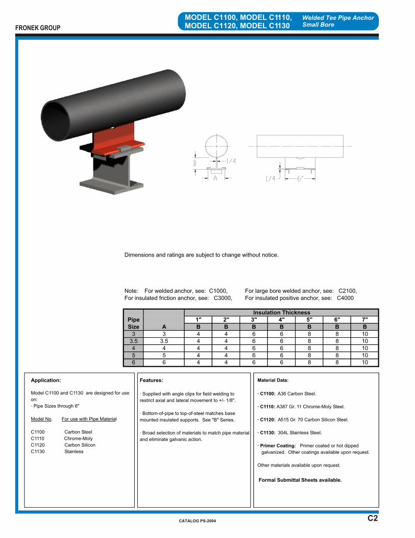
C2
Welded Tee Pipe AnchorSmall Bore
MODEL C1100, MODEL C1110,MODEL C1120, MODEL C1130
Application:
Model C1100 and C1130 are designed for use
on:
· Pipe Sizes through 6"
Model No. For use with Pipe Material
C1100 Carbon Steel
C1110 Chrome-Moly
C1120 Carbon Silicon
C1130 Stainless
Features:
· Supplied with angle clips for field welding to
restrict axial and lateral movement to +/- 1/8".
· Bottom-of-pipe to top-of-steel matches base
mounted insulated supports. See "B" Series.
· Broad selection of materials to match pipe material
and eliminate galvanic action.
Material Data:
· C1100: A36 Carbon Steel.
· C1110: A387 Gr. 11 Chrome-Moly Steel.
· C1120: A515 Gr. 70 Carbon Silicon Steel.
· C1130: 304L Stainless Steel.
· Primer Coating: Primer coated or hot dipped
galvanized. Other coatings available upon request.
Other materials available upon request.
Formal Submittal Sheets available.
FRONEK GROUP
CATALOG PS-2004
Pipe 1" 2" 3" 4" 5" 6" 7"Size B B B B B B B
3 4 4 6 6 8 8 103.5 4 4 6 6 8 8 104 4 4 6 6 8 8 105 4 4 6 6 8 8 106 4 4 6 6 8 8 10
Dimensions and ratings are subject to change without notice.
Insulation Thickness
Note: For welded anchor, see: C1000, For large bore welded anchor, see: C2100, For insulated friction anchor, see: C3000, For insulated positive anchor, see: C4000
33.5
A
6
45
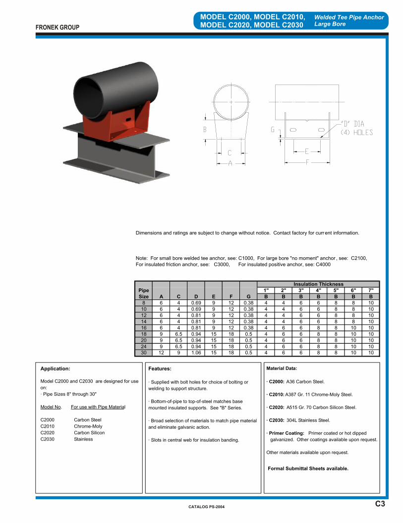
C3
Welded Tee Pipe AnchorLarge Bore
MODEL C2000, MODEL C2010,MODEL C2020, MODEL C2030
Application:
Model C2000 and C2030 are designed for use
on:
· Pipe Sizes 8" through 30"
Model No. For use with Pipe Material
C2000 Carbon Steel
C2010 Chrome-Moly
C2020 Carbon Silicon
C2030 Stainless
Features:
· Supplied with bolt holes for choice of bolting or
welding to support structure.
· Bottom-of-pipe to top-of-steel matches base
mounted insulated supports. See "B" Series.
· Broad selection of materials to match pipe material
and eliminate galvanic action.
· Slots in central web for insulation banding.
Material Data:
· C2000: A36 Carbon Steel.
· C2010: A387 Gr. 11 Chrome-Moly Steel.
· C2020: A515 Gr. 70 Carbon Silicon Steel.
· C2030: 304L Stainless Steel.
· Primer Coating: Primer coated or hot dipped
galvanized. Other coatings available upon request.
Other materials available upon request.
Formal Submittal Sheets available.
FRONEK GROUP
CATALOG PS-2004
Pipe 1" 2" 3" 4" 5" 6" 7"Size A C D E F G B B B B B B B
8 6 4 0.69 9 12 0.38 4 4 6 6 8 8 1010 6 4 0.69 9 12 0.38 4 4 6 6 8 8 1012 6 4 0.81 9 12 0.38 4 4 6 6 8 8 1014 6 4 0.81 9 12 0.38 4 4 6 6 8 8 1016 6 4 0.81 9 12 0.38 4 6 6 8 8 10 1018 9 6.5 0.94 15 18 0.5 4 6 6 8 8 10 1020 9 6.5 0.94 15 18 0.5 4 6 6 8 8 10 1024 9 6.5 0.94 15 18 0.5 4 6 6 8 8 10 1030 12 9 1.06 15 18 0.5 4 6 6 8 8 10 10
Dimensions and ratings are subject to change without notice. Contact factory for current information.
Insulation Thickness
Note: For small bore welded tee anchor, see: C1000, For large bore "no moment" anchor , see: C2100, For insulated friction anchor, see: C3000, For insulated positive anchor, see: C4000
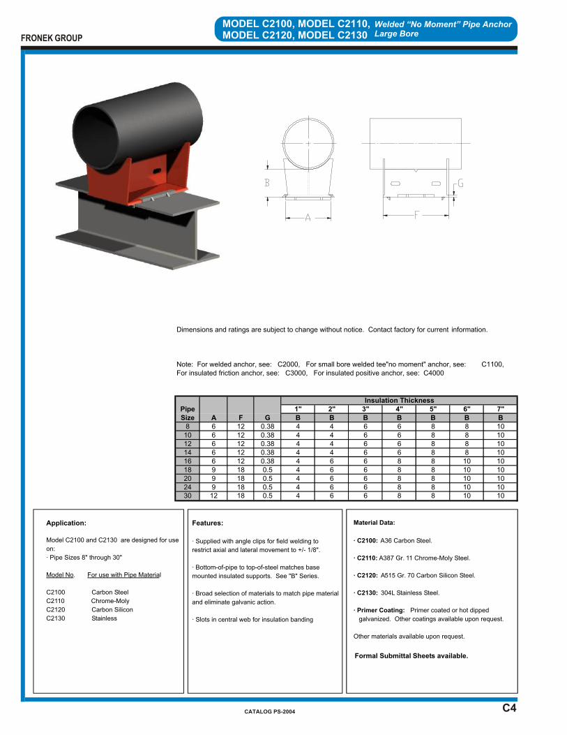
C4
Welded “No Moment” Pipe AnchorLarge Bore
MODEL C2100, MODEL C2110,MODEL C2120, MODEL C2130
Application:
Model C2100 and C2130 are designed for use
on:
· Pipe Sizes 8" through 30"
Model No. For use with Pipe Material
C2100 Carbon Steel
C2110 Chrome-Moly
C2120 Carbon Silicon
C2130 Stainless
Features:
· Supplied with angle clips for field welding to
restrict axial and lateral movement to +/- 1/8".
· Bottom-of-pipe to top-of-steel matches base
mounted insulated supports. See "B" Series.
· Broad selection of materials to match pipe material
and eliminate galvanic action.
· Slots in central web for insulation banding
Material Data:
· C2100: A36 Carbon Steel.
· C2110: A387 Gr. 11 Chrome-Moly Steel.
· C2120: A515 Gr. 70 Carbon Silicon Steel.
· C2130: 304L Stainless Steel.
· Primer Coating: Primer coated or hot dipped
galvanized. Other coatings available upon request.
Other materials available upon request.
Formal Submittal Sheets available.
FRONEK GROUP
CATALOG PS-2004
Pipe 1" 2" 3" 4" 5" 6" 7"Size A F G B B B B B B B
8 6 12 0.38 4 4 6 6 8 8 1010 6 12 0.38 4 4 6 6 8 8 1012 6 12 0.38 4 4 6 6 8 8 1014 6 12 0.38 4 4 6 6 8 8 1016 6 12 0.38 4 6 6 8 8 10 1018 9 18 0.5 4 6 6 8 8 10 1020 9 18 0.5 4 6 6 8 8 10 1024 9 18 0.5 4 6 6 8 8 10 1030 12 18 0.5 4 6 6 8 8 10 10
Insulation Thickness
Note: For welded anchor, see: C2000, For small bore welded tee"no moment" anchor, see: C1100, For insulated friction anchor, see: C3000, For insulated positive anchor, see: C4000
Dimensions and ratings are subject to change without notice. Contact factory for current information.
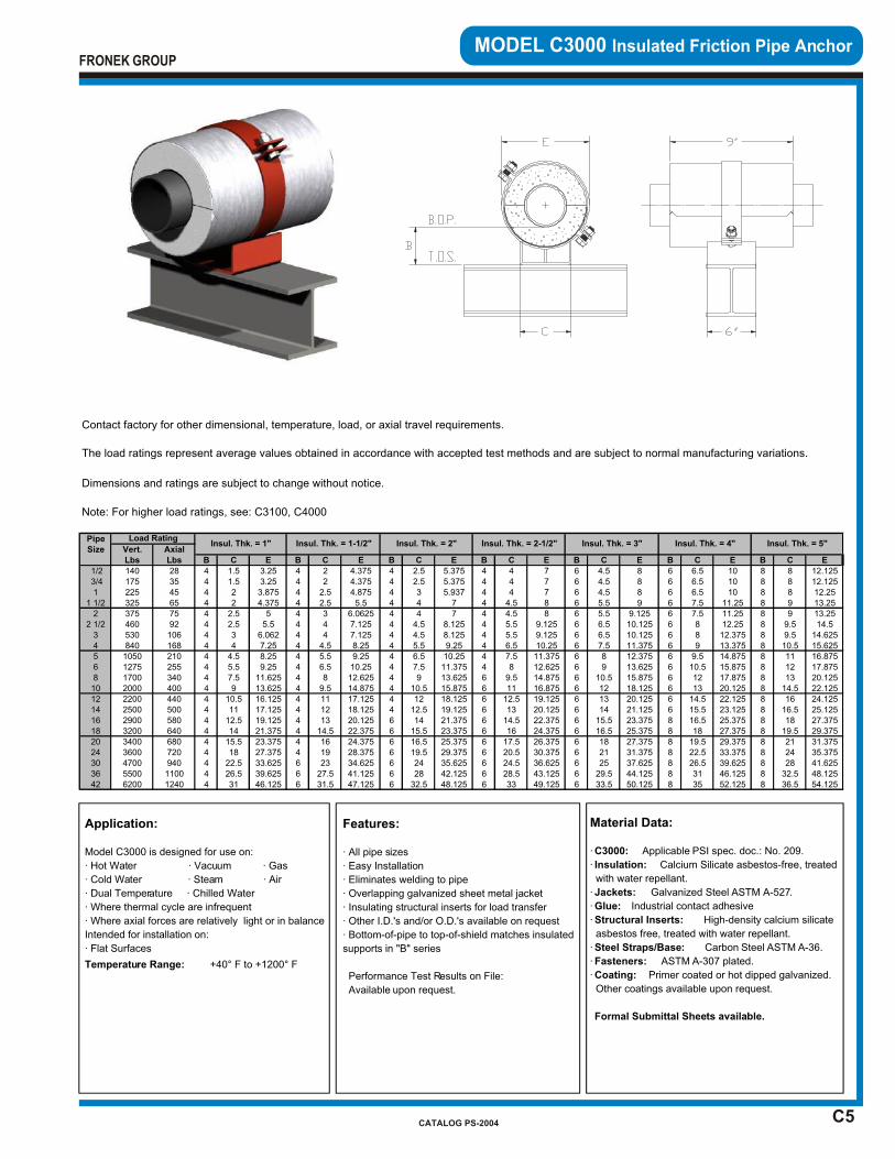
C5
MODEL C3000 Insulated Friction Pipe Anchor
Application:
Model C3000 is designed for use on:
· Hot Water · Vacuum · Gas
· Cold Water · Steam · Air
· Dual Temperature · Chilled Water
· Where thermal cycle are infrequent
· Where axial forces are relatively light or in balance
Intended for installation on:
· Flat Surfaces
Temperature Range: +40° F to +1200° F
Features:
· All pipe sizes
· Easy Installation
· Eliminates welding to pipe
· Overlapping galvanized sheet metal jacket
· Insulating structural inserts for load transfer
· Other I.D.'s and/or O.D.'s available on request
· Bottom-of-pipe to top-of-shield matches insulated
supports in "B" series
Performance Test Results on File:
Available upon request.
Material Data:
· C3000: Applicable PSI spec. doc.: No. 209.
· Insulation: Calcium Silicate asbestos-free, treated
with water repellant.
· Jackets: Galvanized Steel ASTM A-527.
· Glue: Industrial contact adhesive
· Structural Inserts: High-density calcium silicate
asbestos free, treated with water repellant.
· Steel Straps/Base: Carbon Steel ASTM A-36.
· Fasteners: ASTM A-307 plated.
· Coating: Primer coated or hot dipped galvanized.
Other coatings available upon request.
Formal Submittal Sheets available.
FRONEK GROUP
CATALOG PS-2004
Contact factory for other dimensional, temperature, load, or axial travel requirements.
The load ratings represent average values obtained in accordance with accepted test methods and are subject to normal manufacturing variations.
Dimensions and ratings are subject to change without notice.
Note: For higher load ratings, see: C3100, C4000
PipeSize Vert. Axial
Lbs Lbs B C E B C E B C E B C E B C E B C E B C E
1/2 140 28 4 1.5 3.25 4 2 4.375 4 2.5 5.375 4 4 7 6 4.5 8 6 6.5 10 8 8 12.125 3/4 175 35 4 1.5 3.25 4 2 4.375 4 2.5 5.375 4 4 7 6 4.5 8 6 6.5 10 8 8 12.1251 225 45 4 2 3.875 4 2.5 4.875 4 3 5.937 4 4 7 6 4.5 8 6 6.5 10 8 8 12.25
1 1/2 325 65 4 2 4.375 4 2.5 5.5 4 4 7 4 4.5 8 6 5.5 9 6 7.5 11.25 8 9 13.252 375 75 4 2.5 5 4 3 6.0625 4 4 7 4 4.5 8 6 5.5 9.125 6 7.5 11.25 8 9 13.25
2 1/2 460 92 4 2.5 5.5 4 4 7.125 4 4.5 8.125 4 5.5 9.125 6 6.5 10.125 6 8 12.25 8 9.5 14.53 530 106 4 3 6.062 4 4 7.125 4 4.5 8.125 4 5.5 9.125 6 6.5 10.125 6 8 12.375 8 9.5 14.6254 840 168 4 4 7.25 4 4.5 8.25 4 5.5 9.25 4 6.5 10.25 6 7.5 11.375 6 9 13.375 8 10.5 15.6255 1050 210 4 4.5 8.25 4 5.5 9.25 4 6.5 10.25 4 7.5 11.375 6 8 12.375 6 9.5 14.875 8 11 16.8756 1275 255 4 5.5 9.25 4 6.5 10.25 4 7.5 11.375 4 8 12.625 6 9 13.625 6 10.5 15.875 8 12 17.8758 1700 340 4 7.5 11.625 4 8 12.625 4 9 13.625 6 9.5 14.875 6 10.5 15.875 6 12 17.875 8 13 20.12510 2000 400 4 9 13.625 4 9.5 14.875 4 10.5 15.875 6 11 16.875 6 12 18.125 6 13 20.125 8 14.5 22.12512 2200 440 4 10.5 16.125 4 11 17.125 4 12 18.125 6 12.5 19.125 6 13 20.125 6 14.5 22.125 8 16 24.12514 2500 500 4 11 17.125 4 12 18.125 4 12.5 19.125 6 13 20.125 6 14 21.125 6 15.5 23.125 8 16.5 25.12516 2900 580 4 12.5 19.125 4 13 20.125 6 14 21.375 6 14.5 22.375 6 15.5 23.375 8 16.5 25.375 8 18 27.37518 3200 640 4 14 21.375 4 14.5 22.375 6 15.5 23.375 6 16 24.375 6 16.5 25.375 8 18 27.375 8 19.5 29.37520 3400 680 4 15.5 23.375 4 16 24.375 6 16.5 25.375 6 17.5 26.375 6 18 27.375 8 19.5 29.375 8 21 31.37524 3600 720 4 18 27.375 4 19 28.375 6 19.5 29.375 6 20.5 30.375 6 21 31.375 8 22.5 33.375 8 24 35.37530 4700 940 4 22.5 33.625 6 23 34.625 6 24 35.625 6 24.5 36.625 6 25 37.625 8 26.5 39.625 8 28 41.62536 5500 1100 4 26.5 39.625 6 27.5 41.125 6 28 42.125 6 28.5 43.125 6 29.5 44.125 8 31 46.125 8 32.5 48.12542 6200 1240 4 31 46.125 6 31.5 47.125 6 32.5 48.125 6 33 49.125 6 33.5 50.125 8 35 52.125 8 36.5 54.125
Insul. Thk. = 2-1/2" Insul. Thk. = 3" Insul. Thk. = 4" Insul. Thk. = 5"Load Rating
Insul. Thk. = 1" Insul. Thk. = 1-1/2" Insul. Thk. = 2"
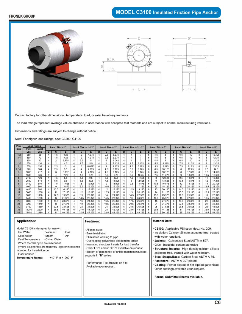
C6
MODEL C3100 Insulated Friction Pipe Anchor
Application:
Model C3100 is designed for use on:
· Hot Water · Vacuum · Gas
· Cold Water · Steam · Air
· Dual Temperature · Chilled Water
· Where thermal cycle are infrequent
· Where axial forces are relatively light or in balance
Intended for installation on:
· Flat Surfaces
Temperature Range: +40° F to +1200° F
Features:
· All pipe sizes
· Easy Installation
· Eliminates welding to pipe
· Overlapping galvanized sheet metal jacket
· Insulating structural inserts for load transfer
· Other I.D.'s and/or O.D.'s available on request
· Bottom-of-pipe to top-of-shield matches insulated
supports in "B" series
Performance Test Results on File:
Available upon request.
Material Data:
· C3100: Applicable PSI spec. doc.: No. 209.
· Insulation: Calcium Silicate asbestos-free, treated
with water repellant.
· Jackets: Galvanized Steel ASTM A-527.
· Glue: Industrial contact adhesive
· Structural Inserts: High-density calcium silicate
asbestos free, treated with water repellant.
· Steel Straps/Base: Carbon Steel ASTM A-36.
· Fasteners: ASTM A-307 plated.
· Coating: Primer coated or hot dipped galvanized.
Other coatings available upon request.
Formal Submittal Sheets available.
FRONEK GROUP
CATALOG PS-2004
Contact factory for other dimensional, temperature, load, or axial travel requirements.
The load ratings represent average values obtained in accordance with accepted test methods and are subject to normal manufacturing variations.
Dimensions and ratings are subject to change without notice.
Note: For higher load ratings, see: C3200, C4100
PipeSize Vert. Axial
Lbs Lbs B C E B C E B C E B C E B C E B C E B C E
1/2 280 56 4 1.5 3.25 4 2 4.375 4 2.5 5.375 4 4 7 6 4.5 8 6 6.5 10 8 8 12.125 3/4 350 70 4 1.5 3.25 4 2 4.375 4 2.5 5.375 4 4 7 6 4.5 8 6 6.5 10 8 8 12.251 450 90 4 2 3.875 4 2.5 5 4 3 6.062 4 4 7 6 4.5 8 6 6.5 10 8 8 12.25
1 1/2 650 130 4 2 4.5 4 2.5 5.5 4 4 7.125 4 4.5 8.125 6 5.5 9.125 6 7.5 11.25 8 9 13.252 750 150 4 2.5 5 4 3 6.0625 4 4 7.125 4 4.5 8.125 6 5.5 9.125 6 7.5 11.25 8 9 13.25
2 1/2 920 184 4 2.5 5.5 4 4 7.125 4 4.5 8.125 4 5.5 9.125 6 6.5 10.125 6 8 12.25 8 9.5 14.53 1060 212 4 3 6.187 4 4 7.125 4 4.5 8.125 4 5.5 9.125 6 6.5 10.125 6 8 12.375 8 9.5 14.6254 1680 336 4 4 7.25 4 4.5 8.25 4 5.5 9.25 4 6.5 10.25 6 7.5 11.375 6 9 13.375 8 10.5 15.6255 2100 420 4 4.5 8.5 4 5.5 9.5 4 6.5 10.5 4 7.5 11.625 6 8 12.625 6 9.5 14.875 8 11 16.8756 2550 510 4 5.5 9.5 4 6.5 10.5 4 7.5 11.625 4 8 12.625 6 9 13.625 6 10.5 15.875 8 12 17.8758 3400 680 4 7.5 11.625 4 8 12.625 4 9 13.625 6 9.5 14.875 6 10.5 15.875 6 12 18.125 8 13 20.12510 4000 800 4 9 13.875 4 9.5 15.125 4 10.5 16.125 6 11 17.125 6 12 18.125 6 13 20.125 8 14.5 22.12512 4400 880 4 10.5 16.125 4 11 17.125 4 12 18.125 6 12.5 19.125 6 13 20.125 6 14.5 22.125 8 16 24.12514 5000 1000 4 11 17.125 4 12 18.125 4 12.5 19.125 6 13 20.125 6 14 21.125 6 15.5 23.125 8 16.5 25.12516 5800 1160 4 12.5 19.375 4 13 20.375 6 14 21.375 6 14.5 22.375 6 15.5 23.375 8 16.5 25.375 8 18 27.37518 6400 1280 4 14 21.375 4 14.5 22.375 6 15.5 23.375 6 16 24.375 6 16.5 25.375 8 18 27.375 8 19.5 29.37520 6800 1360 4 15.5 23.375 4 16 24.375 6 16.5 25.375 6 17.5 26.375 6 18 27.375 8 19.5 29.375 8 21 31.37524 7200 1440 4 18 27.375 4 19 28.375 6 19.5 29.375 6 20.5 30.375 6 21 31.375 8 22.5 33.375 8 24 35.37530 9400 1880 4 22.5 33.625 6 23 34.625 6 24 35.625 6 24.5 36.625 6 25 37.625 8 26.5 39.625 8 28 41.62536 11000 2200 4 26.5 40.125 6 27.5 41.125 6 28 42.125 6 28.5 43.125 6 29.5 44.125 8 31 46.125 8 32.5 48.12542 12400 2480 4 31 46.125 6 31.5 47.125 6 32.5 48.125 6 33 49.125 6 33.5 50.125 8 35 52.125 8 36.5 54.125
Insul. Thk. = 2-1/2" Insul. Thk. = 3" Insul. Thk. = 4" Insul. Thk. = 5"Load Rating
Insul. Thk. = 1" Insul. Thk. = 1-1/2" Insul. Thk. = 2"

C7
MODEL C3200 Insulated Friction Pipe Anchor
Material Data:
· C3200: Applicable PSI spec. doc.: No. 209.
· Insulation: Calcium Silicate asbestos-free, treated
with water repellant.
· Jackets: Galvanized Steel ASTM A-527.
· Glue: Industrial contact adhesive
· Structural Inserts: High-density calcium silicate
asbestos free, treated with water repellant.
· Steel Straps/Base: Carbon Steel ASTM A-36.
· Fasteners: ASTM A-307 plated.
· Coating: Primer coated or hot dipped galvanized.
Other coatings available upon request.
Formal Submittal Sheets available.
Application:
Model C3200 is designed for use on:
· Hot Water · Vacuum · Gas
· Cold Water · Steam · Air
· Dual Temperature · Chilled Water
· Where thermal cycle are infrequent
· Where axial forces are relatively light or in balance
Intended for installation on:
· Flat Surfaces
Temperature Range: +40° F to +1200° F
Features:
· All pipe sizes
· Easy Installation
· Eliminates welding to pipe
· Overlapping galvanized sheet metal jacket
· Insulating structural inserts for load transfer
· Other I.D.'s and/or O.D.'s available on request
· Bottom-of-pipe to top-of-shield matches insulated
supports in "B" series
Performance Test Results on File:
Available upon request.
FRONEK GROUP
CATALOG PS-2004
Contact factory for other dimensional, temperature, load, or axial travel requirements.
The load ratings represent average values obtained in accordance with accepted test methods and are subject to normal manufacturing variations.
Dimensions and ratings are subject to change without notice.
Note: For higher load ratings, see: C3300, C4200
PipeSize Vert. Axial
Lbs Lbs B C E B C E B C E B C E B C E B C E B C E
1/2 400 80 4 1.5 3.25 4 2 4.375 4 2.5 5.375 4 4 7 6 4.5 8 6 6.5 10 8 8 12.125 3/4 500 100 4 1.5 3.25 4 2 4.375 4 2.5 5.375 4 4 7 6 4.5 8 6 6.5 10 8 8 12.251 650 130 4 2 4 4 2.5 5 4 3 6.062 4 4 7.125 6 4.5 8.125 6 6.5 10.125 8 8 12.25
1 1/2 950 190 4 2 4.5 4 2.5 5.5 4 4 7.125 4 4.5 8.125 6 5.5 9.125 6 7.5 11.25 8 9 13.252 1100 220 4 2.5 5 4 3 6.1875 4 4 7.125 4 4.5 8.125 6 5.5 9.125 6 7.5 11.25 8 9 13.25
2 1/2 1350 270 4 2.5 5.5 4 4 7.125 4 4.5 8.125 4 5.5 9.125 6 6.5 10.125 6 8 12.25 8 9.5 14.53 1600 320 4 3 6.187 4 4 7.125 4 4.5 8.125 4 5.5 9.125 6 6.5 10.125 6 8 12.375 8 9.5 14.6254 2500 500 4 4 7.25 4 4.5 8.25 4 5.5 9.25 4 6.5 10.25 6 7.5 11.375 6 9 13.375 8 10.5 15.6255 3100 620 4 4.5 8.5 4 5.5 9.5 4 6.5 10.5 4 7.5 11.625 6 8 12.625 6 9.5 14.875 8 11 16.8756 3800 760 4 5.5 9.5 4 6.5 10.5 4 7.5 11.625 4 8 12.625 6 9 13.625 6 10.5 15.875 8 12 17.8758 5100 1020 4 7.5 11.625 4 8 12.625 4 9 13.625 6 9.5 14.875 6 10.5 15.875 6 12 18.125 8 13 20.12510 6000 1200 4 9 13.875 4 9.5 15.125 4 10.5 16.125 6 11 17.125 6 12 18.125 6 13 20.125 8 14.5 22.12512 6600 1320 4 10.5 16.125 4 11 17.125 4 12 18.125 6 12.5 19.125 6 13 20.125 6 14.5 22.125 8 16 24.12514 7500 1500 4 11 17.125 4 12 18.125 4 12.5 19.125 6 13 20.125 6 14 21.125 6 15.5 23.125 8 16.5 25.12516 8700 1740 4 12.5 19.375 4 13 20.375 6 14 21.375 6 14.5 22.375 6 15.5 23.375 8 16.5 25.375 8 18 27.37518 9600 1920 4 14 21.375 4 14.5 22.375 6 15.5 23.375 6 16 24.375 6 16.5 25.375 8 18 27.375 8 19.5 29.37520 10200 2040 4 15.5 23.375 4 16 24.375 6 16.5 25.375 6 17.5 26.375 6 18 27.375 8 19.5 29.375 8 21 31.37524 10800 2160 4 18 27.375 4 19 28.375 6 19.5 29.375 6 20.5 30.375 6 21 31.375 8 22.5 33.375 8 24 35.37530 14100 2820 4 22.5 33.625 6 23 34.625 6 24 35.625 6 24.5 36.625 6 25 37.625 8 26.5 39.625 8 28 41.62536 16500 3300 4 26.5 40.125 6 27.5 41.125 6 28 42.125 6 28.5 43.125 6 29.5 44.125 8 31 46.125 8 32.5 48.12542 18600 3720 4 31 46.125 6 31.5 47.125 6 32.5 48.125 6 33 49.125 6 33.5 50.125 8 35 52.125 8 36.5 54.125
Load RatingInsul. Thk. = 1" Insul. Thk. = 1-1/2" Insul. Thk. = 2" Insul. Thk. = 2-1/2" Insul. Thk. = 3" Insul. Thk. = 4" Insul. Thk. = 5"

C8
MODEL C3300 Insulated Friction Pipe Anchor
Material Data:
· C3300: Applicable PSI spec. doc.: No. 209.
· Insulation: Calcium Silicate asbestos-free, treated
with water repellant.
· Jackets: Galvanized Steel ASTM A-527.
· Glue: Industrial contact adhesive
· Structural Inserts: High-density calcium silicate
asbestos free, treated with water repellant.
· Steel Straps/Base: Carbon Steel ASTM A-36.
· Fasteners: ASTM A-307 plated.
· Coating: Primer coated or hot dipped galvanized.
Other coatings available upon request.
Formal Submittal Sheets available.
Application:
Model C3300 is designed for use on:
· Hot Water · Vacuum · Gas
· Cold Water · Steam · Air
· Dual Temperature · Chilled Water
· Where thermal cycle are infrequent
· Where axial forces are relatively light or in balance Intended for installation on:
· Flat Surfaces
Temperature Range: +40° F to +1200° F
Features:
· All pipe sizes
· Easy Installation
· Eliminates welding to pipe
· Overlapping galvanized sheet metal jacket
· Insulating structural inserts for load transfer
· Other I.D.'s and/or O.D.'s available on request
· Bottom-of-pipe to top-of-shield matches insulated
supports in "B" series
Performance Test Results on File:
Available upon request.
FRONEK GROUP
CATALOG PS-2004
Contact factory for other dimensional, temperature, load, or axial travel requirements.
The load ratings represent average values obtained in accordance with accepted test methods and are subject to normal manufacturing variations.
Dimensions and ratings are subject to change without notice.
Note: For higher load ratings, see: C4300
PipeSize Vert. Axial
Lbs Lbs B C E B C E B C E B C E B C E B C E B C E
1/2 550 110 4 1.5 3.375 4 2 4.5 4 2.5 5.5 4 4 7.125 6 4.5 8.125 6 6.5 10.125 8 8 12.25 3/4 700 140 4 1.5 3.375 4 2 4.5 4 2.5 5.5 4 4 7.125 6 4.5 8.125 6 6.5 10.125 8 8 12.251 900 180 4 2 4 4 2.5 5 4 3 6.062 4 4 7.125 6 4.5 8.125 6 6.5 10.125 8 8 12.25
1 1/2 1300 260 4 2 4.5 4 2.5 5.5 4 4 7.125 4 4.5 8.125 6 5.5 9.125 6 7.5 11.25 8 9 13.252 1500 300 4 2.5 5 4 3 6.0625 4 4 7.125 4 4.5 8.125 6 5.5 9.125 6 7.5 11.25 8 9 13.25
2 1/2 1800 360 4 2.5 5.5 4 4 7.125 4 4.5 8.125 4 5.5 9.125 6 6.5 10.125 6 8 12.375 8 9.5 14.6253 2100 420 4 3 6.187 4 4 7.125 4 4.5 8.125 4 5.5 9.125 6 6.5 10.125 6 8 12.375 8 9.5 14.6254 3350 670 4 4 7.25 4 4.5 8.25 4 5.5 9.25 4 6.5 10.25 6 7.5 11.375 6 9 13.375 8 10.5 15.6255 4200 840 4 4.5 8.5 4 5.5 9.5 4 6.5 10.5 4 7.5 11.625 6 8 12.625 6 9.5 14.875 8 11 16.8756 5100 1020 4 5.5 9.5 4 6.5 10.5 4 7.5 11.625 4 8 12.625 6 9 13.625 6 10.5 15.875 8 12 17.8758 6800 1360 4 7.5 11.625 4 8 12.625 4 9 13.625 6 9.5 14.875 6 10.5 15.875 6 12 18.125 8 13 20.12510 8000 1600 4 9 13.875 4 9.5 15.125 4 10.5 16.125 6 11 17.125 6 12 18.125 6 13 20.125 8 14.5 22.12512 8800 1760 4 10.5 16.125 4 11 17.125 4 12 18.125 6 12.5 19.125 6 13 20.125 6 14.5 22.125 8 16 24.12514 10000 2000 4 11 17.125 4 12 18.125 4 12.5 19.125 6 13 20.125 6 14 21.125 6 15.5 23.125 8 16.5 25.12516 11600 2320 4 12.5 19.375 4 13 20.375 6 14 21.375 6 14.5 22.375 6 15.5 23.375 8 16.5 25.375 8 18 27.37518 12800 2560 4 14 21.375 4 14.5 22.375 6 15.5 23.375 6 16 24.375 6 16.5 25.375 8 18 27.375 8 19.5 29.37520 13600 2720 4 15.5 23.375 4 16 24.375 6 16.5 25.375 6 17.5 26.375 6 18 27.375 8 19.5 29.375 8 21 31.37524 14400 2880 4 18 27.375 4 19 28.375 6 19.5 29.375 6 20.5 30.375 6 21 31.375 8 22.5 33.375 8 24 35.37530 18800 3760 4 22.5 33.625 6 23 34.625 6 24 35.625 6 24.5 36.625 6 25 37.625 8 26.5 39.625 8 28 41.62536 22000 4400 4 26.5 40.125 6 27.5 41.125 6 28 42.125 6 28.5 43.125 6 29.5 44.125 8 31 46.125 8 32.5 48.12542 24800 4960 4 31 46.125 6 31.5 47.125 6 32.5 48.125 6 33 49.125 6 33.5 50.125 8 35 52.125 8 36.5 54.125
Load RatingInsul. Thk. = 1" Insul. Thk. = 1-1/2" Insul. Thk. = 2" Insul. Thk. = 2-1/2" Insul. Thk. = 3" Insul. Thk. = 4" Insul. Thk. = 5"
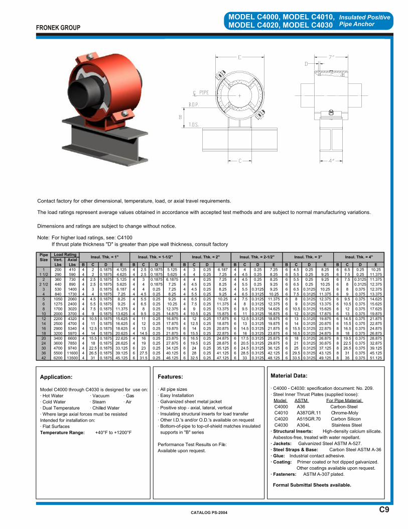
C9
Insulated Positive Pipe Anchor
MODEL C4000, MODEL C4010,MODEL C4020, MODEL C4030
Application:
Model C4000 through C4030 is designed for use on:
· Hot Water · Vacuum · Gas
· Cold Water · Steam · Air
· Dual Temperature · Chilled Water
· Where large axial forces must be resisted
Intended for installation on:
· Flat Surfaces
Temperature Range: +40°F to +1200°F
Features:
· All pipe sizes
· Easy Installation
· Galvanized sheet metal jacket
· Positive stop - axial, lateral, vertical
· Insulating structural inserts for load transfer
· Other I.D.'s and/or O.D.'s available on request
· Bottom-of-pipe to top-of-shield matches insulated
supports in "B" series
Performance Test Results on File:
Available upon request.
Material Data:
· C4000 - C4030: specification document: No. 209.
· Steel Inner Thrust Plates (supplied loose):
Model ASTM For Pipe Material
C4000 A36 Carbon-Steel
C4010 A387GR.11 Chrome-Moly
C4020 A515GR.70 Carbon Silicon
C4030 A304L Stainless Steel
· Structural Inserts: High-density calcium silicate.
Asbestos-free, treated with water repellant.
· Jackets: Galvanized Steel ASTM A-527.
· Steel Straps & Base: Carbon Steel ASTM A-36
· Glue: Industrial contact adhesive.
· Coating: Primer coated or hot dipped galvanized.
Other coatings available upon request.
· Fasteners: ASTM A-307 plated.
Formal Submittal Sheets available.
FRONEK GROUP
CATALOG PS-2004
Contact factory for other dimensional, temperature, load, or axial travel requirements.
The load ratings represent average values obtained in accordance with accepted test methods and are subject to normal manufacturing variations.
Dimensions and ratings are subject to change without notice.
Note: For higher load ratings, see: C4100
If thrust plate thickness "D" is greater than pipe wall thickness, consult factory
PipeSize Vert. Axial
Lbs Lbs B C D E B C D E B C D E B C D E B C D E B C D E
1 200 410 4 2 0.1875 4.125 4 2.5 0.1875 5.125 4 3 0.25 6.187 4 4 0.25 7.25 6 4.5 0.25 8.25 6 6.5 0.25 10.251 1/2 290 590 4 2 0.1875 4.625 4 2.5 0.1875 5.625 4 4 0.25 7.25 4 4.5 0.25 8.25 6 5.5 0.25 9.25 6 7.5 0.25 11.375
2 360 730 4 2.5 0.1875 5.125 4 3 0.1875 6.1875 4 4 0.25 7.25 4 4.5 0.25 8.25 6 5.5 0.25 9.25 6 7.5 0.3125 11.3752 1/2 440 890 4 2.5 0.1875 5.625 4 4 0.1875 7.25 4 4.5 0.25 8.25 4 5.5 0.25 9.25 6 6.5 0.25 10.25 6 8 0.3125 12.375
3 530 1400 4 3 0.1875 6.187 4 4 0.25 7.25 4 4.5 0.25 8.25 4 5.5 0.3125 9.25 6 6.5 0.3125 10.25 6 8 0.375 12.3754 840 1730 4 4 0.1875 7.25 4 4.5 0.25 8.25 4 5.5 0.25 9.25 4 6.5 0.3125 10.25 6 7.5 0.3125 11.375 6 9 0.375 13.3755 1050 2060 4 4.5 0.1875 8.25 4 5.5 0.25 9.25 4 6.5 0.25 10.25 4 7.5 0.3125 11.375 6 8 0.3125 12.375 6 9.5 0.375 14.6256 1275 2400 4 5.5 0.1875 9.25 4 6.5 0.25 10.25 4 7.5 0.25 11.375 4 8 0.3125 12.375 6 9 0.3125 13.375 6 10.5 0.375 15.6258 1700 3020 4 7.5 0.1875 11.375 4 8 0.25 12.375 4 9 0.25 13.375 6 9.5 0.3125 14.625 6 10.5 0.3125 15.625 6 12 0.375 17.62510 2000 3700 4 9 0.1875 13.625 4 9.5 0.25 14.875 4 10.5 0.25 15.875 6 11 0.3125 16.875 6 12 0.3125 17.875 6 13 0.375 19.87512 2200 4320 4 10.5 0.1875 15.625 4 11 0.25 16.875 4 12 0.25 17.875 6 12.5 0.3125 18.875 6 13 0.3125 19.875 6 14.5 0.375 21.87514 2500 4700 4 11 0.1875 16.625 4 12 0.25 17.875 4 12.5 0.25 18.875 6 13 0.3125 19.875 6 14 0.3125 20.875 6 15.5 0.375 22.87516 2900 5340 4 12.5 0.1875 18.625 4 13 0.25 19.875 6 14 0.25 20.875 6 14.5 0.3125 21.875 6 15.5 0.3125 22.875 8 16.5 0.375 24.87518 3200 5970 4 14 0.1875 20.625 4 14.5 0.25 21.875 6 15.5 0.25 22.875 6 16 0.3125 23.875 6 16.5 0.3125 24.875 8 18 0.375 26.87520 3400 6600 4 15.5 0.1875 22.625 4 16 0.25 23.875 6 16.5 0.25 24.875 6 17.5 0.3125 25.875 6 18 0.3125 26.875 8 19.5 0.375 28.87524 3600 7850 4 18 0.1875 26.625 4 19 0.25 27.875 6 19.5 0.25 28.875 6 20.5 0.3125 29.875 6 21 0.3125 30.875 8 22.5 0.375 32.87530 4700 9740 4 22.5 0.1875 33.125 6 23 0.25 34.125 6 24 0.25 35.125 6 24.5 0.3125 36.125 6 25 0.3125 37.125 8 26.5 0.375 39.12536 5500 11600 4 26.5 0.1875 39.125 6 27.5 0.25 40.125 6 28 0.25 41.125 6 28.5 0.3125 42.125 6 29.5 0.3125 43.125 8 31 0.375 45.12542 6200 13500 4 31 0.1875 45.125 6 31.5 0.25 46.125 6 32.5 0.25 47.125 6 33 0.3125 48.125 6 33.5 0.3125 49.125 8 35 0.375 51.125
Insul. Thk. = 2-1/2" Insul. Thk. = 3" Insul. Thk. = 4"Load Rating
Insul. Thk. = 1" Insul. Thk. = 1-1/2" Insul. Thk. = 2"
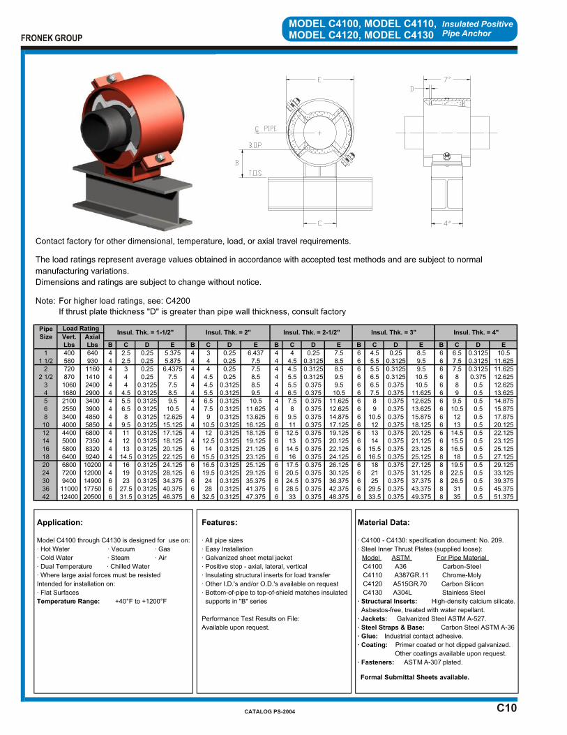
C10
Insulated Positive Pipe Anchor
MODEL C4100, MODEL C4110,MODEL C4120, MODEL C4130
Application:
Model C4100 through C4130 is designed for use on:
· Hot Water · Vacuum · Gas
· Cold Water · Steam · Air
· Dual Temperature · Chilled Water
· Where large axial forces must be resisted
Intended for installation on:
· Flat Surfaces
Temperature Range: +40°F to +1200°F
Features:
· All pipe sizes
· Easy Installation
· Galvanized sheet metal jacket
· Positive stop - axial, lateral, vertical
· Insulating structural inserts for load transfer
· Other I.D.'s and/or O.D.'s available on request
· Bottom-of-pipe to top-of-shield matches insulated
supports in "B" series
Performance Test Results on File:
Available upon request.
Material Data:
· C4100 - C4130: specification document: No. 209.
· Steel Inner Thrust Plates (supplied loose):
Model ASTM For Pipe Material
C4100 A36 Carbon-Steel
C4110 A387GR.11 Chrome-Moly
C4120 A515GR.70 Carbon Silicon
C4130 A304L Stainless Steel
· Structural Inserts: High-density calcium silicate.
Asbestos-free, treated with water repellant.
· Jackets: Galvanized Steel ASTM A-527.
· Steel Straps & Base: Carbon Steel ASTM A-36
· Glue: Industrial contact adhesive.
· Coating: Primer coated or hot dipped galvanized.
Other coatings available upon request.
· Fasteners: ASTM A-307 plated.
Formal Submittal Sheets available.
FRONEK GROUP
CATALOG PS-2004
Contact factory for other dimensional, temperature, load, or axial travel requirements.
The load ratings represent average values obtained in accordance with accepted test methods and are subject to normal
manufacturing variations.
Dimensions and ratings are subject to change without notice.
Note: For higher load ratings, see: C4200
If thrust plate thickness "D" is greater than pipe wall thickness, consult factory
PipeSize Vert. Axial
Lbs Lbs B C D E B C D E B C D E B C D E B C D E
1 400 640 4 2.5 0.25 5.375 4 3 0.25 6.437 4 4 0.25 7.5 6 4.5 0.25 8.5 6 6.5 0.3125 10.51 1/2 580 930 4 2.5 0.25 5.875 4 4 0.25 7.5 4 4.5 0.3125 8.5 6 5.5 0.3125 9.5 6 7.5 0.3125 11.625
2 720 1160 4 3 0.25 6.4375 4 4 0.25 7.5 4 4.5 0.3125 8.5 6 5.5 0.3125 9.5 6 7.5 0.3125 11.6252 1/2 870 1410 4 4 0.25 7.5 4 4.5 0.25 8.5 4 5.5 0.3125 9.5 6 6.5 0.3125 10.5 6 8 0.375 12.625
3 1060 2400 4 4 0.3125 7.5 4 4.5 0.3125 8.5 4 5.5 0.375 9.5 6 6.5 0.375 10.5 6 8 0.5 12.6254 1680 2900 4 4.5 0.3125 8.5 4 5.5 0.3125 9.5 4 6.5 0.375 10.5 6 7.5 0.375 11.625 6 9 0.5 13.6255 2100 3400 4 5.5 0.3125 9.5 4 6.5 0.3125 10.5 4 7.5 0.375 11.625 6 8 0.375 12.625 6 9.5 0.5 14.8756 2550 3900 4 6.5 0.3125 10.5 4 7.5 0.3125 11.625 4 8 0.375 12.625 6 9 0.375 13.625 6 10.5 0.5 15.8758 3400 4850 4 8 0.3125 12.625 4 9 0.3125 13.625 6 9.5 0.375 14.875 6 10.5 0.375 15.875 6 12 0.5 17.87510 4000 5850 4 9.5 0.3125 15.125 4 10.5 0.3125 16.125 6 11 0.375 17.125 6 12 0.375 18.125 6 13 0.5 20.12512 4400 6800 4 11 0.3125 17.125 4 12 0.3125 18.125 6 12.5 0.375 19.125 6 13 0.375 20.125 6 14.5 0.5 22.12514 5000 7350 4 12 0.3125 18.125 4 12.5 0.3125 19.125 6 13 0.375 20.125 6 14 0.375 21.125 6 15.5 0.5 23.12516 5800 8320 4 13 0.3125 20.125 6 14 0.3125 21.125 6 14.5 0.375 22.125 6 15.5 0.375 23.125 8 16.5 0.5 25.12518 6400 9240 4 14.5 0.3125 22.125 6 15.5 0.3125 23.125 6 16 0.375 24.125 6 16.5 0.375 25.125 8 18 0.5 27.12520 6800 10200 4 16 0.3125 24.125 6 16.5 0.3125 25.125 6 17.5 0.375 26.125 6 18 0.375 27.125 8 19.5 0.5 29.12524 7200 12000 4 19 0.3125 28.125 6 19.5 0.3125 29.125 6 20.5 0.375 30.125 6 21 0.375 31.125 8 22.5 0.5 33.12530 9400 14900 6 23 0.3125 34.375 6 24 0.3125 35.375 6 24.5 0.375 36.375 6 25 0.375 37.375 8 26.5 0.5 39.37536 11000 17750 6 27.5 0.3125 40.375 6 28 0.3125 41.375 6 28.5 0.375 42.375 6 29.5 0.375 43.375 8 31 0.5 45.37542 12400 20500 6 31.5 0.3125 46.375 6 32.5 0.3125 47.375 6 33 0.375 48.375 6 33.5 0.375 49.375 8 35 0.5 51.375
Insul. Thk. = 3" Insul. Thk. = 4"Load Rating
Insul. Thk. = 1-1/2" Insul. Thk. = 2" Insul. Thk. = 2-1/2"
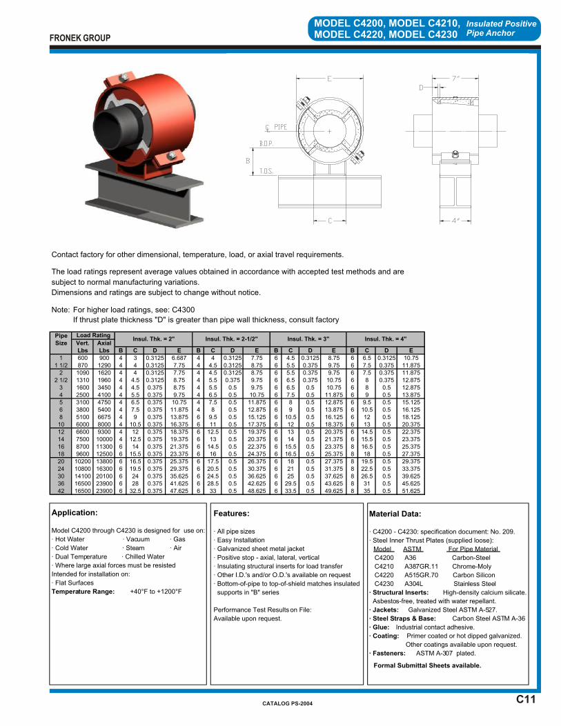
C11
Insulated Positive Pipe Anchor
MODEL C4200, MODEL C4210,MODEL C4220, MODEL C4230
Application:
Model C4200 through C4230 is designed for use on:
· Hot Water · Vacuum · Gas
· Cold Water · Steam · Air
· Dual Temperature · Chilled Water
· Where large axial forces must be resisted
Intended for installation on:
· Flat Surfaces
Temperature Range: +40°F to +1200°F
Features:
· All pipe sizes
· Easy Installation
· Galvanized sheet metal jacket
· Positive stop - axial, lateral, vertical
· Insulating structural inserts for load transfer
· Other I.D.'s and/or O.D.'s available on request
· Bottom-of-pipe to top-of-shield matches insulated
supports in "B" series
Performance Test Results on File:
Available upon request.
Material Data:
· C4200 - C4230: specification document: No. 209.
· Steel Inner Thrust Plates (supplied loose):
Model ASTM For Pipe Material
C4200 A36 Carbon-Steel
C4210 A387GR.11 Chrome-Moly
C4220 A515GR.70 Carbon Silicon
C4230 A304L Stainless Steel
· Structural Inserts: High-density calcium silicate.
Asbestos-free, treated with water repellant.
· Jackets: Galvanized Steel ASTM A-527.
· Steel Straps & Base: Carbon Steel ASTM A-36
· Glue: Industrial contact adhesive.
· Coating: Primer coated or hot dipped galvanized.
Other coatings available upon request.
· Fasteners: ASTM A-307 plated.
Formal Submittal Sheets available.
FRONEK GROUP
CATALOG PS-2004
Contact factory for other dimensional, temperature, load, or axial travel requirements.
The load ratings represent average values obtained in accordance with accepted test methods and are
subject to normal manufacturing variations.
Dimensions and ratings are subject to change without notice.
Note: For higher load ratings, see: C4300
If thrust plate thickness "D" is greater than pipe wall thickness, consult factory
PipeSize Vert. Axial
Lbs Lbs B C D E B C D E B C D E B C D E
1 600 900 4 3 0.3125 6.687 4 4 0.3125 7.75 6 4.5 0.3125 8.75 6 6.5 0.3125 10.751 1/2 870 1290 4 4 0.3125 7.75 4 4.5 0.3125 8.75 6 5.5 0.375 9.75 6 7.5 0.375 11.875
2 1090 1620 4 4 0.3125 7.75 4 4.5 0.3125 8.75 6 5.5 0.375 9.75 6 7.5 0.375 11.8752 1/2 1310 1960 4 4.5 0.3125 8.75 4 5.5 0.375 9.75 6 6.5 0.375 10.75 6 8 0.375 12.875
3 1600 3450 4 4.5 0.375 8.75 4 5.5 0.5 9.75 6 6.5 0.5 10.75 6 8 0.5 12.8754 2500 4100 4 5.5 0.375 9.75 4 6.5 0.5 10.75 6 7.5 0.5 11.875 6 9 0.5 13.8755 3100 4750 4 6.5 0.375 10.75 4 7.5 0.5 11.875 6 8 0.5 12.875 6 9.5 0.5 15.1256 3800 5400 4 7.5 0.375 11.875 4 8 0.5 12.875 6 9 0.5 13.875 6 10.5 0.5 16.1258 5100 6675 4 9 0.375 13.875 6 9.5 0.5 15.125 6 10.5 0.5 16.125 6 12 0.5 18.12510 6000 8000 4 10.5 0.375 16.375 6 11 0.5 17.375 6 12 0.5 18.375 6 13 0.5 20.37512 6600 9300 4 12 0.375 18.375 6 12.5 0.5 19.375 6 13 0.5 20.375 6 14.5 0.5 22.37514 7500 10000 4 12.5 0.375 19.375 6 13 0.5 20.375 6 14 0.5 21.375 6 15.5 0.5 23.37516 8700 11300 6 14 0.375 21.375 6 14.5 0.5 22.375 6 15.5 0.5 23.375 8 16.5 0.5 25.37518 9600 12500 6 15.5 0.375 23.375 6 16 0.5 24.375 6 16.5 0.5 25.375 8 18 0.5 27.37520 10200 13800 6 16.5 0.375 25.375 6 17.5 0.5 26.375 6 18 0.5 27.375 8 19.5 0.5 29.37524 10800 16300 6 19.5 0.375 29.375 6 20.5 0.5 30.375 6 21 0.5 31.375 8 22.5 0.5 33.37530 14100 20100 6 24 0.375 35.625 6 24.5 0.5 36.625 6 25 0.5 37.625 8 26.5 0.5 39.62536 16500 23900 6 28 0.375 41.625 6 28.5 0.5 42.625 6 29.5 0.5 43.625 8 31 0.5 45.62542 16500 23900 6 32.5 0.375 47.625 6 33 0.5 48.625 6 33.5 0.5 49.625 8 35 0.5 51.625
Insul. Thk. = 4"Load Rating
Insul. Thk. = 2" Insul. Thk. = 2-1/2" Insul. Thk. = 3"
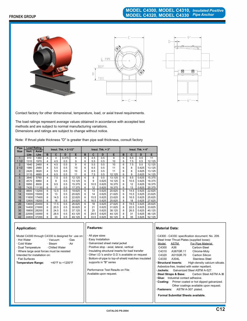
C12
Insulated Positive Pipe Anchor
MODEL C4300, MODEL C4310,MODEL C4320, MODEL C4330
Application:
Model C4300 through C4330 is designed for use on:
· Hot Water · Vacuum · Gas
· Cold Water · Steam · Air
· Dual Temperature · Chilled Water
· Where large axial forces must be resisted
Intended for installation on:
· Flat Surfaces
Temperature Range: +40°F to +1200°F
Features:
· All pipe sizes
· Easy Installation
· Galvanized sheet metal jacket
· Positive stop - axial, lateral, vertical
· Insulating structural inserts for load transfer
· Other I.D.'s and/or O.D.'s available on request
· Bottom-of-pipe to top-of-shield matches insulated
supports in "B" series
Performance Test Results on File:
Available upon request.
Material Data:
· C4300 - C4330: specification document: No. 209.
· Steel Inner Thrust Plates (supplied loose):
Model ASTM For Pipe Material
C4300 A36 Carbon-Steel
C4310 A387GR.11 Chrome-Moly
C4320 A515GR.70 Carbon Silicon
C4330 A304L Stainless Steel
· Structural Inserts: High-density calcium silicate.
Asbestos-free, treated with water repellant.
· Jackets: Galvanized Steel ASTM A-527.
· Steel Straps & Base: Carbon Steel ASTM A-36
· Glue: Industrial contact adhesive.
· Coating: Primer coated or hot dipped galvanized.
Other coatings available upon request.
· Fasteners: ASTM A-307 plated.
Formal Submittal Sheets available.
FRONEK GROUP
CATALOG PS-2004
Contact factory for other dimensional, temperature, load, or axial travel requirements.
The load ratings represent average values obtained in accordance with accepted test
methods and are subject to normal manufacturing variations.
Dimensions and ratings are subject to change without notice.
Note: If thrust plate thickness "D" is greater than pipe wall thickness, consult factory
PipeSize Vert. Axial
Lbs Lbs B C D E B C D E B C D E
1 910 1360 4 4 0.375 8 6 4.5 0.5 9 6 6.5 0.5 111 1/2 1310 1970 4 4.5 0.5 9 6 5.5 0.5 10 6 7.5 0.5 12.125
2 1640 2460 4 4.5 0.5 9 6 5.5 0.5 10 6 7.5 0.5 12.1252 1/2 1980 2980 4 5.5 0.5 10 6 6.5 0.5 11 6 8 0.625 13.125
3 2420 3620 4 5.5 0.5 10 6 6.5 0.5 11 6 8 0.625 13.1254 3110 4660 4 6.5 0.5 11 6 7.5 0.5 12.125 6 9 0.625 14.1255 3840 5760 4 7.5 0.5 12.125 6 8 0.5 13.125 6 9.5 0.625 15.3756 4570 6860 4 8 0.5 13.125 6 9 0.625 14.125 6 10.5 0.625 16.3758 5950 8930 6 9.5 0.5 15.375 6 10.5 0.625 16.375 6 12 0.625 18.37510 7420 11130 6 11 0.5 17.375 6 12 0.625 18.375 6 13 0.625 20.37512 8800 13200 6 12.5 0.5 19.625 6 13 0.625 20.625 6 14.5 0.625 22.62514 10000 15000 6 13 0.5 20.625 6 14 0.625 21.625 6 15.5 0.625 23.62516 11600 17400 6 14.5 0.5 22.625 6 15.5 0.625 23.625 8 16.5 0.625 25.62518 12800 19200 6 16 0.5 24.625 6 16.5 0.625 25.625 8 18 0.625 27.62520 13600 20400 6 17.5 0.5 26.625 6 18 0.625 27.625 8 19.5 0.625 29.62524 14400 21600 6 20.5 0.5 30.625 6 21 0.625 31.625 8 22.5 0.625 33.62530 18800 28200 6 24.5 0.5 37.125 6 25 0.625 38.125 8 26.5 0.625 40.12536 22000 33000 6 28.5 0.5 43.125 6 29.5 0.625 44.125 8 31 0.625 46.12542 24800 37200 6 33 0.5 49.125 6 33.5 0.625 50.125 8 35 0.625 52.125
Load RatingInsul. Thk. = 2-1/2" Insul. Thk. = 3" Insul. Thk. = 4"
INTRODUCTION SECTION “D”
INTRODUCTION
SECTION “D”
PRE-INSULATED PIPE SUPPORTS – Hanger Type
APPLICATION – Heavy Industrial and Large HVAC Distribution Systems These supports were designed to take advantage of maximum hanger spacings and/or to accommodate thermal loads or loads due to the presence of valves or other pipe systems components. Models D1000 – D2000 Two-bolt hanger insulated supports for up to 4” pipe size. Models D3000 – D3300 Two-bolt hanger insulated supports for 1” through 42” pipe size. Models D4000 – D5000 Double-rod hung insulated supports for up to 4” pipe size. Designed to
accommodate minimum overhead clearance conditions. Models D6000 – D6300 Double-rod insulated supports for 5” through 30” pipe size. Designed to
accommodate minimum overhead clearance conditions. By modifying our standard pipe support concept with combinations of structural insert materials and strap design, we can readily and economically respond to virtually any pipe support requirement.
If your requirements are not covered by the Product Data Sheets in this catalog, please contact us at 731-713-0030 or 1-800-787-5914.
Please acquaint yourself with the selection guide at the front of this catalog and the section index on the page following this introduction, for assistance in determining the most
appropriate support for your application.
FRONEK GROUP
CATALOG PS-2004

PIPESIZE SPECIAL
MODEL RANGE HOT COLD FEATURES DUTY
D1000 1/2 - 4 X 2 - BOLT HEAVY
D2000 1/2 - 4 X 2 - BOLT HEAVY
D3000 1 - 42 X X 2 - BOLT HEAVY
D3100 1 - 42 X X 2 - BOLT EXTRA-HEAVY
D3200 1 - 42 X X 2 - BOLT HEAVIER
D3300 1 - 42 X X 2 - BOLT HEAVIEST
MIN OVERHEAD
D4000 1/2 - 4 X CLEARANCE HEAVY
D5000 1/2 - 4 X " HEAVY
D6000 5 - 30 X X " HEAVY
D6100 5 - 30 X X " EXTRA-HEAVY
D6200 16 - 30 X X " HEAVIER
D6300 20 - 30 X X " HEAVIEST
PRE-INSULATED PIPE SUPPORTS
HANGER TYPE
PRIMARYAPPLICATION
SECTION “D” INDEX
TO ORDER, specify:1. Quantity 202. Pipe Size & Type 2” IPS3. Insulation Thickness 3”4. Model Number D1000
EXAMPLE: (20) 2 x 3 D1000
FRONEK GROUP
CATALOG PS-2004
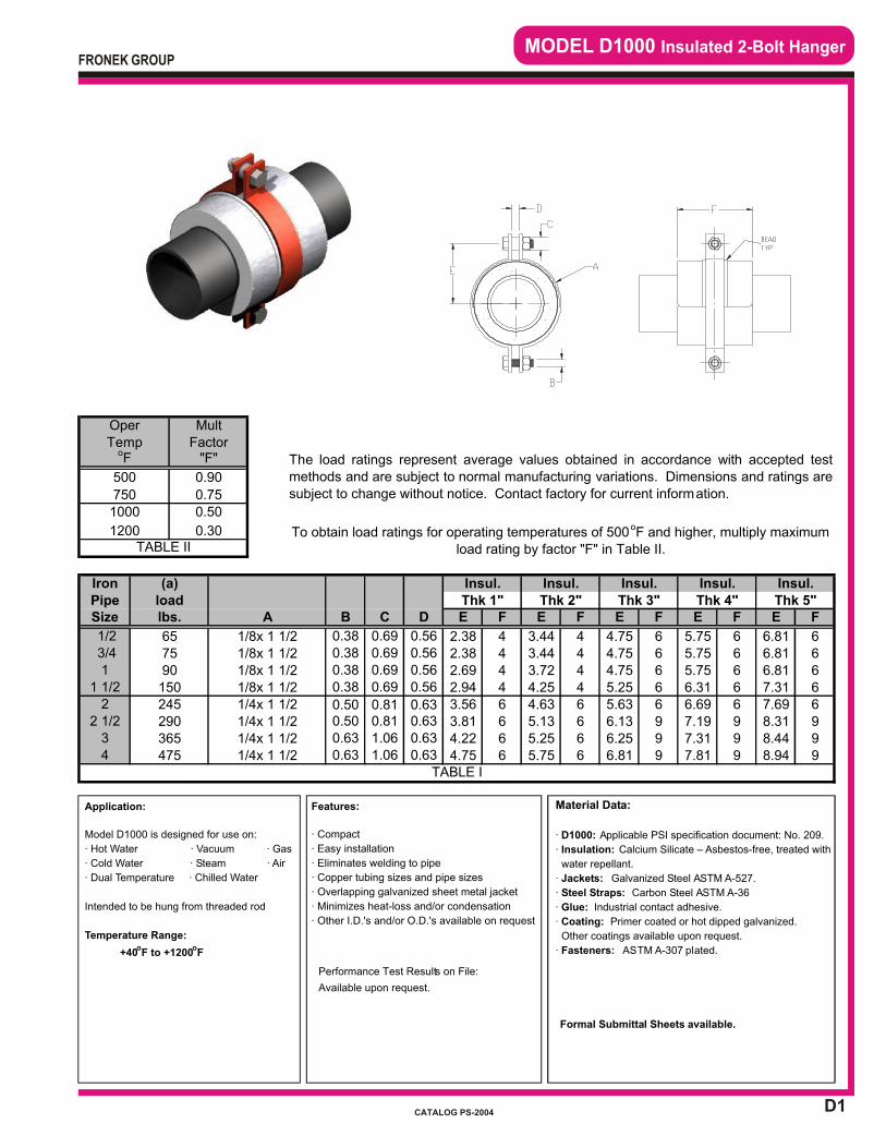
D1
MODEL D1000 Insulated 2-Bolt Hanger
Application:
Model D1000 is designed for use on:
· Hot Water · Vacuum · Gas
· Cold Water · Steam · Air
· Dual Temperature · Chilled Water
Intended to be hung from threaded rod
Temperature Range:
+40oF to +1200
oF
Features:
· Compact
· Easy installation
· Eliminates welding to pipe
· Copper tubing sizes and pipe sizes
· Overlapping galvanized sheet metal jacket
· Minimizes heat-loss and/or condensation
· Other I.D.'s and/or O.D.'s available on request
Performance Test Results on File:
Available upon request.
Material Data:
· D1000: Applicable PSI specification document: No. 209.
· Insulation: Calcium Silicate – Asbestos-free, treated with
water repellant.
· Jackets: Galvanized Steel ASTM A-527.
· Steel Straps: Carbon Steel ASTM A-36
· Glue: Industrial contact adhesive.
· Coating: Primer coated or hot dipped galvanized.
Other coatings available upon request.
· Fasteners: ASTM A-307 plated.
Formal Submittal Sheets available.
FRONEK GROUP
CATALOG PS-2004
IronPipeSize B C D E F E F E F E F E F
1/2 0.38 0.69 0.56 2.38 4 3.44 4 4.75 6 5.75 6 6.81 6 3/4 0.38 0.69 0.56 2.38 4 3.44 4 4.75 6 5.75 6 6.81 61 0.38 0.69 0.56 2.69 4 3.72 4 4.75 6 5.75 6 6.81 6
1 1/2 0.38 0.69 0.56 2.94 4 4.25 4 5.25 6 6.31 6 7.31 62 0.50 0.81 0.63 3.56 6 4.63 6 5.63 6 6.69 6 7.69 6
2 1/2 0.50 0.81 0.63 3.81 6 5.13 6 6.13 9 7.19 9 8.31 93 0.63 1.06 0.63 4.22 6 5.25 6 6.25 9 7.31 9 8.44 94 0.63 1.06 0.63 4.75 6 5.75 6 6.81 9 7.81 9 8.94 9
1/4x 1 1/21/4x 1 1/2
A
TABLE I
1/4x 1 1/21/4x 1 1/2
6575
1/8x 1 1/21/8x 1 1/2
90150
1/8x 1 1/21/8x 1 1/2
365475
245290
(a) Insul.
To obtain load ratings for operating temperatures of 500oF and higher, multiply maximum load rating by factor "F" in Table II.
1200 0.30
Insul. Insul. Insul.Insul.
lbs.load
Oper MultTemp
1000 0.50
oF "F"
TABLE II
500 0.90
750
Factor
0.75
The load ratings represent average values obtained in accordance with accepted testmethods and are subject to normal manufacturing variations. Dimensions and ratings aresubject to change without notice. Contact factory for current information.
Thk 4" Thk 5"Thk 2" Thk 3"Thk 1"
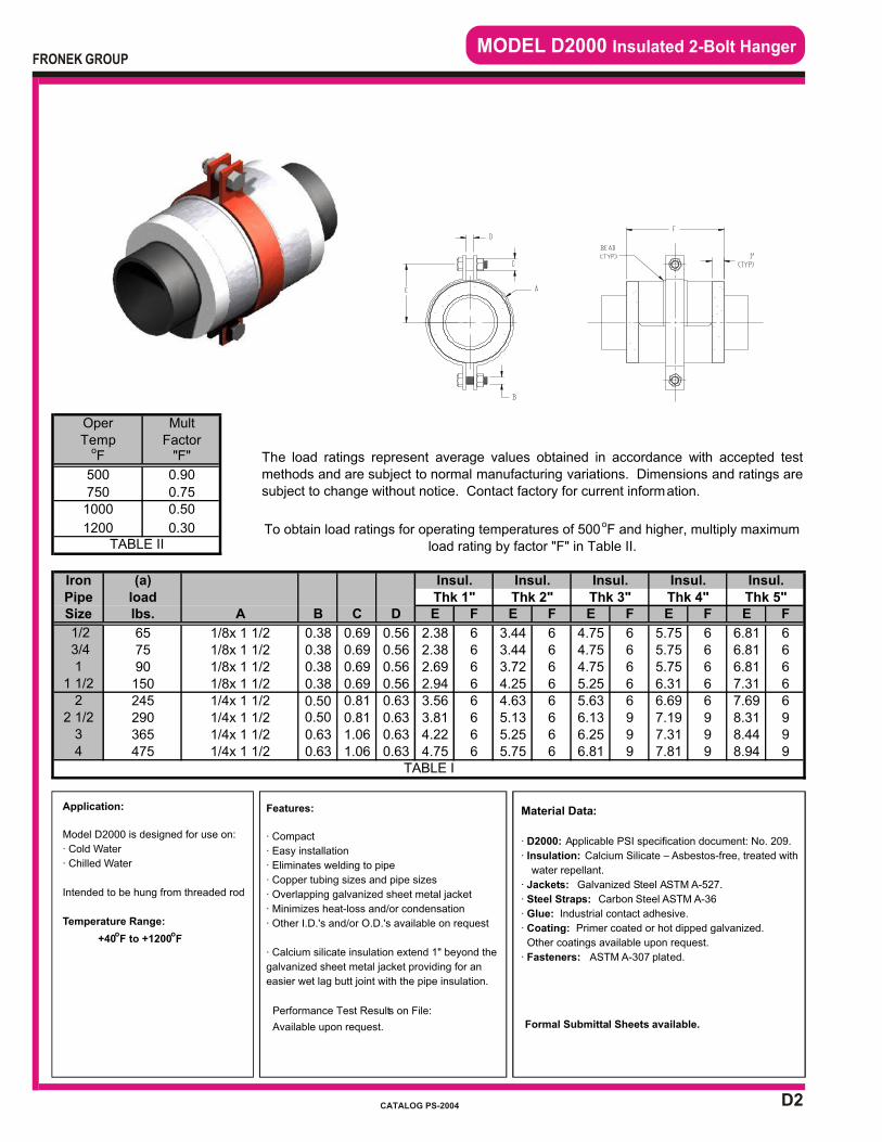
D2
MODEL D2000 Insulated 2-Bolt Hanger
Features:
· Compact
· Easy installation
· Eliminates welding to pipe
· Copper tubing sizes and pipe sizes
· Overlapping galvanized sheet metal jacket
· Minimizes heat-loss and/or condensation
· Other I.D.'s and/or O.D.'s available on request
· Calcium silicate insulation extend 1" beyond the
galvanized sheet metal jacket providing for an
easier wet lag butt joint with the pipe insulation.
Performance Test Results on File:
Available upon request.
Application:
Model D2000 is designed for use on:
· Cold Water
· Chilled Water
Intended to be hung from threaded rod
Temperature Range:
+40oF to +1200
oF
Material Data:
· D2000: Applicable PSI specification document: No. 209.
· Insulation: Calcium Silicate – Asbestos-free, treated with
water repellant.
· Jackets: Galvanized Steel ASTM A-527.
· Steel Straps: Carbon Steel ASTM A-36
· Glue: Industrial contact adhesive.
· Coating: Primer coated or hot dipped galvanized.
Other coatings available upon request.
· Fasteners: ASTM A-307 plated.
Formal Submittal Sheets available.
FRONEK GROUP
CATALOG PS-2004
IronPipeSize B C D E F E F E F E F E F
1/2 0.38 0.69 0.56 2.38 6 3.44 6 4.75 6 5.75 6 6.81 6 3/4 0.38 0.69 0.56 2.38 6 3.44 6 4.75 6 5.75 6 6.81 61 0.38 0.69 0.56 2.69 6 3.72 6 4.75 6 5.75 6 6.81 6
1 1/2 0.38 0.69 0.56 2.94 6 4.25 6 5.25 6 6.31 6 7.31 62 0.50 0.81 0.63 3.56 6 4.63 6 5.63 6 6.69 6 7.69 6
2 1/2 0.50 0.81 0.63 3.81 6 5.13 6 6.13 9 7.19 9 8.31 93 0.63 1.06 0.63 4.22 6 5.25 6 6.25 9 7.31 9 8.44 94 0.63 1.06 0.63 4.75 6 5.75 6 6.81 9 7.81 9 8.94 9
TABLE I
365475
1/4x 1 1/21/4x 1 1/2
245290
1/4x 1 1/21/4x 1 1/2
150
1000 0.50
90
TABLE II
A
1/8x 1 1/2
1/8x 1 1/21/8x 1 1/21/8x 1 1/2
75
500 0.90
65
1200 0.30
lbs.Thk 2"
750 0.75
Thk 3" Thk 4" Thk 5"
Temp Factor
load Thk 1"
The load ratings represent average values obtained in accordance with accepted testmethods and are subject to normal manufacturing variations. Dimensions and ratings aresubject to change without notice. Contact factory for current information.
To obtain load ratings for operating temperatures of 500oF and higher, multiply maximum load rating by factor "F" in Table II.
Insul. Insul. Insul. Insul.
Oper Mult
(a) Insul.
oF "F"
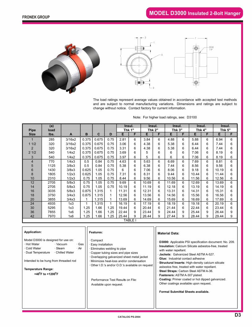
D3
MODEL D3000 Insulated 2-Bolt Hanger
Application:
Model D3000 is designed for use on:
· Hot Water · Vacuum · Gas
· Cold Water · Steam · Air
· Dual Temperature · Chilled Water
Intended to be hung from threaded rod
Temperature Range:
+40oF to +1200
oF
Material Data:
· D3000: Applicable PSI specification document: No. 209.
· Insulation: Calcium Silicate asbestos-free, treated
with water repellant.
· Jackets: Galvanized Steel ASTM A-527.
· Glue: Industrial contact adhesive
· Structural Inserts: High-density calcium silicate
asbestos free, treated with water repellant.
· Steel Straps: Carbon Steel ASTM A-36.
· Fasteners: ASTM A-307 plated.
· Coating: Primer coated or hot dipped galvanized.
Other coatings available upon request.
Formal Submittal Sheets available.
Features:
· Compact
· Easy installation
· Eliminates welding to pipe
· Copper tubing sizes and pipe sizes
· Overlapping galvanized sheet metal jacket
· Minimizes heat-loss and/or condensation
· Other I.D.'s and/or O.D.'s available on request
Performance Test Results on File:
Available upon request.
FRONEK GROUP
CATALOG PS-2004
B C D E F E F E F E F E F
0.375 0.675 0.75 2.81 6 3.84 6 4.88 6 5.88 6 6.94 6
0.375 0.675 0.75 3.06 6 4.38 6 5.38 6 6.44 6 7.44 6
0.375 0.675 0.75 3.31 6 4.38 6 5.38 6 6.44 6 7.44 60.375 0.675 0.75 3.69 6 5 6 6 6 7.06 6 8.19 6
0.375 0.675 0.75 3.97 6 5 6 6 6 7.06 6 8.19 6
0.5 0.84 0.75 4.63 6 5.63 6 6.69 6 7.69 6 8.81 60.5 0.84 0.75 5.38 6 6.38 6 7.44 6 8.56 6 9.56 6
0.625 1.05 0.75 6 6 7.06 6 8.06 6 9.18 6 10.19 60.625 1.05 0.75 7.31 6 8.31 6 9.44 6 10.44 6 11.44 60.75 1.05 0.75 8.44 6 9.56 6 10.56 6 11.56 6 12.56 60.75 1.05 0.75 9.69 6 10.69 6 11.69 6 12.69 6 13.69 60.75 1.05 0.75 10.19 6 11.19 6 12.18 6 13.19 6 14.19 60.875 1.315 1 11.31 6 12.31 6 13.31 6 14.31 6 15.31 60.875 1.315 1 12.56 6 13.56 6 14.56 6 15.56 6 16.56 6
1 1.315 1 13.69 6 14.69 6 15.69 6 16.69 6 17.69 61 1.315 1 16.19 6 17.19 6 18.19 6 19.18 6 20.19 6
1.25 1.66 1.25 19.44 6 20.44 6 21.44 6 22.44 6 23.44 61.25 1.66 1.25 22.44 9 23.44 9 24.44 9 25.44 9 26.44 91.25 1.66 1.25 25.44 9 26.44 9 27.44 9 28.44 9 29.44 9
(a) Insul.
Note: For higher load ratings, see: D3100
Insul. Insul. Insul. Insul.
The load ratings represent average values obtained in accordance with accepted test methodsand are subject to normal manufacturing variations. Dimensions and ratings are subject tochange without notice. Contact factory for current information.
Thk 3" Thk 4" Thk 5"Thk 1" Thk 2"Size lbs. APipe load
1 285 3/16x2
1 1/2 320 3/16x2
2 320 3/16x22 1/2 540 1/4x2
3 540 1/4x2
4 770 1/4x35 1125 3/8x36 1430 3/8x38 1805 1/2x310 2310 1/2x3
3855 3/4x3
12 2705 5/8x314 2705 5/8x3
7970 1x6
1x3
16 3035 5/8x318 3750 3/4x32024 4935
TABLE I
30 5295 1x336 7855 1x642
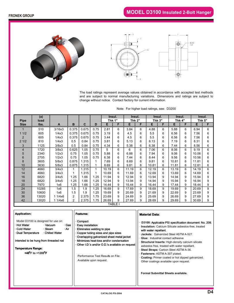
D4
MODEL D3100 Insulated 2-Bolt Hanger
Application:
Model D3100 is designed for use on:
· Hot Water · Vacuum · Gas
· Cold Water · Steam · Air
· Dual Temperature · Chilled Water
Intended to be hung from threaded rod
Temperature Range:
+40oF to +1200
oF
Application:
· Hot Water · Vacuum · Gas
· Cold Water · Steam · Air
· Dual Temperature · Chilled Water
Intended to be hung from threaded rod
Temperature Range:
+40o o
F
Features:
· Compact
· Easy installation
· Eliminates welding to pipe
· Copper tubing sizes and pipe sizes
· Overlapping galvanized sheet metal jacket
· Minimizes heat-loss and/or condensation
· Other I.D.'s and/or O.D.'s available on request
Features:
· Compact
· Easy installation
· Eliminates welding to pipe
· Copper tubing sizes and pipe sizes
· Overlapping galvanized sheet metal jacket
· Minimizes heat-loss and/or condensation
· Other I.D.'s and/or O.D.'s available on request
Performance Test Results on File:
Available upon request.
Material Data:
· Applicable PSI specification document: No. 209.
· Insulation: Calcium Silicate asbestos-free, treated
with water repellant.
· Jackets: Galvanized Steel ASTM A-527.
· Glue: Industrial contact adhesive
· Structural Inserts: High-density calcium silicate
asbestos free, treated with water repellant.
· Steel Straps: Carbon Steel ASTM A-36.
· Fasteners: ASTM A-307 plated.
· Coating: Primer coated or hot dipped galvanized.
Other coatings available upon request.
Material Data:
· D3100: Applicable PSI specification document: No. 209.
with water repellant.
Formal Submittal Sheets available.
FRONEK GROUP
CATALOG PS-2004
B C D E F E F E F E F E F
0.375 0.675 0.75 2.81 6 3.84 6 4.88 6 5.88 6 6.94 6
0.375 0.675 0.75 3.19 6 4.5 6 5.5 6 6.56 6 7.56 6
0.375 0.675 0.75 3.44 6 4.5 6 5.5 6 6.56 6 7.56 60.5 0.84 0.75 3.81 6 5.13 6 6.13 6 7.19 6 8.31 6
0.5 0.84 0.75 4.34 6 5.38 6 6.38 6 7.44 6 8.56 6
0.625 1.05 0.75 5 6 6 6 7.06 6 8.06 6 9.19 60.75 1.05 0.75 5.88 6 6.88 6 7.94 6 9.06 6 10.06 60.75 1.05 0.75 6.38 6 7.44 6 8.44 6 9.56 6 10.56 60.875 1.315 1 7.69 6 8.69 6 9.81 6 10.81 6 11.81 60.875 1.315 1 8.69 6 9.81 6 10.81 6 11.81 6 12.81 6
1 1.315 1 10.19 6 11.19 6 12.19 6 13.19 6 14.19 61 1.315 1 10.69 6 11.69 6 12.69 6 13.69 6 14.69 6
1.25 1.66 1.25 11.94 9 12.94 9 13.94 9 14.94 9 15.94 91.25 1.66 1.25 12.94 9 13.94 9 14.94 9 15.94 9 16.94 91.25 1.66 1.25 14.44 9 15.44 9 16.44 9 17.44 9 18.44 91.5 1.9 1.25 16.69 9 17.69 9 18.69 9 19.69 9 20.69 91.5 1.9 1.25 19.69 9 20.69 9 21.69 9 22.69 9 23.69 92 2.375 1.75 23.69 9 24.69 9 25.69 9 26.69 9 27.69 92 2.375 1.75 26.69 9 27.69 9 28.69 9 29.69 9 30.69 9
The load ratings represent average values obtained in accordance with accepted test methodsand are subject to normal manufacturing variations. Dimensions and ratings are subject tochange without notice. Contact factory for current information.
Note: For higher load ratings, see: D3200
Insul. Insul. Insul. Insul.Insul.(a)Pipe load Thk 1" Thk 2" Thk 3" Thk 4" Thk 5"Size lbs. A
1 510 3/16x3
1 1/2 605 1/4x3
2 605 1/4x32 1/2 810 1/4x3
3 1125 3/8x3
4 1720 3/8x35 2340 1/2x36 2705 1/2x38 3605 5/8x310 3630 5/8x312 4660 3/4x314 4660 3/4x316 6820 3/4x518 6820 3/4x520 7970 1x6
10285 1x630 10600 1x624
TABLE I
36 13020 1 1/4x642 13020 1 1/4x6
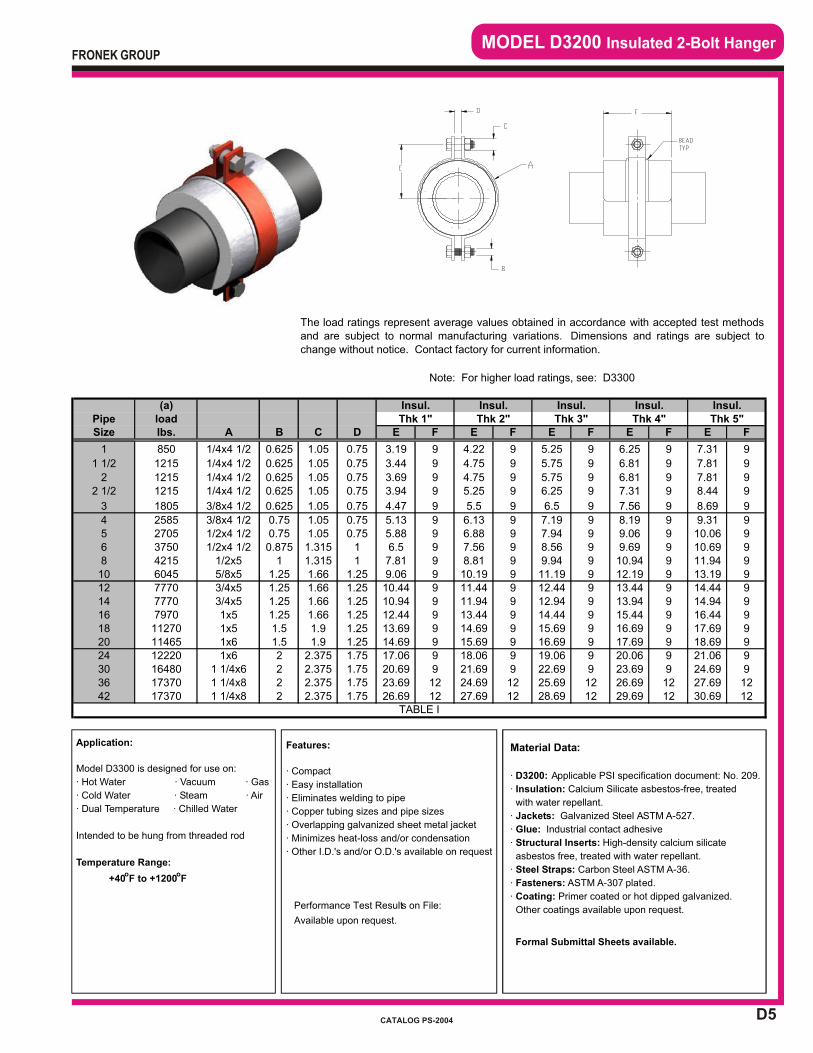
D5
MODEL D3200 Insulated 2-Bolt Hanger
Application:
Model D3300 is designed for use on:
· Hot Water · Vacuum · Gas
· Cold Water · Steam · Air
· Dual Temperature · Chilled Water
Intended to be hung from threaded rod
Temperature Range:
+40oF to +1200
oF
Features:
· Compact
· Easy installation
· Eliminates welding to pipe
· Copper tubing sizes and pipe sizes
· Overlapping galvanized sheet metal jacket
· Minimizes heat-loss and/or condensation
· Other I.D.'s and/or O.D.'s available on request
Performance Test Results on File:
Available upon request.
Material Data:
· D3200: Applicable PSI specification document: No. 209.
· Insulation: Calcium Silicate asbestos-free, treated
with water repellant.
· Jackets: Galvanized Steel ASTM A-527.
· Glue: Industrial contact adhesive
· Structural Inserts: High-density calcium silicate
asbestos free, treated with water repellant.
· Steel Straps: Carbon Steel ASTM A-36.
· Fasteners: ASTM A-307 plated.
· Coating: Primer coated or hot dipped galvanized.
Other coatings available upon request.
Formal Submittal Sheets available.
FRONEK GROUP
CATALOG PS-2004
B C D E F E F E F E F E F
0.625 1.05 0.75 3.19 9 4.22 9 5.25 9 6.25 9 7.31 9
0.625 1.05 0.75 3.44 9 4.75 9 5.75 9 6.81 9 7.81 9
0.625 1.05 0.75 3.69 9 4.75 9 5.75 9 6.81 9 7.81 90.625 1.05 0.75 3.94 9 5.25 9 6.25 9 7.31 9 8.44 9
0.625 1.05 0.75 4.47 9 5.5 9 6.5 9 7.56 9 8.69 9
0.75 1.05 0.75 5.13 9 6.13 9 7.19 9 8.19 9 9.31 90.75 1.05 0.75 5.88 9 6.88 9 7.94 9 9.06 9 10.06 90.875 1.315 1 6.5 9 7.56 9 8.56 9 9.69 9 10.69 9
1 1.315 1 7.81 9 8.81 9 9.94 9 10.94 9 11.94 91.25 1.66 1.25 9.06 9 10.19 9 11.19 9 12.19 9 13.19 91.25 1.66 1.25 10.44 9 11.44 9 12.44 9 13.44 9 14.44 91.25 1.66 1.25 10.94 9 11.94 9 12.94 9 13.94 9 14.94 91.25 1.66 1.25 12.44 9 13.44 9 14.44 9 15.44 9 16.44 91.5 1.9 1.25 13.69 9 14.69 9 15.69 9 16.69 9 17.69 91.5 1.9 1.25 14.69 9 15.69 9 16.69 9 17.69 9 18.69 92 2.375 1.75 17.06 9 18.06 9 19.06 9 20.06 9 21.06 92 2.375 1.75 20.69 9 21.69 9 22.69 9 23.69 9 24.69 92 2.375 1.75 23.69 12 24.69 12 25.69 12 26.69 12 27.69 122 2.375 1.75 26.69 12 27.69 12 28.69 12 29.69 12 30.69 12
The load ratings represent average values obtained in accordance with accepted test methodsand are subject to normal manufacturing variations. Dimensions and ratings are subject tochange without notice. Contact factory for current information.
Note: For higher load ratings, see: D3300
(a) Insul. Insul. Insul. Insul. Insul.Pipe load Thk 1" Thk 2" Thk 3" Thk 4" Thk 5"Size lbs. A
1 850 1/4x4 1/2
1 1/2 1215 1/4x4 1/2
2 1215 1/4x4 1/22 1/2 1215 1/4x4 1/2
3 1805 3/8x4 1/2
4 2585 3/8x4 1/25 2705 1/2x4 1/26 3750 1/2x4 1/28 4215 1/2x510 6045 5/8x512 7770 3/4x514 7770 3/4x516 7970 1x518 11270 1x520 11465 1x624 12220 1x630 16480 1 1/4x6
TABLE I
36 17370 1 1/4x842 17370 1 1/4x8
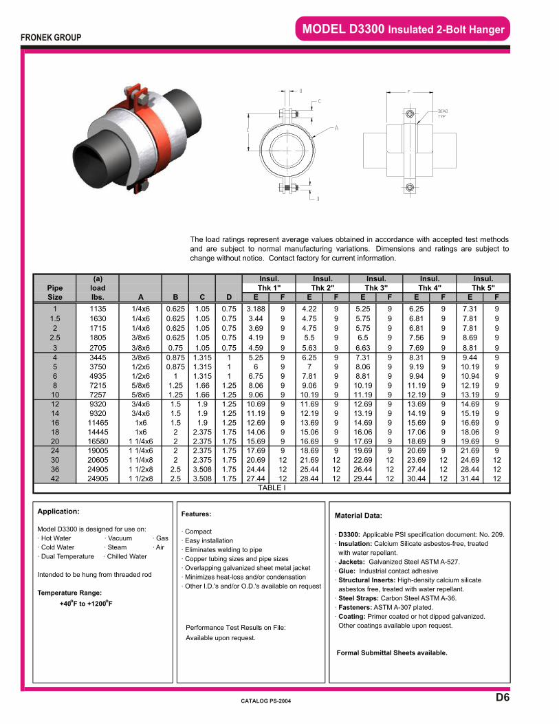
D6
MODEL D3300 Insulated 2-Bolt Hanger
Application:
Model D3300 is designed for use on:
· Hot Water · Vacuum · Gas
· Cold Water · Steam · Air
· Dual Temperature · Chilled Water
Intended to be hung from threaded rod
Temperature Range:
+40oF to +1200
oF
Material Data:
· D3300: Applicable PSI specification document: No. 209.
· Insulation: Calcium Silicate asbestos-free, treated
with water repellant.
· Jackets: Galvanized Steel ASTM A-527.
· Glue: Industrial contact adhesive
· Structural Inserts: High-density calcium silicate
asbestos free, treated with water repellant.
· Steel Straps: Carbon Steel ASTM A-36.
· Fasteners: ASTM A-307 plated.
· Coating: Primer coated or hot dipped galvanized.
Other coatings available upon request.
Formal Submittal Sheets available.
Features:
· Compact
· Easy installation
· Eliminates welding to pipe
· Copper tubing sizes and pipe sizes
· Overlapping galvanized sheet metal jacket
· Minimizes heat-loss and/or condensation
· Other I.D.'s and/or O.D.'s available on request
Performance Test Results on File:
Available upon request.
FRONEK GROUP
CATALOG PS-2004
B C D E F E F E F E F E F
0.625 1.05 0.75 3.188 9 4.22 9 5.25 9 6.25 9 7.31 9
0.625 1.05 0.75 3.44 9 4.75 9 5.75 9 6.81 9 7.81 9
0.625 1.05 0.75 3.69 9 4.75 9 5.75 9 6.81 9 7.81 90.625 1.05 0.75 4.19 9 5.5 9 6.5 9 7.56 9 8.69 9
0.75 1.05 0.75 4.59 9 5.63 9 6.63 9 7.69 9 8.81 9
0.875 1.315 1 5.25 9 6.25 9 7.31 9 8.31 9 9.44 90.875 1.315 1 6 9 7 9 8.06 9 9.19 9 10.19 9
1 1.315 1 6.75 9 7.81 9 8.81 9 9.94 9 10.94 91.25 1.66 1.25 8.06 9 9.06 9 10.19 9 11.19 9 12.19 91.25 1.66 1.25 9.06 9 10.19 9 11.19 9 12.19 9 13.19 91.5 1.9 1.25 10.69 9 11.69 9 12.69 9 13.69 9 14.69 91.5 1.9 1.25 11.19 9 12.19 9 13.19 9 14.19 9 15.19 91.5 1.9 1.25 12.69 9 13.69 9 14.69 9 15.69 9 16.69 92 2.375 1.75 14.06 9 15.06 9 16.06 9 17.06 9 18.06 92 2.375 1.75 15.69 9 16.69 9 17.69 9 18.69 9 19.69 92 2.375 1.75 17.69 9 18.69 9 19.69 9 20.69 9 21.69 92 2.375 1.75 20.69 12 21.69 12 22.69 12 23.69 12 24.69 12
2.5 3.508 1.75 24.44 12 25.44 12 26.44 12 27.44 12 28.44 122.5 3.508 1.75 27.44 12 28.44 12 29.44 12 30.44 12 31.44 12
Insul. Insul. Insul.(a) Insul.
The load ratings represent average values obtained in accordance with accepted test methodsand are subject to normal manufacturing variations. Dimensions and ratings are subject tochange without notice. Contact factory for current information.
Pipe load Thk 1" Thk 2" Thk 3" Thk 4" Thk 5"Insul.
Size lbs. A
1 1135 1/4x6
1.5 1630 1/4x6
2 1715 1/4x62.5 1805 3/8x6
3 2705 3/8x6
4 3445 3/8x65 3750 1/2x66 4935 1/2x68 7215 5/8x610 7257 5/8x612 9320 3/4x614 9320 3/4x616 11465 1x618 14445 1x620 16580 1 1/4x624 19005 1 1/4x630 20605 1 1/4x8
TABLE I
36 24905 1 1/2x842 24905 1 1/2x8

D7
MODEL D4000 Insulated 2-Rod Hanger
Application:
Model D4000 is designed for use on:
· Hot Water · Vacuum · Gas
· Cold Water · Steam · Air
· Dual Temperature · Chilled Water
Intended to be hung from two threaded rods
in close overhead clearance conditions.
Temperature Range:
+40oF to +1200
oF
Features:
· Compact
· Easy installation
· Eliminates welding to pipe
· Copper tubing sizes and pipe sizes
· Overlapping galvanized sheet metal jacket
· Minimizes heat-loss and/or condensation
· Other I.D.'s and/or O.D.'s available on request
Performance Test Results on File:
Available upon request.
Material Data:
· D4000: Applicable PSI specification document: No. 209.
· Insulation: Calcium Silicate asbestos-free, treated
with water repellant.
· Jackets: Galvanized Steel ASTM A-527.
· Glue: Industrial contact adhesive
· Structural Inserts: High-density calcium silicate
asbestos free, treated with water repellant.
· Steel Straps: Carbon Steel ASTM A-36.
· Fasteners: ASTM A-307 plated.
· Coating: Primer coated or hot dipped galvanized.
Other coatings available upon request.
Formal Submittal Sheets available.
FRONEK GROUP
CATALOG PS-2004
PipeSize B C D E C D E C D E C D E
1/2 0.375 1.63 4.75 6 2.69 6.875 6 4.0 9.5 6 5.0 11.5 6 3/4 0.375 1.63 4.75 6 2.69 6.875 6 4.0 9.5 6 5.0 11.5 61 0.375 1.94 5.375 6 2.97 7.437 6 4.0 9.5 6 5.0 11.5 6
1 1/2 0.375 2.19 5.875 6 3.50 8.5 6 4.5 10.5 6 5.56 12.625 62 0.375 2.44 6.875 6 3.50 9 6 4.5 11 6 5.56 13.125 6
2 1/2 0.375 2.69 7.375 6 4.0 10 6 5.0 12 9 6.06 14.125 93 0.375 2.97 7.937 6 4.0 10 6 5.0 12 9 6.06 14.125 94 0.375 3.5 9 6 4.5 11 6 5.56 13.125 9 6.56 15.125 9
Oper MultTemp Factor
oF "F"
500 0.90750 0.75
1000 0.50
The load ratings represent average values obtained in accordance with accepted test methods and aresubject to normal manufacturing variations. Dimensions and ratings are subject to change without notice.Contact factory for current information.
(a) Insul. Insul. Insul. Insul.
1200 0.30TABLE II
(a)
Thk 4"lbs. A
65 1/8x1 1/2
load Thk 1" Thk 2" Thk 3"
75 1/8x1 1/290 1/8x1 1/2130 1/8x1 1/2245 1/4x1 1/2
475 1/4x1 1/2TABLE I
290 1/4x1 1/2365 1/4x1 1/2
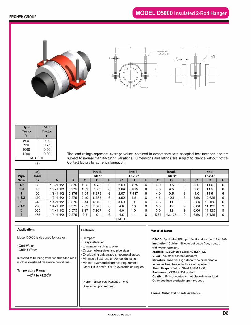
D8
MODEL D5000 Insulated 2-Rod Hanger
Application:
Model D5000 is designed for use on:
· Cold Water
· Chilled Water
Intended to be hung from two threaded rods
in close overhead clearance conditions.
Temperature Range:
+40oF to +1200
oF
Material Data:
· D5000: Applicable PSI specification document: No. 209.
· Insulation: Calcium Silicate asbestos-free, treated
with water repellant.
· Jackets: Galvanized Steel ASTM A-527.
· Glue: Industrial contact adhesive
· Structural Inserts: High-density calcium silicate
asbestos free, treated with water repellant.
· Steel Straps: Carbon Steel ASTM A-36.
· Fasteners: ASTM A-307 plated.
· Coating: Primer coated or hot dipped galvanized.
Other coatings available upon request.
Formal Submittal Sheets available.
Features:
· Compact
· Easy installation
· Eliminates welding to pipe
· Copper tubing sizes and pipe sizes
· Overlapping galvanized sheet metal jacket
· Minimizes heat-loss and/or condensation
· Minimal overhead clearance requirement
· Other I.D.'s and/or O.D.'s available on request
Performance Test Results on File:
Available upon request.
FRONEK GROUP
CATALOG PS-2004
PipeSize B C D E C D E C D E C D E
1/2 0.375 1.63 4.75 6 2.69 6.875 6 4.0 9.5 6 5.0 11.5 6 3/4 0.375 1.63 4.75 6 2.69 6.875 6 4.0 9.5 6 5.0 11.5 61 0.375 1.94 5.375 6 2.97 7.437 6 4.0 9.5 6 5.0 11.5 6
1 1/2 0.375 2.19 5.875 6 3.50 8.5 6 4.5 10.5 6 5.56 12.625 62 0.375 2.44 6.875 6 3.50 9 6 4.5 11 6 5.56 13.125 6
2 1/2 0.375 2.69 7.375 6 4.0 10 6 5.0 12 9 6.06 14.125 93 0.375 2.97 7.937 6 4.0 10 6 5.0 12 9 6.06 14.125 94 0.375 3.5 9 6 4.5 11 6 5.56 13.125 9 6.56 15.125 9
Oper MultTemp Factor
oF "F"
500 0.90750 0.75
1000 0.50
The load ratings represent average values obtained in accordance with accepted test methods and aresubject to normal manufacturing variations. Dimensions and ratings are subject to change without notice.Contact factory for current information.
(a) Insul. Insul. Insul. Insul.
1200 0.30TABLE II
(a)
Thk 4"lbs. A
65 1/8x1 1/2
load Thk 1" Thk 2" Thk 3"
75 1/8x1 1/290 1/8x1 1/2130 1/8x1 1/2245 1/4x1 1/2
475 1/4x1 1/2TABLE I
290 1/4x1 1/2365 1/4x1 1/2
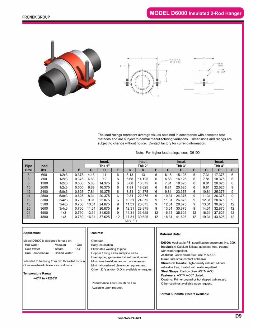
D9
MODEL D6000 Insulated 2-Rod Hanger
Application:
Model D6000 is designed for use on:
· Hot Water · Vacuum · Gas
· Cold Water · Steam · Air
· Dual Temperature · Chilled Water
Intended to be hung from two threaded rods in
close overhead clearance conditions.
Temperature Range:
+40oF to +1200
oF
Material Data:
· D6000: Applicable PSI specification document: No. 209.
· Insulation: Calcium Silicate asbestos-free, treated
with water repellant.
· Jackets: Galvanized Steel ASTM A-527.
· Glue: Industrial contact adhesive
· Structural Inserts: High-density calcium silicate
asbestos free, treated with water repellant.
· Steel Straps: Carbon Steel ASTM A-36.
· Fasteners: ASTM A-307 plated.
· Coating: Primer coated or hot dipped galvanized.
Other coatings available upon request.
Formal Submittal Sheets available.
Features:
· Compact
· Easy installation
· Eliminates welding to pipe
· Copper tubing sizes and pipe sizes
· Overlapping galvanized sheet metal jacket
· Minimizes heat-loss and/or condensation
· Minimal overhead clearance requirement
· Other I.D.'s and/or O.D.'s available on request
Performance Test Results on File:
Available upon request.
FRONEK GROUP
CATALOG PS-2004
PipeSize B C D E C D E C D E C D E
5 0.375 4.13 11 6 5.13 13 6 6.18 15.125 6 7.31 17.375 66 0.375 4.63 12 6 5.68 14.125 6 6.68 16.125 6 7.81 18.375 68 0.500 5.68 14.375 6 6.68 16.375 6 7.81 18.625 6 8.81 20.625 610 0.500 6.69 16.375 6 7.81 18.625 6 8.81 20.625 6 9.81 22.625 912 0.625 7.81 19.375 6 8.81 21.375 6 9.81 23.375 6 10.81 25.375 914 0.625 8.31 20.375 6 9.31 22.375 6 10.31 24.375 9 11.31 26.375 916 0.750 9.31 22.875 6 10.31 24.875 9 11.31 26.875 9 12.31 28.875 918 0.750 10.31 24.875 9 11.31 26.875 9 12.31 28.875 9 13.31 30.875 1220 0.750 11.31 26.875 9 12.31 28.875 9 13.31 30.875 9 14.31 32.875 1224 0.750 13.31 31.625 9 14.31 33.625 12 15.31 35.625 12 16.31 37.625 1230 0.750 16.31 37.625 12 17.31 39.625 12 18.31 41.625 12 19.31 43.625 12
The load ratings represent average values obtained in accordance with accepted test methods and are subject to normal manufacturing variations. Dimensions and ratings are subject to change without notice. Contact factory for current information.
Note: For higher load ratings, see: D6100
Insul. Insul. Insul. Insul.Thk 4"
lbs. A
600 1/2x3
load Thk 1" Thk 2" Thk 3"
800 1/2x31300 1/2x32000 1/2x32400 5/8x32500 5/8x33300 3/4x33500 3/4x33600 3/4x3
TABLE I
4500 1x34800 1x3
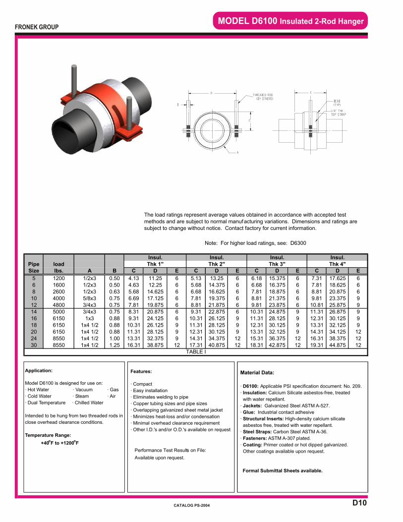
D10
MODEL D6100 Insulated 2-Rod Hanger
Application:
Model D6100 is designed for use on:
· Hot Water · Vacuum · Gas
· Cold Water · Steam · Air
· Dual Temperature · Chilled Water
Intended to be hung from two threaded rods in
close overhead clearance conditions.
Temperature Range:
+40oF to +1200
oF
Material Data:
· D6100: Applicable PSI specification document: No. 209.
· Insulation: Calcium Silicate asbestos-free, treated
with water repellant.
· Jackets: Galvanized Steel ASTM A-527.
· Glue: Industrial contact adhesive
· Structural Inserts: High-density calcium silicate
asbestos free, treated with water repellant.
· Steel Straps: Carbon Steel ASTM A-36.
· Fasteners: ASTM A-307 plated.
· Coating: Primer coated or hot dipped galvanized.
Other coatings available upon request.
Formal Submittal Sheets available.
Features:
· Compact
· Easy installation
· Eliminates welding to pipe
· Copper tubing sizes and pipe sizes
· Overlapping galvanized sheet metal jacket
· Minimizes heat-loss and/or condensation
· Minimal overhead clearance requirement
· Other I.D.'s and/or O.D.'s available on request
Performance Test Results on File:
Available upon request.
FRONEK GROUP
CATALOG PS-2004
PipeSize B C D E C D E C D E C D E
5 0.50 4.13 11.25 6 5.13 13.25 6 6.18 15.375 6 7.31 17.625 66 0.50 4.63 12.25 6 5.68 14.375 6 6.68 16.375 6 7.81 18.625 68 0.63 5.68 14.625 6 6.68 16.625 6 7.81 18.875 6 8.81 20.875 610 0.75 6.69 17.125 6 7.81 19.375 6 8.81 21.375 6 9.81 23.375 912 0.75 7.81 19.875 6 8.81 21.875 6 9.81 23.875 6 10.81 25.875 914 0.75 8.31 20.875 6 9.31 22.875 6 10.31 24.875 9 11.31 26.875 916 0.88 9.31 24.125 6 10.31 26.125 9 11.31 28.125 9 12.31 30.125 918 0.88 10.31 26.125 9 11.31 28.125 9 12.31 30.125 9 13.31 32.125 920 0.88 11.31 28.125 9 12.31 30.125 9 13.31 32.125 9 14.31 34.125 1224 1.00 13.31 32.375 9 14.31 34.375 12 15.31 36.375 12 16.31 38.375 1230 1.25 16.31 38.875 12 17.31 40.875 12 18.31 42.875 12 19.31 44.875 12
The load ratings represent average values obtained in accordance with accepted test methods and are subject to normal manufacturing variations. Dimensions and ratings are subject to change without notice. Contact factory for current information.
Note: For higher load ratings, see: D6300
Insul. Insul. Insul. Insul.Thk 4"
lbs. A
1200 1/2x3
load Thk 1" Thk 2" Thk 3"
1600 1/2x32600 1/2x34000 5/8x34800 3/4x35000 3/4x36150 1x36150 1x4 1/26150 1x4 1/2
TABLE I
8550 1x4 1/28550 1x4 1/2
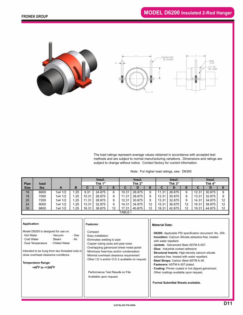
D11
MODEL D6200 Insulated 2-Rod Hanger
Application:
Model D6200 is designed for use on:
· Hot Water · Vacuum · Gas
· Cold Water · Steam · Air
· Dual Temperature · Chilled Water
Intended to be hung from two threaded rods in
close overhead clearance conditions.
Temperature Range:
+40oF to +1200
oF
Material Data:
· D6200: Applicable PSI specification document: No. 209.
· Insulation: Calcium Silicate asbestos-free, treated
with water repellant.
· Jackets: Galvanized Steel ASTM A-527.
· Glue: Industrial contact adhesive
· Structural Inserts: High-density calcium silicate
asbestos free, treated with water repellant.
· Steel Straps: Carbon Steel ASTM A-36.
· Fasteners: ASTM A-307 plated.
· Coating: Primer coated or hot dipped galvanized.
Other coatings available upon request.
Formal Submittal Sheets available.
Features:
· Compact
· Easy installation
· Eliminates welding to pipe
· Copper tubing sizes and pipe sizes
· Overlapping galvanized sheet metal jacket
· Minimizes heat-loss and/or condensation
· Minimal overhead clearance requirement
· Other I.D.'s and/or O.D.'s available on request
Performance Test Results on File:
Available upon request.
FRONEK GROUP
CATALOG PS-2004
PipeSize B C D E C D E C D E C D E
16 1.25 9.31 24.875 6 10.31 26.875 9 11.31 28.875 9 12.31 30.875 918 1.25 10.31 26.875 9 11.31 28.875 9 12.31 30.875 9 13.31 32.875 920 1.25 11.31 28.875 9 12.31 30.875 9 13.31 32.875 9 14.31 34.875 1224 1.25 13.31 32.875 9 14.31 34.875 12 15.31 36.875 12 16.31 38.875 1230 1.25 16.31 38.875 12 17.31 40.875 12 18.31 42.875 12 19.31 44.875 12
The load ratings represent average values obtained in accordance with accepted test methods and are subject to normal manufacturing variations. Dimensions and ratings are subject to change without notice. Contact factory for current information.
Note: For higher load ratings, see: D6300
Insul.load Thk 1" Thk 2" Thk 3" Thk 4"
Insul. Insul. Insul.
lbs. A
6600 1x4 1/27000 1x4 1/27200 1x4 1/2
TABLE I
9000 1x4 1/29600 1x4 1/2

D12
MODEL D6300 Insulated 2-Rod Hanger
Application:
Model D6300 is designed for use on:
· Hot Water · Vacuum · Gas
· Cold Water · Steam · Air
· Dual Temperature · Chilled Water
Intended to be hung from two threaded rods in
close overhead clearance conditions.
Temperature Range:
+40oF to +1200
oF
Material Data:
· D6300: Applicable PSI specification document: No. 209.
· Insulation: Calcium Silicate asbestos-free, treated
with water repellant.
· Jackets: Galvanized Steel ASTM A-527.
· Glue: Industrial contact adhesive
· Structural Inserts: High-density calcium silicate
asbestos free, treated with water repellant.
· Steel Straps: Carbon Steel ASTM A-36.
· Fasteners: ASTM A-307 plated.
· Coating: Primer coated or hot dipped galvanized.
Other coatings available upon request.
Formal Submittal Sheets available.
Features:
· Compact
· Easy installation
· Eliminates welding to pipe
· Copper tubing sizes and pipe sizes
· Overlapping galvanized sheet metal jacket
· Minimizes heat-loss and/or condensation
· Minimal overhead clearance requirement
· Other I.D.'s and/or O.D.'s available on request
Performance Test Results on File:
Available upon request.
FRONEK GROUP
CATALOG PS-2004
BoltPipe load TorqSize lbs. ft-lbs A B C D E C D E C D E C D E
20 8200 50 1x6 1.25 11.31 28.875 9 12.31 30.875 9 13.31 32.875 9 14.31 34.875 1224 11400 50 1x6 1.50 13.31 33.375 9 14.31 35.375 12 15.31 37.375 12 16.31 39.375 1230 11400 50 1x6 1.50 16.31 39.375 12 17.31 41.375 12 18.31 43.375 12 19.31 45.375 12
The load ratings represent average values obtained in accordance with accepted test methods and are subject to normal manufacturing variations. Dimensions and ratings are subject to change without notice. Contact factory for current information.
Insul. Insul. Insul. Insul.
TABLE I
Thk 3" Thk 4"Thk 1" Thk 2"

INTRODUCTION SECTION “E”
INTRODUCTION
SECTION “E”
INSULATED PIPE RISER CLAMPS
APPLICATION – Commercial, Light and Heavy Industrial and Large HVAC Distribution Systems
Models E1000 – E1300 Insulated Pipe Riser Clamps for restraint of downward loads only.
These models require the field welding of two (2) factory supplied thrust plates against the upper side of the riser clamp. The higher the model number in this series, the higher the load rating.
Models E2000 – E2300 Insulated Pipe Riser Clamps for restraint of either, or both, upward or
downward loads. These models require field welding of two (2) factory supplied thrust plates on both the upper and lower sides of the riser clamp. The higher the model number in this series, the higher the load rating.
Pipe Shields Inc. can also supply similar clamps (not catalogued) for the support of pipe insulation. Insulated clamps (not catalogued) can be supplied for use as pipe guides on vertical risers.
If your requirements are not covered by the Product Data Sheets in this catalog, please contact us at 713-731-0030 or 1-800-787-5914.
Please acquaint yourself with the selection guide at the front of this catalog and the section index on the page following this introduction, for assistance in determining the most
appropriate support for your application.
FRONEK GROUP
CATALOG PS-2004
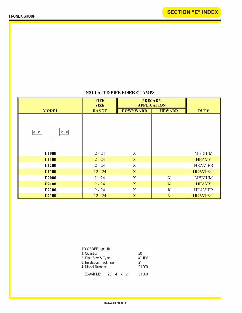
PIPESIZE
MODEL RANGE DOWNWARD UPWARD DUTY
E1000 2 - 24 X MEDIUM
E1100 2 - 24 X HEAVY
E1200 2 - 24 X HEAVIER
E1300 12 - 24 X HEAVIEST
E2000 2 - 24 X X MEDIUM
E2100 2 - 24 X X HEAVY
E2200 2 - 24 X X HEAVIER
E2300 12 - 24 X X HEAVIEST
INSULATED PIPE RISER CLAMPS
PRIMARYAPPLICATION
SECTION “E” INDEX
TO ORDER, specify:1. Quantity 202. Pipe Size & Type 4” IPS3. Insulation Thickness 2”4. Model Number E1000
EXAMPLE: (20) 4 x 2 E1000
FRONEK GROUP
CATALOG PS-2004

E1
Insulated Pipe Riser Clampsfor Downward Loads
MODEL E1000, MODEL E1010,MODEL E1020, MODEL E1030
Application:
Model E1000 through E1030 is designed for
use on:
· Hot Water · Vacuum · Gas
· Cold Water · Steam · Air
· Dual Temperature · Chilled Water
Intended for installation on:
· Vertical runs of insulated pipe with
downward load only.
Other:
·For handling both upward and downward
loads, see E2000
Temperature Range:
+40oF to +650oF
Features:
· All pipe sizes
· Easy Installation
· Positive stop - axially downward
· May be supported from below or above
· Overlapping galvanized sheet metal jacket
· Insulating structural inserts for load transfer
· Other I.D.'s and/or O.D.'s Available on Request
· Eliminates condensation sweating on chilled
water risers
Performance Test Results on File:
Available upon request
Material Data:· E1000 - E1030: specification document: No. 206.
· Steel Top Thrust Plates:
Model ASTM For Pipe Material
E1000 A36 Carbon-Steel
E1010 A387GR.11 Chrome-Moly
E1020 A515GR.70 Carbon Silicon
E1030 A304L Stainless Steel
· Insulation: Calcium Silicate asbestos-free, treated
with water repellant.
· Jackets: Galvanized Steel ASTM A-527.
· Glue: Industrial contact adhesive
· Structural Inserts: High-density calcium silicate
asbestos free, treated with water repellant.
· Steel Straps/Base:Carbon Steel ASTM A-36.
· Fasteners: ASTM A-307 plated.
· Coating: Primer coated or hot dipped galvanized.
Other coatings available upon request.
Formal Submittal Sheets available.
FRONEK GROUP
CATALOG PS-2004
Pipe LoadSize lbs A F G H F G H F G H F G H
2 250 0.63 0.25 1.50 0.625 3.69 5.69 5.13 4.75 6.75 7.25 5.75 7.75 9.25 6.81 8.81 11.382 1/2 300 0.63 0.25 1.50 0.625 3.94 5.94 5.63 5.25 7.25 8.25 6.25 8.25 10.25 7.31 9.31 12.38
3 400 0.63 0.25 1.50 0.625 4.22 6.22 6.19 5.25 7.25 8.25 6.25 8.25 10.25 7.31 9.31 12.384 600 0.63 0.25 1.50 0.625 4.75 6.75 7.25 5.75 7.75 9.25 6.81 8.81 11.38 7.81 9.81 13.385 800 0.63 0.25 1.50 0.625 5.25 7.25 8.25 6.25 8.25 10.25 7.31 9.31 12.38 8.44 10.44 14.636 1000 0.63 0.25 2.00 0.625 5.75 7.75 9.25 6.81 8.81 11.38 7.81 9.81 13.38 8.94 10.94 15.638 1300 0.63 0.25 2.00 0.625 6.81 8.81 11.38 7.81 9.81 13.38 8.94 10.94 15.63 9.94 11.94 17.6310 1600 0.63 0.38 3.00 0.625 8.06 10.31 13.63 9.19 11.44 15.88 10.19 12.44 17.88 11.19 13.44 19.8812 1700 0.63 0.38 3.00 0.625 9.19 11.44 15.88 10.19 12.44 17.88 11.19 13.44 19.88 12.19 14.44 21.8814 2000 0.88 0.38 3.00 0.625 9.69 11.94 16.88 10.69 12.94 18.88 11.69 13.94 20.88 12.69 14.94 22.8816 2300 0.88 0.38 3.00 0.625 10.69 12.94 18.88 11.69 13.94 20.88 12.69 14.94 22.88 13.69 15.94 24.8818 2500 0.88 0.38 3.00 0.625 11.69 13.94 20.88 12.69 14.94 22.88 13.69 15.94 24.88 14.69 16.94 26.8820 2700 0.88 0.38 3.00 0.625 12.69 14.94 22.88 13.69 15.94 24.88 14.69 16.94 26.88 15.69 17.94 28.8824 2800 0.88 0.38 3.00 0.625 14.69 17.19 26.88 15.69 18.19 28.88 16.69 19.19 30.88 17.69 20.19 32.88
Note: For higher load ratings, see: E1100
0.38 x 5.000.38 x 5.00
0.38 x 5.000.38 x 5.00
0.38 x 5.000.38 x 5.00
0.25 x 4.000.38 x 5.00
0.25 x 3.000.25 x 4.00
0.25 x 3.000.25 x 3.00
0.25 x 3.000.25 x 3.00
Insul. Thk. = 1" Insul. Thk. = 2" Insul. Thk. = 3" Insul. Thk. = 4"
a. If thrust plate thickness "B" is greater than pipe
wall thickness, consult factory.
b. One pair thrust plates supplied loose for field
welding, top only.
B C D E
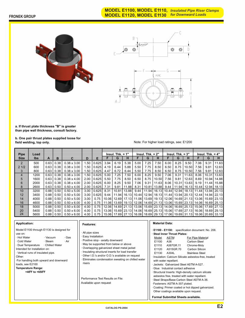
E2
Insulated Pipe Riser Clampsfor Downward Loads
MODEL E1100, MODEL E1110,MODEL E1120, MODEL E1130
Application:
Model E1100 through E1130 is designed for
use on:
· Hot Water · Vacuum · Gas
· Cold Water · Steam · Air
· Dual Temperature · Chilled Water
Intended for installation on:
· Vertical runs of insulated pipe.
Other:
·For handling both upward and downward
loads, see E2100
Temperature Range:
+40oF to +650oF
Available upon request
Features:
· All pipe sizes
· Easy Installation
· Positive stop - axially downward
· May be supported from below or above
· Overlapping galvanized sheet metal jacket
· Insulating structural inserts for load transfer
· Other I.D.'s and/or O.D.'s available on request
· Eliminates condensation sweating on chilled water
risers
Performance Test Results on File:
Material Data:
· E1100 - E1130: specification document: No. 206.
· Steel Inner Thrust Plates:
Model
ASTM
For Pipe Material
E1100 A36 Carbon-Steel
E1110 A387GR.11 Chrome-Moly
E1120 A515GR.70 Carbon Silicon
E1130 A304L Stainless Steel
· Insulation: Calcium Silicate asbestos-free, treated
with water repellant.
· Jackets: Galvanized Steel ASTM A-527.
· Glue: Industrial contact adhesive
· Structural Inserts: High-density calcium silicate
asbestos free, treated with water repellant.
· Steel Straps/Base:Carbon Steel ASTM A-36.
· Fasteners: ASTM A-307 plated.
· Coating: Primer coated or hot dipped galvanized.
Other coatings available upon request.
Formal Submittal Sheets available.
FRONEK GROUP
CATALOG PS-2004
Pipe LoadSize lbs A F G H F G H F G H F G H
2 500 0.63 0.38 1.50 0.625 3.94 6.19 5.38 5.00 7.25 7.50 6.00 8.25 9.50 7.06 9.31 11.632 1/2 600 0.63 0.38 1.50 0.625 4.19 6.44 5.88 5.50 7.75 8.50 6.50 8.75 10.50 7.56 9.81 12.63
3 800 0.63 0.38 1.50 0.625 4.47 6.72 6.44 5.50 7.75 8.50 6.50 8.75 10.50 7.56 9.81 12.634 1200 0.63 0.38 1.50 0.625 5.00 7.25 7.50 6.00 8.25 9.50 7.06 9.31 11.63 8.06 10.31 13.635 1600 0.63 0.38 2.00 0.625 5.50 7.75 8.50 6.50 8.75 10.50 7.56 9.81 12.63 8.69 10.94 14.886 2000 0.63 0.38 2.00 0.625 6.00 8.25 9.50 7.06 9.31 11.63 8.06 10.31 13.63 9.19 11.44 15.888 2600 0.63 0.50 2.00 0.625 7.31 9.81 11.88 8.31 10.81 13.88 9.44 11.94 16.13 10.44 12.94 18.1310 3200 0.88 0.50 3.00 0.625 8.31 10.81 13.88 9.44 11.94 16.13 10.44 12.94 18.13 11.44 13.94 20.1312 3400 0.88 0.50 3.00 0.625 9.44 11.94 16.13 10.44 12.94 18.13 11.44 13.94 20.13 12.44 14.94 22.1314 4000 0.88 0.50 3.00 0.75 10.06 12.69 17.13 11.06 13.69 19.13 12.06 14.69 21.13 13.06 15.69 23.1316 4600 0.88 0.50 4.00 0.75 11.06 13.69 19.13 12.06 14.69 21.13 13.06 15.69 23.13 14.06 16.69 25.1318 5000 0.88 0.50 4.00 0.75 12.06 14.69 21.13 13.06 15.69 23.13 14.06 16.69 25.13 15.06 17.69 27.1320 5400 0.88 0.50 4.00 0.75 13.06 15.69 23.13 14.06 16.69 25.13 15.06 17.69 27.13 16.06 18.69 29.1324 5600 0.88 0.50 4.00 0.75 15.06 17.69 27.13 16.06 18.69 29.13 17.06 19.69 31.13 18.06 20.69 33.13
Note: For higher load ratings, see: E1200
0.50 x 6.000.50 x 6.00
0.50 x 6.000.50 x 6.00
0.50 x 5.000.50 x 5.00
0.50 x 4.000.50 x 5.00
0.38 x 4.000.38 x 4.00
0.38 x 3.000.38 x 3.00
0.38 x 3.000.38 x 3.00
Insul. Thk. = 1" Insul. Thk. = 2" Insul. Thk. = 3" Insul. Thk. = 4"
a. If thrust plate thickness "B" is greater
than pipe wall thickness, consult factory.
b. One pair thrust plates supplied loose for
field welding, top only.
B C D E

E3
Insulated Pipe Riser Clampsfor Downward Loads
MODEL E1200, MODEL E1210,MODEL E1220, MODEL E1230
Application:Model E1200 through E1230 is designed for
use on:
· Hot Water · Vacuum · Gas
· Cold Water · Steam · Air
· Dual Temperature · Chilled Water
Intended for installation on:
· Vertical runs of insulated pipe with
downward load only.
Other:
·For handling both upward and downward
loads, see E2200
Temperature Range:
+40oF to +650oF
Material Data:· E1200 - E1230: specification document: No. 206.
· Steel Inner Thrust Plates:
Model ASTM For Pipe Material
E1200 A36 Carbon-Steel
E1210 A387GR.11 Chrome-Moly
E1220 A515GR.70 Carbon Silicon
E1230 A304L Stainless Steel
· Insulation: Calcium Silicate asbestos-free, treated
with water repellant.
· Jackets: Galvanized Steel ASTM A-527.
· Glue: Industrial contact adhesive
· Structural Inserts: High-density calcium silicate
asbestos free, treated with water repellant.
· Steel Straps/Base:Carbon Steel ASTM A-36.
· Fasteners: ASTM A-307 plated.
· Coating: Primer coated or hot dipped galvanized.
Other coatings available upon request.
Formal Submittal Sheets available.
Features:
· All pipe sizes
· Easy Installation
· Positive stop - axially downward
· May be supported from below or above
· Overlapping galvanized sheet metal jacket
· Insulating structural inserts for load transfer
· Other I.D.'s and/or O.D.'s Available on Request
· Eliminates condensation sweating on chilled
water risers
Performance Test Results on File:
Available upon request
FRONEK GROUP
CATALOG PS-2004
Pipe LoadSize lbs A F G H F G H F G H F G H
2 750 0.63 0.50 1.50 0.625 4.19 6.19 5.63 5.25 7.25 7.75 6.25 8.25 9.75 7.31 9.31 11.882 1/2 900 0.63 0.50 1.50 0.625 4.44 6.44 6.13 5.75 7.75 8.75 6.75 8.75 10.75 7.81 9.81 12.88
3 1200 0.63 0.50 1.50 0.625 4.72 6.72 6.69 5.75 7.75 8.75 6.75 8.75 10.75 7.81 9.81 12.884 1800 0.63 0.50 2.00 0.625 5.25 7.25 7.75 6.25 8.25 9.75 7.31 9.31 11.88 8.31 10.31 13.885 2400 0.63 0.50 2.00 0.625 5.75 7.75 8.75 6.75 8.75 10.75 7.81 9.81 12.88 8.94 10.94 15.136 3000 0.88 0.50 3.00 0.625 6.25 8.25 9.75 7.31 9.31 11.88 8.31 10.31 13.88 9.44 11.44 16.138 3900 0.88 0.50 3.00 0.625 7.31 9.31 11.88 8.31 10.31 13.88 9.44 11.44 16.13 10.44 12.44 18.1310 4800 0.88 0.50 4.00 0.75 8.44 10.69 13.88 9.56 11.81 16.13 10.56 12.81 18.13 11.56 13.81 20.1312 5100 1.13 0.50 4.00 0.75 9.56 11.81 16.13 10.56 12.81 18.13 11.56 13.81 20.13 12.56 14.81 22.1314 6000 1.13 0.50 4.00 0.75 10.06 12.31 17.13 11.06 13.31 19.13 12.06 14.31 21.13 13.06 15.31 23.1316 6900 1.13 0.50 5.00 0.88 11.19 13.44 19.13 12.19 14.44 21.13 13.19 15.44 23.13 14.19 16.44 25.1318 7500 1.13 0.50 5.00 0.88 12.19 14.44 21.13 13.19 15.44 23.13 14.19 16.44 25.13 15.19 17.44 27.1320 8100 1.13 0.50 5.00 0.88 13.19 15.44 23.13 14.19 16.44 25.13 15.19 17.44 27.13 16.19 18.44 29.1324 8400 1.13 0.50 5.00 0.88 15.19 17.69 27.13 16.19 18.69 29.13 17.19 19.69 31.13 18.19 20.69 33.13
Note: For higher load ratings, see: E1300
0.50 x 7.000.50 x 7.00
0.50 x 7.000.50 x 7.00
0.50 x 6.000.50 x 6.00
0.50 x 5.000.50 x 6.00
0.50 x 4.000.50 x 5.00
0.50 x 3.000.50 x 4.00
0.50 x 3.000.50 x 3.00
Insul. Thk. = 1" Insul. Thk. = 2" Insul. Thk. = 3" Insul. Thk. = 4"
a. If thrust plate thickness "B" is greater
than pipe wall thickness, consult factory.
b. One pair thrust plates supplied loose for
field welding, top only.
B C D E
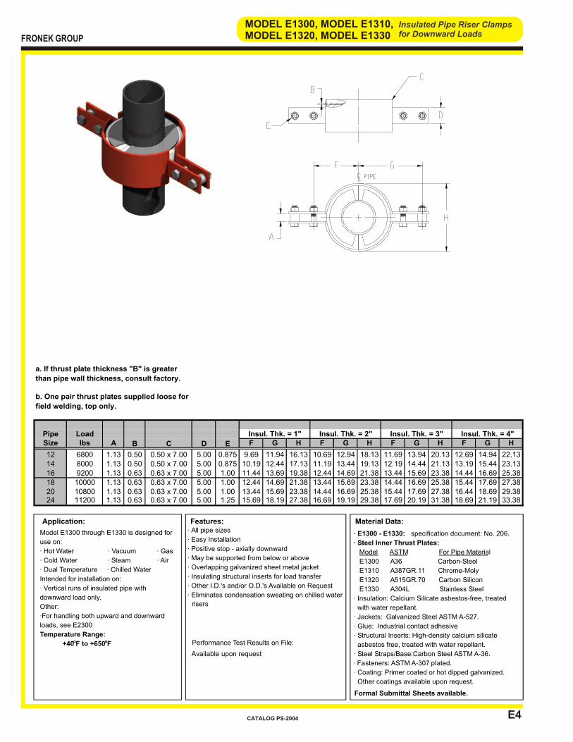
E4
Insulated Pipe Riser Clampsfor Downward Loads
MODEL E1300, MODEL E1310,MODEL E1320, MODEL E1330
Application:
Model E1300 through E1330 is designed for
use on:
· Hot Water · Vacuum · Gas
· Cold Water · Steam · Air
· Dual Temperature · Chilled Water
Intended for installation on:
· Vertical runs of insulated pipe with
downward load only.
Other:
·For handling both upward and downward
loads, see E2300
Temperature Range:
+40oF to +650oF
Material Data:
· E1300 - E1330: specification document: No. 206.
· Steel Inner Thrust Plates:
Model ASTM For Pipe Material
E1300 A36 Carbon-Steel
E1310 A387GR.11 Chrome-Moly
E1320 A515GR.70 Carbon Silicon
E1330 A304L Stainless Steel
· Insulation: Calcium Silicate asbestos-free, treated
with water repellant.
· Jackets: Galvanized Steel ASTM A-527.
· Glue: Industrial contact adhesive
· Structural Inserts: High-density calcium silicate
asbestos free, treated with water repellant.
· Steel Straps/Base:Carbon Steel ASTM A-36.
· Fasteners: ASTM A-307 plated.
· Coating: Primer coated or hot dipped galvanized.
Other coatings available upon request.
Formal Submittal Sheets available.
Features: · All pipe sizes
· Easy Installation
· Positive stop - axially downward
· May be supported from below or above
· Overlapping galvanized sheet metal jacket
· Insulating structural inserts for load transfer
· Other I.D.'s and/or O.D.'s Available on Request
· Eliminates condensation sweating on chilled water
risers
Performance Test Results on File:
Available upon request
FRONEK GROUP
CATALOG PS-2004
Pipe LoadSize lbs A F G H F G H F G H F G H
12 6800 1.13 0.50 5.00 0.875 9.69 11.94 16.13 10.69 12.94 18.13 11.69 13.94 20.13 12.69 14.94 22.1314 8000 1.13 0.50 5.00 0.875 10.19 12.44 17.13 11.19 13.44 19.13 12.19 14.44 21.13 13.19 15.44 23.1316 9200 1.13 0.63 5.00 1.00 11.44 13.69 19.38 12.44 14.69 21.38 13.44 15.69 23.38 14.44 16.69 25.3818 10000 1.13 0.63 5.00 1.00 12.44 14.69 21.38 13.44 15.69 23.38 14.44 16.69 25.38 15.44 17.69 27.3820 10800 1.13 0.63 5.00 1.00 13.44 15.69 23.38 14.44 16.69 25.38 15.44 17.69 27.38 16.44 18.69 29.3824 11200 1.13 0.63 5.00 1.25 15.69 18.19 27.38 16.69 19.19 29.38 17.69 20.19 31.38 18.69 21.19 33.380.63 x 7.00
0.63 x 7.000.63 x 7.00
0.50 x 7.000.63 x 7.00
Insul. Thk. = 4"
0.50 x 7.00
Insul. Thk. = 1" Insul. Thk. = 2" Insul. Thk. = 3"
B C D E
a. If thrust plate thickness "B" is greater
than pipe wall thickness, consult factory.
b. One pair thrust plates supplied loose for
field welding, top only.

E5
Insulated Pipe Riser Clampsfor Upward or Downward Loads
MODEL E2000, MODEL E2010,MODEL E2020, MODEL E2030
Application:
Model E2000 through E2030 is designed for
use on:
· Hot Water · Vacuum · Gas
· Cold Water · Steam · Air
· Dual Temperature · Chilled Water
Intended for installation on:
· Vertical runs of insulated pipe with upward
and/or downward load.
Other:
·For handling downward loads only, see
E1000
Temperature Range:
+40oF to +650oF
Material Data:
· E2000 - E2030: specification document: No. 206.
· Steel Top Thrust Plates:
Model ASTM For Pipe Material
E2000 A36 Carbon-Steel
E2010 A387GR.11 Chrome-Moly
E2020 A515GR.70 Carbon Silicon
E2030 A304L Stainless Steel
· Insulation: Calcium Silicate asbestos-free, treated
with water repellant.
· Jackets: Galvanized Steel ASTM A-527.
· Glue: Industrial contact adhesive
· Structural Inserts: High-density calcium silicate
asbestos free, treated with water repellant.
· Steel Straps/Base:Carbon Steel ASTM A-36.
· Fasteners: ASTM A-307 plated.
· Coating: Primer coated or hot dipped galvanized.
Other coatings available upon request.
Formal Submittal Sheets available.
Features:
· All pipe sizes
· Easy Installation
· Positive stop - axially upward or downward
· May be supported from below or above
· Overlapping galvanized sheet metal jacket
· Insulating structural inserts for load transfer
· Other I.D.'s and/or O.D.'s Available on Request
· Eliminates condensation sweating on chilled
water risers
Performance Test Results on File:
Available upon request
FRONEK GROUP
CATALOG PS-2004
Pipe LoadSize lbs A F G H F G H F G H F G H
2 250 0.63 0.25 1.50 0.625 3.69 5.69 5.13 4.75 6.75 7.25 5.75 7.75 9.25 6.81 8.81 11.382 1/2 300 0.63 0.25 1.50 0.625 3.94 5.94 5.63 5.25 7.25 8.25 6.25 8.25 10.25 7.31 9.31 12.38
3 400 0.63 0.25 1.50 0.625 4.22 6.22 6.19 5.25 7.25 8.25 6.25 8.25 10.25 7.31 9.31 12.384 600 0.63 0.25 1.50 0.625 4.75 6.75 7.25 5.75 7.75 9.25 6.81 8.81 11.38 7.81 9.81 13.385 800 0.63 0.25 1.50 0.625 5.25 7.25 8.25 6.25 8.25 10.25 7.31 9.31 12.38 8.44 10.44 14.636 1000 0.63 0.25 2.00 0.625 5.75 7.75 9.25 6.81 8.81 11.38 7.81 9.81 13.38 8.94 10.94 15.638 1300 0.63 0.25 2.00 0.625 6.81 8.81 11.38 7.81 9.81 13.38 8.94 10.94 15.63 9.94 11.94 17.6310 1600 0.63 0.38 3.00 0.625 8.06 10.31 13.63 9.19 11.44 15.88 10.19 12.44 17.88 11.19 13.44 19.8812 1700 0.63 0.38 3.00 0.625 9.19 11.44 15.88 10.19 12.44 17.88 11.19 13.44 19.88 12.19 14.44 21.8814 2000 0.88 0.38 3.00 0.625 9.69 11.94 16.88 10.69 12.94 18.88 11.69 13.94 20.88 12.69 14.94 22.8816 2300 0.88 0.38 3.00 0.625 10.69 12.94 18.88 11.69 13.94 20.88 12.69 14.94 22.88 13.69 15.94 24.8818 2500 0.88 0.38 3.00 0.625 11.69 13.94 20.88 12.69 14.94 22.88 13.69 15.94 24.88 14.69 16.94 26.8820 2700 0.88 0.38 3.00 0.625 12.69 14.94 22.88 13.69 15.94 24.88 14.69 16.94 26.88 15.69 17.94 28.8824 2800 0.88 0.38 3.00 0.625 14.69 17.19 26.88 15.69 18.19 28.88 16.69 19.19 30.88 17.69 20.19 32.88
Note: For higher load ratings, see: E2100 b. One pair thrust plates supplied loose for field
welding, top and bottom.
a. If thrust plate thickness "B" is greater than pipe
wall thickness, consult factory.
0.38 x 5.00
0.25 x 4.000.38 x 5.00
0.25 x 3.000.25 x 4.00
0.25 x 3.000.25 x 3.00
0.38 x 5.00
0.38 x 5.000.38 x 5.00
0.38 x 5.000.38 x 5.00
0.25 x 3.000.25 x 3.00
Insul. Thk. = 1" Insul. Thk. = 2" Insul. Thk. = 3" Insul. Thk. = 4"
B C D E
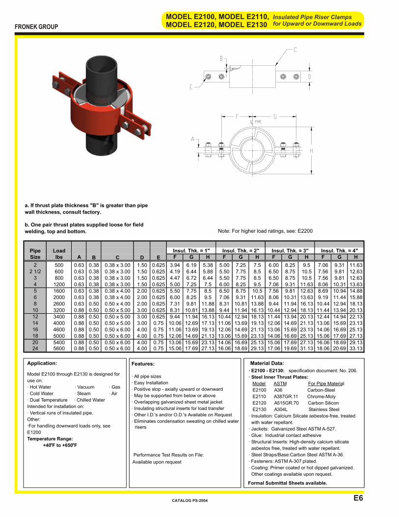
E6
Insulated Pipe Riser Clampsfor Upward or Downward Loads
MODEL E2100, MODEL E2110,MODEL E2120, MODEL E2130
Application:
Model E2100 through E2130 is designed for
use on:
· Hot Water · Vacuum · Gas
· Cold Water · Steam · Air
· Dual Temperature · Chilled Water
Intended for installation on:
· Vertical runs of insulated pipe.
Other:
·For handling downward loads only, see
E1200
Temperature Range:
+40oF to +650oF
Material Data:
· E2100 - E2130: specification document: No. 206.
· Steel Inner Thrust Plates:
Model ASTM For Pipe Material
E2100 A36 Carbon-Steel
E2110 A387GR.11 Chrome-Moly
E2120 A515GR.70 Carbon Silicon
E2130 A304L Stainless Steel
· Insulation: Calcium Silicate asbestos-free, treated
with water repellant.
· Jackets: Galvanized Steel ASTM A-527.
· Glue: Industrial contact adhesive
· Structural Inserts: High-density calcium silicate
asbestos free, treated with water repellant.
· Steel Straps/Base:Carbon Steel ASTM A-36.
· Fasteners: ASTM A-307 plated.
· Coating: Primer coated or hot dipped galvanized.
Other coatings available upon request.
Formal Submittal Sheets available.
Features:
· All pipe sizes
· Easy Installation
· Positive stop - axially upward or downward
· May be supported from below or above
· Overlapping galvanized sheet metal jacket
· Insulating structural inserts for load transfer
· Other I.D.'s and/or O.D.'s Available on Request
· Eliminates condensation sweating on chilled water risers
Performance Test Results on File:
Available upon request
FRONEK GROUP
CATALOG PS-2004
Pipe LoadSize lbs A F G H F G H F G H F G H
2 500 0.63 0.38 1.50 0.625 3.94 6.19 5.38 5.00 7.25 7.5 6.00 8.25 9.5 7.06 9.31 11.632 1/2 600 0.63 0.38 1.50 0.625 4.19 6.44 5.88 5.50 7.75 8.5 6.50 8.75 10.5 7.56 9.81 12.63
3 800 0.63 0.38 1.50 0.625 4.47 6.72 6.44 5.50 7.75 8.5 6.50 8.75 10.5 7.56 9.81 12.634 1200 0.63 0.38 1.50 0.625 5.00 7.25 7.5 6.00 8.25 9.5 7.06 9.31 11.63 8.06 10.31 13.635 1600 0.63 0.38 2.00 0.625 5.50 7.75 8.5 6.50 8.75 10.5 7.56 9.81 12.63 8.69 10.94 14.886 2000 0.63 0.38 2.00 0.625 6.00 8.25 9.5 7.06 9.31 11.63 8.06 10.31 13.63 9.19 11.44 15.888 2600 0.63 0.50 2.00 0.625 7.31 9.81 11.88 8.31 10.81 13.88 9.44 11.94 16.13 10.44 12.94 18.1310 3200 0.88 0.50 3.00 0.625 8.31 10.81 13.88 9.44 11.94 16.13 10.44 12.94 18.13 11.44 13.94 20.1312 3400 0.88 0.50 3.00 0.625 9.44 11.94 16.13 10.44 12.94 18.13 11.44 13.94 20.13 12.44 14.94 22.1314 4000 0.88 0.50 3.00 0.75 10.06 12.69 17.13 11.06 13.69 19.13 12.06 14.69 21.13 13.06 15.69 23.1316 4600 0.88 0.50 4.00 0.75 11.06 13.69 19.13 12.06 14.69 21.13 13.06 15.69 23.13 14.06 16.69 25.1318 5000 0.88 0.50 4.00 0.75 12.06 14.69 21.13 13.06 15.69 23.13 14.06 16.69 25.13 15.06 17.69 27.1320 5400 0.88 0.50 4.00 0.75 13.06 15.69 23.13 14.06 16.69 25.13 15.06 17.69 27.13 16.06 18.69 29.1324 5600 0.88 0.50 4.00 0.75 15.06 17.69 27.13 16.06 18.69 29.13 17.06 19.69 31.13 18.06 20.69 33.13
Note: For higher load ratings, see: E2200
a. If thrust plate thickness "B" is greater than pipe
wall thickness, consult factory.
b. One pair thrust plates supplied loose for field
welding, top and bottom.
0.50 x 6.00
0.50 x 4.000.50 x 5.00
0.38 x 4.000.38 x 4.00
0.38 x 3.000.38 x 3.00
0.50 x 6.00
0.50 x 6.000.50 x 6.00
0.50 x 5.000.50 x 5.00
0.38 x 3.000.38 x 3.00
Insul. Thk. = 1" Insul. Thk. = 2" Insul. Thk. = 3" Insul. Thk. = 4"
B C D E
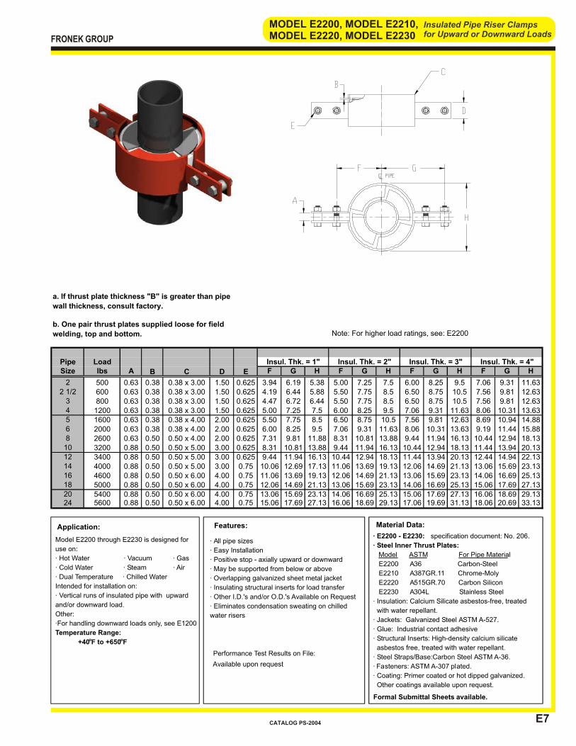
E7
Insulated Pipe Riser Clampsfor Upward or Downward Loads
MODEL E2200, MODEL E2210,MODEL E2220, MODEL E2230
Application:
Model E2200 through E2230 is designed for
use on:
· Hot Water · Vacuum · Gas
· Cold Water · Steam · Air
· Dual Temperature · Chilled Water
Intended for installation on:
· Vertical runs of insulated pipe with upward
and/or downward load.
Other:
·For handling downward loads only, see E1200
Temperature Range:
+40oF to +650oF
Material Data:
· E2200 - E2230: specification document: No. 206.
· Steel Inner Thrust Plates:
Model ASTM For Pipe Material
E2200 A36 Carbon-Steel
E2210 A387GR.11 Chrome-Moly
E2220 A515GR.70 Carbon Silicon
E2230 A304L Stainless Steel
· Insulation: Calcium Silicate asbestos-free, treated
with water repellant.
· Jackets: Galvanized Steel ASTM A-527.
· Glue: Industrial contact adhesive
· Structural Inserts: High-density calcium silicate
asbestos free, treated with water repellant.
· Steel Straps/Base:Carbon Steel ASTM A-36.
· Fasteners: ASTM A-307 plated.
· Coating: Primer coated or hot dipped galvanized.
Other coatings available upon request.
Formal Submittal Sheets available.
Features:
· All pipe sizes
· Easy Installation
· Positive stop - axially upward or downward
· May be supported from below or above
· Overlapping galvanized sheet metal jacket
· Insulating structural inserts for load transfer
· Other I.D.'s and/or O.D.'s Available on Request
· Eliminates condensation sweating on chilled
water risers
Performance Test Results on File:
Available upon request
FRONEK GROUP
CATALOG PS-2004
Pipe LoadSize lbs A F G H F G H F G H F G H
2 500 0.63 0.38 1.50 0.625 3.94 6.19 5.38 5.00 7.25 7.5 6.00 8.25 9.5 7.06 9.31 11.632 1/2 600 0.63 0.38 1.50 0.625 4.19 6.44 5.88 5.50 7.75 8.5 6.50 8.75 10.5 7.56 9.81 12.63
3 800 0.63 0.38 1.50 0.625 4.47 6.72 6.44 5.50 7.75 8.5 6.50 8.75 10.5 7.56 9.81 12.634 1200 0.63 0.38 1.50 0.625 5.00 7.25 7.5 6.00 8.25 9.5 7.06 9.31 11.63 8.06 10.31 13.635 1600 0.63 0.38 2.00 0.625 5.50 7.75 8.5 6.50 8.75 10.5 7.56 9.81 12.63 8.69 10.94 14.886 2000 0.63 0.38 2.00 0.625 6.00 8.25 9.5 7.06 9.31 11.63 8.06 10.31 13.63 9.19 11.44 15.888 2600 0.63 0.50 2.00 0.625 7.31 9.81 11.88 8.31 10.81 13.88 9.44 11.94 16.13 10.44 12.94 18.1310 3200 0.88 0.50 3.00 0.625 8.31 10.81 13.88 9.44 11.94 16.13 10.44 12.94 18.13 11.44 13.94 20.1312 3400 0.88 0.50 3.00 0.625 9.44 11.94 16.13 10.44 12.94 18.13 11.44 13.94 20.13 12.44 14.94 22.1314 4000 0.88 0.50 3.00 0.75 10.06 12.69 17.13 11.06 13.69 19.13 12.06 14.69 21.13 13.06 15.69 23.1316 4600 0.88 0.50 4.00 0.75 11.06 13.69 19.13 12.06 14.69 21.13 13.06 15.69 23.13 14.06 16.69 25.1318 5000 0.88 0.50 4.00 0.75 12.06 14.69 21.13 13.06 15.69 23.13 14.06 16.69 25.13 15.06 17.69 27.1320 5400 0.88 0.50 4.00 0.75 13.06 15.69 23.13 14.06 16.69 25.13 15.06 17.69 27.13 16.06 18.69 29.1324 5600 0.88 0.50 4.00 0.75 15.06 17.69 27.13 16.06 18.69 29.13 17.06 19.69 31.13 18.06 20.69 33.13
Note: For higher load ratings, see: E2200
a. If thrust plate thickness "B" is greater than pipe
wall thickness, consult factory.
b. One pair thrust plates supplied loose for field
welding, top and bottom.
0.50 x 6.00
0.50 x 4.000.50 x 5.00
0.38 x 4.000.38 x 4.00
0.38 x 3.000.38 x 3.00
0.50 x 6.00
0.50 x 6.000.50 x 6.00
0.50 x 5.000.50 x 5.00
0.38 x 3.000.38 x 3.00
Insul. Thk. = 1" Insul. Thk. = 2" Insul. Thk. = 3" Insul. Thk. = 4"
B C D E

E8
Insulated Pipe Riser Clampsfor Upward or Downward Loads
MODEL E2300, MODEL E2310,MODEL E2320, MODEL E2330
Application:
Model E2300 through E2330 is designed for
use on:
· Hot Water · Vacuum · Gas
· Cold Water · Steam · Air
· Dual Temperature · Chilled Water
Intended for installation on:
· Vertical runs of insulated pipe with upward
and/or downward load.
Other:
·For handling downward loads only, see E1300
Temperature Range:
+40oF to +650oF
Material Data:
· E2300 - E2330: specification document: No. 206.
· Steel Inner Thrust Plates:
Model ASTM For Pipe Material
E2300 A36 Carbon-Steel
E2310 A387GR.11 Chrome-Moly
E2320 A515GR.70 Carbon Silicon
E2330 A304L Stainless Steel
· Insulation: Calcium Silicate asbestos-free, treated
with water repellant.
· Jackets: Galvanized Steel ASTM A-527.
· Glue: Industrial contact adhesive
· Structural Inserts: High-density calcium silicate
asbestos free, treated with water repellant.
· Steel Straps/Base:Carbon Steel ASTM A-36.
· Fasteners: ASTM A-307 plated.
· Coating: Primer coated or hot dipped galvanized.
Other coatings available upon request.
Formal Submittal Sheets available.
Features:
· All pipe sizes
· Easy Installation
· Positive stop - axially downward
· May be supported from below or above
· Overlapping galvanized sheet metal jacket
· Insulating structural inserts for load transfer
· Other I.D.'s and/or O.D.'s Available on Request
· Eliminates condensation sweating on chilled water
risers
Performance Test Results on File:
Available upon request
FRONEK GROUP
CATALOG PS-2004
Pipe LoadSize lbs A F G H F G H F G H F G H
12 6800 1.13 0.50 5.00 0.875 9.69 11.94 16.13 10.69 12.94 18.13 11.69 13.94 20.13 12.69 14.94 22.1314 8000 1.13 0.50 5.00 0.875 10.19 12.44 17.13 11.19 13.44 19.13 12.19 14.44 21.13 13.19 15.44 23.1316 9200 1.13 0.63 5.00 1.00 11.44 13.69 19.38 12.44 14.69 21.38 13.44 15.69 23.38 14.44 16.69 25.3818 10000 1.13 0.63 5.00 1.00 12.44 14.69 21.38 13.44 15.69 23.38 14.44 16.69 25.38 15.44 17.69 27.3820 10800 1.13 0.63 5.00 1.00 13.44 15.69 23.38 14.44 16.69 25.38 15.44 17.69 27.38 16.44 18.69 29.3824 11200 1.13 0.63 5.00 1.25 15.69 18.19 27.38 16.69 19.19 29.38 17.69 20.19 31.38 18.69 21.19 33.38
0.50 x 7.00
B
Insul. Thk. = 3" Insul. Thk. = 4"
a. If thrust plate thickness "B" is greater than pipe
wall thickness, consult factory.
b. One pair thrust plates supplied loose for field
welding, top and bottom.
0.63 x 7.000.63 x 7.00
0.63 x 7.000.63 x 7.00
0.50 x 7.00
C D E
Insul. Thk. = 1" Insul. Thk. = 2"

INTRODUCTION SECTION “G”
INTRODUCTION
SECTION “G”
PIPE CLAMPS, PIPE GUIDE STRAPS, PIPE GUIDE U-BOLTS
APPLICATION – For installation on standard 1-5/8” width framing channel. The models listed in the Section Index are selected based upon the following considerations:
FOR USE WITH Bare Pipe Copper Tubing Insulated Pipe Support PURPOSE Clamp Guide DUTY Light Heavy
If your requirements are not covered by the Product Data Sheets in this catalog, please contact us at
713-731-0030 or 1-800-787-5914.
Please acquaint yourself with the Section Index on the page following this introduction for assistance in determining the most appropriate pipe clamp, pipe guide strap, or pipe guide
U-bolt for your application
FRONEK GROUP
CATALOG PS-2004

BAREBARE COPPER INSULATED
MODEL PIPE TUBING PIPE SUPPORT CLAMP GUIDE DUTY
G1000 X X X LIGHT
G1200 X X X LIGHT
X X
HEAVY
G2000 X X
G2200 X X X HEAVY
G3000 X X X LIGHT
FOR USE ON
PIPE CLAMPS, PIPE GUIDE STRAPS, PIPE GUIDE U-BOLTS
PURPOSE
SECTION “G” INDEX
TO ORDER, specify:1. Quantity 202. Pipe Size & Type 2” IPS3. Insulation Thickness 2-1/2”4. Model Number G10005. For use on (bare pipe or insulated pipe support model) A1000
EXAMPLE: (20) 2 x 2-1/2 G1000 (For use on A1000)
FRONEK GROUP
CATALOG PS-2004
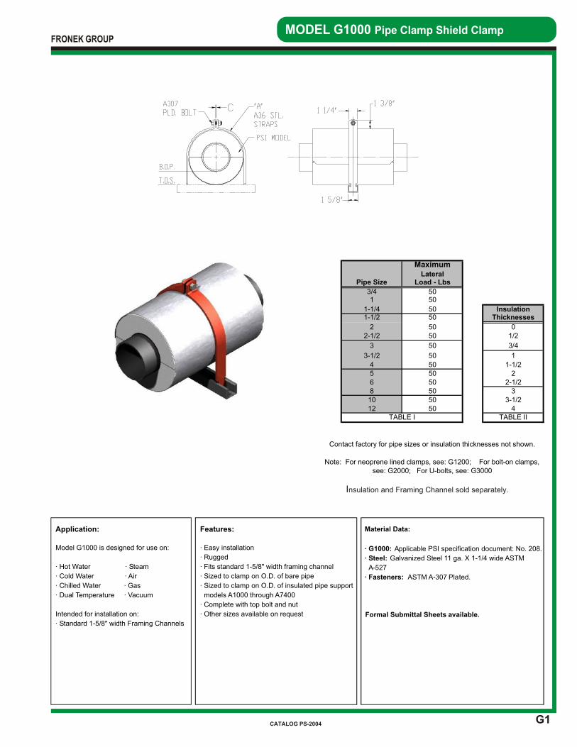
G1
MODEL G1000 Pipe Clamp Shield Clamp
Application:
Model G1000 is designed for use on:
· Hot Water · Steam
· Cold Water · Air
· Chilled Water · Gas
· Dual Temperature · Vacuum
Intended for installation on:
· Standard 1-5/8" width Framing Channels
Features:
· Easy installation
· Rugged
· Fits standard 1-5/8" width framing channel
· Sized to clamp on O.D. of bare pipe
· Sized to clamp on O.D. of insulated pipe support
models A1000 through A7400
· Complete with top bolt and nut
· Other sizes available on request
Material Data:
· G1000: Applicable PSI specification document: No. 208.
· Steel: Galvanized Steel 11 ga. X 1-1/4 wide ASTM
A-527
· Fasteners: ASTM A-307 Plated.
Formal Submittal Sheets available.
Insulation and Framing Channel sold separately.
FRONEK GROUP
CATALOG PS-2004
MaximumLateral
Pipe Size Load - Lbs
3/4 501 50
1-1/4 50 Insulation1-1/2 50 Thicknesses
2 50 02-1/2 50 1/2
3 50 3/4
3-1/2 50 1
4 50 1-1/25 50 26 50 2-1/28 50 310 50 3-1/212 50 4
Note: For neoprene lined clamps, see: G1200; For bolt-on clamps, see: G2000; For U-bolts, see: G3000
TABLE I TABLE II
Contact factory for pipe sizes or insulation thicknesses not shown.
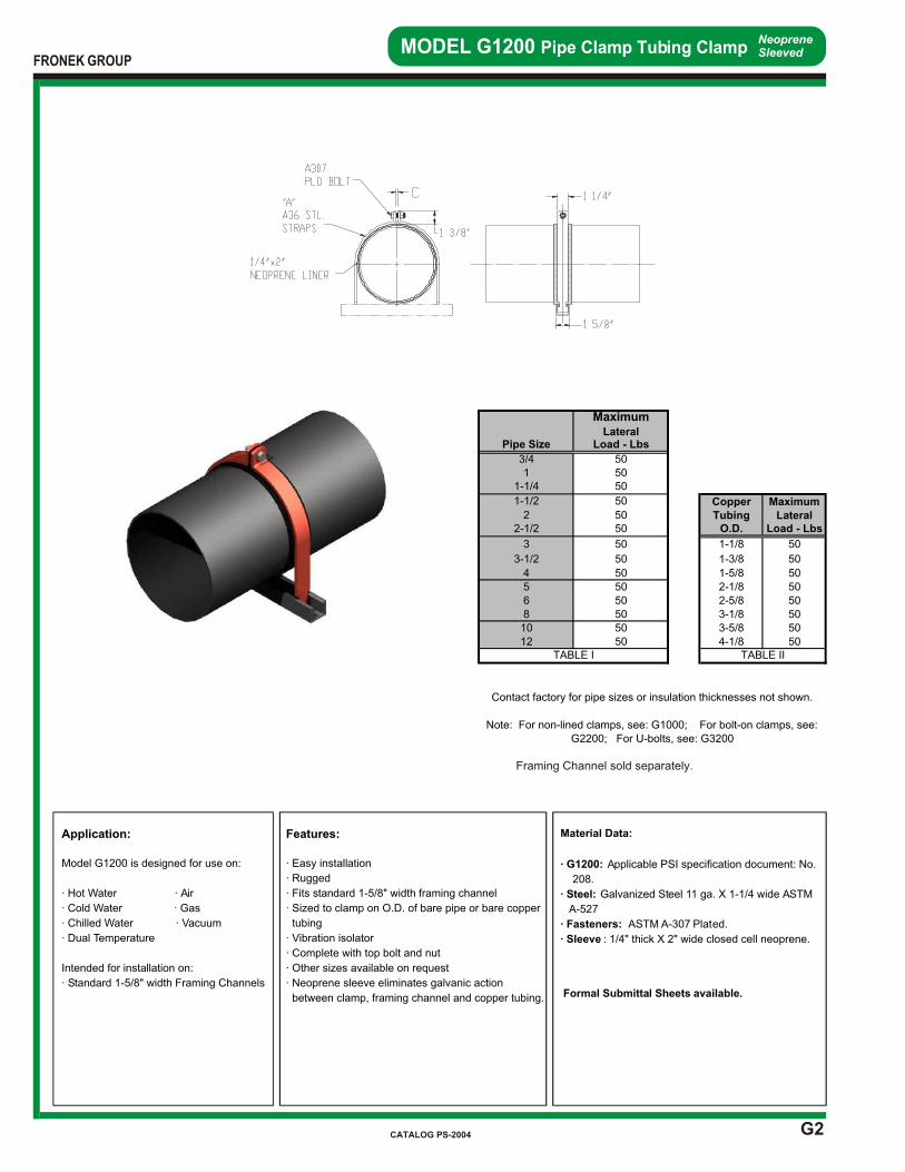
G2
MODEL G1200 Pipe Clamp Tubing ClampNeopreneSleeved
Application:
Model G1200 is designed for use on:
· Hot Water · Air
· Cold Water · Gas
· Chilled Water · Vacuum
· Dual Temperature
Intended for installation on:
· Standard 1-5/8" width Framing Channels
Features:
· Easy installation
· Rugged
· Fits standard 1-5/8" width framing channel
· Sized to clamp on O.D. of bare pipe or bare copper
tubing
· Vibration isolator
· Complete with top bolt and nut
· Other sizes available on request
· Neoprene sleeve eliminates galvanic action
between clamp, framing channel and copper tubing.
Material Data:
· G1200: Applicable PSI specification document: No.
208.
· Steel: Galvanized Steel 11 ga. X 1-1/4 wide ASTM
A-527
· Fasteners: ASTM A-307 Plated.
· Sleeve : 1/4" thick X 2" wide closed cell neoprene.
Formal Submittal Sheets available.
Framing Channel sold separately.
FRONEK GROUP
CATALOG PS-2004
MaximumLateral
Pipe Size Load - Lbs
3/4 501 50
1-1/4 50
1-1/2 50 Copper Maximum2 50 Tubing Lateral
2-1/2 50 O.D. Load - Lbs
3 50 1-1/8 50
3-1/2 50 1-3/8 50
4 50 1-5/8 505 50 2-1/8 506 50 2-5/8 508 50 3-1/8 5010 50 3-5/8 5012 50 4-1/8 50
TABLE I TABLE II
Contact factory for pipe sizes or insulation thicknesses not shown.
Note: For non-lined clamps, see: G1000; For bolt-on clamps, see: G2200; For U-bolts, see: G3200
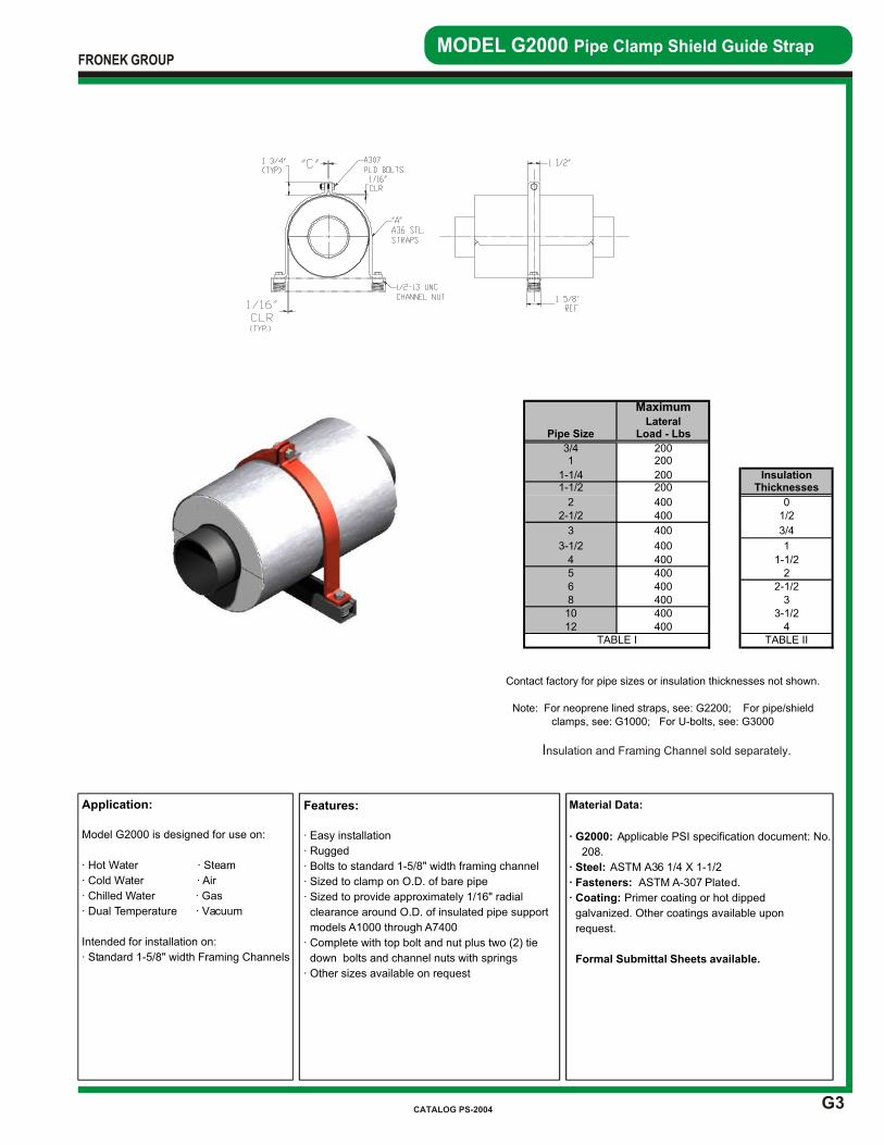
G3
MODEL G2000 Pipe Clamp Shield Guide Strap
Application:
Model G2000 is designed for use on:
· Hot Water · Steam
· Cold Water · Air
· Chilled Water · Gas
· Dual Temperature · Vacuum
Intended for installation on:
· Standard 1-5/8" width Framing Channels
Features:
· Easy installation
· Rugged
· Bolts to standard 1-5/8" width framing channel
· Sized to clamp on O.D. of bare pipe
· Sized to provide approximately 1/16" radial
clearance around O.D. of insulated pipe support
models A1000 through A7400
· Complete with top bolt and nut plus two (2) tie
down bolts and channel nuts with springs
· Other sizes available on request
Material Data:
· G2000: Applicable PSI specification document: No.
208.
· Steel: ASTM A36 1/4 X 1-1/2
· Fasteners: ASTM A-307 Plated.
· Coating: Primer coating or hot dipped
galvanized. Other coatings available upon
request.
Formal Submittal Sheets available.
Insulation and Framing Channel sold separately.
FRONEK GROUP
CATALOG PS-2004
MaximumLateral
Pipe Size Load - Lbs
3/4 2001 200
1-1/4 200 Insulation1-1/2 200 Thicknesses
2 400 02-1/2 400 1/2
3 400 3/4
3-1/2 400 1
4 400 1-1/25 400 26 400 2-1/28 400 310 400 3-1/212 400 4
Note: For neoprene lined straps, see: G2200; For pipe/shield clamps, see: G1000; For U-bolts, see: G3000
TABLE I TABLE II
Contact factory for pipe sizes or insulation thicknesses not shown.
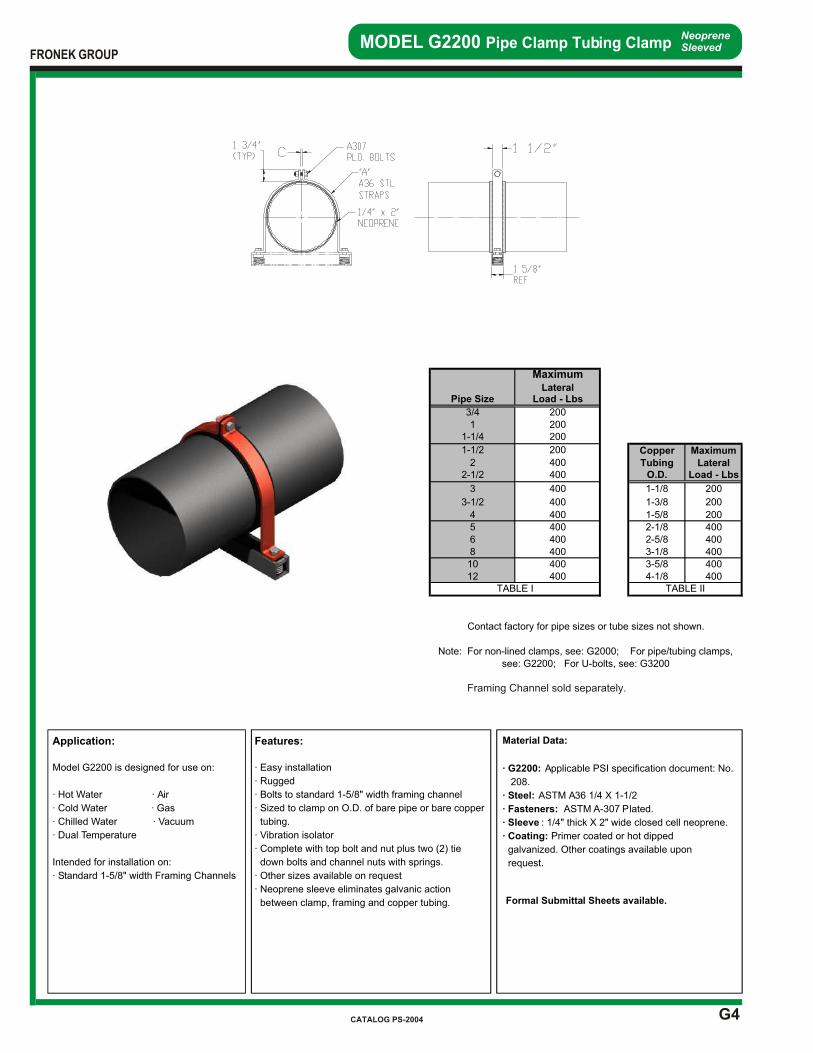
G4
MODEL G2200 Pipe Clamp Tubing ClampNeopreneSleeved
Application:
Model G2200 is designed for use on:
· Hot Water · Air
· Cold Water · Gas
· Chilled Water · Vacuum
· Dual Temperature
Intended for installation on:
· Standard 1-5/8" width Framing Channels
Features:
· Easy installation
· Rugged
· Bolts to standard 1-5/8" width framing channel
· Sized to clamp on O.D. of bare pipe or bare copper
tubing.
· Vibration isolator
· Complete with top bolt and nut plus two (2) tie
down bolts and channel nuts with springs.
· Other sizes available on request
· Neoprene sleeve eliminates galvanic action
between clamp, framing and copper tubing.
Framing Channel sold separately.
Material Data:
· G2200: Applicable PSI specification document: No.
208.
· Steel: ASTM A36 1/4 X 1-1/2
· Fasteners: ASTM A-307 Plated.
· Sleeve : 1/4" thick X 2" wide closed cell neoprene.
· Coating: Primer coated or hot dipped
galvanized. Other coatings available upon
request.
Formal Submittal Sheets available.
FRONEK GROUP
CATALOG PS-2004
MaximumLateral
Pipe Size Load - Lbs
3/4 2001 200
1-1/4 200
1-1/2 200 Copper Maximum2 400 Tubing Lateral
2-1/2 400 O.D. Load - Lbs
3 400 1-1/8 200
3-1/2 400 1-3/8 200
4 400 1-5/8 2005 400 2-1/8 4006 400 2-5/8 4008 400 3-1/8 40010 400 3-5/8 40012 400 4-1/8 400
TABLE I TABLE II
Contact factory for pipe sizes or tube sizes not shown.
Note: For non-lined clamps, see: G2000; For pipe/tubing clamps, see: G2200; For U-bolts, see: G3200
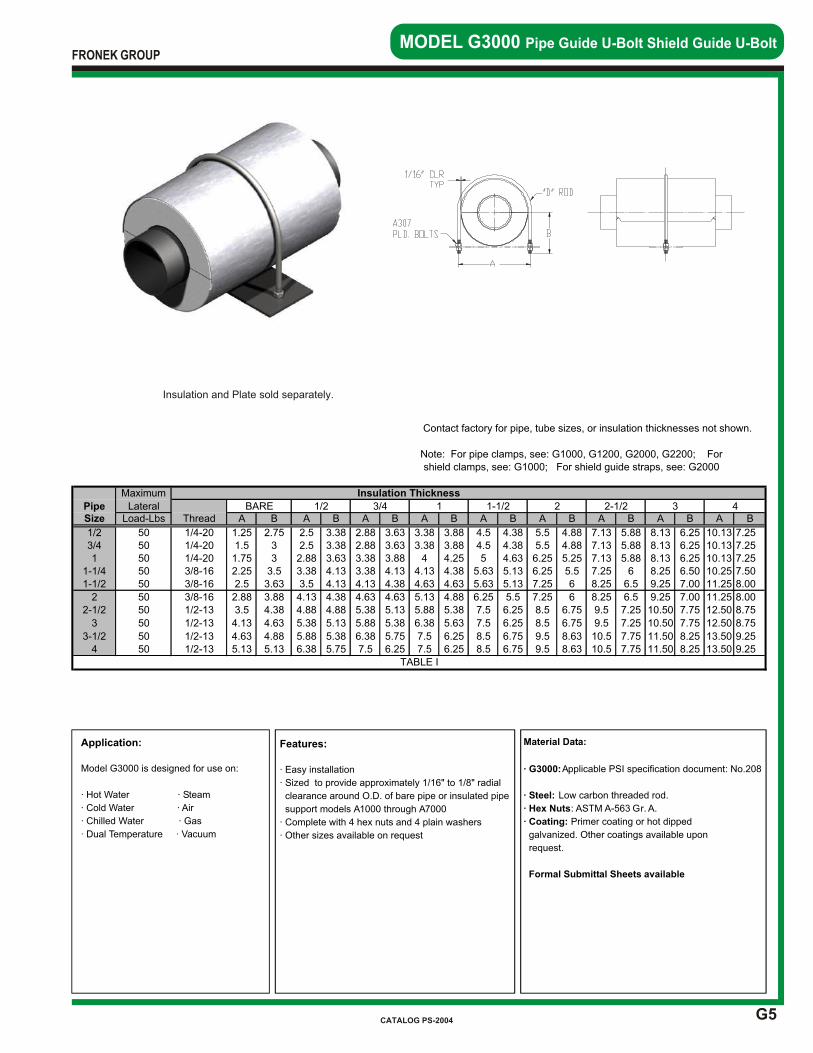
G5
MODEL G3000 Pipe Guide U-Bolt Shield Guide U-Bolt
Application:
Model G3000 is designed for use on:
· Hot Water · Steam
· Cold Water · Air
· Chilled Water · Gas
· Dual Temperature · Vacuum
Features:
· Easy installation
· Sized to provide approximately 1/16" to 1/8" radial
clearance around O.D. of bare pipe or insulated pipe
support models A1000 through A7000
· Complete with 4 hex nuts and 4 plain washers
· Other sizes available on request
Material Data:
· G3000: Applicable PSI specification document: No.208
· Steel: Low carbon threaded rod.
· Hex Nuts: ASTM A-563 Gr. A.
· Coating: Primer coating or hot dipped
galvanized. Other coatings available upon
request.
Formal Submittal Sheets available
Insulation and Plate sold separately.
FRONEK GROUP
CATALOG PS-2004
PipeSize A B A B A B A B A B A B A B A B A B
1/2 1.25 2.75 2.5 3.38 2.88 3.63 3.38 3.88 4.5 4.38 5.5 4.88 7.13 5.88 8.13 6.25 10.13 7.253/4 1.5 3 2.5 3.38 2.88 3.63 3.38 3.88 4.5 4.38 5.5 4.88 7.13 5.88 8.13 6.25 10.13 7.251 1.75 3 2.88 3.63 3.38 3.88 4 4.25 5 4.63 6.25 5.25 7.13 5.88 8.13 6.25 10.13 7.25
1-1/4 2.25 3.5 3.38 4.13 3.38 4.13 4.13 4.38 5.63 5.13 6.25 5.5 7.25 6 8.25 6.50 10.25 7.501-1/2 2.5 3.63 3.5 4.13 4.13 4.38 4.63 4.63 5.63 5.13 7.25 6 8.25 6.5 9.25 7.00 11.25 8.00
2 2.88 3.88 4.13 4.38 4.63 4.63 5.13 4.88 6.25 5.5 7.25 6 8.25 6.5 9.25 7.00 11.25 8.002-1/2 3.5 4.38 4.88 4.88 5.38 5.13 5.88 5.38 7.5 6.25 8.5 6.75 9.5 7.25 10.50 7.75 12.50 8.75
3 4.13 4.63 5.38 5.13 5.88 5.38 6.38 5.63 7.5 6.25 8.5 6.75 9.5 7.25 10.50 7.75 12.50 8.75
3-1/2 4.63 4.88 5.88 5.38 6.38 5.75 7.5 6.25 8.5 6.75 9.5 8.63 10.5 7.75 11.50 8.25 13.50 9.254 5.13 5.13 6.38 5.75 7.5 6.25 7.5 6.25 8.5 6.75 9.5 8.63 10.5 7.75 11.50 8.25 13.50 9.25
Contact factory for pipe, tube sizes, or insulation thicknesses not shown.
Maximum Insulation Thickness
1/2 3/4
Note: For pipe clamps, see: G1000, G1200, G2000, G2200; For shield clamps, see: G1000; For shield guide straps, see: G2000
3 42 2-1/2Load-Lbs Thread
1 1-1/2Lateral BARE
50 1/4-2050 1/4-2050 1/4-2050 3/8-1650 3/8-16
50 3/8-1650 1/2-13
50 1/2-13
50 1/2-1350 1/2-13
TABLE I