pipe rehabilitation with polyethylene pipe liners...
TRANSCRIPT

r
I : :
PIPE REBABILITATIOH WITH POLYETBYLERE PIPE LIRERS
Construction Report for Iowa Highway Rese,arch Board
Project BR-370
March 1995
Project Development Division
Iowa Depa·rtment of Transportation

Construction Report Iowa Highway Research Board
Project HR-370
-------------------
PIPE REHABILITATION WITH POLYETHYLENE PIPE LINERS
By Shane Tymkowicz
Secondary Road Research Coordinator 515-239-1382
Office of Materials Project Development Division
Iowa Department of Transportation Ames, Iowa 50010
March 1995

TECHNICAL REPORT TITLE PAGE
1. REPORT NO.
HR-370
3. TITLE AND SUBTITLE
Pipe Rehabilitation With Polyethylene Pipe Liners
5. AUTBOR(S)
Shane Tymkowicz Secondary Road Research Coordinator
2. REPORT DATE
March 1995
4. TYPE OF REPORT & PERIOD COVERED
Construction Report 6-94 to 3-95
6. PERFORMING ORGANIZATION ADDRESS
Iowa Department of Transportation Materials Department 800 Lincoln Way Ames, Iowa 50010
7. ACKNOWLEDGEMENT OF COOPERATING ORGANIZATIONS
This research was initiated through the Iowa Highway Research Board. Dallas County Secondary Roads Department Jefferson County Secondary Roads Department Jones County Secondary Roads Department Mahaska County Highway Department Taylor County Secondary Roads Department
8. ABSTRACT
Corroded, deteriorated, misaligned, and distorted drainage pipes can cause a serious threat to a roadway. Normal practice is to remove and replace the damaged drainage structure. An alternative method of rehabilitating these structures is to slip line them with a polyethylene liner.
Twelve drainage structures were slip lined with polyethylene liners during 1994 in Iowa. Two types of liners installed were "Culvert Renew" and "Snap-Tite". It was found that the liners could be easily installed by most highway, county, and city maintenance departments. The liners restore the flow and increase the service life of the original drainage structure. The liners were found to be cost competitive with the removal and replacement of the existing drainage structure. Slip lining has the largest economic benefit when the roadway is paved, the culvert is under a deep fill, or traffic volumes are high. The annular space between the original pipe and the liner was filled with flowable mortar. Care should be taken to properly brace and grout the annular space between the liner and the culvert.
9. KEY WORDS Culvert Pipe Rehabilitation Plastic Pipe Polyethylene Liner Slip Lining
10. NO. OF PAGES
55

TABLE OF CONTENTS
Page
Introduction . . . . . . . . . . . . . . . . . . . . . . . . . . . . . . . . . . . . . . . . . . . . . . . 1
Objective . . . . . . . . . . . . . . . . . . . . . . . . . . . . . . . . . . . . . . . . . . . . . . . . 1
Project Locations and Descriptions . . . . . . . . . . . . . . . . . . . . . . . . . . . . . . . . . 2
Research Funded Installations . . . . . . . . . . . . . . . . . . . . . . . . . . . . . . . . . . . . 2 Dallas County . . . . . . . . . . . . . . . . . . . . . . . . . . . . . . . . . . . . . . . . . . . 2 Jefferson County .......................................... 4 Jones County . . . . . . . . . . . . . . . . . . . . . . . . . . . . . . . . . . . . . . . . . . . . 6 Mahaska County .......................................... 9 Taylor County . . . . . . . . . . . . . . . . . . . . . . . . . . . . . . . . . . . . . . . . . . 11
Installations Without Research Funding . . . . . . . . . . . . . . . . . . . . . . . . . . . . . 12 Audubon County . . . . . . . . . . . . . . . . . . . . . . . . . . . . . . . . . . . . . . . . . 12 Crawford County . . . . . . . . . . . . . . . . . . . . . . . . . . . . . . . . . . . . . . . . 13 Henry County, Geode Park . . . . . . . . . . . . . . . . . . . . . . . . . . . . . . . . . . 14 Jones County . . . . . . . . . . . . . . . . . . . . . . . . . . . . . . . . . . . . . . . . . . . 14 Mahaska County . . . . . . . . . . . . . . . . . . . . . . . . . . . . . . . . . . . . . . . . . 14 Pottawattamie County . . . . . . . . . . . . . . . . . . . . . . . . . . . . . . . . . . . . . . 15
General Installation Procedure . . . . . . . . . . . . . . . . . . . . . . . . . . . . . . . . . . . 15 Clean the Existing Culvert . . . . . . . . . . . . . . . . . . . . . . . . . . . . . . . . . . . 15 Prepare the Work Area . . . . . . . . . . . . . . . . . . . . . . . . . . . . . . . . . . . . . 15 Prepare Access Points for Grouting . . . . . . . . . . . . . . . . . . . . . . . . . . . . . 16 Inserting a Cable Through the Culvert . . . . . . . . . . . . . . . . . . . . . . . . . . . . 16 Pulling Head or Nose Cone . . . . . . . . . . . . . . . . . . . . . . . . . . . . . . . . . . 17 Assembling the Culvert . . . . . . . . . . . . . . . . . . . . . . . . . . . . . . . . . . . . . 17 Grouting . . . . . . . . . . . . . . . . . . . . . . . . . . . . . . . . . . . . . . . . . . . . . . 18 Headwalls .......... · . . . . . . . . . . . . . . . . . . . . . . . . . . . . . . . . . . . . 18
Considerations for Grouting . . . . . . . . . . . . . . . . . . . . . . . . . . . . . . . . . . . . 18
Bracing ................................................ 20
Flow Capacity . . . . . . . . . . . . . . . . . . . . . . . . . . . . . . . . . . . . . . . . . . . . 21
Evaluation . . . . . . . . . . . . . . . . . . . . . . . . . . . . . . . . . . . . . . . . . . . . . . . 22

------------------------------------------------
TABLE OF CONTENTS (CONT'D)
Page
Criteria for Using Polyethyelene . . . . . . . . . . . . . . . . . . . . . . . . . . . . . . . . . 22 Acid Conditions . . . . . . . . . . . . . . . . . . . . . . . . . . . . . . . . . . . . . . . . . 22 Deep Fill Sections and High Traffic . . . . . . . . . . . . . . . . . . . . . . . . . . . . . 22 Cost of Slip Lining . . . . . . . . . . . . . . . . . . . . . . . . . . . . . . . . . . . . . . . 23 Public Relations . . . . . . . . . . . . . . . . . . . . . . . . . . . . . . . . . . . . . . . . . 23 Pipe Alignment . . . . . . . . . . . . . . . . . . . . . . . . . . . . . . . . . . . . . . . . . . 23
Discussion . . . . . . . . . . . . . . . . . . . . . . . . . . . . . . . . . . . . . . . . . . . . . . . 24
Acknowledgements . . . . . . . . . . . . . . . . . . . . . . . . . . . . . . . . . . . . . . . . . 25
References . . . . . . . . . . . . . . . . . . . . . . . . . . . . . . . . . . . . . . . . . . . . . . 25
Appendices Appendix A - Maps . . . . . . . . . . . . . . . . . . . . . . . . . . . . . . . . . . . . . . . 26 Appendix B - Photos . . . . . . . . . . . . . . . . . . . . . . . . . . . . . . . . . . . . . . 36 Appendix C - Cost Comparisons . . . . . . . . . . . . . . . . . . . . . . . . . . . . . . . 45 Appendix D- Manning's Equation .............................. 49 Appendix E - Grout Design . . . . . . . . . . . . . . . . . . . . . . . . . . . . . . . . . . 51 Appendix F - Specification Committee Letters . . . . . . . . . . . . . . . . . . . . . . . 53
DISCLAIMER
The contents of this report reflect the views of the author and do not necessarily reflect the official views of the Iowa Department of Transportation. This report does not constitute any standard, specification or regulation.

INTRODUCTION
Corroded, deteriorated, misaligned, and distorted drainage pipes can cause a reduction in
flow or a loss of roadbed material into the pipe. These problems have the potential to be a
serious threat to a roadway. The normal practice is to remove the damaged drainage pipe
and install a new drainage structure. This practice causes considerable disruption to traffic
since removal of the damaged drainage pipe and installation of a new pipe requires an open
trench across the roadway. Also, the procedure has the risk of possible settlement problems.
An alternative method of rehabilitating damaged drainage culverts is slip lining with a
polyethylene liner. Slip lining is the insertion of a prefabricated pipe inside the existing
culvert. The liner can restore the flow volume, and it provides an extended service life for
the existing culvert. Additionally, the technique of slip lining allows the roadway to remain
open to traffic, and it negates the risk of settlement that may occur with the removal and
installation of a new drainage pipe. The slip lining technique may have economic savings
when it is compared with the removal of the old drainage structure and installation of a new
drainage structure.
OBJECTIVES
The objective of the proposed research is to demonstrate and evaluate the applicability of the
pipe lining technique. Specific topics to be researched include:
1. The cost savings of rehabilitating roadway pipe with polyethylene liners.
2. The performance of polyethylene liners in the field.
3. The construction technique used in rehabilitating pipe with polyethylene liners.
1

---------------------,
PROJECT LOCATIONS AND DESCRIPTIONS
There were twelve drainage structures slip lined with polyethylene pipe across the state of
Iowa in 1994. Six of these culvert lining projects were partially funded by this research
project. The installation of these liners are presented in detail. The other six projects were
installed without any research funds by the roadway's governing agency. These projects are
presented with as much information as is known by the author. The projects will be split
into the two categories of "Research Funded Installations" and "Installations Without
Research Funding." The projects in each category will be presented in alphabetical order
according to the county of installation.
The polyethylene pipe liners that were used are "Culvert Renew" and "Snap-Tite." "Culvert
Renew" is a profile wall, smooth interior and exterior, high density polyethylene pipe with a
threaded joint coupling system known as "-Thread-Loc." "Snap-Tite" is a solid wall, smooth
interior and exterior, high density polyethylene pipe with an interlocking mechanical joint.
RESEARCH FUNDED INSTALLATIONS
Dallas County
The project site is 3.5 km (2.2 mi.) west of county road P58 on county road F51 (see map,
page 27). The existing pipe was a 900 mm (36 in.) diameter corrugated metal pipe (CMP)
with a length of 32 m (105 ft.). The bottom quarter of the pipe was unsound due to
corrosion.
2

The installation of the liner took place on June 22, 1994. The product used for the
installation was "Culvert Renew." The liner had an inner diameter (ID) of 760 mm
(30.0 in.), an outer diameter of 860 mm (33.8 in.), and a length of 32 m (105 ft.). It was
delivered to the project site in five 6.1 m (20 ft.) sections and one 1.5 m (5 ft.) section.
Liner installation began by excavating an assembly area beyond the north end of the pipe.
An area about 8 m long (26ft.) long and 1.5 m (5 ft.) wide was cleared, so the pipe could
be assembled in the ditch and inserted at the same alignment as the pipe inlet. Earth was
removed to expose the CMP approximately 1.2 m (4ft.) from the north end and 3.7 m
(12 ft.) from the south end. At the points of exposure, grout holes approximately 100 mm
(4 in.) in diameter were cut with a torch into the top of the CMP.
Installation of the liner began with the 1.5 m (5 ft.) section being inserted into the CMP.
About 0.6 m (2 ft.) of liner was left out of the existing CMP. The next section was lowered
into place. The section was suspended slightly off the ground by a chain attached to the
bucket of a backhoe. A laborer used a chain and a steel bar to thread the new liner section
on. An aluminum plate was placed against the end of the liner. The bucket of the backhoe
pushed against the plate until 0.6 m (2 ft.) of liner was left out of the existing CMP. This
process was repeated until the culvert was lined.
The annular space was pressure grouted with a flowable mortar from both ends and at the
grout holes cut into the top of the pipe. The pressure from the grouting caused the liner to
float to the top of the CMP. Approximately 2.5 m3 (3.3 cu. yds.) of flowable mortar were
used.
3

The installation took four hours. One backhoe operator (4 hours), two laborers (4 hours
each), and one welder (1 hour), for torch work, were required. The equipment used for
lifting and inserting the culvert liner was a Case 580K backhoe. Expenses for slip lining the
culvert and estimated expenses for replacing the culvert are on page 46 in Appendix C.
Jefferson County
The project site is 0.3 km (0.2 mi.) east of Umber Avenue on 195th Street (see map,
page 28). The existing drainage structure was a 1.1 m (3.5 ft.) square wood box culvert (see
photo 1, page 37) with a length of approximately 11 m (35 ft.). The wood had deteriorated,
and granular material from the roadway was falling through the top of the culvert.
Installation of the liner took place on August 24, 1994. The product used for the installation
was "Snap-Tite." The liner has an ID of 760 mm (30.0 in.), an OD of 810 mm (32.0 in.),
and a length of 18 m (60ft.). The pipe was delivered to the project in two segments.
The box culvert was prepared for lining. The foreslopes were cleared of brush. Wingwalls
were removed from the north end of the culvert. Five timber braces were placed along the
top of the wooden box culvert to prevent the liner from floating when the annular space was
filled with flowable mortar. Braces were placed at each end of the culvert and approximately
at each quarter point. The braces were made of 150 mm by 150 mm (6 in. by 6 in.) pieces
of lumber.
4
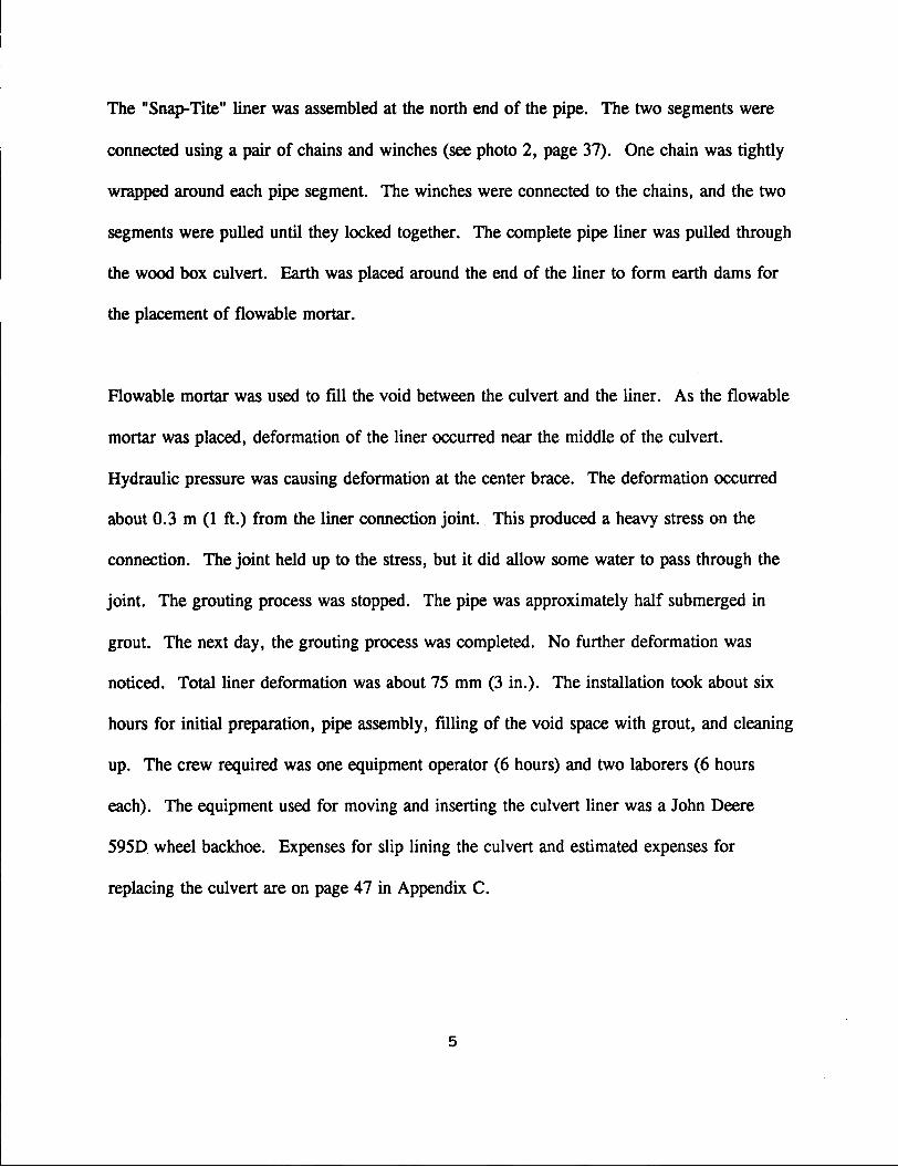
The "Snap-Tite" liner was assembled at the north end of the pipe. The two segments were
connected using a pair of chains and winches (see photo 2, page 37). One chain was tightly
wrapped around each pipe segment. The winches were connected to the chains, and the two
segments were pulled until they locked together. The complete pipe liner was pulled through
the wood box culvert. Earth was placed around the end of the liner to form earth dams for
the placement of flowable mortar.
Plowable mortar was used to fill the void between the culvert and the liner. As the flowable
mortar was placed, deformation of the liner occurred near the middle of the culvert.
Hydraulic pressure was causing deformation at the center brace. The deformation occurred
about 0.3 m (1 ft.) from the liner connection joint. This produced a heavy stress on the
connection. The joint held up to the stress, but it did allow some water to pass through the
joint. The grouting process was stopped. The pipe was approximately half submerged in
grout. The next day, the grouting process was completed. No further deformation was
noticed. Total liner deformation was about 75 mm (3 in.). The installation took about six
hours for initial preparation, pipe assembly, filling of the void space with grout, and cleaning
up. The crew required was one equipment operator (6 hours) and two laborers (6 hours
each). The equipment used for moving and inserting the culvert liner was a John Deere
5950 wheel backhoe. Expenses for slip lining the culvert and estimated expenses for
replacing the culvert are on page 47 in Appendix C.
5
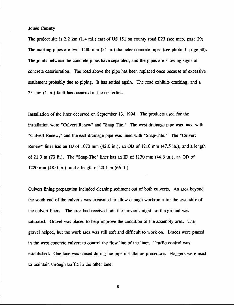
Jones County
The project site is 2.2 km (1.4 mi.) east of US 151 on county road E23 (see map, page 29).
The existing pipes are twin 1400 mm (54 in.) diameter concrete pipes (see photo 3, page 38).
The joints between the concrete pipes have separated, and the pipes are showing signs of
concrete deterioration. The road above the pipe has been replaced once because of excessive
settlement probably due to piping. It has settled again. The road exhibits cracking, and a
25 mm (1 in.) fault has occurred at the centerline.
Installation of the liner occurred on September 13, 1994. The products used for the
installation were "Culvert Renew" and "Snap-Tite." The west drainage pipe was lined with
"Culvert Renew," and the east drainage pipe was lined with "Snap-Tite." The "Culvert
Renew" liner had an ID of 1070 mm (42.0 in.), an OD of 1210 mm (47.5 in.), and a length
of 21.3 m (70ft.). The "Snap-Tite" liner has an ID of 1130 mm (44.3 in.), an OD of
1220 mm (48.0 in.), and a length of 20.1 m (66 ft.).
Culvert lining preparation included cleaning sediment out of both culverts. An area beyond
the south end of the culverts was excavated to allow enough workroom for the assembly of
the culvert liners. The area had received rain the previous night, so the ground was
saturated. Gravel was placed to help improve the condition of the assembly area. The
gravel helped, but the work area was still soft and difficult to work on. Braces were placed
in the west concrete culvert to control the flow line of the liner. Traffic control was
established. One lane was closed during the pipe installation procedure. Flaggers were used
to maintain through traffic in the other lane.
6
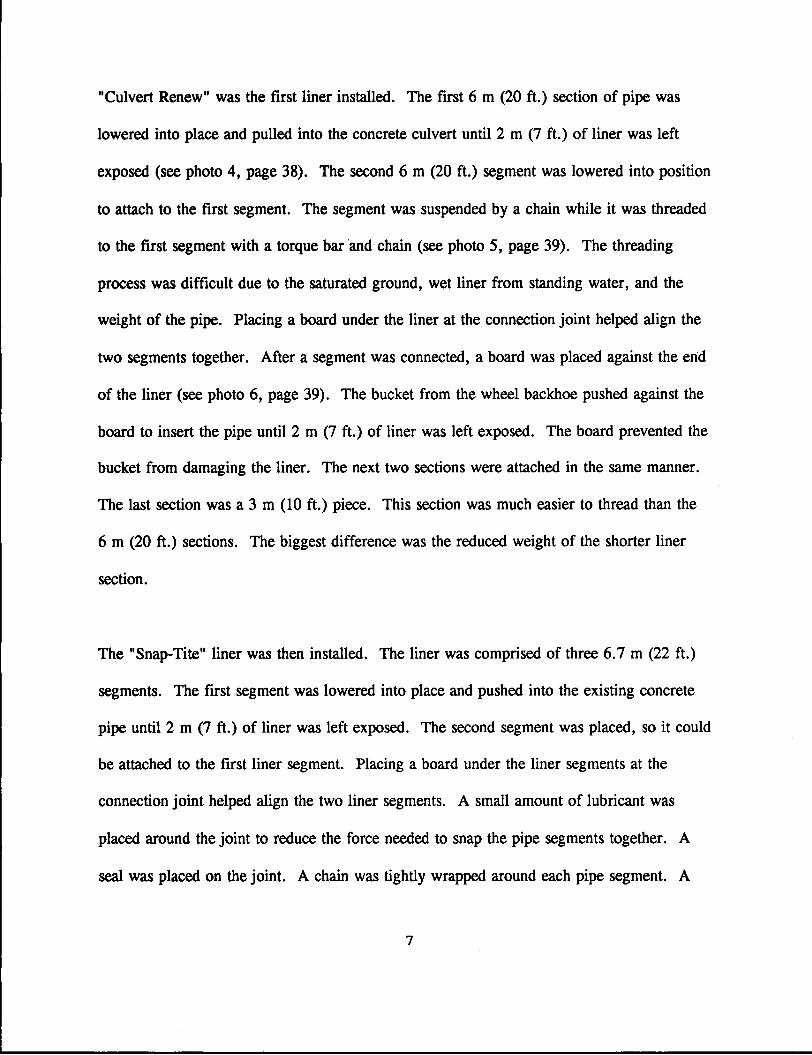
"Culvert Renew" was the first liner installed. The first 6 m (20ft.) section of pipe was
lowered into place and pulled into the concrete culvert until 2 m (7 ft.) of liner was left
exposed (see photo 4, page 38). The second 6 m (20ft.) segment was lowered into position
to attach to the first segment. The segment was suspended by a chain while it was threaded
to the first segment with a torque bar 'and chain (see photo 5, page 39). The threading
process was difficult due to the saturated ground, wet liner from standing water, and the
weight of the pipe. Placing a board under the liner at the connection joint helped align the
two segments together. After a segment was connected, a board was placed against the end
of the liner (see photo 6, page 39). The bucket from the wheel backhoe pushed against the
board to insert the pipe until 2 m (7ft.) of liner was left exposed. The board prevented the
bucket from damaging the liner. The next two sections were attached in the same manner.
The last section was a 3 m (10ft.) piece. This section was much easier to thread than the
6 m (20ft.) sections. The biggest difference was the reduced weight of the shorter liner
section.
The "Snap-Tite" liner was then installed. The liner was comprised of three 6.7 m (22ft.)
segments. The first segment was lowered into place and pushed into the existing concrete
pipe until 2 m (7ft.) of liner was left exposed. The second segment was placed, so it could
be attached to the first liner segment. Placing a board under the liner segments at the
connection joint helped align the two liner segments. A small amount of lubricant was
placed around the joint to reduce the force needed to snap the pipe segments together. A
seal was placed on the joint. A chain was tightly wrapped around each pipe segment. A
7

----------------
pair of winches was used to pull the two pipes together (see photo 7 and 8, page 40). The
process was difficult because the liner segments had slightly deformed into an oval shape.
The crew had to use a pry bar and a screwdriver to help the liners snap together. The liner
segments were inserted until 2 m (7ft.) of the liner remained exposed. The third segment
was attached in a similar process. This time attention was given to align the oval shape of
the pipe segments. The joint went together without any problem from the ovalization of the
pipe segments.
The annular space was filled with flowable mortar the following day. The "Culvert Renew"
liner experienced deformation during the grouting procedure. The hydraulic pressure caused
the liner to deform approximately 100 mm (4 in.) at the braces. The deformation tapered off
for approximately 0.3 m (1 ft.) on each side of the brace. The location'· of one brace was
directly on a liner joint. The joint was stressed and deformed, but it kept the segments
connected. The joint also prevented any water or flowable mortar from leaking into the
pipe. The effect of the deformation will be a reduction in peak flow.
The installation took about ten hours. This included site preparation, lining the culverts,
grouting the pipes and cleaning the work area. The crew required was one equipment
operator (10 hours) and four laborers (three for 6 hours and one for 10 hours). The
equipment used for moving and inserting the culvert liner was a Case 1085 wheel backhoe.
8

Mahaska County
The project is located 1.4 krn (0.9 mi.) west of county road T67 on county road G77 in
Harrison Township (see map, page 30). The existing drainage structure was a 600 mm
(24 in.) diameter CMP with a length of 29.6 m (97ft.). The bottom quarter of the CMP had
rusted away (photo 9, page 41). At approximately 6 m (20ft.) from the south end, the pipe
was bent at a 30 degree angle due to an earth slide on the foreslope.
Installation of the liner occurred on July 27, 1994. The product used for the installation was
a "Culvert Renew" liner. The liner had an ID of 460 mm (18.0 in.), an OD of 510 mm
(20.2 in.), and a length of 29 m (95 ft.). Only 29 m (95 ft.) of liner was ordered since
records indicated the length of the pipe should have been 29.6 m (97 ft.) instead of 29.6 m
(97ft.).
Installation began by unearthing 6 m (20ft.) of the existing pipe on the south end. An
attempt was made to straighten the pipe, so it would be in alignment with the rest of the
culvert. ·BartA was placed below the unearthed CMP segment and compacted. The pipe was
still bent approximately 5 degrees. A small area on the south end of the pipe was cleared to
{)
allow the assembly of the liner. The area was deep enough for the liner to be aligned with
the existing culvert. The first segment of liner was lowered into position and inserted into
the pipe until 1.5 m (5 ft.) of liner was left exposed (see photo 10, page 41). The second
segment was aligned with the first segment. The liner was raised slightly off the ground by
a track backhoe with the use of a chain. A laborer threaded the two segments together using
9

a chain and a steel bar (see photo 11, page 42). The chain is wrapped around the pipe. The
steel bar is placed in the chain and twisted to tighten the chain. The bar is then used as a
leverage device to tum the pipe which threads the liner. The connected segment was pushed
into the CMP by the backhoe unti11.5 m (5 ft.) of liner was left exposed. An old sign was
placed between the liner and the bucket to prevent the bucket from damaging the pipe. The
process was repeated for the rest of the liner.
The pipe was prepared for the filling of the annular space with flowable mortar. The area
above the CMP on the north side of the drainage structure was cleared of earth. A welder
cut a hole approximately 150 mm (6 in.) in diameter in the top of the pipe. The hole was
2 m (7 ft.) from the north end of the pipe. A flowable mortar funnel was made from an
empty steel barrel. The funnel was placed above the hole for the flowable mortar. Earth
was placed around the bucket to hold it in place. The ends of the pipe were sealed with a
heavy cloth material. The cloth material was packed into the annular space at the ends.
Plowable mortar was poured into the annular space. Even though there was a 40% overrun
on the flowable mortar, it did not reach the south end. The standing head in the funnel was
not enough to push any more flowable mortar into the annular space. The extra mortar is
believed to have filled void spaces below the pipe. The pipe liner supplier at the project site
stated that enough annular space had been adequately filled.
The crew required for the installation was one equipment operator (6 hours), two laborers
(5 hours), and one welder (1 hour), for the torch work. The equipment used to move and
insert the pipe was a Link-Belt LS-2800 C-Series II track backhoe.
10

Taylor County
The project site is 3.2 km (2.0 mi.) west of lA 148 on county road J20 (see map, page 31).
The existing drainage structure is a 800 mm (30 in.) diameter CMP with a length of 31.4 m
(103 ft.). The pipe is rusted and deteriorated in the bottom quarter (see photo 12, page 42).
There is approximately 5 m (16ft.) of fill above the CMP.
Preparation for the liner installation occurred on November 2, 1994. An area was cleared on
the south end for the installation of the liner. Holes were cut into the ends of the pipe with a
torch for the flowable mortar. The holes were about 100 mm (4 in.) in diameter and 1.5 m
(5 ft.) from the ends of the CMP.
Installation of the liner took place on November 3, 1994. A "Culvert Renew" liner was
selected for the site. The liner had a 610 mm (24.0 in.) ID, a 690 mm (27.0 in.) OD, and a
length of 33.5 m (110ft.). A pulling cone was made on the first segment to be inserted.
Wedge shapes were cut out of the end of the liner. Holes were drilled in the remaining
wedges. A cable was looped through the holes, so a cone would be formed when the liner
was pulled through the CMP (see photo 13, page 43).
A crane moved the first segment into position. A cable from a dragline attached to a truck
was run through the CMP. The cable was attached to the cone end of the first segment.
The dragline pulled the liner into the pipe until 1.5 m (5 ft.) of liner was left exposed.
During this time, the crane moved the next segment into position. When the dragline was
11
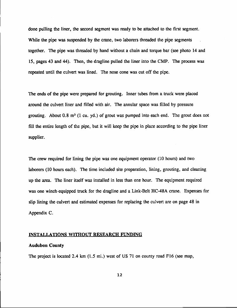
done pulling the liner, the second segment was ready to be attached to the first segment.
While the pipe was suspended by the crane, two laborers threaded the pipe segments
together. The pipe was threaded by hand without a chain and torque bar (see photo 14 and
15, pages 43 and 44). Then, the dragline pulled the liner into the CMP. The process was
repeated until the culvert was lined. The nose cone was cut off the pipe.
The ends of the pipe were prepared for grouting. Inner tubes from a truck were placed
around the culvert liner and filled with air. The annular space was filled by pressure
grouting. About 0.8 m3 (1 cu. yd.) of grout was pumped into each end. The grout does not
fill the entire length of the pipe, but it will keep the pipe in place according to the pipe liner
supplier.
The crew required for lining the pipe was one equipment operator (10 hours) and two
laborers (10 hours each). The time included site preparation, lining, grouting, and cleaning
up the area. The liner itself was installed in less than one hour. The equipment required
was one winch-equipped truck for the dragline and a Link-Belt HC-48A crane. Expenses for
slip lining the culvert and estimated expenses for replacing the culvert are on page 48 in
Appendix C.
INSTALLATIONS WITHOUT RESEARCH FUNDING
Audubon County
The project is located 2.4 km (1.5 mi.) west of US 71 on county road F16 (see map,
12

page 32). The existing structures are two 600 mm (24 in.) diameter concrete pipes with
lengths of 18.3 m (60 ft.). "Snap-Tite" liners with a 480 mm (18.8 in.) ID and 510 mm
(20.0 in.) OD were used. The liners were 18.3 m (60ft.) and 18.9 m (62 ft.) in length.
The liners were installed on May 23, 1994. The longer liner was installed in the east pipe.
The extra 0.6 m (2 ft.) was used to make a bullet nose. The bullet nose was formed by
cutting out wedges in the end of the pipe with a chain saw (see photo 16, page 44). The
remaining wedges on the liner were wired together to form a bullet nose. The liners were
installed with a Gradal. The annular space was filled with a flowable mortar. Small
headwalls were formed and pored on the inlet ends.
Crawford County
The project is 3.1 km (1.9 mi.) east of county road M55 on county road E16 (see map,
page 33). The existing drainage structure was a 1050 mm (42 in.) diameter spiral CMP with
a length of approximately 37 m (120ft.). The pipe extended approximately 18 m (60ft.)
under the road, then it turned down the slope at an angle of about 20 degrees for an
additional 18 m (60ft.). The 18 m (60ft.) section under the road was the only section of
the pipe to be lined. The culvert was lined on May 25, 1994. A "Snap-Tite" liner with a
860 mm (34.0 in.) OD and a length of 20m (66ft.) was used. The extra liner length was to
move the culvert inlet away from the shoulder. A headwall was built at the culvert entrance.
13

----------------------
Henry County, Geode Park
The project is in Geode Park on the west side of the lake between the boat docks and a small
picnic area (see map, page 34). The existing pipe was a 450 mm (18 in.) diameter CMP
with a length of 18 m (60ft.). The bottom quarter of the pipe was rusted out.
Installation of the liner occurred on September 8, 1994. The product used for this
installation was a 410 mm (16.0 in.) OD "Snap-Tite" liner with a length of 19.8 m (65 ft.).
The liner was gravity grouted with flowable mortar from the inlet end. Installation required
two laborers and an equipment operator for 5 hours each. A John Deere backhoe was used
to install the pipe liner.
Jones County
The project is north of Anamosa on county road X31 (see map, page 29). The culvert was a
900 mm (36 in.) diameter CMP with a length of 18.3 m (60ft.). The liner was a 810 mm
(32.0 in.) OD "Snap-Tite" liner with a length of 19.2 m (63 ft.). The liner was installed on
September 12, 1994.
Mahaska County
The project site is located 7.5 mi. west of lA 137 on county road G71 in Section 23 of
Jefferson Township (see map, page 30). The existing drainage structure is a 600 mm (24
in.) diameter CMP with a length of 27 m (90ft.). The bottom quarter of the pipe was
corroded. The liner used for the project was a "Culvert Renew" liner with a 460 mm
14

--- ------ ----·-----
(18.0 in.) ID, 510 mm (20.2 in.) OD, and a length of 29 m (95 ft.). Installation of the liner
occurred on November 27, 1994. On November 28, 1994 the annular space was filled with
flowable mortar. The mortar was placed through a hole in the top of the CMP at the inlet
end. The mortar did not fill the entire length of the pipe.
Pottawattamie County
The project is on county road M47 0.1 km (0.06 mi.) north of lA 6 (see map, page 35).
The existing culvert was a 1800 mm (72 in.) diameter CMP with a length of 18.3 m (60ft.).
The bottom of the culvert was corroded. A "Snap-Tite" liner with a 1290 mm (50.7 in.) ID,
1370 mm (54.0 in.) OD, and a length of 18.3 m (60 ft.) was used. The liner was installed
on May 24, 1994.
GENERAL INSTALLATION PROCEDURE
Clean the Existine Culvert
The liner is easier to push or pull through a clean culvert. A clean culvert is important for
grouting the pipe in place. The culvert most commonly has been flushed clean with water.
The culvert is generally flushed clean several days before the lining operation. This will
allow the work site time to dry from the flushing operation.
Prepare the Work Area
The work area is preferably dry. The operation is generally easier and faster in a dry work
area. If water is flowing through the work area and the existing drainage structure, a dam
may be desirable to temporarily stop the flow of water.
15
------------------,
The work area should be cleared to allow easy assembly of the pipe. This may include the
removal of fence and the excavation of soil. The pipe is easier to slip line if the pipe liner
can be inserted at the same angle as the drainage structure. The work area should be long
enough to allow a pipe segment to be attached to the liner already in the pipe. Generally,
this minimal distance is the length of the longest segment of the liner plus 1.5 m (5 ft.).
Prepare Access Points for Groutine
If the desire is to grout the pipe at locations other than at the ends of the pipe, access holes
will need to be cut into the existing culvert. When deciding on the location of the access
points, consideration should be given as to how the mortar or flowable grout will be
transported to the points of grouting. It is usually preferable to create the access points
before lining the drainage structure.
Insertine a Cable Throuw the Culvert
If the liner is to be pulled through a culvert, a cable will need to be placed through the
culvert. Care should be taken to make sure that the safety of workers will not be
compromised while placing a cable through the culvert. Remember, the liner can be pushed
through the drainage structure if no safe method can be found to place a cable through the
culvert.
16

------- --- ----------
Pullin& Head or Nose Cone
Decide if a nose cone or pulling head will be required. If the existing structure is misaligned
or badly deteriorated, a nose cone or pulling head is very desirable. A liner without a nose
cone or pulling head will easily catch a very small obstruction. If the existing culvert has
misaligned joints or is bent, a nose cone or pulling head is recommended.
A nose cone or pulling head can be easily constructed from the liner itself. Wedges can be
cut out of the front part of the first segment of the liner. Holes are drilled through the
remaining wedges. The wedges are then tied together with wire or a cable to form a cone.
After lining the culvert, the nose cone is cut off. If several culverts are to be lined with the
same diameter of liner, a short segment of liner may be purchased to make a detachable nose
cone or pulling head. The segment would be made as described above, but after lining the
segment would be detached and used again.
Assemblina= the Culvert
Check to see if any of the segments have plain ends. If some of the sections do have plain
ends, these sections will be the first and last segments used. If a reusable nose cone is to be
utilized, make sure that the first segment was machined for a joint assembly.
The pipe may be completely assembled prior to installation, however, the lack of space will
often make this procedure impossible. The other alternative is to assemble and insert the
liner segment by segment. If it is required to assemble the liner segment by segment, the
following tips will be helpful.
17

~-------------------
1. Don't insert each segment completely into the existing drainage structure. Leave enough of the liner exposed to attach the next liner segment.
2. A board placed under the two segments of liner being joined may help as a guide in aligning the segments.
3. Pushing the culvert in may be accomplished by attaching a choker chain around the pipe and pulling the chain with a backhoe arm. Also, insertion of the liner may be accomplished by pushing the pipe in with the bucket of a backhoe or other similar piece of construction equipment. Because the bucket might damage the joint of the pipe, a plate or board will need to be placed between the pipe and the bucket.
Groutine
The pipe should be grouted according to manufactures specifications. The pipe may be
forced upward during grouting. If flow lines are critical at the location, the pipe may need
to be braced, or the pipe may need to be grouted in several lifts. More detailed
consideration about grouting is given later.
Headwalls
Headwalls may be built at the culvert inlet and outlet. Headwalls can be very beneficial to
the lined culvert. The headwalls can anchor the pipe liner, reduce erosion, provide fire
protection, and improve water flow.
CONSIDERATIONS FOR GROUTING
The method of grouting is very important to polyethylene liner installations. If the liner is to
be estimated at having a long service life, it must be able to withstand the possibility of the
original drainage structure loosing its capacity to support soil and traffic loads. The liner
would then be required to support the overburden and traffic loads. The polyethylene liners
18

have shown that they are susceptible to deformation from large point loads during grouting
procedures. A slip lined culvert that is grouted the full length would be able to distribute the
overburden and traffic loads if the existing culvert experienced· structural failure. A lined
culvert that is only grouted at the ends would remain susceptible to dramatic failures when
the original drainage structure fails. The culvert lined at the ends would also allow material
to fall into the annular space between the culverts as the original drainage structure corroded.
This process could lead to the settlement of the roadway or a collapse of the roadway as
material is lost into the annular space. An alternative to grouting the annular space the full
length is to use a flowable mortar or flowable fill (Controlled Low-Strength Material) to fill
the annular space. This gives the polyethylene liner a good backfill to distribute loads, and it
prevents the loss of material into the annular space.
The type of grouting practice to be used may depend on the purpose of the slip lining and the
condition of the drainage structure. If the lining is to restore flow until reconstruction can
occur in a few years or even twenty years, the grouting technique will not be as critical as
long as the culvert is in good structural condition. However, if the slip lining procedure is
for a long term (50 to 100 year design life), stronger consideration should be given to
grouting the annular space full length.
Grouting for most of the installations to date has been with a flowable mortar. The mortar
has usually been placed by gravity through a hole in the top of the old drainage structure
near the ends of the culvert. This method does not always allow the annular space to be
19

completely filled. More of the annular space may be filled by using some of the following
methods:
1. The use of grout stand pipes when pouring the grout into the annular space. The grout stand pipes would increase the head on the grout being placed in the annular space.
2. The addition of more grout access points. Holes could be made near the shoulder or possibly drilled at the centerline to ensure that more of the culvert is properly grouted.
3. Use pressurized grouting procedures. This will allow the grout to be placed further into the annular space.
4. Use a long grout pipe starting at the far end. Then slowly withdraw the pipe as the annular space fills up.
5. Use the liner as a grout tube. Drill holes in the top of the liner. Use the holes to fill the annular space with grout.
6. Provide air outlet points or pipes so that no large air voids are trapped in the annular space.
More work needs to be done on grouting practices and on appropriate grout and flowable
mortar mix designs. Page 52 in Appendix E has a grout design used by the Indiana
Department of Transportation.
BRACING
Bracing procedures were very important on several of the installations. Problems developed
when the existing culvert and the liner had a large enough difference in diameter that the
liner needed to be braced to maintain the flow line. Also, the bracing became more
important as the diameter of the liner increased. Neither pipe supplier provided a bracing
guideline; therefore, the responsibility of proper bracing was left to the engineer. . This is an
area that needs to be addressed in the future.
20

The pressures exerted on a liner are especially large when the entire annular space is
grouted. These pressures can cause the pipe to experience excessive deflection or failure if
the bracing is not adequate. Currently, the engineer will be required to develop an effective
bracing system. The engineer can also use some of the following suggestions to help reduce
the hydraulic pressures.
1. The annular space can be grouted or filled with a flowable mortar in several lifts.
2. Build headwalls at the ends of the culvert to weigh down and secure the culvert liner before grouting.
3. Use low density grouts to reduce hydraulic stresses.
4. Monitor the pressure applied if pressure grouting is used to fill the annular space.
FLOW CAPACITY
An advantage of smooth interior wall polyethylene liners is the low Manning roughness
coefficient of about 0.010. This coefficient is lower than both concrete pipe and corrugated
metal pipe. The lower Manning coefficient means that a smaller diameter liner may have a
flow equal to or greater than the original pipe. If pipe flow is simplified to consider only
Mannings equation, a simple derivation can be performed to calculate the needed diameter
for a liner to have the same flow as the original drainage structure. The derivation is on
page 50, in Appendix D.
The reduced cross section may not reduce the flow, but it will increase the velocity of the
water in the pipe. This increase in velocity might create a need for a special end treatment
to prevent erosion.
21

EVALUATION
The Iowa Department of Transportation and Dallas, Jefferson, Jones, Mahaska, and Taylor
Counties will jointly conduct evaluations each year through 1999 on the research funded
installations. The other installations will be evaluated each year by Iowa Department of
Transportation personnel. The following table shows the evaluation plan for the research
funded installations.
CONSTRUCTION YEAR YEAR YEAR YEAR YEAR TEST YEAR 1 2 3 4 5
ORIGINAL LINER PIPE
Visual Examination X X X X X X X
Video X X Camera X
CRITERIA FOR USING POLYETHYLENE
Acid Conditions
Locations where extensive mining has occurred can cause acid runoff which can corrode
metal pipes. Polyethylene pipe is highly resistant to acids, and it may be a good alternative
in other acidic conditions.
Deep Fill Sections and Hieh Traffic
Liner for locations that have deep fills or have high traffic can usually be justified
economically. Replacing a pipe under a deep fill can be cost prohibitive. The cost to users
22

------------------------
of a roadway can be high when large volumes of traffic need to be detoured for the
replacement of a drainage structure. Slip lining a drainage structure with these conditions
becomes econmically attractive.
Cost of Slip Linin&
Even when deep fills or high traffic volumes are not encountered, the cost of lining a
drainage structure can be comparable to removing and replacing a drainage structure when
all the costs associated with the project are calculated. These costs will include the cost of
the pipe, excavation, backfill, repaving the road, labor, equipment, grouting, and detouring
the traffic. Plus, there still exists the risk involved in having the road cut open, and the
possibility of the roadway settling because of inadequate backfilling. Polyethylene liners are
easily installed with the equipment that most county, highway or city maintenance
departments have. The work crew and time required for the installation are minimal.
Public Relations
The traveling public is quick to complain about any restrictions or repairs on a roadway.
Slip lining with a polyethylene liner allows a crew to repair a deteriorated drainage structure
without disrupting traffic or intruding on the public.
Pipe Alienment
The pipe must be relatively straight to be lined with a polyethylene liner. The liner can go
around small deflections, but large angle elbows will be difficult to pass with a liner. The
23
pipe liner supplier should be consulted before an attempt at lining a misaligned, curved, or
bent culvert is made.
DISCUSSION
Culvert slip lining with polyethylene liners can be a viable alternative to the removal and
replacement of deteriorated drainage structures. The polyethylene liners can be easily
installed with little time and equipment commitments by most highway, county, and city
maintenance departments. The liners appear to be capable of being both a short term and a
long term maintenance procedure. If the liner requires bracing, careful consideration should
be given to the bracing design. The grouting procedure should be appropriate for the desired
life of the lined culvert. The cost comparisons show that the slip lining technique can be
competitive with the removal and replacement of an existing drainage structure. Culvert slip
lining is most competitive economically when the roadway is paved, the culvert is under a
deep fill, or traffic volumes are high.
The Iowa Department of Transportation does not have a specification for lining culverts with
a polyethylene liner. At this time, the only approved uses for polyethylene pipe are for
unclassified roadway pipe culverts and unclassified entrance pipe culverts. The
Specifications Committee has approved both "Snap-Tite" and "Culvert Renew" for lining
culverts when specified (see letters in Appendix F, pages 54 and 55).
24

ACKNOWLEDGEMENTS
Research project HR-370 was sponsored by the Iowa Highway Research Board and the Iowa
Department of Transportation. Partial funding for this project was from the Secondary Road
Research Fund in the amount of $10,000.
The authors would like to thank the employees of Audubon, Crawford, Dallas, Jefferson,
Jones, Mahaska, Pottawattamie, and Taylor Counties for their effort in installing the
polyethylene liners. Thanks to the employees of the Iowa Department of Transportation who
installed the liner in Geode Park. Thanks is extended to Vernon Marks and Kathy Davis for
their help in the production of this report. Thanks is also given to Bob Steffes for assisting
with the video camera work in evaluating the project sites.
REFERENCES
1. California State University; Culvert Restoration Technigues; California Department of Transportation and Federal Highway Administration; FHWA/CA/TL #93-14; Caltran Study# F90TL15; 1993. .
2. Minnesota Department of Transportation; Culvert Renewal; Minnesota Department of Transportation MN/RD-92-02; April 1992.
3. McCullouch, B. G.; Repair and Rehabilitation of Deteriorated Drainage Pipe; Indiana Department of Transportation and Federal Highway Administration; FHW A/IN/JHRP 91/14; October 1991.
4. Thomas, Richard; Indiana Department of Transportation; Presentation at Indiana Department of Transportation Annual Engineers Meeting 1990 titled "Polyethylene Liner Pipe."
5. Boles, Richard and Campbell, Steve; Liners Give Rusted Culverts New Life. Higher Capacity; Roads and Bridges; February 1994.
6. Adaska, Wayne; Controlled Low-Strength Material Turns Old Bridges to Roadways; Roads and Bridges; February 1995.
25

DALLAS COUNTY
760 nun (30 in.) ID "CULVERT RENEW" LINER IN A 900 nun (36 in.) CMP

JEFFERSON COUNTY
760 mm (30 in.) ID "SNAP-TITE" LINER IN A WOOD BOX CULVERT;._.· -..a.

JONES COUNTY

MAHASKA COUNTY
~ 460 mm (18 in.) ID "CULVERT RENEW' LINER · IN A 600 mm (24 in.) CMP ~~~
460 mm (18 in.) ID "CULVERT RENEW'' LINER IN A 600 mm (24 in.) CMP

TAYLOR COUNTY
6
610 mm (24 in.) ID "CULVERT RENEW" LINER IN A 800 mm (30 in.) CMP
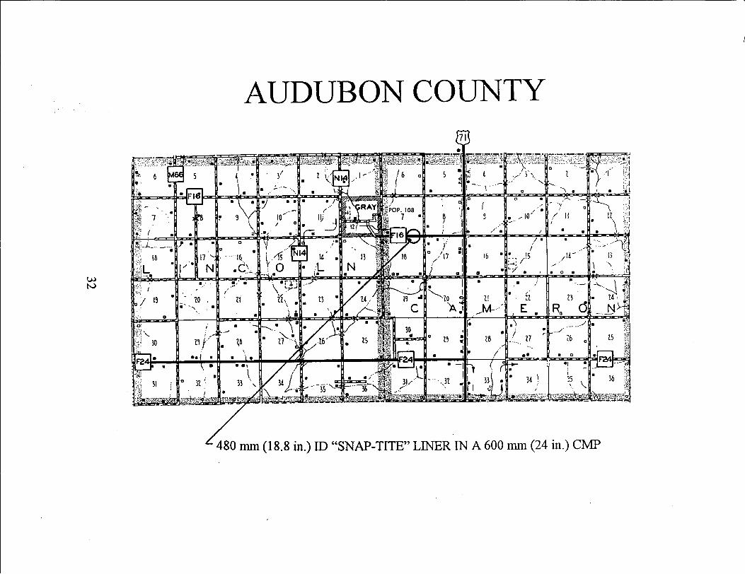
AUDUBON COUNTY
34 \
480 nun (18.8 in.) ID "SNAP-TITE" LINER IN A 600 mm (24 in.) CMP

.-------------------------------
CRAWFORD COUNTY
• • •
16 • 17 •
• • •
810 mm (31.9 in.) ID "SNAP-TITE" LINER IN A 1050 mm (42 in.) CMP
33

• 31
HENRY COUNTY GEODE PARK
34
380 mm 05 in.) ID "SNAP-TITE" LINER IN A 460 mm (18 in.) CMP

POTTA WATTAMIE COUNTY
I& I l7 I• L/
a J D
to
1 I D
• •
35
1290 mm (50.7 in.) ID "SNAP-TITE" LINER IN A 1800 mm (72 in.) CMP

Photo 1 Wood Box Culvert in Jefferson County
37
Photo 2 Connecting "Snap-Tite" Liner Segments Jefferson County

Photo 3 Twin Concrete Culverts in Jones County
Photo 4 First Segment of "Culvert Renew" Being Pulled Into the Concrete Culvert (Jones County)
38

Photo 5 Threading "Culvert Renew" Liner Segments in Jones County
Photo 6 Use of a Board to Protect the Culvert Liner While it is Pushed
into the Concrete Culvert (Jones County)
39

Photo 7 Connecting "Snap-Tite" Liner Segments (Jones County)
Photo 8 Connecting "Snap-Tite" Liner Segments (Jones County)
40

Photo 10 Approximately 1.5 m (5 ft.) of liner is Left Exposed to Attach the Next Segment (Mahaska County)
41
Photo 9 Bottom of CMP Has Rusted Away (Mahaska County)
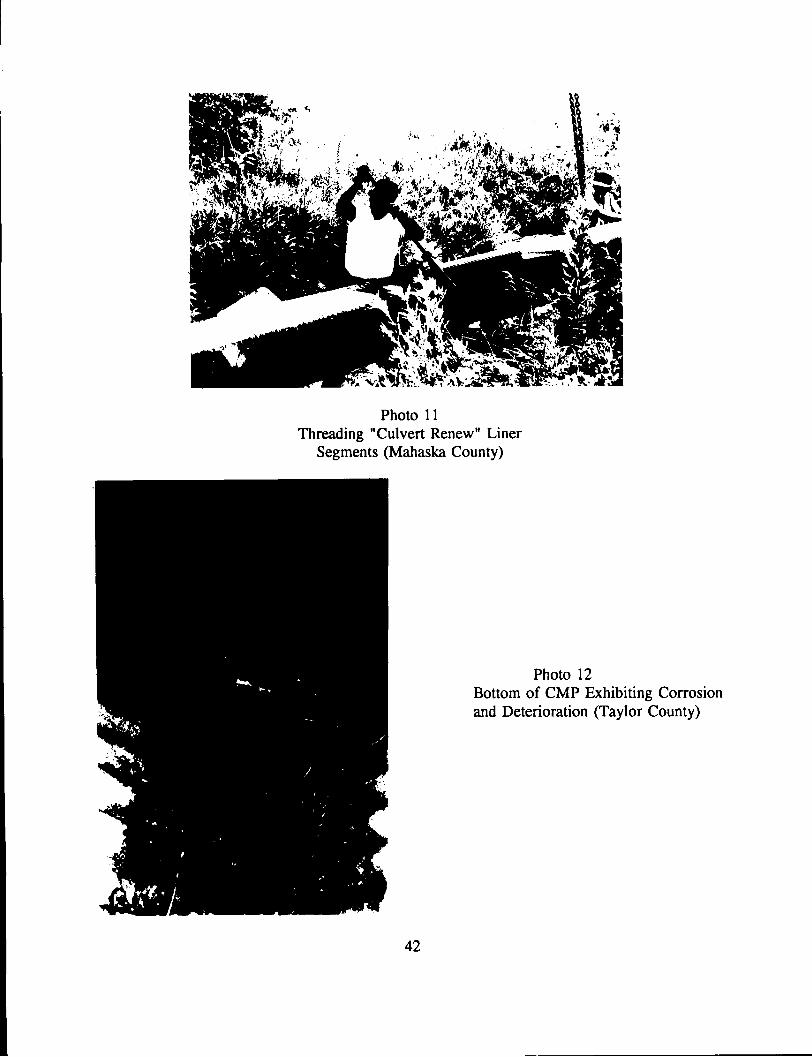
Photo 11 Threading "Culvert Renew" Liner
Segments (Mahaska County)
42
Photo 12 Bottom of CMP Exhibiting Corrosion and Deterioration (Taylor County)

~
~ • ~ . ~
I. ~ ~ :. •
Photo 13 Nose Cone (Taylor County)
Photo 14 Threading "Culvert Renew" Liner Segment by Hand
(Taylor County)
43
<II

Photo 15 Work Area for Assembling Liner
(Taylor County)
Photo 16 Cutting of Nose Cone With Chain Saw
(Audubon County)
44

DALLAS COUNTY COST COMPARISONS
SLIP LINING ACTUAL EXPENSES
30 " ID POLYETHYLENE LINER PRESSURE GROUTING AND MORTAR LABOR EQUIPMENT
TOTAL
$4,058.28 $1,214.72 $ 532.19 $ 225.00
$6,030.19
Note: The culvert liner was purchased at a reduced price for this research. The actual culvert price for the product was approximately 3 5% greater than the price listed in this summary of expenses.
ESTIMATED COST OF REPLACEMENT
30" CONCRETE ROADWAY PIPE ($39.22/LF* FOR 105 LF) $4,118.10 EXCAVATION, CLASS 20 ($5.30/CY* FOR 200 CY) $1,060.00 BACKFILL AND COMPACTION ($6.39/CY* FOR 200 CY) $1,278.00 PAVING OF PCC SURFACE, STANDARD P.C. CONCRETE
CLASS C, 7 IN. ($44.70/SY* FOR 73 SY) $3,263.10 DETOURING TRAFFIC AND CLOSING ROADWAY# $1,000.00
TOTAL $10,719.20
* Costs for the replacement of the culvert are estimated from the average unit costs listed in the Summary of Awarded Contract Prices 1994 for the Iowa DOT.
# Engineers Estimate
46

JEFFERSON COUNTY COST COMPARISONS
SLIP LINING ACTUAL EXPENSES
30" ID POLYETHYLENE LINER FLOWABLEMORTAR (11.5 CUBIC YARDS) LABOR EQUIPMENT
TOTAL
$3,500.00 $ 431.25 $ 253.70 $ 110.80
$4,295.75
Note: The polyethylene liner was purchased at a reduced price for this research. The actual retail price for the product would have been greater than the price listed in this summary of expenses.
ESTIMATED COST OF REPLACEMENT
36" CONCRETE ROADWAY PIPE ($45.58/LF* FOR 60 LF) EXCAVATION, CLASS 20 ($5.30/CY* FOR 75 CY) BACKFILL AND COMPACT ($6.39/CY* FOR 75 CY) REPLACING GRANULAR SURF ACING ON ROADWAY,
CLASS B GRAVEL ($7.63/TON* FOR 16 TONS) DETOURING TRAFFIC AND CLOSING ROADWAY#
TOTAL
$2,734.80 $ 318.00 $ 479.25
$ 122.08 $ 500.00
$4,154.13
*Cost for the replacement of the culvert are estimated from the average unit costs listed in the Summary of Awarded Contract Prices 1994 for the Iowa DOT.
47

TAYLOR COUNTY COST COMPARISONS
SLIP LINING ACTUAL EXPENSES
24" ID POLYETHYLENE LINER PRESSURE GROUTING MORTAR (3 CUBIC YARDS) LABOR EQUIPMENT
TOTAL
$3,768.10 $1,444.17 $ 210.00 $ 622.53 $ 319.20
$6,364.00
Note: The polyethylene liner was purchased at a reduced price for this research. The actual retail price for the product was approximately 35% greater than the price listed in the summary of expenses.
ESTIMATED COST OF REPLACEMENT
30" CONCRETE ROADWAY PIPE ($39.22/LF* FOR 105 LF) $4,118.10 EXCAVATION, CLASS 20 ($5.30/CY* FOR 1050 CY) $5,565.00 BACKFILL AND COMPACT ($6.39/CY* FOR 1050 CY) $6,709.50 PAVING OF PCC SURFACE, STANDARD P.C. CONCRETE
CLASS C, 7 IN. ($44.70/SY* FOR 147 SY) $6,570.90 DETOURING TRAFFIC AND CLOSING ROADWAY# $1,000.00
TOTAL $23,963.50
* Costs for the replacement of the culvert are estimated from the average unit costs listed in the Summary of Awarded Contract Prices 1994 for the Iowa DOT.
# Engineers Estimate
48
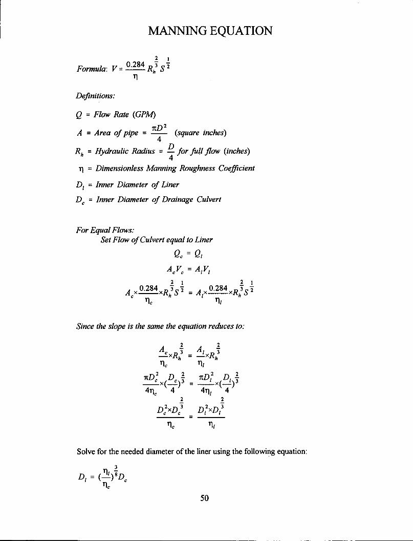
MANNING EQUATION
2 1
Formula: V = 0·284 Rh3 S 2 ,
Definitions:
Q =Flow Rate (GPM)
. rtD 2 A = Area of p1pe = -- (square inches)
4
Rh = Hydraulic Radius = D for full flow (inches) 4 -
11 = Dimensionless Manning Roughness Coefficient
D1 = Inner Diameter of Liner
D c = Inner Diameter of Drainage Culvert
For Equal Flows: Set Flow of Culvert equal to Liner
Qc = Ql
ACVC =AlVl
2 1 2 1
A 0.284 R3S2 _A 0.284 R3S2 X----X h - IX----X h
c 'lc '11
Since the slope is the same the equation reduces to:
---=
Solve for the needed diameter of the liner using the following equation:
50

GROUT DESIGN PRESENTED AT 1990 INDIANA ANNUAL ENGINEERS :MEETING
by Richard Thomas District, Maintenance Field Engineer
300 lb. cement (type 1) 1500 lb. fly ash (type Cor F) 156 oz super plasticizer (Rheobuild 1 000) As needed air entraining admixture to obtain 10% air content 45 gal. water 1200 lb. fine aggregate (SSD)
The Indiana Vincennes District Maintenance used this mix to gravity grout liner with the use of PVC stand pipes. The mix was vibrated with a portable vibrator to help the mix flow.
52

r
800. Lincoln Way, Ames, Io~a 50010 515/239-1447
october 22, 1992
·Mr. Bruce Larson STS Systems, Inc. P.O. Box 328 Chesterfield, Missouri 63006
Dear Mr. Larson:
Ref. No.: 435.34D
Thank you for your interest in supplying products for Iowa DOT use. Your Snap-Tite polyethylene pipe has been reviewed by the New Products Subcommittee and tested by the Materials Laboratory. The Specifications Committee has approved your Snap-Tite p:pe for use when specified in the plans.
VJM:kmd cc: J. Hocker
54
Sincerely,
Vernon J. Marks Research Engineer Materials - Research

r 800 Lincoln Way, Ames, Iowa 50010 515/239-1447
January 28, 1994 Ref. No.: 435.340
steve campbell Poly systems Incorporated P.O. Box 1157 steelville, Missouri 65565
Dear Mr. Campbell:
Thank you for your interest in supplying Culvert Renew for Iowa DOT use. Culvert Renew has been reviewed by our New Products Evaluation Subcommittee. Upon their recommendation, the Specifications Committee has the culvert liner and coupler for Iowa DOT use. Specifications Committee also suggested that the
approved The Office of