pipe machine model no. 7991 - carid.compipe machine model no. 7991 wheeler-rex operation manual be...
TRANSCRIPT
PIPE MACHINE
Model No. 7991 Wheeler-REX
OPERATION MANUAL
Be sure to read this Operation Manual before using the machine
- Note -
· Be sure to hand this operation manual to the user. · To ensure safe and efficient use of this machine, read this
operation manual very carefully before use.
· Be sure to keep this operation manual where the operator can
refer to it whenever necessary.
• Be sure to observe the Safety Precautions described below to prevent accidents such as fire, electric
shock and injury.
• Read these Safety Precautions carefully before using the machine, and operate the machine according
to the instructions.
• Do not use the machine in any way other than as described in this operation manual.
Definitions of
CONTENTS Safety Precautions • • • • • • • • • • • • • • • • • • 1 Instructions for using the No.7991 • • • • • • • 3 Names of Parts, Standard Specifications, Standard Accessories 6 Operating Instructions
1. Transporting the Machine
2. Positioning the Machine • • 3. Oil · • • • · · • · · · · · 4. Attaching and Removing the Die Head • 5. Operating the Die Head
6. Inserting and Removing Pipes
7. Power Supply • • • • • • • • 8. Pre-Operational Inspection • • • • • • 9. Motor (with brake) • • • • • • • • • • 10. Cutting Pipes
11. Chamfering • •
. . . . . 7 . 7 · 7 · 7
. . . . 8 10 10 . . . . . 11
. . . . . . . . 11 12
. . . . . . . . 13 12. Carriage Protection Mechanism • • • • • • • • 13
14 15 16
13. Cutting Threads • • • • • • • • • • • • Daily inspection, maintenance • • • • • • • • • • • • • • Repairs • • • • • • • • • • • Before requesting repairs or servicing
A WARNING and A CAUTION
17
A WARNING In this operation manual, warnings are divided into and A CAUTION
A WARNING : indicates actions which could possibly result in death or severe injury to the userif the machine is used incorrectly.
A CAUTION : indicates actions which could possibly result in injury to the user, or physical damage, if the machine is used incorrectly. Even items described as [ L:G, CAUTION], could have serious results under certain conditions.Be sure to observe these warnings carefully as they greatly affect safety. · If this operation manual is lost or damaged, promptly order a replacement from our agent or sales agent. · Parts and specifications are subject to change without prior notice, due to improvements in quality, performance or safety standards. In such cases, the contents, photographs, illustrations, etc. of this manual may be different to the product you have purchased.
Safety Precautions
A WARNING 1) Ensure you use the correct voltage.
• Be sure to use the voltage indicated on the name plate of the main unit or in the operation manual. If the voltage is different from the voltage indicated overheating, smoke or fire may occur.
2) Check the switch is OFF, before inserting the plug into the power supply socket.• If the plug is inserted into the power supply when the switch is ON, the machine may start operation abruptly, and is
liable to cause accidents. Be sure to check the switch is OFF.
3) Be sure to avoid electric shock.• Do not touch the plug with wet hands.• Do not use the machine in rain or in places where water can easily get into the machine. • Be sure to ground the machine to avoid electric shock.
4) Take notice of conditions at the work site.• Do not use the machine in rain, humid or damp places, or places where water can easily get into the machine.
Humidity will lower insulation of the motor and cause electric shock. • Do not use close to flammable fluids or gases, such as gasoline and paint thinner. Fire or explosion might occur.
5) Use designated accessories and attachments.• Do not use accessories and attachments other than those designated in the operation manual or our catalogs. Accidents
or injuries might result.
6) In the following cases, tum the main unit OFF and pull the plug out of the power supply socket.• When the machine is not in use or parts are changed, repaired, cleaned or inspected. • When accessories are changed. • When hazards are expected (including electric power failure).
When the plug is inserted, the main unit may start operation unexpectedly, causing accidents.
7) If any abnormality is noticed, stop operation immediately.• When operation of the machine is not smooth or abnormalities such as unusual smells, vibration or noise are detected,
immediately stop operation of the machine. • Check symptoms against the items in [Troubleshooting Methods] in the operation manual, observe corresponding
instructions. If the machine is used continuously, overheating, smoke or fire might occur, causing accidents or injuriy. • If overheating or smoke from the main unit occurs, do not attempt an overhaul but ask for an inspection and repair.
8) Keep the work site clean.• Ensure you keep the work table and the work site in good order, and well lit.
A cluttered site and work table are liable to cause accidents.
9) Do not let unauthorised personnel come near the machine.• Do not let any people other than authorised personnel touch the main unit or the power supply cord or operate the
machine. • Do not let people other than authorised personnel enter the work site, especially children.
Injuries might occur.
10) Do not use the machine with force.• Use the machine only for its designated purpose. Operate according to the capacity of the main unit, to assure safe and
effective operation. Forced operation may not only cause damage to the product but also accidents. • Do not use the machine in any way that could cause the motor to lock, or cause smoke or fire.
11) Wear appropriate clothing.• Do not wear neck ties, clothes with open sleeves, loose clothing, accessories such as necklaces, etc., which could get
caught in the rotating parts. When working outdoors, it is recommended to wear rubber gloves and shoes with stoppers. Slippery gloves and shoes are liable to cause injuries.
• Cover long hair with caps or hair nets, to prevent them getting caught in rotating parts. • Wear safety caps, safety shoes, etc. according to the working environment.
- 1 -
Safety Precautions
A WARNING 12) Do not work in an unnatural posture.
• Keep a firm footing and balance to avoid falling over and injuring yourself.
13) Remove tools such as wrenches.• Before turning ON the switch, check that tools used for inspection and adjustment have been removed.
If you use the machine when tools are left inside it, accidents and injuries may occur.
14) Operate the unit with great care.• Always work with great attention to handling methods, working methods and surrounding conditions. Carelessness
may result in accidents and injuries. • Do not operate the machine when your concentration is lowered such as when tired, after drinking alcohol, when sick,
affected by medicines, etc.
15) Handle the power supply cord with care.• Do not carry the product by the cord, or pull the plug out of the socket with the cord. • Do not place the cord near heated objects, fats & oils, cutters and other objects with sharp edges. • Take care not to step on the cord, pull the cord or apply unnecessary force resulting in damage to the cord.
Electric shock or short-circuit may occur, causing fire.
16) Perform careful maintenance daily.• When changing accessories and parts, follow the operation manual. • Periodically inspect the power supply cord and plug. If damaged, ask your sales agent or our sales branch for repairs.
If an extension cord is used, inspect the cord periodically, and if damaged, replace it.• If extension cords are used outdoors, use cords designed for outdoor use to prevent electric shock, short-circuit or fire. • Keep grips dry and clean and free of oil and grease. Slipping may cause injury.
17) Check for damaged parts.• Before using the machine, carefully check for damage to the protective cover and other parts, and check both normal
operation and specified functions. • Check for any abnormalities such as in adjustment of movable parts, tightening, damage to parts, and all parts affecting
operation. • Do not use machines if the stop and start switches do not work. • In replacing or repairing a broken protective cover and other parts, follow the operation manual.
If no instructions are specified in the operation manual, ask your sales agent or our sales branch for repairs.
18) Store carefully when the machine is not in use.• Store in a dry place away from children and locked with a key.
19) For overhaul and repair of the machine, ask an appointed Wheeler-Rex agent.• Our products comply with corresponding safety standards. Do not remodel. • Be sure to ask your sales agent or our sales branch for any repairs.
If repairs are carried out by unskilled or unqualified personnel, the performance of the unit will be adversely affected and may result in accident or injury.
- 2 -

Instructions for using the No.7991
• Threading workA WARNING
CD Take care when handling blades and other sharp objects.·To prevent accidents and injury, take special care when handling blades and other sharp objects such as the dies,
reamer, pipe cutter and carbide cutter, etc.
@ Do not place your hands or face close to rotating parts while the machine is operating. · Inserting your hands into rotating parts and dies will result in accidents and injury.
®Do not perform the next operation until the machine has stopped rotating completely. · · Rotation does not come to a complete standstill when you tum the switch OFF. Before starting the next job, check that rotating parts have stopped. Failure to do so may result in accidents and injury.
@ Do not leave the machine while it is still rotating·Others may be injured.
® If the mac!J.ine is accidentally dropped or hit, check carefully for damage such as cracks, broken parts, ordeformation.
· If any abnormalities are detected, ask your sales agent or our sales office for inspection and repair. Continuing to usethe machine in such a state may result in malfunction, accidents or injury.
® Do not touch the dies just after threading· The dies will be very hot just after completing threading. To avoid bums and other injuries, avoid touching them until
they have cooled down.
(j) Die head and dies.· Use the die head and dies that correspond to the diameter of the pipe to be threaded. · Attach the die head correctly to the Carriage. ·Before starting threading, set the die head to the threading position, tum the switch ON, and make sure the threading oil
flows correctly from the die head and that the oil flows onto the dies. Also, make sure there is sufficient oil in the tank to cover the strainer completely. This will prevent not only incorrect threading of the pipe, but also malfunction of the machine, accidents and injury.
® Make sure you start threading from the correct position.
®Use a pipe support when threading long pipes. · When threading long pipes, use the pipe support to prevent vibration from warping while the pipe is rotating. The
support will also prevent the machine from becoming unstable under the weight of the material. · Failure to use the pipe support may not only result in imperfect threads and malfunction of the machine, but may even
lead to accidents and injury.
® Be sure to attach accessories according to the Operation Manual.·If accessories and attachments are not fitted correctly, such parts may drop off during operation or the unit may fall
over resulting in accident and injury.
- 3 -
Instructions for using the No. 7991 • Chamfering work
A WARNING CD To prevent injury, do not touch the reamer blade direcly with your hands as it is extremely sharp.
• Threading OilA CAUTION
CD Wear goggles· Touching the eyes with oil may cause inflammation.
Emergency treatment: Wash eyes with clean water for about 15 minutes and seek medical attention.
@ Take care not to breathe in oil mist or steam.·Breathing in oil mist or steam may cause nausea.
Emergency treatment : Carry the person out into the fresh air, cover them with a blanket, keep them warm and relaxed, and seek medical attention.
® Do not thin the oil or mix it with threading oil produced by other companies.
@ If the threading oil gets contaminated with water during the threading operation and the oil changes to amilky white, .o� the qll;ality of the oil deteriorates significantly resulting m a poor finish to the thiead, replace the 01l 1mmechately.
® Do not drink the oil· Drinking the oil may cause diarrhea or vomiting
Emergency treatment: Do not let the person vomit forcibly; seek medical attention immediately.
® Do not place the oil where it is easily reached by small children.
(j) Be particularly careful about the risk of fire. Depending on the country of use, the oil may be classified asa hazardous material. To prevent fire or explosions, always familiarize yourself with and comply with local laws and regulations pertaining to the handling of such materials.
® Storage· Always close the lid after use to prevent the oil from being contaminated by dust, water or other foreign bodies. ·Store in a dark place away from direct sunlight.
® Handling waste oil and oil cans · The handling of waste oil and oil cans is governed by local laws and regulations. Always comply with the laws and
regulations governing methods of disposal and cleaning.
® Precautions with oil drums (200L)· Do not apply pressure to empty oil drums or they may burst. · Never attempt to weld, heat, make holes in or cut the drums, as this could possibly lead to explosion or fire from any
residue left in the drum.
- 4 -
Instructions for using the No. 7991 • Using threading oil for stainless steel pipes
A WARNING CD Do not burn off the oil.
· This oil contains chlorine compounds and generates toxic gas when burnt. · In the case of an emergency in which someone has inhaled such toxic gases, carry the affected person out into the fresh
air and seek medical attention.
@ Disposal of waste oil and cans. · The disposal of waste materials is governed by local laws and regulations. Follow all laws related to the disposal and
cleaning of waste materials.
A CAUTION
CD Wear goggles · Touching the eyes with oil may cause inflammation. Emergency treatment: Wash eyes with clean water for about 15 minutes and seek medical attention.
@ Take care not to breathe in oil mist or steam. · Breathing in oil mist or steam may cause nausea.
Emergency treatment : Carry the person out into the fresh air, cover them with a blanket, keep them warm and relaxed, and seek medical attention.
® Do not drink the oil · Drinking the oil may cause diarrhea or vomiting
Emergency treatment: Do not let the person vomit forcibly; seek medical attention immediately.
@ Do not place the oil where it is easily reached by small children.
® Do not thin the oil or mix it with threading produced by other companies.
® If the threading oil gets contaminated with water during the threadi� operation and the oil changes to a milky white, .oi: the qt1:ality of the oil deteriorates significantly resultmg m a poor finish to the thread, replace the 01l 1mmechately.
(]) Be particularly careful about the risk of fire. Depending on the country of use, the oil may be classified as a hazardous material. To prevent fire or explosions, always familiarize yourself with and comply with local laws and regulations pertaining to the handling of such materials.
® Storage · Always close the lid after use to prevent the oil from being contaminated by dust, water or other foreign bodies. ·Store in a dark place away from direct sunlight.
- 5 -

Names of Parts and their Special Features · Standard Specifications · Standard Accessories The Wheeler-REX No.7991 was developed to provide users with a machine that is safe and that they can use with confidence. The most versatile model in its class, it has a sturdy design that enables it to handle the toughest of jobs, as well as new, enhanced safety features.
•Names of Parts and their Special Features
Carrying Handle
Hammer Chuck
Switch
Rod
Prevents the carriage and headstock from colliding to prevent the machine from becoming damaged ->P.13
New Design: 3-Size Auto-Open Die Head
High-Power Motor Built-in 400 W motor, the highest in its class, plus improved safety provided by the doubleinsulated motor -+P.10
Large Capacity Tank Spacious tank makes chip cleanup easy
Handle Locking Pin
Foot switch
•standard Specifications & Standard Accessories No.7991
Threading capacity Yz-1"
Voltage 120V
Motor Single phase 400W Series motor
Rotation speed (Free) 55r . p . m . Net weight 58Lbs (26.1 kg)
Dimensions 18X12.5X14"(450 (L) X320 (W) X350 (H) mm)
table 1
No.7991
Die head Auto Yz�l NPT
Dies (YzX �) (1) One set each
Hexagonal keys 3mm,5mm 2ps
table 2
- � -
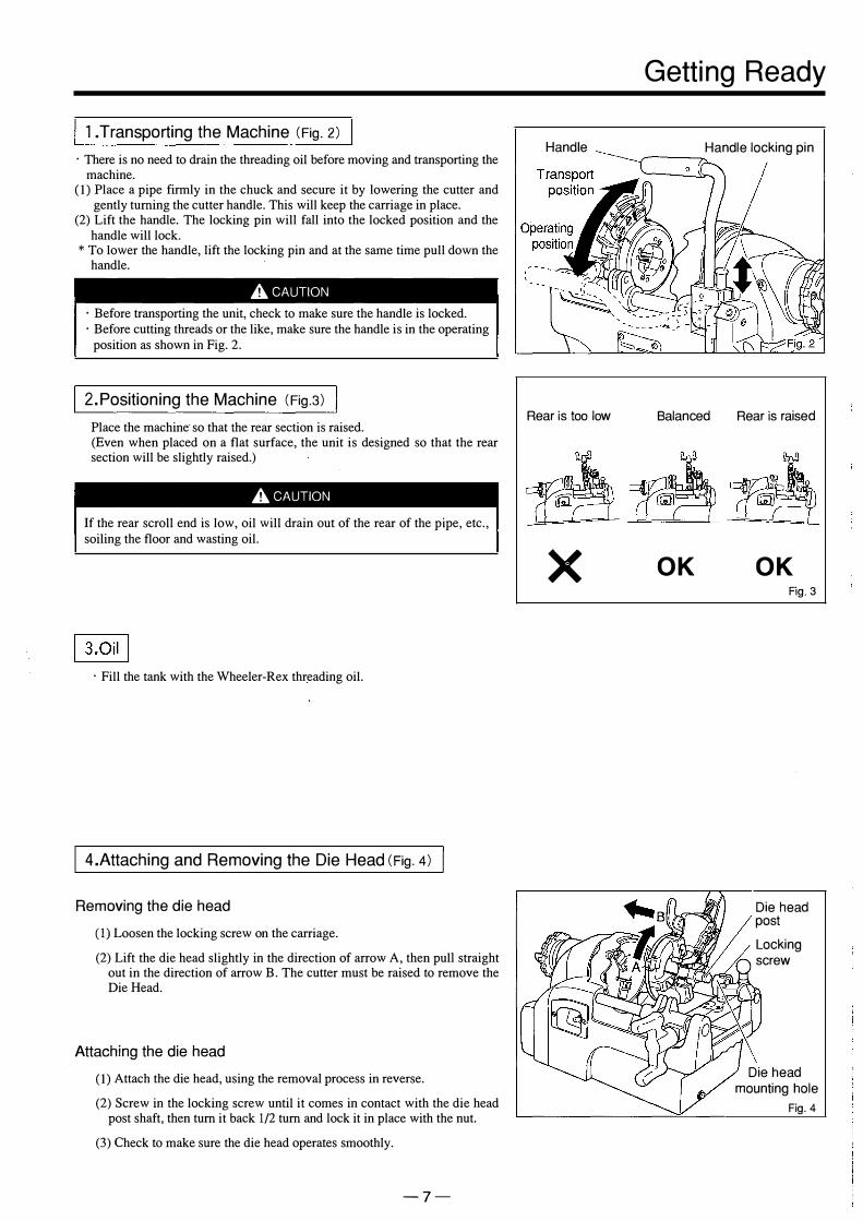
l .Transporting the Machine (Fig. 2)
· There is no need to drain the threading oil before moving and transporting the machine.
(I) Place a pipe firmly in the chuck and secure it by lowering the cutter and gently turning the cutter handle. This will keep the carriage in place.
(2) Lift the handle. The locking pin will fall into the locked position and the handle will lock.
* To lower the handle, lift the locking pin and at the same time pull down the handle.
AcAUTION · Before transporting the unit, check to make sure the handle is locked. · Before cutting threads or the like, make sure the handle is in the operating
position as shown in Fig. 2.
2.Positioning the Machine (Fig.3)
Place the machine so that the rear section is raised. (Even when placed on a flat surface, the unit is designed so that the rear section will be slightly raised.)
AcAUTION
If the rear scroll end is low, oil will drain out of the rear of the pipe, etc., soiling the floor and wasting oil.
· Fill the tank with the Wheeler-Rex threading oil.
4.Attaching and Removing the Die Head (Fig. 4)
Removing the die head
(I) Loosen the locking screw on the carriage.
(2) Lift the die head slightly in the direction of arrow A, then pull straight out in the direction of arrow B. The cutter must be raised to remove the Die Head.
Attaching the die head
(I) Attach the die head, using the removal process in reverse.
(2) Screw in the locking screw until it comes in contact with the die head post shaft, then tum it back 1/2 tum and lock it in place with the nut.
(3) Check to make sure the die head operates smoothly.
-7-
Handle
Rear is too low
x
Getting Ready
Handle locking pin ,...---�
Balanced
OK
Rear is raised
OK Fig. 3
Die head post Locking screw
Die head mounting hole
Fig. 4

Getting Ready
I 5.0perating the Die Head I •Names of Parts
Notch B (for 1 "(25A)) (silver)
Auto Open lever
Die head post
Die CZ)
•setting the Thread Cutting Size
· The die head supplied with standard units can accommodate three pipe sizes: l/2"(15A), 3/4"(20A) and 1"(25A). For l/2"(15A) and 3/4"(20A) pipes, insert the 1/2" (15A)(black) or 3/4"(20A) (black) eccentric pins into the black A 1/2",3/4" notch. For 1"(25A) pipes, the l"(25A) (silver) eccentric pin into the 1"(25A) silver notch. (In this case, the die must also be changed.)
•changing Dies
· The screw pitch is different for l/2"(15A), 3/4"(20A) and 1"(25A), so when the notch positions are changed, the die must also be changed. You should also use the following procedure to change the die when it is worn and needs to be replaced.
(1) Push up the auto-open lever to open the die head.
(2) Remove the positioning pins from the notches and pull the guide set lever in the direction indicated by the arrow to enable Dies @ and @ to be removed.
(3) Lift the die head over to remove Dies <D and ®·
Guide set lever
Fig. 5
Eccentric positioning pins 1 /2" ( 15A) (black) 3/4" (20A) (black) 1" (25A) (silver)
(�-----,�� � ....... , .J
.----------'---'' � Notch A 1 /2" ( 15A) , Notch B 1 "A (25A) (silver) 3/4" (20A) (black) Fig. 6
Fig. 7
-8-

•Attaching the Dies
(1) Use the removal procedure in reverse to attach dies to the die head. Insert the dies into their corresponding die groove on the die head and push them in until they click into place on the notch.
(2) Push up the guide set lever.
*Make sure the die number matches the groove number on the die head. Threading will not be possible if the wrong die is inserted into the die groove.
*Dies come in sets of four. When replacing dies, be sure to replace all four at the same time.
*If it is difficult to pull up the guide set lever, move the die up and down slightly and try again.
•Adjusting the Thread Length
( 1) Push the auto-open lever to open the die head, then loosen the lever stop bolt slightly.
(2) To increase the thread length, move the lever stop toward the reamer. To decrease the thread length, move the lever stop toward the cutter.
(3) Fasten the lever stop bolt tightly.
•Adjusting the Thread Diameter
· The thread diameter can be adjusted for each pipe size.
(1) Loosen the eccentric pin locking bolt slightly.
(2) To increase the thread diameter, turn the eccentric pinto the+ side (clockwise). To decrease the diameter, turn the eccentric pin to the - side (anti-clockwise).
(3) When the adjustment is complete, retighten the eccentric pin locking bolt.
•Adjusting the Thread Diameter Using a Size Adjustment Plate · If the thread diameter cannot be adjusted properly even when the positioning
pin is turned all the way, use the following procedure to replace the size adjustment plate.
( 1) Using a flathead screwdriver, loosen the notch shaft.
(2) Holding the positioning notch in place, remove the notch shaft.
(3) Remove the positioning notch, being careful to make sure the pin and spring beneath do not come out.
(4) Insert one of the size adjustment plates shown in Fig. 1 1 (1) and (2). (5) Insert the spring and pin in the proper hole on the cutting block and hold
them in place with the positioning notch.
(6) Pass the notch shaft through the cutting block and then place the positioning notch and size adjustment plate in position.
(7) Using a flathead screwdriver, fasten the notch shaft securely in place.
- 9 -
Getting Ready
���Ft-size adjustment plate
Fig. 8
Size adjustmentt�Fi��Zj plate Notch shaft
(1) For wider threads (2) For narrower threads
Fig. 11

Getting Ready
Note: When operating the unit, make sure the handle is in the lowered position ("Operating position" in Fig. 2 on Pg. 7).
6.lnserting and Removing Pipes (Fig. 12)
' . AwARNING During operation and immediately after the switch has been set to the OFF position, when the machine is still rotating, do NOT attempt to insert or remove pipes. This could result in an accident or serious injury if you should become caught in the machinery. Before inserting or removing pipes, check to make sure that the machine has stopped moving completely, and remove the power plug from the outlet. Accidents or injuries may result if the unit should begin operating unexpectedly.
(1) Open chuck to a position wider than the pipe diameter, then insert the pipe from the rear chuck. (If the pipe is short, insert it from the front chuck.)
(2) Close the chuck and then, supporting the pipe with your right hand, close the chuck gently with your left hand and align the tip against the pipe. Then fasten the pipe securely in place.
(3) To remove the pipe, turn the hand wheel in the opposite direction to loosen the chuck. Then loosen the rear chuck and remove the pipe.
•Attaching Short Pipes for Thread Cutting (Fig. 13) Clamp the pipe lightly with the chuck and, using the blade of the die, support the end where threads will be cut. Then once again pull the hammer chuck toward you to fasten the pipe tightly in place. This will ensure that the pipe does not vibrate and threads are cut smoothly. However, be sure to fasten the pipe with the chuck no closer than 2.5"(65mm) to the tip end of the chuck.
•Attaching Long Pipes (Fig. 14) When cutting threads on long pipes, use a pipe support to ensure that the pipe does not vibrate due to warping as it rotates, and further to ensure that the machine does not become unstable due to the weight of the pipe.
A WARNING
Failure to use a pipe support may make proper threading impossible and may result in damage to the equipment, accident or injury.
7 .Power Supply (Fig. 15)
·Plug the machine into a power supply that matches its specifications. If an extention cord is used it must be no longer than 50ft(15m) and at least 12/3 in size.
Make sure the unit is grounded properly before attempting to use it. Failure to do so may result in electric shock.
- 10-
Rear P
ush the chuck carrying I handle over
Long pipe
x
At least 2.5"(65mm) Fig. 13
Q Jt�K �-P-
ip
_
e
_
S
_
ta
_
n_d
___ � 14

Getting Ready
AwARNING
Before cutting or threading pipes, be sure to check the following. If anything is out of the ordinary, consult the Troubleshooting table and take the appropriate action as noted in the table. Failure to check and resolve problems may result in accident or injury.
8.Pre-Operational Inspection
(1) Set the switch to the ON position and step on foot switch. · Make sure there is no abnormal noise or odor coming from the motor. · Make sure the pipe is not vibrating. If the pipe is vibrating, etc., fasten it in place again. · Make sure cutting oil is coming out of the die head, and check that the machine is filled with the correct amount of threading oil.
(2) Let the machine idle Jar a few minutes. · Make sure the motor does not heat up excessively, etc.
AwARNING
1 .Always use the recommended type of carbon brushes. · The brake may fail to operate if other carbon brushes are used.
2.Store the unit where it will not be subjected to excessive humidity. · Storing the unit in a humid location for long periods of time may cause an oxide film to form on the motor and prevent the brake from operating properly. Always store the unit in a place with low humidity.
- 11 -

Getting Ready
I 9.Cutting Pipes I (1) As the die head and reamer will not be used when cutting pipes, lift them out
of the way. (2) Determine the position at which the pipe is to be cut, then fasten the pipe
securely. (3) Open the pipe cutter to a position wider than the pipe diameter. Place the
cutter in the pipe as shown in the figure, aligning the blade with the cutting position on the pipe. Then use the handle to move the roller and blade until they rest lightly against the pipe.
(4) Set the switch to the ON position, then tum the cutter handle up to 1/2 tum for each rotation of the pipe (Fig. 17). Avoid cutting with excessive force from the beginning, or the shape of the pipe may become distorted, preventing you from making accurate circular threads. Throughout the process, tum the cutter handle against the pipe lightly and evenly.
A, CAUTION
Make sure the cutter is placed in the proper position before turning the pipe. If the cutter is improperly positioned, the pipe may suffer harmful scratches or the cutter may be damaged.
•special Cut Grinder Precautions We strongly recommend that only the pipe cutter attached to the machine be used to cut pipes that are to be threaded. If another cutting method is used insure that the pipe is cut square.
-12 -
OK Fig.A
x Fig.B
x Fig.C
Fig.18

1 O.Chamfering
After cutting the pipe with the pipe cutter, be sure to use the reamer to chamfer the inside of the pipe before cutting threads.
(1) As the die head and cutters will not be used when chamfering, lift them out of the way.
(2) Pull up the reamer knob to place the reamer in the chamfering position.
(3) Set the switch to the ON position to start the pipe rotating, then use the feed
handle to place the reamer against the pipe. When the pipe has made at least
one complete revolution, remove the reamer from the pipe. This completes the chamfering process. (Fig. 20)
A CAUTION
Do not use excessive force to press the reamer against the pipe. This may produce harmful scratches in the pipe or damage the unit. The reamer blade is extremely sharp. NEVER touch it with your bare hands, as you may be seriously injured.
esefore Cutting Threads I 1 1 .Carriage Protection Mechanism I Attempting to cut threads on pipes that are too short may cause the carriage to strike the headstock, warping or otherwise damaging the unit. Accordingly, the unit is equipped with a carriage anti-collision mechanism. This mechanism protects the machine by automatically stopping the motor just before the carriage strikes the headstock.
(1) As the carriage nears the headstock, a rod is automatically pushed forward.
(2) If the carriage moves any closer, the rod presses the switch, turning off the machine just before the carriage strikes the headstock.
(3) The pipe end allowance is too short, so increase the end allowance and clamp the pipe again.
(See "Attaching Short Pipes for Thread Cutting" on Pg. 10.)
A CAUTION
· Start the thread cutting process with the carriage to the right of the red line on the front support bar.
- 13 -
Getting Ready
... - - -
'
' � '
- l ' , ,\_,' ..,.. _.._ ..
Fig. 21

Getting Ready
I 1 2.Cutting Threads I Lift the cutter and reamer and set the die head to the proper size. Also look over the unit to make sure it is safe to begin threading.
Note: Make sure the handle is in the lowered position (''Operating position" in Fig. 2 on Pg. 7) before beginning the cutting process.
(1) Push up the guide set lever and set the die head to the proper size. Check to make sure that the unit is set to the desired size. (Fig. 22)
To change the size: (Fig. 23)
1. Push the positioning notch in the direction of arrow (1) in Fig. 23.
2. Align the positioning notch to the desired pipe size as displayed on the size indicator plate.
3. Push the positioning notch in the direction of arrow (3), and at the same time insert the positioning pin in the notch groove.
(If necessary, replace the die. See Pg. 8 for the replacement procedure.)
(2) Set the switch to the ON position, step on foot switch. Oil will be supplied from the die head automatically.
(3) Tum the feed handle clockwise and press the die head against the pipe to allow the dies to begin cutting (Fig. 24).
( 4) Once three or four threads have been cut, the remainder will be cut automatically. When the prescribed thread length is reached, the dies will be released by the auto-open lever.
(5) To complete the threading procedure, tum the feed handle anti-clockwise to retract the die head from the pipe.
(6) To continue cutting threads of the same size, lift the guide set lever and check to make sure that the die head is in the proper position each time before beginning the threading process.
•Precautions when Threading (Fig. 25)
(1) When first cutting the pipe with the die: Place the blade of the die gently against the end of the pipe. Placing the blade against the pipe with excessive force may damage the die and shorten its life. When the blade comes in contact with the end of the pipe, initially press it lightly and tum the feed handle clockwise, then gradually increase the amount of force so the unit cuts firmly. Once 3 of 4 threads have been cut, the Die head will feed itself without further pressure.
- 14 -
Blade � Die
D f - .
- -J Pipe - .
Fig. 25
Daily Inspection & Care
AcAUTION
· Before inspecting or performing maintenance on the unit, always set the switch to the OFF position and remove the plug from the outlet. If the unit is left plugged in, it may begin operating unexpectedly, resulting in injury. · If you discover any problems during inspection or maintenance, look up the symptoms in the "Troubleshooting" table and take the appropriate action as noted in the table. Continued use of the unit without correcting the problem may result in heat, smoke or fire and lead to accident or injury.
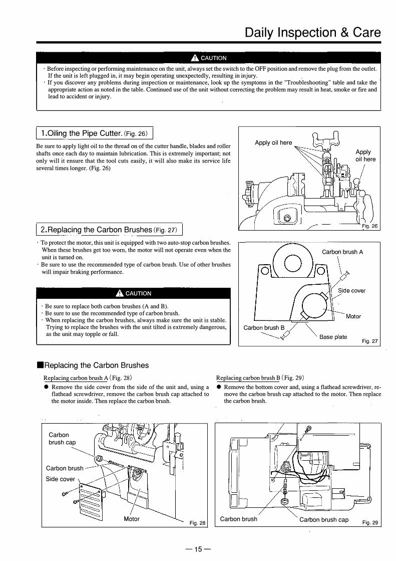
1.0iling the Pipe Cutter. (Fig. 26)
Be sure to apply light oil to the thread on of the cutter handle, blades and roller shafts once each day to maintain lubrication. This is extremely important; not only will it ensure that the tool cuts easily, it will also make its service life several times longer. (Fig. 26)
2.Replacing the Carbon Brushes (Fig. 27)
· To protect the motor, this unit is equipped with two auto-stop carbon brushes. When these brushes get too worn, the motor will not operate even when the unit is turned on. · Be sure to use the recommended type of carbon brush. Use of other brushes will impair braking performance.
AcAUTION
· Be sure to replace both carbon brushes (A and B). · Be sure to use the recommended type of carbon brush. · When replacing the carbon brushes, always make sure the unit is stable. Trying to replace the brushes with the unit tilted is extremely dangerous, as the unit may topple or fall.
Apply oil here
Carbon brush B ---------/)
Apply oil here
Carbon brush A
�
Fig. 27
•Replacing the Carbon Brushes
Replacing carbon brush A (Fig. 28) Replacing carbon brush B (Fig. 29) • Remove the side cover from the side of the unit and, using a
flathead screwdriver, remove the carbon brush cap attached tothe motor inside. Then replace the carbon brush.
Carbon brush cap
Carbon brush Side cover
Motor Fig. 28
-15-
• Remove the bottom cover and, using a flathead screwdriver, remove the carbon brush cap attached to the motor. Then replace the carbon brush.
D
D B-Carbon brush Carbon brush cap Fig. 29
Daily Inspection & Care
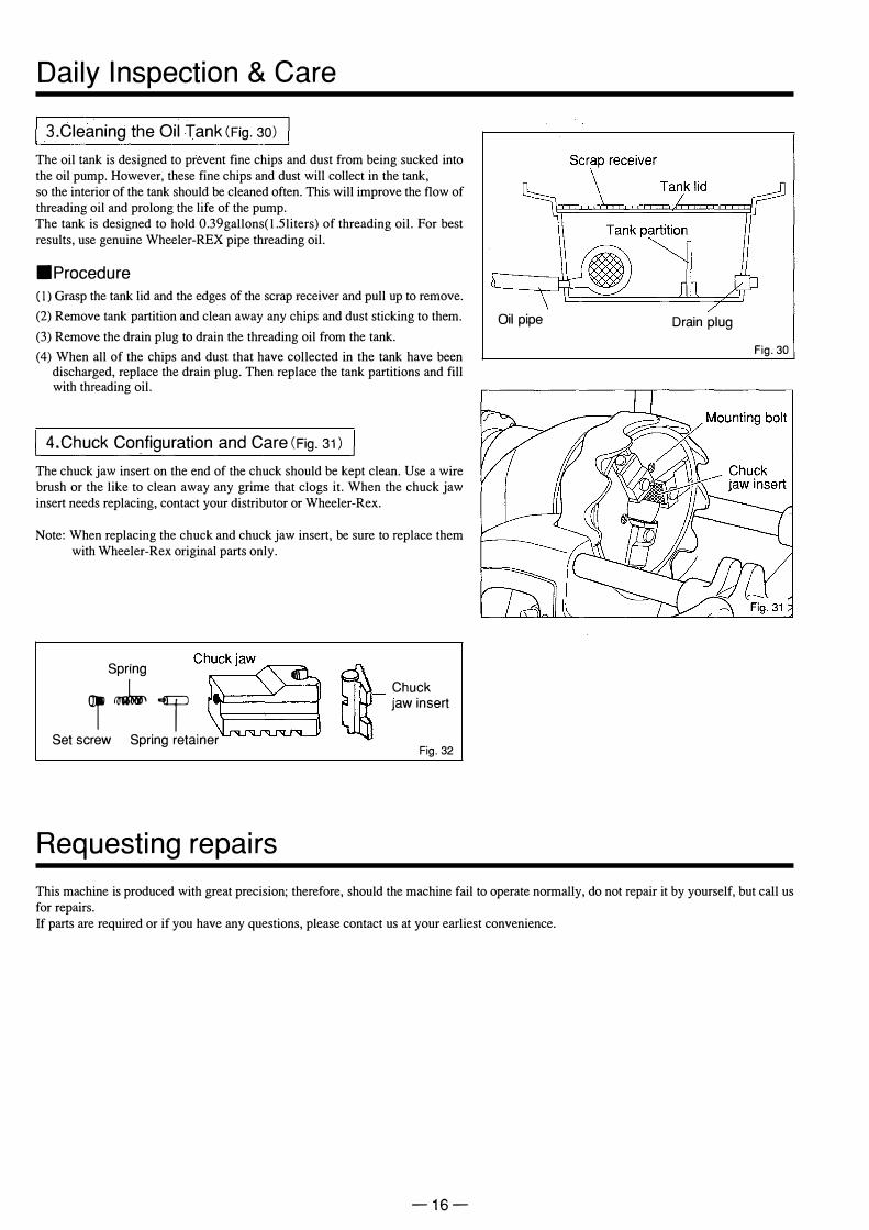
I 3.Cleaning the Oil Tank(Fig. 30) I The oil tank is designed to prevent fine chips and dust from being sucked into the oil pump. However, these fine chips and dust will collect in the tank, so the interior of the tank should be cleaned often. This will improve the flow of threading oil and prolong the life of the pump. The tank is designed to hold 0.39gallons( l .5liters) of threading oil. For best results, use genuine Wheeler-REX pipe threading oil.
•Procedure(I) Grasp the tank lid and the edges of the scrap receiver and pull up to remove.
(2) Remove tank partition and clean away any chips and dust sticking to them.
(3) Remove the drain plug to drain the threading oil from the tank.
(4) When all of the chips and dust that have collected in the tank have been discharged, replace the drain plug. Then replace the tank partitions and fill with threading oil.
4.Chuck Configuration and Care (Fig. 31)
The chuck jaw insert on the end of the chuck should be kept clean. Use a wire brush or the like to clean away any grime that clogs it. When the chuck jaw insert needs replacing, contact your distributor or Wheeler-Rex.
Note: When replacing the chuck and chuck jaw insert, be sure to replace them with Wheeler-Rex original parts only.
Spring
i..J.., ISet screw Spring retainer
Requesting repairs
� Chuck � iawinsert
Fig. 32
Oil pipe Drain plug
Fig. 30
This machine is produced with great precision; therefore, should the machine fail to operate normally, do not repair it by yourself, but call us for repairs. If parts are required or if you have any questions, please contact us at your earliest convenience.
- 16 -

Before requesting repairs and services
A CAUTION If any problems are not dealt with below, do not attempt to overhaul or repair the unit by yourself.If repairs are performed by untrained or unskilled personnel, optimum performance cannot be attained, and accidents and injuries may occur.
Problem Possible Causes Corrective measures
The machine If the motor The power supply plug is Insert the power supply plug into the disconnected. plug socket.
does not operate is not The carbon brushes are
even when the running. Replace with new ones according to the worn out. procedures on Pg.15.
switch is turned Voltage is low. Check the voltage. ON
The motor is burned out. Repair is necessary.
The switch is damaged. Repair is necessary. If the motor The gear is broken. Repair is necessary. is running.
Rotation of the main shaft is Voltage is low. Check the voltage. defective. The motor is burned out. Repair is necessary.
Not stopped immediately even The carbon brushes are Replace with new ones according to the
in turning OFF the switch. worn out. procedures on Pg.15.
The machine does not stop The lead from the motor has Repair is necessary. immediately even when the become disconnected. switch is turned OFF.
Oil is not supplied correctly. The amount of oil is low. Replenish the oil.
Tank is clogged with chips. Remove chips in the oil tank.
The die head is not fitted Place the die head in the correctly. correct position.
Oil drips from the back of The rear chuck is too low. Raise the rear chuck. the pipe, etc.
The die head cannot be Chips are in the way. Remove chips stuck to the attached. die head fitting shaft and hole.
A pipe on the tank top cover Remove the pipe, etc. is in the way.
Moving parts do not move Chips are clogging up Remove chips. smoothly the machine.
The dies do not engage the The dies are worn out. Replace with new ones. pipe properly.
The dies are chipped. Replace with new ones.
The dies have not been Insert the dies according to the placed in the correct position. number on the die head.
Threads are of Thick, Thin The die head is not Adjust the die head according to adjusted correctly. the procedures on P.9.
poor quality. Long, Short The die head is not Adjust the die head according to
adjusted correctly. the procedures on P.9.
The dies are worn out. Replace with new ones.
The dies are chipped. Replace with new ones.
Thread cutting oil has deteriorated. Replace with new thread cutting oil. The dies have not been Insert the dies according to the placed in the correct position. number on the die head.
- 17 -