pipe dream for powder metal manufacturing
TRANSCRIPT
30 MPR March/April 201030 MPR March/April 2010 0026-0657/10 ©2010 Elsevier Ltd. All rights reserved.
PIM2010
Pipe dream for powder metal manufacturingThe potential of powder metallurgy as a disruptive technology may strike some chords in the established pipe-making industries if a piece of German research is developed in the future...
Industrial production of metal-lic pipes is currently dominated by rolling and pressing; welding, and continuous casting [1]. But however
dominant they appear, they have to be seen also in terms of equipment and operating costs and their sometimes limited choice of available materials.
Powder metallurgy, by comparison, offers a low-cost manufacturing route via the extrusion of modified MIM-feedstocks, [2, 3] to produce high-quality linear struc-tures. A research team in Germany, thought this an interesting proposition and worth closer examination.
Producing metallic profiles by extrusion techniques still is a niche process. Due to the specific process conditions, extrusion requires the use of PM feedstocks – compositions of metal powder, binders and lubricants.
When exiting the forming tool or nozzle of the extrusion system, the “soft” extruded hollow-profile string can lose its geometry simply by deforming – collapsing under the force of gravity. This sets a real challenge, especially when thin-walled profiles are the aim. To avoid this loss of geometric quality it is possible either to run the process with tight control of the heat balance – temperatures and extrusion speed – or to calibrate the extrudate leaving the forming tool. Finding the exact process parameters for one material would mean a substantial effort and will not, even
then, avoid such problems as quality changes in the feedstock raw material. Calibration of the product’s geometry and surface after extrusion is a better way to guarantee quality. During calibration the extrudate is cooled and supported until it has gained enough strength to keep its geometric form as a green part.
This is a very new area for powder metallurgy and results are few, so there is great interest in production techniques. Compared to the extrusion of plastics there is a large potential for improve-ment of both processes and products.
During the different tests a circular pipe-shaped profile with defined dimen-sions was extruded with and without the different calibration devices. The results show their influence on dimensional sta-bility and which is the most promising of
the calibration approaches adopted. All tests were carried out with a Brabender 19 mm single-screw extruder with four independently controllable temperature zones [4]. All tests used feedstock com-positions based on steel or copper pow-der, normally used for metal injection moulding (MIM), slightly adapted for extrusion.
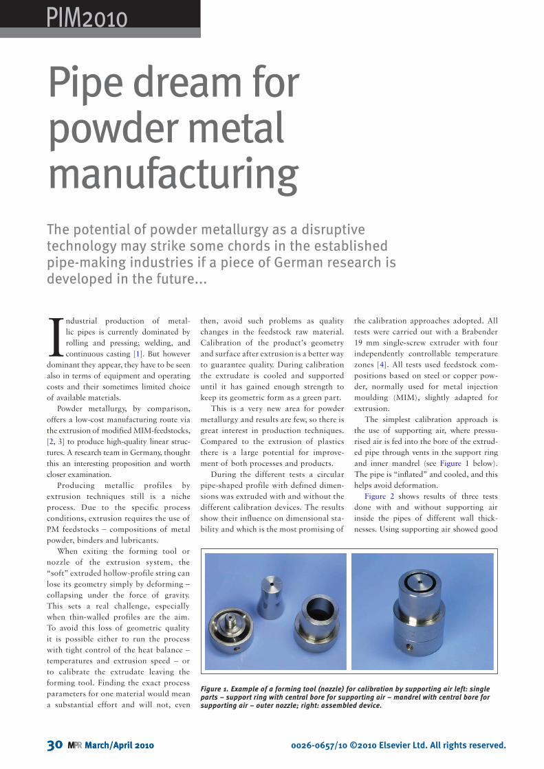
The simplest calibration approach is the use of supporting air, where pressu-rised air is fed into the bore of the extrud-ed pipe through vents in the support ring and inner mandrel (see Figure 1 below). The pipe is “inflated” and cooled, and this helps avoid deformation.
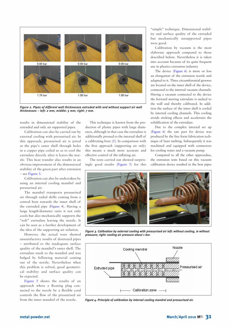
Figure 2 shows results of three tests done with and without supporting air inside the pipes of different wall thick-nesses. Using supporting air showed good
Figure 1. Example of a forming tool (nozzle) for calibration by supporting air left: single parts – support ring with central bore for supporting air – mandrel with central bore for supporting air – outer nozzle; right: assembled device.
March/April 2010 MPR 31metal-powder.net
results in dimensional stability of the extruded and only air supported pipes.
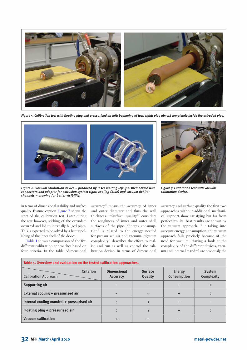
Calibration can also be carried out by external cooling with pressurised air. In this approach, pressurised air is jetted at the pipe’s outer shell through holes in a copper pipe coiled so as to cool the extrudate directly after it leaves the noz-zle. This heat transfer also results in an obvious improvement of the dimensional stability of the green part after extrusion – see Figure 3.
Calibration can also be undertaken by using an internal cooling mandrel and pressurised air.
The mandrel transports pressurised air through radial drills coming from a central bore towards the inner shell of the extruded pipe (Figure 4). Having a large length/diameter ratio it not only cools but also mechanically supports the “soft” extrudate leaving the nozzle. It can be seen as a further development of the idea of the supporting air solution.
However, the actual tests showed unsatisfactory results of destroyed pipes – attributed to the inadequate surface quality of the mandrel’s outer shell. The extrudate stuck to the mandrel and was bulged by following material coming out of the nozzle. Nevertheless when this problem is solved, good geometri-cal stability and surface quality can be expected.
Figure 5 shows the results of an approach where a floating plug con-nected to the nozzle by a flexible cord controls the flow of the pressurised air from the inner mandrel of the nozzle.
This technique is known from the pro-duction of plastic pipes with large diam-eters, although in that case the extrudate is additionally pressed to the internal shell of a calibrating bore [5]. In comparison with the first approach (supporting air only) this means a much more accurate and effective control of the inflating air.
The tests carried out showed surpris-ingly good results (Figure 5) for this
“simple” technique. Dimensional stabil-ity and surface quality of the extruded but mechanically unsupported pipes were good.
Calibration by vacuum is the most elaborate approach compared to those described before. Nevertheless it is taken into account because of its quite frequent use in plastics extrusion industry.
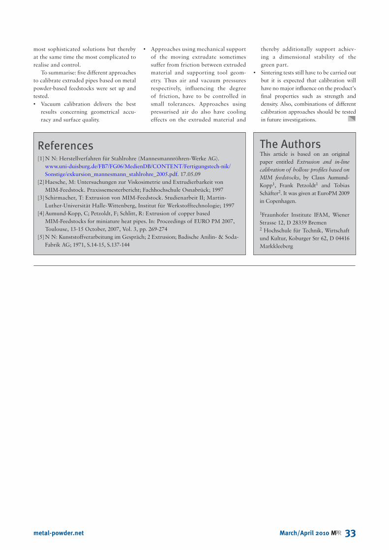
The device (Figure 6) is more or less an elongation of the extrusion nozzle and adapted to it. Three circumferential grooves are located on the inner shell of the device, connected to the internal vacuum channels. Having a vacuum connected to the device the forward moving extrudate is sucked to the wall and thereby calibrated. In addi-tion the surface of the inner shell is cooled by internal cooling channels. This cooling avoids sticking effects and accelerates the solidification of the extrudate.
Due to the complex internal set up (Figure 6) the raw part for device was produced by the free form fabrication tech-nique of laser melting. Subsequently it was machined and equipped with connectors for cooling water and a vacuum pump.
Compared to all the other approaches, the extrusion tests based on this vacuum calibration device resulted in the best pipes
Figure 3. Calibration by external cooling with pressurised air left: without cooling, ie without pressure; right: cooling air pressure about 1 bar.
Figure 2. Pipes of different wall thicknesses extruded with and without support air wall thicknesses – left: 2 mm; middle: 5 mm; right: 7 mm.
Figure 4. Principle of calibration by internal cooling mandrel and pressurised air.
32 MPR March/April 2010 metal-powder.net
in terms of dimensional stability and surface quality. Feature caption Figure 7 shows the start of the calibration test. Later during the test however, sticking of the extrudate occurred and led to internally bulged pipes. This is expected to be solved by a better pol-ishing of the inner shell of the device.
Table 1 shows a comparison of the five different calibration approaches based on four criteria. In the table “dimensional
accuracy” means the accuracy of inner and outer diameter and thus the wall thickness. “Surface quality” considers the roughness of inner and outer shell surfaces of the pipe. “Energy consump-tion” is related to the energy needed for pressurised air and vacuum. “System complexity” describes the effort to real-ise and run as well as control the cali-bration device. In terms of dimensional
accuracy and surface quality the first two approaches without additional mechani-cal support show satisfying but far from perfect results. Best results are shown by the vacuum approach. But taking into account energy consumption, the vacuum approach fails precisely because of the need for vacuum. Having a look at the complexity of the different devices, vacu-um and internal mandrel are obviously the
Figure 6. Vacuum calibration device – produced by laser melting left: finished device with connectors and adapter for extrusion system right: cooling (blue) and vacuum (white) channels – drawing for better visibility.
Figure 7. Calibration test with vacuum calibration device.
Table 1. Overview and evaluation on the tested calibration approaches.
CriterionCalibration Approach
Dimensional
Accuracy
Surface
Quality
Energy
Consumption
System
Complexity
Supporting air - - + +
External cooling + pressurised air - - + )
internal cooling mandrel + pressurised air ) ) + -
Floating plug + pressurised air ) ) + )
Vacuum calibration + + - -
Figure 5. Calibration test with floating plug and pressurised air left: beginning of test; right: plug almost completely inside the extruded pipe.
March/April 2010 MPR 33metal-powder.net
most sophisticated solutions but thereby at the same time the most complicated to realise and control.
To summarise: five different approaches to calibrate extruded pipes based on metal powder-based feedstocks were set up and tested. • Vacuum calibration delivers the best
results concerning geometrical accu-racy and surface quality.
• Approaches using mechanical support of the moving extrudate sometimes suffer from friction between extruded material and supporting tool geom-etry. Thus air and vacuum pressures respectively, influencing the degree of friction, have to be controlled in small tolerances. Approaches using pressurised air do also have cooling effects on the extruded material and
thereby additionally support achiev-ing a dimensional stability of the green part.
• Sintering tests still have to be carried out but it is expected that calibration will have no major influence on the product’s final properties such as strength and density. Also, combinations of different calibration approaches should be tested in future investigations.
References[1] N N: Herstellverfahren für Stahlrohre (Mannesmannröhren-Werke AG).
www.uni-duisburg.de/FB7/FG06/MedienDB/CONTENT/Fertigungstech-nik/Sonstige/exkursion_mannesmann_stahlrohre_2005.pdf. 17.05.09
[2] Haesche, M: Untersuchungen zur Viskosimetrie und Extrudierbarkeit von MIM-Feedstock. Praxissemesterbericht; Fachhochschule Osnabrück; 1997
[3] Schirmacher, T: Extrusion von MIM-Feedstock. Studienarbeit II; Martin-Luther-Universität Halle-Wittenberg, Institut für Werkstofftechnologie; 1997
[4] Aumund-Kopp, C; Petzoldt, F; Schlitt, R: Extrusion of copper based MIM-Feedstocks for miniature heat pipes. In: Proceedings of EURO PM 2007, Toulouse, 13-15 October, 2007, Vol. 3, pp. 269-274
[5] N N: Kunststoffverarbeitung im Gespräch; 2 Extrusion; Badische Anilin- & Soda-Fabrik AG; 1971, S.14-15, S.137-144
The AuthorsThis article is based on an original paper entitled Extrusion and in-line calibration of hollow profiles based on MIM feedstocks, by Claus Aumund-Kopp1, Frank Petzoldt1 and Tobias Schäfter2. It was given at EuroPM 2009 in Copenhagen.
1Fraunhofer Institute IFAM, Wiener Strasse 12, D 28359 Bremen2 Hochschule für Technik, Wirtschaft und Kultur, Koburger Str 62, D 04416 Markkleeberg