pinellas county department of public works · 2013-08-23 · pinellas county cadd standards manual...
TRANSCRIPT

P I N E L L A S C O U N T Y C A D D S T A N D A R D S M A N U A L
Pinellas County
Department of Public Works
CADD STANDARDS MANUAL
for
Land Survey and Civil Engineering
Effective: 10/01/07
Version 1.2
10/30/2007 1-1
P I N E L L A S C O U N T Y C A D D S T A N D A R D S M A N U A L
01-01-2005 1-2
Authors: Larry D. Solien Jr., Pinellas County Public Works, Asset Management Division Ed L. Lachman Pinellas County Public Works, Capital Support Division Dave Miles Pinellas County Public Works, Land Survey and Mapping Division Comey Wright, PLS Pinellas County Public Works, Land Survey and Mapping Division
Contributing Credits:
Pinellas County TAC Members: Tim Clark Pinellas County Public Works, Transportation Division Fred Roose Pinellas County Public Works, Surface Water Division Brent Hall Pinellas County Public Works, Civil Site Division Robert Plant Pinellas County Public Works, Traffic Division Abby Bryant Pinellas County Utilities, Engineering Division Matt Miller Pinellas County Utilities, Engineering Division Shawn Dillon Pinellas County BCCIS
Florida Department of Transportation (F.D.O.T.) A very special Thank You to the following Professionals for their continued support and collaboration to the Pinellas County CADD Standards Development: Bill Gerry CADD Applications Support Specialist Bruce Dana CADD Support Manager Warren Clary Sr. Programmer for PEDDS
P I N E L L A S C O U N T Y C A D D S T A N D A R D S M A N U A L
01-01-2005 1-3
Table of Contents
CHAPTER 1 - INTRODUCTION..............................................................................1-11
Purpose and Usage..................................................................................................1-11
Scope ........................................................................................................................1-11
General......................................................................................................................1-11
CHAPTER 2 - AUTOCAD STANDARDS ................................................................2-13
PC Standard Template Files (4-) .............................................................................2-13 PC Standard Object’s Modified ...........................................................................2-13 PC Standard Template File List ..........................................................................2-14
Layers (4-74) .............................................................................................................2-14 Named Layer Filters (4-75).....................................................................................2-15
Named Layer Filter List Table .............................................................................2-15
AutoCAD Object Styles (4-77 – 4-84) ......................................................................2-15 Dimension Styles (4-77) .........................................................................................2-15
Named Dimension Style List Table .....................................................................2-15 Text Styles (4-80) ...................................................................................................2-16 Fonts (4-82) ............................................................................................................2-16
Named Text Style List Table ...............................................................................2-17 Text Size and Spacing (4-83) .................................................................................2-17
Table of Standard Text Sizes – B-Size ...............................................................2-17 Table of Standard Text Sizes – D-Size ...............................................................2-18
Line Types (4-84) ......................................................................................................2-18 System Variables for Linetypes .............................................................................2-18 PC Custom Line Type Files ....................................................................................2-19
Line Weight (4-85) ....................................................................................................2-19
PC Color Table (4-) ...................................................................................................2-20
Plotting with AutoCAD and Creating Plot Files .....................................................2-21 Plots........................................................................................................................2-21 Plotter Device Configuration Files (*.pc3) ...............................................................2-21
PC Standard Plotter Device Configuration Files (*.pc3) ......................................2-21 Page Setup Configuration Files (4-.........................................................................2-22
P I N E L L A S C O U N T Y C A D D S T A N D A R D S M A N U A L
01-01-2005 1-4
PC Standard Page Setups ..................................................................................2-23 Plot Borders............................................................................................................2-23 Plot Style Tables (*.ctb) ..........................................................................................2-24
PC Standard Plot style tables..............................................................................2-24 PC Standard Shared Full/half-size Plot style table settings: ...............................2-24 PCEng Standard Full/half-size Plot style table settings:......................................2-25 PCSurv Standard Full/half-size Plot style table settings:.....................................2-26
Plotting to a Plot File (*.plt) .....................................................................................2-27 Plotting to a PDF File (*.pdf) ...................................................................................2-27
CHAPTER 3 - LAND DESKTOP STANDARDS (LDT)..............................................2-29
LDT Drawing Setup Files .........................................................................................2-29
User Preferences Support Paths: ...........................................................................2-30 Compatible Image File Types .................................................................................2-33
The Land Desktop Project .......................................................................................2-34 The Land Desktop Project Directory Structure .......................................................2-34 Land Desktop Project Creation...............................................................................2-35
Supporting Documention for CAD TAC members: ..............................................2-36 Land Desktop Drawing Creation .............................................................................2-36
Creating Projects Outside of AutoCAD Land Desktop .........................................2-37
The Standard Engineering Project Management Directory ..................................2-37
Standard File Names................................................................................................2-39 Standard File name extensions ..............................................................................2-39 File Naming Convention EXAMPLE – Model Space Drawing (Multi-User) .............2-39 File Naming Convention EXAMPLE – Model Space Drawing (Single-User)...........2-40 File Naming Convention EXAMPLE – Model Space Drawing (Paper Space).........2-40 File Names for AutoCAD (Paperspace) files by Contract Plan Set Disciplines.......2-42
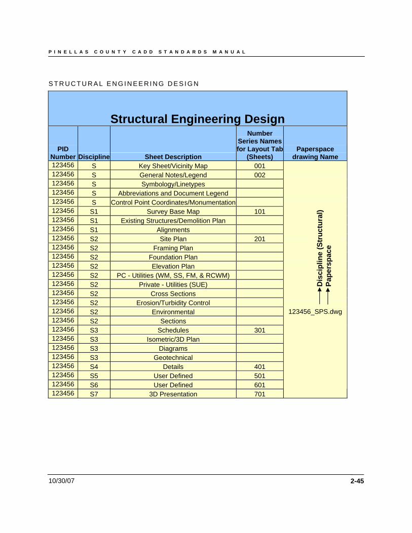
Land Survey and Mapping Division.....................................................................2-42 Public Works - Engineering Design Division .......................................................2-43 Utilities - Engineering Design Division.................................................................2-44 Structural Engineering Design.............................................................................2-45 Architectural Design ............................................................................................2-46
File Names for AutoCAD (Model Space) files by Contract Plan Set Disciplines .....2-47 Land Survey and Mapping Division.....................................................................2-47
Land Survey and Mapping Division – File Diagram ................................................2-48 Public Works - Engineering Design Division .......................................................2-49
Public Works – Engineering Design Divison – File Diagram...................................2-50 Utilities - Engineering Design Division.................................................................2-52
P I N E L L A S C O U N T Y C A D D S T A N D A R D S M A N U A L
01-01-2005 1-5
Utilities Engineering Design Division – File Diagram ..............................................2-53 Structural Engineering Design.............................................................................2-54
Structural Engineering Design – File Diagram........................................................2-56 Architectural Design ............................................................................................2-57
Architectural Design – File Diagram .......................................................................2-58 File Names for AutoCAD (Plot) files by Contract Plan Set Disciplines....................2-59 File Names for AutoCAD (DWF ePlot) files by Contract Plan Set Disciplines.........2-59
Raster Data File Naming Convention .....................................................................2-60 File Names for AutoCAD & Raster Design (Aerial Image) files by Contract Plan Set Disciplines: .............................................................................................................2-60 Auotdesk Raster Design Supported Image file Formats .........................................2-61 World File ...............................................................................................................2-61
CHAPTER 4 - LAND SURVEY AND MAPPING DIVISION .......................................2-63
Points ........................................................................................................................2-63 Points by Range .....................................................................................................2-63 Point Format ...........................................................................................................2-63 Point Groups...........................................................................................................2-63 Point Label Styles ...................................................................................................2-64 Point Code Standards.............................................................................................2-65
Data Points and Symbols Layer Designation ........................................................2-72 String Commands...................................................................................................2-95 Graphic Symbols ....................................................................................................2-96
Figures Layer Destination and Use Control...........................................................2-96
ASCII File Format .....................................................................................................2-99 SAMPLE Format.....................................................................................................2-99
Field Book Files...................................................................................................... 2-100
Alignments.............................................................................................................. 2-100 Standard Construction Alignments ....................................................................... 2-100 Standard Transition Alignments............................................................................ 2-100 Standard Roadway Alignments – Station Format, Station Labels......................... 2-101 Standard Roadway Alignments –Station Labels ................................................... 2-102 Alignment Offset Setting - Add and/or Modify the Layer Names.......................... 2-103 Alignment Station Label Setting............................................................................ 2-104 Alignments Labels & Offset functions display ....................................................... 2-105
DTM (Digital Terrain Model)................................................................................... 2-106
P I N E L L A S C O U N T Y C A D D S T A N D A R D S M A N U A L
01-01-2005 1-6
Pipeworks ............................................................................................................... 2-107 Pipe Alignments.................................................................................................... 2-107
Labels...................................................................................................................... 2-108 Point Labels.......................................................................................................... 2-108 Contour Labels ..................................................................................................... 2-109
CHAPTER 5 - CIVIL ENGINEERING (LDT) ........................................................... 2-116
Points ...................................................................................................................... 2-116 Points by Range ................................................................................................... 2-116 Point Format ......................................................................................................... 2-116 Point Groups......................................................................................................... 2-116 Point Label Styles ................................................................................................. 2-117
Alignments.............................................................................................................. 2-118 Standard Construction Alignments ....................................................................... 2-118 Standard Transition Alignments............................................................................ 2-118 Standard Roadway Alignments – Station Format, Station Labels......................... 2-119 Standard Roadway Alignments – Station Labels .................................................. 2-120 Alignment Offset Setting - Add and/or Modify the Layer Names.......................... 2-121 Alignment Station Label Setting............................................................................ 2-122 Alignments Labels & Offset functions display ....................................................... 2-123
Engineering Roadway Template Alignments....................................................... 2-124 Roadway Template Alignments – Description of function..................................... 2-124 Material Table Editor............................................................................................. 2-125 Point Code Table Editor........................................................................................ 2-126 Points Code Table List.......................................................................................... 2-127 Roadway Template Naming Convention .............................................................. 2-128
Pipeworks ............................................................................................................... 2-129 Pipe Alignments.................................................................................................... 2-129
Terrain DTM Model ................................................................................................. 2-129 Surface Naming Convention................................................................................. 2-129 Building a Surface................................................................................................. 2-130 Adding point Groups to a Surface Model .............................................................. 2-131 Create Breaklines from Figures ............................................................................ 2-132 Breakline Data Creation........................................................................................ 2-132 Contour Styles Manager ....................................................................................... 2-133
Profiles .................................................................................................................... 2-134 Profile Settings...................................................................................................... 2-135
P I N E L L A S C O U N T Y C A D D S T A N D A R D S M A N U A L
01-01-2005 1-7
Existing Ground Layer Settings (EG).................................................................... 2-136 Finished Ground Layer Settings (FG) ................................................................... 2-136 Profile Labels Settings .......................................................................................... 2-138 Layer Prefix (by Alignment) [“*_”].......................................................................... 2-138 Profile Label Text (Abbreviations)......................................................................... 2-139 Text Style - (Set Current “L200”, based on scale) ................................................ 2-139 Creating a Profile - Profile Generator Settings...................................................... 2-139 Grid Creation – Profile Import Grid ....................................................................... 2-139
Working with Pipes ................................................................................................ 2-140 Pipeworks ............................................................................................................. 2-140 Pipes Settings Editor ............................................................................................ 2-141 Pipes Drafting Labels – Plan & Profile .................................................................. 2-142 Structure/Node Drafting Labels ............................................................................ 2-144 Pipes Layers Data - Plan, Profile & X-Section ...................................................... 2-146 Scale Exaggeration Structure (Node) and Pipe Data Values................................ 2-147 Pipe Data Settings ................................................................................................ 2-147 Pipe Slope Control (Min. & Max.).......................................................................... 2-148 Select Coefficient Table........................................................................................ 2-148 Structure Library Editor......................................................................................... 2-150
Structure Library Editor Dialog Box ................................................................... 2-150 Pipes - Run Editor Calculations Setting ................................................................ 2-151
Pipes – Run Editor Setting Dialog Box.............................................................. 2-151 Pipes – Range Design Settings ............................................................................ 2-152 Hydraulic Units...................................................................................................... 2-153 Precision Settings ................................................................................................. 2-154 Conceptual Pipes.................................................................................................. 2-154 Finish Draft Pipes ................................................................................................. 2-155
Cross Sections ....................................................................................................... 2-156 Template Definition and Overview........................................................................ 2-156 PC Standard Roadway Template Folder .............................................................. 2-156 Template Path ...................................................................................................... 2-156
Future - Sheet Manager ......................................................................................... 2-157
Future - Import/Export of LandXML...................................................................... 2-158
CHAPTER 6 - CADD QUALITY ASSURANCE / QUALITY CONTROL.................. 2-161
Pinellas County Civil Engineering Standards Conformance.............................. 2-161
Autodesk Standards Monitoring Extension......................................................... 2-161 Example of Non-Compliant Output Report ........................................................... 2-164
P I N E L L A S C O U N T Y C A D D S T A N D A R D S M A N U A L
01-01-2005 1-8
Example of Compliant Report ............................................................................... 2-165
Areas of Responsibility ......................................................................................... 2-165
CHAPTER 7 - FUTURE PROJECT JOURNAL FILES.......................................... 2-167
Future - Project Journal Guidelines...................................................................... 2-167
Future - Example of CADD Project Index file:...................................................... 2-168 PROJECT INDEX FILE..................................................................................... 2-168 PROJECT DESCRIPTION................................................................................ 2-168 SCOPE OF WORK: .......................................................................................... 2-168
Current - Example of CADD Project Index file:.................................................... 2-169 Example of “Project Journal.txt” file................................................................... 2-169
CHAPTER 8 - FUTURE PROJECT PACKAGING FOR ELECTRONIC SUBMITTAL ...2-172
Purpose................................................................................................................... 2-172
File Formats and Standards .................................................................................. 2-172 Current PC Standard Software Versions: ............................................................. 2-172
Project Components .............................................................................................. 2-172
Contents of the Complete Delivery Package ....................................................... 2-173
Authentication of the Electronic Files .................................................................. 2-173
Media Requirements .............................................................................................. 2-173
Electronic Data Submittal Checklist ..................................................................... 2-173
CHAPTER 9 - CADD STANDARD LAYERS........................................................... 2-176
Existing Layer Table – Pinellas County Land Survey and Mapping Division ...2-176
Proposed Layer Table – Pinellas County Civil Engineering Design Standard..2-186
Land Desktop – Pinellas County Layer Naming Standard.................................. 2-195
Symbology Block Library ...................................................................................... 2-201
New Symbol Addition Procedure.......................................................................... 2-202 Symbol Library Examples ..................................................................................... 2-202
P I N E L L A S C O U N T Y C A D D S T A N D A R D S M A N U A L
01-01-2005 1-9
MOT (Movement of Traffic) Symbol Category................................................... 2-203 Proposed Symbol Category .............................................................................. 2-206 SIGNS Symbol Category .................................................................................. 2-213 PCSurv - Existing Land Survey and Mapping Division Symbols ....................... 2-219
Drawing Examples ................................................................................................. 2-220

P I N E L L A S C O U N T Y C A D D S T A N D A R D S M A N U A L
01-01-2005 1-10
Chapter 1
Introduction
10/30/2007 1-11
Chapter 1 - Introduction Purpose The electronic files created during the process of developing a Computer Aided Design and Drafting (CADD) project for Pinellas County (from here on referred to as “PC”) are to be shared and referenced by many different individuals and must satisfy various needs. The electronic files must be shareable in a format that most, if not all, parties can utilize. Therefore, CADD processes must be established for disciplines that share in the CADD development workflow. This CADD Standards Manual outlines the required standards, conventions and formats necessary to ensure the most usable CADD data set to the foreseeable customers of the CADD data, while providing the producer / developer of the CADD data information necessary to accomplish the task. Scope This CADD Standards Manual sets forth supplemental guidelines to the Pinellas County – Public Works CADD Project Administration Manual. The material presented within this guideline will be monitored as a critical requirement under the CADD Quality Assurance plan. This document is written for CADD users producing plans and maps for the County. It provides the guidelines to produce electronic CADD files according to the County CADD standards in conjunction with PC CADD software. General Chapter 334 of the Florida Statues, known as the Florida Transportation Code, establishes the responsibilities of the State, Counties, and Municipalities for the planning and development of the transportation systems serving the people of Florida, with the objective of assuring development of an integrated, balanced statewide system. The Code's purpose is to protect the safety and general welfare of the people of the State and to preserve and improve all transportation facilities in Florida. Under Section 334.044(2), the Code sets forth the powers and duties of Pinellas County in conjunction with the Department of Transportation to develop and adopt uniform minimum standards and criteria for the design, construction, maintenance, and operation of public roads. The guidelines in this County CADD Project Administration Manual and the FDOT Production Criteria represent minimum requirements that must be met for the development of County CADD projects. While the guidelines contained in this writing provide a basis for uniform CADD practice for County projects, precise rules that would apply to all possible situations that may arise are impossible to give. Situations will exist where these standards will not apply. If variances from the County CADD Project Administration Manual or County CADD Standards Manual are necessary for a project, they must be approved in writing by the Project Manager and documented in the Project Journal file as defined herein. NOTE: The 2000 Florida Department of Transportation CADD Production Criteria is published as a complete revision to the 1996 Roadway CADD Standards Handbook.
P I N E L L A S C O U N T Y C A D D S T A N D A R D S M A N U A L
01-01-2005 1-12
Chapter 2
AutoCAD Standard
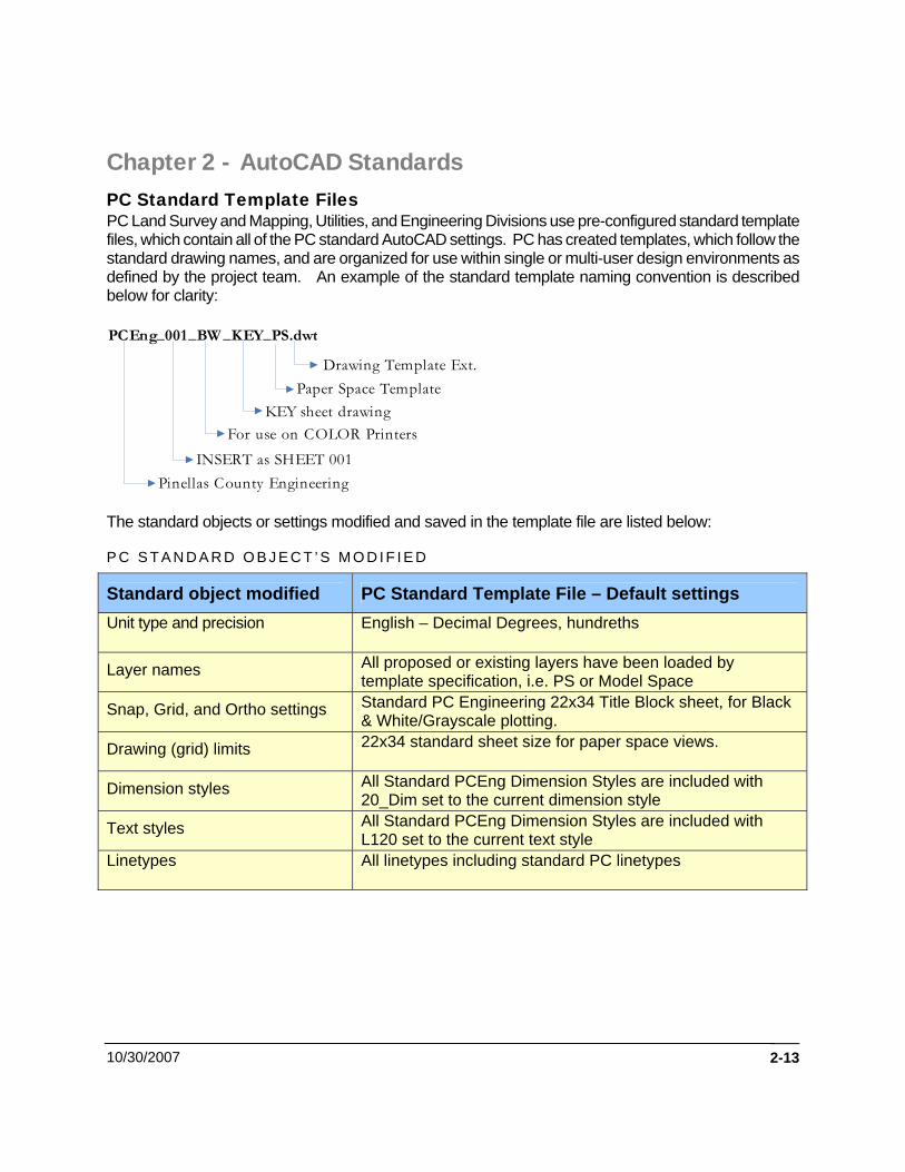
Chapter 2 - AutoCAD Standards PC Standard Template Files PC Land Survey and Mapping, Utilities, and Engineering Divisions use pre-configured standard template files, which contain all of the PC standard AutoCAD settings. PC has created templates, which follow the standard drawing names, and are organized for use within single or multi-user design environments as defined by the project team. An example of the standard template naming convention is described below for clarity:
PCEng_001_BW _KEY_PS.dwt
Pinellas County Engineering
KEY sheet drawingFor use on COLOR Printers
INSERT as SHEET 001
Paper Space TemplateDrawing Template Ext.
The standard objects or settings modified and saved in the template file are listed below:
P C S T A N D A R D O B J E C T ’ S M O D I F I E D
Standard object modified PC Standard Template File – Default settings Unit type and precision English – Decimal Degrees, hundreths
Layer names All proposed or existing layers have been loaded by template specification, i.e. PS or Model Space
Snap, Grid, and Ortho settings Standard PC Engineering 22x34 Title Block sheet, for Black & White/Grayscale plotting.
Drawing (grid) limits 22x34 standard sheet size for paper space views.
Dimension styles All Standard PCEng Dimension Styles are included with 20_Dim set to the current dimension style
Text styles All Standard PCEng Dimension Styles are included with L120 set to the current text style
Linetypes All linetypes including standard PC linetypes
10/30/2007 2-13
P I N E L L A S C O U N T Y C A D D S T A N D A R D S M A N U A L
01-01-2005 2-14
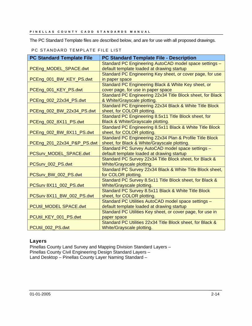
The PC Standard Template files are described below, and are for use with all proposed drawings.
P C S T A N D A R D T E M P L A T E F I L E L I S T
PC Standard Template File PC Standard Template File - Description
PCEng_MODEL_SPACE.dwt Standard PC Engineering AutoCAD model space settings – default template loaded at drawing startup
PCEng_001_BW_KEY_PS.dwt Standard PC Engineering Key sheet, or cover page, for use in paper space
PCEng_001_KEY_PS.dwt Standard PC Engineering Black & White Key sheet, or cover page, for use in paper space
PCEng_002_22x34_PS.dwt Standard PC Engineering 22x34 Title Block sheet, for Black & White/Grayscale plotting.
PCEng_002_BW_22x34_PS.dwt Standard PC Engineering 22x34 Black & White Title Block sheet, for COLOR plotting.
PCEng_002_8X11_PS.dwt Standard PC Engineering 8.5x11 Title Block sheet, for Black & White/Grayscale plotting.
PCEng_002_BW_8X11_PS.dwt Standard PC Engineering 8.5x11 Black & White Title Block sheet, for COLOR plotting.
PCEng_201_22x34_P&P_PS.dwt Standard PC Engineering 22x34 Plan & Profile Title Block sheet, for Black & White/Grayscale plotting.
PCSurv_MODEL_SPACE.dwt Standard PC Survey AutoCAD model space settings – default template loaded at drawing startup
PCSurv_002_PS.dwt Standard PC Survey 22x34 Title Block sheet, for Black & White/Grayscale plotting.
PCSurv_BW_002_PS.dwt Standard PC Survey 22x34 Black & White Title Block sheet, for COLOR plotting.
PCSurv 8X11_002_PS.dwt Standard PC Survey 8.5x11 Title Block sheet, for Black & White/Grayscale plotting.
PCSurv 8X11_BW_002_PS.dwt Standard PC Survey 8.5x11 Black & White Title Block sheet, for COLOR plotting.
PCUtil_MODEL SPACE.dwt Standard PC Utilities AutoCAD model space settings – default template loaded at drawing startup
PCUtil_KEY_001_PS.dwt Standard PC Utilities Key sheet, or cover page, for use in paper space
PCUtil_002_PS.dwt Standard PC Utilities 22x34 Title Block sheet, for Black & White/Grayscale plotting.
Layers Pinellas County Land Survey and Mapping Division Standard Layers – Pinellas County Civil Engineering Design Standard Layers – Land Desktop – Pinellas County Layer Naming Standard –
P I N E L L A S C O U N T Y C A D D S T A N D A R D S M A N U A L
01-01-2005 2-15
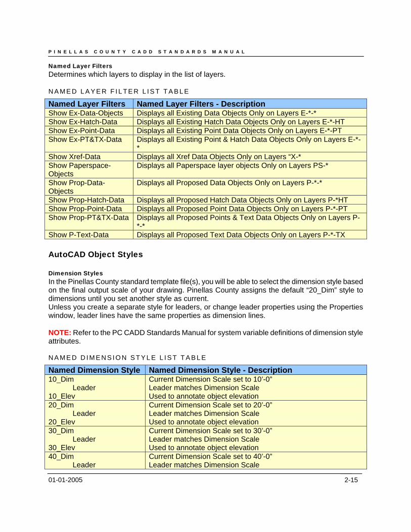
Named Layer Filters Determines which layers to display in the list of layers. N A M E D L A Y E R F I L T E R L I S T T A B L E
Named Layer Filters Named Layer Filters - Description Show Ex-Data-Objects Displays all Existing Data Objects Only on Layers E-*-* Show Ex-Hatch-Data Displays all Existing Hatch Data Objects Only on Layers E-*-HT Show Ex-Point-Data Displays all Existing Point Data Objects Only on Layers E-*-PT Show Ex-PT&TX-Data Displays all Existing Point & Hatch Data Objects Only on Layers E-*-
* Show Xref-Data Displays all Xref Data Objects Only on Layers “X-* Show Paperspace-Objects
Displays all Paperspace layer objects Only on Layers PS-*
Show Prop-Data-Objects
Displays all Proposed Data Objects Only on Layers P-*-*
Show Prop-Hatch-Data Displays all Proposed Hatch Data Objects Only on Layers P-*HT Show Prop-Point-Data Displays all Proposed Point Data Objects Only on Layers P-*-PT Show Prop-PT&TX-Data Displays all Proposed Points & Text Data Objects Only on Layers P-
*-* Show P-Text-Data Displays all Proposed Text Data Objects Only on Layers P-*-TX AutoCAD Object Styles Dimension Styles In the Pinellas County standard template file(s), you will be able to select the dimension style based on the final output scale of your drawing. Pinellas County assigns the default “20_Dim” style to dimensions until you set another style as current. Unless you create a separate style for leaders, or change leader properties using the Properties window, leader lines have the same properties as dimension lines. NOTE: Refer to the PC CADD Standards Manual for system variable definitions of dimension style attributes. N A M E D D I M E N S I O N S T Y L E L I S T T A B L E
Named Dimension Style Named Dimension Style - Description 10_Dim
Leader 10_Elev
Current Dimension Scale set to 10’-0” Leader matches Dimension Scale Used to annotate object elevation
20_Dim Leader
20_Elev
Current Dimension Scale set to 20’-0” Leader matches Dimension Scale Used to annotate object elevation
30_Dim Leader
30_Elev
Current Dimension Scale set to 30’-0” Leader matches Dimension Scale Used to annotate object elevation
40_Dim Leader
Current Dimension Scale set to 40’-0” Leader matches Dimension Scale
P I N E L L A S C O U N T Y C A D D S T A N D A R D S M A N U A L
01-01-2005 2-16
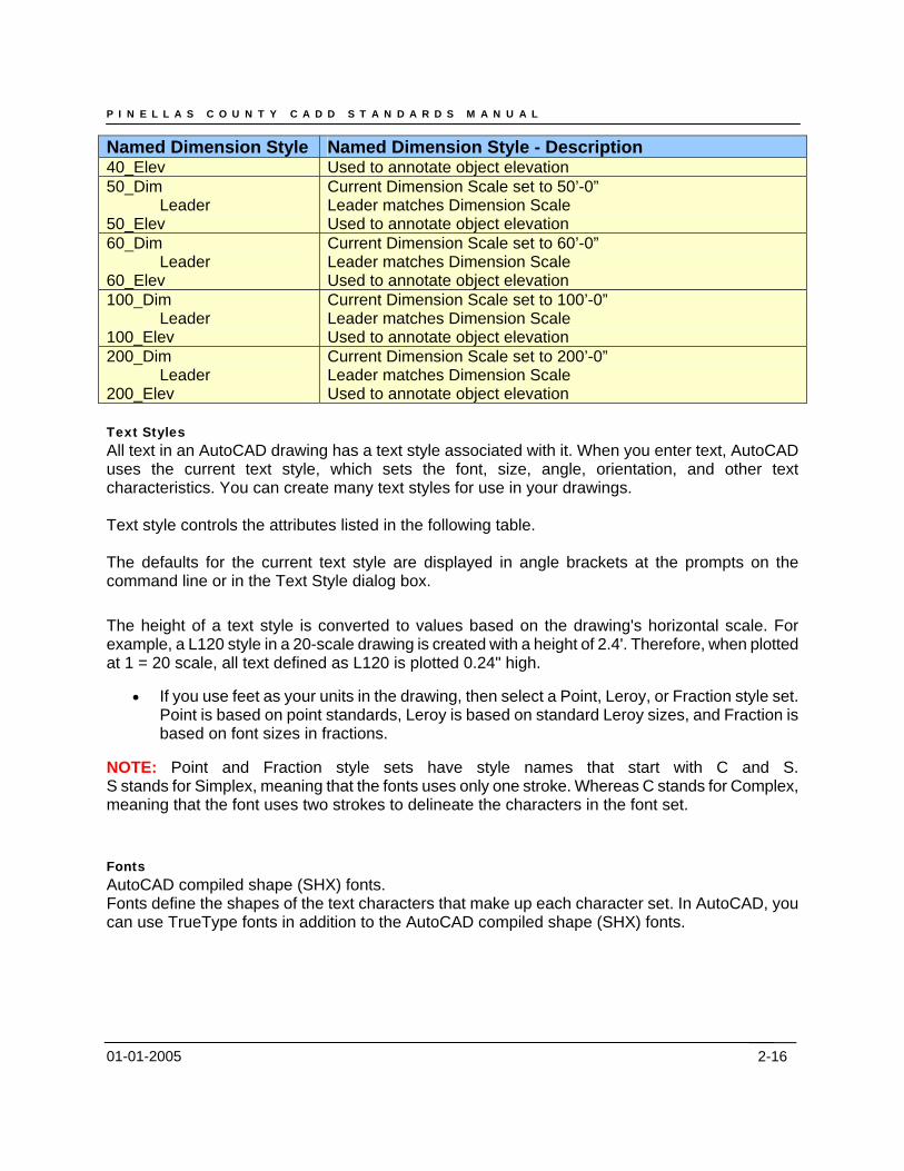
Named Dimension Style Named Dimension Style - Description 40_Elev Used to annotate object elevation 50_Dim
Leader 50_Elev
Current Dimension Scale set to 50’-0” Leader matches Dimension Scale Used to annotate object elevation
60_Dim Leader
60_Elev
Current Dimension Scale set to 60’-0” Leader matches Dimension Scale Used to annotate object elevation
100_Dim Leader
100_Elev
Current Dimension Scale set to 100’-0” Leader matches Dimension Scale Used to annotate object elevation
200_Dim Leader
200_Elev
Current Dimension Scale set to 200’-0” Leader matches Dimension Scale Used to annotate object elevation
Text Styles All text in an AutoCAD drawing has a text style associated with it. When you enter text, AutoCAD uses the current text style, which sets the font, size, angle, orientation, and other text characteristics. You can create many text styles for use in your drawings. Text style controls the attributes listed in the following table. The defaults for the current text style are displayed in angle brackets at the prompts on the command line or in the Text Style dialog box. The height of a text style is converted to values based on the drawing's horizontal scale. For example, a L120 style in a 20-scale drawing is created with a height of 2.4'. Therefore, when plotted at 1 = 20 scale, all text defined as L120 is plotted 0.24" high.
• If you use feet as your units in the drawing, then select a Point, Leroy, or Fraction style set. Point is based on point standards, Leroy is based on standard Leroy sizes, and Fraction is based on font sizes in fractions.
NOTE: Point and Fraction style sets have style names that start with C and S. S stands for Simplex, meaning that the fonts uses only one stroke. Whereas C stands for Complex, meaning that the font uses two strokes to delineate the characters in the font set.
Fonts AutoCAD compiled shape (SHX) fonts. Fonts define the shapes of the text characters that make up each character set. In AutoCAD, you can use TrueType fonts in addition to the AutoCAD compiled shape (SHX) fonts.
P I N E L L A S C O U N T Y C A D D S T A N D A R D S M A N U A L
01-01-2005 2-17
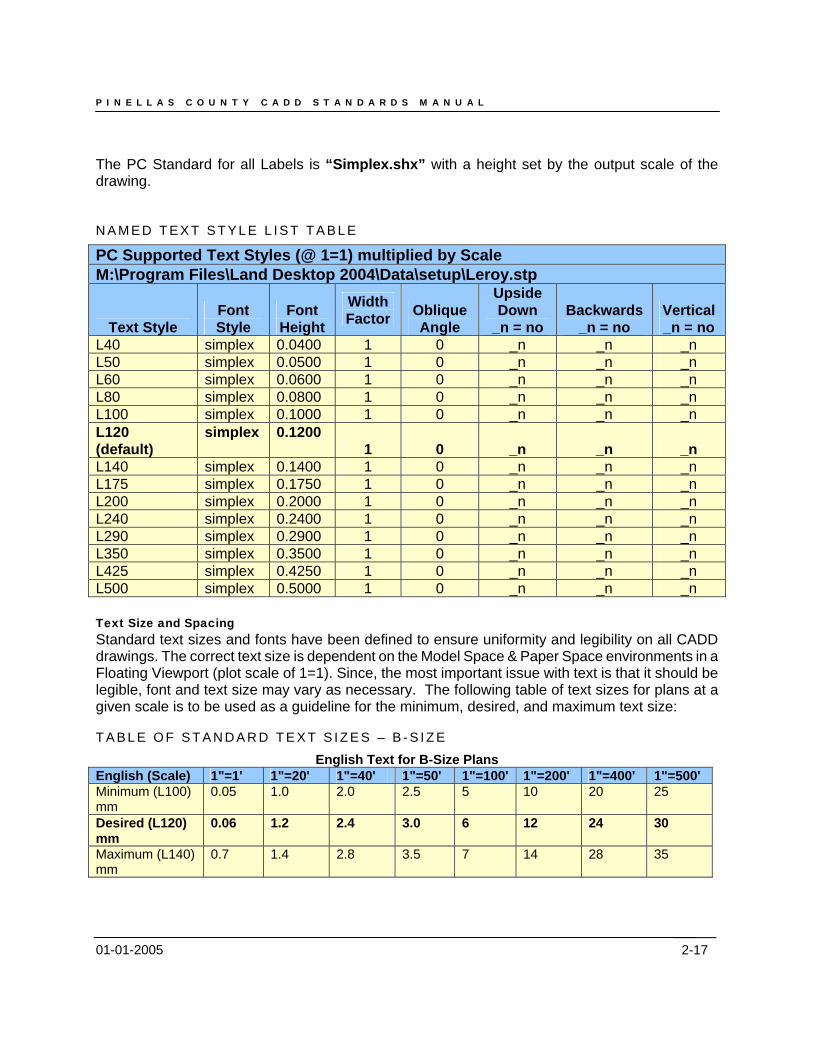
The PC Standard for all Labels is “Simplex.shx” with a height set by the output scale of the drawing. N A M E D T E X T S T Y L E L I S T T A B L E
PC Supported Text Styles (@ 1=1) multiplied by Scale M:\Program Files\Land Desktop 2004\Data\setup\Leroy.stp
Text Style Font Style
Font Height
Width Factor Oblique
Angle
Upside Down
_n = no Backwards
_n = no Vertical _n = no
L40 simplex 0.0400 1 0 _n _n _n L50 simplex 0.0500 1 0 _n _n _n L60 simplex 0.0600 1 0 _n _n _n L80 simplex 0.0800 1 0 _n _n _n L100 simplex 0.1000 1 0 _n _n _n L120 (default)
simplex 0.1200 1 0 _n _n _n
L140 simplex 0.1400 1 0 _n _n _n L175 simplex 0.1750 1 0 _n _n _n L200 simplex 0.2000 1 0 _n _n _n L240 simplex 0.2400 1 0 _n _n _n L290 simplex 0.2900 1 0 _n _n _n L350 simplex 0.3500 1 0 _n _n _n L425 simplex 0.4250 1 0 _n _n _n L500 simplex 0.5000 1 0 _n _n _n Text Size and Spacing Standard text sizes and fonts have been defined to ensure uniformity and legibility on all CADD drawings. The correct text size is dependent on the Model Space & Paper Space environments in a Floating Viewport (plot scale of 1=1). Since, the most important issue with text is that it should be legible, font and text size may vary as necessary. The following table of text sizes for plans at a given scale is to be used as a guideline for the minimum, desired, and maximum text size: T A B L E O F S T A N D A R D T E X T S I Z E S – B - S I Z E
English Text for B-Size Plans English (Scale) 1"=1' 1"=20' 1"=40' 1"=50' 1"=100' 1"=200' 1"=400' 1"=500' Minimum (L100) mm
0.05 1.0 2.0 2.5 5 10 20 25
Desired (L120) mm
0.06 1.2 2.4 3.0 6 12 24 30
Maximum (L140) mm
0.7 1.4 2.8 3.5 7 14 28 35
P I N E L L A S C O U N T Y C A D D S T A N D A R D S M A N U A L
01-01-2005 2-18
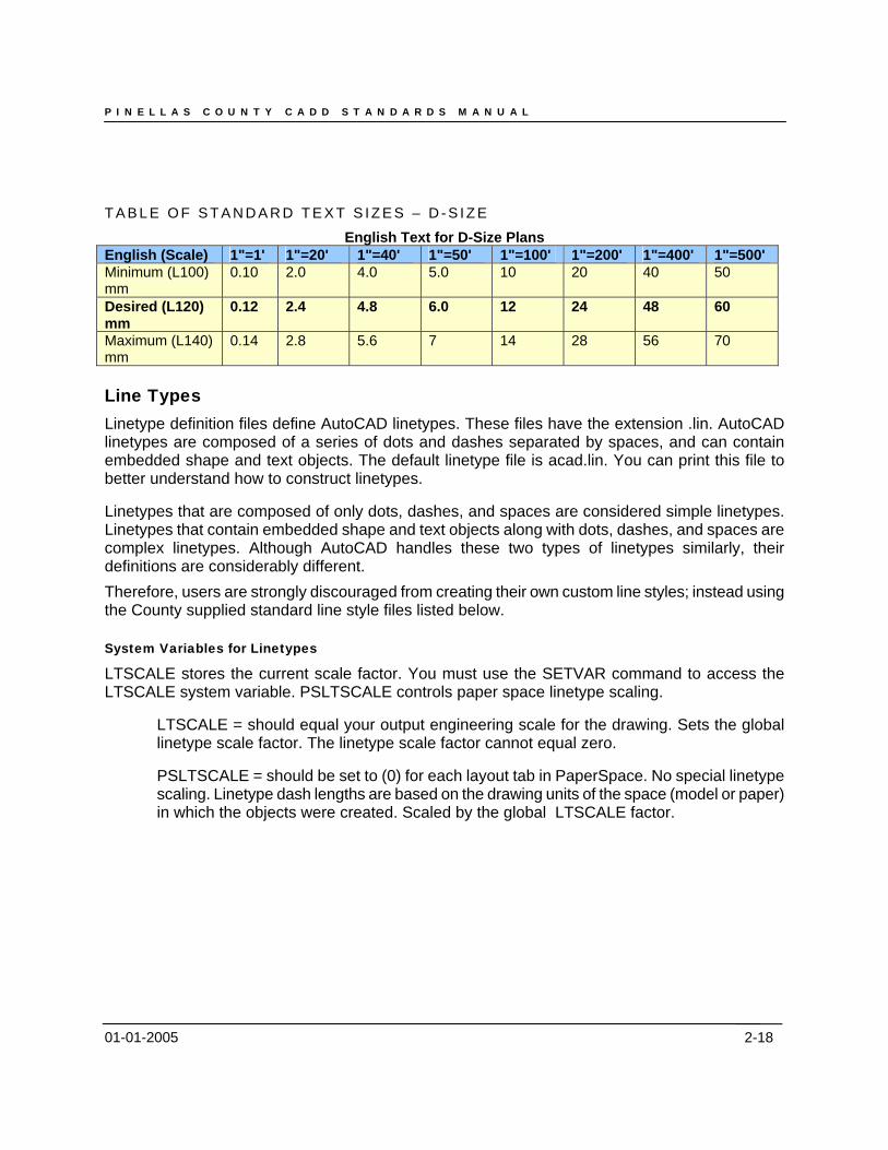
T A B L E O F S T A N D A R D T E X T S I Z E S – D - S I Z E
English Text for D-Size Plans English (Scale) 1"=1' 1"=20' 1"=40' 1"=50' 1"=100' 1"=200' 1"=400' 1"=500' Minimum (L100) mm
0.10 2.0 4.0 5.0 10 20 40 50
Desired (L120) mm
0.12 2.4 4.8 6.0 12 24 48 60
Maximum (L140) mm
0.14 2.8 5.6 7 14 28 56 70
Line Types Linetype definition files define AutoCAD linetypes. These files have the extension .lin. AutoCAD linetypes are composed of a series of dots and dashes separated by spaces, and can contain embedded shape and text objects. The default linetype file is acad.lin. You can print this file to better understand how to construct linetypes.
Linetypes that are composed of only dots, dashes, and spaces are considered simple linetypes. Linetypes that contain embedded shape and text objects along with dots, dashes, and spaces are complex linetypes. Although AutoCAD handles these two types of linetypes similarly, their definitions are considerably different. Therefore, users are strongly discouraged from creating their own custom line styles; instead using the County supplied standard line style files listed below. System Variables for Linetypes
LTSCALE stores the current scale factor. You must use the SETVAR command to access the LTSCALE system variable. PSLTSCALE controls paper space linetype scaling.
LTSCALE = should equal your output engineering scale for the drawing. Sets the global linetype scale factor. The linetype scale factor cannot equal zero.
PSLTSCALE = should be set to (0) for each layout tab in PaperSpace. No special linetype scaling. Linetype dash lengths are based on the drawing units of the space (model or paper) in which the objects were created. Scaled by the global LTSCALE factor.
P I N E L L A S C O U N T Y C A D D S T A N D A R D S M A N U A L
01-01-2005
PC Custom Line Type Files
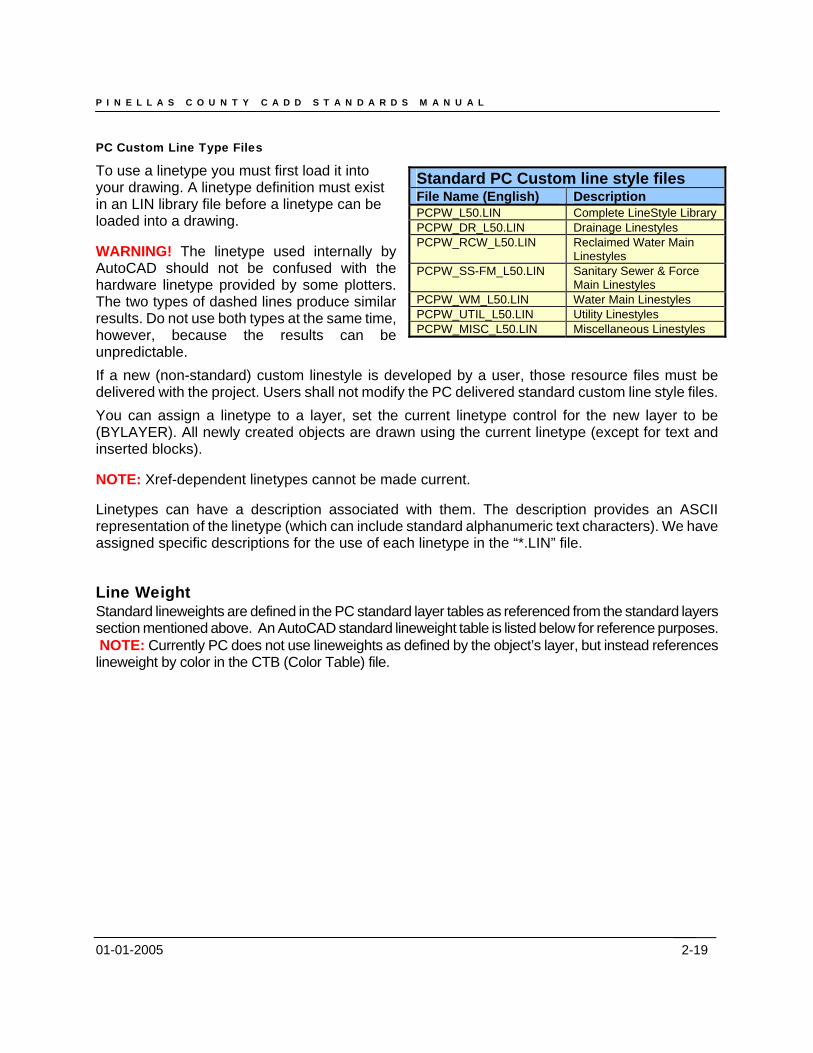
To use a linetype you must first load it into your drawing. A linetype definition must exist in an LIN library file before a linetype can be loaded into a drawing.
Standard PC Custom line style files File Name (English) Description PCPW_L50.LIN Complete LineStyle Library PCPW_DR_L50.LIN Drainage Linestyles PCPW_RCW_L50.LIN Reclaimed Water Main
Linestyles PCPW_SS-FM_L50.LIN Sanitary Sewer & Force
Main Linestyles PCPW_WM_L50.LIN Water Main Linestyles PCPW_UTIL_L50.LIN Utility Linestyles PCPW_MISC_L50.LIN Miscellaneous Linestyles
WARNING! The linetype used internally by AutoCAD should not be confused with the hardware linetype provided by some plotters. The two types of dashed lines produce similar results. Do not use both types at the same time, however, because the results can be unpredictable. If a new (non-standard) custom linestyle is developed by a user, those resource files must be delivered with the project. Users shall not modify the PC delivered standard custom line style files. You can assign a linetype to a layer, set the current linetype control for the new layer to be (BYLAYER). All newly created objects are drawn using the current linetype (except for text and inserted blocks).
NOTE: Xref-dependent linetypes cannot be made current.
Linetypes can have a description associated with them. The description provides an ASCII representation of the linetype (which can include standard alphanumeric text characters). We have assigned specific descriptions for the use of each linetype in the “*.LIN” file.
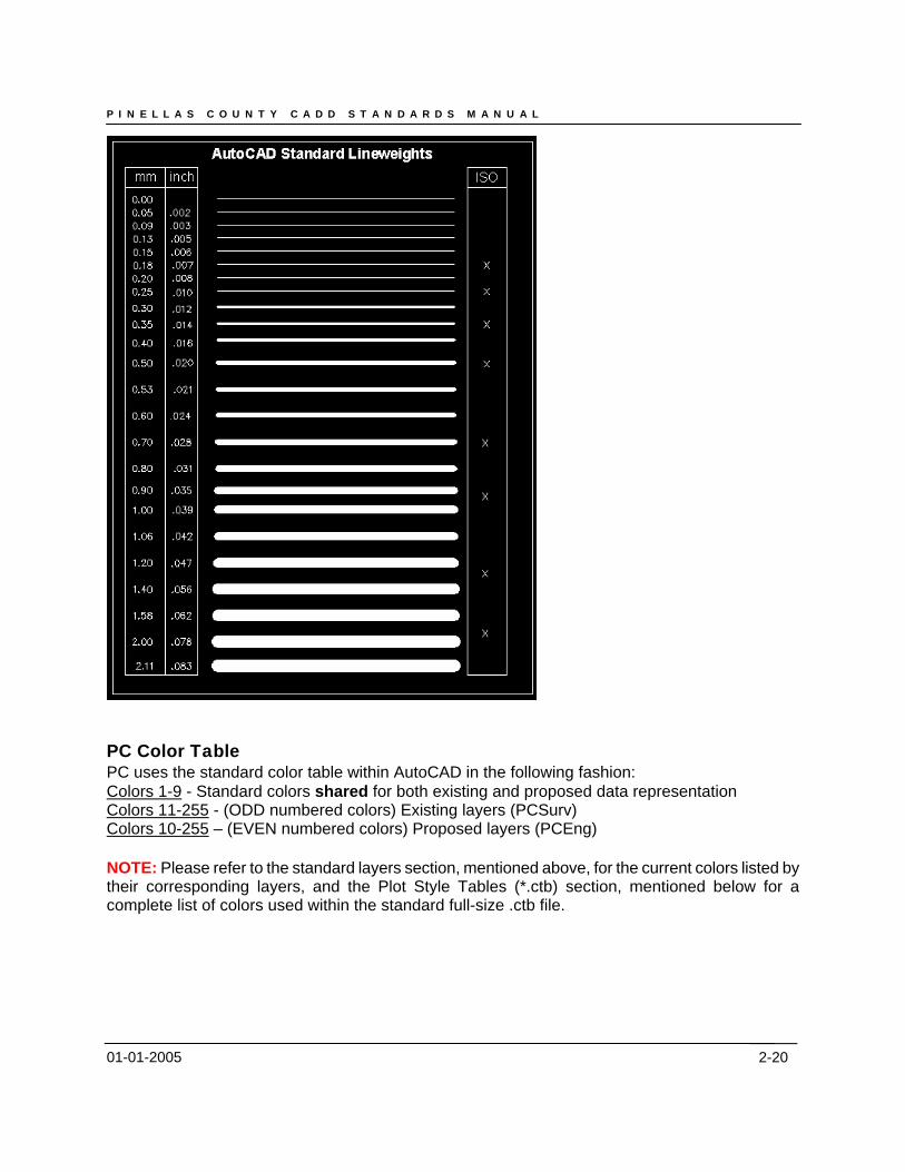
Line Weight Standard lineweights are defined in the PC standard layer tables as referenced from the standard layers section mentioned above. An AutoCAD standard lineweight table is listed below for reference purposes. NOTE: Currently PC does not use lineweights as defined by the object’s layer, but instead references lineweight by color in the CTB (Color Table) file.
2-19
P I N E L L A S C O U N T Y C A D D S T A N D A R D S M A N U A L
01-01-2005
PC Color Table PC uses the standard color table within AutoCAD in the following fashion: Colors 1-9 - Standard colors shared for both existing and proposed data representation Colors 11-255 - (ODD numbered colors) Existing layers (PCSurv) Colors 10-255 – (EVEN numbered colors) Proposed layers (PCEng) NOTE: Please refer to the standard layers section, mentioned above, for the current colors listed by their corresponding layers, and the Plot Style Tables (*.ctb) section, mentioned below for a complete list of colors used within the standard full-size .ctb file.
2-20
P I N E L L A S C O U N T Y C A D D S T A N D A R D S M A N U A L
01-01-2005 2-21
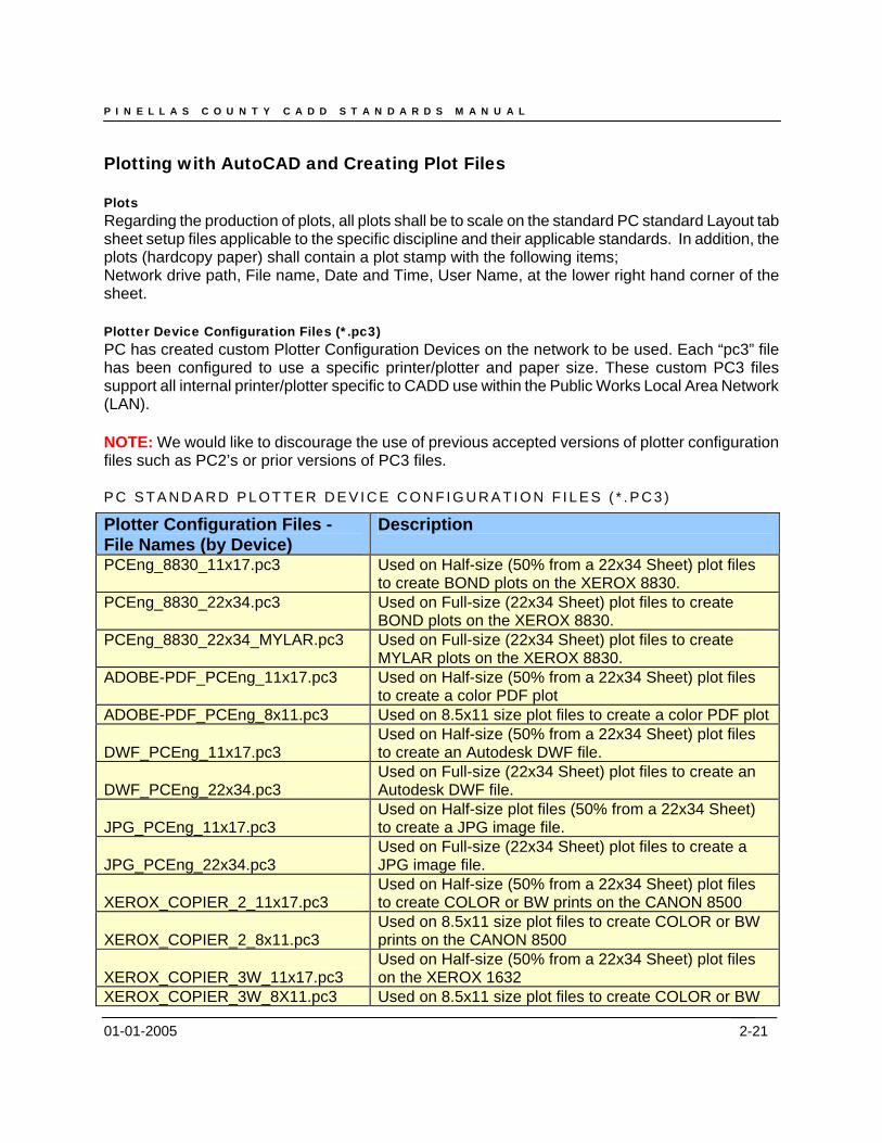
Plotting with AutoCAD and Creating Plot Files Plots Regarding the production of plots, all plots shall be to scale on the standard PC standard Layout tab sheet setup files applicable to the specific discipline and their applicable standards. In addition, the plots (hardcopy paper) shall contain a plot stamp with the following items; Network drive path, File name, Date and Time, User Name, at the lower right hand corner of the sheet. Plotter Device Configuration Files (*.pc3) PC has created custom Plotter Configuration Devices on the network to be used. Each “pc3” file has been configured to use a specific printer/plotter and paper size. These custom PC3 files support all internal printer/plotter specific to CADD use within the Public Works Local Area Network (LAN). NOTE: We would like to discourage the use of previous accepted versions of plotter configuration files such as PC2’s or prior versions of PC3 files. P C S T A N D A R D P L O T T E R D E V I C E C O N F I G U R A T I O N F I L E S ( * . P C 3 )
Plotter Configuration Files - File Names (by Device)
Description
PCEng_8830_11x17.pc3 Used on Half-size (50% from a 22x34 Sheet) plot files to create BOND plots on the XEROX 8830.
PCEng_8830_22x34.pc3 Used on Full-size (22x34 Sheet) plot files to create BOND plots on the XEROX 8830.
PCEng_8830_22x34_MYLAR.pc3 Used on Full-size (22x34 Sheet) plot files to create MYLAR plots on the XEROX 8830.
ADOBE-PDF_PCEng_11x17.pc3 Used on Half-size (50% from a 22x34 Sheet) plot files to create a color PDF plot
ADOBE-PDF_PCEng_8x11.pc3 Used on 8.5x11 size plot files to create a color PDF plot
DWF_PCEng_11x17.pc3 Used on Half-size (50% from a 22x34 Sheet) plot files to create an Autodesk DWF file.
DWF_PCEng_22x34.pc3 Used on Full-size (22x34 Sheet) plot files to create an Autodesk DWF file.
JPG_PCEng_11x17.pc3 Used on Half-size plot files (50% from a 22x34 Sheet) to create a JPG image file.
JPG_PCEng_22x34.pc3 Used on Full-size (22x34 Sheet) plot files to create a JPG image file.
XEROX_COPIER_2_11x17.pc3 Used on Half-size (50% from a 22x34 Sheet) plot files to create COLOR or BW prints on the CANON 8500
XEROX_COPIER_2_8x11.pc3 Used on 8.5x11 size plot files to create COLOR or BW prints on the CANON 8500
XEROX_COPIER_3W_11x17.pc3 Used on Half-size (50% from a 22x34 Sheet) plot files on the XEROX 1632
XEROX_COPIER_3W_8X11.pc3 Used on 8.5x11 size plot files to create COLOR or BW
P I N E L L A S C O U N T Y C A D D S T A N D A R D S M A N U A L
01-01-2005 2-22
Plotter Configuration Files - File Names (by Device)
Description
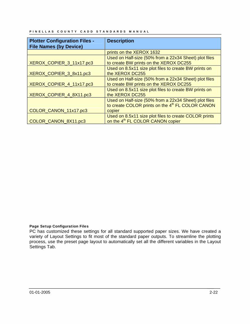
prints on the XEROX 1632
XEROX_COPIER_3_11x17.pc3 Used on Half-size (50% from a 22x34 Sheet) plot files to create BW prints on the XEROX DC255
XEROX_COPIER_3_8x11.pc3 Used on 8.5x11 size plot files to create BW prints on the XEROX DC255
XEROX_COPIER_4_11x17.pc3 Used on Half-size (50% from a 22x34 Sheet) plot files to create BW prints on the XEROX DC255
XEROX_COPIER_4_8X11.pc3 Used on 8.5x11 size plot files to create BW prints on the XEROX DC255
COLOR_CANON_11x17.pc3
Used on Half-size (50% from a 22x34 Sheet) plot files to create COLOR prints on the 4th FL COLOR CANON copier
COLOR_CANON_8X11.pc3 Used on 8.5x11 size plot files to create COLOR prints on the 4th FL COLOR CANON copier
Page Setup Configuration Files PC has customized these settings for all standard supported paper sizes. We have created a variety of Layout Settings to fit most of the standard paper outputs. To streamline the plotting process, use the preset page layout to automatically set all the different variables in the Layout Settings Tab.
P I N E L L A S C O U N T Y C A D D S T A N D A R D S M A N U A L
01-01-2005
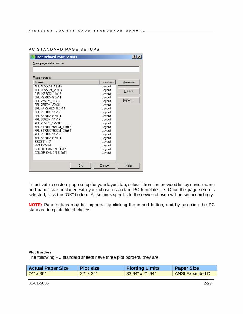
P C S T A N D A R D P A G E S E T U P S
To activate a custom page setup for your layout tab, select it from the provided list by device name and paper size, included with your chosen standard PC template file. Once the page setup is selected, click the “OK” button. All settings specific to the device chosen will be set accordingly. NOTE: Page setups may be imported by clicking the import button, and by selecting the PC standard template file of choice. Plot Borders The following PC standard sheets have three plot borders, they are: Actual Paper Size Plot size Plotting Limits Paper Size 24” x 36” 22” x 34” 33.94” x 21.94” ANSI Expanded D
2-23
P I N E L L A S C O U N T Y C A D D S T A N D A R D S M A N U A L
01-01-2005 2-24
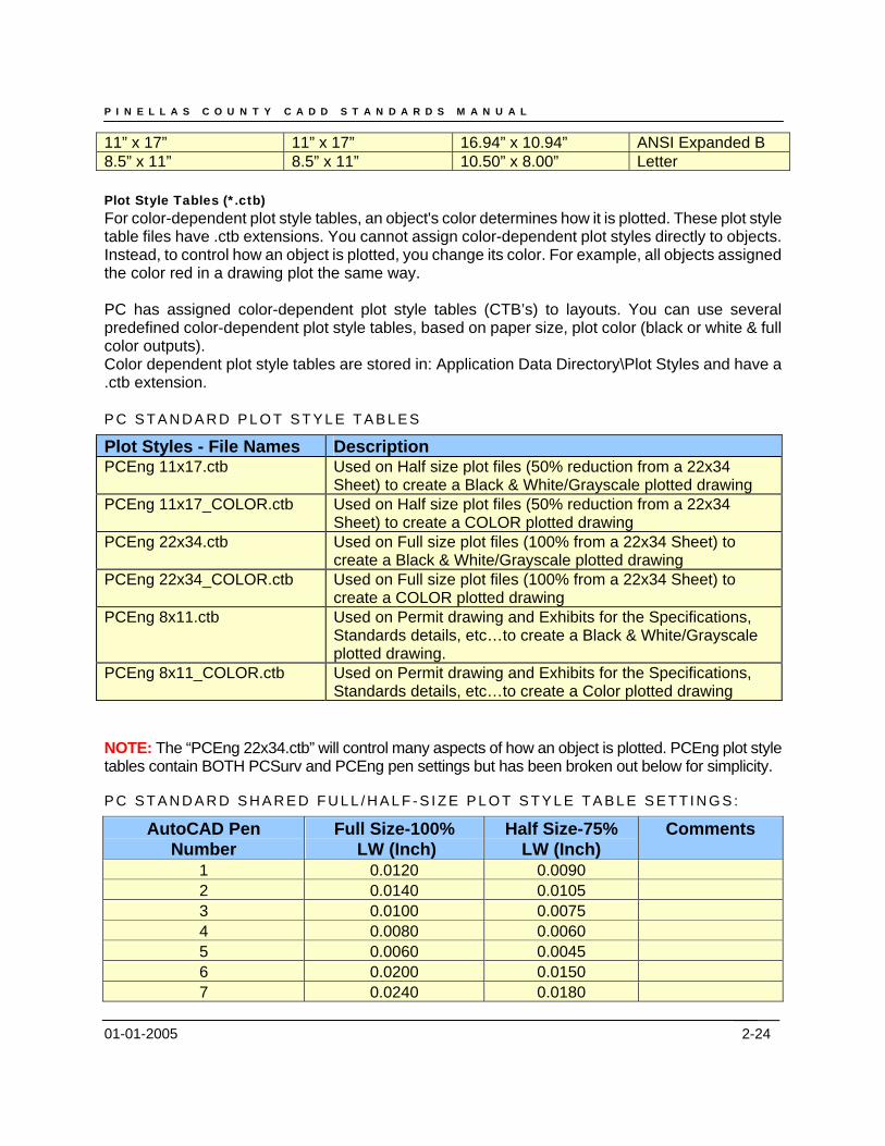
11” x 17” 11” x 17” 16.94” x 10.94” ANSI Expanded B 8.5” x 11” 8.5” x 11” 10.50” x 8.00” Letter Plot Style Tables (*.ctb) For color-dependent plot style tables, an object's color determines how it is plotted. These plot style table files have .ctb extensions. You cannot assign color-dependent plot styles directly to objects. Instead, to control how an object is plotted, you change its color. For example, all objects assigned the color red in a drawing plot the same way. PC has assigned color-dependent plot style tables (CTB’s) to layouts. You can use several predefined color-dependent plot style tables, based on paper size, plot color (black or white & full color outputs). Color dependent plot style tables are stored in: Application Data Directory\Plot Styles and have a .ctb extension. P C S T A N D A R D P L O T S T Y L E T A B L E S
Plot Styles - File Names Description PCEng 11x17.ctb Used on Half size plot files (50% reduction from a 22x34
Sheet) to create a Black & White/Grayscale plotted drawing PCEng 11x17_COLOR.ctb Used on Half size plot files (50% reduction from a 22x34
Sheet) to create a COLOR plotted drawing PCEng 22x34.ctb Used on Full size plot files (100% from a 22x34 Sheet) to
create a Black & White/Grayscale plotted drawing PCEng 22x34_COLOR.ctb Used on Full size plot files (100% from a 22x34 Sheet) to
create a COLOR plotted drawing PCEng 8x11.ctb Used on Permit drawing and Exhibits for the Specifications,
Standards details, etc…to create a Black & White/Grayscale plotted drawing.
PCEng 8x11_COLOR.ctb Used on Permit drawing and Exhibits for the Specifications, Standards details, etc…to create a Color plotted drawing
NOTE: The “PCEng 22x34.ctb” will control many aspects of how an object is plotted. PCEng plot style tables contain BOTH PCSurv and PCEng pen settings but has been broken out below for simplicity.
P C S T A N D A R D S H A R E D F U L L / H A L F - S I Z E P L O T S T Y L E T A B L E S E T T I N G S :
AutoCAD Pen Number
Full Size-100% LW (Inch)
Half Size-75% LW (Inch)
Comments
1 0.0120 0.0090 2 0.0140 0.0105 3 0.0100 0.0075 4 0.0080 0.0060 5 0.0060 0.0045 6 0.0200 0.0150 7 0.0240 0.0180

P I N E L L A S C O U N T Y C A D D S T A N D A R D S M A N U A L
01-01-2005 2-25
AutoCAD Pen Number
Full Size-100% LW (Inch)
Half Size-75% LW (Inch)
Comments
8 0.0100 0.0075 9 0.0240 0.0180
P C E N G S T A N D A R D F U L L / H A L F - S I Z E P L O T S T Y L E T A B L E S E T T I N G S :
AutoCAD Pen Number
Full Size-100% LW (Inch)
Half Size-75% LW (Inch)
Comments
10 0.0240 0.0180 12 0.0200 0.0150 14 0.0200 0.0150
16 & 18 0.0100 0.0075 20 0.0240 0.0180
22-30 0.0100 0.0075 32 0.0080 0.0060
34-40 0.0100 0.0075 42 0.0160 0.0120 44 0.0100 0.0075 46 0.0200 0.0150 48 0.0100 0.0075 50 0.0200 0.0150 52 0.0140 0.0105 54 0.0120 0.0090
56-78 0.0100 0.0075 80 0.0140 0.0105
82-88 0.0100 0.0075 90 0.0200 0.0150 92 0.0100 0.0075 94 0.0200 0.0150
96 & 98 0.0100 0.0075 100 0.0140 0.0105 102 0.0140 0.0105 104 0.0140 0.0105
106 - 118 0.0100 0.0075 120 0.0160 0.0120
122 - 128 0.0100 0.0075 130 0.0200 0.0150 132 0.0200 0.0150 134 0.0200 0.0150
136 & 138 0.0100 0.0075 140 0.0200 0.0150
142 - 152 0.0100 0.0075
P I N E L L A S C O U N T Y C A D D S T A N D A R D S M A N U A L
01-01-2005 2-26
AutoCAD Pen Number
Full Size-100% LW (Inch)
Half Size-75% LW (Inch)
Comments
154 0.0240 0.0180 156 - 198 0.0100 0.0075
200 0.0200 0.0150 202 - 208 0.0100 0.0075
210 0.0240 0.0180 212 - 218 0.0100 0.0075
220 0.0200 0.0150 222 - 238 0.0100 0.0075
240 0.0200 0.0150 242 - 250 0.0100 0.0075
252 0.0140 0.0105 254 0.0140 0.0105
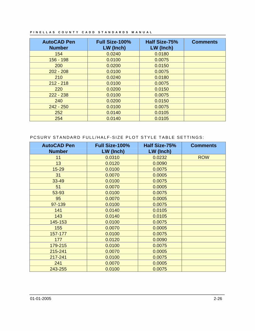
P C S U R V S T A N D A R D F U L L / H A L F - S I Z E P L O T S T Y L E T A B L E S E T T I N G S :
AutoCAD Pen Number
Full Size-100% LW (Inch)
Half Size-75% LW (Inch)
Comments
11 0.0310 0.0232 ROW 13 0.0120 0.0090
15-29 0.0100 0.0075 31 0.0070 0.0005
33-49 0.0100 0.0075 51 0.0070 0.0005
53-93 0.0100 0.0075 95 0.0070 0.0005
97-139 0.0100 0.0075 141 0.0140 0.0105 143 0.0140 0.0105
145-153 0.0100 0.0075 155 0.0070 0.0005
157-177 0.0100 0.0075 177 0.0120 0.0090
179-215 0.0100 0.0075 215-241 0.0070 0.0005 217-241 0.0100 0.0075
241 0.0070 0.0005 243-255 0.0100 0.0075
P I N E L L A S C O U N T Y C A D D S T A N D A R D S M A N U A L
01-01-2005 2-27
Plotting to a Plot File (*.plt) Plot to file setting is used to capture a plan image for plotting at a milestone in the project or to run a complete set of plots to the printer overnight. Plot files for projects milestone shall be saved in the following folder and follow the plot file naming conventions outline in Chapter 6, File Names for AutoCAD (Plot) files by Contract Plan Set Disciplines.
Plotting to a PDF File (*.pdf)
You can use the non-system PostScript driver to plot drawings to PostScript printers and PostScript files. Use the PS file format for printers and the EPS file format for files. If you plot to a hardware port, PS output is automatic. If you plot to a file and plan to copy the file to a printer, configure for PS output.
Use the custom Properties dialog box in the Plotter Configuration Editor to customize the output. To display this dialog box, on the Device and Document Settings tab, in the tree view, select Custom Properties. Then under Access Custom Dialog, choose the Custom Properties button.
The PostScript driver supports three types of PostScript.
Level 1: Use for most plotters.
Level 1.5: Use for plotters that support color images.
Level 2: If your plotter supports Level 2 PostScript, use to produce smaller files that print more rapidly.
10/30/2007 2-28
Chapter 3
Land Desktop Standards (LDT)
10/30/2007 2-29
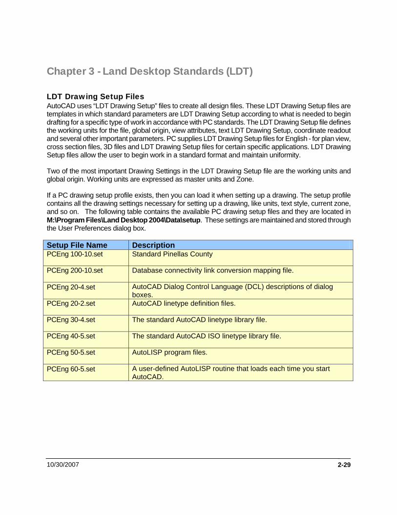
Chapter 3 - Land Desktop Standards (LDT) LDT Drawing Setup Files AutoCAD uses “LDT Drawing Setup” files to create all design files. These LDT Drawing Setup files are templates in which standard parameters are LDT Drawing Setup according to what is needed to begin drafting for a specific type of work in accordance with PC standards. The LDT Drawing Setup file defines the working units for the file, global origin, view attributes, text LDT Drawing Setup, coordinate readout and several other important parameters. PC supplies LDT Drawing Setup files for English - for plan view, cross section files, 3D files and LDT Drawing Setup files for certain specific applications. LDT Drawing Setup files allow the user to begin work in a standard format and maintain uniformity.
Two of the most important Drawing Settings in the LDT Drawing Setup file are the working units and global origin. Working units are expressed as master units and Zone.
If a PC drawing setup profile exists, then you can load it when setting up a drawing. The setup profile contains all the drawing settings necessary for setting up a drawing, like units, text style, current zone, and so on. The following table contains the available PC drawing setup files and they are located in M:\Program Files\Land Desktop 2004\Data\setup. These settings are maintained and stored through the User Preferences dialog box.
Setup File Name Description PCEng 100-10.set Standard Pinellas County
PCEng 200-10.set Database connectivity link conversion mapping file.
PCEng 20-4.set AutoCAD Dialog Control Language (DCL) descriptions of dialog boxes.
PCEng 20-2.set AutoCAD linetype definition files.
PCEng 30-4.set The standard AutoCAD linetype library file.
PCEng 40-5.set The standard AutoCAD ISO linetype library file.
PCEng 50-5.set AutoLISP program files.
PCEng 60-5.set A user-defined AutoLISP routine that loads each time you start AutoCAD.
P I N E L L A S C O U N T Y C A D D S T A N D A R D S M A N U A L
10/30/07 2-30
User Preferences Support Paths: The User Preferences control program-wide preferences such as the project paths for various files, the AutoCAD overrides, and the drawing setup method. All of the LDT user preferences paths are controlled via the sdsk.dfm file to be in compliance with PC CADD Standards, including LDT setup files.
The file paths include paths for storing prototypes, speed tables, and drawing setup profiles. The AutoCAD overrides include options you can select to use the non-project based version of AutoCAD New and Open commands and to control whether the Start Up dialog box is displayed at the beginning of an Autodesk Land Desktop session.
The paths modified by the PCEng Standards set include the following:

P I N E L L A S C O U N T Y C A D D S T A N D A R D S M A N U A L
10/30/07 2-31
Shapes, Fonts and Linetypes LIN (linetype definition file) SHP (shape file) SHX (shape/font file) PSF (postscript support file) FMP (font mapping table) Other custom or output files CUS (custom dictionary) LAS (Last saved layer state) BLK (block attribute template file) BPL, BP2, BP3 (batch plot file: BPL, BP2 = R AutoCAD release 14 and earlier only, BP3 = AutoCAD 2000, 2000i, 2002) TXT (text file) CSV (comma separated text) LOG (Log file - also text) XLG (xref log file) DXX (DXF - style extracted attributes) SLD (slide file) SLB (slide library) DBQ (dbConnect query set) DBT (dbConnect template set) UDL (external database configuration files) LLI (landscape library) Plot related files PCP, PC2 (Plot configuration - AutoCAD Release 14 and earlier versions only) PC3 (Plot configuration - AutoCAD 2000 and later versions only) STB (Named Plot Style Table) CTB (Color-Dependant Plot Style Table) PLT (Plot-to-file format) EPS (plot-to-file format) PS (plot-to-file format)
P I N E L L A S C O U N T Y C A D D S T A N D A R D S M A N U A L
10/30/07 2-32
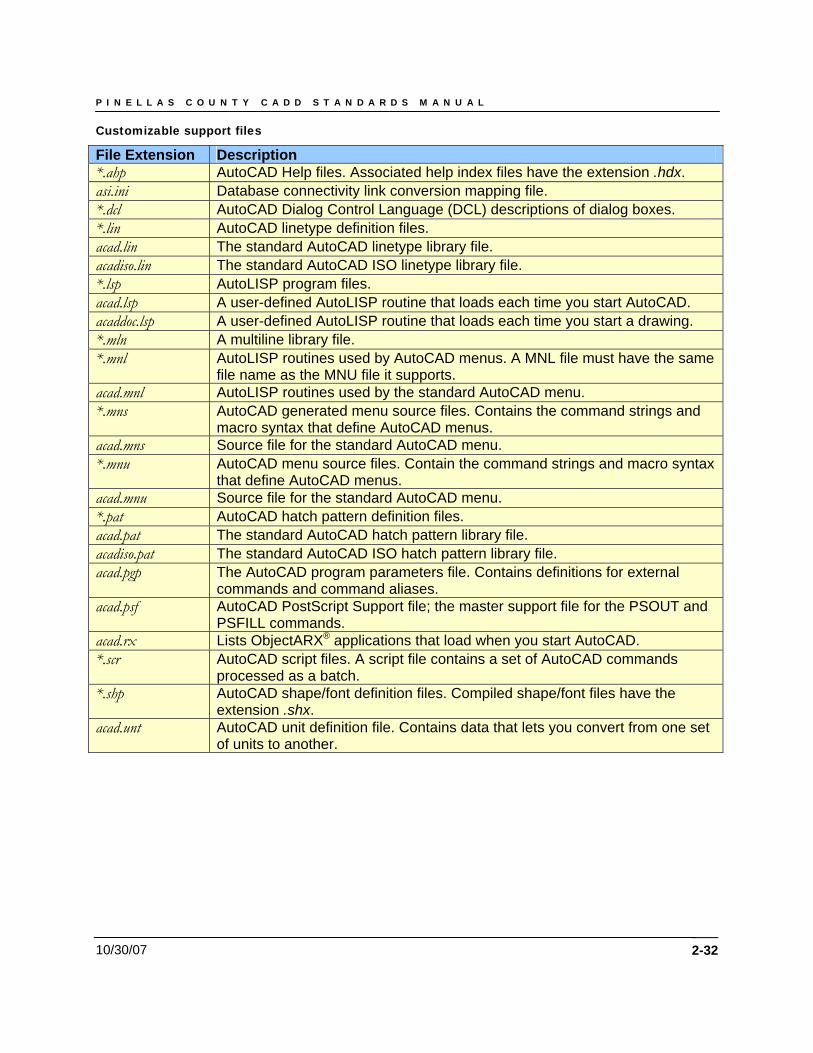
Customizable support files File Extension Description *.ahp AutoCAD Help files. Associated help index files have the extension .hdx. asi.ini Database connectivity link conversion mapping file. *.dcl AutoCAD Dialog Control Language (DCL) descriptions of dialog boxes. *.lin AutoCAD linetype definition files. acad.lin The standard AutoCAD linetype library file. acadiso.lin The standard AutoCAD ISO linetype library file. *.lsp AutoLISP program files. acad.lsp A user-defined AutoLISP routine that loads each time you start AutoCAD. acaddoc.lsp A user-defined AutoLISP routine that loads each time you start a drawing. *.mln A multiline library file. *.mnl AutoLISP routines used by AutoCAD menus. A MNL file must have the same
file name as the MNU file it supports. acad.mnl AutoLISP routines used by the standard AutoCAD menu. *.mns AutoCAD generated menu source files. Contains the command strings and
macro syntax that define AutoCAD menus. acad.mns Source file for the standard AutoCAD menu. *.mnu AutoCAD menu source files. Contain the command strings and macro syntax
that define AutoCAD menus. acad.mnu Source file for the standard AutoCAD menu. *.pat AutoCAD hatch pattern definition files. acad.pat The standard AutoCAD hatch pattern library file. acadiso.pat The standard AutoCAD ISO hatch pattern library file. acad.pgp The AutoCAD program parameters file. Contains definitions for external
commands and command aliases. acad.psf AutoCAD PostScript Support file; the master support file for the PSOUT and
PSFILL commands. acad.rx Lists ObjectARX® applications that load when you start AutoCAD. *.scr AutoCAD script files. A script file contains a set of AutoCAD commands
processed as a batch. *.shp AutoCAD shape/font definition files. Compiled shape/font files have the
extension .shx. acad.unt AutoCAD unit definition file. Contains data that lets you convert from one set
of units to another.
P I N E L L A S C O U N T Y C A D D S T A N D A R D S M A N U A L
10/30/07 2-33
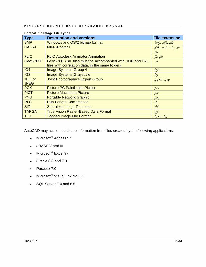
Compatible Image File Types Type Description and versions File extension BMP Windows and OS/2 bitmap format .bmp, .dib, .rle CALS-I Mil-R-Raster I .gp4, .mil, .rst, .cg4,
.cal FLIC FLIC Autodesk Animator Animation .flc, .fli GeoSPOT GeoSPOT (BIL files must be accompanied with HDR and PAL
files with correlation data, in the same folder) .bil
IG4 Image Systems Group 4 .ig4 IGS Image Systems Grayscale .igs JFIF or JPEG
Joint Photographics Expert Group .jpg or .jpeg
PCX Picture PC Paintbrush Picture .pcx PICT Picture Macintosh Picture .pct PNG Portable Network Graphic .png RLC Run-Length Compressed .rlc SID Seamless Image Database .sid TARGA True Vision Raster-Based Data Format .tga TIFF Tagged Image File Format .tif or .tiff
AutoCAD may access database information from files created by the following applications:
• Microsoft® Access 97
• dBASE V and III
• Microsoft® Excel 97
• Oracle 8.0 and 7.3
• Paradox 7.0
• Microsoft® Visual FoxPro 6.0
• SQL Server 7.0 and 6.5
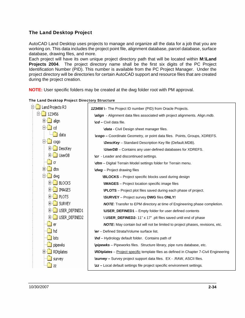
The Land Desktop Project AutoCAD Land Desktop uses projects to manage and organize all the data for a job that you are working on. This data includes the project point file, alignment database, parcel database, surface database, drawing files, and more. Each project will have its own unique project directory path that will be located within M:\Land Projects 2004. The project directory name shall be the first six digits of the PC Project Identification Number (PID). This number is available from the PC Project Manager. Under the project directory will be directories for certain AutoCAD support and resource files that are created during the project creation. NOTE: User specific folders may be created at the dwg folder root with PM approval. The Land Desktop Project Directory Structure
123456 \– The Project ID number (PID) from Oracle Projects.
\align - Alignment data files associated with project alignments. Align.mdb.
\cd – Civil data file.
\data - Civil Design sheet manager files.
\cogo – Coordinate Geometry, or point data files. Points, Groups, XDREFS.
\DescKey – Standard Description Key file (Default.MDB).
\UserDB – Contains any user-defined databases for XDREFS.
\cr - Leader and discontinued settings.
\dtm – Digital Terrain Model settings folder for Terrain menu.
\dwg – Project drawing files
\BLOCKS – Project specific blocks used during design
\IMAGES – Project location specific image files
\PLOTS – Project plot files saved during each phase of project.
\SURVEY – Project survey DWG files ONLY!
NOTE: Transfer to EPM directory at time of Engineering phase completion.
\USER_DEFINED1 – Empty folder for user defined contents
\ USER_DEFINED2- 11” x 17” .plt files saved until end of phase
NOTE: May contain but will not be limited to project phases, revisions, etc.
\er – Defined Strata/Volume surface list.
\hd – Hydrology default folder. Contains path of
\pipewks – Pipeworks files. Structure library, pipe runs database, etc.
\RDtplates – Project specific template files as defined in Chapter 7-Civil Engineering
\survey – Survey project support data files. EX - .RAW, ASCII files.
\zz – Local default settings file project specific environment settings.
10/30/2007 2-34
P I N E L L A S C O U N T Y C A D D S T A N D A R D S M A N U A L
10/30/07
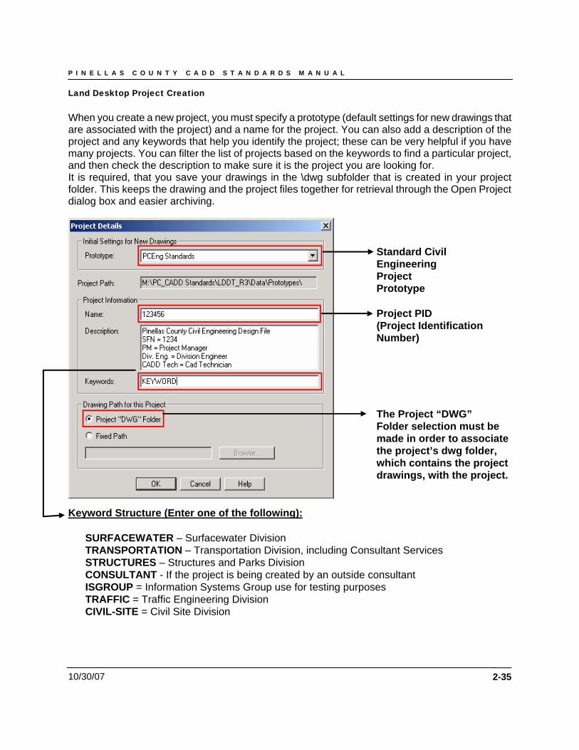
Land Desktop Project Creation When you create a new project, you must specify a prototype (default settings for new drawings that are associated with the project) and a name for the project. You can also add a description of the project and any keywords that help you identify the project; these can be very helpful if you have many projects. You can filter the list of projects based on the keywords to find a particular project, and then check the description to make sure it is the project you are looking for. It is required, that you save your drawings in the \dwg subfolder that is created in your project folder. This keeps the drawing and the project files together for retrieval through the Open Project dialog box and easier archiving.
2-35
Standard Civil
Engineering Project Prototype
Project PID (Project Identification Number)
The Project “DWG” Folder selection must be made in order to associate the project’s dwg folder, which contains the project drawings, with the project.
Keyword Structure (Enter one of the following): SURFACEWATER – Surfacewater Division TRANSPORTATION – Transportation Division, including Consultant Services STRUCTURES – Structures and Parks Division CONSULTANT - If the project is being created by an outside consultant ISGROUP = Information Systems Group use for testing purposes TRAFFIC = Traffic Engineering Division CIVIL-SITE = Civil Site Division
P I N E L L A S C O U N T Y C A D D S T A N D A R D S M A N U A L
10/30/07
S U P P O R T I N G D O C U M E N T I O N F O R C A D T A C M E M B E R S :
TAC Member (By Division) – Project Data Transfer Check List_v1.docIn addition, Land Desktop Projects have several key features that differentiate them from standard AutoCAD drawings. 1. You can assign a drawing to only one project, but you can change the project
association if necessary. 2. The project association is stored in the drawing file. Projects can contain many
drawings. All the drawings in a project share the same data files. 3. You are prompted to select a project if you open an existing drawing that is not assigned
to a project, or if the project is not found. 4. This assignment is saved when you save the drawing.
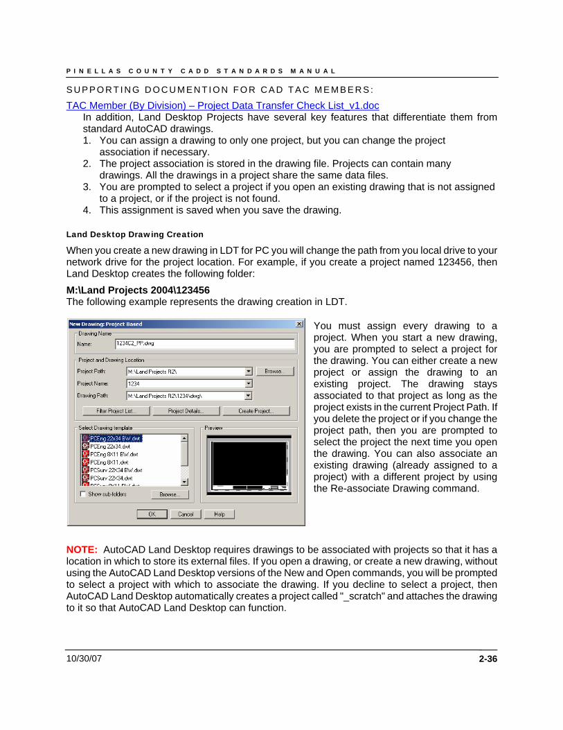
Land Desktop Drawing Creation
When you create a new drawing in LDT for PC you will change the path from you local drive to your network drive for the project location. For example, if you create a project named 123456, then Land Desktop creates the following folder: M:\Land Projects 2004\123456 The following example represents the drawing creation in LDT.
You must assign every drawing to a project. When you start a new drawing, you are prompted to select a project for the drawing. You can either create a new project or assign the drawing to an existing project. The drawing stays associated to that project as long as the project exists in the current Project Path. If you delete the project or if you change the project path, then you are prompted to select the project the next time you open the drawing. You can also associate an existing drawing (already assigned to a project) with a different project by using the Re-associate Drawing command.
NOTE: AutoCAD Land Desktop requires drawings to be associated with projects so that it has a location in which to store its external files. If you open a drawing, or create a new drawing, without using the AutoCAD Land Desktop versions of the New and Open commands, you will be prompted to select a project with which to associate the drawing. If you decline to select a project, then AutoCAD Land Desktop automatically creates a project called "_scratch" and attaches the drawing to it so that AutoCAD Land Desktop can function.
2-36
P I N E L L A S C O U N T Y C A D D S T A N D A R D S M A N U A L
10/30/07 2-37
Creating Projects Outside of AutoCAD Land Desktop It is not recommended to use Windows Explorer to create folders to use for AutoCAD Land Desktop projects. Use the Project Manager instead. The Project Manager ensures that the proper folder structure is created and the correct default files are copied into the new project. The Standard Engineering Project Management Directory Each project will have its own unique project directory that will contain engineering documentation of a supportive nature. This directory path will be within M:\Engineering Project Management. Upon creation of the Land Desktop project by the TAC Member for their respective division, they will manually create the associated Engineering Project Management folder within the aforementioned path. Directions for creation of this folder may be obtained from the following path: TAC Member (By Division) – Project Data Transfer Check List_v1.doc See the next page for the Engineering Project Management folder structure and explanation.
P I N E L L A S C O U N T Y C A D D S T A N D A R D S M A N U A L
10/30/07
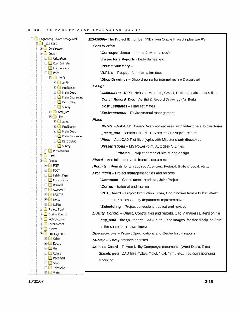
12345600\– The Project ID number (PID) from Oracle Projects plus two 0’s.
\Construction
\Correspondence – internal& external doc’s
\Inspector’s Reports - Daily dairies, etc…
\Permit Summary –
\R.F.I.’s – Request for information docs.
\Shop Drawings – Shop drawing for internal review & approval
\Design
\Calculation - ICPR, Heastad Methods, CHAN, Drainage calculations files
\Const Record_Dwg - As-Bid & Record Drawings (As-Built)
\Cost Estimates – Final estimates
\Environmental – Environmental management
\Plans
\DWF’s – AutoCAD Drawing Web Format Files, with Milestone sub-directories
\_meta_info - contains the PEDDS project and signature files.
\Plots – AutoCAD Plot files (*.plt), with Milestone sub-directories
\Presentations – MS PowerPoint, Autodesk VIZ files
\Photos – Project photos of site during design
\Fiscal - Administration and financial documents
\ Permits – Permits for all required Agencies, Federal, State & Local, etc…
\Proj_Mgmt – Project management files and records
\Contracts – Consultants, Interlocal, Joint Projects
\Corres – External and Internal
\PPT_Coord – Project Production Team, Coordination from a Public Works
and other Pinellas County department representative
\Scheduling – Project schedule is tracked and revised
\Quality_Control – Quality Control files and reports, Cad Managers Extension file
eng_data – the QC reports, ASCII output and images for that discipline (this
is the same for all disciplines)
\Specifications – Project Specifications and Geotechnical reports
\Survey – Survey archives and files
\Utilities_Coord – Private Utility Company’s documents (Word Doc’s, Excel
Speadsheets, CAD files (*.dwg, *.dwf, *.dxf, *.rml, etc…) by corresponding
discipline
2-38
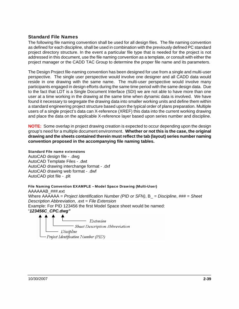
Standard File Names The following file naming convention shall be used for all design files. The file naming convention as defined for each discipline, shall be used in combination with the previously defined PC standard project directory structure. In the event a particular file type that is needed for the project is not addressed in this document, use the file naming convention as a template, or consult with either the project manager or the CADD TAC Group to determine the proper file name and its parameters. The Design Project file-naming convention has been designed for use from a single and multi-user perspective. The single user perspective would involve one designer and all CADD data would reside in one drawing with the same name. The multi-user perspective would involve many participants engaged in design efforts during the same time period with the same design data. Due to the fact that LDT is a Single Document Interface (SDI) we are not able to have more than one user at a time working in the drawing at the same time when dynamic data is involved. We have found it necessary to segregate the drawing data into smaller working units and define them within a standard engineering project structure based upon the typical order of plans preparation. Multiple users of a single project’s data can X-reference (XREF) this data into the current working drawing and place the data on the applicable X-reference layer based upon series number and discipline. NOTE: Some overlap in project drawing creation is expected to occur depending upon the design group’s need for a multiple document environment. Whether or not this is the case, the original drawing and the sheets contained therein must reflect the tab (layout) series number naming convention proposed in the accompanying file naming tables. Standard File name extensions AutoCAD design file - .dwg AutoCAD Template Files - .dwt AutoCAD drawing interchange format - .dxf AutoCAD drawing web format - .dwf AutoCAD plot file - .plt File Naming Convention EXAMPLE – Model Space Drawing (Multi-User) AAAAAAB_###.ext Where AAAAAA = Project Identification Number (PID or SFN), B_ = Discipline, ### = Sheet Description Abbreviation, .ext = File Extension Example: For PID 123456 the first Model Space sheet would be named: “123456C_CPC.dwg”
10/30/2007 2-39
P I N E L L A S C O U N T Y C A D D S T A N D A R D S M A N U A L
10/30/07
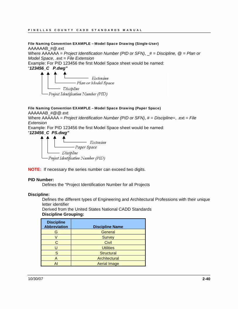
File Naming Convention EXAMPLE – Model Space Drawing (Single-User) AAAAAAB_#@.ext Where AAAAAA = Project Identification Number (PID or SFN), _# = Discipline, @ = Plan or Model Space, .ext = File Extension Example: For PID 123456 the first Model Space sheet would be named: “123456_C P.dwg”
File Naming Convention EXAMPLE – Model Space Drawing (Paper Space) AAAAAAB_#@@.ext Where AAAAAA = Project Identification Number (PID or SFN), # = Discipline=, .ext = File Extension Example: For PID 123456 the first Model Space sheet would be named: “123456_C PS.dwg”
NOTE: If necessary the series number can exceed two digits. PID Number:
Defines the "Project Identification Number for all Projects Discipline:
Defines the different types of Engineering and Architectural Professions with their unique letter identifier Derived from the United States National CADD Standards Discipline Grouping:
Discipline
Abbreviation Discipline Name G General V Survey C Civil U Utilities S Structural A Architectural AI Aerial Image
2-40
P I N E L L A S C O U N T Y C A D D S T A N D A R D S M A N U A L
10/30/07 2-41
File Extension:
Defines the typical group of layout sheets and their plan set organization as found within a standard set of Public Works Engineering Design plans.
Series Number Names for Layout Tab (Sheets):
Defines the numerical representation of the layout sheet description and the range of sheets available within that range or series. Layout sheets represent "TAB" names in Paperspace. • Number Series consist of number block ranges, which may be used to incorporate
additional layout sheets within that series. EX: Number Series 201 – PLAN - may include up to 100 sheets of each successively numbered up to Number Series (Example: 201, 202, 203…etc.)
P I N E L L A S C O U N T Y C A D D S T A N D A R D S M A N U A L
10/30/07
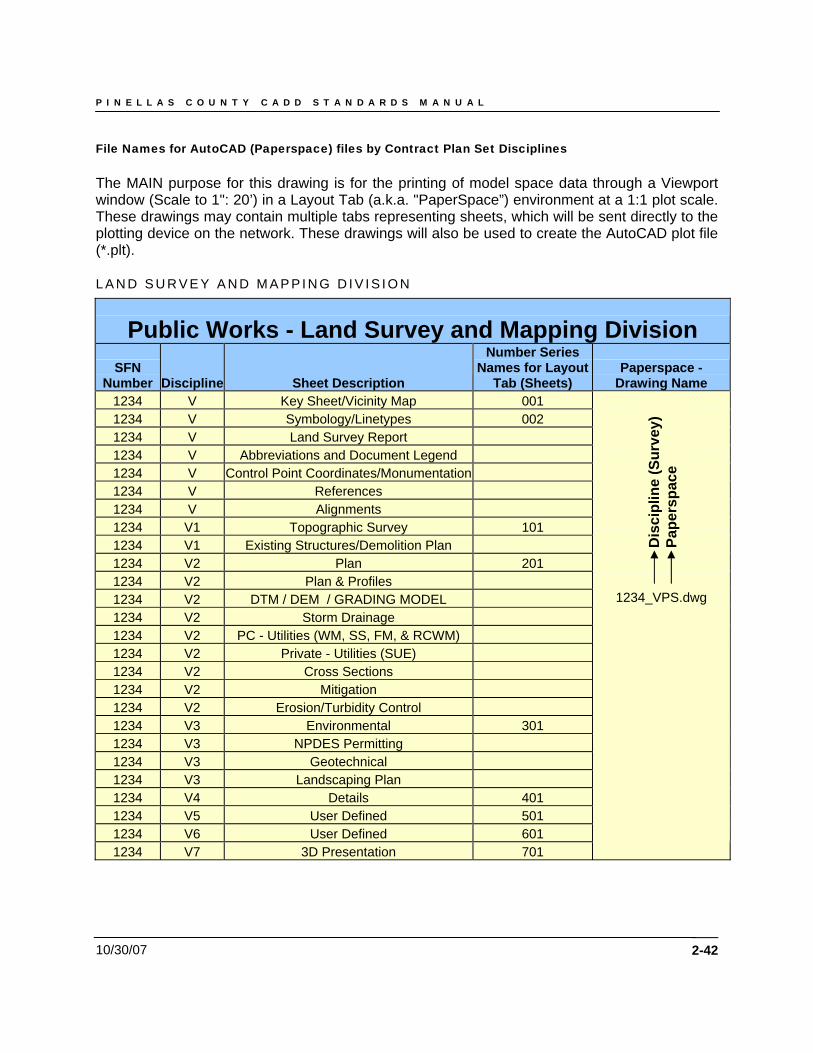
File Names for AutoCAD (Paperspace) files by Contract Plan Set Disciplines The MAIN purpose for this drawing is for the printing of model space data through a Viewport window (Scale to 1": 20’) in a Layout Tab (a.k.a. "PaperSpace”) environment at a 1:1 plot scale. These drawings may contain multiple tabs representing sheets, which will be sent directly to the plotting device on the network. These drawings will also be used to create the AutoCAD plot file (*.plt). L A N D S U R V E Y A N D M A P P I N G D I V I S I O N
Public Works - Land Survey and Mapping Division SFN
Number Discipline Sheet Description
Number Series Names for Layout
Tab (Sheets) Paperspace -
Drawing Name 1234 V Key Sheet/Vicinity Map 001 1234 V Symbology/Linetypes 002 1234 V Land Survey Report 1234 V Abbreviations and Document Legend 1234 V Control Point Coordinates/Monumentation 1234 V References 1234 V Alignments 1234 V1 Topographic Survey 101
2-42
1234 V1 Existing Structures/Demolition Plan 1234 V2 Plan 201 1234 V2 Plan & Profiles 1234 V2 DTM / DEM / GRADING MODEL 1234 V2 Storm Drainage 1234 V2 PC - Utilities (WM, SS, FM, & RCWM) 1234 V2 Private - Utilities (SUE) 1234 V2 Cross Sections 1234 V2 Mitigation 1234 V2 Erosion/Turbidity Control 1234 V3 Environmental 301 1234 V3 NPDES Permitting 1234 V3 Geotechnical 1234 V3 Landscaping Plan 1234 V4 Details 401 1234 V5 User Defined 501 1234 V6 User Defined 601
Dis
cipl
ine
(Sur
vey)
Pa
pers
pace
1234_VPS.dwg
3D Presentation 701 1234 V7
P I N E L L A S C O U N T Y C A D D S T A N D A R D S M A N U A L
10/30/07
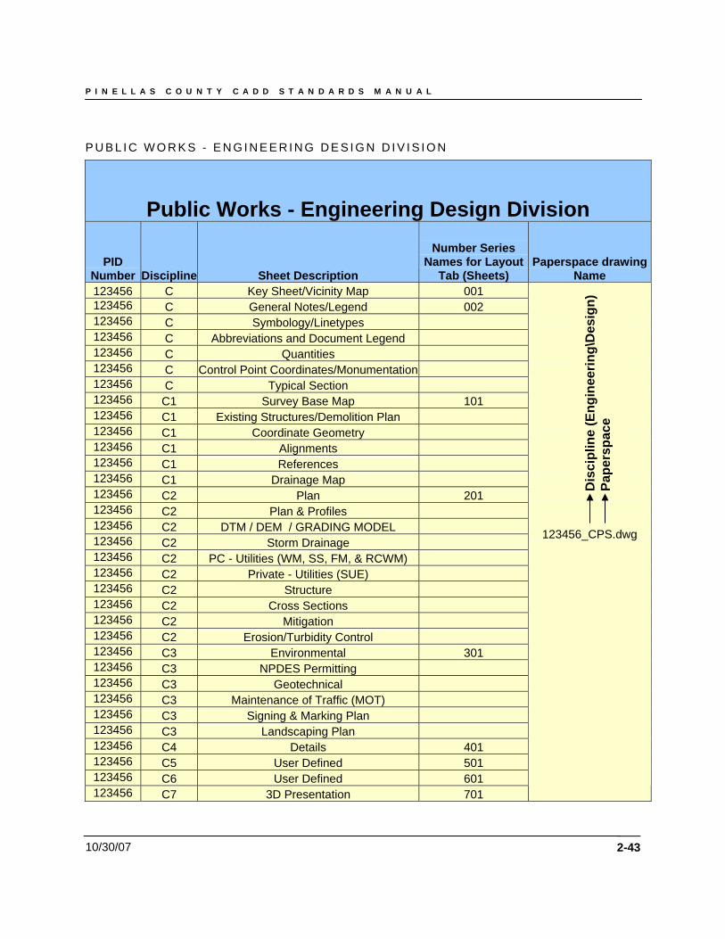
P U B L I C W O R K S - E N G I N E E R I N G D E S I G N D I V I S I O N
Public Works - Engineering Design Division
PID Number Discipline Sheet Description
Number Series Names for Layout
Tab (Sheets) Paperspace drawing
Name 123456 C Key Sheet/Vicinity Map 001 123456 C General Notes/Legend 002 123456 C Symbology/Linetypes 123456 C Abbreviations and Document Legend 123456 C Quantities 123456 C Control Point Coordinates/Monumentation 123456 C Typical Section 123456 C1 Survey Base Map 101 123456 C1 Existing Structures/Demolition Plan 123456 C1 Coordinate Geometry 123456 C1 Alignments 123456 C1 References 123456 C1 Drainage Map
2-43
123456 C2 Plan 201 123456 C2 Plan & Profiles 123456 C2 DTM / DEM / GRADING MODEL 123456 C2 Storm Drainage 123456 C2 PC - Utilities (WM, SS, FM, & RCWM) 123456 C2 Private - Utilities (SUE) 123456 C2 Structure 123456 C2 Cross Sections 123456 C2 Mitigation 123456 C2 Erosion/Turbidity Control 123456 C3 Environmental 301 123456 C3 NPDES Permitting 123456 C3 Geotechnical 123456 C3 Maintenance of Traffic (MOT) 123456 C3 Signing & Marking Plan 123456 C3 Landscaping Plan 123456 C4 Details 401 123456 C5 User Defined 501 123456 C6 User Defined 601 123456 C7 3D Presentation 701
Dis
cipl
ine
(Eng
inee
ring\
Des
ign)
Pa
pers
pace
123456_CPS.dwg
P I N E L L A S C O U N T Y C A D D S T A N D A R D S M A N U A L
10/30/07
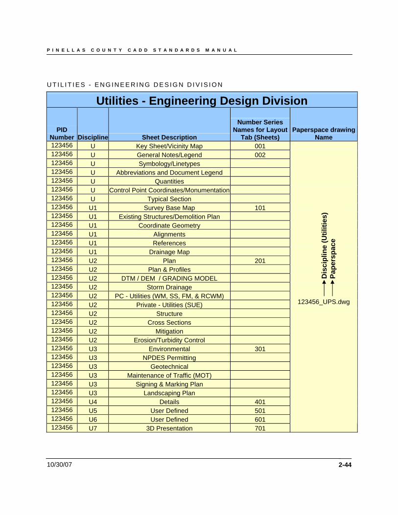
U T I L I T I E S - E N G I N E E R I N G D E S I G N D I V I S I O N
Utilities - Engineering Design Division
PID Number Discipline Sheet Description
Number Series Names for Layout
Tab (Sheets) Paperspace drawing
Name 123456 U Key Sheet/Vicinity Map 001 123456 U
2-44
General Notes/Legend 002 123456 U Symbology/Linetypes 123456 U Abbreviations and Document Legend 123456 U Quantities 123456 U Control Point Coordinates/Monumentation 123456 U Typical Section 123456 U1 Survey Base Map 101 123456 U1 Existing Structures/Demolition Plan 123456 U1 Coordinate Geometry 123456 U1 Alignments 123456 U1 References 123456 U1 Drainage Map 123456 U2 Plan 201 123456 U2 Plan & Profiles 123456 U2 DTM / DEM / GRADING MODEL 123456 U2 Storm Drainage 123456 U2 PC - Utilities (WM, SS, FM, & RCWM) 123456 U2 Private - Utilities (SUE) 123456 U2 Structure 123456 U2 Cross Sections 123456 U2 Mitigation 123456 U2 Erosion/Turbidity Control 123456 U3 Environmental 301 123456 U3 NPDES Permitting 123456 U3 Geotechnical 123456 U3 Maintenance of Traffic (MOT) 123456 U3 Signing & Marking Plan 123456 U3 Landscaping Plan 123456 U4 Details 401 123456 U5 User Defined 501 123456 U6 User Defined 601 123456 U7
123456_UPS.dwg
Dis
cipl
ine
(Util
ities
) Pa
pers
pace
3D Presentation 701
P I N E L L A S C O U N T Y C A D D S T A N D A R D S M A N U A L
10/30/07
S T R U C T U R A L E N G I N E E R I N G D E S I G N
Structural Engineering Design
PID Number Discipline Sheet Description
Number Series Names for Layout Tab
(Sheets) Paperspace
drawing Name 123456
2-45
S Key Sheet/Vicinity Map 001 123456 S General Notes/Legend 002 123456 S Symbology/Linetypes 123456 S Abbreviations and Document Legend 123456 S Control Point Coordinates/Monumentation 123456 S1 Survey Base Map 101 123456 S1 Existing Structures/Demolition Plan 123456 S1 Alignments 123456 S2 Site Plan 201 123456 S2 Framing Plan 123456 S2 Foundation Plan 123456 S2 Elevation Plan 123456 S2 PC - Utilities (WM, SS, FM, & RCWM) 123456 S2 Private - Utilities (SUE) 123456 S2 Cross Sections 123456 S2 Erosion/Turbidity Control 123456 S2 Environmental 123456 S2 Sections 123456 S3 Schedules 301 123456 S3 Isometric/3D Plan 123456 S3 Diagrams 123456 S3 Geotechnical 123456 S4 Details 401 123456 S5 User Defined 501 123456 S6 User Defined 601 123456 S7 3D Presentation 701
123456_SPS.dwg D
isci
plin
e (S
truc
tura
l)
Pape
rspa
ce
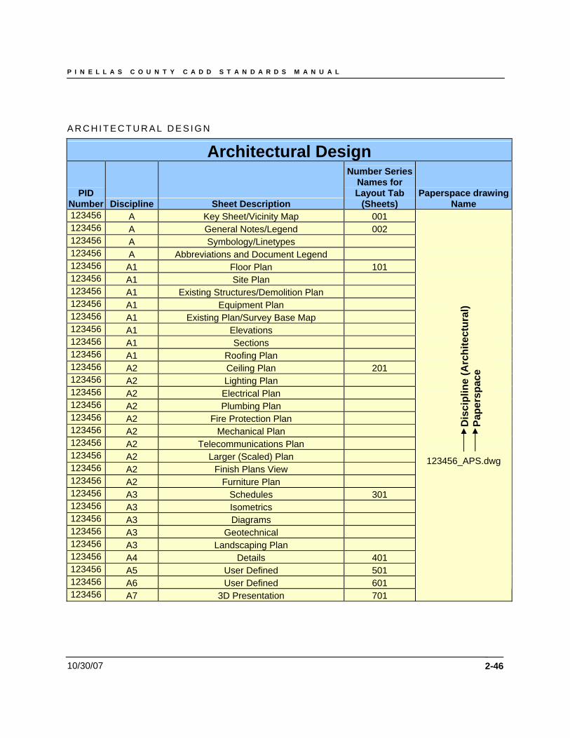
P I N E L L A S C O U N T Y C A D D S T A N D A R D S M A N U A L
10/30/07
A R C H I T E C T U R A L D E S I G N
Architectural Design
PID Number Discipline Sheet Description
Number Series Names for Layout Tab
(Sheets) Paperspace drawing
Name 123456 A
2-46
Key Sheet/Vicinity Map 001 123456 A General Notes/Legend 002 123456 A Symbology/Linetypes 123456 A Abbreviations and Document Legend 123456 A1 Floor Plan 101 123456 A1 Site Plan 123456 A1 Existing Structures/Demolition Plan 123456 A1 Equipment Plan 123456 A1 Existing Plan/Survey Base Map 123456 A1 Elevations 123456 A1 Sections 123456 A1 Roofing Plan 123456 A2 Ceiling Plan 201 123456 A2 Lighting Plan 123456 A2 Electrical Plan 123456 A2 Plumbing Plan 123456 A2 Fire Protection Plan 123456 A2 Mechanical Plan 123456 A2 Telecommunications Plan 123456 A2 Larger (Scaled) Plan 123456 A2 Finish Plans View 123456 A2 Furniture Plan 123456 A3 Schedules 301 123456 A3 Isometrics 123456 A3 Diagrams 123456 A3 Geotechnical 123456 A3 Landscaping Plan 123456 A4 Details 401 123456 A5 User Defined 501 123456 A6 User Defined 601 123456
Dis
cipl
ine
(Arc
hite
ctur
al)
Pape
rspa
ce
123456_APS.dwg
3D Presentation 701 A7
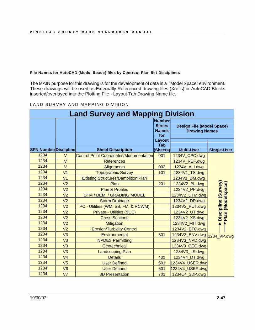
P I N E L L A S C O U N T Y C A D D S T A N D A R D S M A N U A L
10/30/07
File Names for AutoCAD (Model Space) files by Contract Plan Set Disciplines The MAIN purpose for this drawing is for the development of data in a "Model Space" environment. These drawings will be used as Externally Referenced drawing files (Xref's) or AutoCAD Blocks inserted/overlayed into the Plotting File - Layout Tab Drawing Name file. L A N D S U R V E Y A N D M A P P I N G D I V I S I O N
Land Survey and Mapping Division
Design File (Model Space) Drawing Names
SFN Number Discipline Sheet Description
Number Series Names
for Layout
Tab (Sheets)
Multi-User
Single-User
1234 V Control Point Coordinates/Monumentation 001
2-47
1234V_CPC.dwg 1234 V References 1234V_REF.dwg 1234 V Alignments 002 1234V_ALI.dwg 1234 V1 Topographic Survey 101 1234V1_TS.dwg 1234 V1 Existing Structures/Demolition Plan 1234V1_DM.dwg 1234 V2 Plan 201 1234V2_PL.dwg 1234 V2 Plan & Profiles 1234V2_PP.dwg 1234 V2 DTM / DEM / GRADING MODEL 1234V2_DTM.dwg1234 V2 Storm Drainage 1234V2_DR.dwg 1234 V2 PC - Utilities (WM, SS, FM, & RCWM) 1234V2_PUT.dwg1234 V2 Private - Utilities (SUE) 1234V2_UT.dwg 1234 V2 Cross Sections 1234V2_XS.dwg 1234 V2 Mitigation 1234V2_MIT.dwg 1234 V2 Erosion/Turbidity Control 1234V2_ETC.dwg1234 V3 Environmental 301 1234V3_ENV.dwg1234 V3 NPDES Permitting 1234V3_NPD.dwg1234 V3 Geotechnical 1234V3_GEO.dwg1234 V3 Landscaping Plan 1234V3_LS.dwg 1234 V4 Details 401 1234V4_DT.dwg 1234 V5 User Defined 501 1234V4_USER.dwg1234 V6 User Defined 601 1234V4_USER.dwg1234 V7
1234_VP.dwg
Dis
cipl
ine
(Sur
vey)
Pl
an (M
odel
spac
e)
701 1234C4_3DP.dwg3D Presentation

P I N E L L A S C O U N T Y C A D D S T A N D A R D S M A N U A L
10/30/07 2-48
Land Survey and Mapping Division – File Diagram
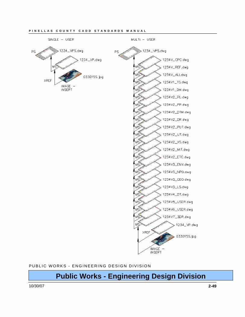
P I N E L L A S C O U N T Y C A D D S T A N D A R D S M A N U A L
10/30/07
P U B L I C W O R K S - E N G I N E E R I N G D E S I G N D I V I S I O N
Public Works - Engineering Design Division
2-49
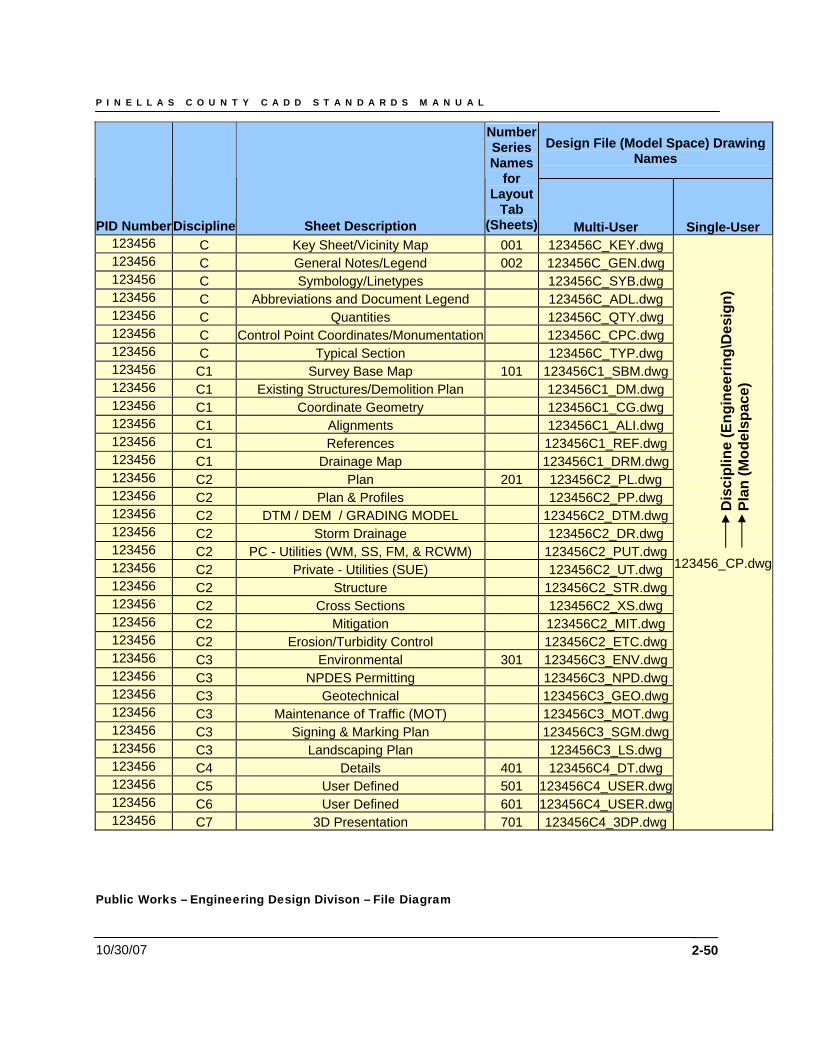
P I N E L L A S C O U N T Y C A D D S T A N D A R D S M A N U A L
10/30/07
Design File (Model Space) Drawing Names
PID Number Discipline Sheet Description
Number Series Names
for Layout
Tab (Sheets) Multi-User Single-User
123456 C Key Sheet/Vicinity Map
2-50
001 123456C_KEY.dwg 123456 C General Notes/Legend 002 123456C_GEN.dwg 123456 C Symbology/Linetypes 123456C_SYB.dwg 123456 C Abbreviations and Document Legend 123456C_ADL.dwg 123456 C Quantities 123456C_QTY.dwg 123456 C Control Point Coordinates/Monumentation 123456C_CPC.dwg 123456 C Typical Section 123456C_TYP.dwg 123456 C1 Survey Base Map 101 123456C1_SBM.dwg123456 C1 Existing Structures/Demolition Plan 123456C1_DM.dwg 123456 C1 Coordinate Geometry 123456C1_CG.dwg 123456 C1 Alignments 123456C1_ALI.dwg 123456 C1 References 123456C1_REF.dwg123456 C1 Drainage Map 123456C1_DRM.dwg123456 C2 Plan 201 123456C2_PL.dwg 123456 C2 Plan & Profiles 123456C2_PP.dwg 123456 C2 DTM / DEM / GRADING MODEL 123456C2_DTM.dwg123456 C2 Storm Drainage 123456C2_DR.dwg 123456 C2 PC - Utilities (WM, SS, FM, & RCWM) 123456C2_PUT.dwg123456 C2 Private - Utilities (SUE) 123456C2_UT.dwg 123456 C2 Structure 123456C2_STR.dwg123456 C2 Cross Sections 123456C2_XS.dwg 123456 C2 Mitigation 123456C2_MIT.dwg 123456 C2 Erosion/Turbidity Control 123456C2_ETC.dwg123456 C3 Environmental 301 123456C3_ENV.dwg123456 C3 NPDES Permitting 123456C3_NPD.dwg123456 C3 Geotechnical 123456C3_GEO.dwg123456 C3 Maintenance of Traffic (MOT) 123456C3_MOT.dwg123456 C3 Signing & Marking Plan 123456C3_SGM.dwg123456 C3 Landscaping Plan 123456C3_LS.dwg 123456 C4 Details 401 123456C4_DT.dwg 123456 C5 User Defined 501 123456C4_USER.dwg123456 C6 User Defined 601 123456C4_USER.dwg123456 C7 3D Presentation 701 123456C4_3DP.dwg
123456_CP.dwg
Dis
cipl
ine
(Eng
inee
ring\
Des
ign)
Pl
an (M
odel
spac
e)
Public Works – Engineering Design Divison – File Diagram
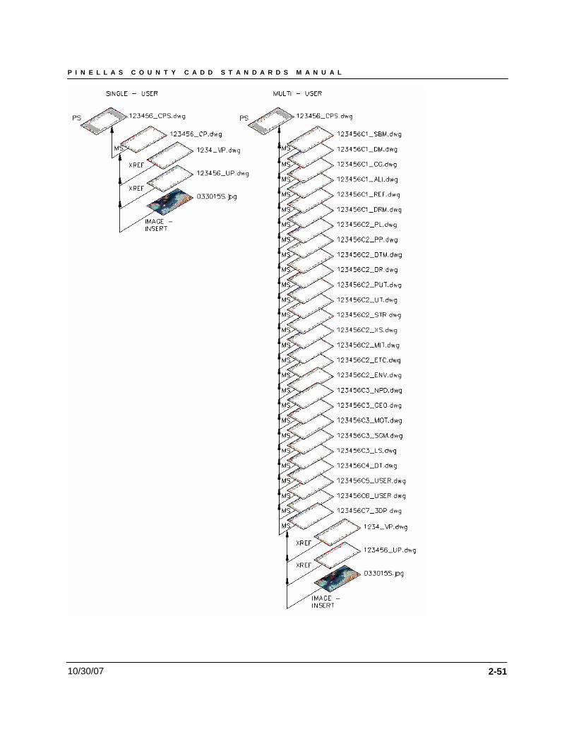
P I N E L L A S C O U N T Y C A D D S T A N D A R D S M A N U A L
10/30/07
2-51
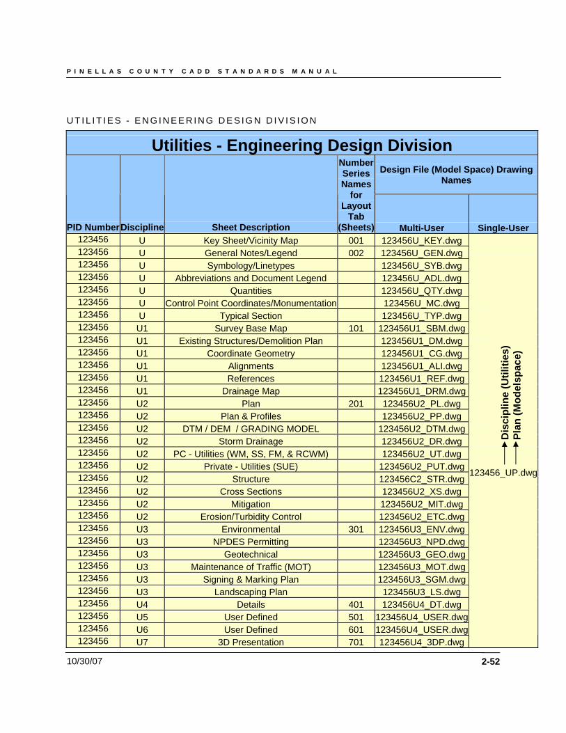
P I N E L L A S C O U N T Y C A D D S T A N D A R D S M A N U A L
10/30/07
U T I L I T I E S - E N G I N E E R I N G D E S I G N D I V I S I O N
Utilities - Engineering Design Division
Design File (Model Space) Drawing Names
PID Number Discipline Sheet Description
Number Series Names
for Layout
Tab (Sheets) Multi-User Single-User
123456
2-52
U Key Sheet/Vicinity Map 001 123456U_KEY.dwg 123456 U General Notes/Legend 002 123456U_GEN.dwg 123456 U Symbology/Linetypes 123456U_SYB.dwg 123456 U Abbreviations and Document Legend 123456U_ADL.dwg 123456 U Quantities 123456U_QTY.dwg 123456 U Control Point Coordinates/Monumentation 123456U_MC.dwg 123456 U Typical Section 123456U_TYP.dwg 123456 U1 Survey Base Map 101 123456U1_SBM.dwg123456 U1 Existing Structures/Demolition Plan 123456U1_DM.dwg 123456 U1 Coordinate Geometry 123456U1_CG.dwg 123456 U1 Alignments 123456U1_ALI.dwg 123456 U1 References 123456U1_REF.dwg123456 U1 Drainage Map 123456U1_DRM.dwg123456 U2 Plan 201 123456U2_PL.dwg 123456 U2 Plan & Profiles 123456U2_PP.dwg 123456 U2 DTM / DEM / GRADING MODEL 123456U2_DTM.dwg123456 U2 Storm Drainage 123456U2_DR.dwg 123456 U2 PC - Utilities (WM, SS, FM, & RCWM) 123456U2_UT.dwg 123456 U2 Private - Utilities (SUE) 123456U2_PUT.dwg123456 U2 Structure 123456C2_STR.dwg123456 U2 Cross Sections 123456U2_XS.dwg 123456 U2 Mitigation 123456U2_MIT.dwg 123456 U2 Erosion/Turbidity Control 123456U2_ETC.dwg123456 U3 Environmental 301 123456U3_ENV.dwg123456 U3 NPDES Permitting 123456U3_NPD.dwg123456 U3 Geotechnical 123456U3_GEO.dwg123456 U3 Maintenance of Traffic (MOT) 123456U3_MOT.dwg123456 U3 Signing & Marking Plan 123456U3_SGM.dwg123456 U3 Landscaping Plan 123456U3_LS.dwg 123456 U4 Details 401 123456U4_DT.dwg 123456 U5 User Defined 501 123456U4_USER.dwg123456 U6 User Defined 601 123456U4_USER.dwg123456
123456_UP.dwg
3D Presentation 701 123456U4_3DP.dwgU7
Dis
cipl
ine
(Util
ities
) Pl
an (M
odel
spac
e)
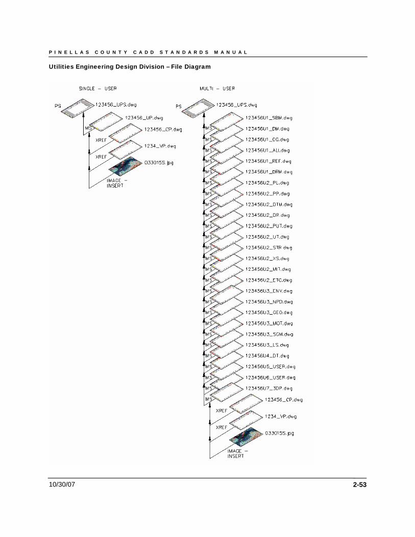
P I N E L L A S C O U N T Y C A D D S T A N D A R D S M A N U A L
10/30/07
Utilities Engineering Design Division – File Diagram
2-53
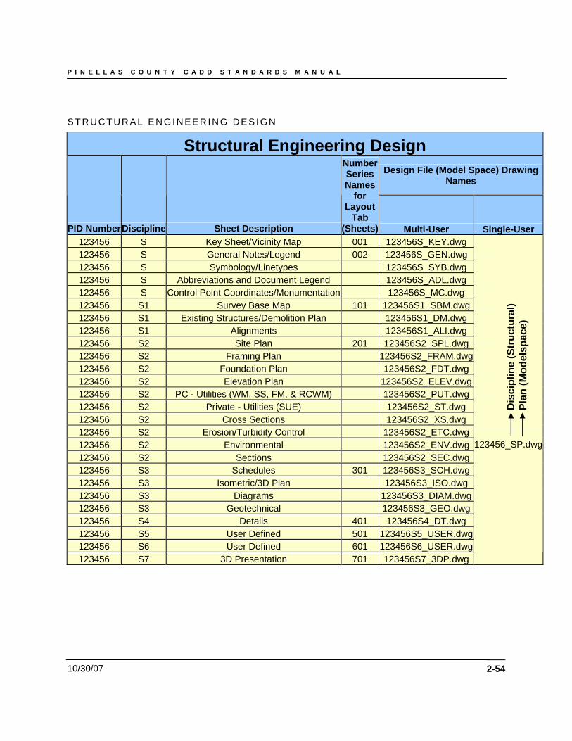
P I N E L L A S C O U N T Y C A D D S T A N D A R D S M A N U A L
10/30/07
S T R U C T U R A L E N G I N E E R I N G D E S I G N
Structural Engineering Design
Design File (Model Space) Drawing Names
PID Number Discipline Sheet Description
Number Series Names
for Layout
Tab (Sheets) Multi-User Single-User
123456
2-54
S Key Sheet/Vicinity Map 001 123456S_KEY.dwg 123456 S General Notes/Legend 002 123456S_GEN.dwg 123456 S Symbology/Linetypes 123456S_SYB.dwg 123456 S Abbreviations and Document Legend 123456S_ADL.dwg 123456 S Control Point Coordinates/Monumentation 123456S_MC.dwg 123456 S1 Survey Base Map 101 123456S1_SBM.dwg123456 S1 Existing Structures/Demolition Plan 123456S1_DM.dwg 123456 S1 Alignments 123456S1_ALI.dwg 123456 S2 Site Plan 201 123456S2_SPL.dwg123456 S2 Framing Plan 123456S2_FRAM.dwg123456 S2 Foundation Plan 123456S2_FDT.dwg123456 S2 Elevation Plan 123456S2_ELEV.dwg123456 S2 PC - Utilities (WM, SS, FM, & RCWM) 123456S2_PUT.dwg123456 S2 Private - Utilities (SUE) 123456S2_ST.dwg 123456 S2 Cross Sections 123456S2_XS.dwg 123456 S2 Erosion/Turbidity Control 123456S2_ETC.dwg123456 S2 Environmental 123456S2_ENV.dwg123456 S2 Sections 123456S2_SEC.dwg123456 S3 Schedules 301 123456S3_SCH.dwg123456 S3 Isometric/3D Plan 123456S3_ISO.dwg 123456 S3 Diagrams 123456S3_DIAM.dwg123456 S3 Geotechnical 123456S3_GEO.dwg123456 S4 Details 401 123456S4_DT.dwg 123456 S5 User Defined 501 123456S5_USER.dwg123456 S6 User Defined 601 123456S6_USER.dwg
123456_SP.dwg
Dis
cipl
ine
(Str
uctu
ral)
Pl
an (M
odel
spac
e)
S7 3D Presentation 701 123456S7_3DP.dwg123456
P I N E L L A S C O U N T Y C A D D S T A N D A R D S M A N U A L
10/30/07 2-55

P I N E L L A S C O U N T Y C A D D S T A N D A R D S M A N U A L
10/30/07
Structural Engineering Design – File Diagram
2-56
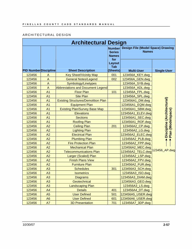
P I N E L L A S C O U N T Y C A D D S T A N D A R D S M A N U A L
10/30/07
A R C H I T E C T U R A L D E S I G N
Architectural Design Design File (Model Space) Drawing
Names
PID Number Discipline Sheet Description
Number Series Names
for Layout
Tab (Sheets) Multi-User Single-User
123456 A Key Sheet/Vicinity Map 001 123456A_KEY.dwg 123456 A General Notes/Legend 002 123456A_GEN.dwg 123456 A Symbology/Linetypes 123456A_SYB.dwg 123456 A Abbreviations and Document Legend 123456A_ADL.dwg 123456 A1 Floor Plan 101 123456A_FPL.dwg 123456 A1 Site Plan 123456A_SPL.dwg 123456 A1 Existing Structures/Demolition Plan 123456A1_DM.dwg 123456 A1 Equipment Plan 123456A1_EQM.dwg 123456 A1 Existing Plan/Survey Base Map 123456A1_SBM.dwg 123456 A1 Elevations 123456A1_ELEV.dwg
2-57
123456 A1 Sections 123456A1_SEC.dwg 123456 A1 Roofing Plan 123456A1_ROF.dwg 123456 A2 Ceiling Plan 201 123456A2_CP.dwg 123456 A2 Lighting Plan 123456A2_LG.dwg 123456 A2 Electrical Plan 123456A2_ELEC.dwg 123456 A2 Plumbing Plan 123456A2_PLB.dwg 123456 A2 Fire Protection Plan 123456A2_FPP.dwg 123456 A2 Mechanical Plan 123456A2_MEC.dwg 123456 A2 Telecommunications Plan 123456A2_TELC.dwg 123456 A2 Larger (Scaled) Plan 123456A2_LSP.dwg 123456 A2 Finish Plans View 123456A2_FPV.dwg 123456 A2 Furniture Plan 123456A2_FUR.dwg 123456 A3 Schedules 301 123456A3_SCH.dwg 123456 A3 Isometrics 123456A3_ISO.dwg 123456 A3 Diagrams 123456A3_DIAM.dwg 123456 A3 Geotechnical 123456A3_GEO.dwg 123456 A3 Landscaping Plan 123456A3_LS.dwg 123456 A4 Details 401 123456A4_DT.dwg 123456 A5 User Defined 501 123456A5_USER.dwg 123456 A6 User Defined 601 123456A6_USER.dwg
Dis
cipl
ine
(Arc
hite
ctur
al)
Plan
(Mod
elsp
ace)
123456_AP.dwg
123456 A7 3D Presentation 701 123456A7_3DP.dwg
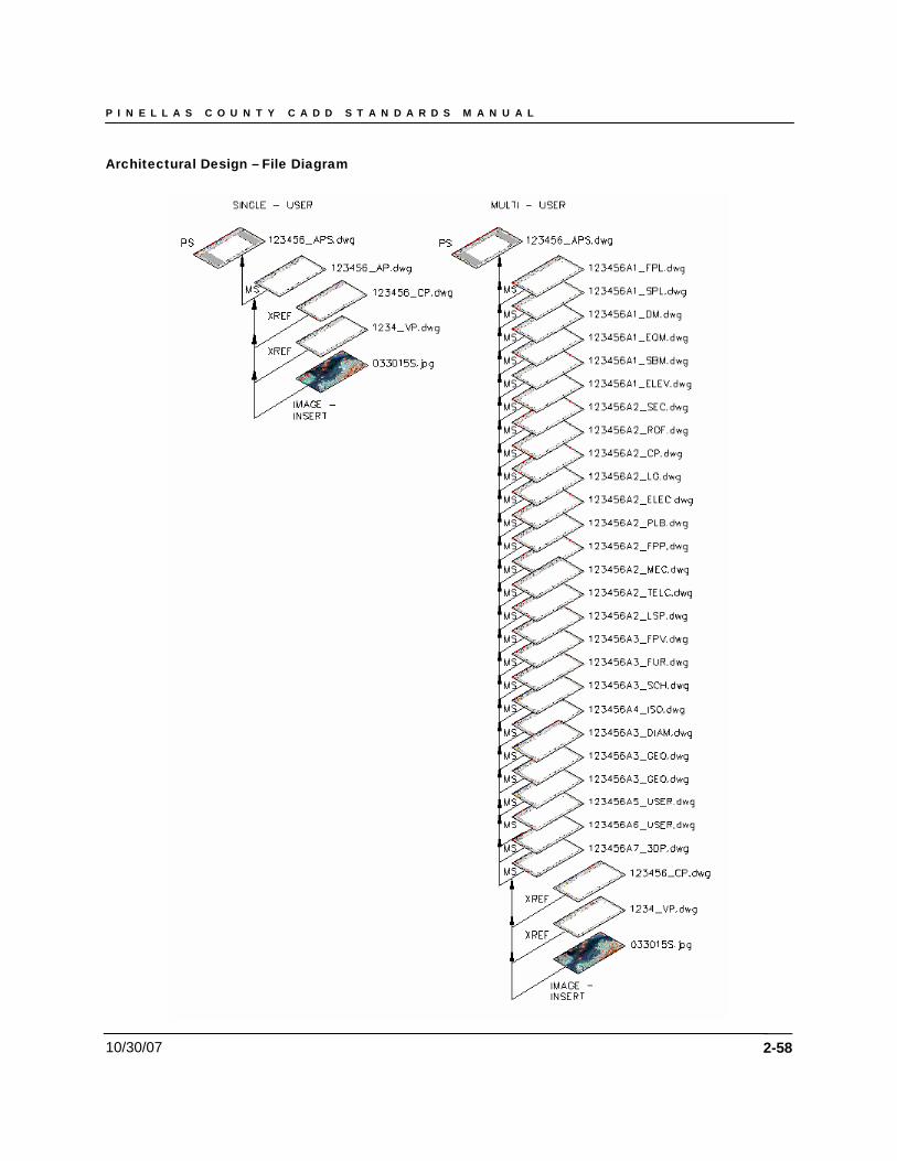
P I N E L L A S C O U N T Y C A D D S T A N D A R D S M A N U A L
10/30/07
Architectural Design – File Diagram
2-58
P I N E L L A S C O U N T Y C A D D S T A N D A R D S M A N U A L
10/30/07 2-59
File Names for AutoCAD (Plot) files by Contract Plan Set Disciplines Chapter 2 of the PC CADD Project Administration Manual specifies the requirement for the production of Plot Files representing each sheet in the plan set and potentially other documents. Plot files for the plans set are generated from AutoCAD, and must be produced to scale (1” on paper = 1” in the plot file). The plot files will be produced in HPGL2 format. PC supplies configurations for AutoCAD sufficient to produce plot files in HPGL2 format from AutoCAD plot drivers. Plot file naming conventions shall follow the naming convention of the source AutoCAD design file from which it is generated, with the addition of a sheet tab number if necessary. For AutoCAD files that will generate multiple sheet plot files, the sheet tab number will be added to the filename. NOTE: If necessary the series number can exceed three digits. Autodesk provides a plotting utility called Batch Plot Utility. This utility runs from the Windows desktop, and calls AutoCAD (which must be present on the user’s workstation) to execute batch plotting and the production of the HP-GL/2 Plot files for the plan sheets. It is highly encouraged users take advantage of this program to produce the HP-GL/2 Plot files, however the user may use an alternate plotting method (AutoCAD Print/Plot or Batch Print/Plot utility) to achieve similar results. No matter which method is used, the minimum resolution for the HP-GL/2 driver (.plt file in AutoCAD) should be set to 300 (min.) to meet the Department of State, Chapter 1B-26.003(10) Selection of Electronic Records Storage Media requirements. A resolution of 600 dpi or higher is preferred for plans using Black & White or Color Aerial images. If an alternate plotting method is used, the user is solely responsible to ensure that the resulting HP-GL/2 Plot files meet the criteria specified herein.
File Names for AutoCAD (DWF ePlot) files by Contract Plan Set Disciplines With ePlot, you can publish electronic drawing files to the Web, or the project collaboration site. The files you create are stored in drawing web format (DWF). DWF files can be opened and viewed and redlined by anyone using Volo View Express. NOTE: These files will be stored in the EPM folder structure (Example: M:\Engineering Project Management\_PIDMaster\Design\DWF's) under the appropriate PID project based on completion of a project milestone.
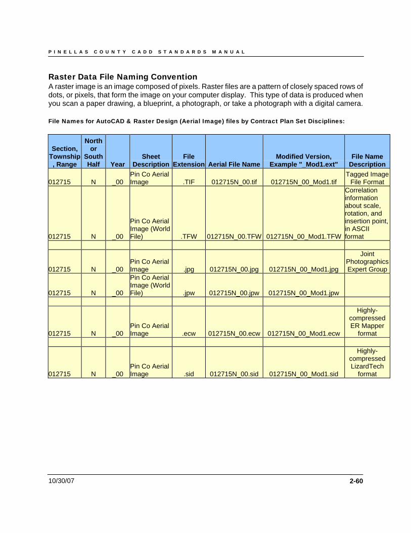
P I N E L L A S C O U N T Y C A D D S T A N D A R D S M A N U A L
10/30/07 2-60
Raster Data File Naming Convention A raster image is an image composed of pixels. Raster files are a pattern of closely spaced rows of dots, or pixels, that form the image on your computer display. This type of data is produced when you scan a paper drawing, a blueprint, a photograph, or take a photograph with a digital camera. File Names for AutoCAD & Raster Design (Aerial Image) files by Contract Plan Set Disciplines:
Section, Township, Range
North or
South Half Year
Sheet Description
File Extension Aerial File Name
Modified Version, Example "_Mod1.ext"
File Name Description
012715 N _00 Pin Co Aerial Image .TIF 012715N_00.tif 012715N_00_Mod1.tif
Tagged Image File Format
012715 N _00
Pin Co Aerial Image (World File) .TFW 012715N_00.TFW 012715N_00_Mod1.TFW
Correlation information about scale, rotation, and insertion point, in ASCII format
012715 N _00 Pin Co Aerial Image .jpg 012715N_00.jpg 012715N_00_Mod1.jpg
Joint Photographics Expert Group
012715 N _00
Pin Co Aerial Image (World File) .jpw 012715N_00.jpw 012715N_00_Mod1.jpw
012715 N _00 Pin Co Aerial Image .ecw 012715N_00.ecw 012715N_00_Mod1.ecw
Highly-compressed ER Mapper
format
012715 N _00 Pin Co Aerial Image .sid 012715N_00.sid 012715N_00_Mod1.sid
Highly-compressed LizardTech
format
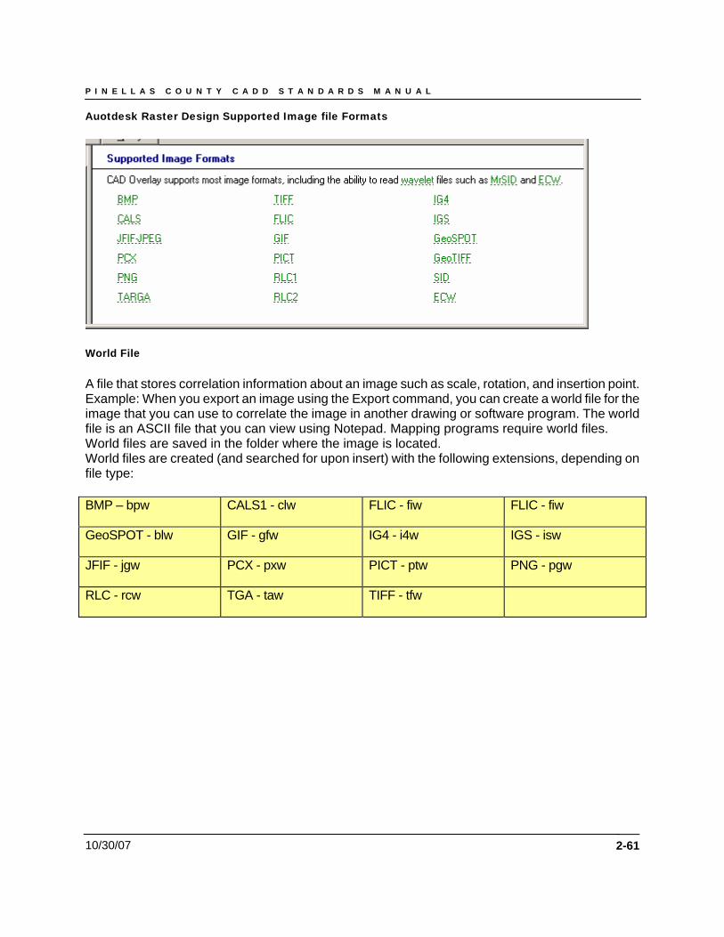
P I N E L L A S C O U N T Y C A D D S T A N D A R D S M A N U A L
10/30/07
Auotdesk Raster Design Supported Image file Formats
World File A file that stores correlation information about an image such as scale, rotation, and insertion point. Example: When you export an image using the Export command, you can create a world file for the image that you can use to correlate the image in another drawing or software program. The world file is an ASCII file that you can view using Notepad. Mapping programs require world files. World files are saved in the folder where the image is located. World files are created (and searched for upon insert) with the following extensions, depending on file type: BMP – bpw CALS1 - clw FLIC - fiw FLIC - fiw
GeoSPOT - blw GIF - gfw IG4 - i4w IGS - isw
JFIF - jgw PCX - pxw PICT - ptw PNG - pgw
RLC - rcw TGA - taw TIFF - tfw
2-61
10/30/2007 2-62
Chapter 4
Land Survey and Mapping Division
10/30/2007 2-63
Chapter 4 - Land Survey and Mapping Division Points Project data points consist of existing engineering data gathered from the project location as determined by the project’s PM to assist in the engineering development process. Project data points contain both horizontal and vertical data relative to the chosen coordinate zone – NAD 83/90, NGVD 88. Points by Range The point range for the Land Survey and Mapping Division is specified below:
• Control Point data – collected point data representative of known field locations and referenced to the chosen coordinate zone. All Pinellas County Land Survey points shall reside within the point range of 0 - 100.
• Project Point data – data representative of the project limits as defined by the project’s PM. All Pinellas County Land Survey project point data shall occupy the point range of 101 - 100,000.
NOTE: If additional project data points are required prior to survey acquisition, it will be necessary for the PM to specify a NAP, or Next Available Point number.
Point Format Project data will be represented and contained within a comma-delimited file stored with the project. The desired data point format for the Land Survey and Mapping Division as follows: FIELD ONE --- Point Identifier Number FIELD TWO --- North Coordinate Value FIELD THREE --- East Coordinate Value FIELD FOUR --- Point Elevation FIELD FIVE --- Point Code Identifier FIELD SIX --- Clarification Note Point Groups Project data points will be organized into groups within LDT to facilitate more efficient point data management and utilization. The standard point groups used by the Land Survey and Mapping Division are listed below:
1. ALL – All survey points in the acquired data point set 2. Hard Shots – survey data points which represent pavement or man-made features 3. Roadway – All information relating to roadway features – (EP, BC, CL, ETC.) 4. Monuments/Control – known field point data used to establish the survey’s base 5. Ground Points – GP or Soft Shots – points taken at arbitrary locations along the existing
terrain 6. Breaklines – a linear or polygonal interruption in the current surface elevation that is
used to distinguish objects of a dissimilar nature, i.e., walls, building pads, structures, etc.
7. Trees – those found on the site of the requested survey
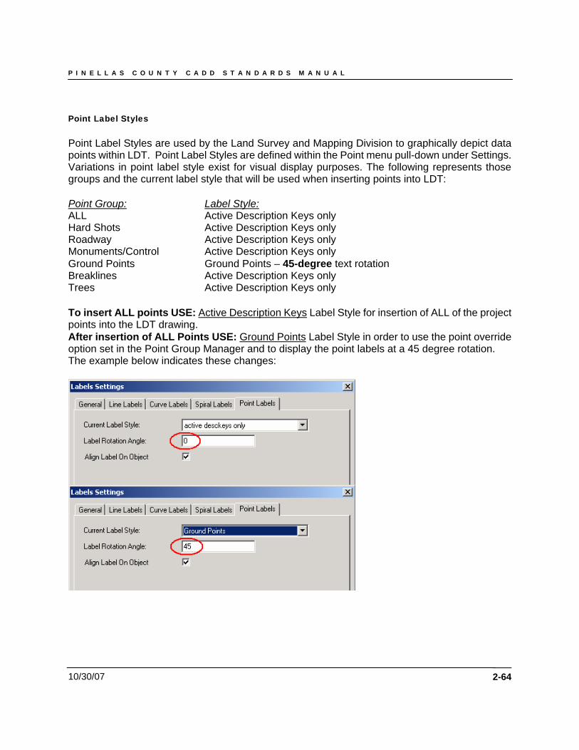
P I N E L L A S C O U N T Y C A D D S T A N D A R D S M A N U A L
10/30/07
Point Label Styles Point Label Styles are used by the Land Survey and Mapping Division to graphically depict data points within LDT. Point Label Styles are defined within the Point menu pull-down under Settings. Variations in point label style exist for visual display purposes. The following represents those groups and the current label style that will be used when inserting points into LDT: Point Group: Label Style: ALL Active Description Keys only Hard Shots Active Description Keys only Roadway Active Description Keys only Monuments/Control Active Description Keys only Ground Points Ground Points – 45-degree text rotation Breaklines Active Description Keys only Trees Active Description Keys only To insert ALL points USE: Active Description Keys Label Style for insertion of ALL of the project points into the LDT drawing. After insertion of ALL Points USE: Ground Points Label Style in order to use the point override option set in the Point Group Manager and to display the point labels at a 45 degree rotation. The example below indicates these changes:
2-64
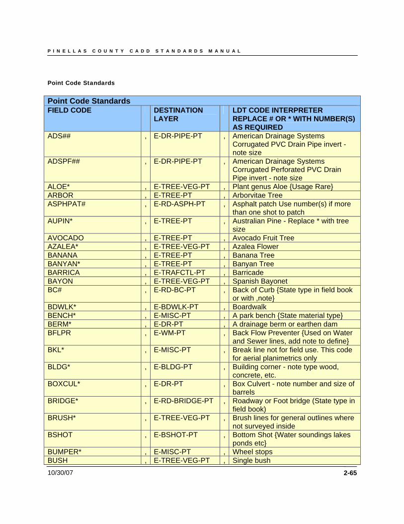
P I N E L L A S C O U N T Y C A D D S T A N D A R D S M A N U A L
10/30/07 2-65
Point Code Standards Point Code Standards FIELD CODE DESTINATION
LAYER LDT CODE INTERPRETER
REPLACE # OR * WITH NUMBER(S) AS REQUIRED
ADS## , E-DR-PIPE-PT , American Drainage Systems Corrugated PVC Drain Pipe invert - note size
ADSPF## , E-DR-PIPE-PT , American Drainage Systems Corrugated Perforated PVC Drain Pipe invert - note size
ALOE* , E-TREE-VEG-PT , Plant genus Aloe {Usage Rare} ARBOR , E-TREE-PT , Arborvitae Tree ASPHPAT# , E-RD-ASPH-PT , Asphalt patch Use number(s) if more
than one shot to patch AUPIN* , E-TREE-PT , Australian Pine - Replace * with tree
size AVOCADO , E-TREE-PT , Avocado Fruit Tree AZALEA* , E-TREE-VEG-PT , Azalea Flower BANANA , E-TREE-PT , Banana Tree BANYAN* , E-TREE-PT , Banyan Tree BARRICA , E-TRAFCTL-PT , Barricade BAYON , E-TREE-VEG-PT , Spanish Bayonet BC# , E-RD-BC-PT , Back of Curb {State type in field book
or with ,note} BDWLK* , E-BDWLK-PT , Boardwalk BENCH* , E-MISC-PT , A park bench {State material type} BERM* , E-DR-PT , A drainage berm or earthen dam BFLPR , E-WM-PT , Back Flow Preventer {Used on Water
and Sewer lines, add note to define} BKL* , E-MISC-PT , Break line not for field use. This code
for aerial planimetrics only BLDG* , E-BLDG-PT , Building corner - note type wood,
concrete, etc. BOXCUL* , E-DR-PT , Box Culvert - note number and size of
barrels BRIDGE* , E-RD-BRIDGE-PT , Roadway or Foot bridge (State type in
field book) BRUSH* , E-TREE-VEG-PT , Brush lines for general outlines where
not surveyed inside BSHOT , E-BSHOT-PT , Bottom Shot {Water soundings lakes
ponds etc} BUMPER* , E-MISC-PT , Wheel stops BUSH , E-TREE-VEG-PT , Single bush
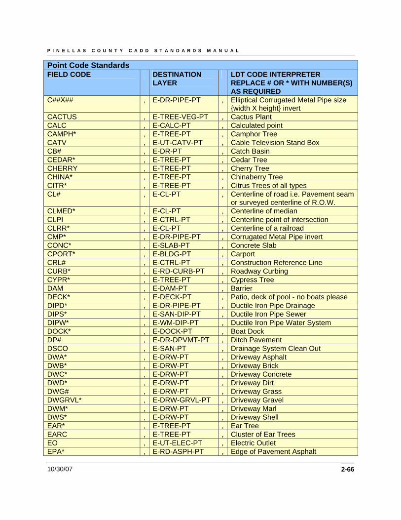
P I N E L L A S C O U N T Y C A D D S T A N D A R D S M A N U A L
10/30/07 2-66
Point Code Standards FIELD CODE DESTINATION
LAYER LDT CODE INTERPRETER
REPLACE # OR * WITH NUMBER(S) AS REQUIRED
C##X## , E-DR-PIPE-PT , Elliptical Corrugated Metal Pipe size {width X height} invert
CACTUS , E-TREE-VEG-PT , Cactus Plant CALC , E-CALC-PT , Calculated point CAMPH* , E-TREE-PT , Camphor Tree CATV , E-UT-CATV-PT , Cable Television Stand Box CB# , E-DR-PT , Catch Basin CEDAR* , E-TREE-PT , Cedar Tree CHERRY , E-TREE-PT , Cherry Tree CHINA* , E-TREE-PT , Chinaberry Tree CITR* , E-TREE-PT , Citrus Trees of all types CL# , E-CL-PT , Centerline of road i.e. Pavement seam
or surveyed centerline of R.O.W. CLMED* , E-CL-PT , Centerline of median CLPI , E-CTRL-PT , Centerline point of intersection CLRR* , E-CL-PT , Centerline of a railroad CMP* , E-DR-PIPE-PT , Corrugated Metal Pipe invert CONC* , E-SLAB-PT , Concrete Slab CPORT* , E-BLDG-PT , Carport CRL# , E-CTRL-PT , Construction Reference Line CURB* , E-RD-CURB-PT , Roadway Curbing CYPR* , E-TREE-PT , Cypress Tree DAM , E-DAM-PT , Barrier DECK* , E-DECK-PT , Patio, deck of pool - no boats please DIPD* , E-DR-PIPE-PT , Ductile Iron Pipe Drainage DIPS* , E-SAN-DIP-PT , Ductile Iron Pipe Sewer DIPW* , E-WM-DIP-PT , Ductile Iron Pipe Water System DOCK* , E-DOCK-PT , Boat Dock DP# , E-DR-DPVMT-PT , Ditch Pavement DSCO , E-SAN-PT , Drainage System Clean Out DWA* , E-DRW-PT , Driveway Asphalt DWB* , E-DRW-PT , Driveway Brick DWC* , E-DRW-PT , Driveway Concrete DWD* , E-DRW-PT , Driveway Dirt DWG# , E-DRW-PT , Driveway Grass DWGRVL* , E-DRW-GRVL-PT , Driveway Gravel DWM* , E-DRW-PT , Driveway Marl DWS* , E-DRW-PT , Driveway Shell EAR* , E-TREE-PT , Ear Tree EARC , E-TREE-PT , Cluster of Ear Trees EO , E-UT-ELEC-PT , Electric Outlet EPA* , E-RD-ASPH-PT , Edge of Pavement Asphalt
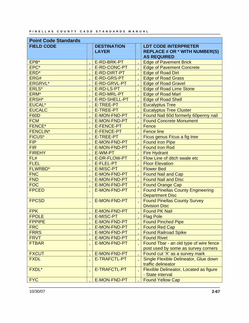
P I N E L L A S C O U N T Y C A D D S T A N D A R D S M A N U A L
10/30/07 2-67
Point Code Standards FIELD CODE DESTINATION
LAYER LDT CODE INTERPRETER
REPLACE # OR * WITH NUMBER(S) AS REQUIRED
EPB* , E-RD-BRK-PT , Edge of Pavement Brick EPC* , E-RD-CONC-PT , Edge of Pavement Concrete ERD* , E-RD-DIRT-PT , Edge of Road Dirt ERG# , E-RD-GRS-PT , Edge of Road Grass ERGRVL* , E-RD-GRVL-PT , Edge of Road Gravel ERLS* , E-RD-LS-PT , Edge of Road Lime Stone ERM* , E-RD-MRL-PT , Edge of Road Marl ERSH* , E-RD-SHELL-PT , Edge of Road Shell EUCAL* , E-TREE-PT , Eucalyptus Tree EUCALC , E-TREE-PT , Eucalyptus Tree Cluster F60D , E-MON-FND-PT , Found Nail 60d formerly 60penny nail FCM , E-MON-FND-PT , Found Concrete Monument FENCE* , E-FENCE-PT , Fence FENCLIN* , E-FENCE-PT , Fence line FICUS* , E-TREE-PT , Ficus genus Ficus a fig tree FIP , E-MON-FND-PT , Found Iron Pipe FIR , E-MON-FND-PT , Found Iron Rod FIREHY , E-WM-PT , Fire Hydrant FL# , E-DR-FLOW-PT , Flow Line of ditch swale etc FLEL , E-FLEL-PT , Floor Elevation FLWRBD* , E-MISC-PT , Flower Bed FNC , E-MON-FND-PT , Found Nail and Cap FND , E-MON-FND-PT , Found Nail and Disc FOC , E-MON-FND-PT , Found Orange Cap FPCED , E-MON-FND-PT , Found Pinellas County Engineering
Department Disc FPCSD , E-MON-FND-PT , Found Pinellas County Survey
Division Disc FPK , E-MON-FND-PT , Found PK Nail FPOLE , E-MISC-PT , Flag Pole FPPIPE , E-MON-FND-PT , Found Pinched Pipe FRC , E-MON-FND-PT , Found Red Cap FRRS , E-MON-FND-PT , Found Railroad Spike FRVT , E-MON-FND-PT , Found Rivet FTBAR , E-MON-FND-PT , Found Tbar - an old type of wire fence
post used by some as survey corners FXCUT , E-MON-FND-PT , Found cut ‘X’ as a survey mark FXDL , E-TRAFCTL-PT , Single Flexible Delineator, Glue down
traffic delineator FXDL* , E-TRAFCTL-PT , Flexible Delineator, Located as figure
- State interval FYC , E-MON-FND-PT , Found Yellow Cap
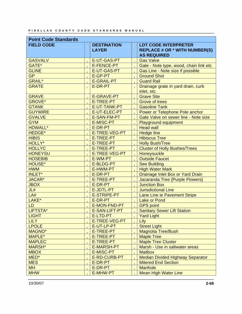
P I N E L L A S C O U N T Y C A D D S T A N D A R D S M A N U A L
10/30/07 2-68
Point Code Standards FIELD CODE DESTINATION
LAYER LDT CODE INTERPRETER
REPLACE # OR * WITH NUMBER(S) AS REQUIRED
GASVALV , E-UT-GAS-PT , Gas Valve GATE* , E-FENCE-PT , Gate - Note type, wood, chain link etc GLINE , E-UT-GAS-PT , Gas Line - Note size if possible GP , E-GP-PT , Ground Shot GRAIL* , E-GRAIL-PT , Guard Rail GRATE , E-DR-PT , Drainage grate in yard drain, curb
inlet, etc. GRAVE , E-GRAVE-PT , Grave Site GROVE* , E-TREE-PT , Grove of trees GTANK , E-UT-TANK-PT , Gasoline Tank GUYWIRE , E-UT-ELEC-PT , Power or Telephone Pole anchor GVALVE , E-SAN-FM-PT , Gate Valve on sewer line - Note size GYM , E-MISC-PT , Playground equipment HDWALL* , E-DR-PT , Head wall HEDGE* , E-TREE-VEG-PT , Hedge line HIBIS , E-TREE-PT , Hibiscus Tree HOLLY* , E-TREE-PT , Holly Bush/Tree HOLLYC , E-TREE-PT , Cluster of Holly Bushes/Trees HONEYSU , E-TREE-VEG-PT , Honeysuckle HOSEBIB , E-WM-PT , Outside Faucet HOUSE* , E-BLDG-PT , See Building HWM , E-HWM-PT , High Water Mark INLET* , E-DR-PT , Drainage Inlet Box or Yard Drain JACAR* , E-TREE-PT , Jacaranda Tree {Purple Flowers} JBOX , E-DR-PT , Junction Box JL# , E-JDTL-PT , Jurisdictional Line LA# , E-STRIPE-PT , Lane Line ie Pavement Stripe LAKE* , E-DR-PT , Lake or Pond LD , E-MON-FND-PT , GPS point LIFTSTA* , E-SAN-LIFT-PT , Sanitary Sewer Lift Station LIGHT , E-LTD-PT , Yard Light LILY , E-TREE-VEG-PT , Lily LPOLE , E-UT-LP-PT , Street Light MAGNO* , E-TREE-PT , Magnolia Tree/Bush MAPLE* , E-TREE-PT , Maple Tree MAPLEC , E-TREE-PT , Maple Tree Cluster MARSH* , E-MARSH-PT , Marsh - Use in saltwater areas MBOX , E-MISC-PT , Mailbox MED* , E-RD-CURB-PT , Median Divided Highway Separator MES , E-DR-PT , Mitered End Section MH , E-DR-PT , Manhole MHW , E-MHW-PT , Mean High Water Line
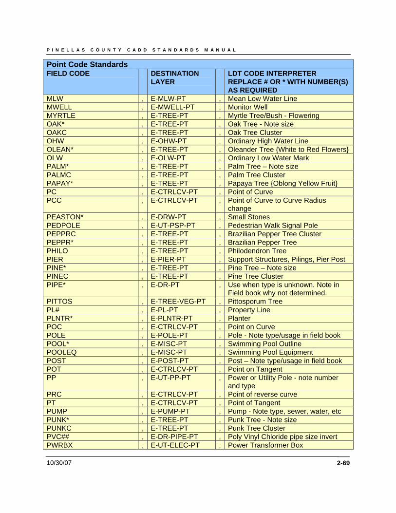
P I N E L L A S C O U N T Y C A D D S T A N D A R D S M A N U A L
10/30/07 2-69
Point Code Standards FIELD CODE DESTINATION
LAYER LDT CODE INTERPRETER
REPLACE # OR * WITH NUMBER(S) AS REQUIRED
MLW , E-MLW-PT , Mean Low Water Line MWELL , E-MWELL-PT , Monitor Well MYRTLE , E-TREE-PT , Myrtle Tree/Bush - Flowering OAK* , E-TREE-PT , Oak Tree - Note size OAKC , E-TREE-PT , Oak Tree Cluster OHW , E-OHW-PT , Ordinary High Water Line OLEAN* , E-TREE-PT , Oleander Tree {White to Red Flowers} OLW , E-OLW-PT , Ordinary Low Water Mark PALM* , E-TREE-PT , Palm Tree – Note size PALMC , E-TREE-PT , Palm Tree Cluster PAPAY* , E-TREE-PT , Papaya Tree {Oblong Yellow Fruit} PC , E-CTRLCV-PT , Point of Curve PCC , E-CTRLCV-PT , Point of Curve to Curve Radius
change PEASTON* , E-DRW-PT , Small Stones PEDPOLE , E-UT-PSP-PT , Pedestrian Walk Signal Pole PEPPRC , E-TREE-PT , Brazilian Pepper Tree Cluster PEPPR* , E-TREE-PT , Brazilian Pepper Tree PHILO , E-TREE-PT , Philodendron Tree PIER , E-PIER-PT , Support Structures, Pilings, Pier Post PINE* , E-TREE-PT , Pine Tree – Note size PINEC , E-TREE-PT , Pine Tree Cluster PIPE* , E-DR-PT , Use when type is unknown. Note in
Field book why not determined. PITTOS , E-TREE-VEG-PT , Pittosporum Tree PL# , E-PL-PT , Property Line PLNTR* , E-PLNTR-PT , Planter POC , E-CTRLCV-PT , Point on Curve POLE , E-POLE-PT , Pole - Note type/usage in field book POOL* , E-MISC-PT , Swimming Pool Outline POOLEQ , E-MISC-PT , Swimming Pool Equipment POST , E-POST-PT , Post – Note type/usage in field book POT , E-CTRLCV-PT , Point on Tangent PP , E-UT-PP-PT , Power or Utility Pole - note number
and type PRC , E-CTRLCV-PT , Point of reverse curve PT , E-CTRLCV-PT , Point of Tangent PUMP , E-PUMP-PT , Pump - Note type, sewer, water, etc PUNK* , E-TREE-PT , Punk Tree - Note size PUNKC , E-TREE-PT , Punk Tree Cluster PVC## , E-DR-PIPE-PT , Poly Vinyl Chloride pipe size invert PWRBX , E-UT-ELEC-PT , Power Transformer Box
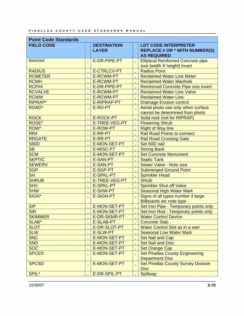
P I N E L L A S C O U N T Y C A D D S T A N D A R D S M A N U A L
10/30/07 2-70
Point Code Standards FIELD CODE DESTINATION
LAYER LDT CODE INTERPRETER
REPLACE # OR * WITH NUMBER(S) AS REQUIRED
R##X## , E-DR-PIPE-PT , Elliptical Reinforced Concrete pipe size {width X height} invert
RADIUS , E-CTRLCV-PT , Radius Point RCMETER , E-RCWM-PT , Reclaimed Water Line Meter RCMH , E-RCWM-PT , Reclaimed Water Manhole RCP## , E-DR-PIPE-PT , Reinforced Concrete Pipe size invert RCVALVE , E-RCWM-PT , Reclaimed Water Line Valve RCWM , E-RCWM-PT , Reclaimed Water Line RIPRAP* , E-RIPRAP-PT , Drainage Erosion control ROAD* , E-RD-PT , Aerial photo use only when surface
cannot be determined from photo ROCK , E-ROCK-PT , Solid rock (not for RIPRAP) ROSE* , E-TREE-VEG-PT , Flowering Shrub ROW* , E-ROW-PT , Right of Way line RR# , E-RR-PT , Rail Road Points to connect RRGATE , E-RR-PT , Rail Road Crossing Gate S60D , E-MON-SET-PT , Set 60D nail SB , E-MISC-PT , Strong Back SCM , E-MON-SET-PT , Set Concrete Monument SEPTIC , E-SAN-PT , Septic Tank SEWERV , E-SAN-PT , Sewer Valve - Note size SGP , E-SGP-PT , Submerged Ground Point SH , E-SPKL-PT , Sprinkler Head SHRUB , E-TREE-VEG-PT , Shrub SHV , E-SPKL-PT , Sprinkler Shut off Valve SHW , E-SHW-PT , Seasonal High Water Mark SIGN* , E-SIGN-PT , Signs of all types number if large
Billboards etc note type SIP , E-MON-SET-PT , Set Iron Pipe - Temporary points only SIR , E-MON-SET-PT , Set Iron Rod - Temporary points only SKIMMER , E-DR-SKMR-PT , Water Control Device SLAB* , E-SLAB-PT , Concrete Slab SLOT , E-DR-SLOT-PT , Water Control Slot as in a weir SLW , E-SLW-PT , Seasonal Low Water Mark SNC , E-MON-SET-PT , Set Nail and Cap SND , E-MON-SET-PT , Set Nail and Disc SOC , E-MON-SET-PT , Set Orange Cap SPCED , E-MON-SET-PT , Set Pinellas County Engineering
Department Disc SPCSD , E-MON-SET-PT , Set Pinellas County Survey Division
Disc SPIL* , E-DR-SPIL-PT , Spillway
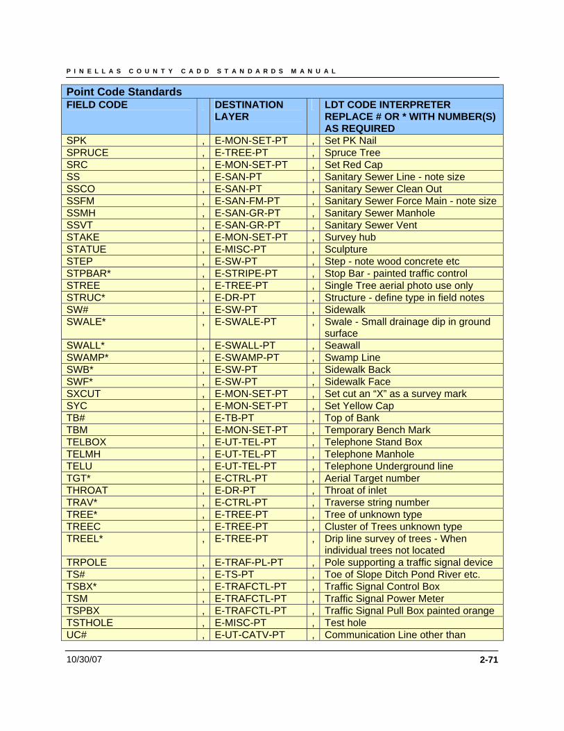
P I N E L L A S C O U N T Y C A D D S T A N D A R D S M A N U A L
10/30/07 2-71
Point Code Standards FIELD CODE DESTINATION
LAYER LDT CODE INTERPRETER
REPLACE # OR * WITH NUMBER(S) AS REQUIRED
SPK , E-MON-SET-PT , Set PK Nail SPRUCE , E-TREE-PT , Spruce Tree SRC , E-MON-SET-PT , Set Red Cap SS , E-SAN-PT , Sanitary Sewer Line - note size SSCO , E-SAN-PT , Sanitary Sewer Clean Out SSFM , E-SAN-FM-PT , Sanitary Sewer Force Main - note size SSMH , E-SAN-GR-PT , Sanitary Sewer Manhole SSVT , E-SAN-GR-PT , Sanitary Sewer Vent STAKE , E-MON-SET-PT , Survey hub STATUE , E-MISC-PT , Sculpture STEP , E-SW-PT , Step - note wood concrete etc STPBAR* , E-STRIPE-PT , Stop Bar - painted traffic control STREE , E-TREE-PT , Single Tree aerial photo use only STRUC* , E-DR-PT , Structure - define type in field notes SW# , E-SW-PT , Sidewalk SWALE* , E-SWALE-PT , Swale - Small drainage dip in ground
surface SWALL* , E-SWALL-PT , Seawall SWAMP* , E-SWAMP-PT , Swamp Line SWB* , E-SW-PT , Sidewalk Back SWF* , E-SW-PT , Sidewalk Face SXCUT , E-MON-SET-PT , Set cut an “X” as a survey mark SYC , E-MON-SET-PT , Set Yellow Cap TB# , E-TB-PT , Top of Bank TBM , E-MON-SET-PT , Temporary Bench Mark TELBOX , E-UT-TEL-PT , Telephone Stand Box TELMH , E-UT-TEL-PT , Telephone Manhole TELU , E-UT-TEL-PT , Telephone Underground line TGT* , E-CTRL-PT , Aerial Target number THROAT , E-DR-PT , Throat of inlet TRAV* , E-CTRL-PT , Traverse string number TREE* , E-TREE-PT , Tree of unknown type TREEC , E-TREE-PT , Cluster of Trees unknown type TREEL* , E-TREE-PT , Drip line survey of trees - When
individual trees not located TRPOLE , E-TRAF-PL-PT , Pole supporting a traffic signal device TS# , E-TS-PT , Toe of Slope Ditch Pond River etc. TSBX* , E-TRAFCTL-PT , Traffic Signal Control Box TSM , E-TRAFCTL-PT , Traffic Signal Power Meter TSPBX , E-TRAFCTL-PT , Traffic Signal Pull Box painted orange TSTHOLE , E-MISC-PT , Test hole UC# , E-UT-CATV-PT , Communication Line other than
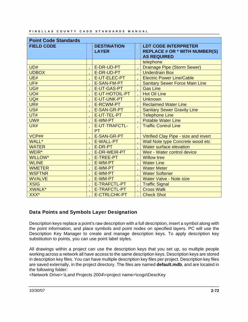
P I N E L L A S C O U N T Y C A D D S T A N D A R D S M A N U A L
10/30/07 2-72
Point Code Standards FIELD CODE DESTINATION
LAYER LDT CODE INTERPRETER
REPLACE # OR * WITH NUMBER(S) AS REQUIRED telephone
UD# , E-DR-UD-PT , Drainage Pipe (Storm Sewer) UDBOX , E-DR-UD-PT , Underdrain Box UE# , E-UT-ELEC-PT , Electric Power Line/Cable UF# , E-SAN-FM-PT , Sanitary Sewer Force Main Line UG# , E-UT-GAS-PT , Gas Line UO# , E-UT-HOTOIL-PT , Hot Oil Line UQ# , E-UT-UNK-PT , Unknown UR# , E-RCWM-PT , Reclaimed Water Line US# , E-SAN-GR-PT , Sanitary Sewer Gravity Line UT# , E-UT-TEL-PT , Telephone Line UW# , E-WM-PT , Potable Water Line UX# , E-UT-TRAFCTL-
PT , Traffic Control Line
VCP## , E-SAN-GR-PT , Vitrified Clay Pipe - size and invert WALL* , E-WALL-PT , Wall Note type Concrete wood etc WATER , E-DR-PT , Water surface elevation WEIR* , E-DR-WEIR-PT , Weir - Water control device WILLOW* , E-TREE-PT , Willow tree WLINE , E-WM-PT , Water Line WMETER , E-WM-PT , Water Meter WSFTNR , E-WM-PT , Water Softener WVALVE , E-WM-PT , Water Valve - Note size XSIG , E-TRAFCTL-PT , Traffic Signal XWALK* , E-TRAFCTL-PT , Cross Walk XXX* , E-CTRLCHK-PT , Check Shot Data Points and Symbols Layer Designation Description keys replace a point's raw description with a full description, insert a symbol along with the point information, and place symbols and point nodes on specified layers. PC will use the Description Key Manager to create and manage description keys. To apply description key substitution to points, you can use point label styles. All drawings within a project can use the description keys that you set up, so multiple people working across a network all have access to the same description keys. Description keys are stored in description key files. You can have multiple description key files per project. Description key files are saved externally, in the project directory. The files are named default.mdb, and are located in the following folder: <Network Drive>:\Land Projects 2004\<project name>\cogo\DescKey

P I N E L L A S C O U N T Y C A D D S T A N D A R D S M A N U A L
10/30/07 2-73
You can also import a project.dsc file, a previous version of a description key file from Softdesk 7 or Softdesk 8. Data Points and Symbols Layer Designation
CODE POINT LAYER SYMBOL SYMBOL LAYER
POINT ANNOTATION
ADS , E-DR-PIPE-PT , , , * ADS10 , E-DR-PIPE-PT , , , 10" ADS Inv ADS12 , E-DR-PIPE-PT , , , 12" ADS Inv ADS15 , E-DR-PIPE-PT , , , 15" ADS Inv ADS18 , E-DR-PIPE-PT , , , 18" ADS Inv ADS21 , E-DR-PIPE-PT , , , 21" ADS Inv ADS24 , E-DR-PIPE-PT , , , 24" ADS Inv ADS30 , E-DR-PIPE-PT , , , 30" ADS Inv ADS36 , E-DR-PIPE-PT , , , 36" ADS Inv ADS4 , E-DR-PIPE-PT , , , 4" ADS Inv ADS42 , E-DR-PIPE-PT , , , 42"HC ADS Inv ADS48 , E-DR-PIPE-PT , , , 48"HC ADS Inv ADS6 , E-DR-PIPE-PT , , , 6" ADS Inv ADS60 , E-DR-PIPE-PT , , , 60"HC ADS Inv ADS8 , E-DR-PIPE-PT , , , 8" ADS Inv ADSPF , E-DR-PIPE-PT , , , * ADSPF12 , E-DR-PIPE-PT , , , 12" ADSPF Inv ADSPF15 , E-DR-PIPE-PT , , , 15" ADSPF Inv ADSPF18 , E-DR-PIPE-PT , , , 18" ADSPF Inv ADSPF21 , E-DR-PIPE-PT , , , 21" ADSPF Inv ADSPF24 , E-DR-PIPE-PT , , , 24" ADSPF Inv ADSPF30 , E-DR-PIPE-PT , , , 30" ADSPF Inv ADSPF36 , E-DR-PIPE-PT , , , 36" ADSPF Inv ADSPF8 , E-DR-PIPE-PT , , , 8" ADSPF Inv ALOE* , E-TREE-VEG-PT , DT , E-TREE-
VEG , *
ARBOR , E-TREE-PT , ET , E-TREE , ARBORVITAE ASPHPAT , E-RD-ASPH-PT , , , * ASPHPAT* , E-RD-ASPH-PT , , , * AUPIN10 , E-TREE-PT , ET , E-TREE , 10" AUS PINE AUPIN11 , E-TREE-PT , ET , E-TREE , 11" AUS PINE AUPIN12 , E-TREE-PT , ET , E-TREE , 12" AUS PINE AUPIN13 , E-TREE-PT , ET , E-TREE , 13" AUS PINE AUPIN14 , E-TREE-PT , ET , E-TREE , 14" AUS PINE AUPIN15 , E-TREE-PT , ET , E-TREE , 15" AUS PINE
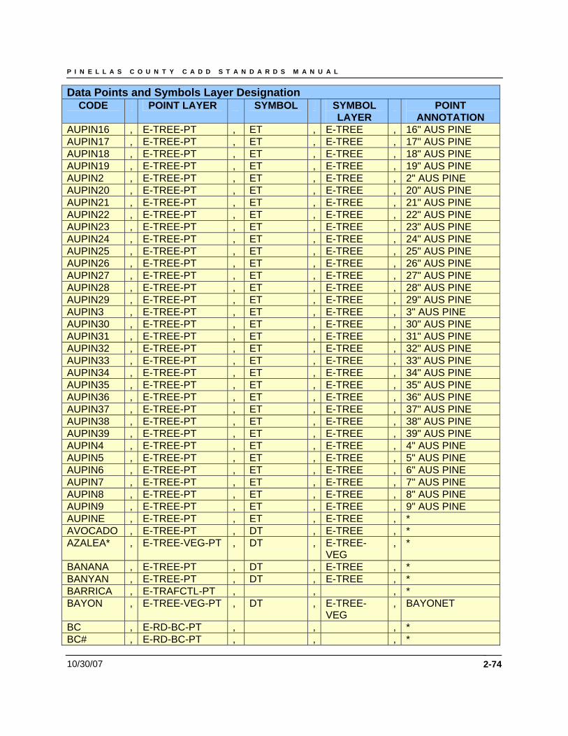
P I N E L L A S C O U N T Y C A D D S T A N D A R D S M A N U A L
10/30/07 2-74
Data Points and Symbols Layer Designation CODE POINT LAYER SYMBOL SYMBOL
LAYER POINT
ANNOTATION AUPIN16 , E-TREE-PT , ET , E-TREE , 16" AUS PINE AUPIN17 , E-TREE-PT , ET , E-TREE , 17" AUS PINE AUPIN18 , E-TREE-PT , ET , E-TREE , 18" AUS PINE AUPIN19 , E-TREE-PT , ET , E-TREE , 19" AUS PINE AUPIN2 , E-TREE-PT , ET , E-TREE , 2" AUS PINE AUPIN20 , E-TREE-PT , ET , E-TREE , 20" AUS PINE AUPIN21 , E-TREE-PT , ET , E-TREE , 21" AUS PINE AUPIN22 , E-TREE-PT , ET , E-TREE , 22" AUS PINE AUPIN23 , E-TREE-PT , ET , E-TREE , 23" AUS PINE AUPIN24 , E-TREE-PT , ET , E-TREE , 24" AUS PINE AUPIN25 , E-TREE-PT , ET , E-TREE , 25" AUS PINE AUPIN26 , E-TREE-PT , ET , E-TREE , 26" AUS PINE AUPIN27 , E-TREE-PT , ET , E-TREE , 27" AUS PINE AUPIN28 , E-TREE-PT , ET , E-TREE , 28" AUS PINE AUPIN29 , E-TREE-PT , ET , E-TREE , 29" AUS PINE AUPIN3 , E-TREE-PT , ET , E-TREE , 3" AUS PINE AUPIN30 , E-TREE-PT , ET , E-TREE , 30" AUS PINE AUPIN31 , E-TREE-PT , ET , E-TREE , 31" AUS PINE AUPIN32 , E-TREE-PT , ET , E-TREE , 32" AUS PINE AUPIN33 , E-TREE-PT , ET , E-TREE , 33" AUS PINE AUPIN34 , E-TREE-PT , ET , E-TREE , 34" AUS PINE AUPIN35 , E-TREE-PT , ET , E-TREE , 35" AUS PINE AUPIN36 , E-TREE-PT , ET , E-TREE , 36" AUS PINE AUPIN37 , E-TREE-PT , ET , E-TREE , 37" AUS PINE AUPIN38 , E-TREE-PT , ET , E-TREE , 38" AUS PINE AUPIN39 , E-TREE-PT , ET , E-TREE , 39" AUS PINE AUPIN4 , E-TREE-PT , ET , E-TREE , 4" AUS PINE AUPIN5 , E-TREE-PT , ET , E-TREE , 5" AUS PINE AUPIN6 , E-TREE-PT , ET , E-TREE , 6" AUS PINE AUPIN7 , E-TREE-PT , ET , E-TREE , 7" AUS PINE AUPIN8 , E-TREE-PT , ET , E-TREE , 8" AUS PINE AUPIN9 , E-TREE-PT , ET , E-TREE , 9" AUS PINE AUPINE , E-TREE-PT , ET , E-TREE , * AVOCADO , E-TREE-PT , DT , E-TREE , * AZALEA* , E-TREE-VEG-PT , DT , E-TREE-
VEG , *
BANANA , E-TREE-PT , DT , E-TREE , * BANYAN , E-TREE-PT , DT , E-TREE , * BARRICA , E-TRAFCTL-PT , , , * BAYON , E-TREE-VEG-PT , DT , E-TREE-
VEG , BAYONET
BC , E-RD-BC-PT , , , * BC# , E-RD-BC-PT , , , *
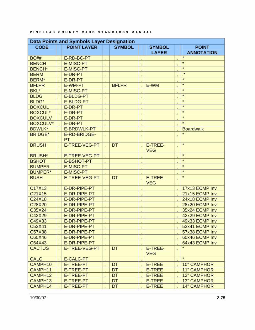
P I N E L L A S C O U N T Y C A D D S T A N D A R D S M A N U A L
10/30/07 2-75
Data Points and Symbols Layer Designation CODE POINT LAYER SYMBOL SYMBOL
LAYER POINT
ANNOTATION BC## , E-RD-BC-PT , , , * BENCH , E-MISC-PT , , , * BENCH* , E-MISC-PT , , , * BERM , E-DR-PT , , , ,* BERM* , E-DR-PT , , , * BFLPR , E-WM-PT , BFLPR , E-WM , * BKL* , E-MISC-PT , , , * BLDG , E-BLDG-PT , , , * BLDG* , E-BLDG-PT , , , * BOXCUL , E-DR-PT , , , * BOXCUL* , E-DR-PT , , , * BOXCULV , E-DR-PT , , , * BOXCULV* , E-DR-PT , , , * BDWLK* , E-BRDWLK-PT , , , Boardwalk BRIDGE* , E-RD-BRIDGE-
PT , , , *
BRUSH , E-TREE-VEG-PT , DT , E-TREE-VEG
, *
BRUSH* , E-TREE-VEG-PT , , , * BSHOT , E-BSHOT-PT , , , * BUMPER , E-MISC-PT , , , * BUMPER* , E-MISC-PT , , , * BUSH , E-TREE-VEG-PT , DT , E-TREE-
VEG , *
C17X13 , E-DR-PIPE-PT , , , 17x13 ECMP Inv C21X15 , E-DR-PIPE-PT , , , 21x15 ECMP Inv C24X18 , E-DR-PIPE-PT , , , 24x18 ECMP Inv C28X20 , E-DR-PIPE-PT , , , 28x20 ECMP Inv C35X24 , E-DR-PIPE-PT , , , 35x24 ECMP Inv C42X29 , E-DR-PIPE-PT , , , 42x29 ECMP Inv C49X33 , E-DR-PIPE-PT , , , 49x33 ECMP Inv C53X41 , E-DR-PIPE-PT , , , 53x41 ECMP Inv C57X38 , E-DR-PIPE-PT , , , 57x38 ECMP Inv C60X46 , E-DR-PIPE-PT , , , 60x46 ECMP Inv C64X43 , E-DR-PIPE-PT , , , 64x43 ECMP Inv CACTUS , E-TREE-VEG-PT , DT , E-TREE-
VEG , *
CALC , E-CALC-PT , , , * CAMPH10 , E-TREE-PT , DT , E-TREE , 10" CAMPHOR CAMPH11 , E-TREE-PT , DT , E-TREE , 11" CAMPHOR CAMPH12 , E-TREE-PT , DT , E-TREE , 12" CAMPHOR CAMPH13 , E-TREE-PT , DT , E-TREE , 13" CAMPHOR CAMPH14 , E-TREE-PT , DT , E-TREE , 14" CAMPHOR
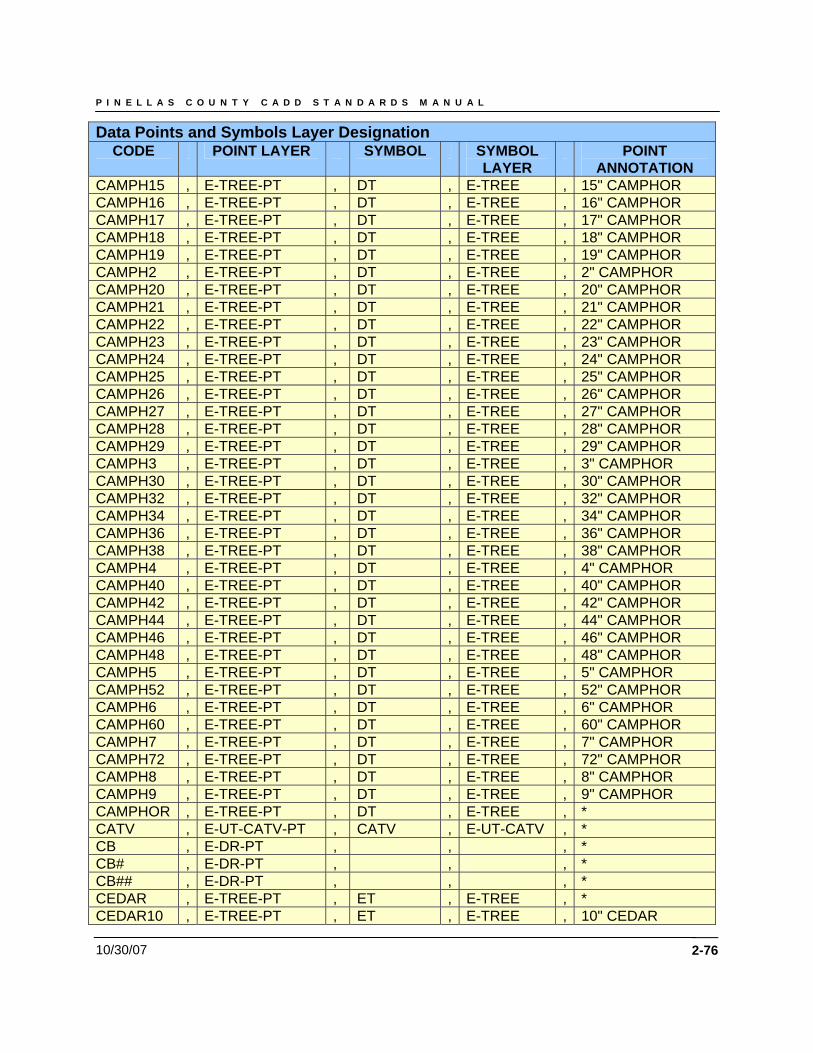
P I N E L L A S C O U N T Y C A D D S T A N D A R D S M A N U A L
10/30/07 2-76
Data Points and Symbols Layer Designation CODE POINT LAYER SYMBOL SYMBOL
LAYER POINT
ANNOTATION CAMPH15 , E-TREE-PT , DT , E-TREE , 15" CAMPHOR CAMPH16 , E-TREE-PT , DT , E-TREE , 16" CAMPHOR CAMPH17 , E-TREE-PT , DT , E-TREE , 17" CAMPHOR CAMPH18 , E-TREE-PT , DT , E-TREE , 18" CAMPHOR CAMPH19 , E-TREE-PT , DT , E-TREE , 19" CAMPHOR CAMPH2 , E-TREE-PT , DT , E-TREE , 2" CAMPHOR CAMPH20 , E-TREE-PT , DT , E-TREE , 20" CAMPHOR CAMPH21 , E-TREE-PT , DT , E-TREE , 21" CAMPHOR CAMPH22 , E-TREE-PT , DT , E-TREE , 22" CAMPHOR CAMPH23 , E-TREE-PT , DT , E-TREE , 23" CAMPHOR CAMPH24 , E-TREE-PT , DT , E-TREE , 24" CAMPHOR CAMPH25 , E-TREE-PT , DT , E-TREE , 25" CAMPHOR CAMPH26 , E-TREE-PT , DT , E-TREE , 26" CAMPHOR CAMPH27 , E-TREE-PT , DT , E-TREE , 27" CAMPHOR CAMPH28 , E-TREE-PT , DT , E-TREE , 28" CAMPHOR CAMPH29 , E-TREE-PT , DT , E-TREE , 29" CAMPHOR CAMPH3 , E-TREE-PT , DT , E-TREE , 3" CAMPHOR CAMPH30 , E-TREE-PT , DT , E-TREE , 30" CAMPHOR CAMPH32 , E-TREE-PT , DT , E-TREE , 32" CAMPHOR CAMPH34 , E-TREE-PT , DT , E-TREE , 34" CAMPHOR CAMPH36 , E-TREE-PT , DT , E-TREE , 36" CAMPHOR CAMPH38 , E-TREE-PT , DT , E-TREE , 38" CAMPHOR CAMPH4 , E-TREE-PT , DT , E-TREE , 4" CAMPHOR CAMPH40 , E-TREE-PT , DT , E-TREE , 40" CAMPHOR CAMPH42 , E-TREE-PT , DT , E-TREE , 42" CAMPHOR CAMPH44 , E-TREE-PT , DT , E-TREE , 44" CAMPHOR CAMPH46 , E-TREE-PT , DT , E-TREE , 46" CAMPHOR CAMPH48 , E-TREE-PT , DT , E-TREE , 48" CAMPHOR CAMPH5 , E-TREE-PT , DT , E-TREE , 5" CAMPHOR CAMPH52 , E-TREE-PT , DT , E-TREE , 52" CAMPHOR CAMPH6 , E-TREE-PT , DT , E-TREE , 6" CAMPHOR CAMPH60 , E-TREE-PT , DT , E-TREE , 60" CAMPHOR CAMPH7 , E-TREE-PT , DT , E-TREE , 7" CAMPHOR CAMPH72 , E-TREE-PT , DT , E-TREE , 72" CAMPHOR CAMPH8 , E-TREE-PT , DT , E-TREE , 8" CAMPHOR CAMPH9 , E-TREE-PT , DT , E-TREE , 9" CAMPHOR CAMPHOR , E-TREE-PT , DT , E-TREE , * CATV , E-UT-CATV-PT , CATV , E-UT-CATV , * CB , E-DR-PT , , , * CB# , E-DR-PT , , , * CB## , E-DR-PT , , , * CEDAR , E-TREE-PT , ET , E-TREE , * CEDAR10 , E-TREE-PT , ET , E-TREE , 10" CEDAR
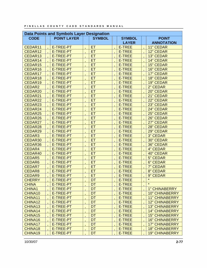
P I N E L L A S C O U N T Y C A D D S T A N D A R D S M A N U A L
10/30/07 2-77
Data Points and Symbols Layer Designation CODE POINT LAYER SYMBOL SYMBOL
LAYER POINT
ANNOTATION CEDAR11 , E-TREE-PT , ET , E-TREE , 11" CEDAR CEDAR12 , E-TREE-PT , ET , E-TREE , 12" CEDAR CEDAR13 , E-TREE-PT , ET , E-TREE , 13" CEDAR CEDAR14 , E-TREE-PT , ET , E-TREE , 14" CEDAR CEDAR15 , E-TREE-PT , ET , E-TREE , 15" CEDAR CEDAR16 , E-TREE-PT , ET , E-TREE , 16" CEDAR CEDAR17 , E-TREE-PT , ET , E-TREE , 17" CEDAR CEDAR18 , E-TREE-PT , ET , E-TREE , 18" CEDAR CEDAR19 , E-TREE-PT , ET , E-TREE , 19" CEDAR CEDAR2 , E-TREE-PT , ET , E-TREE , 2" CEDAR CEDAR20 , E-TREE-PT , ET , E-TREE , 20" CEDAR CEDAR21 , E-TREE-PT , ET , E-TREE , 21" CEDAR CEDAR22 , E-TREE-PT , ET , E-TREE , 22" CEDAR CEDAR23 , E-TREE-PT , ET , E-TREE , 23" CEDAR CEDAR24 , E-TREE-PT , ET , E-TREE , 24" CEDAR CEDAR25 , E-TREE-PT , ET , E-TREE , 25" CEDAR CEDAR26 , E-TREE-PT , ET , E-TREE , 26" CEDAR CEDAR27 , E-TREE-PT , ET , E-TREE , 27" CEDAR CEDAR28 , E-TREE-PT , ET , E-TREE , 28" CEDAR CEDAR29 , E-TREE-PT , ET , E-TREE , 29" CEDAR CEDAR3 , E-TREE-PT , ET , E-TREE , 3" CEDAR CEDAR30 , E-TREE-PT , ET , E-TREE , 30" CEDAR CEDAR36 , E-TREE-PT , ET , E-TREE , 36" CEDAR CEDAR4 , E-TREE-PT , ET , E-TREE , 4" CEDAR CEDAR40 , E-TREE-PT , ET , E-TREE , 40" CEDAR CEDAR5 , E-TREE-PT , ET , E-TREE , 5" CEDAR CEDAR6 , E-TREE-PT , ET , E-TREE , 6" CEDAR CEDAR7 , E-TREE-PT , ET , E-TREE , 7" CEDAR CEDAR8 , E-TREE-PT , ET , E-TREE , 8" CEDAR CEDAR9 , E-TREE-PT , ET , E-TREE , 9" CEDAR CHERRY , E-TREE-PT , DT , E-TREE , * CHINA , E-TREE-PT , DT , E-TREE , * CHINA1 , E-TREE-PT , DT , E-TREE , 1" CHINABERRY CHINA10 , E-TREE-PT , DT , E-TREE , 10" CHINABERRY CHINA11 , E-TREE-PT , DT , E-TREE , 11" CHINABERRY CHINA12 , E-TREE-PT , DT , E-TREE , 12" CHINABERRY CHINA13 , E-TREE-PT , DT , E-TREE , 13" CHINABERRY CHINA14 , E-TREE-PT , DT , E-TREE , 14" CHINABERRY CHINA15 , E-TREE-PT , DT , E-TREE , 15" CHINABERRY CHINA16 , E-TREE-PT , DT , E-TREE , 16" CHINABERRY CHINA17 , E-TREE-PT , DT , E-TREE , 17" CHINABERRY CHINA18 , E-TREE-PT , DT , E-TREE , 18" CHINABERRY CHINA19 , E-TREE-PT , DT , E-TREE , 19" CHINABERRY
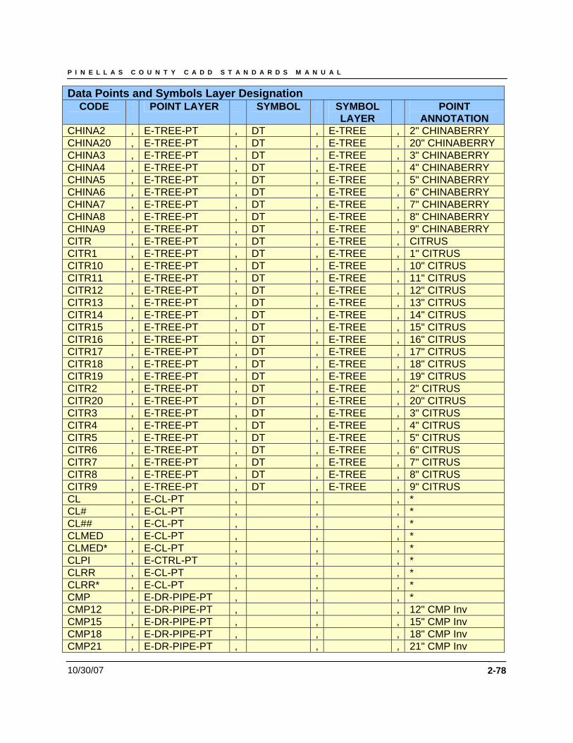
P I N E L L A S C O U N T Y C A D D S T A N D A R D S M A N U A L
10/30/07 2-78
Data Points and Symbols Layer Designation CODE POINT LAYER SYMBOL SYMBOL
LAYER POINT
ANNOTATION CHINA2 , E-TREE-PT , DT , E-TREE , 2" CHINABERRY CHINA20 , E-TREE-PT , DT , E-TREE , 20" CHINABERRY CHINA3 , E-TREE-PT , DT , E-TREE , 3" CHINABERRY CHINA4 , E-TREE-PT , DT , E-TREE , 4" CHINABERRY CHINA5 , E-TREE-PT , DT , E-TREE , 5" CHINABERRY CHINA6 , E-TREE-PT , DT , E-TREE , 6" CHINABERRY CHINA7 , E-TREE-PT , DT , E-TREE , 7" CHINABERRY CHINA8 , E-TREE-PT , DT , E-TREE , 8" CHINABERRY CHINA9 , E-TREE-PT , DT , E-TREE , 9" CHINABERRY CITR , E-TREE-PT , DT , E-TREE , CITRUS CITR1 , E-TREE-PT , DT , E-TREE , 1" CITRUS CITR10 , E-TREE-PT , DT , E-TREE , 10" CITRUS CITR11 , E-TREE-PT , DT , E-TREE , 11" CITRUS CITR12 , E-TREE-PT , DT , E-TREE , 12" CITRUS CITR13 , E-TREE-PT , DT , E-TREE , 13" CITRUS CITR14 , E-TREE-PT , DT , E-TREE , 14" CITRUS CITR15 , E-TREE-PT , DT , E-TREE , 15" CITRUS CITR16 , E-TREE-PT , DT , E-TREE , 16" CITRUS CITR17 , E-TREE-PT , DT , E-TREE , 17" CITRUS CITR18 , E-TREE-PT , DT , E-TREE , 18" CITRUS CITR19 , E-TREE-PT , DT , E-TREE , 19" CITRUS CITR2 , E-TREE-PT , DT , E-TREE , 2" CITRUS CITR20 , E-TREE-PT , DT , E-TREE , 20" CITRUS CITR3 , E-TREE-PT , DT , E-TREE , 3" CITRUS CITR4 , E-TREE-PT , DT , E-TREE , 4" CITRUS CITR5 , E-TREE-PT , DT , E-TREE , 5" CITRUS CITR6 , E-TREE-PT , DT , E-TREE , 6" CITRUS CITR7 , E-TREE-PT , DT , E-TREE , 7" CITRUS CITR8 , E-TREE-PT , DT , E-TREE , 8" CITRUS CITR9 , E-TREE-PT , DT , E-TREE , 9" CITRUS CL , E-CL-PT , , , * CL# , E-CL-PT , , , * CL## , E-CL-PT , , , * CLMED , E-CL-PT , , , * CLMED* , E-CL-PT , , , * CLPI , E-CTRL-PT , , , * CLRR , E-CL-PT , , , * CLRR* , E-CL-PT , , , * CMP , E-DR-PIPE-PT , , , * CMP12 , E-DR-PIPE-PT , , , 12" CMP Inv CMP15 , E-DR-PIPE-PT , , , 15" CMP Inv CMP18 , E-DR-PIPE-PT , , , 18" CMP Inv CMP21 , E-DR-PIPE-PT , , , 21" CMP Inv
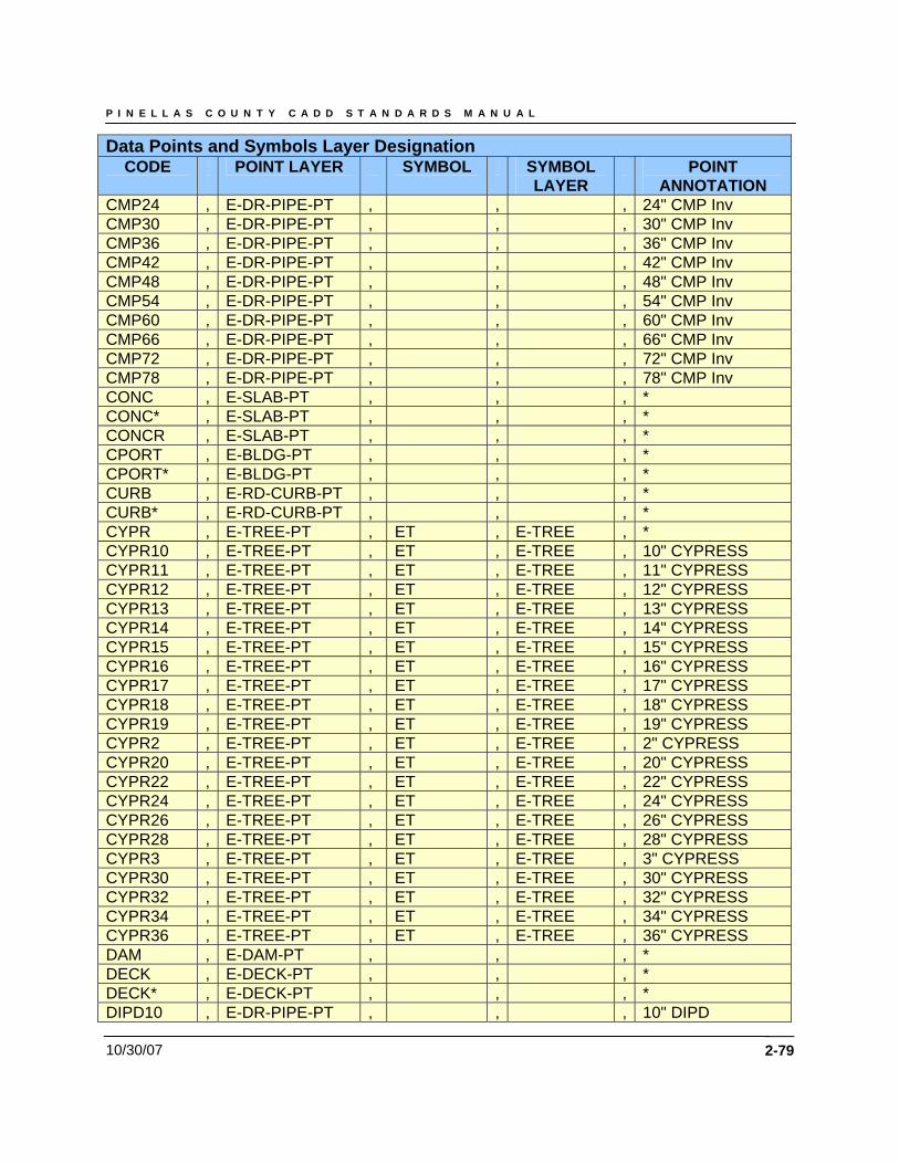
P I N E L L A S C O U N T Y C A D D S T A N D A R D S M A N U A L
10/30/07 2-79
Data Points and Symbols Layer Designation CODE POINT LAYER SYMBOL SYMBOL
LAYER POINT
ANNOTATION CMP24 , E-DR-PIPE-PT , , , 24" CMP Inv CMP30 , E-DR-PIPE-PT , , , 30" CMP Inv CMP36 , E-DR-PIPE-PT , , , 36" CMP Inv CMP42 , E-DR-PIPE-PT , , , 42" CMP Inv CMP48 , E-DR-PIPE-PT , , , 48" CMP Inv CMP54 , E-DR-PIPE-PT , , , 54" CMP Inv CMP60 , E-DR-PIPE-PT , , , 60" CMP Inv CMP66 , E-DR-PIPE-PT , , , 66" CMP Inv CMP72 , E-DR-PIPE-PT , , , 72" CMP Inv CMP78 , E-DR-PIPE-PT , , , 78" CMP Inv CONC , E-SLAB-PT , , , * CONC* , E-SLAB-PT , , , * CONCR , E-SLAB-PT , , , * CPORT , E-BLDG-PT , , , * CPORT* , E-BLDG-PT , , , * CURB , E-RD-CURB-PT , , , * CURB* , E-RD-CURB-PT , , , * CYPR , E-TREE-PT , ET , E-TREE , * CYPR10 , E-TREE-PT , ET , E-TREE , 10" CYPRESS CYPR11 , E-TREE-PT , ET , E-TREE , 11" CYPRESS CYPR12 , E-TREE-PT , ET , E-TREE , 12" CYPRESS CYPR13 , E-TREE-PT , ET , E-TREE , 13" CYPRESS CYPR14 , E-TREE-PT , ET , E-TREE , 14" CYPRESS CYPR15 , E-TREE-PT , ET , E-TREE , 15" CYPRESS CYPR16 , E-TREE-PT , ET , E-TREE , 16" CYPRESS CYPR17 , E-TREE-PT , ET , E-TREE , 17" CYPRESS CYPR18 , E-TREE-PT , ET , E-TREE , 18" CYPRESS CYPR19 , E-TREE-PT , ET , E-TREE , 19" CYPRESS CYPR2 , E-TREE-PT , ET , E-TREE , 2" CYPRESS CYPR20 , E-TREE-PT , ET , E-TREE , 20" CYPRESS CYPR22 , E-TREE-PT , ET , E-TREE , 22" CYPRESS CYPR24 , E-TREE-PT , ET , E-TREE , 24" CYPRESS CYPR26 , E-TREE-PT , ET , E-TREE , 26" CYPRESS CYPR28 , E-TREE-PT , ET , E-TREE , 28" CYPRESS CYPR3 , E-TREE-PT , ET , E-TREE , 3" CYPRESS CYPR30 , E-TREE-PT , ET , E-TREE , 30" CYPRESS CYPR32 , E-TREE-PT , ET , E-TREE , 32" CYPRESS CYPR34 , E-TREE-PT , ET , E-TREE , 34" CYPRESS CYPR36 , E-TREE-PT , ET , E-TREE , 36" CYPRESS DAM , E-DAM-PT , , , * DECK , E-DECK-PT , , , * DECK* , E-DECK-PT , , , * DIPD10 , E-DR-PIPE-PT , , , 10" DIPD
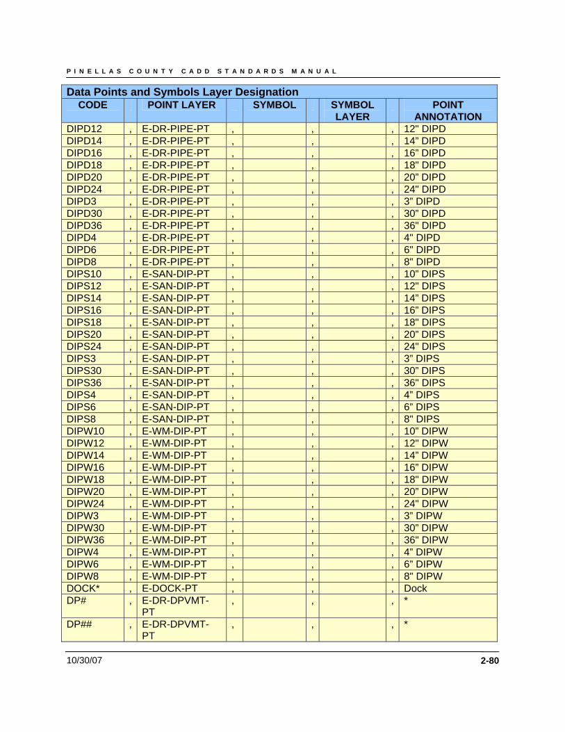
P I N E L L A S C O U N T Y C A D D S T A N D A R D S M A N U A L
10/30/07 2-80
Data Points and Symbols Layer Designation CODE POINT LAYER SYMBOL SYMBOL
LAYER POINT
ANNOTATION DIPD12 , E-DR-PIPE-PT , , , 12" DIPD DIPD14 , E-DR-PIPE-PT , , , 14” DIPD DIPD16 , E-DR-PIPE-PT , , , 16” DIPD DIPD18 , E-DR-PIPE-PT , , , 18" DIPD DIPD20 , E-DR-PIPE-PT , , , 20” DIPD DIPD24 , E-DR-PIPE-PT , , , 24" DIPD DIPD3 , E-DR-PIPE-PT , , , 3” DIPD DIPD30 , E-DR-PIPE-PT , , , 30” DIPD DIPD36 , E-DR-PIPE-PT , , , 36" DIPD DIPD4 , E-DR-PIPE-PT , , , 4" DIPD DIPD6 , E-DR-PIPE-PT , , , 6" DIPD DIPD8 , E-DR-PIPE-PT , , , 8" DIPD DIPS10 , E-SAN-DIP-PT , , , 10” DIPS DIPS12 , E-SAN-DIP-PT , , , 12" DIPS DIPS14 , E-SAN-DIP-PT , , , 14” DIPS DIPS16 , E-SAN-DIP-PT , , , 16” DIPS DIPS18 , E-SAN-DIP-PT , , , 18" DIPS DIPS20 , E-SAN-DIP-PT , , , 20” DIPS DIPS24 , E-SAN-DIP-PT , , , 24" DIPS DIPS3 , E-SAN-DIP-PT , , , 3” DIPS DIPS30 , E-SAN-DIP-PT , , , 30” DIPS DIPS36 , E-SAN-DIP-PT , , , 36" DIPS DIPS4 , E-SAN-DIP-PT , , , 4” DIPS DIPS6 , E-SAN-DIP-PT , , , 6” DIPS DIPS8 , E-SAN-DIP-PT , , , 8" DIPS DIPW10 , E-WM-DIP-PT , , , 10” DIPW DIPW12 , E-WM-DIP-PT , , , 12" DIPW DIPW14 , E-WM-DIP-PT , , , 14” DIPW DIPW16 , E-WM-DIP-PT , , , 16” DIPW DIPW18 , E-WM-DIP-PT , , , 18" DIPW DIPW20 , E-WM-DIP-PT , , , 20” DIPW DIPW24 , E-WM-DIP-PT , , , 24" DIPW DIPW3 , E-WM-DIP-PT , , , 3” DIPW DIPW30 , E-WM-DIP-PT , , , 30” DIPW DIPW36 , E-WM-DIP-PT , , , 36" DIPW DIPW4 , E-WM-DIP-PT , , , 4” DIPW DIPW6 , E-WM-DIP-PT , , , 6” DIPW DIPW8 , E-WM-DIP-PT , , , 8" DIPW DOCK* , E-DOCK-PT , , , Dock DP# , E-DR-DPVMT-
PT , , , *
DP## , E-DR-DPVMT-PT
, , , *
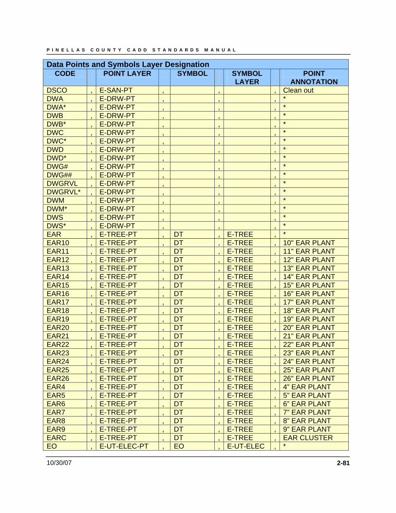
P I N E L L A S C O U N T Y C A D D S T A N D A R D S M A N U A L
10/30/07 2-81
Data Points and Symbols Layer Designation CODE POINT LAYER SYMBOL SYMBOL
LAYER POINT
ANNOTATION DSCO , E-SAN-PT , , , Clean out DWA , E-DRW-PT , , , * DWA* , E-DRW-PT , , , * DWB , E-DRW-PT , , , * DWB* , E-DRW-PT , , , * DWC , E-DRW-PT , , , * DWC* , E-DRW-PT , , , * DWD , E-DRW-PT , , , * DWD* , E-DRW-PT , , , * DWG# , E-DRW-PT , , , * DWG## , E-DRW-PT , , , * DWGRVL , E-DRW-PT , , , * DWGRVL* , E-DRW-PT , , , * DWM , E-DRW-PT , , , * DWM* , E-DRW-PT , , , * DWS , E-DRW-PT , , , * DWS* , E-DRW-PT , , , * EAR , E-TREE-PT , DT , E-TREE , * EAR10 , E-TREE-PT , DT , E-TREE , 10" EAR PLANT EAR11 , E-TREE-PT , DT , E-TREE , 11" EAR PLANT EAR12 , E-TREE-PT , DT , E-TREE , 12" EAR PLANT EAR13 , E-TREE-PT , DT , E-TREE , 13" EAR PLANT EAR14 , E-TREE-PT , DT , E-TREE , 14" EAR PLANT EAR15 , E-TREE-PT , DT , E-TREE , 15" EAR PLANT EAR16 , E-TREE-PT , DT , E-TREE , 16" EAR PLANT EAR17 , E-TREE-PT , DT , E-TREE , 17" EAR PLANT EAR18 , E-TREE-PT , DT , E-TREE , 18" EAR PLANT EAR19 , E-TREE-PT , DT , E-TREE , 19" EAR PLANT EAR20 , E-TREE-PT , DT , E-TREE , 20" EAR PLANT EAR21 , E-TREE-PT , DT , E-TREE , 21" EAR PLANT EAR22 , E-TREE-PT , DT , E-TREE , 22" EAR PLANT EAR23 , E-TREE-PT , DT , E-TREE , 23" EAR PLANT EAR24 , E-TREE-PT , DT , E-TREE , 24" EAR PLANT EAR25 , E-TREE-PT , DT , E-TREE , 25" EAR PLANT EAR26 , E-TREE-PT , DT , E-TREE , 26" EAR PLANT EAR4 , E-TREE-PT , DT , E-TREE , 4” EAR PLANT EAR5 , E-TREE-PT , DT , E-TREE , 5” EAR PLANT EAR6 , E-TREE-PT , DT , E-TREE , 6” EAR PLANT EAR7 , E-TREE-PT , DT , E-TREE , 7” EAR PLANT EAR8 , E-TREE-PT , DT , E-TREE , 8” EAR PLANT EAR9 , E-TREE-PT , DT , E-TREE , 9” EAR PLANT EARC , E-TREE-PT , DT , E-TREE , EAR CLUSTER EO , E-UT-ELEC-PT , EO , E-UT-ELEC , *
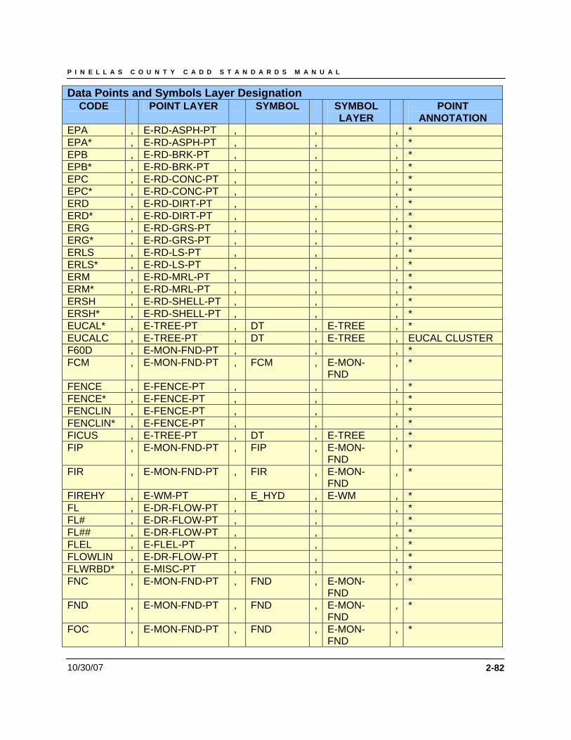
P I N E L L A S C O U N T Y C A D D S T A N D A R D S M A N U A L
10/30/07 2-82
Data Points and Symbols Layer Designation CODE POINT LAYER SYMBOL SYMBOL
LAYER POINT
ANNOTATION EPA , E-RD-ASPH-PT , , , * EPA* , E-RD-ASPH-PT , , , * EPB , E-RD-BRK-PT , , , * EPB* , E-RD-BRK-PT , , , * EPC , E-RD-CONC-PT , , , * EPC* , E-RD-CONC-PT , , , * ERD , E-RD-DIRT-PT , , , * ERD* , E-RD-DIRT-PT , , , * ERG , E-RD-GRS-PT , , , * ERG* , E-RD-GRS-PT , , , * ERLS , E-RD-LS-PT , , , * ERLS* , E-RD-LS-PT , , , * ERM , E-RD-MRL-PT , , , * ERM* , E-RD-MRL-PT , , , * ERSH , E-RD-SHELL-PT , , , * ERSH* , E-RD-SHELL-PT , , , * EUCAL* , E-TREE-PT , DT , E-TREE , * EUCALC , E-TREE-PT , DT , E-TREE , EUCAL CLUSTER F60D , E-MON-FND-PT , , , * FCM , E-MON-FND-PT , FCM , E-MON-
FND , *
FENCE , E-FENCE-PT , , , * FENCE* , E-FENCE-PT , , , * FENCLIN , E-FENCE-PT , , , * FENCLIN* , E-FENCE-PT , , , * FICUS , E-TREE-PT , DT , E-TREE , * FIP , E-MON-FND-PT , FIP , E-MON-
FND , *
FIR , E-MON-FND-PT , FIR , E-MON-FND
, *
FIREHY , E-WM-PT , E_HYD , E-WM , * FL , E-DR-FLOW-PT , , , * FL# , E-DR-FLOW-PT , , , * FL## , E-DR-FLOW-PT , , , * FLEL , E-FLEL-PT , , , * FLOWLIN , E-DR-FLOW-PT , , , * FLWRBD* , E-MISC-PT , , , * FNC , E-MON-FND-PT , FND , E-MON-
FND , *
FND , E-MON-FND-PT , FND , E-MON-FND
, *
FOC , E-MON-FND-PT , FND , E-MON-FND
, *
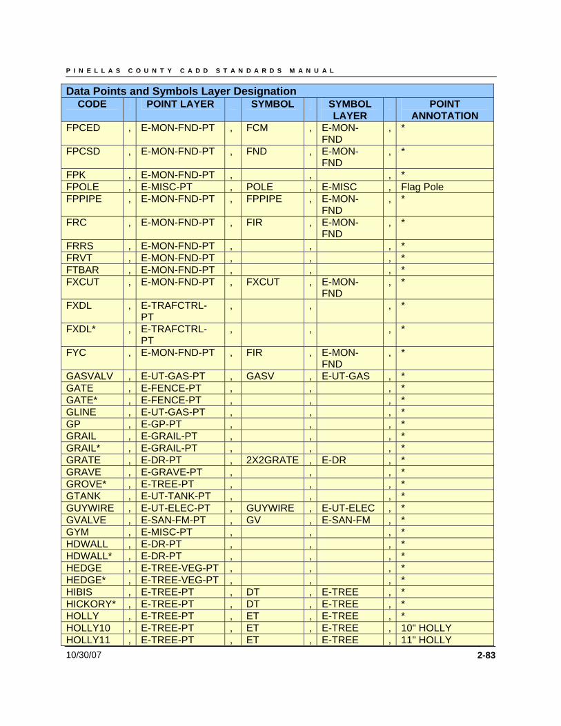
P I N E L L A S C O U N T Y C A D D S T A N D A R D S M A N U A L
10/30/07 2-83
Data Points and Symbols Layer Designation CODE POINT LAYER SYMBOL SYMBOL
LAYER POINT
ANNOTATION FPCED , E-MON-FND-PT , FCM , E-MON-
FND , *
FPCSD , E-MON-FND-PT , FND , E-MON-FND
, *
FPK , E-MON-FND-PT , , , * FPOLE , E-MISC-PT , POLE , E-MISC , Flag Pole FPPIPE , E-MON-FND-PT , FPPIPE , E-MON-
FND , *
FRC , E-MON-FND-PT , FIR , E-MON-FND
, *
FRRS , E-MON-FND-PT , , , * FRVT , E-MON-FND-PT , , , * FTBAR , E-MON-FND-PT , , , * FXCUT , E-MON-FND-PT , FXCUT , E-MON-
FND , *
FXDL , E-TRAFCTRL-PT
, , , *
FXDL* , E-TRAFCTRL-PT
, , , *
FYC , E-MON-FND-PT , FIR , E-MON-FND
, *
GASVALV , E-UT-GAS-PT , GASV , E-UT-GAS , * GATE , E-FENCE-PT , , , * GATE* , E-FENCE-PT , , , * GLINE , E-UT-GAS-PT , , , * GP , E-GP-PT , , , * GRAIL , E-GRAIL-PT , , , * GRAIL* , E-GRAIL-PT , , , * GRATE , E-DR-PT , 2X2GRATE , E-DR , * GRAVE , E-GRAVE-PT , , , * GROVE* , E-TREE-PT , , , * GTANK , E-UT-TANK-PT , , , * GUYWIRE , E-UT-ELEC-PT , GUYWIRE , E-UT-ELEC , * GVALVE , E-SAN-FM-PT , GV , E-SAN-FM , * GYM , E-MISC-PT , , , * HDWALL , E-DR-PT , , , * HDWALL* , E-DR-PT , , , * HEDGE , E-TREE-VEG-PT , , , * HEDGE* , E-TREE-VEG-PT , , , * HIBIS , E-TREE-PT , DT , E-TREE , * HICKORY* , E-TREE-PT , DT , E-TREE , * HOLLY , E-TREE-PT , ET , E-TREE , * HOLLY10 , E-TREE-PT , ET , E-TREE , 10" HOLLY HOLLY11 , E-TREE-PT , ET , E-TREE , 11" HOLLY
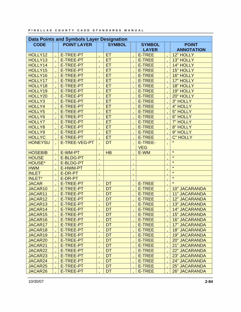
P I N E L L A S C O U N T Y C A D D S T A N D A R D S M A N U A L
10/30/07 2-84
Data Points and Symbols Layer Designation CODE POINT LAYER SYMBOL SYMBOL
LAYER POINT
ANNOTATION HOLLY12 , E-TREE-PT , ET , E-TREE , 12" HOLLY HOLLY13 , E-TREE-PT , ET , E-TREE , 13" HOLLY HOLLY14 , E-TREE-PT , ET , E-TREE , 14" HOLLY HOLLY15 , E-TREE-PT , ET , E-TREE , 15" HOLLY HOLLY16 , E-TREE-PT , ET , E-TREE , 16" HOLLY HOLLY17 , E-TREE-PT , ET , E-TREE , 17" HOLLY HOLLY18 , E-TREE-PT , ET , E-TREE , 18" HOLLY HOLLY19 , E-TREE-PT , ET , E-TREE , 19" HOLLY HOLLY20 , E-TREE-PT , ET , E-TREE , 20" HOLLY HOLLY3 , E-TREE-PT , ET , E-TREE , 3" HOLLY HOLLY4 , E-TREE-PT , ET , E-TREE , 4" HOLLY HOLLY5 , E-TREE-PT , ET , E-TREE , 5" HOLLY HOLLY6 , E-TREE-PT , ET , E-TREE , 6" HOLLY HOLLY7 , E-TREE-PT , ET , E-TREE , 7" HOLLY HOLLY8 , E-TREE-PT , ET , E-TREE , 8" HOLLY HOLLY9 , E-TREE-PT , ET , E-TREE , 9" HOLLY HOLLYC , E-TREE-PT , ET , E-TREE , C" HOLLY HONEYSU , E-TREE-VEG-PT , DT , E-TREE-
VEG , *
HOSEBIB , E-WM-PT , HB , E-WM , * HOUSE , E-BLDG-PT , , , * HOUSE* , E-BLDG-PT , , , * HWM , E-HWM-PT , , , * INLET , E-DR-PT , , , * INLET* , E-DR-PT , , , * JACAR , E-TREE-PT , DT , E-TREE , * JACAR10 , E-TREE-PT , DT , E-TREE , 10" JACARANDA JACAR11 , E-TREE-PT , DT , E-TREE , 11” JACARANDA JACAR12 , E-TREE-PT , DT , E-TREE , 12" JACARANDA JACAR13 , E-TREE-PT , DT , E-TREE , 13” JACARANDA JACAR14 , E-TREE-PT , DT , E-TREE , 14" JACARANDA JACAR15 , E-TREE-PT , DT , E-TREE , 15” JACARANDA JACAR16 , E-TREE-PT , DT , E-TREE , 16" JACARANDA JACAR17 , E-TREE-PT , DT , E-TREE , 17” JACARANDA JACAR18 , E-TREE-PT , DT , E-TREE , 18" JACARANDA JACAR19 , E-TREE-PT , DT , E-TREE , 19” JACARANDA JACAR20 , E-TREE-PT , DT , E-TREE , 20" JACARANDA JACAR21 , E-TREE-PT , DT , E-TREE , 21” JACARANDA JACAR22 , E-TREE-PT , DT , E-TREE , 22" JACARANDA JACAR23 , E-TREE-PT , DT , E-TREE , 23” JACARANDA JACAR24 , E-TREE-PT , DT , E-TREE , 24” JACARANDA JACAR25 , E-TREE-PT , DT , E-TREE , 25” JACARANDA JACAR26 , E-TREE-PT , DT , E-TREE , 26” JACARANDA
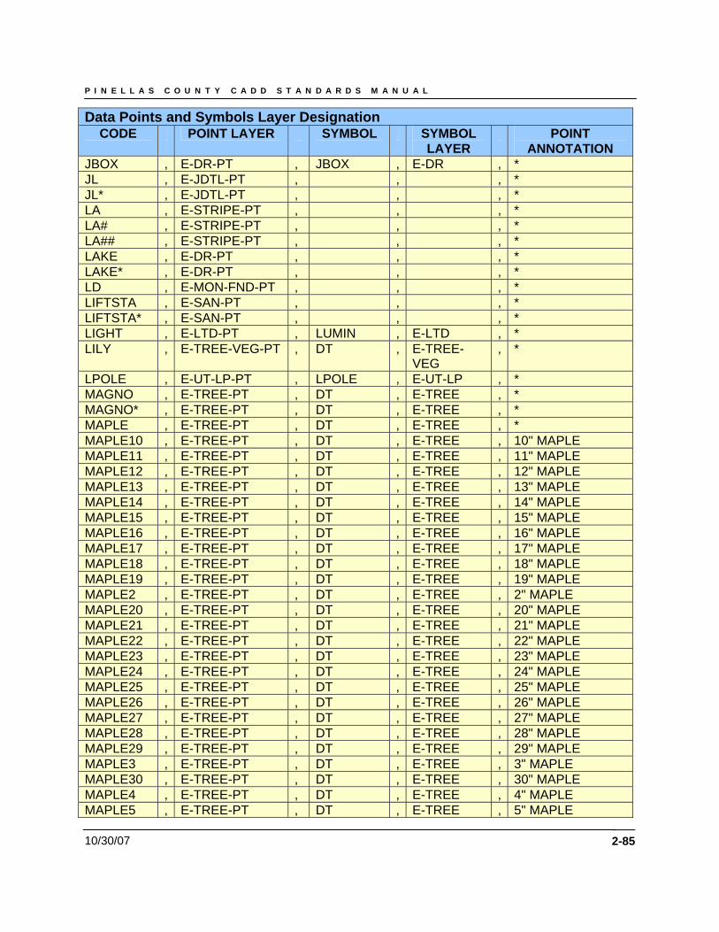
P I N E L L A S C O U N T Y C A D D S T A N D A R D S M A N U A L
10/30/07 2-85
Data Points and Symbols Layer Designation CODE POINT LAYER SYMBOL SYMBOL
LAYER POINT
ANNOTATION JBOX , E-DR-PT , JBOX , E-DR , * JL , E-JDTL-PT , , , * JL* , E-JDTL-PT , , , * LA , E-STRIPE-PT , , , * LA# , E-STRIPE-PT , , , * LA## , E-STRIPE-PT , , , * LAKE , E-DR-PT , , , * LAKE* , E-DR-PT , , , * LD , E-MON-FND-PT , , , * LIFTSTA , E-SAN-PT , , , * LIFTSTA* , E-SAN-PT , , , * LIGHT , E-LTD-PT , LUMIN , E-LTD , * LILY , E-TREE-VEG-PT , DT , E-TREE-
VEG , *
LPOLE , E-UT-LP-PT , LPOLE , E-UT-LP , * MAGNO , E-TREE-PT , DT , E-TREE , * MAGNO* , E-TREE-PT , DT , E-TREE , * MAPLE , E-TREE-PT , DT , E-TREE , * MAPLE10 , E-TREE-PT , DT , E-TREE , 10" MAPLE MAPLE11 , E-TREE-PT , DT , E-TREE , 11" MAPLE MAPLE12 , E-TREE-PT , DT , E-TREE , 12" MAPLE MAPLE13 , E-TREE-PT , DT , E-TREE , 13" MAPLE MAPLE14 , E-TREE-PT , DT , E-TREE , 14" MAPLE MAPLE15 , E-TREE-PT , DT , E-TREE , 15" MAPLE MAPLE16 , E-TREE-PT , DT , E-TREE , 16" MAPLE MAPLE17 , E-TREE-PT , DT , E-TREE , 17" MAPLE MAPLE18 , E-TREE-PT , DT , E-TREE , 18" MAPLE MAPLE19 , E-TREE-PT , DT , E-TREE , 19" MAPLE MAPLE2 , E-TREE-PT , DT , E-TREE , 2" MAPLE MAPLE20 , E-TREE-PT , DT , E-TREE , 20" MAPLE MAPLE21 , E-TREE-PT , DT , E-TREE , 21" MAPLE MAPLE22 , E-TREE-PT , DT , E-TREE , 22" MAPLE MAPLE23 , E-TREE-PT , DT , E-TREE , 23" MAPLE MAPLE24 , E-TREE-PT , DT , E-TREE , 24" MAPLE MAPLE25 , E-TREE-PT , DT , E-TREE , 25" MAPLE MAPLE26 , E-TREE-PT , DT , E-TREE , 26" MAPLE MAPLE27 , E-TREE-PT , DT , E-TREE , 27" MAPLE MAPLE28 , E-TREE-PT , DT , E-TREE , 28" MAPLE MAPLE29 , E-TREE-PT , DT , E-TREE , 29" MAPLE MAPLE3 , E-TREE-PT , DT , E-TREE , 3" MAPLE MAPLE30 , E-TREE-PT , DT , E-TREE , 30" MAPLE MAPLE4 , E-TREE-PT , DT , E-TREE , 4" MAPLE MAPLE5 , E-TREE-PT , DT , E-TREE , 5" MAPLE
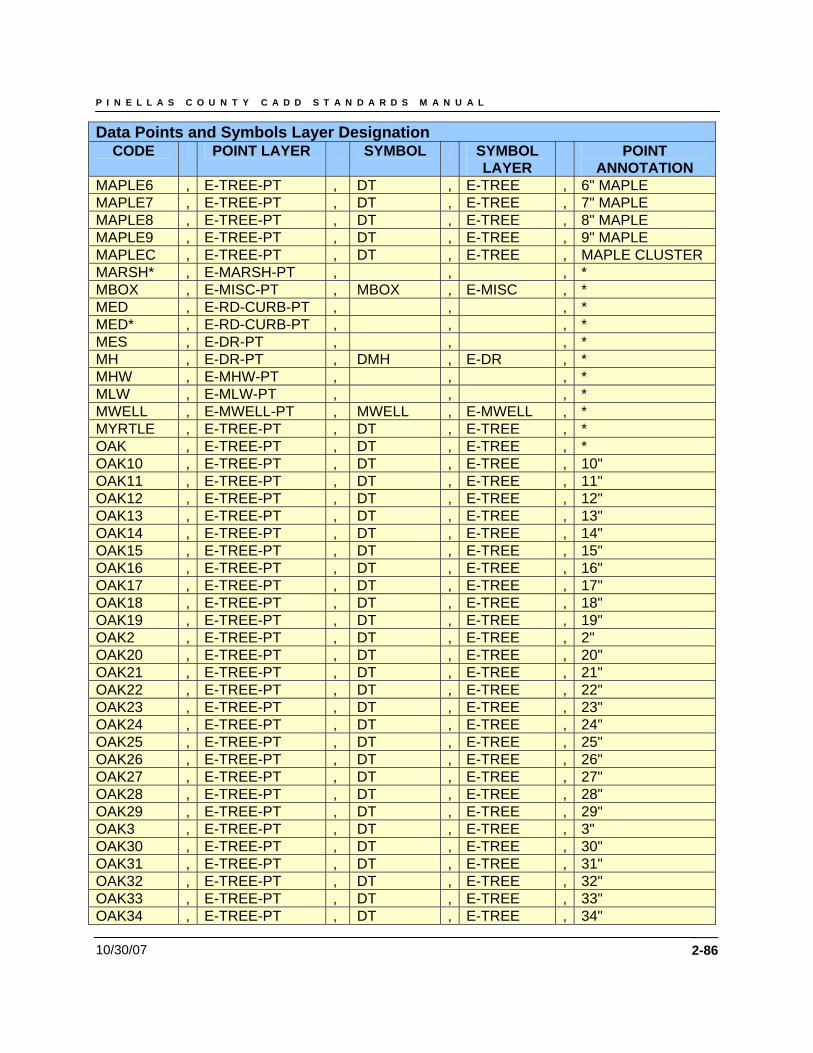
P I N E L L A S C O U N T Y C A D D S T A N D A R D S M A N U A L
10/30/07 2-86
Data Points and Symbols Layer Designation CODE POINT LAYER SYMBOL SYMBOL
LAYER POINT
ANNOTATION MAPLE6 , E-TREE-PT , DT , E-TREE , 6" MAPLE MAPLE7 , E-TREE-PT , DT , E-TREE , 7" MAPLE MAPLE8 , E-TREE-PT , DT , E-TREE , 8" MAPLE MAPLE9 , E-TREE-PT , DT , E-TREE , 9" MAPLE MAPLEC , E-TREE-PT , DT , E-TREE , MAPLE CLUSTER MARSH* , E-MARSH-PT , , , * MBOX , E-MISC-PT , MBOX , E-MISC , * MED , E-RD-CURB-PT , , , * MED* , E-RD-CURB-PT , , , * MES , E-DR-PT , , , * MH , E-DR-PT , DMH , E-DR , * MHW , E-MHW-PT , , , * MLW , E-MLW-PT , , , * MWELL , E-MWELL-PT , MWELL , E-MWELL , * MYRTLE , E-TREE-PT , DT , E-TREE , * OAK , E-TREE-PT , DT , E-TREE , * OAK10 , E-TREE-PT , DT , E-TREE , 10" OAK11 , E-TREE-PT , DT , E-TREE , 11" OAK12 , E-TREE-PT , DT , E-TREE , 12" OAK13 , E-TREE-PT , DT , E-TREE , 13" OAK14 , E-TREE-PT , DT , E-TREE , 14" OAK15 , E-TREE-PT , DT , E-TREE , 15" OAK16 , E-TREE-PT , DT , E-TREE , 16" OAK17 , E-TREE-PT , DT , E-TREE , 17" OAK18 , E-TREE-PT , DT , E-TREE , 18" OAK19 , E-TREE-PT , DT , E-TREE , 19" OAK2 , E-TREE-PT , DT , E-TREE , 2" OAK20 , E-TREE-PT , DT , E-TREE , 20" OAK21 , E-TREE-PT , DT , E-TREE , 21" OAK22 , E-TREE-PT , DT , E-TREE , 22" OAK23 , E-TREE-PT , DT , E-TREE , 23" OAK24 , E-TREE-PT , DT , E-TREE , 24" OAK25 , E-TREE-PT , DT , E-TREE , 25" OAK26 , E-TREE-PT , DT , E-TREE , 26" OAK27 , E-TREE-PT , DT , E-TREE , 27" OAK28 , E-TREE-PT , DT , E-TREE , 28" OAK29 , E-TREE-PT , DT , E-TREE , 29" OAK3 , E-TREE-PT , DT , E-TREE , 3" OAK30 , E-TREE-PT , DT , E-TREE , 30" OAK31 , E-TREE-PT , DT , E-TREE , 31" OAK32 , E-TREE-PT , DT , E-TREE , 32" OAK33 , E-TREE-PT , DT , E-TREE , 33" OAK34 , E-TREE-PT , DT , E-TREE , 34"
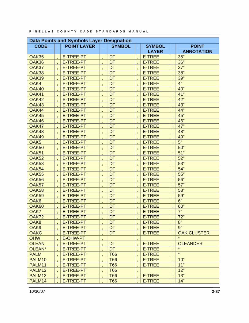
P I N E L L A S C O U N T Y C A D D S T A N D A R D S M A N U A L
10/30/07 2-87
Data Points and Symbols Layer Designation CODE POINT LAYER SYMBOL SYMBOL
LAYER POINT
ANNOTATION OAK35 , E-TREE-PT , DT , E-TREE , 35" OAK36 , E-TREE-PT , DT , E-TREE , 36" OAK37 , E-TREE-PT , DT , E-TREE , 37" OAK38 , E-TREE-PT , DT , E-TREE , 38" OAK39 , E-TREE-PT , DT , E-TREE , 39" OAK4 , E-TREE-PT , DT , E-TREE , 4" OAK40 , E-TREE-PT , DT , E-TREE , 40" OAK41 , E-TREE-PT , DT , E-TREE , 41" OAK42 , E-TREE-PT , DT , E-TREE , 42" OAK43 , E-TREE-PT , DT , E-TREE , 43" OAK44 , E-TREE-PT , DT , E-TREE , 44" OAK45 , E-TREE-PT , DT , E-TREE , 45" OAK46 , E-TREE-PT , DT , E-TREE , 46" OAK47 , E-TREE-PT , DT , E-TREE , 47" OAK48 , E-TREE-PT , DT , E-TREE , 48" OAK49 , E-TREE-PT , DT , E-TREE , 49" OAK5 , E-TREE-PT , DT , E-TREE , 5" OAK50 , E-TREE-PT , DT , E-TREE , 50" OAK51 , E-TREE-PT , DT , E-TREE , 51" OAK52 , E-TREE-PT , DT , E-TREE , 52" OAK53 , E-TREE-PT , DT , E-TREE , 53" OAK54 , E-TREE-PT , DT , E-TREE , 54" OAK55 , E-TREE-PT , DT , E-TREE , 55" OAK56 , E-TREE-PT , DT , E-TREE , 56" OAK57 , E-TREE-PT , DT , E-TREE , 57" OAK58 , E-TREE-PT , DT , E-TREE , 58" OAK59 , E-TREE-PT , DT , E-TREE , 59" OAK6 , E-TREE-PT , DT , E-TREE , 6" OAK60 , E-TREE-PT , DT , E-TREE , 60" OAK7 , E-TREE-PT , DT , E-TREE , 7" OAK72 , E-TREE-PT , DT , E-TREE , 72" OAK8 , E-TREE-PT , DT , E-TREE , 8" OAK9 , E-TREE-PT , DT , E-TREE , 9" OAKC , E-TREE-PT , DT , E-TREE , OAK CLUSTER OHW , E-OHW-PT , , , * OLEAN , E-TREE-PT , DT , E-TREE , OLEANDER OLEAN* , E-TREE-PT , DT , E-TREE , * PALM , E-TREE-PT , T66 , E-TREE , * PALM10 , E-TREE-PT , T66 , E-TREE , 10" PALM11 , E-TREE-PT , T66 , E-TREE , 11" PALM12 , E-TREE-PT , T66 , , 12" PALM13 , E-TREE-PT , T66 , E-TREE , 13" PALM14 , E-TREE-PT , T66 , E-TREE , 14"
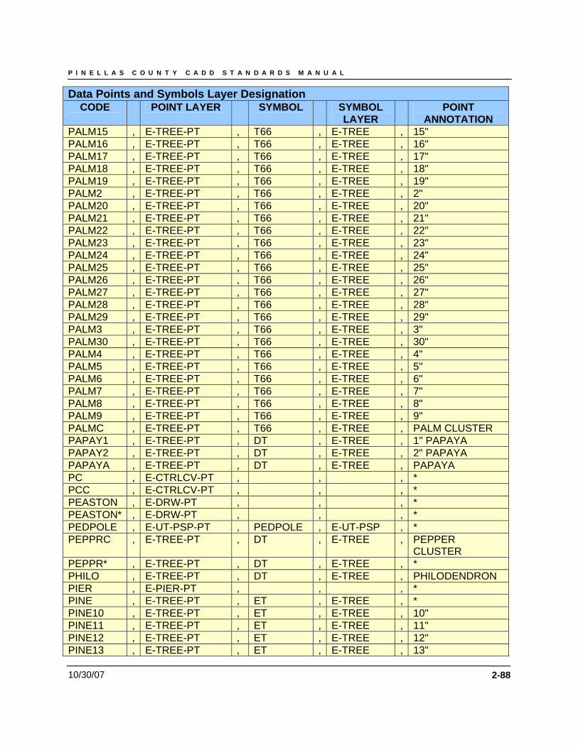
P I N E L L A S C O U N T Y C A D D S T A N D A R D S M A N U A L
10/30/07 2-88
Data Points and Symbols Layer Designation CODE POINT LAYER SYMBOL SYMBOL
LAYER POINT
ANNOTATION PALM15 , E-TREE-PT , T66 , E-TREE , 15" PALM16 , E-TREE-PT , T66 , E-TREE , 16" PALM17 , E-TREE-PT , T66 , E-TREE , 17" PALM18 , E-TREE-PT , T66 , E-TREE , 18" PALM19 , E-TREE-PT , T66 , E-TREE , 19" PALM2 , E-TREE-PT , T66 , E-TREE , 2" PALM20 , E-TREE-PT , T66 , E-TREE , 20" PALM21 , E-TREE-PT , T66 , E-TREE , 21" PALM22 , E-TREE-PT , T66 , E-TREE , 22" PALM23 , E-TREE-PT , T66 , E-TREE , 23" PALM24 , E-TREE-PT , T66 , E-TREE , 24" PALM25 , E-TREE-PT , T66 , E-TREE , 25" PALM26 , E-TREE-PT , T66 , E-TREE , 26" PALM27 , E-TREE-PT , T66 , E-TREE , 27" PALM28 , E-TREE-PT , T66 , E-TREE , 28" PALM29 , E-TREE-PT , T66 , E-TREE , 29" PALM3 , E-TREE-PT , T66 , E-TREE , 3" PALM30 , E-TREE-PT , T66 , E-TREE , 30" PALM4 , E-TREE-PT , T66 , E-TREE , 4" PALM5 , E-TREE-PT , T66 , E-TREE , 5" PALM6 , E-TREE-PT , T66 , E-TREE , 6" PALM7 , E-TREE-PT , T66 , E-TREE , 7" PALM8 , E-TREE-PT , T66 , E-TREE , 8" PALM9 , E-TREE-PT , T66 , E-TREE , 9" PALMC , E-TREE-PT , T66 , E-TREE , PALM CLUSTER PAPAY1 , E-TREE-PT , DT , E-TREE , 1" PAPAYA PAPAY2 , E-TREE-PT , DT , E-TREE , 2" PAPAYA PAPAYA , E-TREE-PT , DT , E-TREE , PAPAYA PC , E-CTRLCV-PT , , , * PCC , E-CTRLCV-PT , , , * PEASTON , E-DRW-PT , , , * PEASTON* , E-DRW-PT , , , * PEDPOLE , E-UT-PSP-PT , PEDPOLE , E-UT-PSP , * PEPPRC , E-TREE-PT , DT , E-TREE , PEPPER
CLUSTER PEPPR* , E-TREE-PT , DT , E-TREE , * PHILO , E-TREE-PT , DT , E-TREE , PHILODENDRON PIER , E-PIER-PT , , , * PINE , E-TREE-PT , ET , E-TREE , * PINE10 , E-TREE-PT , ET , E-TREE , 10" PINE11 , E-TREE-PT , ET , E-TREE , 11" PINE12 , E-TREE-PT , ET , E-TREE , 12" PINE13 , E-TREE-PT , ET , E-TREE , 13"
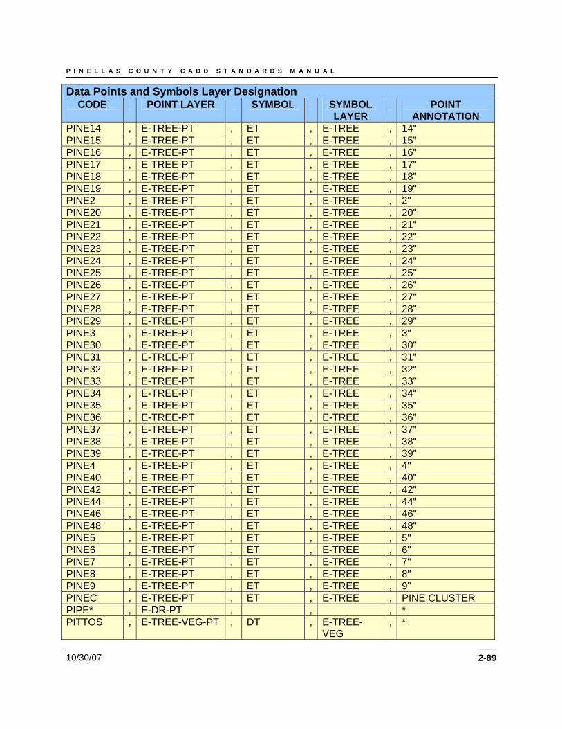
P I N E L L A S C O U N T Y C A D D S T A N D A R D S M A N U A L
10/30/07 2-89
Data Points and Symbols Layer Designation CODE POINT LAYER SYMBOL SYMBOL
LAYER POINT
ANNOTATION PINE14 , E-TREE-PT , ET , E-TREE , 14" PINE15 , E-TREE-PT , ET , E-TREE , 15" PINE16 , E-TREE-PT , ET , E-TREE , 16" PINE17 , E-TREE-PT , ET , E-TREE , 17" PINE18 , E-TREE-PT , ET , E-TREE , 18" PINE19 , E-TREE-PT , ET , E-TREE , 19" PINE2 , E-TREE-PT , ET , E-TREE , 2" PINE20 , E-TREE-PT , ET , E-TREE , 20" PINE21 , E-TREE-PT , ET , E-TREE , 21" PINE22 , E-TREE-PT , ET , E-TREE , 22" PINE23 , E-TREE-PT , ET , E-TREE , 23" PINE24 , E-TREE-PT , ET , E-TREE , 24" PINE25 , E-TREE-PT , ET , E-TREE , 25" PINE26 , E-TREE-PT , ET , E-TREE , 26" PINE27 , E-TREE-PT , ET , E-TREE , 27" PINE28 , E-TREE-PT , ET , E-TREE , 28" PINE29 , E-TREE-PT , ET , E-TREE , 29" PINE3 , E-TREE-PT , ET , E-TREE , 3" PINE30 , E-TREE-PT , ET , E-TREE , 30" PINE31 , E-TREE-PT , ET , E-TREE , 31" PINE32 , E-TREE-PT , ET , E-TREE , 32" PINE33 , E-TREE-PT , ET , E-TREE , 33" PINE34 , E-TREE-PT , ET , E-TREE , 34" PINE35 , E-TREE-PT , ET , E-TREE , 35" PINE36 , E-TREE-PT , ET , E-TREE , 36" PINE37 , E-TREE-PT , ET , E-TREE , 37" PINE38 , E-TREE-PT , ET , E-TREE , 38" PINE39 , E-TREE-PT , ET , E-TREE , 39" PINE4 , E-TREE-PT , ET , E-TREE , 4" PINE40 , E-TREE-PT , ET , E-TREE , 40" PINE42 , E-TREE-PT , ET , E-TREE , 42" PINE44 , E-TREE-PT , ET , E-TREE , 44" PINE46 , E-TREE-PT , ET , E-TREE , 46" PINE48 , E-TREE-PT , ET , E-TREE , 48" PINE5 , E-TREE-PT , ET , E-TREE , 5" PINE6 , E-TREE-PT , ET , E-TREE , 6" PINE7 , E-TREE-PT , ET , E-TREE , 7" PINE8 , E-TREE-PT , ET , E-TREE , 8" PINE9 , E-TREE-PT , ET , E-TREE , 9" PINEC , E-TREE-PT , ET , E-TREE , PINE CLUSTER PIPE* , E-DR-PT , , , * PITTOS , E-TREE-VEG-PT , DT , E-TREE-
VEG , *
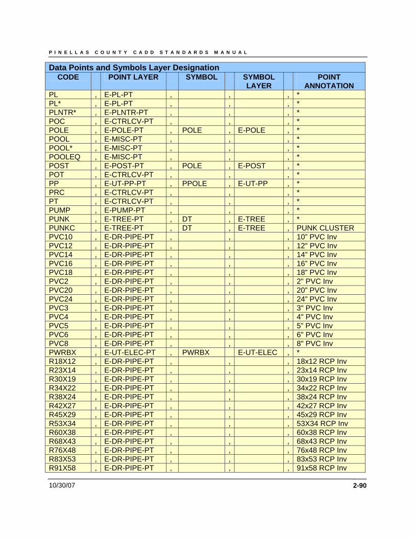
P I N E L L A S C O U N T Y C A D D S T A N D A R D S M A N U A L
10/30/07 2-90
Data Points and Symbols Layer Designation CODE POINT LAYER SYMBOL SYMBOL
LAYER POINT
ANNOTATION PL , E-PL-PT , , , * PL* , E-PL-PT , , , * PLNTR* , E-PLNTR-PT , , , * POC , E-CTRLCV-PT , , , * POLE , E-POLE-PT , POLE , E-POLE , * POOL , E-MISC-PT , , , * POOL* , E-MISC-PT , , , * POOLEQ , E-MISC-PT , , , * POST , E-POST-PT , POLE , E-POST , * POT , E-CTRLCV-PT , , , * PP , E-UT-PP-PT , PPOLE , E-UT-PP , * PRC , E-CTRLCV-PT , , , * PT , E-CTRLCV-PT , , , * PUMP , E-PUMP-PT , , , * PUNK , E-TREE-PT , DT , E-TREE , * PUNKC , E-TREE-PT , DT , E-TREE , PUNK CLUSTER PVC10 , E-DR-PIPE-PT , , , 10” PVC Inv PVC12 , E-DR-PIPE-PT , , , 12" PVC Inv PVC14 , E-DR-PIPE-PT , , , 14” PVC Inv PVC16 , E-DR-PIPE-PT , , , 16” PVC Inv PVC18 , E-DR-PIPE-PT , , , 18” PVC Inv PVC2 , E-DR-PIPE-PT , , , 2" PVC Inv PVC20 , E-DR-PIPE-PT , , , 20” PVC Inv PVC24 , E-DR-PIPE-PT , , , 24” PVC Inv PVC3 , E-DR-PIPE-PT , , , 3" PVC Inv PVC4 , E-DR-PIPE-PT , , , 4" PVC Inv PVC5 , E-DR-PIPE-PT , , , 5” PVC Inv PVC6 , E-DR-PIPE-PT , , , 6" PVC Inv PVC8 , E-DR-PIPE-PT , , , 8" PVC Inv PWRBX , E-UT-ELEC-PT , PWRBX E-UT-ELEC , * R18X12 , E-DR-PIPE-PT , , , 18x12 RCP Inv R23X14 , E-DR-PIPE-PT , , , 23x14 RCP Inv R30X19 , E-DR-PIPE-PT , , , 30x19 RCP Inv R34X22 , E-DR-PIPE-PT , , , 34x22 RCP Inv R38X24 , E-DR-PIPE-PT , , , 38x24 RCP Inv R42X27 , E-DR-PIPE-PT , , , 42x27 RCP Inv R45X29 , E-DR-PIPE-PT , , , 45x29 RCP Inv R53X34 , E-DR-PIPE-PT , , , 53X34 RCP Inv R60X38 , E-DR-PIPE-PT , , , 60x38 RCP Inv R68X43 , E-DR-PIPE-PT , , , 68x43 RCP Inv R76X48 , E-DR-PIPE-PT , , , 76x48 RCP Inv R83X53 , E-DR-PIPE-PT , , , 83x53 RCP Inv R91X58 , E-DR-PIPE-PT , , , 91x58 RCP Inv
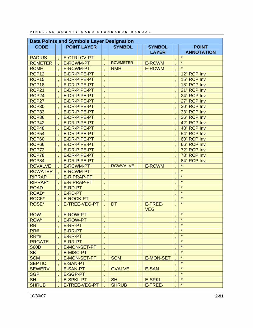
P I N E L L A S C O U N T Y C A D D S T A N D A R D S M A N U A L
10/30/07 2-91
Data Points and Symbols Layer Designation CODE POINT LAYER SYMBOL SYMBOL
LAYER POINT
ANNOTATION RADIUS , E-CTRLCV-PT , , , * RCMETER , E-RCWM-PT , RCWMETER , E-RCWM , * RCMH , E-RCWM-PT , RMH , E-RCWM , * RCP12 , E-DR-PIPE-PT , , , 12" RCP Inv RCP15 , E-DR-PIPE-PT , , , 15" RCP Inv RCP18 , E-DR-PIPE-PT , , , 18" RCP Inv RCP21 , E-DR-PIPE-PT , , , 21" RCP Inv RCP24 , E-DR-PIPE-PT , , , 24" RCP Inv RCP27 , E-DR-PIPE-PT , , , 27" RCP Inv RCP30 , E-DR-PIPE-PT , , , 30" RCP Inv RCP33 , E-DR-PIPE-PT , , , 33" RCP Inv RCP36 , E-DR-PIPE-PT , , , 36" RCP Inv RCP42 , E-DR-PIPE-PT , , , 42" RCP Inv RCP48 , E-DR-PIPE-PT , , , 48" RCP Inv RCP54 , E-DR-PIPE-PT , , , 54" RCP Inv RCP60 , E-DR-PIPE-PT , , , 60” RCP Inv RCP66 , E-DR-PIPE-PT , , , 66” RCP Inv RCP72 , E-DR-PIPE-PT , , , 72” RCP Inv RCP78 , E-DR-PIPE-PT , , , 78” RCP Inv RCP84 , E-DR-PIPE-PT , , , 84” RCP Inv RCVALVE , E-RCWM-PT , RCWVALVE , E-RCWM , * RCWATER , E-RCWM-PT , , , * RIPRAP , E-RIPRAP-PT , , , * RIPRAP* , E-RIPRAP-PT , , , * ROAD , E-RD-PT , , , * ROAD* , E-RD-PT , , , * ROCK* , E-ROCK-PT , , , * ROSE* , E-TREE-VEG-PT , DT , E-TREE-
VEG , *
ROW , E-ROW-PT , , , * ROW* , E-ROW-PT , , , * RR , E-RR-PT , , , * RR# , E-RR-PT , , , * RR## , E-RR-PT , , , * RRGATE , E-RR-PT , , , * S60D , E-MON-SET-PT , , , * SB , E-MISC-PT , , , * SCM , E-MON-SET-PT , SCM , E-MON-SET , * SEPTIC , E-SAN-PT , , , * SEWERV , E-SAN-PT , GVALVE , E-SAN , * SGP , E-SGP-PT , , , * SH , E-SPKL-PT , SH , E-SPKL , * SHRUB , E-TREE-VEG-PT , SHRUB , E-TREE- , *
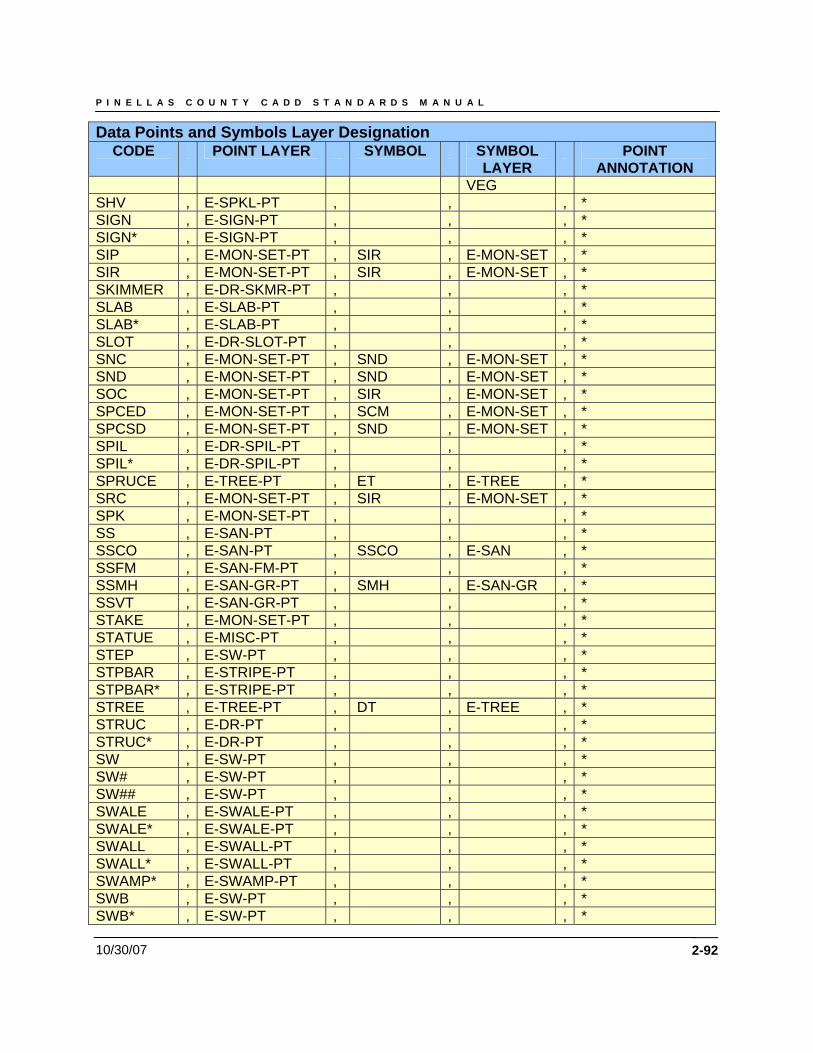
P I N E L L A S C O U N T Y C A D D S T A N D A R D S M A N U A L
10/30/07 2-92
Data Points and Symbols Layer Designation CODE POINT LAYER SYMBOL SYMBOL
LAYER POINT
ANNOTATION VEG
SHV , E-SPKL-PT , , , * SIGN , E-SIGN-PT , , , * SIGN* , E-SIGN-PT , , , * SIP , E-MON-SET-PT , SIR , E-MON-SET , * SIR , E-MON-SET-PT , SIR , E-MON-SET , * SKIMMER , E-DR-SKMR-PT , , , * SLAB , E-SLAB-PT , , , * SLAB* , E-SLAB-PT , , , * SLOT , E-DR-SLOT-PT , , , * SNC , E-MON-SET-PT , SND , E-MON-SET , * SND , E-MON-SET-PT , SND , E-MON-SET , * SOC , E-MON-SET-PT , SIR , E-MON-SET , * SPCED , E-MON-SET-PT , SCM , E-MON-SET , * SPCSD , E-MON-SET-PT , SND , E-MON-SET , * SPIL , E-DR-SPIL-PT , , , * SPIL* , E-DR-SPIL-PT , , , * SPRUCE , E-TREE-PT , ET , E-TREE , * SRC , E-MON-SET-PT , SIR , E-MON-SET , * SPK , E-MON-SET-PT , , , * SS , E-SAN-PT , , , * SSCO , E-SAN-PT , SSCO , E-SAN , * SSFM , E-SAN-FM-PT , , , * SSMH , E-SAN-GR-PT , SMH , E-SAN-GR , * SSVT , E-SAN-GR-PT , , , * STAKE , E-MON-SET-PT , , , * STATUE , E-MISC-PT , , , * STEP , E-SW-PT , , , * STPBAR , E-STRIPE-PT , , , * STPBAR* , E-STRIPE-PT , , , * STREE , E-TREE-PT , DT , E-TREE , * STRUC , E-DR-PT , , , * STRUC* , E-DR-PT , , , * SW , E-SW-PT , , , * SW# , E-SW-PT , , , * SW## , E-SW-PT , , , * SWALE , E-SWALE-PT , , , * SWALE* , E-SWALE-PT , , , * SWALL , E-SWALL-PT , , , * SWALL* , E-SWALL-PT , , , * SWAMP* , E-SWAMP-PT , , , * SWB , E-SW-PT , , , * SWB* , E-SW-PT , , , *
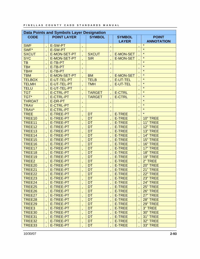
P I N E L L A S C O U N T Y C A D D S T A N D A R D S M A N U A L
10/30/07 2-93
Data Points and Symbols Layer Designation CODE POINT LAYER SYMBOL SYMBOL
LAYER POINT
ANNOTATION SWF , E-SW-PT , , , * SWF* , E-SW-PT , , , * SXCUT , E-MON-SET-PT , SXCUT , E-MON-SET , * SYC , E-MON-SET-PT , SIR , E-MON-SET , * TB , E-TB-PT , , , * TB# , E-TB-PT , , , * TB## , E-TB-PT , , , * TBM , E-MON-SET-PT , BM , E-MON-SET , * TELBOX , E-UT-TEL-PT , TELB , E-UT-TEL , * TELMH , E-UT-TEL-PT , TMH , E-UT-TEL , * TELU , E-UT-TEL-PT , , , * TGT , E-CTRL-PT , TARGET , E-CTRL , * TGT* , E-CTRL-PT , TARGET , E-CTRL , * THROAT , E-DR-PT , , , * TRAV , E-CTRL-PT , , , * TRAV* , E-CTRL-PT , , , * TREE , E-TREE-PT , DT , E-TREE , * TREE10 , E-TREE-PT , DT , E-TREE , 10" TREE TREE11 , E-TREE-PT , DT , E-TREE , 11" TREE TREE12 , E-TREE-PT , DT , E-TREE , 12" TREE TREE13 , E-TREE-PT , DT , E-TREE , 13" TREE TREE14 , E-TREE-PT , DT , E-TREE , 14" TREE TREE15 , E-TREE-PT , DT , E-TREE , 15" TREE TREE16 , E-TREE-PT , DT , E-TREE , 16" TREE TREE17 , E-TREE-PT , DT , E-TREE , 17" TREE TREE18 , E-TREE-PT , DT , E-TREE , 18" TREE TREE19 , E-TREE-PT , DT , E-TREE , 19" TREE TREE2 , E-TREE-PT , DT , E-TREE , 2" TREE TREE20 , E-TREE-PT , DT , E-TREE , 20" TREE TREE21 , E-TREE-PT , DT , E-TREE , 21" TREE TREE22 , E-TREE-PT , DT , E-TREE , 22" TREE TREE23 , E-TREE-PT , DT , E-TREE , 23" TREE TREE24 , E-TREE-PT , DT , E-TREE , 24" TREE TREE25 , E-TREE-PT , DT , E-TREE , 25" TREE TREE26 , E-TREE-PT , DT , E-TREE , 26" TREE TREE27 , E-TREE-PT , DT , E-TREE , 27" TREE TREE28 , E-TREE-PT , DT , E-TREE , 28" TREE TREE29 , E-TREE-PT , DT , E-TREE , 29" TREE TREE3 , E-TREE-PT , DT , E-TREE , 3" TREE TREE30 , E-TREE-PT , DT , E-TREE , 30" TREE TREE31 , E-TREE-PT , DT , E-TREE , 31" TREE TREE32 , E-TREE-PT , DT , E-TREE , 32" TREE TREE33 , E-TREE-PT , DT , E-TREE , 33" TREE
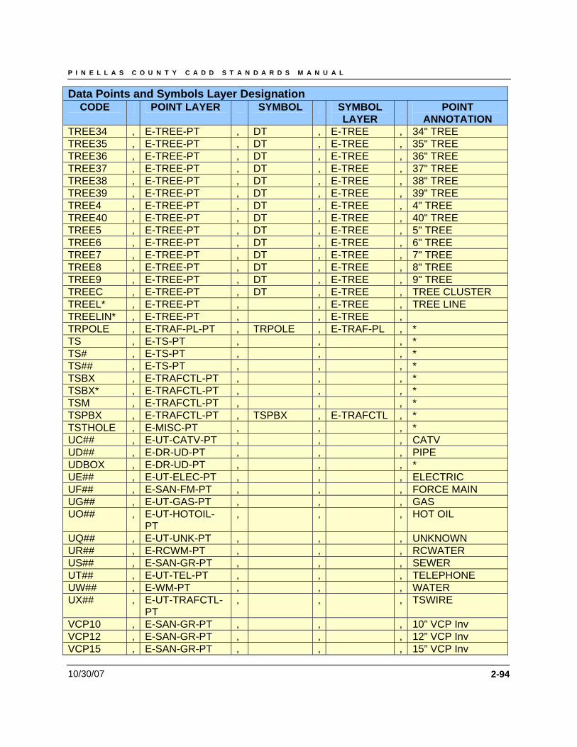
P I N E L L A S C O U N T Y C A D D S T A N D A R D S M A N U A L
10/30/07 2-94
Data Points and Symbols Layer Designation CODE POINT LAYER SYMBOL SYMBOL
LAYER POINT
ANNOTATION TREE34 , E-TREE-PT , DT , E-TREE , 34" TREE TREE35 , E-TREE-PT , DT , E-TREE , 35" TREE TREE36 , E-TREE-PT , DT , E-TREE , 36" TREE TREE37 , E-TREE-PT , DT , E-TREE , 37" TREE TREE38 , E-TREE-PT , DT , E-TREE , 38" TREE TREE39 , E-TREE-PT , DT , E-TREE , 39" TREE TREE4 , E-TREE-PT , DT , E-TREE , 4" TREE TREE40 , E-TREE-PT , DT , E-TREE , 40" TREE TREE5 , E-TREE-PT , DT , E-TREE , 5" TREE TREE6 , E-TREE-PT , DT , E-TREE , 6" TREE TREE7 , E-TREE-PT , DT , E-TREE , 7" TREE TREE8 , E-TREE-PT , DT , E-TREE , 8" TREE TREE9 , E-TREE-PT , DT , E-TREE , 9" TREE TREEC , E-TREE-PT , DT , E-TREE , TREE CLUSTER TREEL* , E-TREE-PT , , E-TREE , TREE LINE TREELIN* , E-TREE-PT , , E-TREE , TRPOLE , E-TRAF-PL-PT , TRPOLE , E-TRAF-PL , * TS , E-TS-PT , , , * TS# , E-TS-PT , , , * TS## , E-TS-PT , , , * TSBX , E-TRAFCTL-PT , , , * TSBX* , E-TRAFCTL-PT , , , * TSM , E-TRAFCTL-PT , , , * TSPBX , E-TRAFCTL-PT , TSPBX , E-TRAFCTL , * TSTHOLE , E-MISC-PT , , , * UC## , E-UT-CATV-PT , , , CATV UD## , E-DR-UD-PT , , , PIPE UDBOX , E-DR-UD-PT , , , * UE## , E-UT-ELEC-PT , , , ELECTRIC UF## , E-SAN-FM-PT , , , FORCE MAIN UG## , E-UT-GAS-PT , , , GAS UO## , E-UT-HOTOIL-
PT , , , HOT OIL
UQ## , E-UT-UNK-PT , , , UNKNOWN UR## , E-RCWM-PT , , , RCWATER US## , E-SAN-GR-PT , , , SEWER UT## , E-UT-TEL-PT , , , TELEPHONE UW## , E-WM-PT , , , WATER UX## , E-UT-TRAFCTL-
PT , , , TSWIRE
VCP10 , E-SAN-GR-PT , , , 10” VCP Inv VCP12 , E-SAN-GR-PT , , , 12” VCP Inv VCP15 , E-SAN-GR-PT , , , 15” VCP Inv
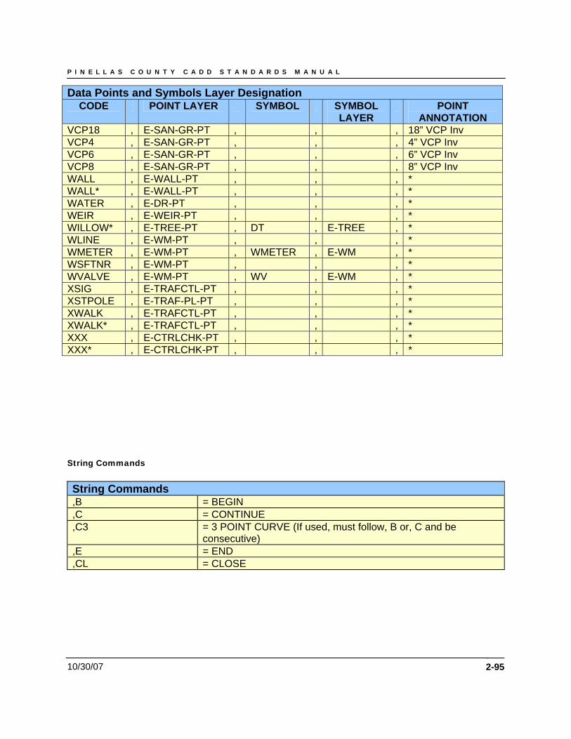
P I N E L L A S C O U N T Y C A D D S T A N D A R D S M A N U A L
10/30/07 2-95
Data Points and Symbols Layer Designation CODE POINT LAYER SYMBOL SYMBOL
LAYER POINT
ANNOTATION VCP18 , E-SAN-GR-PT , , , 18” VCP Inv VCP4 , E-SAN-GR-PT , , , 4” VCP Inv VCP6 , E-SAN-GR-PT , , , 6” VCP Inv VCP8 , E-SAN-GR-PT , , , 8” VCP Inv WALL , E-WALL-PT , , , * WALL* , E-WALL-PT , , , * WATER , E-DR-PT , , , * WEIR , E-WEIR-PT , , , * WILLOW* , E-TREE-PT , DT , E-TREE , * WLINE , E-WM-PT , , , * WMETER , E-WM-PT , WMETER , E-WM , * WSFTNR , E-WM-PT , , , * WVALVE , E-WM-PT , WV , E-WM , * XSIG , E-TRAFCTL-PT , , , * XSTPOLE , E-TRAF-PL-PT , , , * XWALK , E-TRAFCTL-PT , , , * XWALK* , E-TRAFCTL-PT , , , * XXX , E-CTRLCHK-PT , , , * XXX* , E-CTRLCHK-PT , , , * String Commands String Commands ,B = BEGIN ,C = CONTINUE ,C3 = 3 POINT CURVE (If used, must follow, B or, C and be
consecutive) ,E = END ,CL = CLOSE
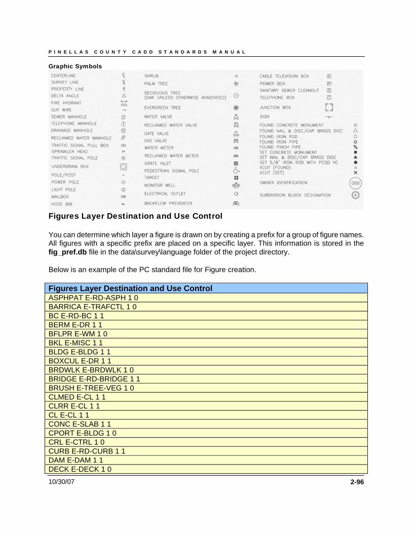
P I N E L L A S C O U N T Y C A D D S T A N D A R D S M A N U A L
10/30/07
Graphic Symbols
Figures Layer Destination and Use Control You can determine which layer a figure is drawn on by creating a prefix for a group of figure names. All figures with a specific prefix are placed on a specific layer. This information is stored in the fig_pref.db file in the data\survey\language folder of the project directory. Below is an example of the PC standard file for Figure creation. Figures Layer Destination and Use Control ASPHPAT E-RD-ASPH 1 0 BARRICA E-TRAFCTL 1 0 BC E-RD-BC 1 1 BERM E-DR 1 1 BFLPR E-WM 1 0 BKL E-MISC 1 1 BLDG E-BLDG 1 1 BOXCUL E-DR 1 1 BRDWLK E-BRDWLK 1 0 BRIDGE E-RD-BRIDGE 1 1 BRUSH E-TREE-VEG 1 0 CLMED E-CL 1 1 CLRR E-CL 1 1 CL E-CL 1 1 CONC E-SLAB 1 1 CPORT E-BLDG 1 0 CRL E-CTRL 1 0 CURB E-RD-CURB 1 1 DAM E-DAM 1 1 DECK E-DECK 1 0
2-96
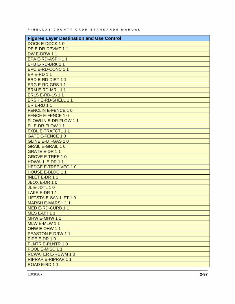
P I N E L L A S C O U N T Y C A D D S T A N D A R D S M A N U A L
10/30/07 2-97
Figures Layer Destination and Use Control DOCK E-DOCK 1 0 DP E-DR-DPVMT 1 1 DW E-DRW 1 1 EPA E-RD-ASPH 1 1 EPB E-RD-BRK 1 1 EPC E-RD-CONC 1 1 EP E-RD 1 1 ERD E-RD-DIRT 1 1 ERG E-RD-GRS 1 1 ERM E-RD-MRL 1 1 ERLS E-RD-LS 1 1 ERSH E-RD-SHELL 1 1 ER E-RD 1 1 FENCLIN E-FENCE 1 0 FENCE E-FENCE 1 0 FLOWLIN E-DR-FLOW 1 1 FL E-DR-FLOW 1 1 FXDL E-TRAFCTL 1 1 GATE E-FENCE 1 0 GLINE E-UT-GAS 1 0 GRAIL E-GRAIL 1 0 GRATE E-DR 1 1 GROVE E-TREE 1 0 HDWALL E-DR 1 1 HEDGE E-TREE VEG 1 0 HOUSE E-BLDG 1 1 INLET E-DR 1 1 JBOX E-DR 1 0 JL E-JDTL 1 0 LAKE E-DR 1 1 LIFTSTA E-SAN-LIFT 1 0 MARSH E-MARSH 1 1 MED E-RD-CURB 1 1 MES E-DR 1 1 MHW E-MHW 1 1 MLW E-MLW 1 1 OHW E-OHW 1 1 PEASTON E-DRW 1 1 PIPE E-DR 1 0 PLNTR E-PLNTR 1 0 POOL E-MISC 1 1 RCWATER E-RCWM 1 0 RIPRAP E-RIPRAP 1 1 ROAD E-RD 1 1
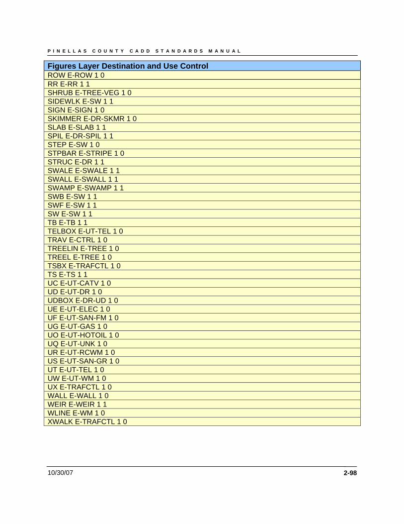
P I N E L L A S C O U N T Y C A D D S T A N D A R D S M A N U A L
10/30/07 2-98
Figures Layer Destination and Use Control ROW E-ROW 1 0 RR E-RR 1 1 SHRUB E-TREE-VEG 1 0 SIDEWLK E-SW 1 1 SIGN E-SIGN 1 0 SKIMMER E-DR-SKMR 1 0 SLAB E-SLAB 1 1 SPIL E-DR-SPIL 1 1 STEP E-SW 1 0 STPBAR E-STRIPE 1 0 STRUC E-DR 1 1 SWALE E-SWALE 1 1 SWALL E-SWALL 1 1 SWAMP E-SWAMP 1 1 SWB E-SW 1 1 SWF E-SW 1 1 SW E-SW 1 1 TB E-TB 1 1 TELBOX E-UT-TEL 1 0 TRAV E-CTRL 1 0 TREELIN E-TREE 1 0 TREEL E-TREE 1 0 TSBX E-TRAFCTL 1 0 TS E-TS 1 1 UC E-UT-CATV 1 0 UD E-UT-DR 1 0 UDBOX E-DR-UD 1 0 UE E-UT-ELEC 1 0 UF E-UT-SAN-FM 1 0 UG E-UT-GAS 1 0 UO E-UT-HOTOIL 1 0 UQ E-UT-UNK 1 0 UR E-UT-RCWM 1 0 US E-UT-SAN-GR 1 0 UT E-UT-TEL 1 0 UW E-UT-WM 1 0 UX E-TRAFCTL 1 0 WALL E-WALL 1 0 WEIR E-WEIR 1 1 WLINE E-WM 1 0 XWALK E-TRAFCTL 1 0
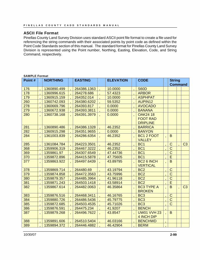
P I N E L L A S C O U N T Y C A D D S T A N D A R D S M A N U A L
10/30/07 2-99
ASCII File Format Pinellas County Land Survey Division uses standard ASCII point file format to create a file used for referencing the string commands with their associated points by point code as defined within the Point Code Standards section of this manual. The standard format for Pinellas County Land Survey Division is represented using the Point number, Northing, Easting, Elevation, Code, and String Command, respectively. SAMPLE Format Point # NORTHING EASTING ELEVATION CODE String
Command176 , 1360890.499 , 264386.1363 , 10.0000 , S60D 178 , 1360996.615 , 264278.686 , 57.4323 , ARBOR 179 , 1360915.159 , 264352.014 , 10.0000 , ASPHPAT 260 , 1360742.093 , 264380.6202 , 59.5352 , AUPIN12 278 , 1360669.796 , 264393.817 , 0.0000 , AVOCADO 279 , 1360672.938 , 264393.3811 , 0.0000 , BANANA 280 , 1360738.168 , 264391.3979 , 0.0000 , OAK24 18
FOOT RAD DRIPLINE
281 , 1360890.486 , 264386.1328 , 46.2352 , BARRICA 282 , 1360915.298 , 264351.9655 , 0.0000 , BANYON 284 , 1361003.839 , 264286.6354 , 46.2352 , BC1 2 FOOT
VALLEY , B
285 , 1361084.784 , 264223.3501 , 46.2352 , BC1 , C , C3368 , 1359906.319 , 264467.3222 , 46.2352 , BC1 , C 369 , 1359861.97 , 264307.6549 , 47.44736 , BC1 , C 370 , 1359872.896 , 264415.5878 , 47.75605 , BC1 , E 377 , 1359863.922 , 264497.6439 , 43.89795 , BC2 6 INCH
VERTICAL , B
378 , 1359869.714 , 264480.69 , 43.19794 , BC2 , C 379 , 1359874.858 , 264472.3563 , 43.75996 , BC2 , C 380 , 1359879.357 , 264485.3964 , 41.96118 , BC2 , C 381 , 1359871.243 , 264503.1418 , 43.58914 , BC2 , E 382 , 1359867.614 , 264482.0063 , 46.35864 , BC3 TYPE A
BROKEN , B , C3
383 , 1359876.516 , 264468.3411 , 46.16765 , BC3 , C 384 , 1359880.726 , 264486.5436 , 45.79775 , BC3 , C 385 , 1359872.685 , 264503.4535 , 45.71026 , BC3 , C 386 , 1359876.591 , 264475.234 , 41.9207 , BENCH , 387 , 1359879.268 , 264496.7622 , 43.8547 , UW01 VVH 23
4 INCH DIP , B
388 , 1359891.606 , 264510.5404 , 46.03166 , BENCHWD , 389 , 1359894.372 , 264446.4882 , 46.42904 , BERM ,
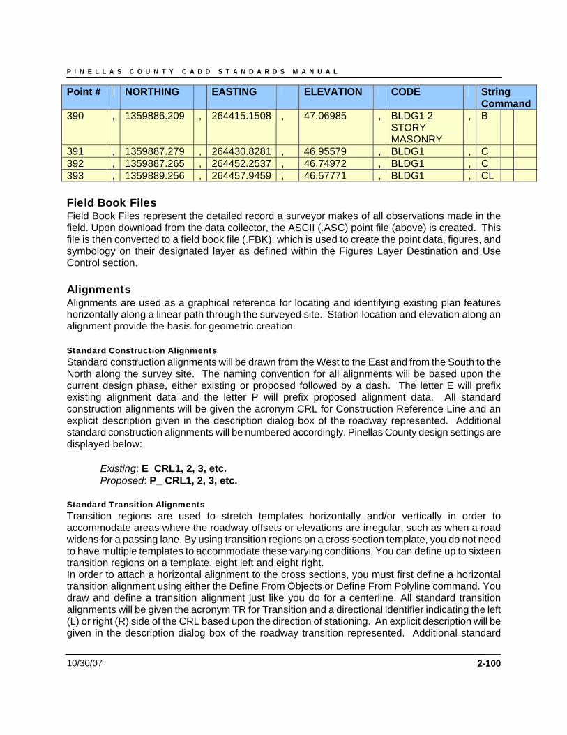
P I N E L L A S C O U N T Y C A D D S T A N D A R D S M A N U A L
10/30/07 2-100
Point # NORTHING EASTING ELEVATION CODE String Command
390 , 1359886.209 , 264415.1508 , 47.06985 , BLDG1 2 STORY MASONRY
, B
391 , 1359887.279 , 264430.8281 , 46.95579 , BLDG1 , C 392 , 1359887.265 , 264452.2537 , 46.74972 , BLDG1 , C 393 , 1359889.256 , 264457.9459 , 46.57771 , BLDG1 , CL Field Book Files Field Book Files represent the detailed record a surveyor makes of all observations made in the field. Upon download from the data collector, the ASCII (.ASC) point file (above) is created. This file is then converted to a field book file (.FBK), which is used to create the point data, figures, and symbology on their designated layer as defined within the Figures Layer Destination and Use Control section. Alignments Alignments are used as a graphical reference for locating and identifying existing plan features horizontally along a linear path through the surveyed site. Station location and elevation along an alignment provide the basis for geometric creation. Standard Construction Alignments Standard construction alignments will be drawn from the West to the East and from the South to the North along the survey site. The naming convention for all alignments will be based upon the current design phase, either existing or proposed followed by a dash. The letter E will prefix existing alignment data and the letter P will prefix proposed alignment data. All standard construction alignments will be given the acronym CRL for Construction Reference Line and an explicit description given in the description dialog box of the roadway represented. Additional standard construction alignments will be numbered accordingly. Pinellas County design settings are displayed below:
Existing: E_CRL1, 2, 3, etc. Proposed: P_ CRL1, 2, 3, etc.
Standard Transition Alignments Transition regions are used to stretch templates horizontally and/or vertically in order to accommodate areas where the roadway offsets or elevations are irregular, such as when a road widens for a passing lane. By using transition regions on a cross section template, you do not need to have multiple templates to accommodate these varying conditions. You can define up to sixteen transition regions on a template, eight left and eight right. In order to attach a horizontal alignment to the cross sections, you must first define a horizontal transition alignment using either the Define From Objects or Define From Polyline command. You draw and define a transition alignment just like you do for a centerline. All standard transition alignments will be given the acronym TR for Transition and a directional identifier indicating the left (L) or right (R) side of the CRL based upon the direction of stationing. An explicit description will be given in the description dialog box of the roadway transition represented. Additional standard

P I N E L L A S C O U N T Y C A D D S T A N D A R D S M A N U A L
10/30/07
transition alignments will be numbered accordingly. Pinellas County design settings are displayed below:
Existing: E_CRL1, 2, 3, etc._TRR_1, 2, 3, etc. – Right Transition Description – Median at left-turn lane Proposed: P_CRL1, 2, 3, etc._TRR_1, 2, 3, etc. – Right Transition Description – Median at left-turn lane
Standard Roadway Alignments – Station Format, Station Labels To control how stations appear in AutoCAD Land Desktop, use the Station Display Format command. This command controls how stations appear for many AutoCAD Land Desktop and Civil Design commands, and it also affects how station labels are created. The Station Display Format command controls the numeric format for the appearance of station labels, as well as precision, decimal character, and the station “+” character.
2-101
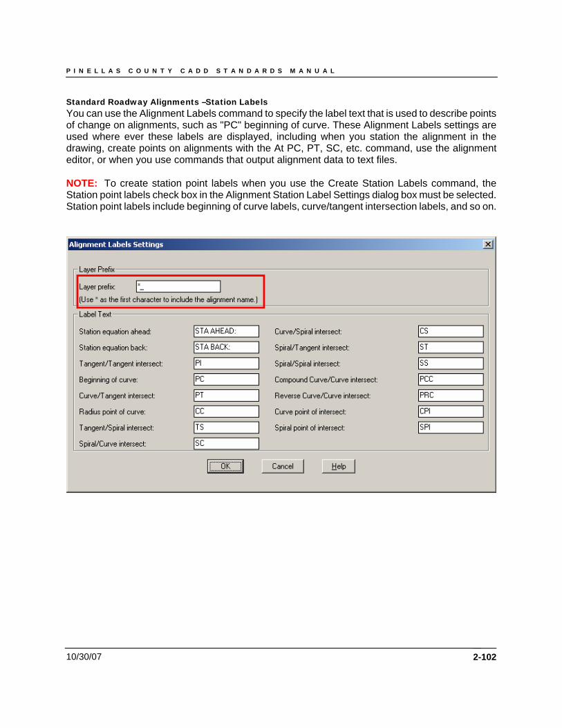
P I N E L L A S C O U N T Y C A D D S T A N D A R D S M A N U A L
10/30/07
Standard Roadway Alignments –Station Labels You can use the Alignment Labels command to specify the label text that is used to describe points of change on alignments, such as "PC" beginning of curve. These Alignment Labels settings are used where ever these labels are displayed, including when you station the alignment in the drawing, create points on alignments with the At PC, PT, SC, etc. command, use the alignment editor, or when you use commands that output alignment data to text files. NOTE: To create station point labels when you use the Create Station Labels command, the Station point labels check box in the Alignment Station Label Settings dialog box must be selected. Station point labels include beginning of curve labels, curve/tangent intersection labels, and so on.
2-102
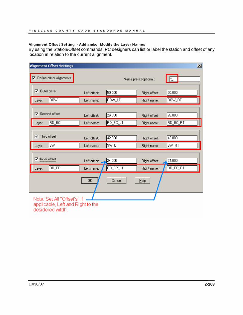
P I N E L L A S C O U N T Y C A D D S T A N D A R D S M A N U A L
10/30/07
Alignment Offset Setting - Add and/or Modify the Layer Names By using the Station/Offset commands, PC designers can list or label the station and offset of any location in relation to the current alignment.
2-103
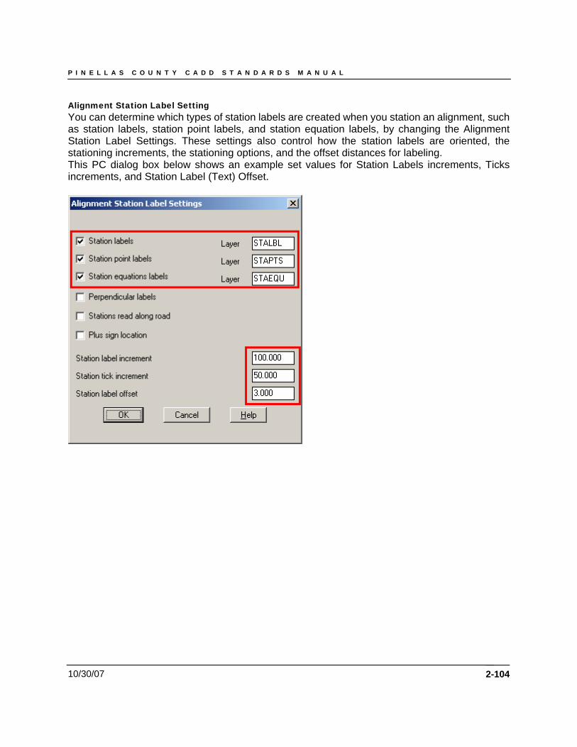
P I N E L L A S C O U N T Y C A D D S T A N D A R D S M A N U A L
10/30/07
Alignment Station Label Setting You can determine which types of station labels are created when you station an alignment, such as station labels, station point labels, and station equation labels, by changing the Alignment Station Label Settings. These settings also control how the station labels are oriented, the stationing increments, the stationing options, and the offset distances for labeling. This PC dialog box below shows an example set values for Station Labels increments, Ticks increments, and Station Label (Text) Offset.
2-104
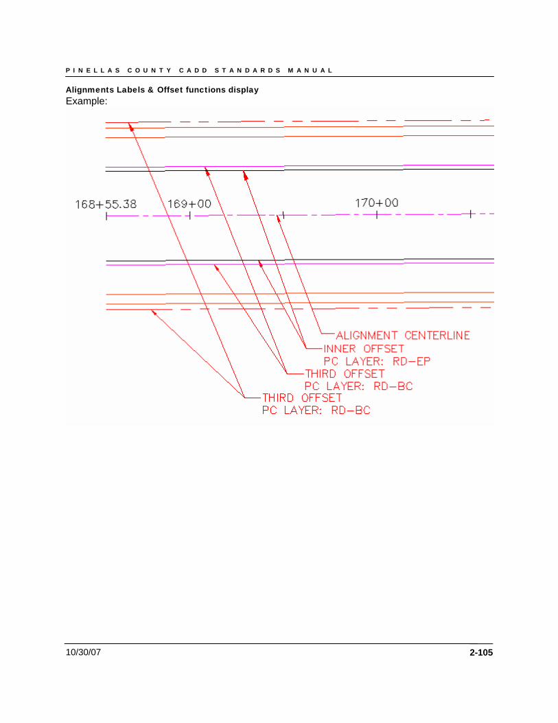
P I N E L L A S C O U N T Y C A D D S T A N D A R D S M A N U A L
10/30/07
Alignments Labels & Offset functions display Example:
2-105
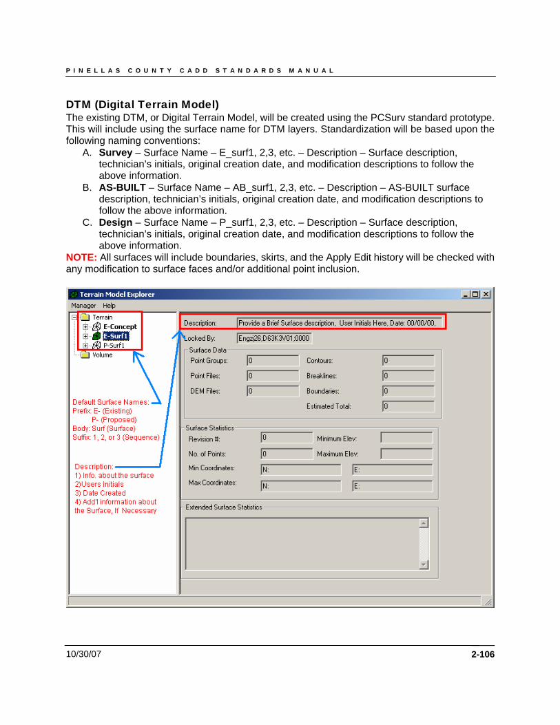
P I N E L L A S C O U N T Y C A D D S T A N D A R D S M A N U A L
10/30/07
DTM (Digital Terrain Model) The existing DTM, or Digital Terrain Model, will be created using the PCSurv standard prototype. This will include using the surface name for DTM layers. Standardization will be based upon the following naming conventions:
A. Survey – Surface Name – E_surf1, 2,3, etc. – Description – Surface description, technician’s initials, original creation date, and modification descriptions to follow the above information.
B. AS-BUILT – Surface Name – AB_surf1, 2,3, etc. – Description – AS-BUILT surface description, technician’s initials, original creation date, and modification descriptions to follow the above information.
C. Design – Surface Name – P_surf1, 2,3, etc. – Description – Surface description, technician’s initials, original creation date, and modification descriptions to follow the above information.
NOTE: All surfaces will include boundaries, skirts, and the Apply Edit history will be checked with any modification to surface faces and/or additional point inclusion.
2-106
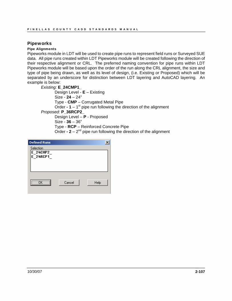
P I N E L L A S C O U N T Y C A D D S T A N D A R D S M A N U A L
10/30/07
Pipeworks Pipe Alignments Pipeworks module in LDT will be used to create pipe runs to represent field runs or Surveyed SUE data. All pipe runs created within LDT Pipeworks module will be created following the direction of their respective alignment or CRL. The preferred naming convention for pipe runs within LDT Pipeworks module will be based upon the order of the run along the CRL alignment, the size and type of pipe being drawn, as well as its level of design, (i.e. Existing or Proposed) which will be separated by an underscore for distinction between LDT layering and AutoCAD layering. An example is below:
Existing: E_24CMP1_ Design Level - E – Existing Size - 24 – 24” Type - CMP – Corrugated Metal Pipe Order - 1 – 1st pipe run following the direction of the alignment
Proposed: P_36RCP2_ Design Level – P - Proposed Size - 36 – 36” Type - RCP – Reinforced Concrete Pipe Order - 2 – 2nd pipe run following the direction of the alignment
2-107
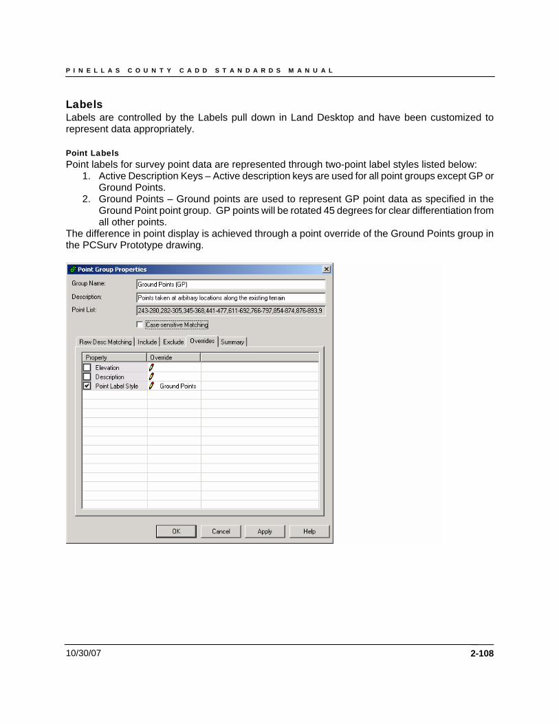
P I N E L L A S C O U N T Y C A D D S T A N D A R D S M A N U A L
10/30/07
Labels Labels are controlled by the Labels pull down in Land Desktop and have been customized to represent data appropriately. Point Labels Point labels for survey point data are represented through two-point label styles listed below:
1. Active Description Keys – Active description keys are used for all point groups except GP or Ground Points.
2. Ground Points – Ground points are used to represent GP point data as specified in the Ground Point point group. GP points will be rotated 45 degrees for clear differentiation from all other points.
The difference in point display is achieved through a point override of the Ground Points group in the PCSurv Prototype drawing.
2-108
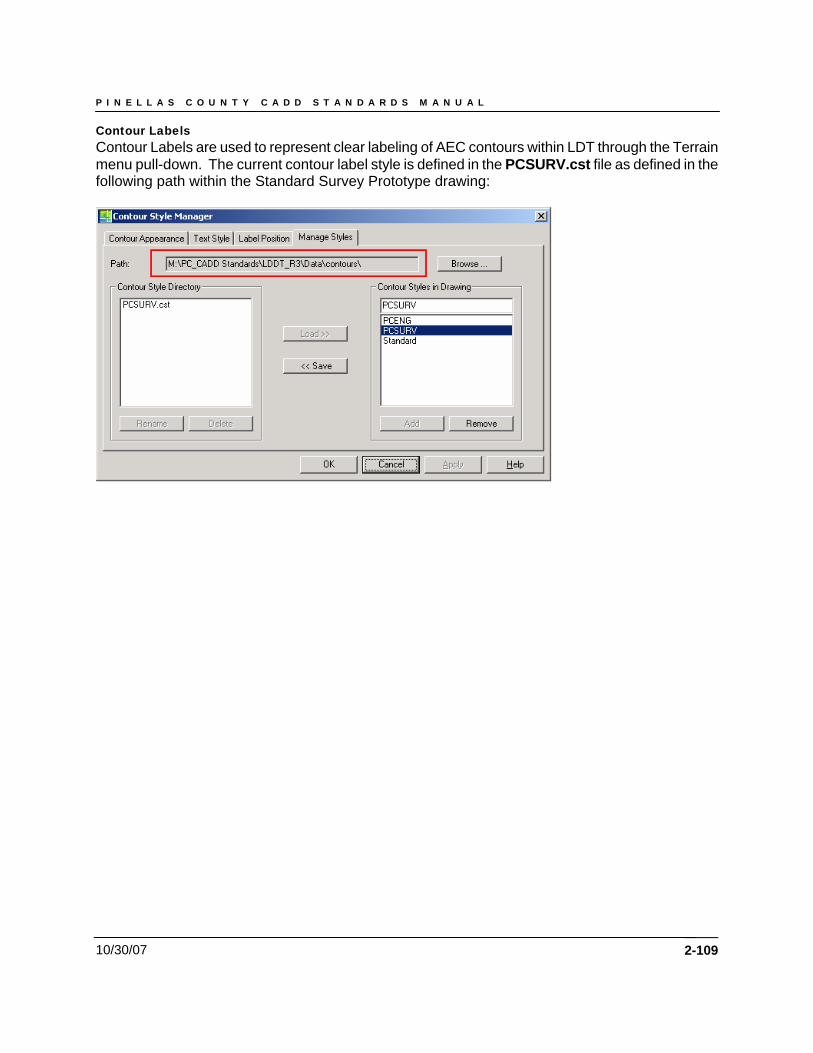
P I N E L L A S C O U N T Y C A D D S T A N D A R D S M A N U A L
10/30/07
Contour Labels Contour Labels are used to represent clear labeling of AEC contours within LDT through the Terrain menu pull-down. The current contour label style is defined in the PCSURV.cst file as defined in the following path within the Standard Survey Prototype drawing:
2-109

P I N E L L A S C O U N T Y C A D D S T A N D A R D S M A N U A L
10/30/07 2-110
P I N E L L A S C O U N T Y C A D D S T A N D A R D S M A N U A L
10/30/07 2-111
Chapter 5
Land Desktop Standards
P I N E L L A S C O U N T Y C A D D S T A N D A R D S M A N U A L
10/30/07 2-112
•

P I N E L L A S C O U N T Y C A D D S T A N D A R D S M A N U A L
10/30/07 2-113
Chapter 6
Project Directory Structure and File Names
P I N E L L A S C O U N T Y C A D D S T A N D A R D S M A N U A L
10/30/07 2-114
P I N E L L A S C O U N T Y C A D D S T A N D A R D S M A N U A L
10/30/07 2-115
Chapter 7
Civil Engineering (LDT)
P I N E L L A S C O U N T Y C A D D S T A N D A R D S M A N U A L
10/30/07 2-116
Chapter 5 - Civil Engineering (LDT)
Points Project data points consist of existing engineering data gathered from the project location as determined by the project’s PM to assist in the engineering development process. Project data points contain both horizontal and vertical data relative to the chosen coordinate zone – NAD 83/90, NGVD 88. Points by Range The point range for Pinellas County - Public Works and Utility Divisions is specified below:
• Project Point data – data representative of the project limits as defined by the project’s PM. All Pinellas County “Proposed” project point data shall occupy the point range of 100,000 to Infinity.
NOTE: If additional project data points are required prior to survey acquisition, it will be necessary for the PM to specify a NAP, or Next Available Point number.
Point Format Project data will be represented and contained within a comma-delimited file stored with the project. The desired data point format for the PC standards is as follows: FIELD ONE --- Point Identifier Number FIELD TWO --- North Coordinate Value FIELD THREE --- East Coordinate Value FIELD FOUR --- Point Elevation FIELD FIVE --- Point Code Identifier FIELD SIX --- Clarification Note Point Groups Project data points will be organized into groups within LDT to facilitate more efficient point data management and utilization. The standard “Proposed” point groups used by all Civil Engineering Division are listed below:
• P-ALL – All survey points in the acquired data point set • P-Hard Shots – survey data points which represent pavement or man-made features • P-Roadway – All information relating to roadway features – (EP, BC, CL, ETC.) • P-Monuments/Control – known field point data used to establish the survey’s base • P-Ground Points – GP or Soft Shots – points taken at arbitrary locations along the existing
terrain • P-Breaklines – a linear or polygonal interruption in the current surface elevation that is used
to distinguish objects of a dissimilar nature, i.e., walls, building pads, structures, etc. • P-Trees – those found on the site of the requested survey
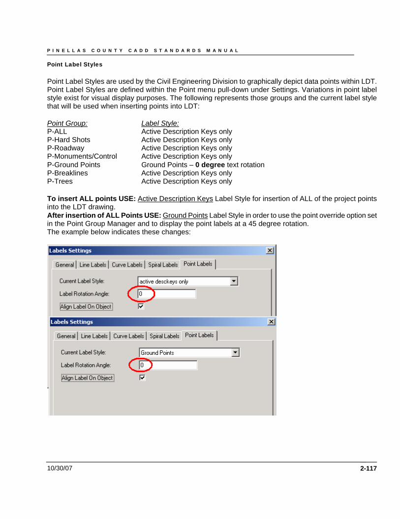
P I N E L L A S C O U N T Y C A D D S T A N D A R D S M A N U A L
10/30/07
Point Label Styles Point Label Styles are used by the Civil Engineering Division to graphically depict data points within LDT. Point Label Styles are defined within the Point menu pull-down under Settings. Variations in point label style exist for visual display purposes. The following represents those groups and the current label style that will be used when inserting points into LDT: Point Group: Label Style: P-ALL Active Description Keys only P-Hard Shots Active Description Keys only P-Roadway Active Description Keys only P-Monuments/Control Active Description Keys only P-Ground Points Ground Points – 0 degree text rotation P-Breaklines Active Description Keys only P-Trees Active Description Keys only To insert ALL points USE: Active Description Keys Label Style for insertion of ALL of the project points into the LDT drawing. After insertion of ALL Points USE: Ground Points Label Style in order to use the point override option set in the Point Group Manager and to display the point labels at a 45 degree rotation. The example below indicates these changes:
2-117

P I N E L L A S C O U N T Y C A D D S T A N D A R D S M A N U A L
10/30/07 2-118
Alignments Alignments are used as a graphical reference for locating and identifying existing plan features horizontally along a linear path through the surveyed site. Station location and elevation along an alignment provide the basis for geometric creation. Standard Construction Alignments Standard construction alignments will be drawn from the West to the East and from the South to the North along the survey site. The naming convention for all alignments will be based upon the current design phase, either existing or proposed followed by a dash. The letter E will prefix existing alignment data and the letter P will prefix proposed alignment data. All standard construction alignments will be given the acronym CRL for Construction Reference Line and an explicit description given in the description dialog box of the roadway represented. Additional standard construction alignments will be numbered accordingly. Pinellas County design settings are displayed below:
Existing: E_CRL1, 2, 3, etc. Description: Georgia Avenue centerline along CR-1 Proposed: P_CRL1, 2, 3, etc. Description: Georgia Avenue centerline along CR-1
Standard Transition Alignments Transition regions are used to stretch templates horizontally and/or vertically in order to accommodate areas where the roadway offsets or elevations are irregular, such as when a road widens for a passing lane. By using transition regions on a cross section template, you do not need to have multiple templates to accommodate these varying conditions. You can define up to sixteen transition regions on a template, eight left and eight right. In order to attach a horizontal alignment to the cross sections, you must first define a horizontal transition alignment using either the Define From Objects or Define From Polyline command. You draw and define a transition alignment just like you do for a centerline. All standard transition alignments will be given the acronym TR for Transition and a directional identifier indicating the left (L) or right (R) side of the CRL based upon the direction of stationing. An explicit description will be given in the description dialog box of the roadway transition represented. Additional standard transition alignments will be numbered accordingly. Pinellas County design settings are displayed below:
Existing: E_CRL1, 2, 3, etc._TRR_1, 2, 3, etc. – Right Transition Description – Median at left-turn lane Proposed: P_CRL1, 2, 3, etc._TRR_1, 2, 3, etc. – Right Transition Description – Median at left-turn lane
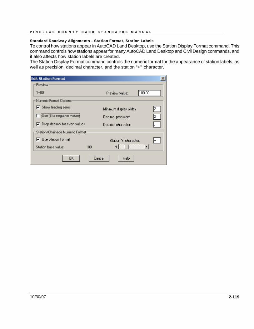
P I N E L L A S C O U N T Y C A D D S T A N D A R D S M A N U A L
10/30/07
Standard Roadway Alignments – Station Format, Station Labels To control how stations appear in AutoCAD Land Desktop, use the Station Display Format command. This command controls how stations appear for many AutoCAD Land Desktop and Civil Design commands, and it also affects how station labels are created. The Station Display Format command controls the numeric format for the appearance of station labels, as well as precision, decimal character, and the station “+” character.
2-119
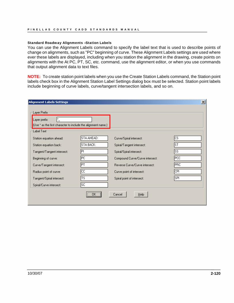
P I N E L L A S C O U N T Y C A D D S T A N D A R D S M A N U A L
10/30/07
Standard Roadway Alignments –Station Labels You can use the Alignment Labels command to specify the label text that is used to describe points of change on alignments, such as "PC" beginning of curve. These Alignment Labels settings are used where ever these labels are displayed, including when you station the alignment in the drawing, create points on alignments with the At PC, PT, SC, etc. command, use the alignment editor, or when you use commands that output alignment data to text files. NOTE: To create station point labels when you use the Create Station Labels command, the Station point labels check box in the Alignment Station Label Settings dialog box must be selected. Station point labels include beginning of curve labels, curve/tangent intersection labels, and so on.
2-120
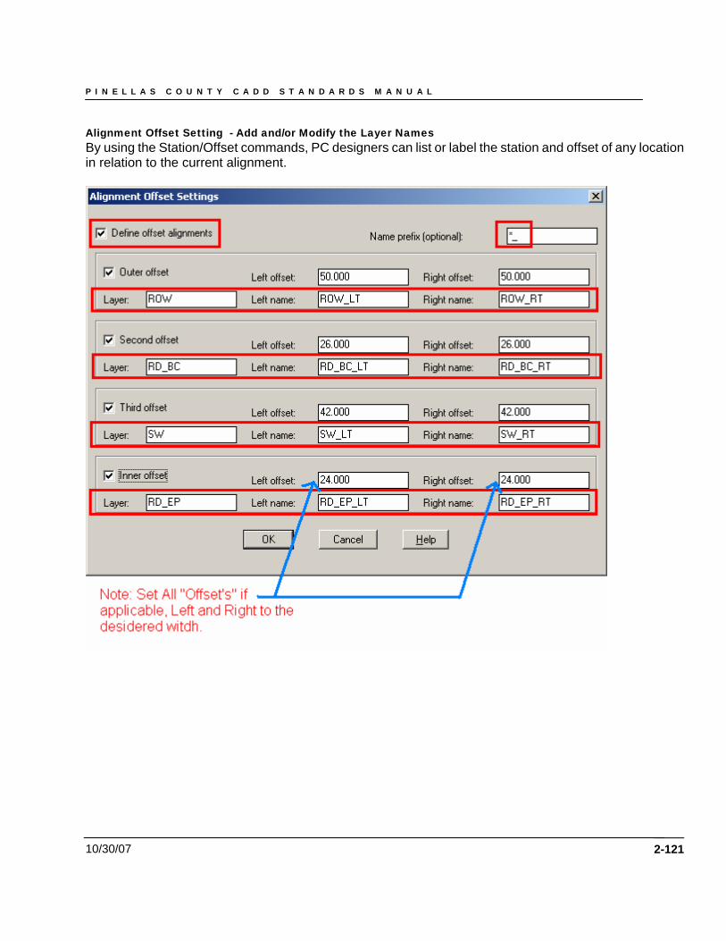
P I N E L L A S C O U N T Y C A D D S T A N D A R D S M A N U A L
10/30/07
Alignment Offset Setting - Add and/or Modify the Layer Names By using the Station/Offset commands, PC designers can list or label the station and offset of any location in relation to the current alignment.
2-121
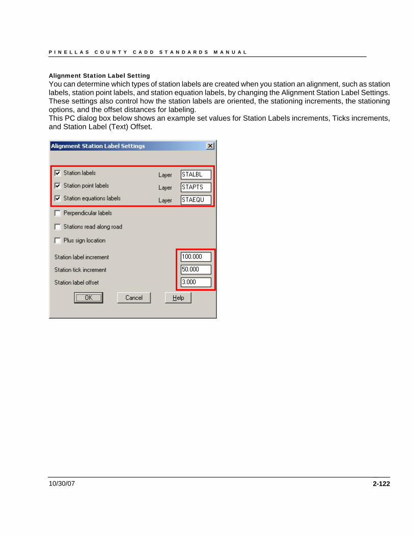
P I N E L L A S C O U N T Y C A D D S T A N D A R D S M A N U A L
10/30/07
Alignment Station Label Setting You can determine which types of station labels are created when you station an alignment, such as station labels, station point labels, and station equation labels, by changing the Alignment Station Label Settings. These settings also control how the station labels are oriented, the stationing increments, the stationing options, and the offset distances for labeling. This PC dialog box below shows an example set values for Station Labels increments, Ticks increments, and Station Label (Text) Offset.
2-122
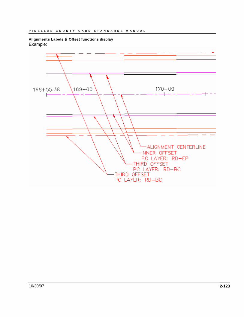
P I N E L L A S C O U N T Y C A D D S T A N D A R D S M A N U A L
10/30/07
Alignments Labels & Offset functions display Example:
2-123
P I N E L L A S C O U N T Y C A D D S T A N D A R D S M A N U A L
10/30/07 2-124
Engineering Roadway Template Alignments Roadway Template Alignments – Description of function A template is a typical section of the finished design elements such as asphalt, concrete, and Base & Sub-Base materials. Templates are made up of two basic elements: normal surfaces and subgrade surfaces. Normal surfaces are the elements of the template that make up the main part of the template such as pavement surfaces, median islands, shoulders and curbs. Subgrade surfaces are linked to the normal surfaces, but use separate design parameters to control the grade and depth of the surface. A typical subgrade surface is made up of granular substances such as lime rock, compacted dirt & gravel. All templates have a defined finished ground reference point which is used by the Edit Design Control command to position the template on the cross section using the horizontal alignment and the finished ground vertical alignment (the FGC profile) for control. This reference point is usually the crown of the roadway. After drawing the template, use the Define Template command to define it. You see different prompts when you use this command, depending on whether the template you are defining is composed of normal or subgrade surfaces. When defining a template with only normal surfaces, you are required to specify a finished ground reference point, a datum line, and connection-points-out. There is also an option to add subassemblies to the template definition. If you are defining a template with a subgrade surface, then you are not prompted to define the connection points, a datum line, or to attach subassemblies. The connection points are defined automatically at the outer end of the drawn portion of the subgrade and the datum lines are automatically generated along the bottom of each subgrade. Each datum line is numbered in ascending order, starting from the lowest subgrade on the template. Before defining templates, be sure to do the following tasks:
• Set the template storage path with the Set Template Path command. This path shall be mapped he the following folder “Rdtplates” in your current project .
• PC Standard roadway template will be in the “Rdtplates” folder, select the prepare section for your roadway design
• Additional templates can be created and stored in this folder. Draw the template surfaces as 2D polylines, either with the Draw Template command or the AutoCAD PLINE command. If this template is one that will be used on other project, you shall submit them to the Capital Support Division office for review and approval.
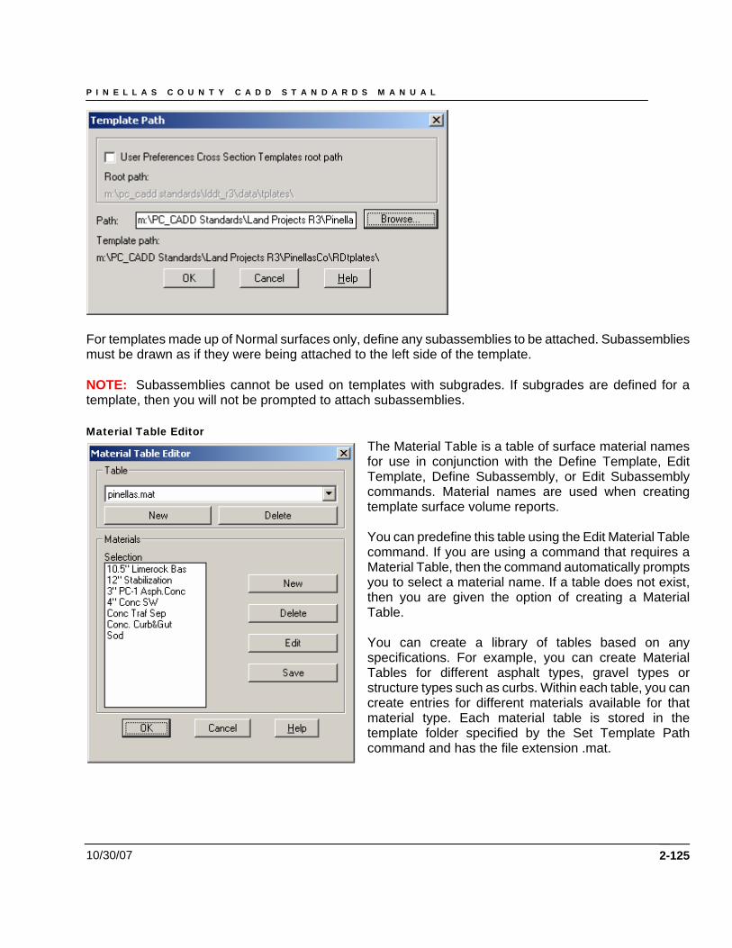
P I N E L L A S C O U N T Y C A D D S T A N D A R D S M A N U A L
10/30/07
For templates made up of Normal surfaces only, define any subassemblies to be attached. Subassemblies must be drawn as if they were being attached to the left side of the template. NOTE: Subassemblies cannot be used on templates with subgrades. If subgrades are defined for a template, then you will not be prompted to attach subassemblies. Material Table Editor
The Material Table is a table of surface material names for use in conjunction with the Define Template, Edit Template, Define Subassembly, or Edit Subassembly commands. Material names are used when creating template surface volume reports. You can predefine this table using the Edit Material Table command. If you are using a command that requires a Material Table, then the command automatically prompts you to select a material name. If a table does not exist, then you are given the option of creating a Material Table. You can create a library of tables based on any specifications. For example, you can create Material Tables for different asphalt types, gravel types or structure types such as curbs. Within each table, you can create entries for different materials available for that material type. Each material table is stored in the template folder specified by the Set Template Path command and has the file extension .mat.
2-125
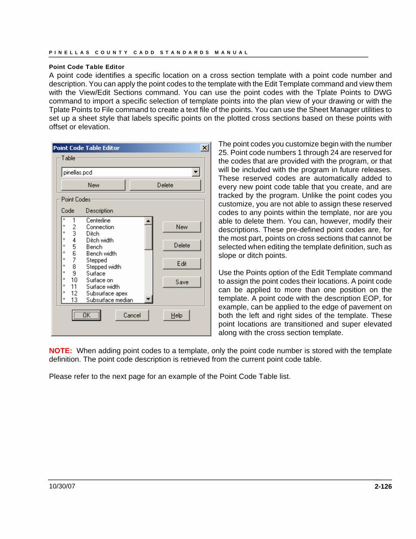
P I N E L L A S C O U N T Y C A D D S T A N D A R D S M A N U A L
10/30/07
Point Code Table Editor A point code identifies a specific location on a cross section template with a point code number and description. You can apply the point codes to the template with the Edit Template command and view them with the View/Edit Sections command. You can use the point codes with the Tplate Points to DWG command to import a specific selection of template points into the plan view of your drawing or with the Tplate Points to File command to create a text file of the points. You can use the Sheet Manager utilities to set up a sheet style that labels specific points on the plotted cross sections based on these points with offset or elevation.
The point codes you customize begin with the number 25. Point code numbers 1 through 24 are reserved for the codes that are provided with the program, or that will be included with the program in future releases. These reserved codes are automatically added to every new point code table that you create, and are tracked by the program. Unlike the point codes you customize, you are not able to assign these reserved codes to any points within the template, nor are you able to delete them. You can, however, modify their descriptions. These pre-defined point codes are, for the most part, points on cross sections that cannot be selected when editing the template definition, such as slope or ditch points. Use the Points option of the Edit Template command to assign the point codes their locations. A point code can be applied to more than one position on the template. A point code with the description EOP, for example, can be applied to the edge of pavement on both the left and right sides of the template. These point locations are transitioned and super elevated along with the cross section template.
NOTE: When adding point codes to a template, only the point code number is stored with the template definition. The point code description is retrieved from the current point code table. Please refer to the next page for an example of the Point Code Table list.
2-126
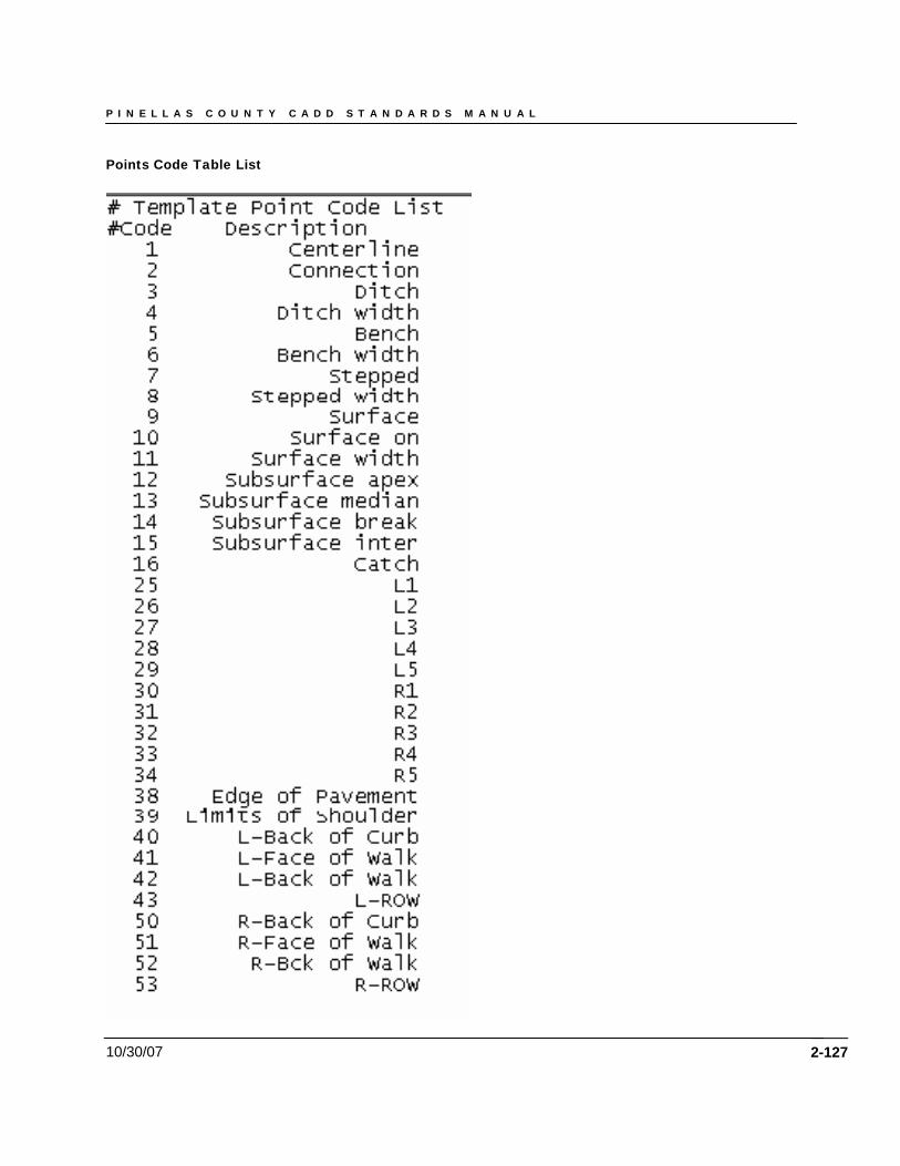
P I N E L L A S C O U N T Y C A D D S T A N D A R D S M A N U A L
10/30/07
Points Code Table List
2-127
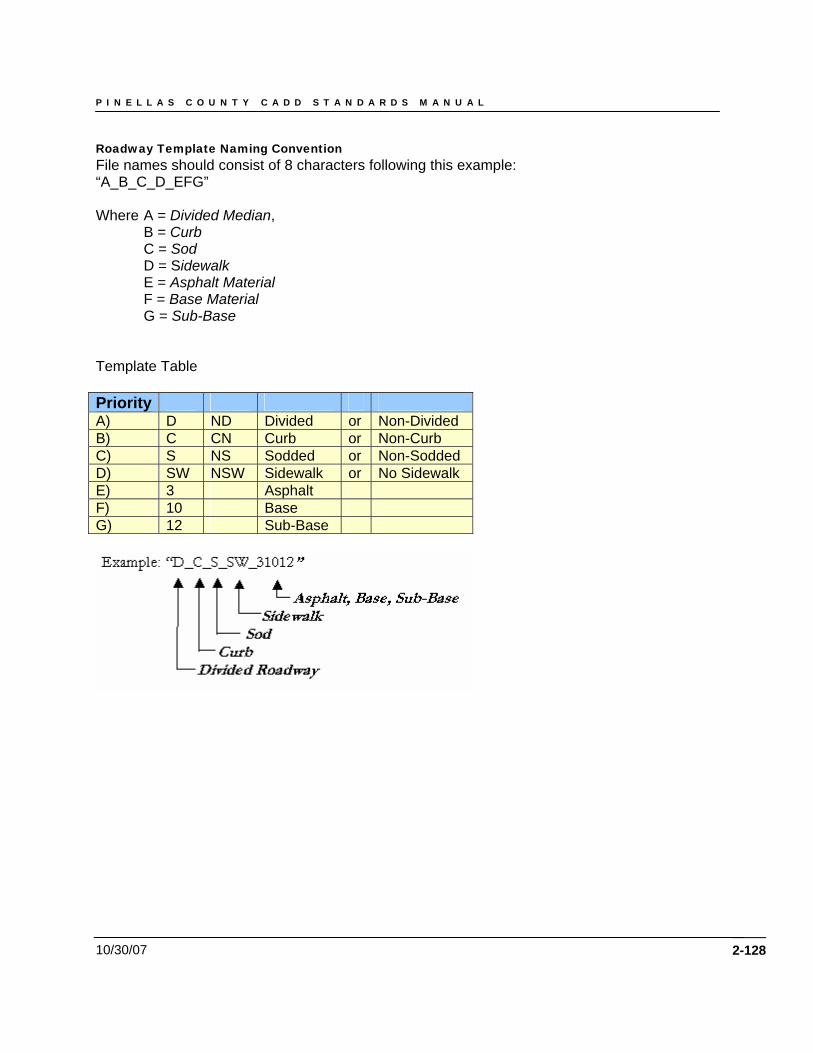
P I N E L L A S C O U N T Y C A D D S T A N D A R D S M A N U A L
10/30/07
Roadway Template Naming Convention File names should consist of 8 characters following this example: “A_B_C_D_EFG” Where A = Divided Median,
B = Curb C = Sod D = Sidewalk
E = Asphalt Material F = Base Material G = Sub-Base Template Table Priority A)
2-128
D ND Divided or Non-Divided B) C CN Curb or Non-Curb C) S NS Sodded or Non-Sodded D) SW NSW Sidewalk or No Sidewalk E) 3 Asphalt F) 10 Base G) 12 Sub-Base
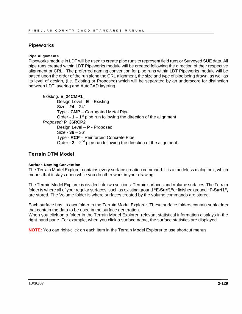
P I N E L L A S C O U N T Y C A D D S T A N D A R D S M A N U A L
10/30/07 2-129
Pipeworks Pipe Alignments Pipeworks module in LDT will be used to create pipe runs to represent field runs or Surveyed SUE data. All pipe runs created within LDT Pipeworks module will be created following the direction of their respective alignment or CRL. The preferred naming convention for pipe runs within LDT Pipeworks module will be based upon the order of the run along the CRL alignment, the size and type of pipe being drawn, as well as its level of design, (i.e. Existing or Proposed) which will be separated by an underscore for distinction between LDT layering and AutoCAD layering.
Existing: E_24CMP1_ Design Level - E – Existing Size - 24 – 24” Type - CMP – Corrugated Metal Pipe Order - 1 – 1st pipe run following the direction of the alignment
Proposed: P_36RCP2_ Design Level – P - Proposed Size - 36 – 36” Type - RCP – Reinforced Concrete Pipe Order - 2 – 2nd pipe run following the direction of the alignment
Terrain DTM Model Surface Naming Convention The Terrain Model Explorer contains every surface creation command. It is a modeless dialog box, which means that it stays open while you do other work in your drawing. The Terrain Model Explorer is divided into two sections: Terrain surfaces and Volume surfaces. The Terrain folder is where all of your regular surfaces, such as existing ground “E-Surf1”or finished ground “P-Surf1”, are stored. The Volume folder is where surfaces created by the volume commands are stored. Each surface has its own folder in the Terrain Model Explorer. These surface folders contain subfolders that contain the data to be used in the surface generation. When you click on a folder in the Terrain Model Explorer, relevant statistical information displays in the right-hand pane. For example, when you click a surface name, the surface statistics are displayed. NOTE: You can right-click on each item in the Terrain Model Explorer to use shortcut menus.
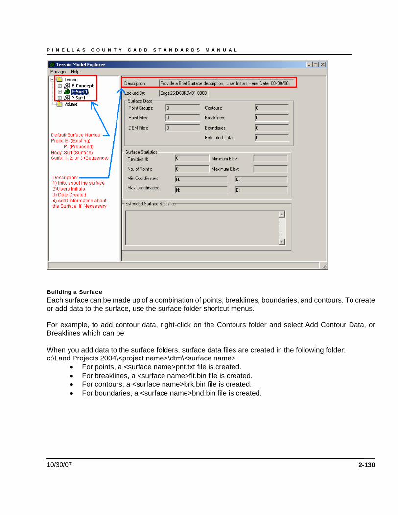
P I N E L L A S C O U N T Y C A D D S T A N D A R D S M A N U A L
10/30/07
Building a Surface Each surface can be made up of a combination of points, breaklines, boundaries, and contours. To create or add data to the surface, use the surface folder shortcut menus. For example, to add contour data, right-click on the Contours folder and select Add Contour Data, or Breaklines which can be When you add data to the surface folders, surface data files are created in the following folder: c:\Land Projects 2004\<project name>\dtm\<surface name>
• For points, a <surface name>pnt.txt file is created. • For breaklines, a <surface name>flt.bin file is created. • For contours, a <surface name>brk.bin file is created. • For boundaries, a <surface name>bnd.bin file is created.
2-130
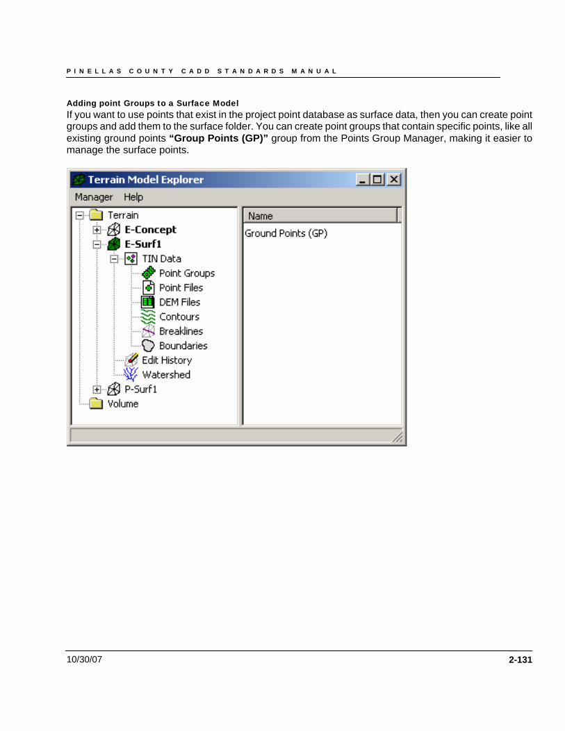
P I N E L L A S C O U N T Y C A D D S T A N D A R D S M A N U A L
10/30/07
Adding point Groups to a Surface Model If you want to use points that exist in the project point database as surface data, then you can create point groups and add them to the surface folder. You can create point groups that contain specific points, like all existing ground points “Group Points (GP)” group from the Points Group Manager, making it easier to manage the surface points.
2-131
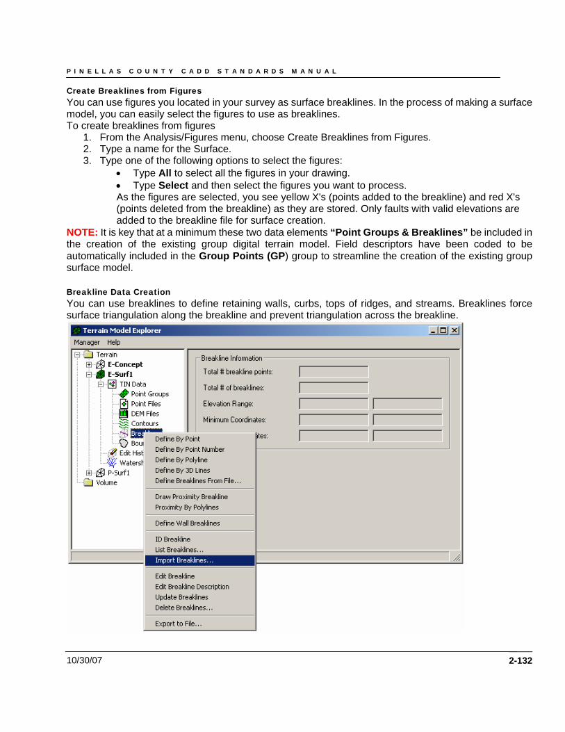
P I N E L L A S C O U N T Y C A D D S T A N D A R D S M A N U A L
10/30/07
Create Breaklines from Figures You can use figures you located in your survey as surface breaklines. In the process of making a surface model, you can easily select the figures to use as breaklines. To create breaklines from figures
1. From the Analysis/Figures menu, choose Create Breaklines from Figures. 2. Type a name for the Surface. 3. Type one of the following options to select the figures:
• Type All to select all the figures in your drawing. • Type Select and then select the figures you want to process. As the figures are selected, you see yellow X's (points added to the breakline) and red X's (points deleted from the breakline) as they are stored. Only faults with valid elevations are added to the breakline file for surface creation.
NOTE: It is key that at a minimum these two data elements “Point Groups & Breaklines” be included in the creation of the existing group digital terrain model. Field descriptors have been coded to be automatically included in the Group Points (GP) group to streamline the creation of the existing group surface model. Breakline Data Creation You can use breaklines to define retaining walls, curbs, tops of ridges, and streams. Breaklines force surface triangulation along the breakline and prevent triangulation across the breakline.
2-132
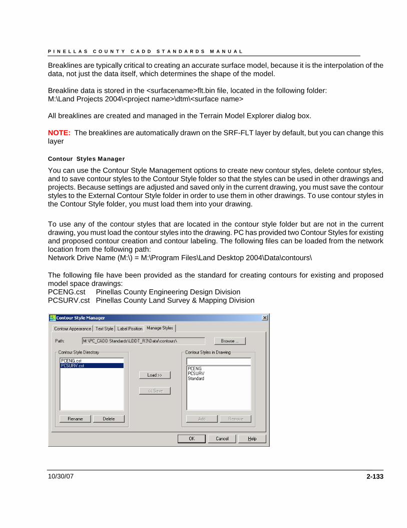
P I N E L L A S C O U N T Y C A D D S T A N D A R D S M A N U A L
10/30/07
Breaklines are typically critical to creating an accurate surface model, because it is the interpolation of the data, not just the data itself, which determines the shape of the model. Breakline data is stored in the <surfacename>flt.bin file, located in the following folder: M:\Land Projects 2004\<project name>\dtm\<surface name> All breaklines are created and managed in the Terrain Model Explorer dialog box. NOTE: The breaklines are automatically drawn on the SRF-FLT layer by default, but you can change this layer Contour Styles Manager
You can use the Contour Style Management options to create new contour styles, delete contour styles, and to save contour styles to the Contour Style folder so that the styles can be used in other drawings and projects. Because settings are adjusted and saved only in the current drawing, you must save the contour styles to the External Contour Style folder in order to use them in other drawings. To use contour styles in the Contour Style folder, you must load them into your drawing. To use any of the contour styles that are located in the contour style folder but are not in the current drawing, you must load the contour styles into the drawing. PC has provided two Contour Styles for existing and proposed contour creation and contour labeling. The following files can be loaded from the network location from the following path: Network Drive Name (M:\) = M:\Program Files\Land Desktop 2004\Data\contours\ The following file have been provided as the standard for creating contours for existing and proposed model space drawings: PCENG.cst Pinellas County Engineering Design Division PCSURV.cst Pinellas County Land Survey & Mapping Division
2-133

P I N E L L A S C O U N T Y C A D D S T A N D A R D S M A N U A L
10/30/07
NOTE: After you create the contour style files using Release 2 of AutoCAD Land Development Desktop, the contour style files may not be used with any prior version of AutoCAD Land Development Desktop. Profiles Use the Profiles commands to create existing ground and finished ground profiles. You can sample a surface, a file, or cross sections to obtain surface data from which to generate the existing ground profile. You can create a full profile with a grid and labels, or you can create a quick profile without vertical grid lines or station elevations. You can also create profiles that represent subsurfaces.
After you create the existing ground profile, you can design the finished ground profile by drawing tangents and vertical curves to represent the finished ground centerline and/or ditches and transitions. Then you can define these tangents and vertical curves as a vertical alignment. After you define a vertical alignment, you can edit the alignment from within the Vertical Alignment Editor. The vertical alignment data is used with the horizontal alignment data to define the finished ground cross sections.
2-134
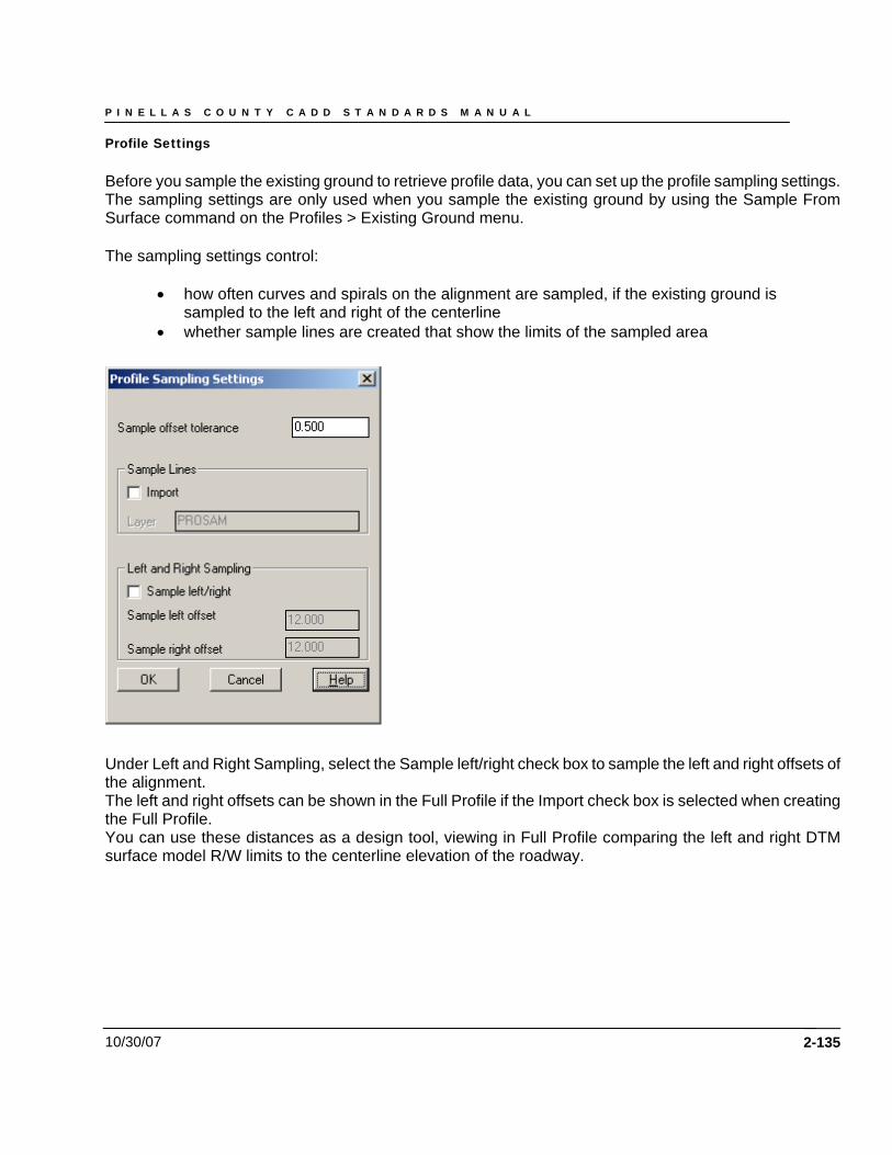
P I N E L L A S C O U N T Y C A D D S T A N D A R D S M A N U A L
10/30/07
Profile Settings Before you sample the existing ground to retrieve profile data, you can set up the profile sampling settings. The sampling settings are only used when you sample the existing ground by using the Sample From Surface command on the Profiles > Existing Ground menu. The sampling settings control:
• how often curves and spirals on the alignment are sampled, if the existing ground is sampled to the left and right of the centerline
• whether sample lines are created that show the limits of the sampled area
Under Left and Right Sampling, select the Sample left/right check box to sample the left and right offsets of the alignment. The left and right offsets can be shown in the Full Profile if the Import check box is selected when creating the Full Profile. You can use these distances as a design tool, viewing in Full Profile comparing the left and right DTM surface model R/W limits to the centerline elevation of the roadway.
2-135
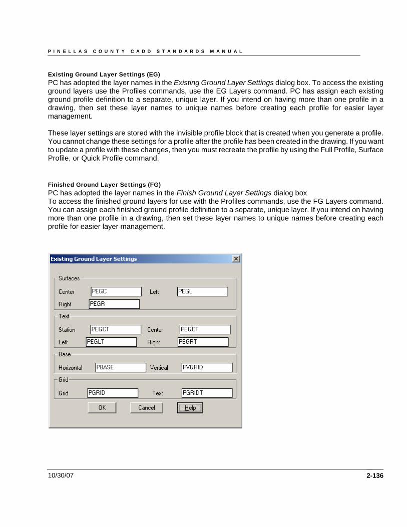
P I N E L L A S C O U N T Y C A D D S T A N D A R D S M A N U A L
10/30/07
Existing Ground Layer Settings (EG) PC has adopted the layer names in the Existing Ground Layer Settings dialog box. To access the existing ground layers use the Profiles commands, use the EG Layers command. PC has assign each existing ground profile definition to a separate, unique layer. If you intend on having more than one profile in a drawing, then set these layer names to unique names before creating each profile for easier layer management. These layer settings are stored with the invisible profile block that is created when you generate a profile. You cannot change these settings for a profile after the profile has been created in the drawing. If you want to update a profile with these changes, then you must recreate the profile by using the Full Profile, Surface Profile, or Quick Profile command. Finished Ground Layer Settings (FG) PC has adopted the layer names in the Finish Ground Layer Settings dialog box To access the finished ground layers for use with the Profiles commands, use the FG Layers command. You can assign each finished ground profile definition to a separate, unique layer. If you intend on having more than one profile in a drawing, then set these layer names to unique names before creating each profile for easier layer management.
2-136
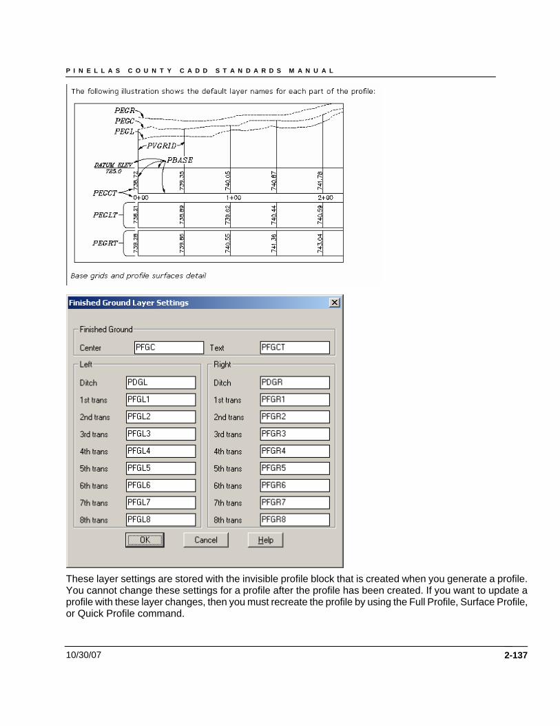
P I N E L L A S C O U N T Y C A D D S T A N D A R D S M A N U A L
10/30/07
These layer settings are stored with the invisible profile block that is created when you generate a profile. You cannot change these settings for a profile after the profile has been created. If you want to update a profile with these layer changes, then you must recreate the profile by using the Full Profile, Surface Profile, or Quick Profile command.
2-137
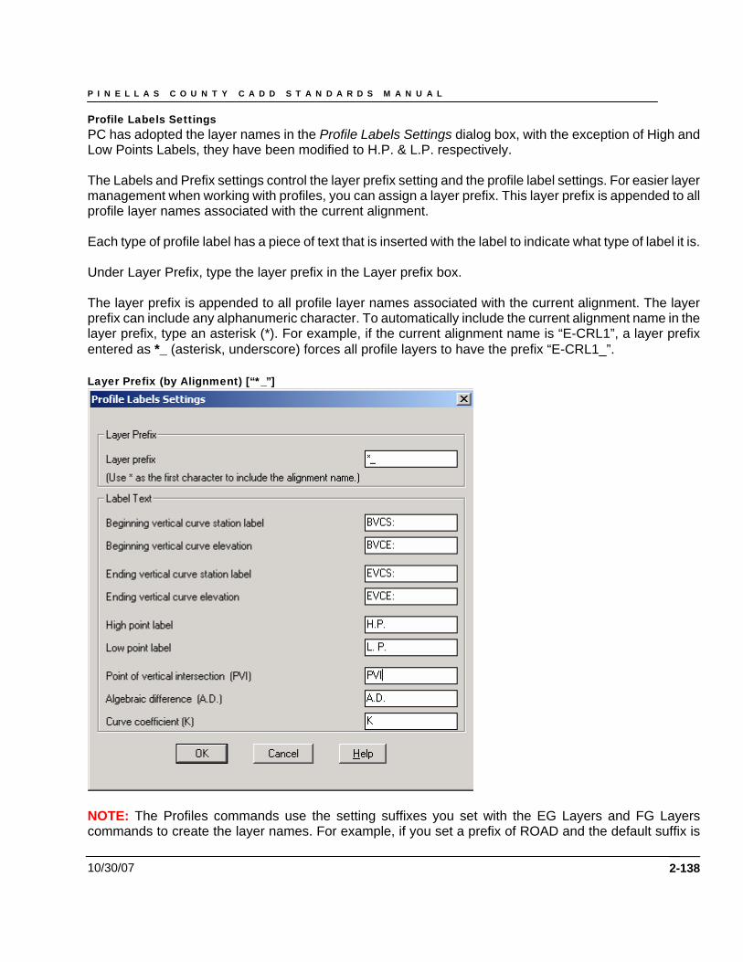
P I N E L L A S C O U N T Y C A D D S T A N D A R D S M A N U A L
10/30/07
Profile Labels Settings PC has adopted the layer names in the Profile Labels Settings dialog box, with the exception of High and Low Points Labels, they have been modified to H.P. & L.P. respectively. The Labels and Prefix settings control the layer prefix setting and the profile label settings. For easier layer management when working with profiles, you can assign a layer prefix. This layer prefix is appended to all profile layer names associated with the current alignment. Each type of profile label has a piece of text that is inserted with the label to indicate what type of label it is. Under Layer Prefix, type the layer prefix in the Layer prefix box. The layer prefix is appended to all profile layer names associated with the current alignment. The layer prefix can include any alphanumeric character. To automatically include the current alignment name in the layer prefix, type an asterisk (*). For example, if the current alignment name is “E-CRL1”, a layer prefix entered as *_ (asterisk, underscore) forces all profile layers to have the prefix “E-CRL1_”. Layer Prefix (by Alignment) [“*_”]
NOTE: The Profiles commands use the setting suffixes you set with the EG Layers and FG Layers commands to create the layer names. For example, if you set a prefix of ROAD and the default suffix is
2-138
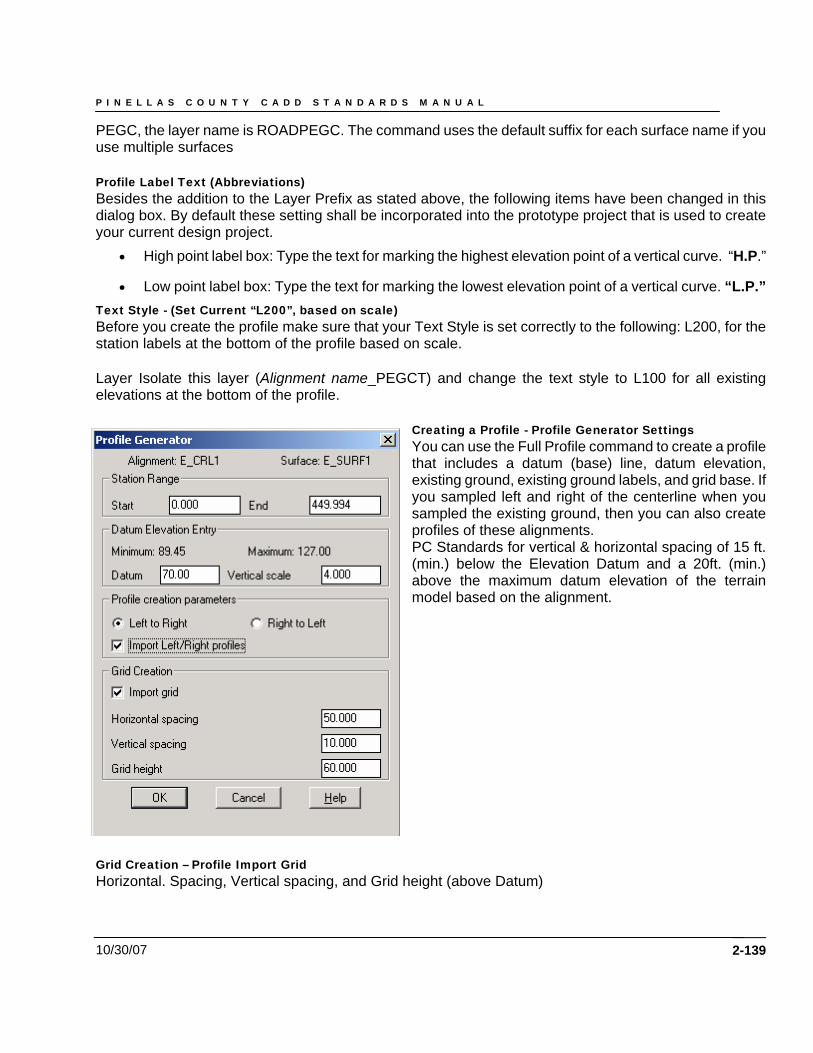
P I N E L L A S C O U N T Y C A D D S T A N D A R D S M A N U A L
10/30/07
PEGC, the layer name is ROADPEGC. The command uses the default suffix for each surface name if you use multiple surfaces Profile Label Text (Abbreviations) Besides the addition to the Layer Prefix as stated above, the following items have been changed in this dialog box. By default these setting shall be incorporated into the prototype project that is used to create your current design project.
• High point label box: Type the text for marking the highest elevation point of a vertical curve. “H.P.”
• Low point label box: Type the text for marking the lowest elevation point of a vertical curve. “L.P.” Text Style - (Set Current “L200”, based on scale) Before you create the profile make sure that your Text Style is set correctly to the following: L200, for the station labels at the bottom of the profile based on scale. Layer Isolate this layer (Alignment name_PEGCT) and change the text style to L100 for all existing elevations at the bottom of the profile.
Creating a Profile - Profile Generator Settings You can use the Full Profile command to create a profile that includes a datum (base) line, datum elevation, existing ground, existing ground labels, and grid base. If you sampled left and right of the centerline when you sampled the existing ground, then you can also create profiles of these alignments. PC Standards for vertical & horizontal spacing of 15 ft. (min.) below the Elevation Datum and a 20ft. (min.) above the maximum datum elevation of the terrain model based on the alignment.
Grid Creation – Profile Import Grid Horizontal. Spacing, Vertical spacing, and Grid height (above Datum)
2-139
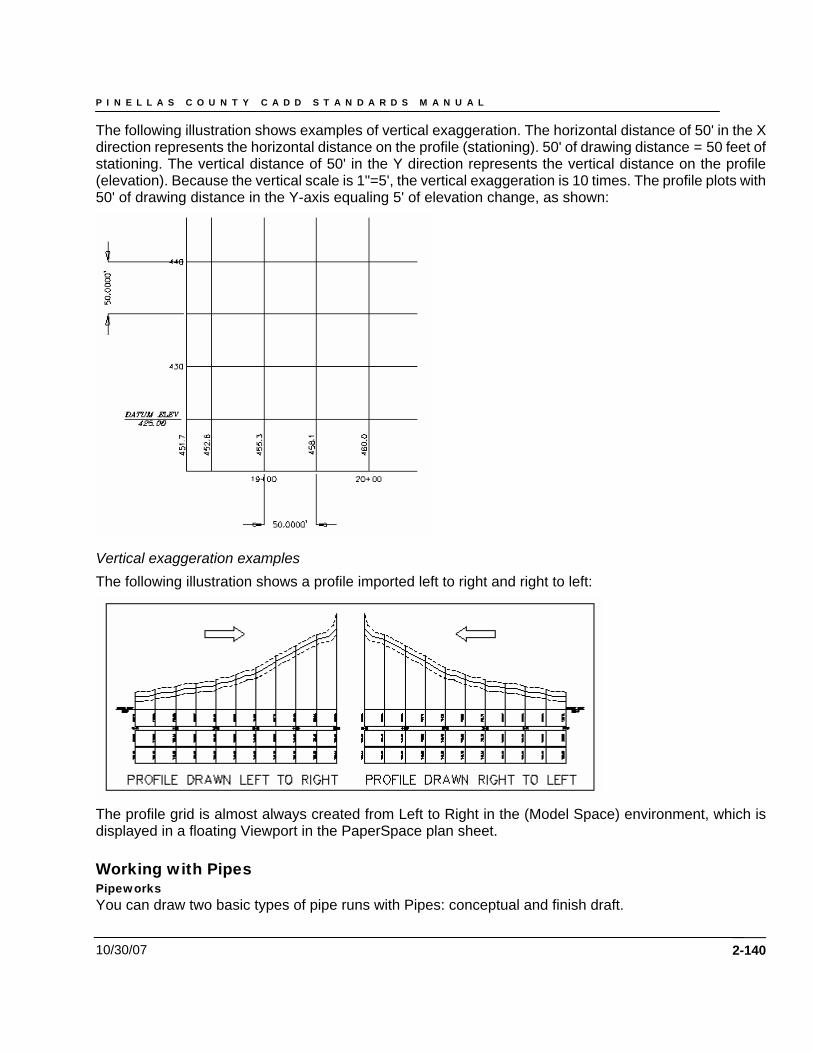
P I N E L L A S C O U N T Y C A D D S T A N D A R D S M A N U A L
10/30/07
The following illustration shows examples of vertical exaggeration. The horizontal distance of 50' in the X direction represents the horizontal distance on the profile (stationing). 50' of drawing distance = 50 feet of stationing. The vertical distance of 50' in the Y direction represents the vertical distance on the profile (elevation). Because the vertical scale is 1"=5', the vertical exaggeration is 10 times. The profile plots with 50' of drawing distance in the Y-axis equaling 5' of elevation change, as shown:
Vertical exaggeration examples The following illustration shows a profile imported left to right and right to left:
The profile grid is almost always created from Left to Right in the (Model Space) environment, which is displayed in a floating Viewport in the PaperSpace plan sheet. Working with Pipes Pipeworks You can draw two basic types of pipe runs with Pipes: conceptual and finish draft.
2-140
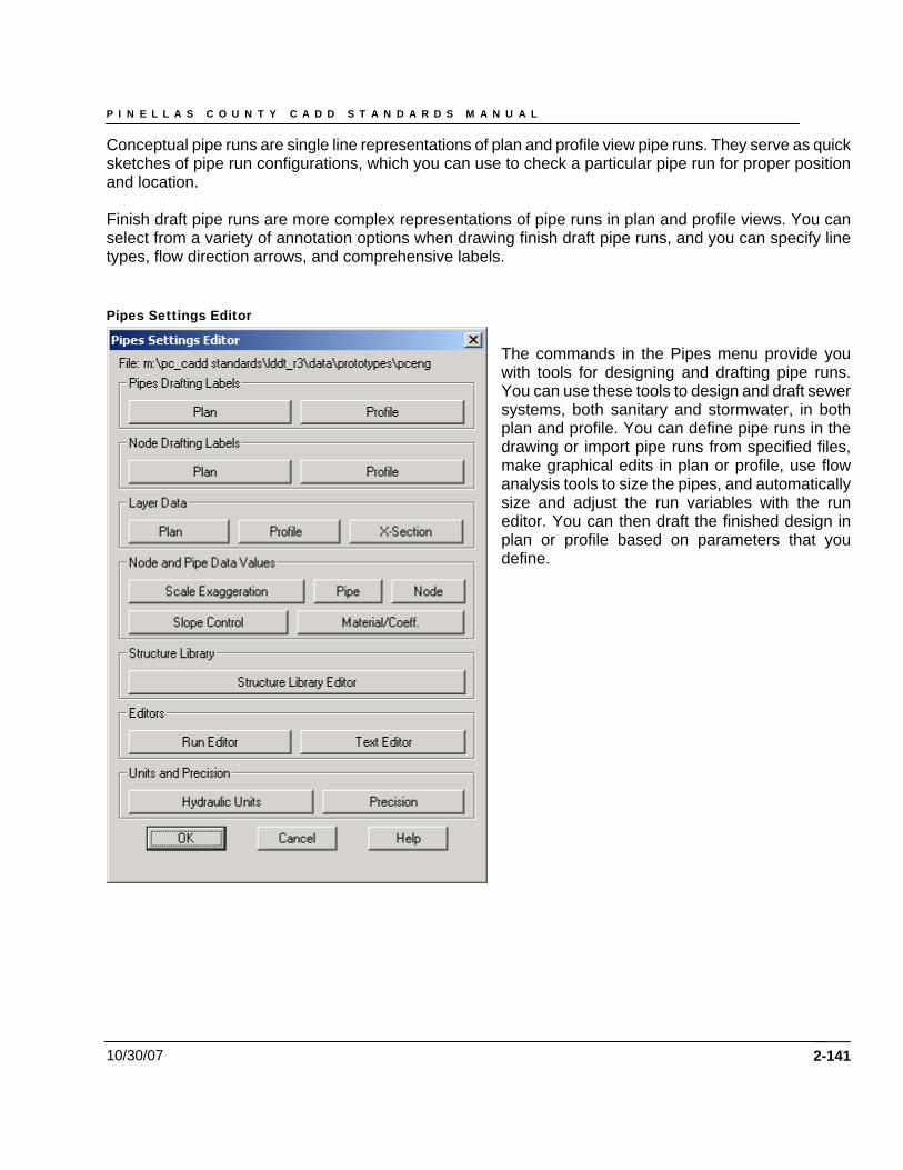
P I N E L L A S C O U N T Y C A D D S T A N D A R D S M A N U A L
10/30/07
Conceptual pipe runs are single line representations of plan and profile view pipe runs. They serve as quick sketches of pipe run configurations, which you can use to check a particular pipe run for proper position and location. Finish draft pipe runs are more complex representations of pipe runs in plan and profile views. You can select from a variety of annotation options when drawing finish draft pipe runs, and you can specify line types, flow direction arrows, and comprehensive labels. Pipes Settings Editor
The commands in the Pipes menu provide you with tools for designing and drafting pipe runs. You can use these tools to design and draft sewer systems, both sanitary and stormwater, in both plan and profile. You can define pipe runs in the drawing or import pipe runs from specified files, make graphical edits in plan or profile, use flow analysis tools to size the pipes, and automatically size and adjust the run variables with the run editor. You can then draft the finished design in plan or profile based on parameters that you define.
2-141
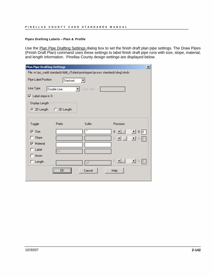
P I N E L L A S C O U N T Y C A D D S T A N D A R D S M A N U A L
10/30/07
Pipes Drafting Labels – Plan & Profile Use the Plan Pipe Drafting Settings dialog box to set the finish draft plan pipe settings. The Draw Pipes (Finish Draft Plan) command uses these settings to label finish draft pipe runs with size, slope, material, and length information. Pinellas County design settings are displayed below.
2-142
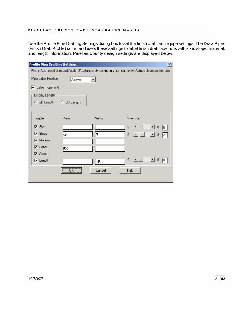
P I N E L L A S C O U N T Y C A D D S T A N D A R D S M A N U A L
10/30/07
Use the Profile Pipe Drafting Settings dialog box to set the finish draft profile pipe settings. The Draw Pipes (Finish Draft Profile) command uses these settings to label finish draft pipe runs with size, slope, material, and length information. Pinellas County design settings are displayed below.
2-143
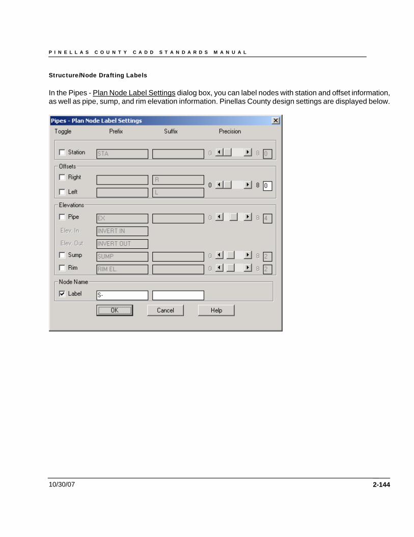
P I N E L L A S C O U N T Y C A D D S T A N D A R D S M A N U A L
10/30/07
Structure/Node Drafting Labels In the Pipes - Plan Node Label Settings dialog box, you can label nodes with station and offset information, as well as pipe, sump, and rim elevation information. Pinellas County design settings are displayed below.
2-144
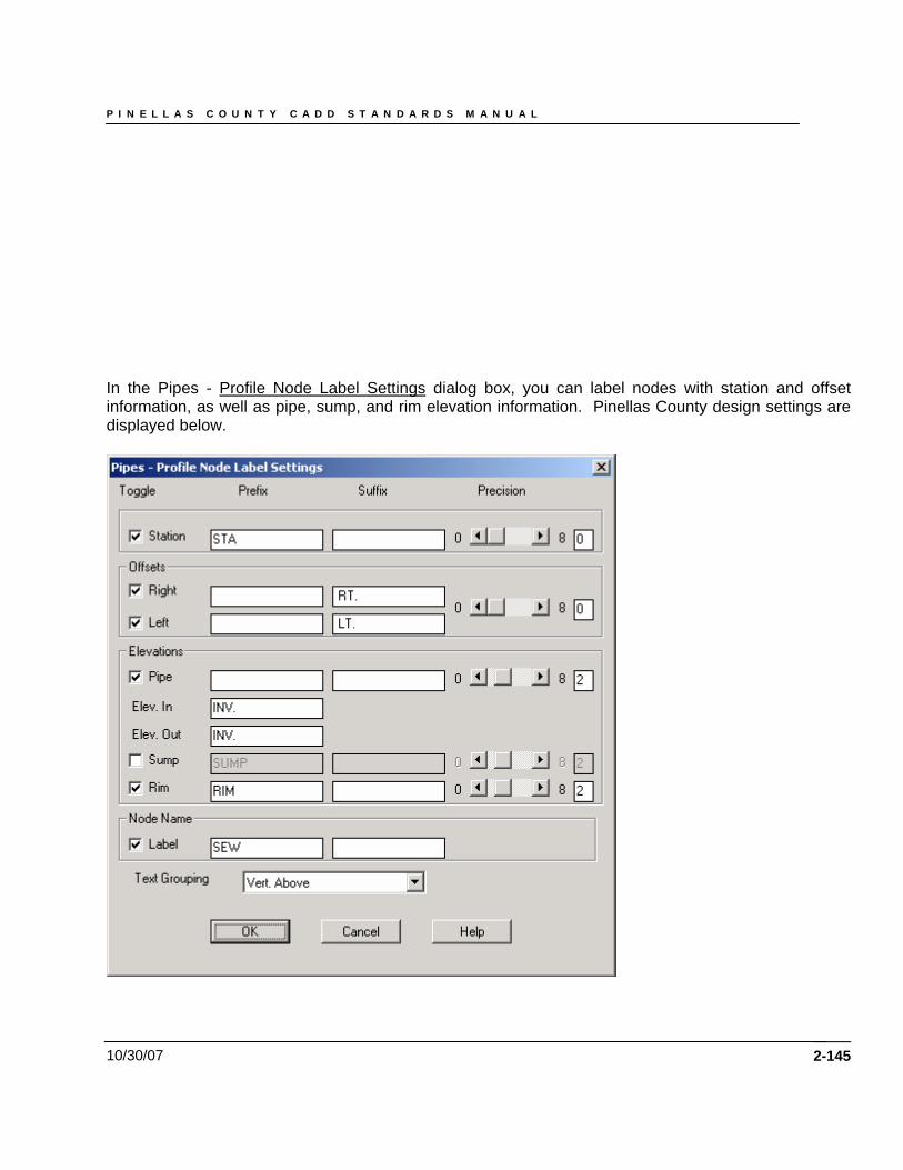
P I N E L L A S C O U N T Y C A D D S T A N D A R D S M A N U A L
10/30/07
In the Pipes - Profile Node Label Settings dialog box, you can label nodes with station and offset information, as well as pipe, sump, and rim elevation information. Pinellas County design settings are displayed below.
2-145
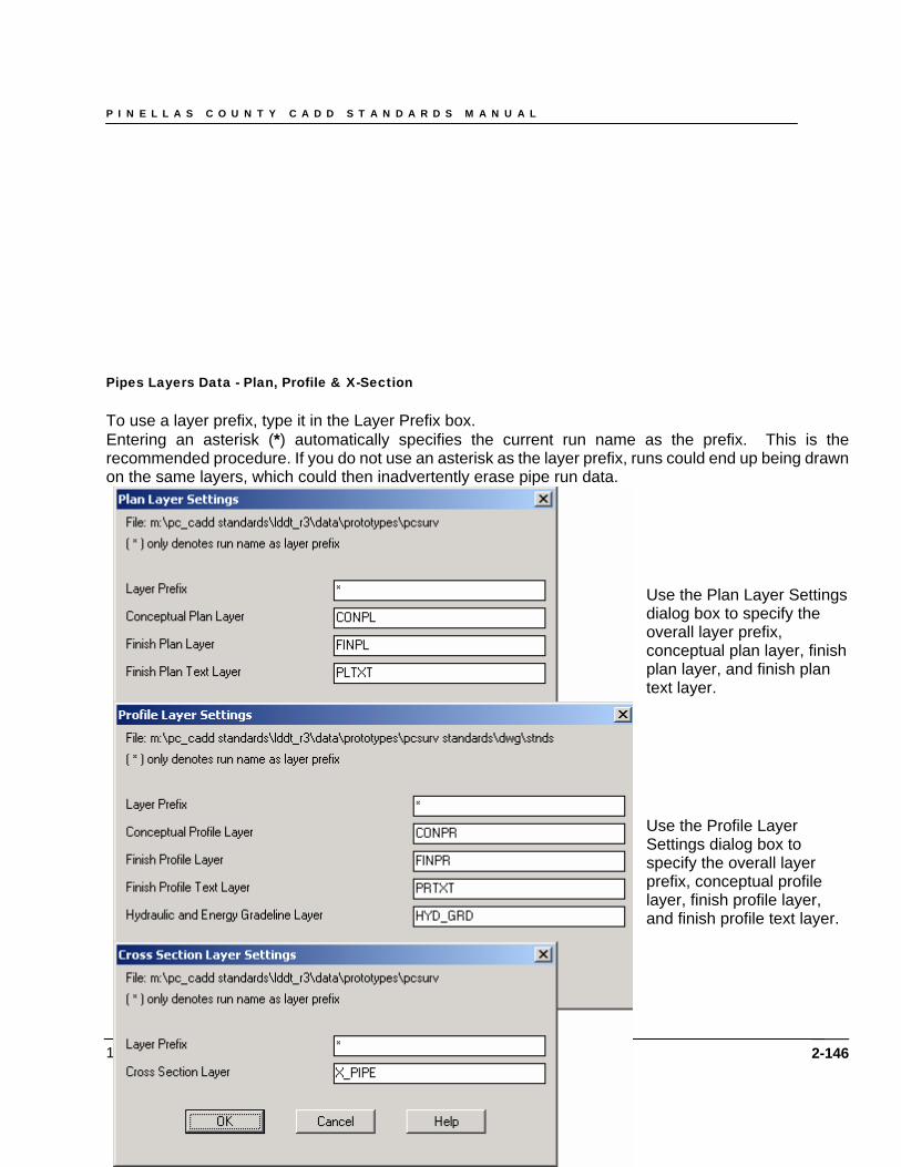
P I N E L L A S C O U N T Y C A D D S T A N D A R D S M A N U A L
10/30/07
Pipes Layers Data - Plan, Profile & X-Section To use a layer prefix, type it in the Layer Prefix box. Entering an asterisk (*) automatically specifies the current run name as the prefix. This is the recommended procedure. If you do not use an asterisk as the layer prefix, runs could end up being drawn on the same layers, which could then inadvertently erase pipe run data.
Use the Plan Layer Settings dialog box to specify the overall layer prefix, conceptual plan layer, finish plan layer, and finish plan text layer. Use the Profile Layer Settings dialog box to specify the overall layer prefix, conceptual profile layer, finish profile layer, and finish profile text layer.
2-146
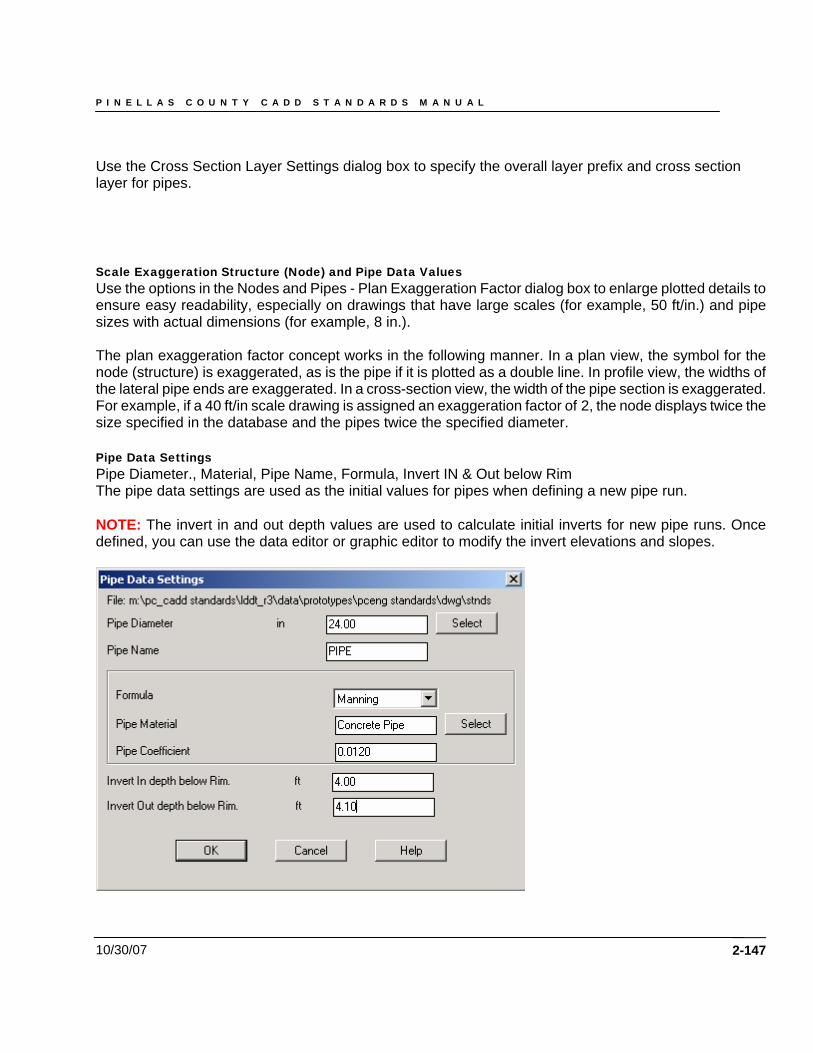
P I N E L L A S C O U N T Y C A D D S T A N D A R D S M A N U A L
10/30/07
Use the Cross Section Layer Settings dialog box to specify the overall layer prefix and cross section layer for pipes. Scale Exaggeration Structure (Node) and Pipe Data Values Use the options in the Nodes and Pipes - Plan Exaggeration Factor dialog box to enlarge plotted details to ensure easy readability, especially on drawings that have large scales (for example, 50 ft/in.) and pipe sizes with actual dimensions (for example, 8 in.). The plan exaggeration factor concept works in the following manner. In a plan view, the symbol for the node (structure) is exaggerated, as is the pipe if it is plotted as a double line. In profile view, the widths of the lateral pipe ends are exaggerated. In a cross-section view, the width of the pipe section is exaggerated. For example, if a 40 ft/in scale drawing is assigned an exaggeration factor of 2, the node displays twice the size specified in the database and the pipes twice the specified diameter. Pipe Data Settings Pipe Diameter., Material, Pipe Name, Formula, Invert IN & Out below Rim The pipe data settings are used as the initial values for pipes when defining a new pipe run. NOTE: The invert in and out depth values are used to calculate initial inverts for new pipe runs. Once defined, you can use the data editor or graphic editor to modify the invert elevations and slopes.
2-147
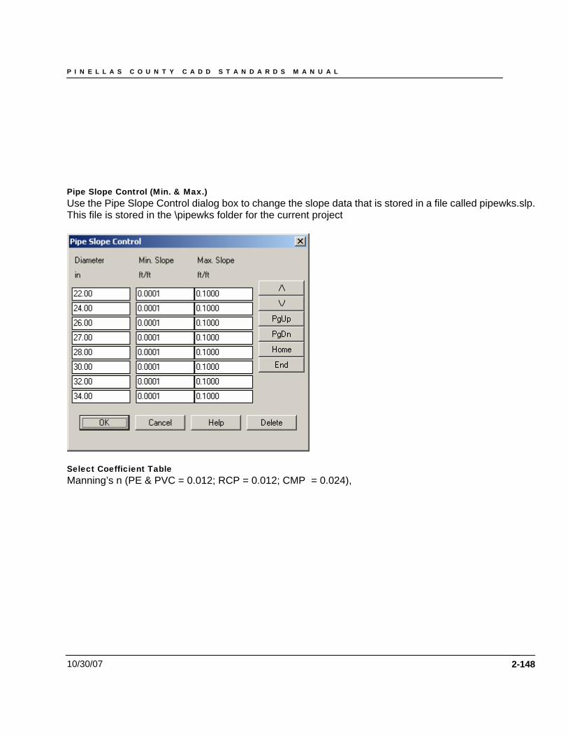
P I N E L L A S C O U N T Y C A D D S T A N D A R D S M A N U A L
10/30/07
Pipe Slope Control (Min. & Max.) Use the Pipe Slope Control dialog box to change the slope data that is stored in a file called pipewks.slp. This file is stored in the \pipewks folder for the current project
Select Coefficient Table Manning’s n (PE & PVC = 0.012; RCP = 0.012; CMP = 0.024),
2-148
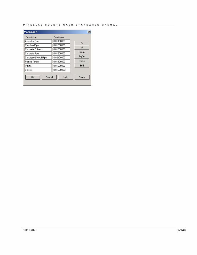
P I N E L L A S C O U N T Y C A D D S T A N D A R D S M A N U A L
10/30/07 2-149
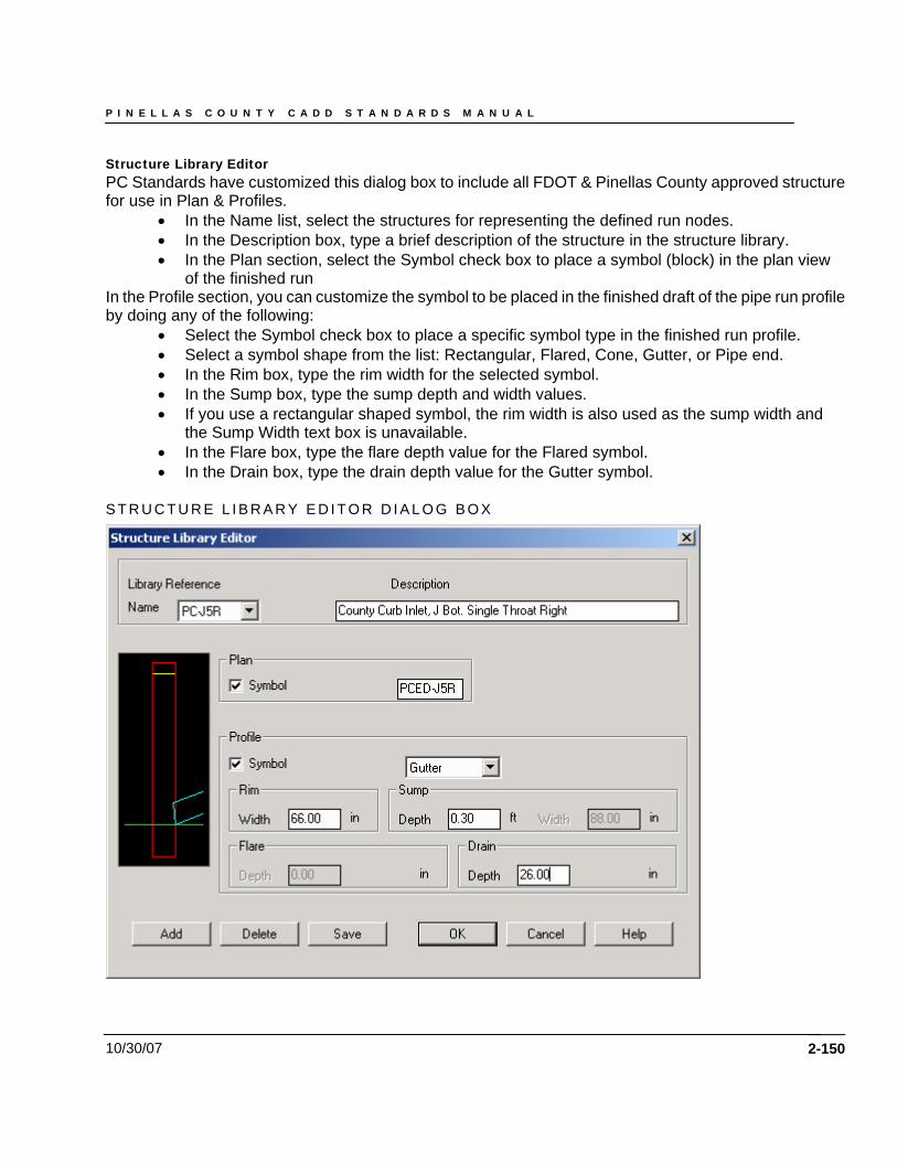
P I N E L L A S C O U N T Y C A D D S T A N D A R D S M A N U A L
10/30/07
Structure Library Editor PC Standards have customized this dialog box to include all FDOT & Pinellas County approved structure for use in Plan & Profiles.
• In the Name list, select the structures for representing the defined run nodes. • In the Description box, type a brief description of the structure in the structure library. • In the Plan section, select the Symbol check box to place a symbol (block) in the plan view
of the finished run In the Profile section, you can customize the symbol to be placed in the finished draft of the pipe run profile by doing any of the following:
• Select the Symbol check box to place a specific symbol type in the finished run profile. • Select a symbol shape from the list: Rectangular, Flared, Cone, Gutter, or Pipe end. • In the Rim box, type the rim width for the selected symbol. • In the Sump box, type the sump depth and width values. • If you use a rectangular shaped symbol, the rim width is also used as the sump width and
the Sump Width text box is unavailable. • In the Flare box, type the flare depth value for the Flared symbol. • In the Drain box, type the drain depth value for the Gutter symbol.
S T R U C T U R E L I B R A R Y E D I T O R D I A L O G B O X
2-150
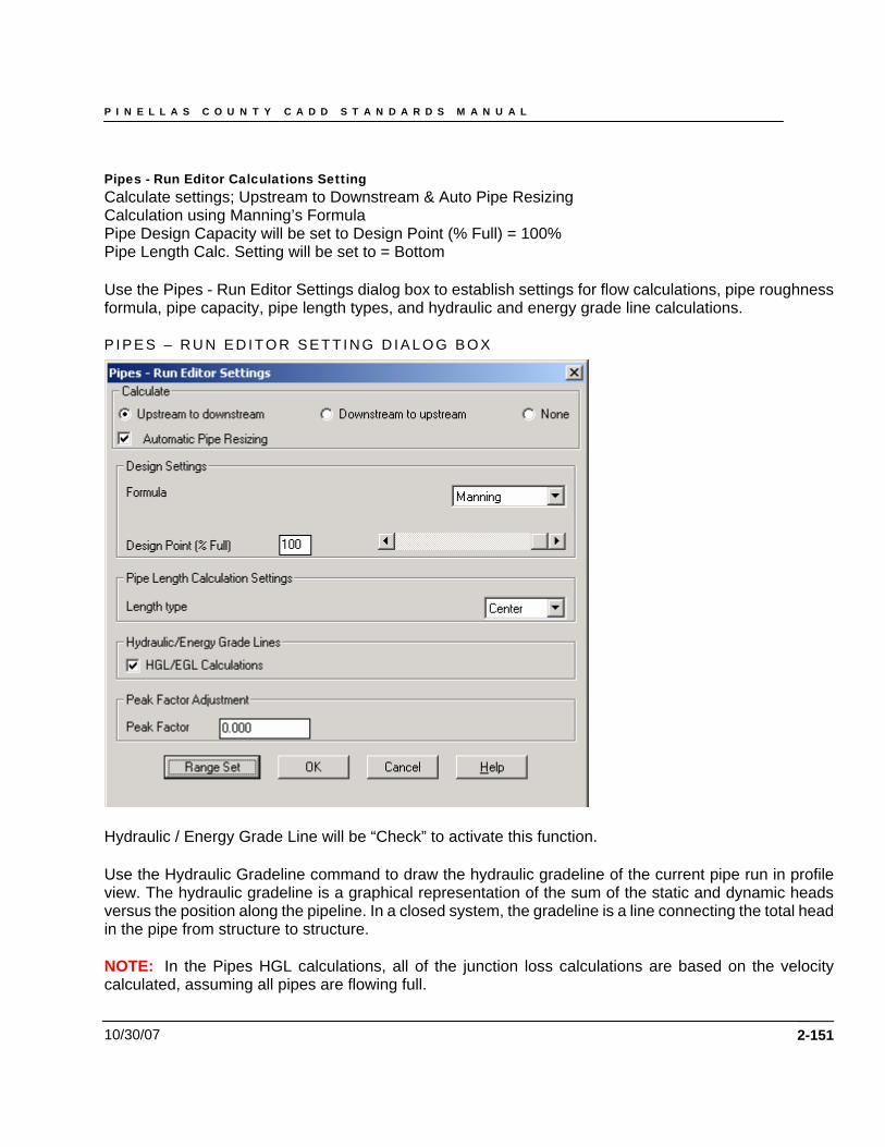
P I N E L L A S C O U N T Y C A D D S T A N D A R D S M A N U A L
10/30/07
Pipes - Run Editor Calculations Setting Calculate settings; Upstream to Downstream & Auto Pipe Resizing Calculation using Manning’s Formula Pipe Design Capacity will be set to Design Point (% Full) = 100% Pipe Length Calc. Setting will be set to = Bottom Use the Pipes - Run Editor Settings dialog box to establish settings for flow calculations, pipe roughness formula, pipe capacity, pipe length types, and hydraulic and energy grade line calculations. P I P E S – R U N E D I T O R S E T T I N G D I A L O G B O X
Hydraulic / Energy Grade Line will be “Check” to activate this function. Use the Hydraulic Gradeline command to draw the hydraulic gradeline of the current pipe run in profile view. The hydraulic gradeline is a graphical representation of the sum of the static and dynamic heads versus the position along the pipeline. In a closed system, the gradeline is a line connecting the total head in the pipe from structure to structure. NOTE: In the Pipes HGL calculations, all of the junction loss calculations are based on the velocity calculated, assuming all pipes are flowing full.
2-151
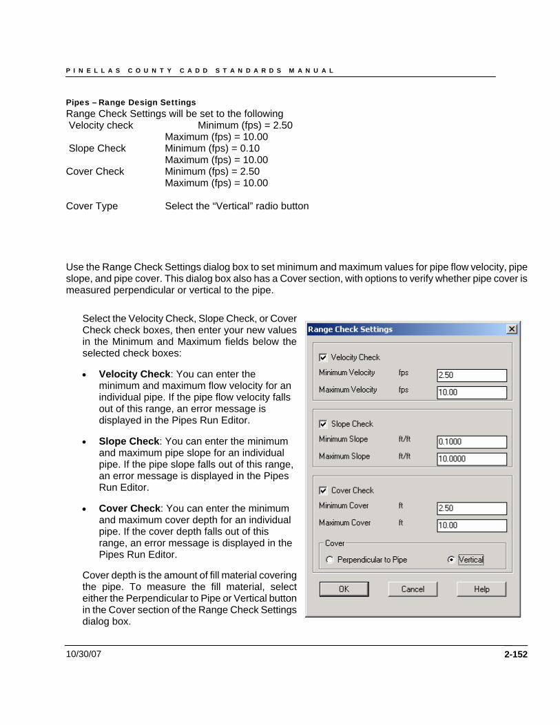
P I N E L L A S C O U N T Y C A D D S T A N D A R D S M A N U A L
10/30/07
Pipes – Range Design Settings Range Check Settings will be set to the following Velocity check Minimum (fps) = 2.50 Maximum (fps) = 10.00 Slope Check Minimum (fps) = 0.10 Maximum (fps) = 10.00 Cover Check Minimum (fps) = 2.50 Maximum (fps) = 10.00 Cover Type Select the “Vertical” radio button Use the Range Check Settings dialog box to set minimum and maximum values for pipe flow velocity, pipe slope, and pipe cover. This dialog box also has a Cover section, with options to verify whether pipe cover is measured perpendicular or vertical to the pipe.
Select the Velocity Check, Slope Check, or Cover Check check boxes, then enter your new values in the Minimum and Maximum fields below the selected check boxes:
• Velocity Check: You can enter the minimum and maximum flow velocity for an individual pipe. If the pipe flow velocity falls out of this range, an error message is displayed in the Pipes Run Editor.
• Slope Check: You can enter the minimum and maximum pipe slope for an individual pipe. If the pipe slope falls out of this range, an error message is displayed in the Pipes Run Editor.
• Cover Check: You can enter the minimum and maximum cover depth for an individual pipe. If the cover depth falls out of this range, an error message is displayed in the Pipes Run Editor.
Cover depth is the amount of fill material covering the pipe. To measure the fill material, select either the Perpendicular to Pipe or Vertical button in the Cover section of the Range Check Settings dialog box.
2-152
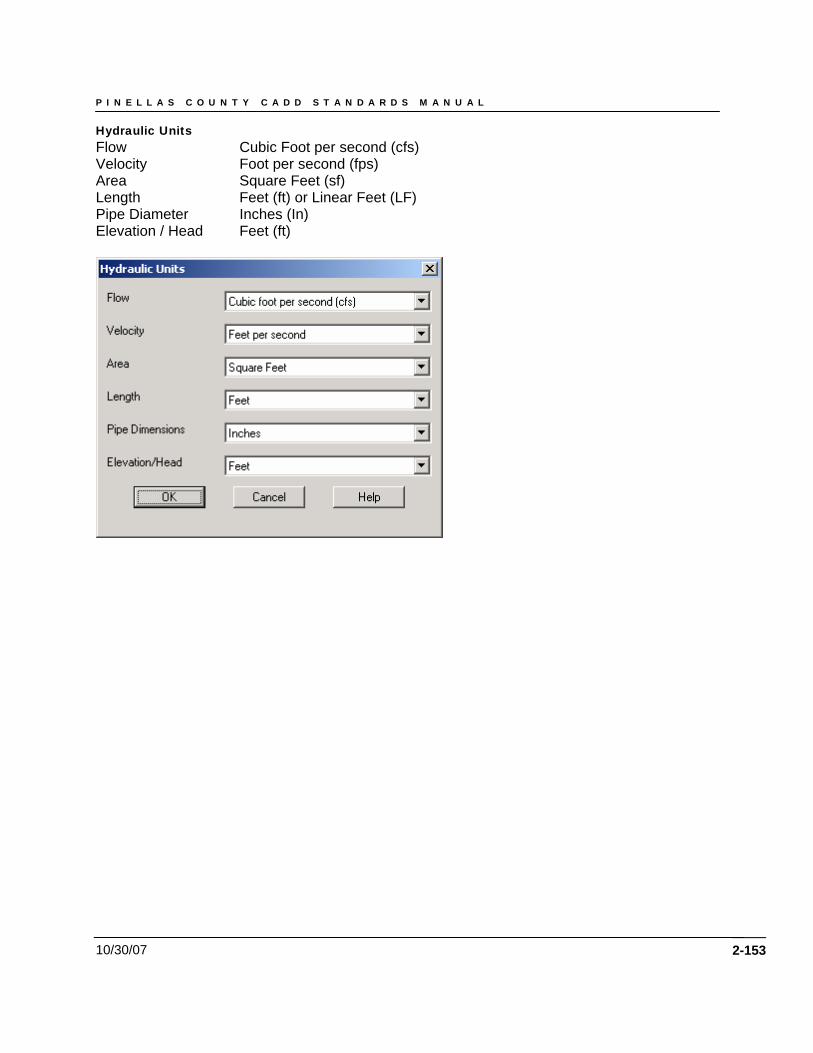
P I N E L L A S C O U N T Y C A D D S T A N D A R D S M A N U A L
10/30/07
Hydraulic Units Flow Cubic Foot per second (cfs) Velocity Foot per second (fps) Area Square Feet (sf) Length Feet (ft) or Linear Feet (LF) Pipe Diameter Inches (In) Elevation / Head Feet (ft)
2-153
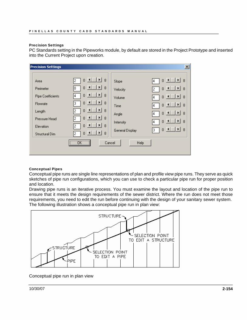
P I N E L L A S C O U N T Y C A D D S T A N D A R D S M A N U A L
10/30/07
Precision Settings PC Standards setting in the Pipeworks module, by default are stored in the Project Prototype and inserted into the Current Project upon creation.
Conceptual Pipes Conceptual pipe runs are single line representations of plan and profile view pipe runs. They serve as quick sketches of pipe run configurations, which you can use to check a particular pipe run for proper position and location. Drawing pipe runs is an iterative process. You must examine the layout and location of the pipe run to ensure that it meets the design requirements of the sewer district. Where the run does not meet those requirements, you need to edit the run before continuing with the design of your sanitary sewer system. The following illustration shows a conceptual pipe run in plan view:
Conceptual pipe run in plan view
2-154
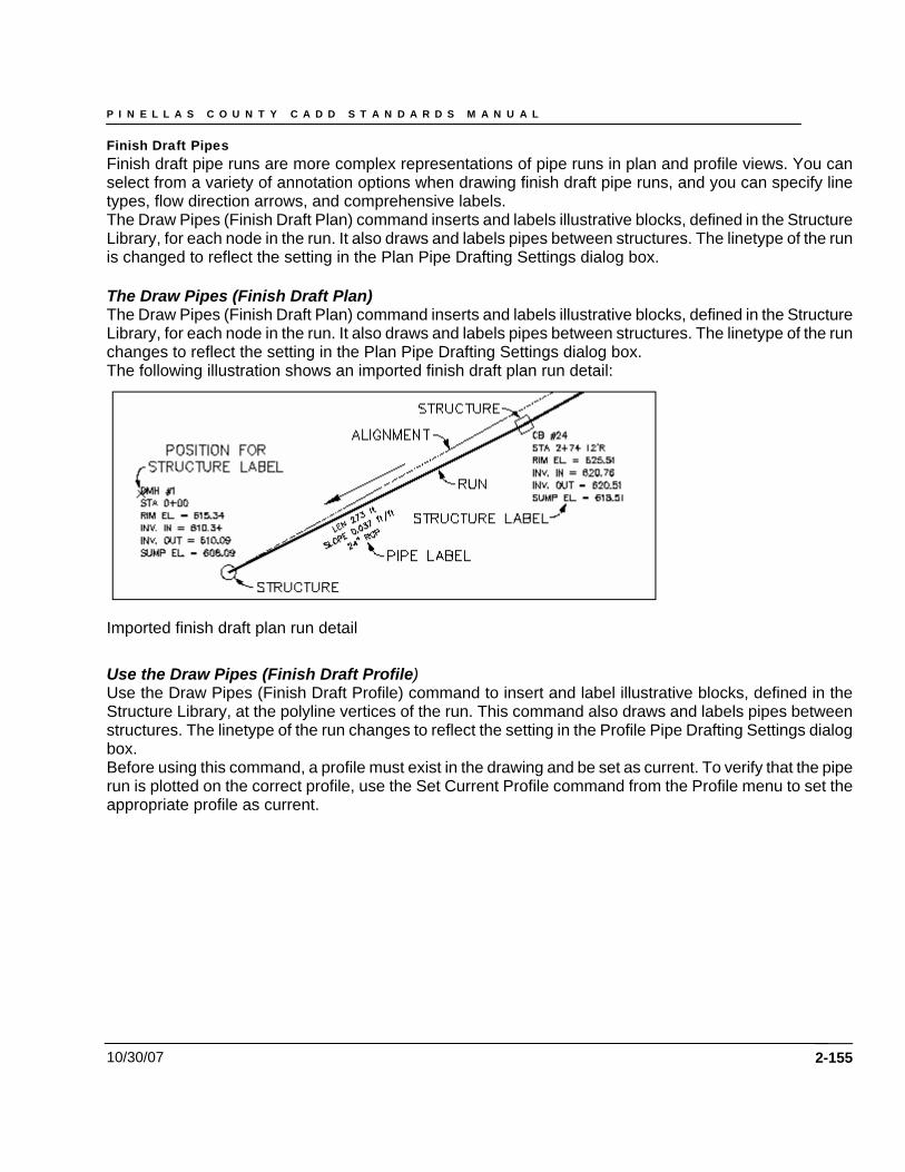
P I N E L L A S C O U N T Y C A D D S T A N D A R D S M A N U A L
10/30/07
Finish Draft Pipes Finish draft pipe runs are more complex representations of pipe runs in plan and profile views. You can select from a variety of annotation options when drawing finish draft pipe runs, and you can specify line types, flow direction arrows, and comprehensive labels. The Draw Pipes (Finish Draft Plan) command inserts and labels illustrative blocks, defined in the Structure Library, for each node in the run. It also draws and labels pipes between structures. The linetype of the run is changed to reflect the setting in the Plan Pipe Drafting Settings dialog box. The Draw Pipes (Finish Draft Plan) The Draw Pipes (Finish Draft Plan) command inserts and labels illustrative blocks, defined in the Structure Library, for each node in the run. It also draws and labels pipes between structures. The linetype of the run changes to reflect the setting in the Plan Pipe Drafting Settings dialog box. The following illustration shows an imported finish draft plan run detail:
Imported finish draft plan run detail Use the Draw Pipes (Finish Draft Profile) Use the Draw Pipes (Finish Draft Profile) command to insert and label illustrative blocks, defined in the Structure Library, at the polyline vertices of the run. This command also draws and labels pipes between structures. The linetype of the run changes to reflect the setting in the Profile Pipe Drafting Settings dialog box. Before using this command, a profile must exist in the drawing and be set as current. To verify that the pipe run is plotted on the correct profile, use the Set Current Profile command from the Profile menu to set the appropriate profile as current.
2-155
P I N E L L A S C O U N T Y C A D D S T A N D A R D S M A N U A L
10/30/07 2-156
Cross Sections Template Definition and Overview A template is a typical section of the finished design elements such as asphalt, concrete, and granular materials. Templates are made up of two basic elements: normal surfaces and subgrade surfaces. Normal surfaces are the elements of the template that make up the main part of the template such as pavement surfaces, median islands, shoulders and curbs. Subgrade surfaces are linked to the normal surfaces, but use separate design parameters to control the grade and depth of the surface. A typical subgrade surface is made up of granular substances such as gravel. All templates have a defined finished ground reference point which is used by the Edit Design Control command to position the template on the cross section using the horizontal alignment and the finished ground vertical alignment (the FGC profile) for control. This reference point is usually the crown of the roadway. After drawing the template, use the Define Template command to define it. You see different prompts when you use this command, depending on whether the template you are defining is composed of normal or subgrade surfaces. When defining a template with only normal surfaces, you are required to specify a finished ground reference point, a datum line, and connection-points-out. There is also an option to add subassemblies to the template definition. If you are defining a template with a subgrade surface, then you are not prompted to define the connection points, a datum line, or to attach subassemblies. The connection points are defined automatically at the outer end of the drawn portion of the subgrade and the datum lines are automatically generated along the bottom of each subgrade. Each datum line is numbered in ascending order, starting from the lowest subgrade on the template. Before defining templates, be sure to do the following tasks:
• Set the template storage path with the Set Template Path command. For more information, see “Setting the Path for Templates and Subassemblies” in the Land Desktop Help file.
• Draw the template surfaces as 2D polylines, either with the Draw Template command or the AutoCAD PLINE command. For more information, see “Drawing Templates”.
• For templates made up of Normal surfaces only, define any subassemblies to be attached. Subassemblies must be drawn as if they were being attached to the left side of the template. For more information, see “Defining Subassemblies” or “Drawing Subassemblies”.
NOTE: Subassemblies cannot be used on templates with subgrades. If subgrades are defined for a template, then you will not be prompted to attach subassemblies PC Standard Roadway Template Folder Setting your Template path to the Working Project Directory “RDtplates” folder Before creating templates or subassemblies, you need to set the location where they are stored by setting the template path. The template path is a project-based setting so that all drawings that are associated with a project use the same path. Template Path The master file for all templates supported by PC will be store on the network drive in the following path:
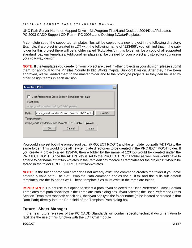
P I N E L L A S C O U N T Y C A D D S T A N D A R D S M A N U A L
10/30/07
UNC Path Server Name or Mapped Drive = M:\Program Files\Land Desktop 2004\Data\Rdtplates PC 2003 CADD Support CD-Rom = PC 2003\Land Desktop 3\Data\Rdtplates A complete set of the supported templates files will be copied to a new project in the following directory. Example: if a project is created in LDT with the following name of “123456”, you will find that in the sub-folder for this project there will be a folder called “Rdtplates”, in this folder will be a copy of all supported standard roadway templates. Additional templates can be created for your project and stored for your use in your roadway design. NOTE: If the templates you create for your project are used in other projects in your division, please submit them for approval to the Pinellas County Public Works Capital Support Division. After they have been approved, we will added them to the master folder and to the prototype projects so they can be used by other design teams in each division
You could also set both the project root path (PROJECT ROOT) and the template root path (ADTPL) to the same folder. This would force all new template directories to be created in the PROJECT ROOT folder. If you create a project called 123456, then a folder by the name of 123456 would be created under the PROJECT ROOT. Since the ADTPL key is set to the PROJECT ROOT folder as well, you would have to enter a folder name of 123456\tplates in the Path edit box to force all templates for the project 123456 to be stored in the folder PROJECT ROOT\123456\tplates. NOTE: If the folder name you enter does not already exist, the command creates the folder if you have entered a valid path. The Set Template Path command copies the nullt.tpl and the nulls.sub default templates into the folder as well. These template files must exist in the template folder. IMPORTANT: Do not use this option to select a path if you selected the User Preference Cross Section Templates root path check box in the Template Path dialog box. If you selected the User Preference Cross Section Templates root path check box, then you can type the folder name (to be located or created in that Root Path) directly into the Path field of the Template Path dialog box Future - Sheet Manager In the near future releases of the PC CADD Standards will contain specific technical documentation to facilitate the use of this function with the LDT Civil module
2-157
P I N E L L A S C O U N T Y C A D D S T A N D A R D S M A N U A L
10/30/07 2-158
Future - Import/Export of LandXML In the near future releases of the PC CADD Standards will contain specific technical documentation to facilitate the use of Importing and Exporting of LandXML data from within Land Desktop. Integrated LandXML Import/Export
• You will be able to use the Import LandXML and Export LandXML commands to import and export Autodesk Land Desktop project data in LandXML format. This feature was previously provided as an extension to AutoCAD Land Development Desktop 2i.
PC will also incorporate support for CADD technicians and Engineers to use the LandXML Import and Export commands to export and import point, surface, alignment, pipe data and parcel data in LandXML format. Also provided will be future support for Autodesk® Land Desktop 3 users who import XML files from Bentley Systems InRoads® software, due in late Oct-Nov. 2002 By transforming project data to LandXML, you can
• Exchange data: For example, you can import LandXML data into other software applications that support imported XML. The data can then be modified and delivered to customers and agencies in the required formats.
• Transfer/archive data: For example, you can transfer data to another Autodesk Land Desktop project, or archive project data in a non-proprietary format.
• Convert units: For example, you can export data from an imperial project, and then import it into a metric project to scale and convert values.
• Translate/rotate coordinates: For example, you can use these commands to globally adjust the elevations of project data.
• Identify project data that has changed: For example, if you change a project after exporting it, you can use the LandXML Import command (without actually importing data) to compare the current project with the exported LandXML file. Any differences between the project data are listed in the LandXML Import Comparison Results dialog box.
• Create custom reports: For example, you can transform the data into custom reports by applying XSL stylesheets. LandXML data is well suited for report generation and inquiry using web-friendly HTML and style sheet formatting. A variety of sample and customer-provided reporting tools are available for download via Point A at http://pointa.autodesk.com/gotoPointA.jsp?dest=LandXMLSheet. You can use this web site to download any stylesheet and customize it to meet your needs and you can upload any style sheet that you’d like to share with other professionals in the industry.
The LandXML Import and Export commands, located on the Projects menu, are based on the LandXML schema. For more information about the LandXML schema, go to www.landxml.org. PC will fully support the most current version available from the www.landxml.org. site and/or supported schemes provided by Autodesk, Inc. which support the current version of LDT.

P I N E L L A S C O U N T Y C A D D S T A N D A R D S M A N U A L
10/30/07 2-159
P I N E L L A S C O U N T Y C A D D S T A N D A R D S M A N U A L
10/30/07 2-160
Chapter 8
CADD Quality Assurance / Quality Control
P I N E L L A S C O U N T Y C A D D S T A N D A R D S M A N U A L
10/30/07 2-161
Chapter 6 - CADD Quality Assurance / Quality Control Pinellas County Civil Engineering Standards Conformance Divisions of Pinellas County are responsible to determine the critical Quality Assurance requirements for their functional areas and have developed plans to monitor those requirements. The Engineering / CADD Systems Office has defined the critical Quality requirements for electronic deliverables in the PC CADD Project Administration Manual. These include standard file formats and components for data delivery, adherence to a standard project directory structure, file naming conventions and standard graphic symbology for electronic plans as defined within this document. Capital Support Division office has established a QA monitoring program for CADD in PC to help facilitate compliance with these electronic deliverable requirements. In order to ensure adherence to the established AutoCAD standards for Pinellas County Civil Engineering projects, it will be necessary to obtain the Autodesk Standards Monitoring Extension software. This software is intended to check a design file’s adherence to the established standards within the PCEng STANDARDS.dws and PCSurvSTANDARDS.dws standards files and is available as part of the Autodesk PointA subscription program. Pinellas County does not maintain nor grant access to this application as part of the CADD Standards or associated Civil Engineering Standards documentation. Each design file shall meet the threshold of compliance as defined in the producers’ approved CADD quality control plan, or have a written variance from the PC project manager and documentation included in the project Journal. This report file is a critical indicator of the quality of the data found in the AutoCAD design files, which will affect downstream use of the data and archiving processes. The compliance report also documents whether or not the proper procedures and standards are being met, and shall be submitted as part of the electronic deliverables. Autodesk Standards Monitoring Extension The software can be initiated from both within Land Desktop as well as from the Autodesk Programs group in the Start menu, and may be run as a batch process against several drawing files as specified by the user. The Autodesk Standards Monitoring Extension will check the requested file(s) against the Pinellas County Civil Engineering Standards for the correct Layer, Linetype, Dimension Styles, and Text Styles and record their compliance status within a standard XML (Extended Markup Language) report with the same name as the drawing files being checked. This report is viewable from within the Batch Standards Checker and will be saved to the project directory as prompted to do so upon report generation.
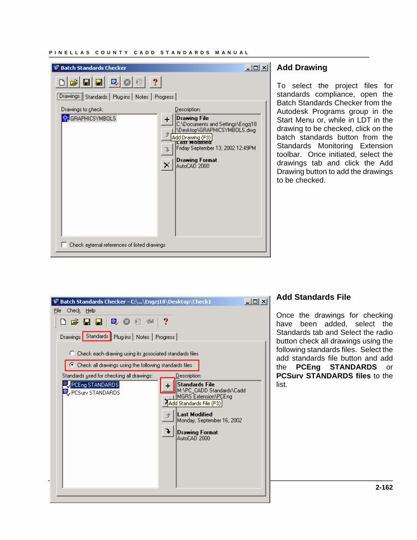
P I N E L L A S C O U N T Y C A D D S T A N D A R D S M A N U A L
Add Drawing To select the project files for standards compliance, open the Batch Standards Checker from the Autodesk Programs group in the Start Menu or, while in LDT in the drawing to be checked, click on the batch standards button from the Standards Monitoring Extension toolbar. Once initiated, select the drawings tab and click the Add Drawing button to add the drawings to be checked.
Add Standards File
10/30/07
Once the drawings for checking have been added, select the Standards tab and Select the radio button check all drawings using the following standards files. Select the add standards file button and add the PCEng STANDARDS or PCSurv STANDARDS files to the list.
2-162
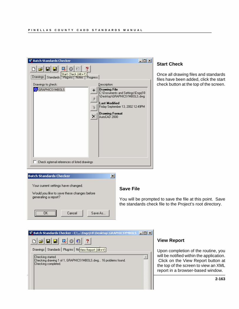
P I N E L L A S C O U N T Y C A D D S T A N D A R D S M A N U A L
Start Check Once all drawing files and standards files have been added, click the start check button at the top of the screen.
Save File You will be prompted to save the file at this point. Save the standards check file to the Project’s root directory.
10/30/07
View Report Upon completion of the routine, you will be notified within the application. Click on the View Report button at the top of the screen to view an XML report in a browser-based window.
2-163
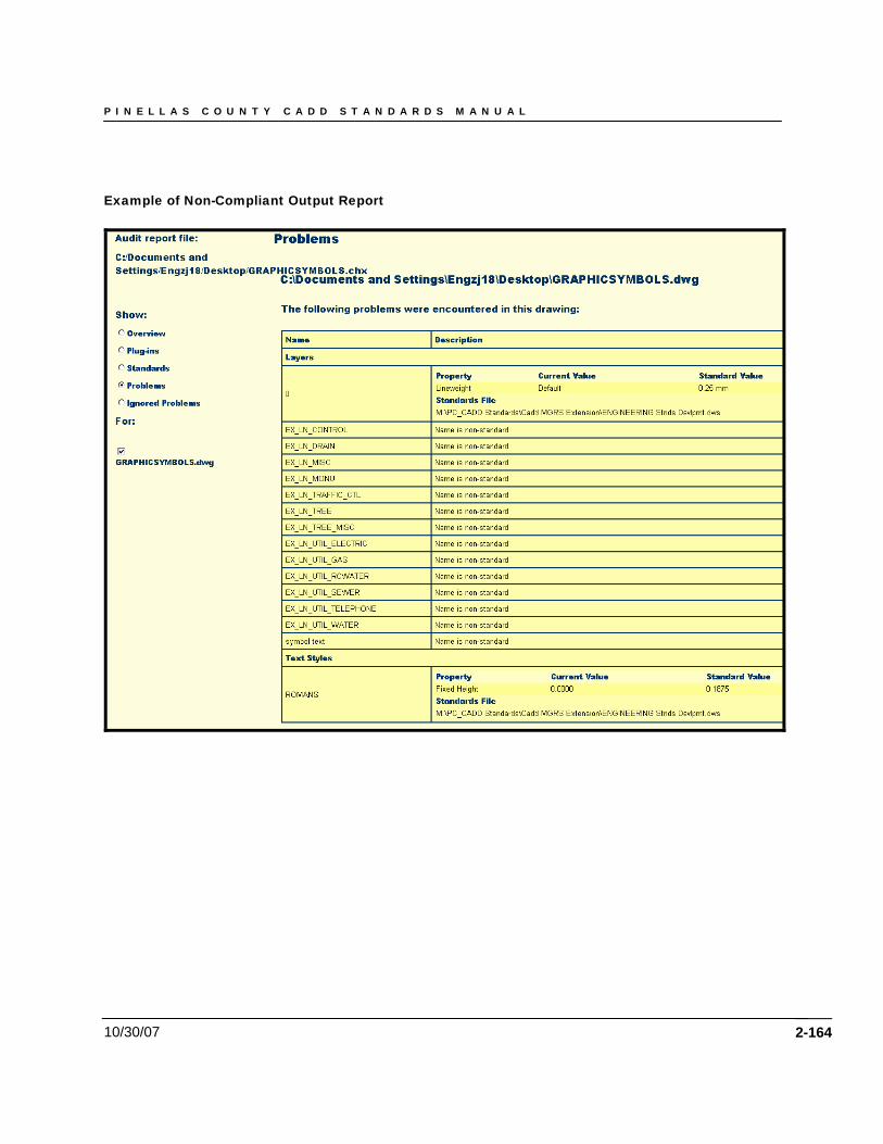
P I N E L L A S C O U N T Y C A D D S T A N D A R D S M A N U A L
10/30/07
Example of Non-Compliant Output Report
2-164
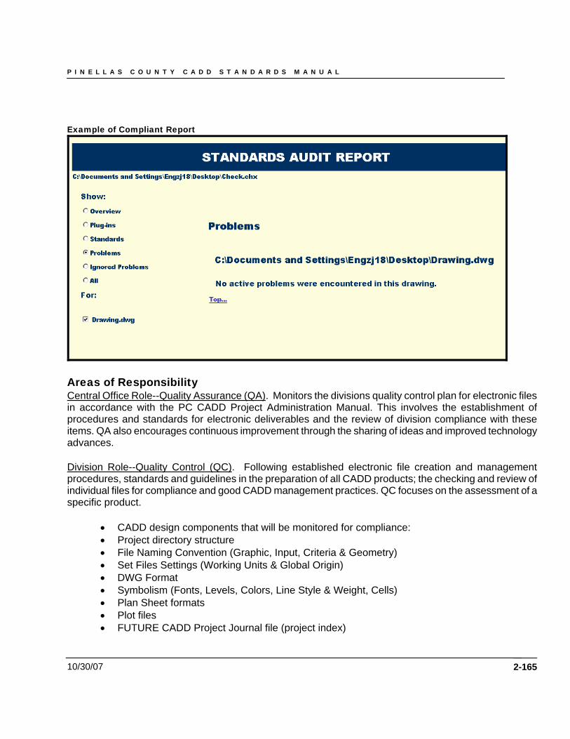
P I N E L L A S C O U N T Y C A D D S T A N D A R D S M A N U A L
10/30/07
Example of Compliant Report
Areas of Responsibility Central Office Role--Quality Assurance (QA). Monitors the divisions quality control plan for electronic files in accordance with the PC CADD Project Administration Manual. This involves the establishment of procedures and standards for electronic deliverables and the review of division compliance with these items. QA also encourages continuous improvement through the sharing of ideas and improved technology advances. Division Role--Quality Control (QC). Following established electronic file creation and management procedures, standards and guidelines in the preparation of all CADD products; the checking and review of individual files for compliance and good CADD management practices. QC focuses on the assessment of a specific product.
• CADD design components that will be monitored for compliance: • Project directory structure • File Naming Convention (Graphic, Input, Criteria & Geometry) • Set Files Settings (Working Units & Global Origin) • DWG Format • Symbolism (Fonts, Levels, Colors, Line Style & Weight, Cells) • Plan Sheet formats • Plot files • FUTURE CADD Project Journal file (project index)
2-165
P I N E L L A S C O U N T Y C A D D S T A N D A R D S M A N U A L
10/30/07 2-166
Chapter 7
Project Journal Files
P I N E L L A S C O U N T Y C A D D S T A N D A R D S M A N U A L
10/30/07 2-167
Chapter 7 - Future Project Journal Files Future - Project Journal Guidelines A Project Journal (with a file Index included) will be produced and delivered in accordance with the PC CADD Project Administration Manual. The purpose for this journal is to aid downstream customers of the CADD data so they may utilize existing CADD work in their processes. The format of the journal will be an electronic file that will be included with the project data on the prescribed media. The journal will contain the following information:
• A listing (Index) of the files delivered, including brief descriptions of each file in the directory structure and where the file is located.
• Documentation about the data (metadata) including major processes used, special CADD decisions made, exceptions to standards that were made, problems encountered and work around, or other important issues that arose during the course of the CADD work. For example, if a custom line style needed to be created, the format, coding, layer association and files where that line style was used would be documented in the Journal. Other documentation such as the design software used, particular software settings, and other information that would help a downstream user of the data understand where and how the data was created should be documented.
PC has not established a specific format for the Journal / Index. However, the Department has provided an interim tool on the PC 2003 CADD CD to help produce an index. In the future, PC will supply a more complete tool to assist the CADD user with Journaling / Indexing activities. PC also allows 3rd party tools that will help produce the Journal, provided the resulting file(s) for the Journal can be viewed/printed with tools on-hand, such as those found in the Microsoft Office® Suite or an internet browser. The interim index tool currently provided by PC has the following properties:
• It produces the index in HTML format (viewable by a internet browser) that includes an overall project description and file listing in the project root directory with links to discipline specific HTML index files located in each sub-directory.
• The discipline HTML index files (in each project sub-directory) contain an index listing of all the electronic files for that sub-directory and their sub-directories with their accompanying descriptions (in associated HTML files). In these sub-indexes, a user can document the creation and purpose of critical files with a text editor, HTML editor, etc.
Important data that should also be contained in the Journal include:
• All information necessary for the regeneration or use of those files by subsequent customers of the CADD data
• Document the geometry database, controlling alignment and profile names and geometry input/output files, relevant survey information, cross sections and the methodology used to obtain the final geometric controls in the CADD product.
The project journal must be kept up to date as the CADD design work progresses and delivered with the project on the CD for archival purposes.
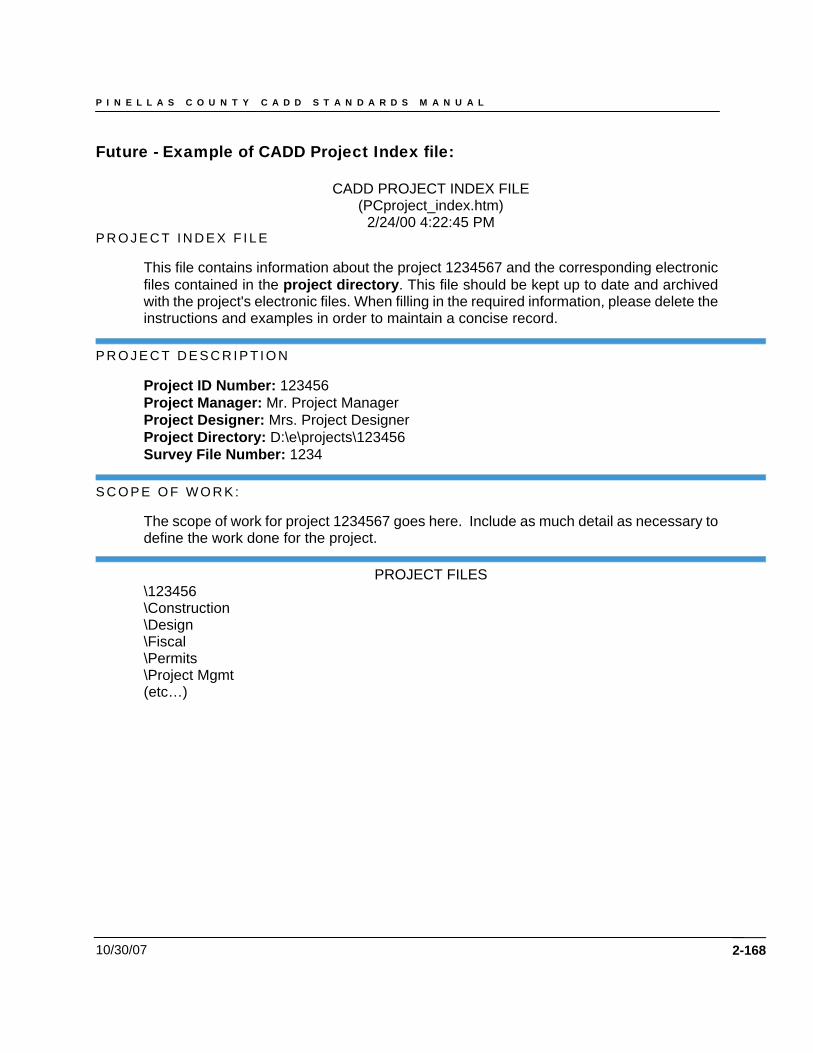
P I N E L L A S C O U N T Y C A D D S T A N D A R D S M A N U A L
10/30/07
Future - Example of CADD Project Index file:
CADD PROJECT INDEX FILE (PCproject_index.htm)
2/24/00 4:22:45 PM P R O J E C T I N D E X F I L E
This file contains information about the project 1234567 and the corresponding electronic files contained in the project directory. This file should be kept up to date and archived with the project's electronic files. When filling in the required information, please delete the instructions and examples in order to maintain a concise record.
P R O J E C T D E S C R I P T I O N
Project ID Number: 123456 Project Manager: Mr. Project Manager Project Designer: Mrs. Project Designer Project Directory: D:\e\projects\123456 Survey File Number: 1234
S C O P E O F W O R K :
The scope of work for project 1234567 goes here. Include as much detail as necessary to define the work done for the project.
PROJECT FILES \123456 \Construction \Design \Fiscal \Permits \Project Mgmt (etc…)
2-168
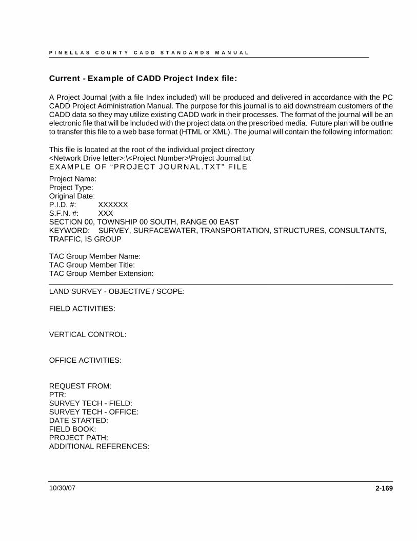
P I N E L L A S C O U N T Y C A D D S T A N D A R D S M A N U A L
10/30/07 2-169
Current - Example of CADD Project Index file: A Project Journal (with a file Index included) will be produced and delivered in accordance with the PC CADD Project Administration Manual. The purpose for this journal is to aid downstream customers of the CADD data so they may utilize existing CADD work in their processes. The format of the journal will be an electronic file that will be included with the project data on the prescribed media. Future plan will be outline to transfer this file to a web base format (HTML or XML). The journal will contain the following information: This file is located at the root of the individual project directory <Network Drive letter>:\<Project Number>\Project Journal.txt EXAMPLE OF “PROJECT JOURNAL .TXT” F ILE Project Name: Project Type: Original Date: P.I.D. #: XXXXXX S.F.N. #: XXX SECTION 00, TOWNSHIP 00 SOUTH, RANGE 00 EAST KEYWORD: SURVEY, SURFACEWATER, TRANSPORTATION, STRUCTURES, CONSULTANTS, TRAFFIC, IS GROUP TAC Group Member Name: TAC Group Member Title: TAC Group Member Extension: ____________________________________________________________________________________ LAND SURVEY - OBJECTIVE / SCOPE: FIELD ACTIVITIES: VERTICAL CONTROL: OFFICE ACTIVITIES: REQUEST FROM: PTR: SURVEY TECH - FIELD: SURVEY TECH - OFFICE: DATE STARTED: FIELD BOOK: PROJECT PATH: ADDITIONAL REFERENCES:
P I N E L L A S C O U N T Y C A D D S T A N D A R D S M A N U A L
10/30/07 2-170
DAILY AND/OR EVENT LOG FORMAT: DATE: 00/00/07 / USER NAME: __________________________________________________________________________________ ENGINEERING DESIGN - OBJECTIVE / SCOPE: OFFICE ACTIVITIES: REQUEST FROM: PTR: CADD TECH - OFFICE: PROJECT MANAGER: Division ENGINEER: DATE STARTED: PROJECT PATH: DRAWING REFERENCE: ADDITIONAL REFERENCES: DAILY AND/OR EVENT LOG FORMAT: DATE: 00/00/07 / USER NAME: ________________________________________________________________________________________________

P I N E L L A S C O U N T Y C A D D S T A N D A R D S M A N U A L
10/30/07 2-171
Chapter 8
Project Packaging for Electronic Submittal
P I N E L L A S C O U N T Y C A D D S T A N D A R D S M A N U A L
10/30/07 2-172
Chapter 8 - Future Project Packaging for Electronic Submittal Purpose The information in this Chapter sets standards for the exchange of electronic data within PC and for the submission of electronic data by consultants. This information is updated periodically as the technology changes. Consultants submitting electronic data to PC are responsible for ensuring that current versions of all standards are being used. File Formats and Standards
• Survey data shall be delivered in prescribed format in accordance with the PC CADD Project Administration Manual.
• All graphic files are to follow the naming and level conventions previously defined herein and shall be in AutoCAD .DWG format.
• All information shown on hard copies will be reflected in the CADD files. Pen changes to the hard copies are not allowed.
• Revisions done after the final design submittal will be made in the original files, not the clipped plan sheets or cross section sheet layout files, and resubmitted to the Project Manager. (By properly utilizing AutoCAD’s referencing capabilities the change only has to be made in one place)
• The PC standard sheet borders and fonts will be used for all sheets. The sheets and fonts are available in the PCEng and PCSurv standard LDT prototype projects.
• Final paper plots will be created from AutoCAD drawing (.dwg) files. Current PC Standard Software Versions: AutoCAD 2002 or greater Land Desktop Civil Design Survey Raster Design PC2000 Software Windows 2000, Service Pack 3 Internet Explorer 5.5 or greater Microsoft Word 2000 Microsoft Excel 2000 Microsoft Access 2000 Project Components A complete plans package entails the work of several disciplines, multiple Engineers of Record and even different consulting firms. Due to this fact, during the actual process of designing a project, the project electronic files will normally reside on many different machines, possibly at different locations or firms. Prior to the final submittal of the electronic plans to PC, all of the files must be merged under the standard project directory as described previously in this document. When the files are merged, close attention must be given to file names to ensure that the correct versions of files are delivered. Each discipline and Engineer of Record is responsible for the documentation of their directory and the corresponding PEDDS signature
P I N E L L A S C O U N T Y C A D D S T A N D A R D S M A N U A L
10/30/07 2-173
files. See the diagram of the Complete Project Directory for the Delivery CD on page 4-69, of this handbook for a picture of an entire project packaged for delivery. Contents of the Complete Delivery Package
• PEDDS Manifest and Signature files(if electronically signed and sealed) and the reports (signed) from PEDDS
• Project Journal, including Index files • Discipline directories and files • Postscript Images of each sheet produced for the plan set • Engineering ASCII Data • AutoCAD Resource files that were created by the producer • Other files that were used or produced in the course of doing the survey, design, mapping and
CADD work Authentication of the Electronic Files The responsibility for providing complete and correct electronic data to the PC Project Manager rests solely with the submitting provider. After all of the electronic files have been packaged together, the entire package must be secured for delivery. PEDDS will be used to secure a project directory just prior to the data being written to CD. No changes may be made to the data after this process in PEDDS is run, otherwise the data will have to be re-secured with PEDDS. Media Requirements All electronic projects submitted to PC will be on CD-ROM (multiple CD’s are allowed). All Project CD’s must be labeled, as a minimum, with the required project identification information as shown below. CDs not labeled with this information cannot be accepted.
Project Identification Label: Financial ID Number of Project: Project Description (including County and road number(s)): Firm doing the work (if done with consultant services): Firm’s Contract number with PC PC and Consultant Project Manager: Creation Date: Contact Person: Disc (#) of (total #)
In addition, a printed index of the all files on the media shall accompany all submissions. Electronic Data Submittal Checklist All electronic data submittals are transmitted to the PC Project Manager. The following questions should be answered before submittal and readily available for review by the Project Manager.

P I N E L L A S C O U N T Y C A D D S T A N D A R D S M A N U A L
10/30/07 2-174
1. Has a project journal been created for all files contained on the CD and is it accessible in the root directory of the project?
2. Is the list of the software packages and versions used to create the files included in the journal?
3. Are all the native files generated by the software programs used to design the project included in the package?
4. Are all graphics files in AutoCAD DWG format and in compliance with the PC CADD Standards?
5. Does the submittal include the AutoCAD external referenced files (Xrefs) that have been used with the project?
6. Has the supplied QC program, “Standards Monitoring Extension” been run against all the design files? Are the Compliance Reports included on the CD?
7. Has the project’s corresponding Engineering, Microsoft Word, HTML or ASCII data supporting the design been generated and placed on the CD?
8. Have LDT Project Engineering data files been created and included for the alignments, profiles, and quantities?
9. Has LDT Project Engineering data files been created, and included for the design surfaces represented in the cross sections?
10. Are all raster images submitted in Raster Design supported file format?
11. Have PostScript plot files been created, and included for all sheets in the plan set?
12. Were all final paper plots created from these plot files?
13. If the project is an electronically submitted, are the files representing the engineering work, referenced by Chapter 19 of the PC Plans Processing Manual, signed and sealed with PEDDS?
14. Has the entire CD been secured with PEDDS?
15. Are hardcopy reports of the PEDDS documents included, printed and signed?
16. Has the final CD for submission been re-checked to make sure the data is readable and authenticated?
P I N E L L A S C O U N T Y C A D D S T A N D A R D S M A N U A L
10/30/07 2-175
Chapter 9
CADD Standard Layers
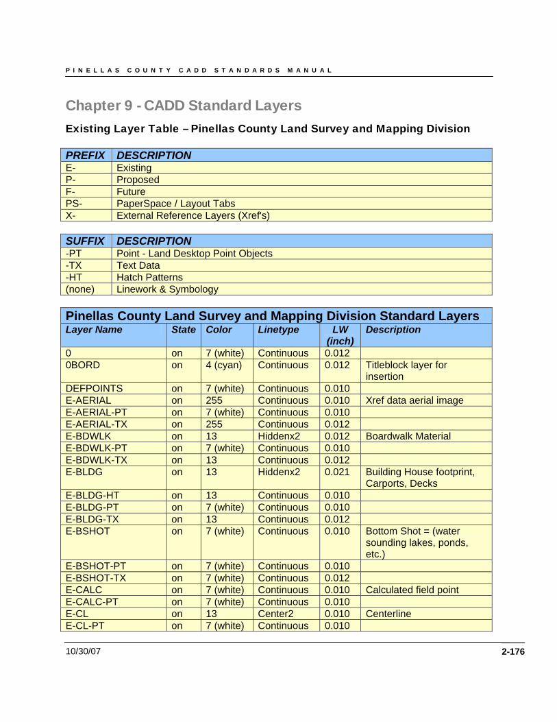
P I N E L L A S C O U N T Y C A D D S T A N D A R D S M A N U A L
10/30/07 2-176
Chapter 9 - CADD Standard Layers Existing Layer Table – Pinellas County Land Survey and Mapping Division PREFIX DESCRIPTION E- Existing P- Proposed F- Future PS- PaperSpace / Layout Tabs X- External Reference Layers (Xref's) SUFFIX DESCRIPTION -PT Point - Land Desktop Point Objects -TX Text Data -HT Hatch Patterns (none) Linework & Symbology Pinellas County Land Survey and Mapping Division Standard Layers Layer Name State Color Linetype LW
(inch) Description
0 on 7 (white) Continuous 0.012 0BORD on 4 (cyan) Continuous 0.012 Titleblock layer for
insertion DEFPOINTS on 7 (white) Continuous 0.010 E-AERIAL on 255 Continuous 0.010 Xref data aerial image E-AERIAL-PT on 7 (white) Continuous 0.010 E-AERIAL-TX on 255 Continuous 0.012 E-BDWLK on 13 Hiddenx2 0.012 Boardwalk Material E-BDWLK-PT on 7 (white) Continuous 0.010 E-BDWLK-TX on 13 Continuous 0.012 E-BLDG on 13 Hiddenx2 0.021 Building House footprint,
Carports, Decks E-BLDG-HT on 13 Continuous 0.010 E-BLDG-PT on 7 (white) Continuous 0.010 E-BLDG-TX on 13 Continuous 0.012 E-BSHOT on 7 (white) Continuous 0.010 Bottom Shot = (water
sounding lakes, ponds, etc.)
E-BSHOT-PT on 7 (white) Continuous 0.010 E-BSHOT-TX on 7 (white) Continuous 0.012 E-CALC on 7 (white) Continuous 0.010 Calculated field point E-CALC-PT on 7 (white) Continuous 0.010 E-CL on 13 Center2 0.010 Centerline E-CL-PT on 7 (white) Continuous 0.010
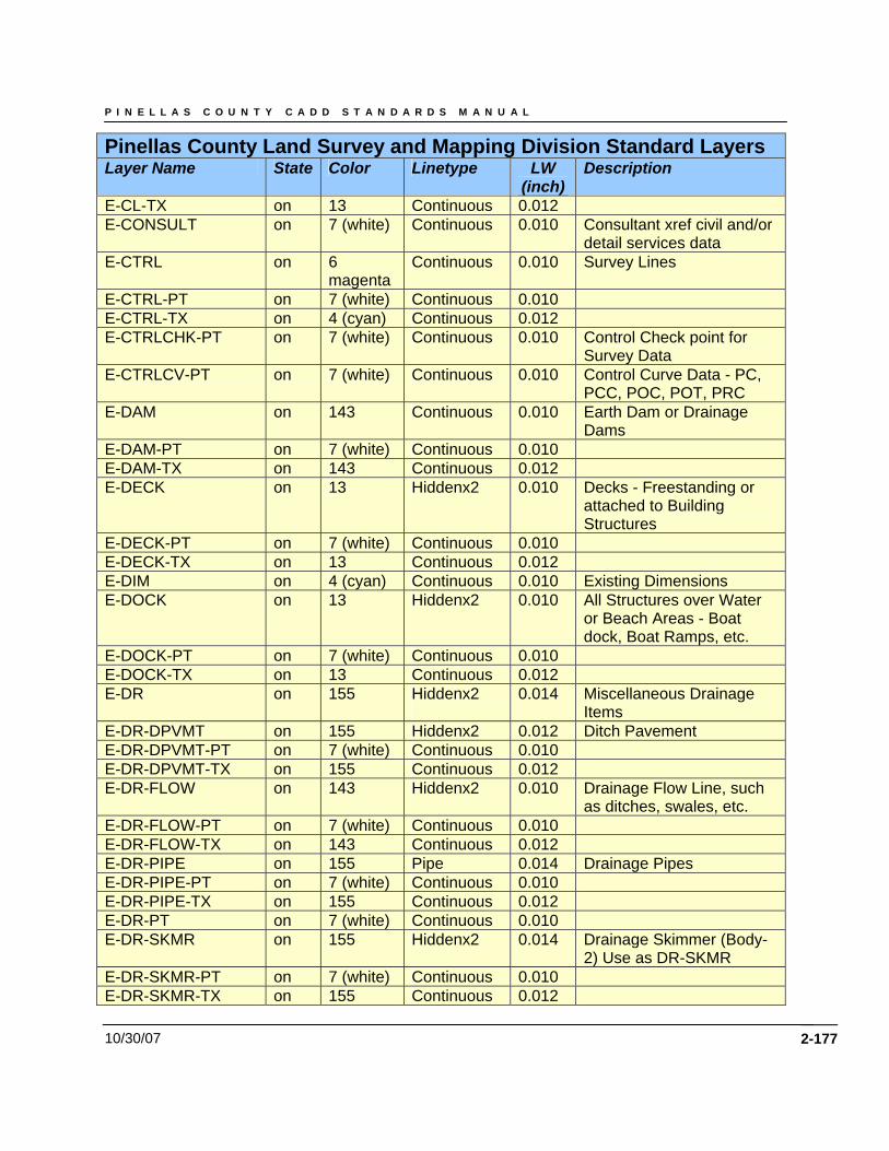
P I N E L L A S C O U N T Y C A D D S T A N D A R D S M A N U A L
10/30/07 2-177
Pinellas County Land Survey and Mapping Division Standard Layers Layer Name State Color Linetype LW
(inch) Description
E-CL-TX on 13 Continuous 0.012 E-CONSULT on 7 (white) Continuous 0.010 Consultant xref civil and/or
detail services data E-CTRL on 6
magenta Continuous 0.010 Survey Lines
E-CTRL-PT on 7 (white) Continuous 0.010 E-CTRL-TX on 4 (cyan) Continuous 0.012 E-CTRLCHK-PT on 7 (white) Continuous 0.010 Control Check point for
Survey Data E-CTRLCV-PT on 7 (white) Continuous 0.010 Control Curve Data - PC,
PCC, POC, POT, PRC E-DAM on 143 Continuous 0.010 Earth Dam or Drainage
Dams E-DAM-PT on 7 (white) Continuous 0.010 E-DAM-TX on 143 Continuous 0.012 E-DECK on 13 Hiddenx2 0.010 Decks - Freestanding or
attached to Building Structures
E-DECK-PT on 7 (white) Continuous 0.010 E-DECK-TX on 13 Continuous 0.012 E-DIM on 4 (cyan) Continuous 0.010 Existing Dimensions E-DOCK on 13 Hiddenx2 0.010 All Structures over Water
or Beach Areas - Boat dock, Boat Ramps, etc.
E-DOCK-PT on 7 (white) Continuous 0.010 E-DOCK-TX on 13 Continuous 0.012 E-DR on 155 Hiddenx2
0.014 Miscellaneous Drainage
Items E-DR-DPVMT on 155 Hiddenx2 0.012 Ditch Pavement E-DR-DPVMT-PT on 7 (white) Continuous 0.010 E-DR-DPVMT-TX on 155 Continuous 0.012 E-DR-FLOW on 143 Hiddenx2 0.010 Drainage Flow Line, such
as ditches, swales, etc. E-DR-FLOW-PT on 7 (white) Continuous 0.010 E-DR-FLOW-TX on 143 Continuous 0.012 E-DR-PIPE on 155 Pipe 0.014 Drainage Pipes E-DR-PIPE-PT on 7 (white) Continuous 0.010 E-DR-PIPE-TX on 155 Continuous 0.012 E-DR-PT on 7 (white) Continuous 0.010 E-DR-SKMR on 155 Hiddenx2 0.014 Drainage Skimmer (Body-
2) Use as DR-SKMR E-DR-SKMR-PT on 7 (white) Continuous 0.010 E-DR-SKMR-TX on 155 Continuous 0.012
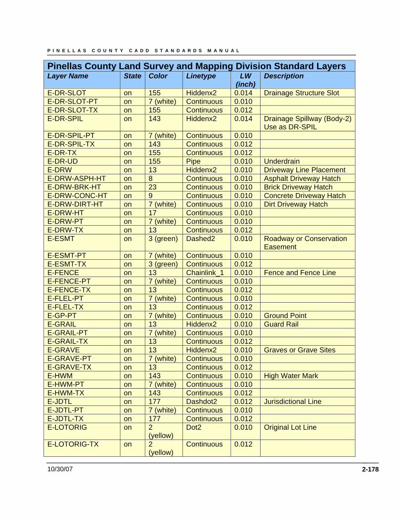
P I N E L L A S C O U N T Y C A D D S T A N D A R D S M A N U A L
10/30/07 2-178
Pinellas County Land Survey and Mapping Division Standard Layers Layer Name State Color Linetype LW
(inch) Description
E-DR-SLOT on 155 Hiddenx2 0.014 Drainage Structure Slot E-DR-SLOT-PT on 7 (white) Continuous 0.010 E-DR-SLOT-TX on 155 Continuous 0.012 E-DR-SPIL on 143 Hiddenx2 0.014 Drainage Spillway (Body-2)
Use as DR-SPIL E-DR-SPIL-PT on 7 (white) Continuous 0.010 E-DR-SPIL-TX on 143 Continuous 0.012 E-DR-TX on 155 Continuous 0.012 E-DR-UD on 155 Pipe 0.010 Underdrain E-DRW on 13 Hiddenx2 0.010 Driveway Line Placement E-DRW-ASPH-HT on 8 Continuous 0.010 Asphalt Driveway Hatch E-DRW-BRK-HT on 23 Continuous 0.010 Brick Driveway Hatch E-DRW-CONC-HT on 9 Continuous 0.010 Concrete Driveway Hatch E-DRW-DIRT-HT on 7 (white) Continuous 0.010 Dirt Driveway Hatch E-DRW-HT on 17 Continuous 0.010 E-DRW-PT on 7 (white) Continuous 0.010 E-DRW-TX on 13 Continuous 0.012 E-ESMT on 3 (green) Dashed2 0.010 Roadway or Conservation
Easement E-ESMT-PT on 7 (white) Continuous 0.010 E-ESMT-TX on 3 (green) Continuous 0.012 E-FENCE on 13 Chainlink_1 0.010 Fence and Fence Line E-FENCE-PT on 7 (white) Continuous 0.010 E-FENCE-TX on 13 Continuous 0.012 E-FLEL-PT on 7 (white) Continuous 0.010 E-FLEL-TX on 13 Continuous 0.012 E-GP-PT on 7 (white) Continuous 0.010 Ground Point E-GRAIL on 13 Hiddenx2 0.010 Guard Rail E-GRAIL-PT on 7 (white) Continuous 0.010 E-GRAIL-TX on 13 Continuous 0.012 E-GRAVE on 13 Hiddenx2 0.010 Graves or Grave Sites E-GRAVE-PT on 7 (white) Continuous 0.010 E-GRAVE-TX on 13 Continuous 0.012 E-HWM on 143 Continuous 0.010 High Water Mark E-HWM-PT on 7 (white) Continuous 0.010 E-HWM-TX on 143 Continuous 0.012 E-JDTL on 177 Dashdot2 0.012 Jurisdictional Line E-JDTL-PT on 7 (white) Continuous 0.010 E-JDTL-TX on 177 Continuous 0.012 E-LOTORIG on 2
(yellow) Dot2 0.010 Original Lot Line
E-LOTORIG-TX on 2 (yellow)
Continuous 0.012
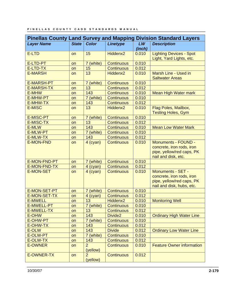
P I N E L L A S C O U N T Y C A D D S T A N D A R D S M A N U A L
10/30/07 2-179
Pinellas County Land Survey and Mapping Division Standard Layers Layer Name State Color Linetype LW
(inch) Description
E-LTD on 15 Hiddenx2 0.010 Lighting Devices - Spot Light, Yard Lights, etc.
E-LTD-PT on 7 (white) Continuous 0.010 E-LTD-TX on 15 Continuous 0.012 E-MARSH on 13 Hiddenx2 0.010 Marsh Line - Used in
Saltwater Areas E-MARSH-PT on 7 (white) Continuous 0.010 E-MARSH-TX on 13 Continuous 0.012 E-MHW on 143 Continuous 0.010 Mean High Water mark E-MHW-PT on 7 (white) Continuous 0.010 E-MHW-TX on 143 Continuous 0.012 E-MISC on 13 Hiddenx2 0.010 Flag Poles, Mailbox,
Testing Holes, Gym E-MISC-PT on 7 (white) Continuous 0.010 E-MISC-TX on 13 Continuous 0.012 E-MLW on 143 Continuous 0.010 Mean Low Water Mark E-MLW-PT on 7 (white) Continuous 0.010 E-MLW-TX on 143 Continuous 0.012 E-MON-FND on 4 (cyan) Continuous 0.010 Monuments - FOUND -
concrete, iron rods, iron pipe, yellow/red caps, PK nail and disk, etc.
E-MON-FND-PT on 7 (white) Continuous 0.010 E-MON-FND-TX on 4 (cyan) Continuous 0.012 E-MON-SET on 4 (cyan) Continuous 0.010 Monuments - SET -
concrete, iron rods, iron pipe, yellow/red caps, PK nail and disk, hubs, etc.
E-MON-SET-PT on 7 (white) Continuous 0.010 E-MON-SET-TX on 4 (cyan) Continuous 0.012 E-MWELL on 13 Hiddenx2 0.010 Monitoring Well E-MWELL-PT on 7 (white) Continuous 0.010 E-MWELL-TX on 13 Continuous 0.012 E-OHW on 143 Divide2 0.010 Ordinary High Water Line E-OHW-PT on 7 (white) Continuous 0.010 E-OHW-TX on 143 Continuous 0.012 E-OLW on 143 Divide 0.012 Ordinary Low Water Line E-OLW-PT on 7 (white) Continuous 0.010 E-OLW-TX on 143 Continuous 0.012 E-OWNER on 2
(yellow) Continuous 0.010 Feature Owner information
E-OWNER-TX on 2 (yellow)
Continuous 0.012
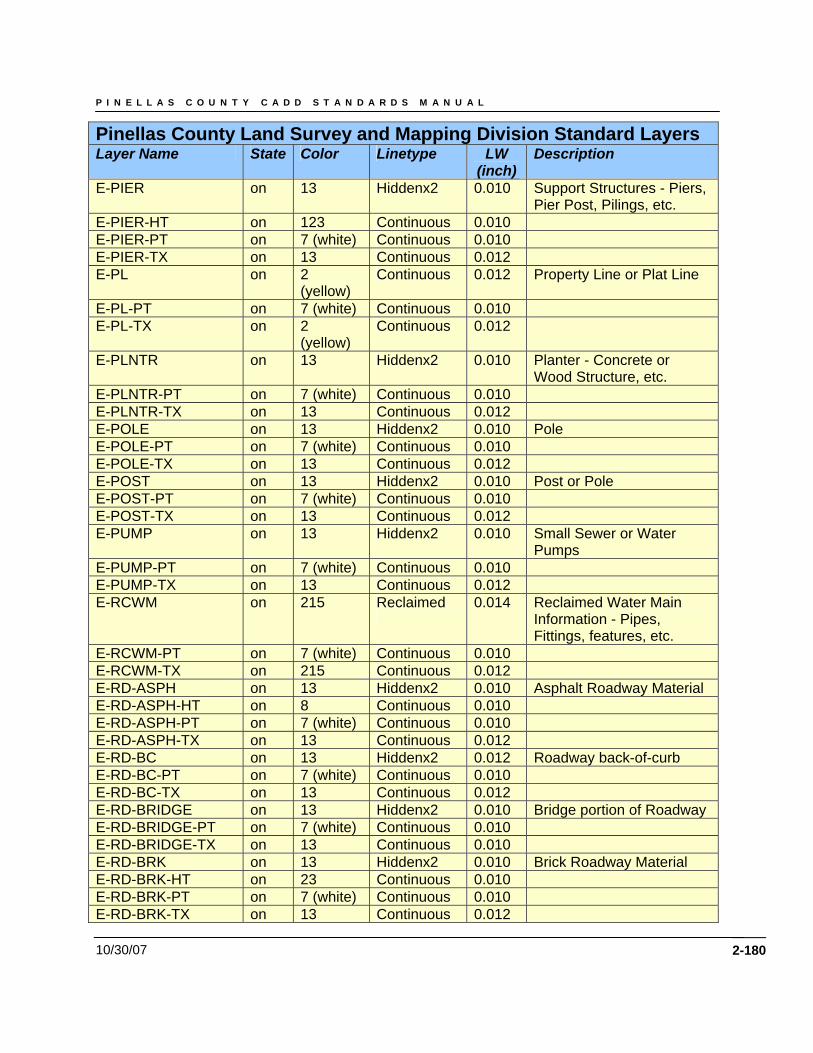
P I N E L L A S C O U N T Y C A D D S T A N D A R D S M A N U A L
10/30/07 2-180
Pinellas County Land Survey and Mapping Division Standard Layers Layer Name State Color Linetype LW
(inch) Description
E-PIER on 13 Hiddenx2 0.010 Support Structures - Piers, Pier Post, Pilings, etc.
E-PIER-HT on 123 Continuous 0.010 E-PIER-PT on 7 (white) Continuous 0.010 E-PIER-TX on 13 Continuous 0.012 E-PL on 2
(yellow) Continuous 0.012 Property Line or Plat Line
E-PL-PT on 7 (white) Continuous 0.010 E-PL-TX on 2
(yellow) Continuous 0.012
E-PLNTR on 13 Hiddenx2 0.010 Planter - Concrete or Wood Structure, etc.
E-PLNTR-PT on 7 (white) Continuous 0.010 E-PLNTR-TX on 13 Continuous 0.012 E-POLE on 13 Hiddenx2 0.010 Pole E-POLE-PT on 7 (white) Continuous 0.010 E-POLE-TX on 13 Continuous 0.012 E-POST on 13 Hiddenx2 0.010 Post or Pole E-POST-PT on 7 (white) Continuous 0.010 E-POST-TX on 13 Continuous 0.012 E-PUMP on 13 Hiddenx2 0.010 Small Sewer or Water
Pumps E-PUMP-PT on 7 (white) Continuous 0.010 E-PUMP-TX on 13 Continuous 0.012 E-RCWM on 215 Reclaimed
0.014 Reclaimed Water Main
Information - Pipes, Fittings, features, etc.
E-RCWM-PT on 7 (white) Continuous 0.010 E-RCWM-TX on 215 Continuous 0.012 E-RD-ASPH on 13 Hiddenx2 0.010 Asphalt Roadway Material E-RD-ASPH-HT on 8 Continuous 0.010 E-RD-ASPH-PT on 7 (white) Continuous 0.010 E-RD-ASPH-TX on 13 Continuous 0.012 E-RD-BC on 13 Hiddenx2 0.012 Roadway back-of-curb E-RD-BC-PT on 7 (white) Continuous 0.010 E-RD-BC-TX on 13 Continuous 0.012 E-RD-BRIDGE on 13 Hiddenx2 0.010 Bridge portion of Roadway E-RD-BRIDGE-PT on 7 (white) Continuous 0.010 E-RD-BRIDGE-TX on 13 Continuous 0.010 E-RD-BRK on 13 Hiddenx2 0.010 Brick Roadway Material E-RD-BRK-HT on 23 Continuous 0.010 E-RD-BRK-PT on 7 (white) Continuous 0.010 E-RD-BRK-TX on 13 Continuous 0.012
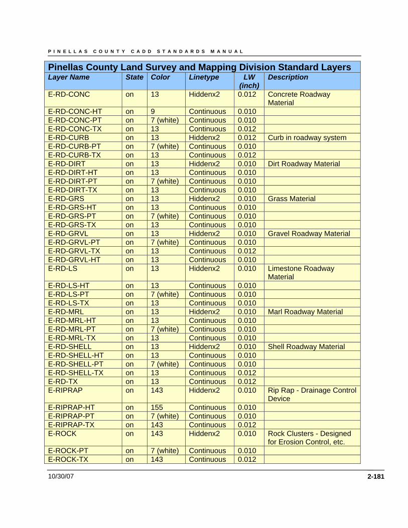
P I N E L L A S C O U N T Y C A D D S T A N D A R D S M A N U A L
10/30/07 2-181
Pinellas County Land Survey and Mapping Division Standard Layers Layer Name State Color Linetype LW
(inch) Description
E-RD-CONC on 13 Hiddenx2 0.012 Concrete Roadway Material
E-RD-CONC-HT on 9 Continuous 0.010 E-RD-CONC-PT on 7 (white) Continuous 0.010 E-RD-CONC-TX on 13 Continuous 0.012 E-RD-CURB on 13 Hiddenx2 0.012 Curb in roadway system E-RD-CURB-PT on 7 (white) Continuous 0.010 E-RD-CURB-TX on 13 Continuous 0.012 E-RD-DIRT on 13 Hiddenx2 0.010 Dirt Roadway Material E-RD-DIRT-HT on 13 Continuous 0.010 E-RD-DIRT-PT on 7 (white) Continuous 0.010 E-RD-DIRT-TX on 13 Continuous 0.010 E-RD-GRS on 13 Hiddenx2 0.010 Grass Material E-RD-GRS-HT on 13 Continuous 0.010 E-RD-GRS-PT on 7 (white) Continuous 0.010 E-RD-GRS-TX on 13 Continuous 0.010 E-RD-GRVL on 13 Hiddenx2 0.010 Gravel Roadway Material E-RD-GRVL-PT on 7 (white) Continuous 0.010 E-RD-GRVL-TX on 13 Continuous 0.012 E-RD-GRVL-HT on 13 Continuous 0.010 E-RD-LS on 13 Hiddenx2 0.010 Limestone Roadway
Material E-RD-LS-HT on 13 Continuous 0.010 E-RD-LS-PT on 7 (white) Continuous 0.010 E-RD-LS-TX on 13 Continuous 0.010 E-RD-MRL on 13 Hiddenx2 0.010 Marl Roadway Material E-RD-MRL-HT on 13 Continuous 0.010 E-RD-MRL-PT on 7 (white) Continuous 0.010 E-RD-MRL-TX on 13 Continuous 0.010 E-RD-SHELL on 13 Hiddenx2 0.010 Shell Roadway Material E-RD-SHELL-HT on 13 Continuous 0.010 E-RD-SHELL-PT on 7 (white) Continuous 0.010 E-RD-SHELL-TX on 13 Continuous 0.012 E-RD-TX on 13 Continuous 0.012 E-RIPRAP on 143 Hiddenx2 0.010 Rip Rap - Drainage Control
Device E-RIPRAP-HT on 155 Continuous 0.010 E-RIPRAP-PT on 7 (white) Continuous 0.010 E-RIPRAP-TX on 143 Continuous 0.012 E-ROCK on 143 Hiddenx2 0.010 Rock Clusters - Designed
for Erosion Control, etc. E-ROCK-PT on 7 (white) Continuous 0.010 E-ROCK-TX on 143 Continuous 0.012
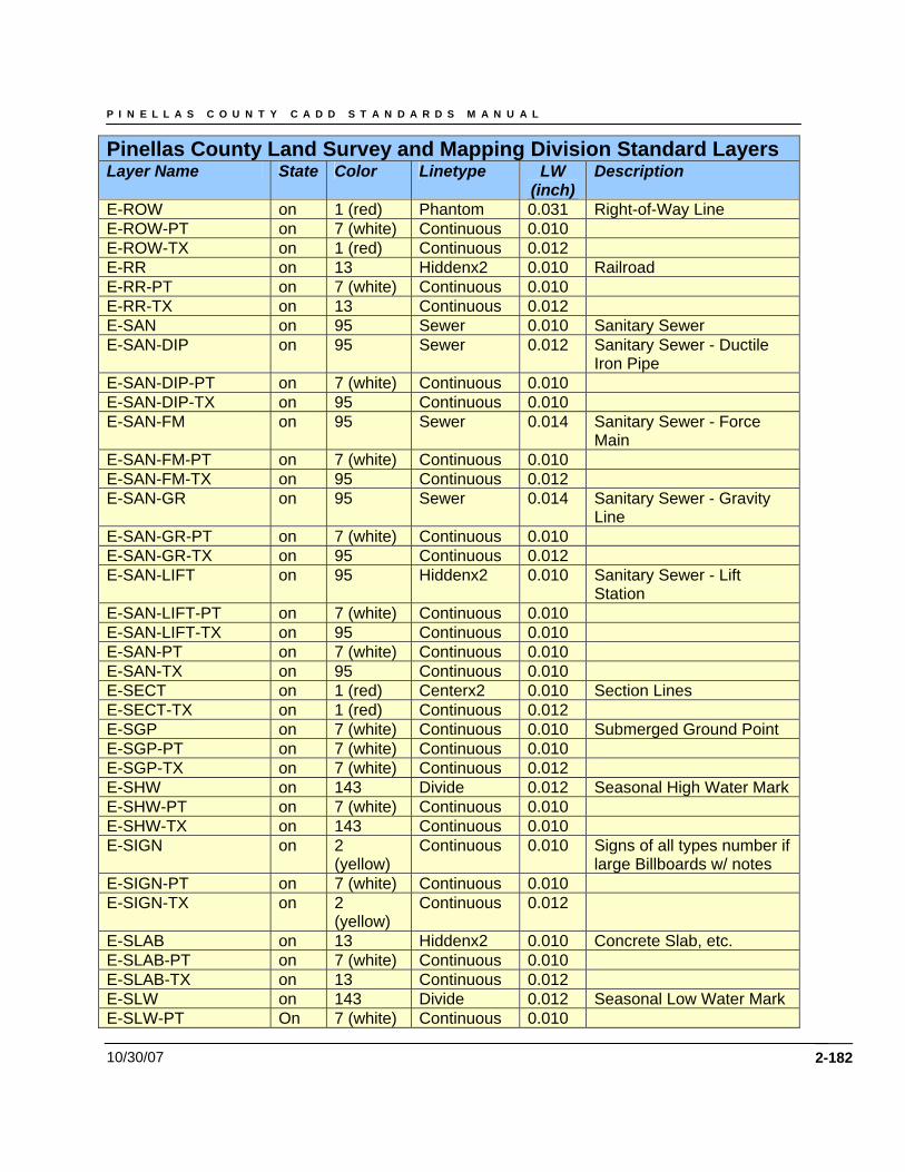
P I N E L L A S C O U N T Y C A D D S T A N D A R D S M A N U A L
10/30/07 2-182
Pinellas County Land Survey and Mapping Division Standard Layers Layer Name State Color Linetype LW
(inch) Description
E-ROW on 1 (red) Phantom 0.031 Right-of-Way Line E-ROW-PT on 7 (white) Continuous 0.010 E-ROW-TX on 1 (red) Continuous 0.012 E-RR on 13 Hiddenx2 0.010 Railroad E-RR-PT on 7 (white) Continuous 0.010 E-RR-TX on 13 Continuous 0.012 E-SAN on 95 Sewer 0.010 Sanitary Sewer E-SAN-DIP on 95 Sewer 0.012 Sanitary Sewer - Ductile
Iron Pipe E-SAN-DIP-PT on 7 (white) Continuous 0.010 E-SAN-DIP-TX on 95 Continuous 0.010 E-SAN-FM on 95 Sewer 0.014 Sanitary Sewer - Force
Main E-SAN-FM-PT on 7 (white) Continuous 0.010 E-SAN-FM-TX on 95 Continuous 0.012 E-SAN-GR on 95 Sewer 0.014 Sanitary Sewer - Gravity
Line E-SAN-GR-PT on 7 (white) Continuous 0.010 E-SAN-GR-TX on 95 Continuous 0.012 E-SAN-LIFT on 95 Hiddenx2 0.010 Sanitary Sewer - Lift
Station E-SAN-LIFT-PT on 7 (white) Continuous 0.010 E-SAN-LIFT-TX on 95 Continuous 0.010 E-SAN-PT on 7 (white) Continuous 0.010 E-SAN-TX on 95 Continuous 0.010 E-SECT on 1 (red) Centerx2 0.010 Section Lines E-SECT-TX on 1 (red) Continuous 0.012 E-SGP on 7 (white) Continuous 0.010 Submerged Ground Point E-SGP-PT on 7 (white) Continuous 0.010 E-SGP-TX on 7 (white) Continuous 0.012 E-SHW on 143 Divide 0.012 Seasonal High Water Mark E-SHW-PT on 7 (white) Continuous 0.010 E-SHW-TX on 143 Continuous 0.010 E-SIGN on 2
(yellow) Continuous 0.010 Signs of all types number if
large Billboards w/ notes E-SIGN-PT on 7 (white) Continuous 0.010 E-SIGN-TX on 2
(yellow) Continuous 0.012
E-SLAB on 13 Hiddenx2 0.010 Concrete Slab, etc. E-SLAB-PT on 7 (white) Continuous 0.010 E-SLAB-TX on 13 Continuous 0.012 E-SLW on 143 Divide 0.012 Seasonal Low Water Mark E-SLW-PT On 7 (white) Continuous 0.010
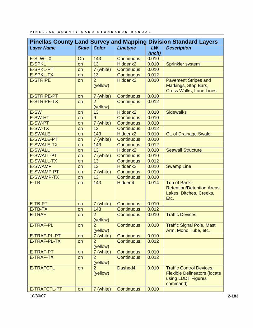
P I N E L L A S C O U N T Y C A D D S T A N D A R D S M A N U A L
10/30/07 2-183
Pinellas County Land Survey and Mapping Division Standard Layers Layer Name State Color Linetype LW
(inch) Description
E-SLW-TX On 143 Continuous 0.010 E-SPKL on 13 Hiddenx2 0.010 Sprinkler system E-SPKL-PT on 7 (white) Continuous 0.010 E-SPKL-TX on 13 Continuous 0.012 E-STRIPE on 2
(yellow) Hiddenx2 0.010 Pavement Stripes and
Markings, Stop Bars, Cross Walks, Lane Lines
E-STRIPE-PT on 7 (white) Continuous 0.010 E-STRIPE-TX on 2
(yellow) Continuous 0.012
E-SW on 13 Hiddenx2 0.010 Sidewalks E-SW-HT on 9 Continuous 0.010 E-SW-PT on 7 (white) Continuous 0.010 E-SW-TX on 13 Continuous 0.012 E-SWALE on 143 Hiddenx2 0.010 CL of Drainage Swale E-SWALE-PT on 7 (white) Continuous 0.010 E-SWALE-TX on 143 Continuous 0.012 E-SWALL on 13 Hiddenx2 0.010 Seawall Structure E-SWALL-PT on 7 (white) Continuous 0.010 E-SWALL-TX on 13 Continuous 0.012 E-SWAMP on 13 Hiddenx2 0.010 Swamp Line E-SWAMP-PT on 7 (white) Continuous 0.010 E-SWAMP-TX on 13 Continuous 0.010 E-TB on 143 Hidden4 0.014 Top of Bank -
Retention/Detention Areas, Lakes, Ditches, Creeks, Etc.
E-TB-PT on 7 (white) Continuous 0.010 E-TB-TX on 143 Continuous 0.012 E-TRAF on 2
(yellow) Continuous 0.010 Traffic Devices
E-TRAF-PL on 2 (yellow)
Continuous 0.010 Traffic Signal Pole, Mast Arm, Mono Tube, etc.
E-TRAF-PL-PT on 7 (white) Continuous 0.010 E-TRAF-PL-TX on 2
(yellow) Continuous 0.012
E-TRAF-PT on 7 (white) Continuous 0.010 E-TRAF-TX on 2
(yellow) Continuous 0.012
E-TRAFCTL on 2 (yellow)
Dashed4 0.010 Traffic Control Devices, Flexible Delineators (locate using LDDT Figures command)
E-TRAFCTL-PT on 7 (white) Continuous 0.010
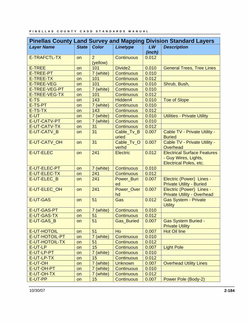
P I N E L L A S C O U N T Y C A D D S T A N D A R D S M A N U A L
10/30/07 2-184
Pinellas County Land Survey and Mapping Division Standard Layers Layer Name State Color Linetype LW
(inch) Description
E-TRAFCTL-TX on 2 (yellow)
Continuous 0.012
E-TREE on 101 Divide2 0.010 General Trees, Tree Lines E-TREE-PT on 7 (white) Continuous 0.010 E-TREE-TX on 101 Continuous 0.012 E-TREE-VEG on 101 Continuous 0.010 Shrub, Bush, E-TREE-VEG-PT on 7 (white) Continuous 0.010 E-TREE-VEG-TX on 101 Continuous 0.012 E-TS on 143 Hidden4 0.010 Toe of Slope E-TS-PT on 7 (white) Continuous 0.010 E-TS-TX on 143 Continuous 0.012 E-UT on 7 (white) Continuous 0.010 Utilities - Private Utility E-UT-CATV-PT on 7 (white) Continuous 0.010 E-UT-CATV-TX on 31 Continuous 0.012 E-UT-CATV_B on 31 Cable_Tv_B
uried 0.007 Cable TV - Private Utility -
Buried E-UT-CATV_OH on 31 Cable_Tv_O
verhd 0.007 Cable TV - Private Utility -
Overhead E-UT-ELEC on 241 Electric 0.012 Electrical Surface Features
- Guy Wires, Lights, Electrical Poles, etc.
E-UT-ELEC-PT on 7 (white) Continuous 0.010 E-UT-ELEC-TX on 241 Continuous 0.012 E-UT-ELEC_B on 241 Power_Buri
ed 0.007 Electric (Power) Lines -
Private Utility - Buried E-UT-ELEC_OH on 241 Power_Over
hd 0.007 Electric (Power) Lines -
Private Utility - Overhead E-UT-GAS on 51 Gas 0.012 Gas System - Private
Utility E-UT-GAS-PT on 7 (white) Continuous 0.010 E-UT-GAS-TX on 51 Continuous 0.012 E-UT-GAS_B on 51 Gas_Buried 0.007 Gas System Buried -
Private Utility E-UT-HOTOIL on 51 Ho 0.007 Hot Oil line E-UT-HOTOIL-PT on 7 (white) Continuous 0.010 E-UT-HOTOIL-TX on 51 Continuous 0.012 E-UT-LP on 15 Continuous 0.007 Light Pole E-UT-LP-PT on 7 (white) Continuous 0.010 E-UT-LP-TX on 15 Continuous 0.012 E-UT-OH on 7 (white) Unknown 0.007 Overhead Utility Lines E-UT-OH-PT on 7 (white) Continuous 0.010 E-UT-OH-TX on 7 (white) Continuous 0.012 E-UT-PP on 15 Continuous 0.007 Power Pole (Body-2)
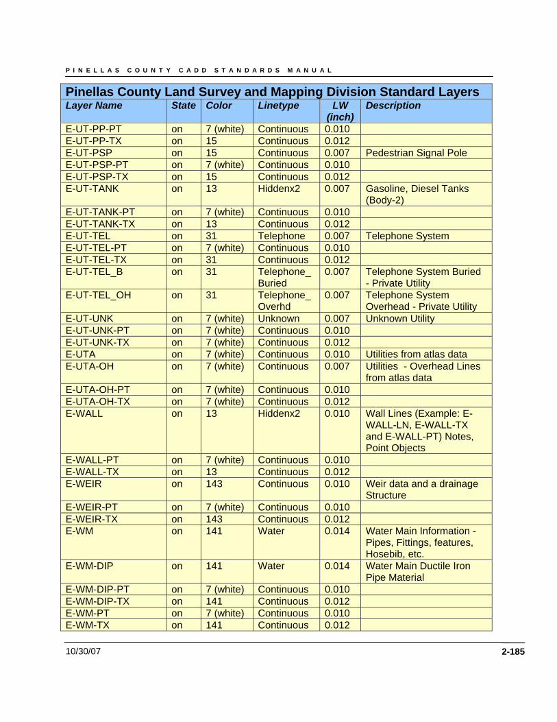
P I N E L L A S C O U N T Y C A D D S T A N D A R D S M A N U A L
10/30/07 2-185
Pinellas County Land Survey and Mapping Division Standard Layers Layer Name State Color Linetype LW
(inch) Description
E-UT-PP-PT on 7 (white) Continuous 0.010 E-UT-PP-TX on 15 Continuous 0.012 E-UT-PSP on 15 Continuous 0.007 Pedestrian Signal Pole E-UT-PSP-PT on 7 (white) Continuous 0.010 E-UT-PSP-TX on 15 Continuous 0.012 E-UT-TANK on 13 Hiddenx2 0.007 Gasoline, Diesel Tanks
(Body-2) E-UT-TANK-PT on 7 (white) Continuous 0.010 E-UT-TANK-TX on 13 Continuous 0.012 E-UT-TEL on 31 Telephone 0.007 Telephone System E-UT-TEL-PT on 7 (white) Continuous 0.010 E-UT-TEL-TX on 31 Continuous 0.012 E-UT-TEL_B on 31 Telephone_
Buried 0.007 Telephone System Buried
- Private Utility E-UT-TEL_OH on 31 Telephone_
Overhd 0.007 Telephone System
Overhead - Private Utility E-UT-UNK on 7 (white) Unknown 0.007 Unknown Utility E-UT-UNK-PT on 7 (white) Continuous 0.010 E-UT-UNK-TX on 7 (white) Continuous 0.012 E-UTA on 7 (white) Continuous 0.010 Utilities from atlas data E-UTA-OH on 7 (white) Continuous 0.007 Utilities - Overhead Lines
from atlas data E-UTA-OH-PT on 7 (white) Continuous 0.010 E-UTA-OH-TX on 7 (white) Continuous 0.012 E-WALL on 13 Hiddenx2 0.010 Wall Lines (Example: E-
WALL-LN, E-WALL-TX and E-WALL-PT) Notes, Point Objects
E-WALL-PT on 7 (white) Continuous 0.010 E-WALL-TX on 13 Continuous 0.012 E-WEIR on 143 Continuous 0.010 Weir data and a drainage
Structure E-WEIR-PT on 7 (white) Continuous 0.010 E-WEIR-TX on 143 Continuous 0.012 E-WM on 141 Water 0.014 Water Main Information -
Pipes, Fittings, features, Hosebib, etc.
E-WM-DIP on 141 Water 0.014 Water Main Ductile Iron Pipe Material
E-WM-DIP-PT on 7 (white) Continuous 0.010 E-WM-DIP-TX on 141 Continuous 0.012 E-WM-PT on 7 (white) Continuous 0.010 E-WM-TX on 141 Continuous 0.012
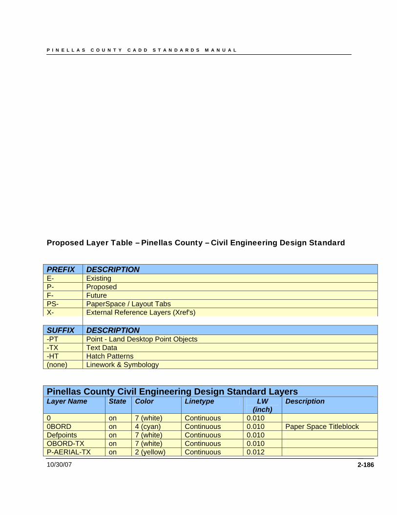
P I N E L L A S C O U N T Y C A D D S T A N D A R D S M A N U A L
10/30/07 2-186
Proposed Layer Table – Pinellas County – Civil Engineering Design Standard
PREFIX DESCRIPTION E- Existing P- Proposed F- Future PS- PaperSpace / Layout Tabs X- External Reference Layers (Xref's) SUFFIX DESCRIPTION -PT Point - Land Desktop Point Objects -TX Text Data -HT Hatch Patterns (none) Linework & Symbology
Pinellas County Civil Engineering Design Standard Layers Layer Name State Color Linetype LW
(inch) Description
0 on 7 (white) Continuous 0.010 0BORD on 4 (cyan) Continuous 0.010 Paper Space Titleblock Defpoints on 7 (white) Continuous 0.010 OBORD-TX on 7 (white) Continuous 0.010 P-AERIAL-TX on 2 (yellow) Continuous 0.012
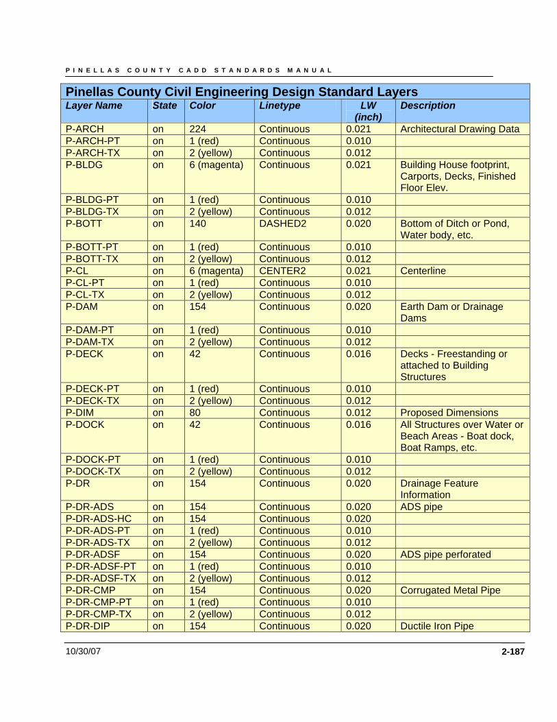
P I N E L L A S C O U N T Y C A D D S T A N D A R D S M A N U A L
10/30/07 2-187
Pinellas County Civil Engineering Design Standard Layers Layer Name State Color Linetype LW
(inch) Description
P-ARCH on 224 Continuous 0.021 Architectural Drawing Data P-ARCH-PT on 1 (red) Continuous 0.010 P-ARCH-TX on 2 (yellow) Continuous 0.012 P-BLDG on 6 (magenta) Continuous 0.021 Building House footprint,
Carports, Decks, Finished Floor Elev.
P-BLDG-PT on 1 (red) Continuous 0.010 P-BLDG-TX on 2 (yellow) Continuous 0.012 P-BOTT on 140 DASHED2 0.020 Bottom of Ditch or Pond,
Water body, etc. P-BOTT-PT on 1 (red) Continuous 0.010 P-BOTT-TX on 2 (yellow) Continuous 0.012 P-CL on 6 (magenta) CENTER2 0.021 Centerline P-CL-PT on 1 (red) Continuous 0.010 P-CL-TX on 2 (yellow) Continuous 0.012 P-DAM on 154 Continuous 0.020 Earth Dam or Drainage
Dams P-DAM-PT on 1 (red) Continuous 0.010 P-DAM-TX on 2 (yellow) Continuous 0.012 P-DECK on 42 Continuous 0.016 Decks - Freestanding or
attached to Building Structures
P-DECK-PT on 1 (red) Continuous 0.010 P-DECK-TX on 2 (yellow) Continuous 0.012 P-DIM on 80 Continuous 0.012 Proposed Dimensions P-DOCK on 42 Continuous 0.016 All Structures over Water or
Beach Areas - Boat dock, Boat Ramps, etc.
P-DOCK-PT on 1 (red) Continuous 0.010 P-DOCK-TX on 2 (yellow) Continuous 0.012 P-DR on 154 Continuous 0.020 Drainage Feature
Information P-DR-ADS on 154 Continuous 0.020 ADS pipe P-DR-ADS-HC on 154 Continuous 0.020 P-DR-ADS-PT on 1 (red) Continuous 0.010 P-DR-ADS-TX on 2 (yellow) Continuous 0.012 P-DR-ADSF on 154 Continuous 0.020 ADS pipe perforated P-DR-ADSF-PT on 1 (red) Continuous 0.010 P-DR-ADSF-TX on 2 (yellow) Continuous 0.012 P-DR-CMP on 154 Continuous 0.020 Corrugated Metal Pipe P-DR-CMP-PT on 1 (red) Continuous 0.010 P-DR-CMP-TX on 2 (yellow) Continuous 0.012 P-DR-DIP on 154 Continuous 0.020 Ductile Iron Pipe
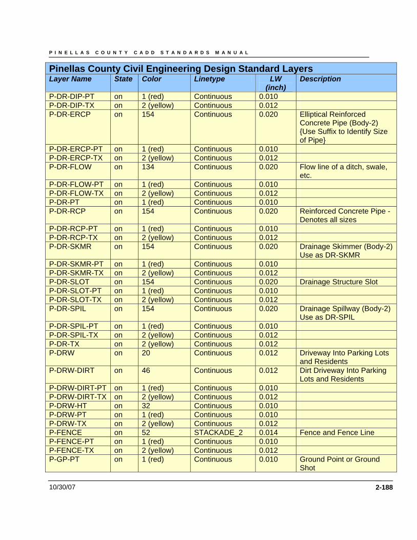
P I N E L L A S C O U N T Y C A D D S T A N D A R D S M A N U A L
10/30/07 2-188
Pinellas County Civil Engineering Design Standard Layers Layer Name State Color Linetype LW
(inch) Description
P-DR-DIP-PT on 1 (red) Continuous 0.010 P-DR-DIP-TX on 2 (yellow) Continuous 0.012 P-DR-ERCP on 154 Continuous 0.020 Elliptical Reinforced
Concrete Pipe (Body-2) {Use Suffix to Identify Size of Pipe}
P-DR-ERCP-PT on 1 (red) Continuous 0.010 P-DR-ERCP-TX on 2 (yellow) Continuous 0.012 P-DR-FLOW on 134 Continuous 0.020 Flow line of a ditch, swale,
etc. P-DR-FLOW-PT on 1 (red) Continuous 0.010 P-DR-FLOW-TX on 2 (yellow) Continuous 0.012 P-DR-PT on 1 (red) Continuous 0.010 P-DR-RCP on 154 Continuous 0.020 Reinforced Concrete Pipe -
Denotes all sizes P-DR-RCP-PT on 1 (red) Continuous 0.010 P-DR-RCP-TX on 2 (yellow) Continuous 0.012 P-DR-SKMR on 154 Continuous 0.020 Drainage Skimmer (Body-2)
Use as DR-SKMR P-DR-SKMR-PT on 1 (red) Continuous 0.010 P-DR-SKMR-TX on 2 (yellow) Continuous 0.012 P-DR-SLOT on 154 Continuous 0.020 Drainage Structure Slot P-DR-SLOT-PT on 1 (red) Continuous 0.010 P-DR-SLOT-TX on 2 (yellow) Continuous 0.012 P-DR-SPIL on 154 Continuous 0.020 Drainage Spillway (Body-2)
Use as DR-SPIL P-DR-SPIL-PT on 1 (red) Continuous 0.010 P-DR-SPIL-TX on 2 (yellow) Continuous 0.012 P-DR-TX on 2 (yellow) Continuous 0.012 P-DRW on 20 Continuous 0.012 Driveway Into Parking Lots
and Residents P-DRW-DIRT on 46 Continuous 0.012 Dirt Driveway Into Parking
Lots and Residents P-DRW-DIRT-PT on 1 (red) Continuous 0.010 P-DRW-DIRT-TX on 2 (yellow) Continuous 0.012 P-DRW-HT on 32 Continuous 0.010 P-DRW-PT on 1 (red) Continuous 0.010 P-DRW-TX on 2 (yellow) Continuous 0.012 P-FENCE on 52 STACKADE_2 0.014 Fence and Fence Line P-FENCE-PT on 1 (red) Continuous 0.010 P-FENCE-TX on 2 (yellow) Continuous 0.012 P-GP-PT on 1 (red) Continuous 0.010 Ground Point or Ground
Shot
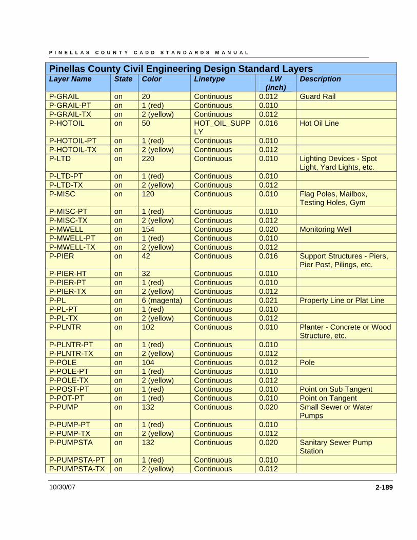
P I N E L L A S C O U N T Y C A D D S T A N D A R D S M A N U A L
10/30/07 2-189
Pinellas County Civil Engineering Design Standard Layers Layer Name State Color Linetype LW
(inch) Description
P-GRAIL on 20 Continuous 0.012 Guard Rail P-GRAIL-PT on 1 (red) Continuous 0.010 P-GRAIL-TX on 2 (yellow) Continuous 0.012 P-HOTOIL on 50 HOT_OIL_SUPP
LY 0.016 Hot Oil Line
P-HOTOIL-PT on 1 (red) Continuous 0.010 P-HOTOIL-TX on 2 (yellow) Continuous 0.012 P-LTD on 220 Continuous 0.010 Lighting Devices - Spot
Light, Yard Lights, etc. P-LTD-PT on 1 (red) Continuous 0.010 P-LTD-TX on 2 (yellow) Continuous 0.012 P-MISC on 120 Continuous 0.010 Flag Poles, Mailbox,
Testing Holes, Gym P-MISC-PT on 1 (red) Continuous 0.010 P-MISC-TX on 2 (yellow) Continuous 0.012 P-MWELL on 154 Continuous 0.020 Monitoring Well P-MWELL-PT on 1 (red) Continuous 0.010 P-MWELL-TX on 2 (yellow) Continuous 0.012 P-PIER on 42 Continuous 0.016 Support Structures - Piers,
Pier Post, Pilings, etc. P-PIER-HT on 32 Continuous 0.010 P-PIER-PT on 1 (red) Continuous 0.010 P-PIER-TX on 2 (yellow) Continuous 0.012 P-PL on 6 (magenta) Continuous 0.021 Property Line or Plat Line P-PL-PT on 1 (red) Continuous 0.010 P-PL-TX on 2 (yellow) Continuous 0.012 P-PLNTR on 102 Continuous 0.010 Planter - Concrete or Wood
Structure, etc. P-PLNTR-PT on 1 (red) Continuous 0.010 P-PLNTR-TX on 2 (yellow) Continuous 0.012 P-POLE on 104 Continuous 0.012 Pole P-POLE-PT on 1 (red) Continuous 0.010 P-POLE-TX on 2 (yellow) Continuous 0.012 P-POST-PT on 1 (red) Continuous 0.010 Point on Sub Tangent P-POT-PT on 1 (red) Continuous 0.010 Point on Tangent P-PUMP on 132 Continuous 0.020 Small Sewer or Water
Pumps P-PUMP-PT on 1 (red) Continuous 0.010 P-PUMP-TX on 2 (yellow) Continuous 0.012 P-PUMPSTA on 132 Continuous 0.020 Sanitary Sewer Pump
Station P-PUMPSTA-PT on 1 (red) Continuous 0.010 P-PUMPSTA-TX on 2 (yellow) Continuous 0.012
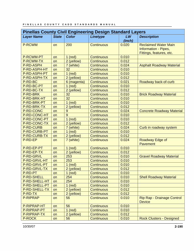
P I N E L L A S C O U N T Y C A D D S T A N D A R D S M A N U A L
10/30/07 2-190
Pinellas County Civil Engineering Design Standard Layers Layer Name State Color Linetype LW
(inch) Description
P-RCWM on 200 Continuous 0.020 Reclaimed Water Main Information - Pipes, Fittings, features, etc.
P-RCWM-PT on 1 (red) Continuous 0.010 P-RCWM-TX on 2 (yellow) Continuous 0.012 P-RD-ASPH on 7 (white) Continuous 0.024 Asphalt Roadway Material P-RD-ASPH-HT on 32 Continuous 0.010 P-RD-ASPH-PT on 1 (red) Continuous 0.010 P-RD-ASPH-TX on 2 (yellow) Continuous 0.012 P-RD-BC on 6 (magenta) Continuous 0.021 Roadway back-of-curb P-RD-BC-PT on 1 (red) Continuous 0.010 P-RD-BC-TX on 2 (yellow) Continuous 0.012 P-RD-BRK on 32 Continuous 0.010 Brick Roadway Material P-RD-BRK-HT on 32 Continuous 0.010 P-RD-BRK-PT on 1 (red) Continuous 0.010 P-RD-BRK-TX on 2 (yellow) Continuous 0.012 P-RD-CONC on 9 Continuous 0.024 Concrete Roadway Material P-RD-CONC-HT on 9 Continuous 0.010 P-RD-CONC-PT on 1 (red) Continuous 0.010 P-RD-CONC-TX on 2 (yellow) Continuous 0.012 P-RD-CURB on 7 (white) Continuous 0.024 Curb in roadway system P-RD-CURB-PT on 1 (red) Continuous 0.010 P-RD-CURB-TX on 2 (yellow) Continuous 0.012 P-RD-EP on 7 (white) Continuous 0.024 Roadway Edge of
Pavement P-RD-EP-PT on 1 (red) Continuous 0.010 P-RD-EP-TX on 2 (yellow) Continuous 0.012 P-RD-GRVL on 253 Continuous 0.010 Gravel Roadway Material P-RD-GRVL-HT on 253 Continuous 0.010 P-RD-GRVL-PT on 1 (red) Continuous 0.010 P-RD-GRVL-TX on 2 (yellow) Continuous 0.012 P-RD-PT on 1 (red) Continuous 0.010 P-RD-SHELL on 254 Continuous 0.010 Shell Roadway Material P-RD-SHELL-HT on 254 Continuous 0.010 P-RD-SHELL-PT on 1 (red) Continuous 0.010 P-RD-SHELL-TX on 2 (yellow) Continuous 0.012 P-RD-TX on 2 (yellow) Continuous 0.012 P-RIPRAP on 56 Continuous 0.010 Rip Rap - Drainage Control
Device P-RIPRAP-HT on 56 Continuous 0.010 P-RIPRAP-PT on 1 (red) Continuous 0.010 P-RIPRAP-TX on 2 (yellow) Continuous 0.012 P-ROCK on 56 Continuous 0.010 Rock Clusters - Designed
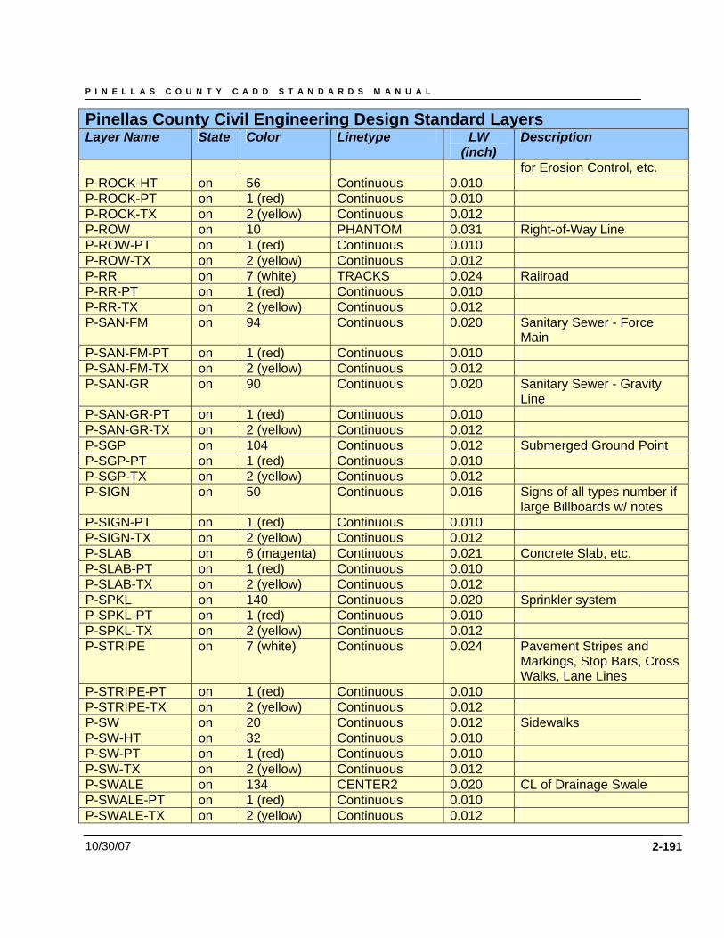
P I N E L L A S C O U N T Y C A D D S T A N D A R D S M A N U A L
10/30/07 2-191
Pinellas County Civil Engineering Design Standard Layers Layer Name State Color Linetype LW
(inch) Description
for Erosion Control, etc. P-ROCK-HT on 56 Continuous 0.010 P-ROCK-PT on 1 (red) Continuous 0.010 P-ROCK-TX on 2 (yellow) Continuous 0.012 P-ROW on 10 PHANTOM 0.031 Right-of-Way Line P-ROW-PT on 1 (red) Continuous 0.010 P-ROW-TX on 2 (yellow) Continuous 0.012 P-RR on 7 (white) TRACKS 0.024 Railroad P-RR-PT on 1 (red) Continuous 0.010 P-RR-TX on 2 (yellow) Continuous 0.012 P-SAN-FM on 94 Continuous 0.020 Sanitary Sewer - Force
Main P-SAN-FM-PT on 1 (red) Continuous 0.010 P-SAN-FM-TX on 2 (yellow) Continuous 0.012 P-SAN-GR on 90 Continuous 0.020 Sanitary Sewer - Gravity
Line P-SAN-GR-PT on 1 (red) Continuous 0.010 P-SAN-GR-TX on 2 (yellow) Continuous 0.012 P-SGP on 104 Continuous 0.012 Submerged Ground Point P-SGP-PT on 1 (red) Continuous 0.010 P-SGP-TX on 2 (yellow) Continuous 0.012 P-SIGN on 50 Continuous 0.016 Signs of all types number if
large Billboards w/ notes P-SIGN-PT on 1 (red) Continuous 0.010 P-SIGN-TX on 2 (yellow) Continuous 0.012 P-SLAB on 6 (magenta) Continuous 0.021 Concrete Slab, etc. P-SLAB-PT on 1 (red) Continuous 0.010 P-SLAB-TX on 2 (yellow) Continuous 0.012 P-SPKL on 140 Continuous 0.020 Sprinkler system P-SPKL-PT on 1 (red) Continuous 0.010 P-SPKL-TX on 2 (yellow) Continuous 0.012 P-STRIPE on 7 (white) Continuous 0.024 Pavement Stripes and
Markings, Stop Bars, Cross Walks, Lane Lines
P-STRIPE-PT on 1 (red) Continuous 0.010 P-STRIPE-TX on 2 (yellow) Continuous 0.012 P-SW on 20 Continuous 0.012 Sidewalks P-SW-HT on 32 Continuous 0.010 P-SW-PT on 1 (red) Continuous 0.010 P-SW-TX on 2 (yellow) Continuous 0.012 P-SWALE on 134 CENTER2 0.020 CL of Drainage Swale P-SWALE-PT on 1 (red) Continuous 0.010 P-SWALE-TX on 2 (yellow) Continuous 0.012
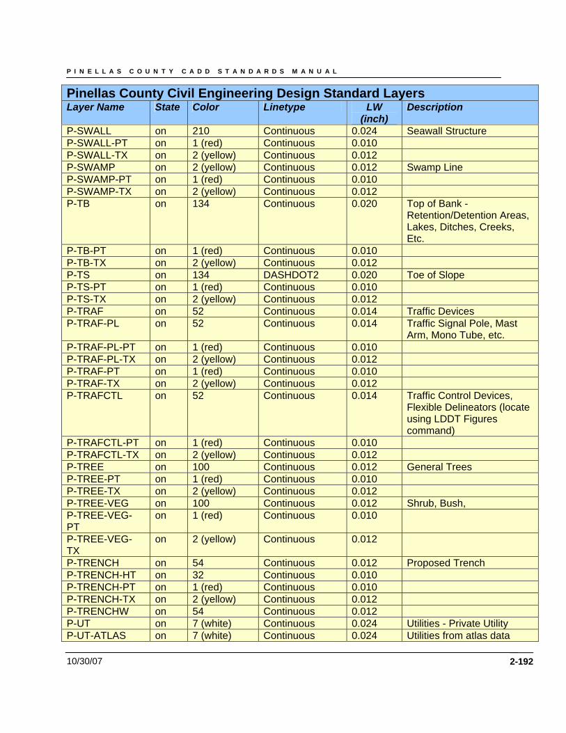
P I N E L L A S C O U N T Y C A D D S T A N D A R D S M A N U A L
10/30/07 2-192
Pinellas County Civil Engineering Design Standard Layers Layer Name State Color Linetype LW
(inch) Description
P-SWALL on 210 Continuous 0.024 Seawall Structure P-SWALL-PT on 1 (red) Continuous 0.010 P-SWALL-TX on 2 (yellow) Continuous 0.012 P-SWAMP on 2 (yellow) Continuous 0.012 Swamp Line P-SWAMP-PT on 1 (red) Continuous 0.010 P-SWAMP-TX on 2 (yellow) Continuous 0.012 P-TB on 134 Continuous 0.020 Top of Bank -
Retention/Detention Areas, Lakes, Ditches, Creeks, Etc.
P-TB-PT on 1 (red) Continuous 0.010 P-TB-TX on 2 (yellow) Continuous 0.012 P-TS on 134 DASHDOT2 0.020 Toe of Slope P-TS-PT on 1 (red) Continuous 0.010 P-TS-TX on 2 (yellow) Continuous 0.012 P-TRAF on 52 Continuous 0.014 Traffic Devices P-TRAF-PL on 52 Continuous 0.014 Traffic Signal Pole, Mast
Arm, Mono Tube, etc. P-TRAF-PL-PT on 1 (red) Continuous 0.010 P-TRAF-PL-TX on 2 (yellow) Continuous 0.012 P-TRAF-PT on 1 (red) Continuous 0.010 P-TRAF-TX on 2 (yellow) Continuous 0.012 P-TRAFCTL on 52 Continuous 0.014 Traffic Control Devices,
Flexible Delineators (locate using LDDT Figures command)
P-TRAFCTL-PT on 1 (red) Continuous 0.010 P-TRAFCTL-TX on 2 (yellow) Continuous 0.012 P-TREE on 100 Continuous 0.012 General Trees P-TREE-PT on 1 (red) Continuous 0.010 P-TREE-TX on 2 (yellow) Continuous 0.012 P-TREE-VEG on 100 Continuous 0.012 Shrub, Bush, P-TREE-VEG-PT
on 1 (red) Continuous 0.010
P-TREE-VEG-TX
on 2 (yellow) Continuous 0.012
P-TRENCH on 54 Continuous 0.012 Proposed Trench P-TRENCH-HT on 32 Continuous 0.010 P-TRENCH-PT on 1 (red) Continuous 0.010 P-TRENCH-TX on 2 (yellow) Continuous 0.012 P-TRENCHW on 54 Continuous 0.012 P-UT on 7 (white) Continuous 0.024 Utilities - Private Utility P-UT-ATLAS on 7 (white) Continuous 0.024 Utilities from atlas data
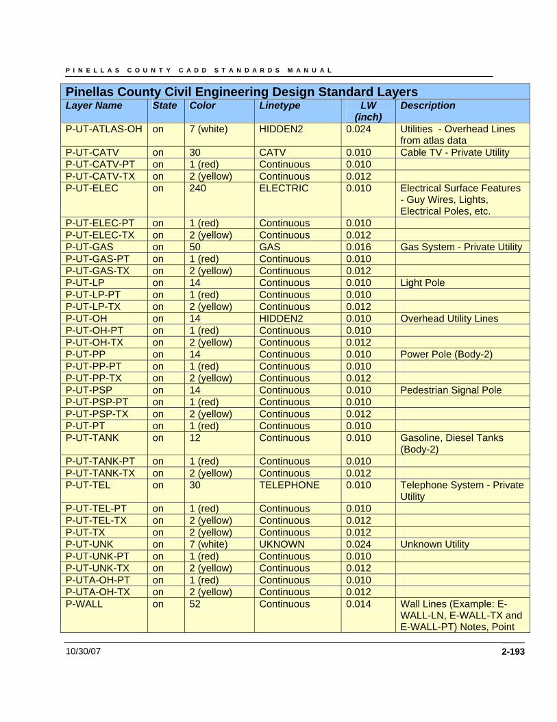
P I N E L L A S C O U N T Y C A D D S T A N D A R D S M A N U A L
10/30/07 2-193
Pinellas County Civil Engineering Design Standard Layers Layer Name State Color Linetype LW
(inch) Description
P-UT-ATLAS-OH on 7 (white) HIDDEN2 0.024 Utilities - Overhead Lines from atlas data
P-UT-CATV on 30 CATV 0.010 Cable TV - Private Utility P-UT-CATV-PT on 1 (red) Continuous 0.010 P-UT-CATV-TX on 2 (yellow) Continuous 0.012 P-UT-ELEC on 240 ELECTRIC 0.010 Electrical Surface Features
- Guy Wires, Lights, Electrical Poles, etc.
P-UT-ELEC-PT on 1 (red) Continuous 0.010 P-UT-ELEC-TX on 2 (yellow) Continuous 0.012 P-UT-GAS on 50 GAS 0.016 Gas System - Private Utility P-UT-GAS-PT on 1 (red) Continuous 0.010 P-UT-GAS-TX on 2 (yellow) Continuous 0.012 P-UT-LP on 14 Continuous 0.010 Light Pole P-UT-LP-PT on 1 (red) Continuous 0.010 P-UT-LP-TX on 2 (yellow) Continuous 0.012 P-UT-OH on 14 HIDDEN2 0.010 Overhead Utility Lines P-UT-OH-PT on 1 (red) Continuous 0.010 P-UT-OH-TX on 2 (yellow) Continuous 0.012 P-UT-PP on 14 Continuous 0.010 Power Pole (Body-2) P-UT-PP-PT on 1 (red) Continuous 0.010 P-UT-PP-TX on 2 (yellow) Continuous 0.012 P-UT-PSP on 14 Continuous 0.010 Pedestrian Signal Pole P-UT-PSP-PT on 1 (red) Continuous 0.010 P-UT-PSP-TX on 2 (yellow) Continuous 0.012 P-UT-PT on 1 (red) Continuous 0.010 P-UT-TANK on 12 Continuous 0.010 Gasoline, Diesel Tanks
(Body-2) P-UT-TANK-PT on 1 (red) Continuous 0.010 P-UT-TANK-TX on 2 (yellow) Continuous 0.012 P-UT-TEL on 30 TELEPHONE 0.010 Telephone System - Private
Utility P-UT-TEL-PT on 1 (red) Continuous 0.010 P-UT-TEL-TX on 2 (yellow) Continuous 0.012 P-UT-TX on 2 (yellow) Continuous 0.012 P-UT-UNK on 7 (white) UKNOWN 0.024 Unknown Utility P-UT-UNK-PT on 1 (red) Continuous 0.010 P-UT-UNK-TX on 2 (yellow) Continuous 0.012 P-UTA-OH-PT on 1 (red) Continuous 0.010 P-UTA-OH-TX on 2 (yellow) Continuous 0.012 P-WALL on 52 Continuous 0.014 Wall Lines (Example: E-
WALL-LN, E-WALL-TX and E-WALL-PT) Notes, Point
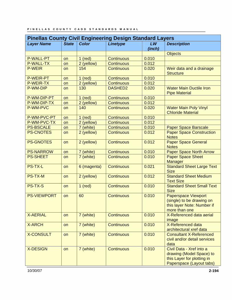
P I N E L L A S C O U N T Y C A D D S T A N D A R D S M A N U A L
10/30/07 2-194
Pinellas County Civil Engineering Design Standard Layers Layer Name State Color Linetype LW
(inch) Description
Objects P-WALL-PT on 1 (red) Continuous 0.010 P-WALL-TX on 2 (yellow) Continuous 0.012 P-WEIR on 154 Continuous 0.020 Weir data and a drainage
Structure P-WEIR-PT on 1 (red) Continuous 0.010 P-WEIR-TX on 2 (yellow) Continuous 0.012 P-WM-DIP on 130 DASHED2 0.020 Water Main Ductile Iron
Pipe Material P-WM-DIP-PT on 1 (red) Continuous 0.010 P-WM-DIP-TX on 2 (yellow) Continuous 0.012 P-WM-PVC on 140 Continuous 0.020 Water Main Poly Vinyl
Chloride Material P-WM-PVC-PT on 1 (red) Continuous 0.010 P-WM-PVC-TX on 2 (yellow) Continuous 0.012 PS-BSCALE on 7 (white) Continuous 0.010 Paper Space Barscale PS-CNOTES on 2 (yellow) Continuous 0.012 Paper Space Construction
Notes PS-GNOTES on 2 (yellow) Continuous 0.012 Paper Space General
Notes PS-NARROW on 7 (white) Continuous 0.010 Paper Space North Arrow PS-SHEET on 7 (white) Continuous 0.010 Paper Space Sheet
Manager PS-TX-L on 6 (magenta) Continuous 0.021 Standard Sheet Large Text
Size PS-TX-M on 2 (yellow) Continuous 0.012 Standard Sheet Medium
Text Size PS-TX-S on 1 (red) Continuous 0.010 Standard Sheet Small Text
Size PS-VIEWPORT on 60 Continuous 0.010 Paperspace Viewport
(single) to be drawing on this layer Note: Number if more than one
X-AERIAL on 7 (white) Continuous 0.010 X-Referenced data aerial image
X-ARCH on 7 (white) Continuous 0.010 X-Referenced data architectural xref data
X-CONSULT on 7 (white) Continuous 0.010 Consultant X-Referenced civil and/or detail services data
X-DESIGN on 7 (white) Continuous 0.010 Civil Data - Xref into a drawing (Model Space) to this Layer for plotting in Paperspace (Layout tabs)
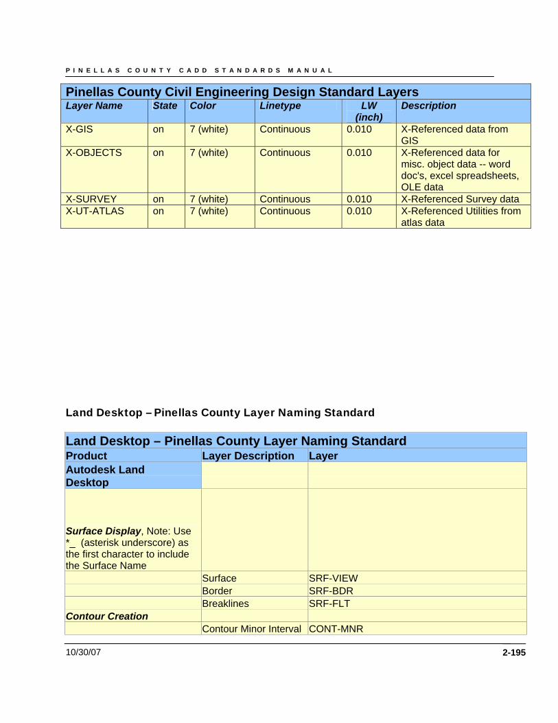
P I N E L L A S C O U N T Y C A D D S T A N D A R D S M A N U A L
10/30/07 2-195
Pinellas County Civil Engineering Design Standard Layers Layer Name State Color Linetype LW
(inch) Description
X-GIS on 7 (white) Continuous 0.010 X-Referenced data from GIS
X-OBJECTS on 7 (white) Continuous 0.010 X-Referenced data for misc. object data -- word doc's, excel spreadsheets, OLE data
X-SURVEY on 7 (white) Continuous 0.010 X-Referenced Survey data X-UT-ATLAS on 7 (white) Continuous 0.010 X-Referenced Utilities from
atlas data Land Desktop – Pinellas County Layer Naming Standard Land Desktop – Pinellas County Layer Naming Standard Product Layer Description Layer Autodesk Land Desktop
Surface Display, Note: Use *_ (asterisk underscore) as the first character to include the Surface Name Surface SRF-VIEW Border SRF-BDR Breaklines SRF-FLT Contour Creation Contour Minor Interval CONT-MNR
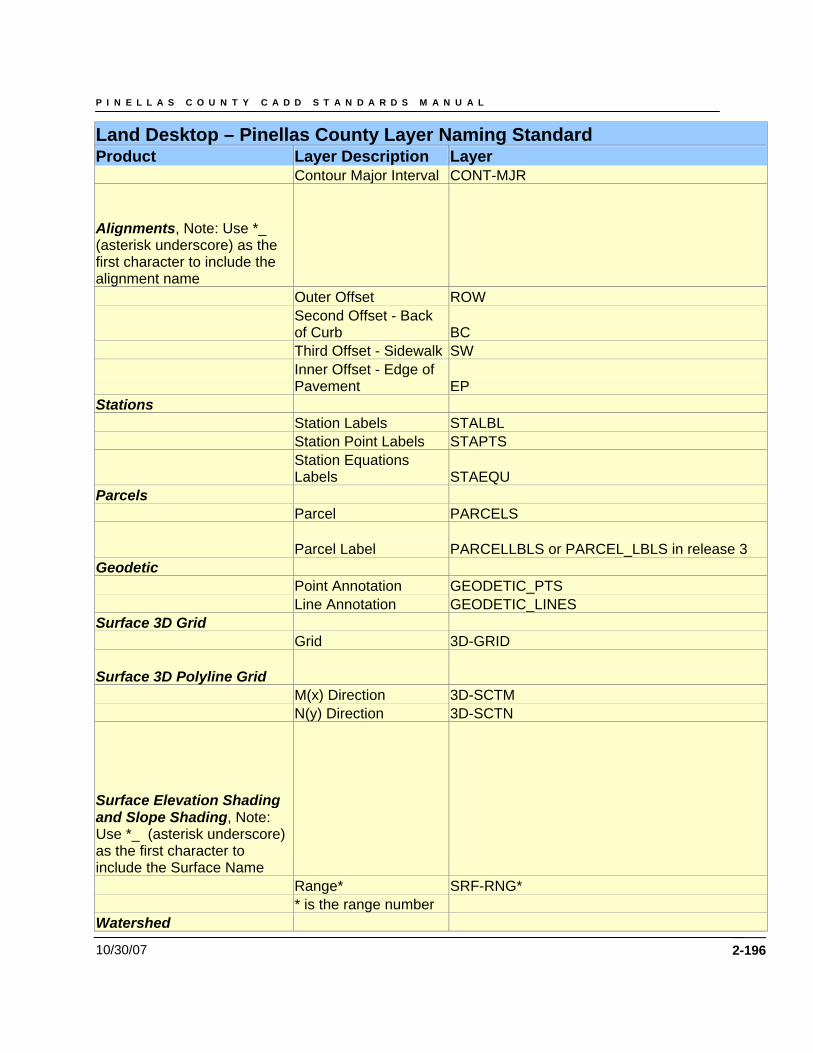
P I N E L L A S C O U N T Y C A D D S T A N D A R D S M A N U A L
10/30/07 2-196
Land Desktop – Pinellas County Layer Naming Standard Product Layer Description Layer Contour Major Interval CONT-MJR
Alignments, Note: Use *_ (asterisk underscore) as the first character to include the alignment name Outer Offset ROW
Second Offset - Back of Curb BC
Third Offset - Sidewalk SW
Inner Offset - Edge of Pavement EP
Stations Station Labels STALBL Station Point Labels STAPTS
Station Equations Labels STAEQU
Parcels Parcel PARCELS
Parcel Label PARCELLBLS or PARCEL_LBLS in release 3 Geodetic Point Annotation GEODETIC_PTS Line Annotation GEODETIC_LINES Surface 3D Grid Grid 3D-GRID
Surface 3D Polyline Grid M(x) Direction 3D-SCTM N(y) Direction 3D-SCTN
Surface Elevation Shading and Slope Shading, Note: Use *_ (asterisk underscore) as the first character to include the Surface Name Range* SRF-RNG* * is the range number Watershed
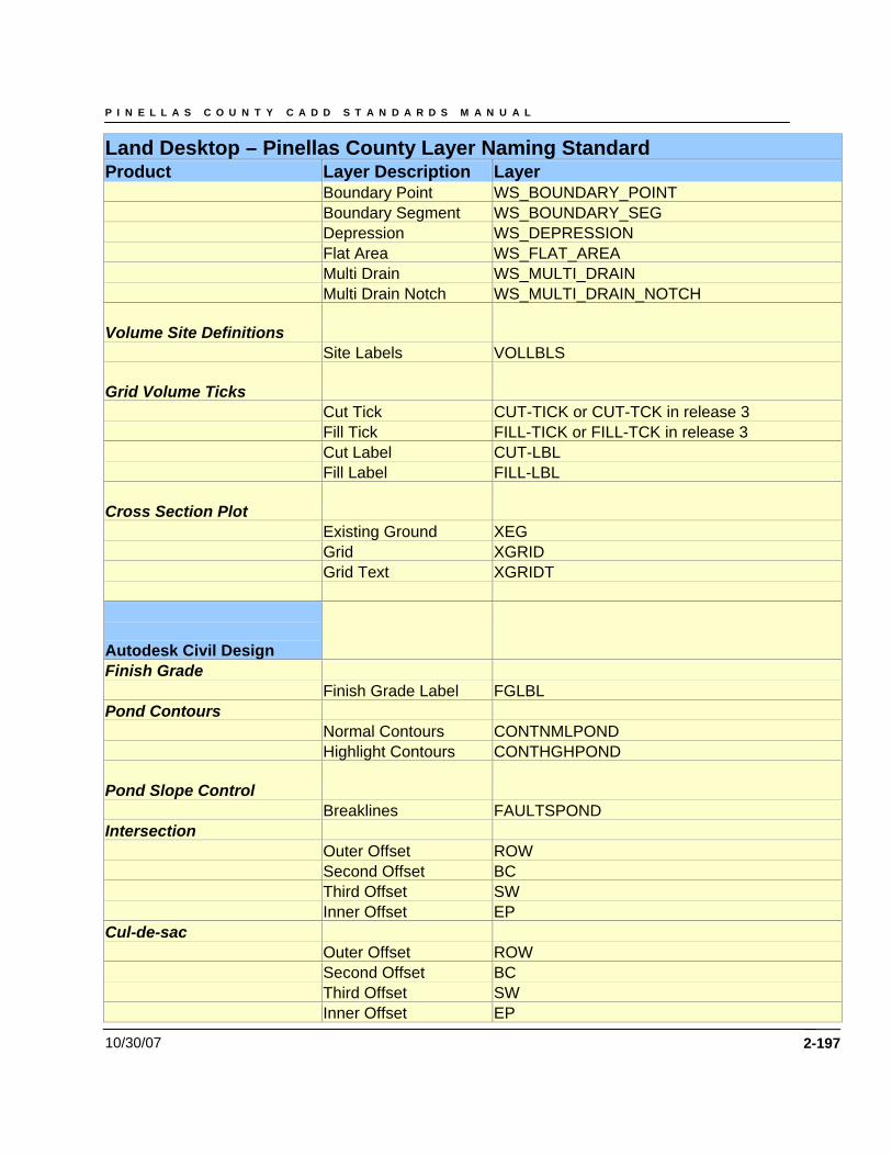
P I N E L L A S C O U N T Y C A D D S T A N D A R D S M A N U A L
10/30/07 2-197
Land Desktop – Pinellas County Layer Naming Standard Product Layer Description Layer Boundary Point WS_BOUNDARY_POINT Boundary Segment WS_BOUNDARY_SEG Depression WS_DEPRESSION Flat Area WS_FLAT_AREA Multi Drain WS_MULTI_DRAIN Multi Drain Notch WS_MULTI_DRAIN_NOTCH
Volume Site Definitions Site Labels VOLLBLS
Grid Volume Ticks Cut Tick CUT-TICK or CUT-TCK in release 3 Fill Tick FILL-TICK or FILL-TCK in release 3 Cut Label CUT-LBL Fill Label FILL-LBL
Cross Section Plot Existing Ground XEG Grid XGRID Grid Text XGRIDT Autodesk Civil Design
Finish Grade Finish Grade Label FGLBL Pond Contours Normal Contours CONTNMLPOND Highlight Contours CONTHGHPOND
Pond Slope Control Breaklines FAULTSPOND Intersection Outer Offset ROW Second Offset BC Third Offset SW Inner Offset EP Cul-de-sac Outer Offset ROW Second Offset BC Third Offset SW Inner Offset EP
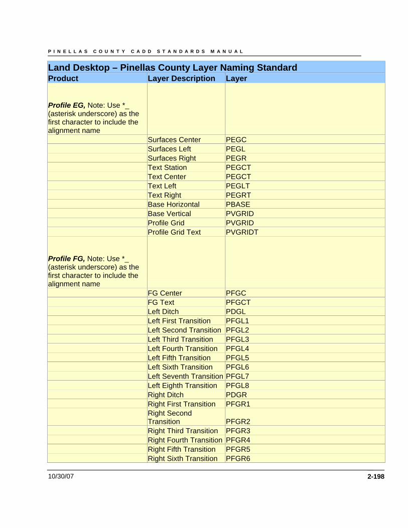
P I N E L L A S C O U N T Y C A D D S T A N D A R D S M A N U A L
10/30/07 2-198
Land Desktop – Pinellas County Layer Naming Standard Product Layer Description Layer
Profile EG, Note: Use *_ (asterisk underscore) as the first character to include the alignment name Surfaces Center PEGC Surfaces Left PEGL Surfaces Right PEGR Text Station PEGCT Text Center PEGCT Text Left PEGLT Text Right PEGRT Base Horizontal PBASE Base Vertical PVGRID Profile Grid PVGRID Profile Grid Text PVGRIDT
Profile FG, Note: Use *_ (asterisk underscore) as the first character to include the alignment name FG Center PFGC FG Text PFGCT Left Ditch PDGL Left First Transition PFGL1 Left Second Transition PFGL2 Left Third Transition PFGL3 Left Fourth Transition PFGL4 Left Fifth Transition PFGL5 Left Sixth Transition PFGL6 Left Seventh Transition PFGL7 Left Eighth Transition PFGL8 Right Ditch PDGR Right First Transition PFGR1
Right Second Transition PFGR2
Right Third Transition PFGR3 Right Fourth Transition PFGR4 Right Fifth Transition PFGR5 Right Sixth Transition PFGR6
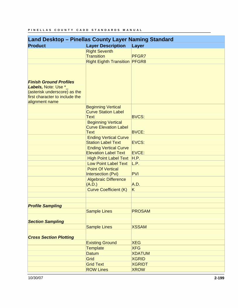
P I N E L L A S C O U N T Y C A D D S T A N D A R D S M A N U A L
10/30/07 2-199
Land Desktop – Pinellas County Layer Naming Standard Product Layer Description Layer
Right Seventh Transition PFGR7
Right Eighth Transition PFGR8
Finish Ground Profiles Labels, Note: Use *_ (asterisk underscore) as the first character to include the alignment name
Beginning Vertical Curve Station Label Text BVCS:
Beginning Vertical Curve Elevation Label Text BVCE:
Ending Vertical Curve Station Label Text EVCS:
Ending Vertical Curve Elevation Label Text EVCE:
High Point Label Text H.P. Low Point Label Text L.P.
Point Of Vertical Intersection (Pvi) PVI
Algebraic Difference (A.D.) A.D.
Curve Coefficient (K) K Profile Sampling Sample Lines PROSAM
Section Sampling Sample Lines XSSAM
Cross Section Plotting Existing Ground XEG Template XFG Datum XDATUM Grid XGRID Grid Text XGRIDT ROW Lines XROW
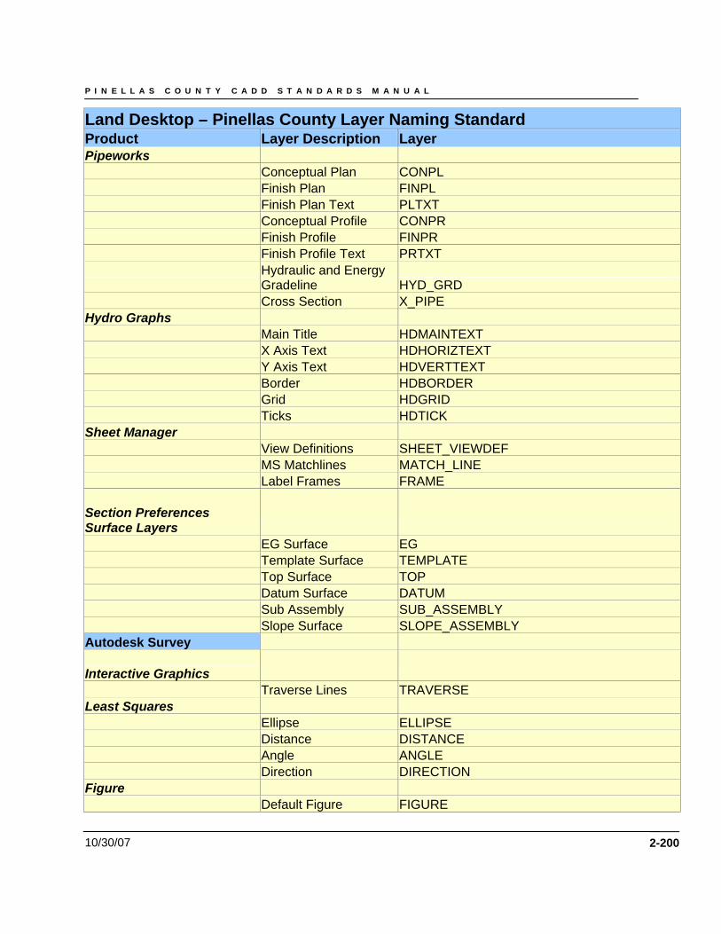
P I N E L L A S C O U N T Y C A D D S T A N D A R D S M A N U A L
10/30/07 2-200
Land Desktop – Pinellas County Layer Naming Standard Product Layer Description Layer Pipeworks Conceptual Plan CONPL Finish Plan FINPL Finish Plan Text PLTXT Conceptual Profile CONPR Finish Profile FINPR Finish Profile Text PRTXT
Hydraulic and Energy Gradeline HYD_GRD
Cross Section X_PIPE Hydro Graphs Main Title HDMAINTEXT X Axis Text HDHORIZTEXT Y Axis Text HDVERTTEXT Border HDBORDER Grid HDGRID Ticks HDTICK Sheet Manager View Definitions SHEET_VIEWDEF MS Matchlines MATCH_LINE Label Frames FRAME
Section Preferences Surface Layers EG Surface EG Template Surface TEMPLATE Top Surface TOP Datum Surface DATUM Sub Assembly SUB_ASSEMBLY Slope Surface SLOPE_ASSEMBLY Autodesk Survey
Interactive Graphics Traverse Lines TRAVERSE Least Squares Ellipse ELLIPSE Distance DISTANCE Angle ANGLE Direction DIRECTION Figure Default Figure FIGURE
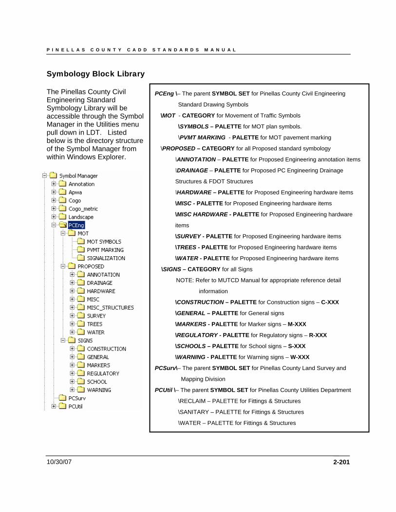
P I N E L L A S C O U N T Y C A D D S T A N D A R D S M A N U A L
10/30/07
Symbology Block Library The Pinellas County Civil Engineering Standard Symbology Library will be accessible through the Symbol Manager in the Utilities menu pull down in LDT. Listed below is the directory structure of the Symbol Manager from within Windows Explorer.
PCEng \– The parent SYMBOL SET for Pinellas County Civil Engineering
Standard Drawing Symbols
\MOT - CATEGORY for Movement of Traffic Symbols
\SYMBOLS – PALETTE for MOT plan symbols.
\PVMT MARKING - PALETTE for MOT pavement marking
\PROPOSED – CATEGORY for all Proposed standard symbology
\ANNOTATION – PALETTE for Proposed Engineering annotation items
\DRAINAGE – PALETTE for Proposed PC Engineering Drainage
Structures & FDOT Structures
\HARDWARE – PALETTE for Proposed Engineering hardware items
\MISC - PALETTE for Proposed Engineering hardware items
\MISC HARDWARE - PALETTE for Proposed Engineering hardware
items
\SURVEY - PALETTE for Proposed Engineering hardware items
\TREES - PALETTE for Proposed Engineering hardware items
\WATER - PALETTE for Proposed Engineering hardware items
\SIGNS – CATEGORY for all Signs
NOTE: Refer to MUTCD Manual for appropriate reference detail
information
\CONSTRUCTION – PALETTE for Construction signs – C-XXX
\GENERAL – PALETTE for General signs
\MARKERS - PALETTE for Marker signs – M-XXX
\REGULATORY - PALETTE for Regulatory signs – R-XXX
\SCHOOLS – PALETTE for School signs – S-XXX
\WARNING - PALETTE for Warning signs – W-XXX
PCSurv\– The parent SYMBOL SET for Pinellas County Land Survey and
Mapping Division
PCUtil \– The parent SYMBOL SET for Pinellas County Utilities Department
\RECLAIM – PALETTE for Fittings & Structures
\SANITARY – PALETTE for Fittings & Structures
\WATER – PALETTE for Fittings & Structures
2-201
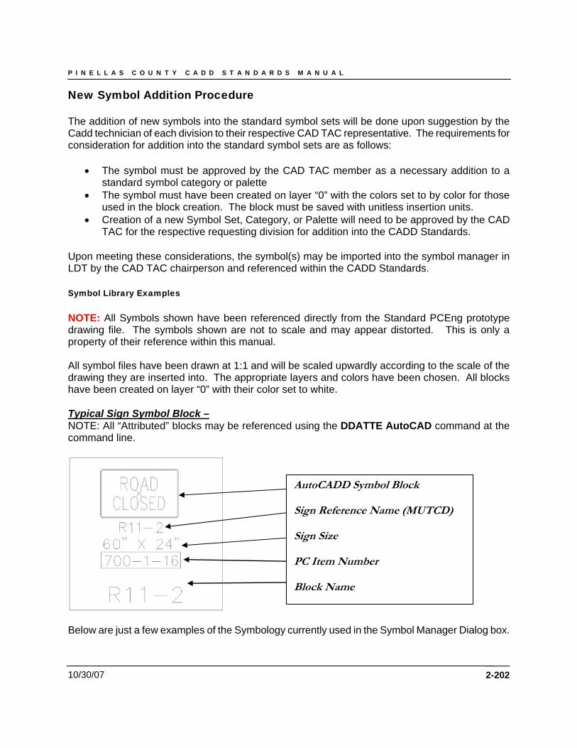
P I N E L L A S C O U N T Y C A D D S T A N D A R D S M A N U A L
10/30/07
New Symbol Addition Procedure The addition of new symbols into the standard symbol sets will be done upon suggestion by the Cadd technician of each division to their respective CAD TAC representative. The requirements for consideration for addition into the standard symbol sets are as follows:
• The symbol must be approved by the CAD TAC member as a necessary addition to a standard symbol category or palette
• The symbol must have been created on layer “0” with the colors set to by color for those used in the block creation. The block must be saved with unitless insertion units.
• Creation of a new Symbol Set, Category, or Palette will need to be approved by the CAD TAC for the respective requesting division for addition into the CADD Standards.
Upon meeting these considerations, the symbol(s) may be imported into the symbol manager in LDT by the CAD TAC chairperson and referenced within the CADD Standards. Symbol Library Examples NOTE: All Symbols shown have been referenced directly from the Standard PCEng prototype drawing file. The symbols shown are not to scale and may appear distorted. This is only a property of their reference within this manual. All symbol files have been drawn at 1:1 and will be scaled upwardly according to the scale of the drawing they are inserted into. The appropriate layers and colors have been chosen. All blocks have been created on layer “0” with their color set to white. Typical Sign Symbol Block – NOTE: All “Attributed” blocks may be referenced using the DDATTE AutoCAD command at the command line.
AutoCADD Symbol Block Sign Reference Name (MUTCD) Sign Size PC Item Number Block Name
Below are just a few examples of the Symbology currently used in the Symbol Manager Dialog box.
2-202
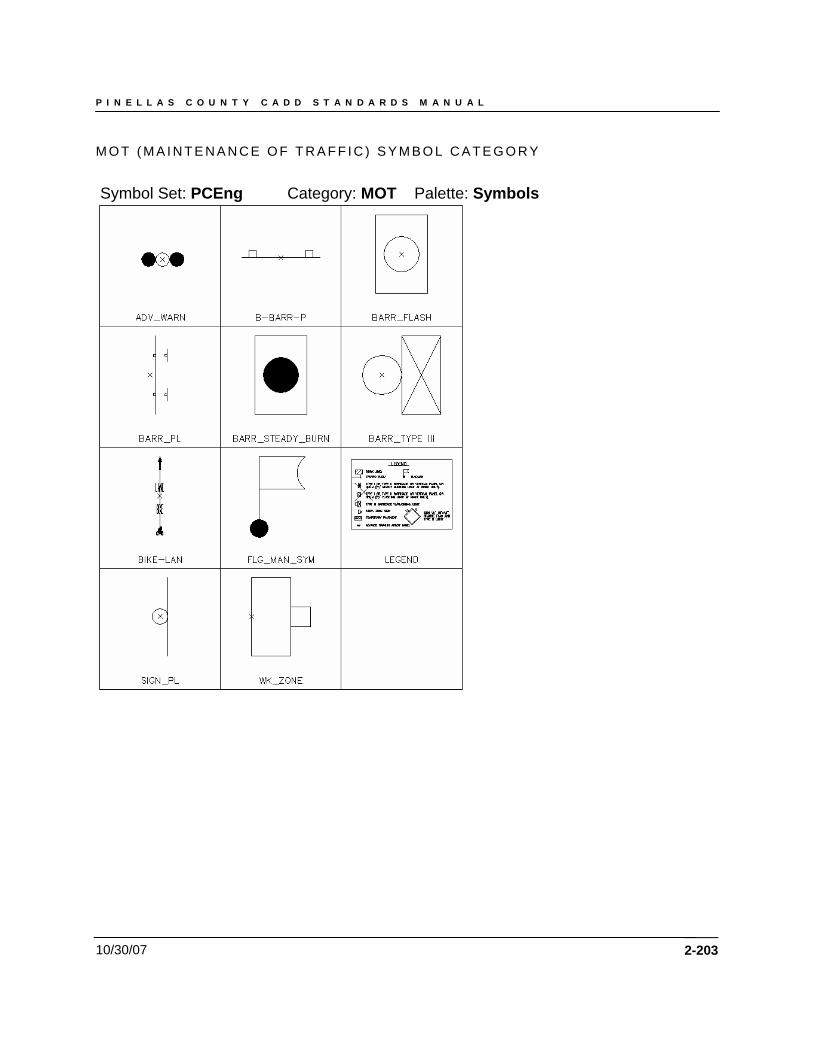
P I N E L L A S C O U N T Y C A D D S T A N D A R D S M A N U A L
10/30/07
M O T ( M A I N T E N A N C E O F T R A F F I C ) S Y M B O L C A T E G O R Y
Symbol Set: PCEng Category: MOT Palette: Symbols
2-203
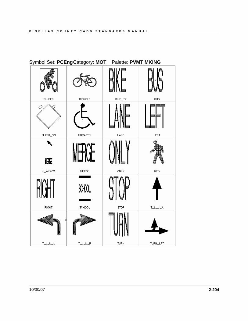
P I N E L L A S C O U N T Y C A D D S T A N D A R D S M A N U A L
10/30/07
Symbol Set: PCEng Category: MOT Palette: PVMT MKING
2-204
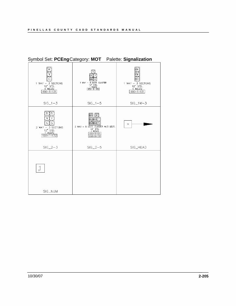
P I N E L L A S C O U N T Y C A D D S T A N D A R D S M A N U A L
10/30/07
Symbol Set: PCEng Category: MOT Palette: Signalization
2-205
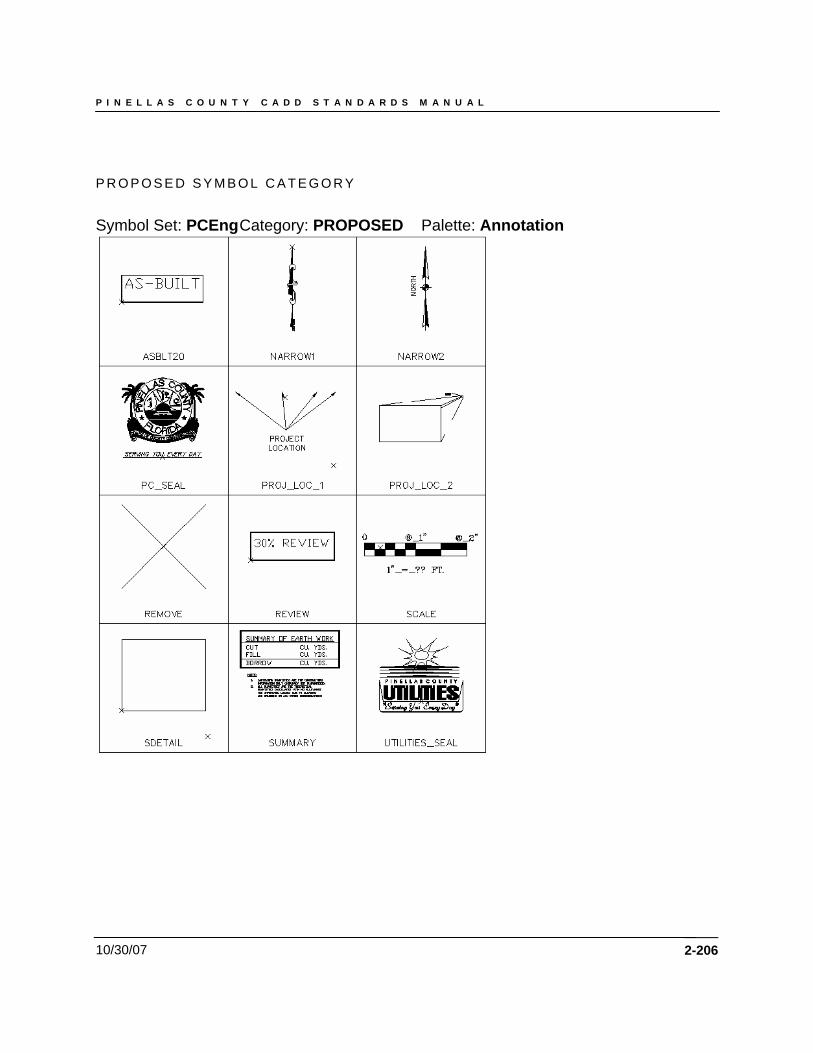
P I N E L L A S C O U N T Y C A D D S T A N D A R D S M A N U A L
10/30/07
P R O P O S E D S Y M B O L C A T E G O R Y
Symbol Set: PCEng Category: PROPOSED Palette: Annotation
2-206
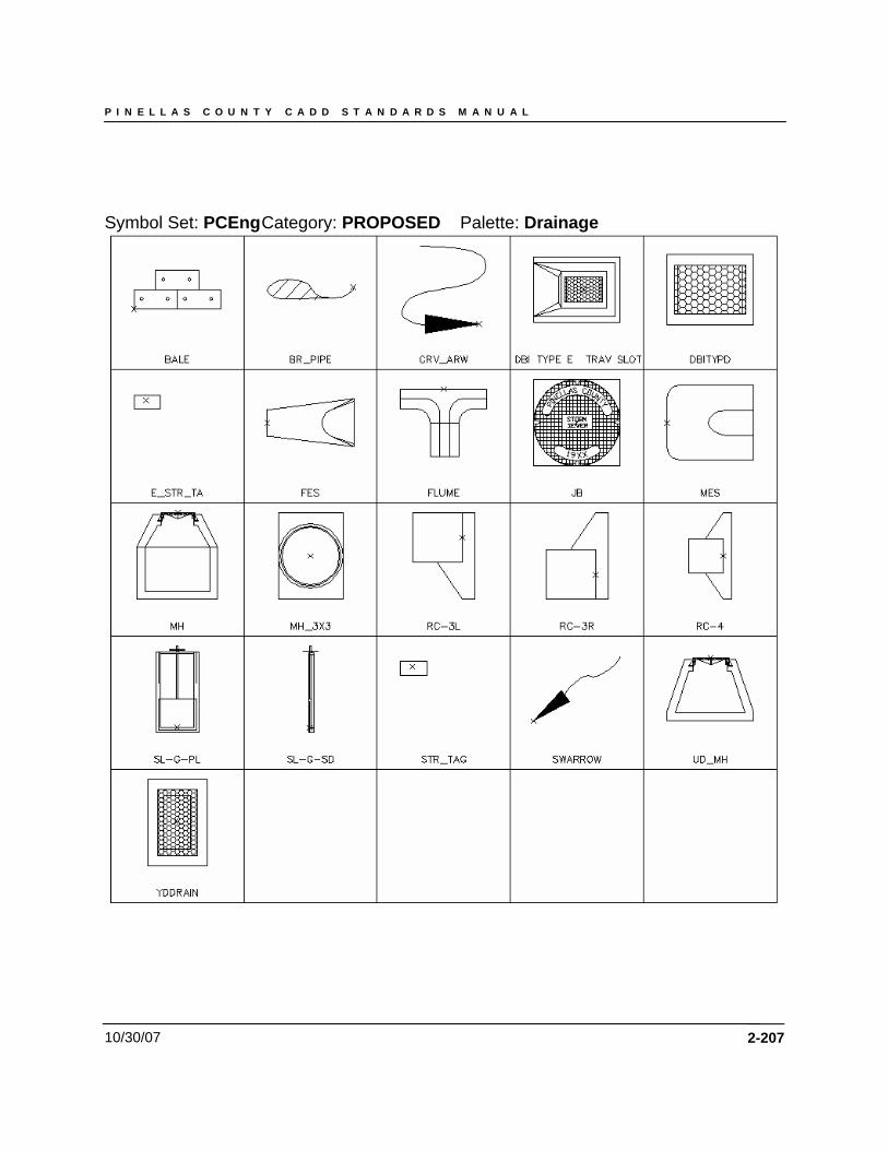
P I N E L L A S C O U N T Y C A D D S T A N D A R D S M A N U A L
10/30/07
Symbol Set: PCEng Category: PROPOSED Palette: Drainage
2-207
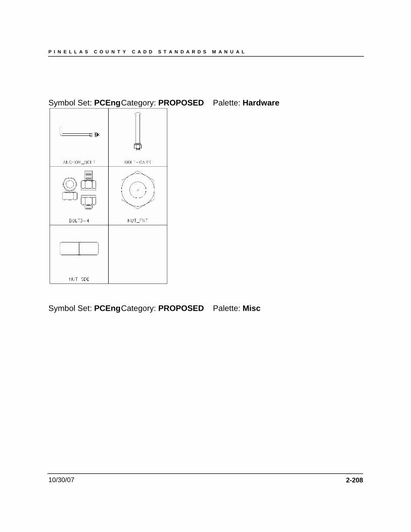
P I N E L L A S C O U N T Y C A D D S T A N D A R D S M A N U A L
10/30/07
Symbol Set: PCEng Category: PROPOSED Palette: Hardware
Symbol Set: PCEng Category: PROPOSED Palette: Misc
2-208
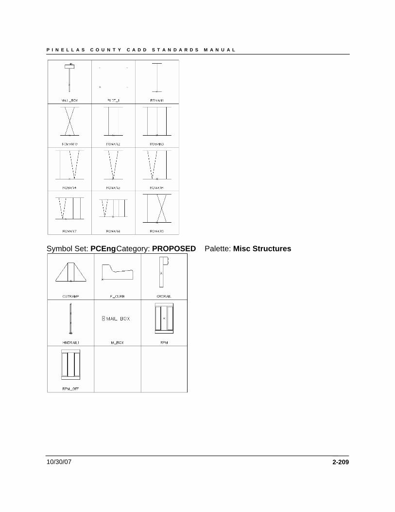
P I N E L L A S C O U N T Y C A D D S T A N D A R D S M A N U A L
10/30/07
Symbol Set: PCEng Category: PROPOSED Palette: Misc Structures
2-209

P I N E L L A S C O U N T Y C A D D S T A N D A R D S M A N U A L
10/30/07 2-210
Symbol Set: PCEng Category: PROPOSED Palette: Survey
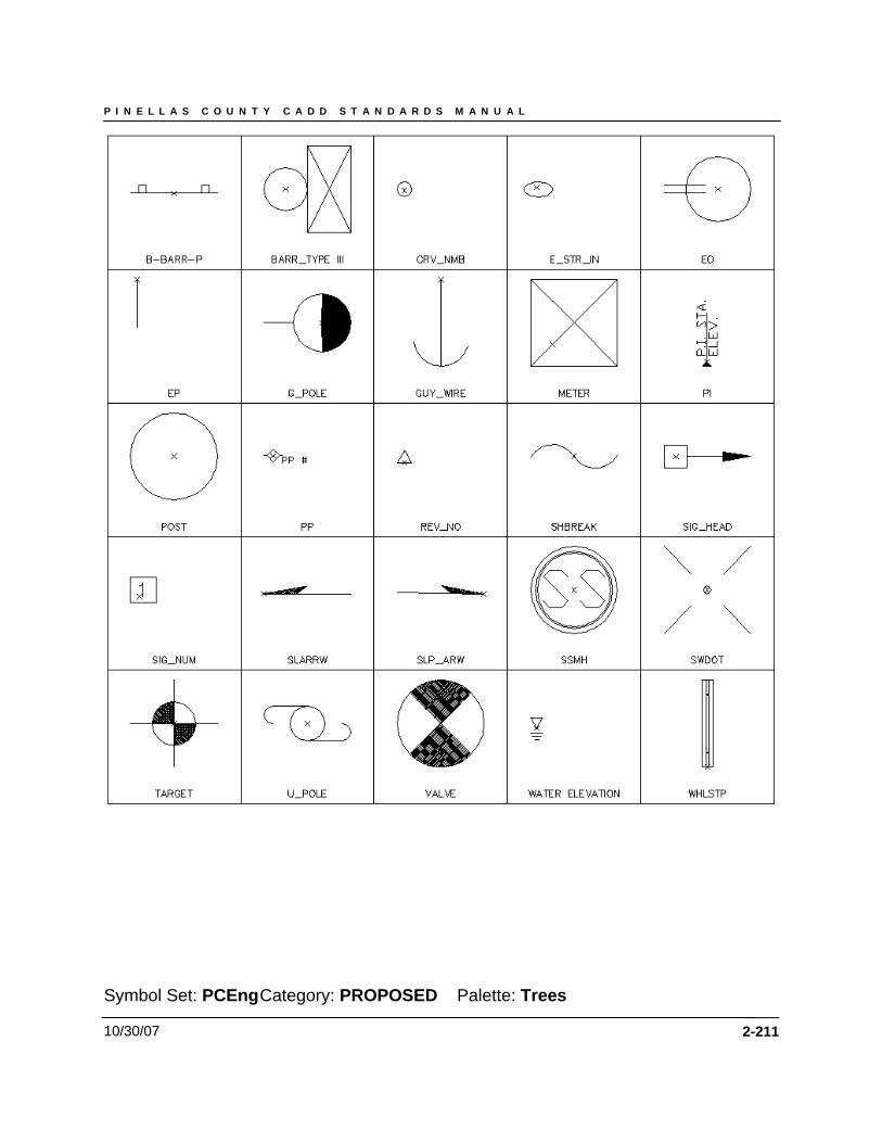
P I N E L L A S C O U N T Y C A D D S T A N D A R D S M A N U A L
10/30/07
Symbol Set: PCEng Category: PROPOSED Palette: Trees
2-211
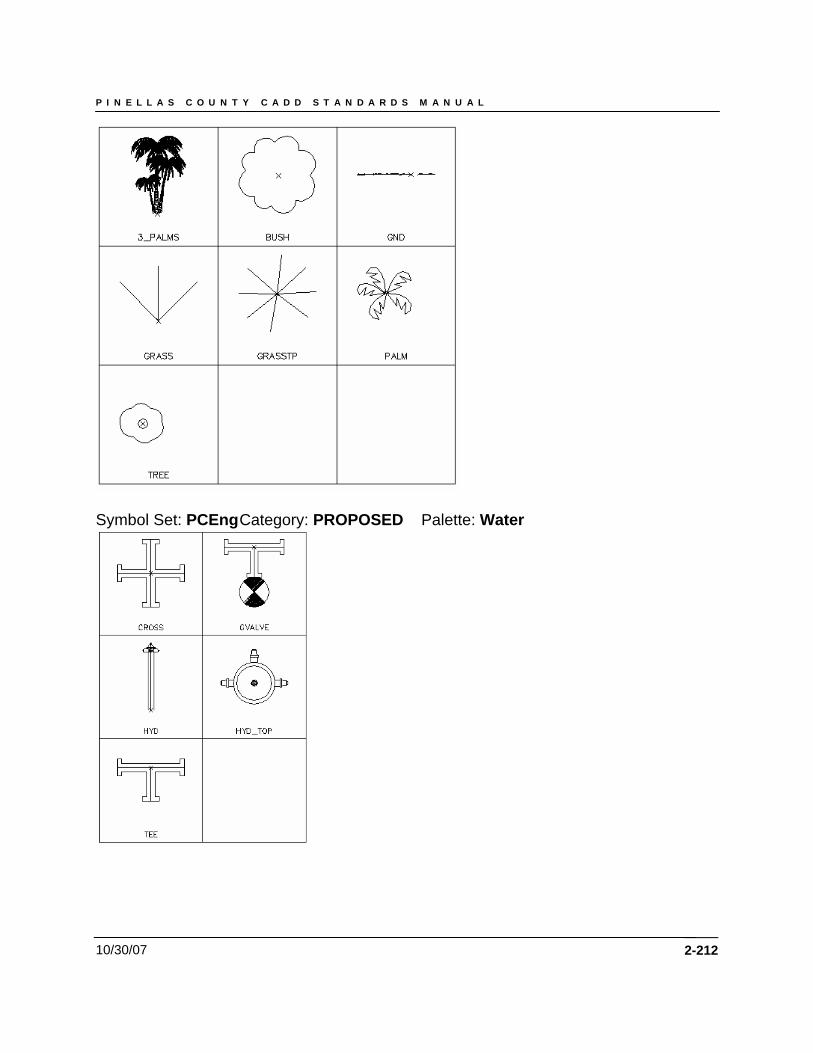
P I N E L L A S C O U N T Y C A D D S T A N D A R D S M A N U A L
10/30/07
Symbol Set: PCEng Category: PROPOSED Palette: Water
2-212
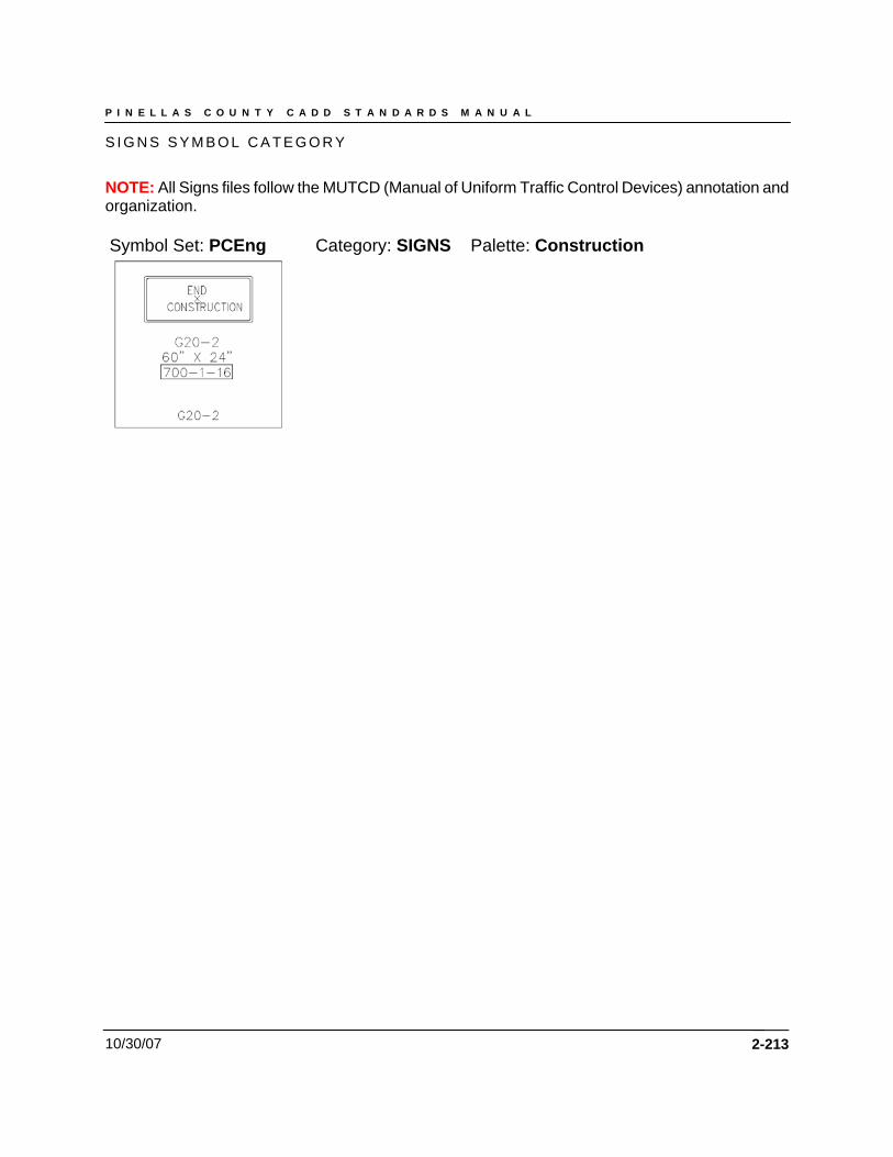
P I N E L L A S C O U N T Y C A D D S T A N D A R D S M A N U A L
10/30/07
S I G N S S Y M B O L C A T E G O R Y
NOTE: All Signs files follow the MUTCD (Manual of Uniform Traffic Control Devices) annotation and organization. Symbol Set: PCEng Category: SIGNS Palette: Construction
2-213
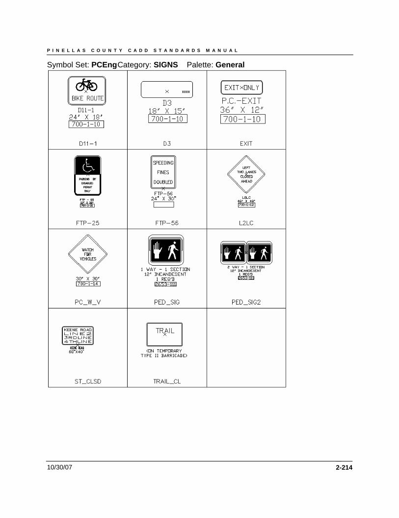
P I N E L L A S C O U N T Y C A D D S T A N D A R D S M A N U A L
10/30/07
Symbol Set: PCEng Category: SIGNS Palette: General
2-214
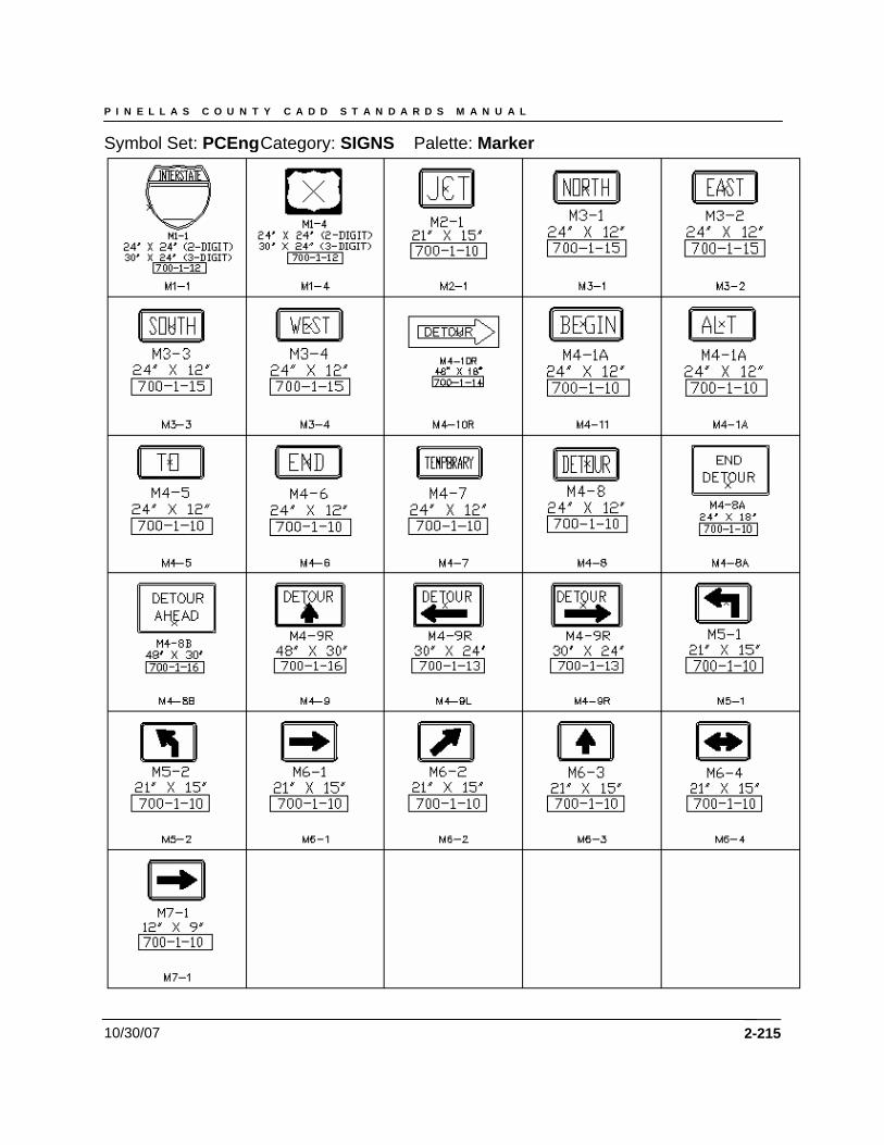
P I N E L L A S C O U N T Y C A D D S T A N D A R D S M A N U A L
10/30/07
Symbol Set: PCEng Category: SIGNS Palette: Marker
2-215
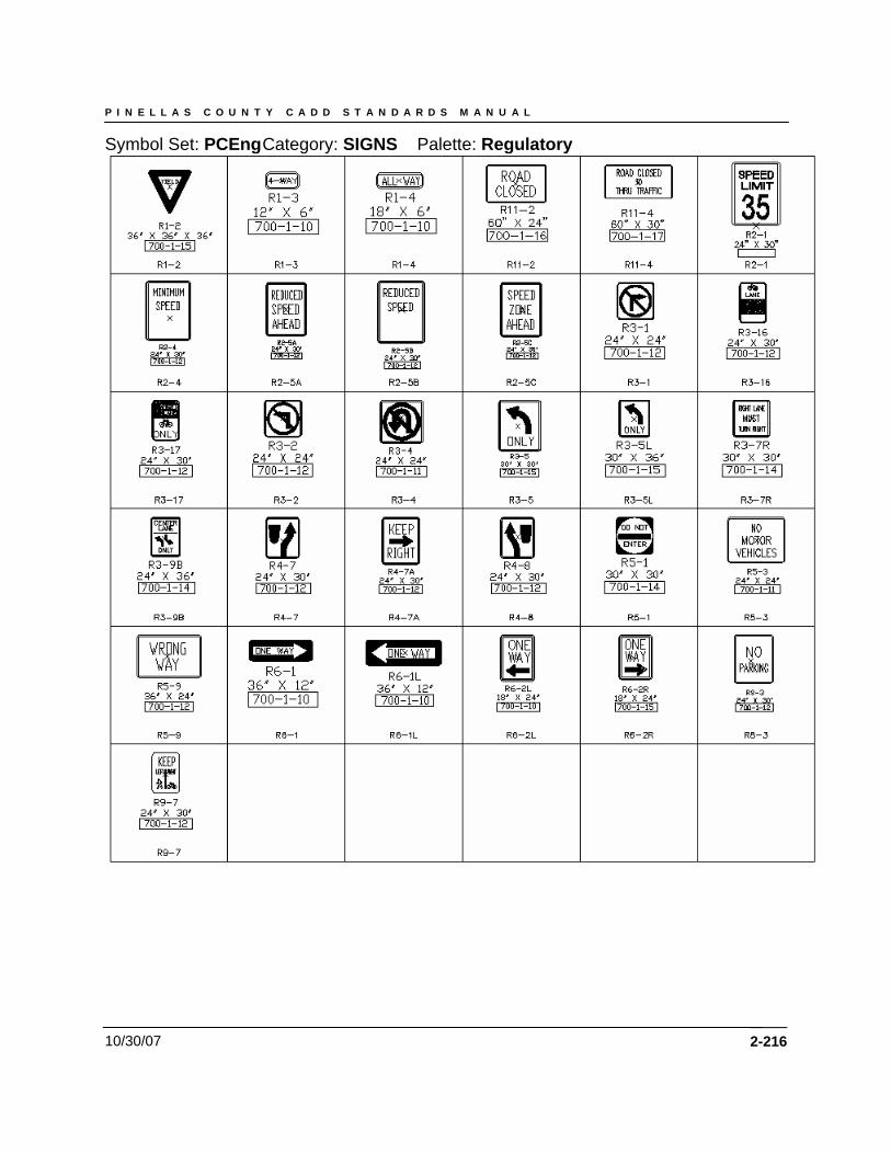
P I N E L L A S C O U N T Y C A D D S T A N D A R D S M A N U A L
10/30/07
Symbol Set: PCEng Category: SIGNS Palette: Regulatory
2-216
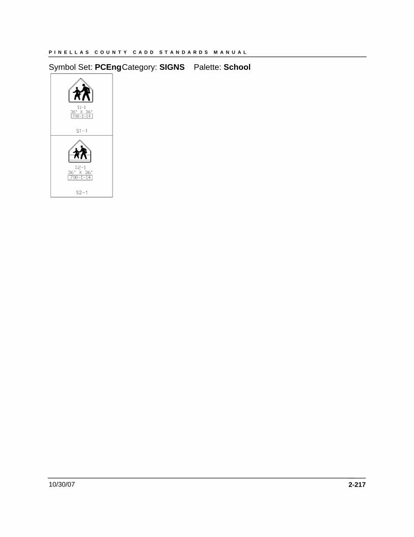
P I N E L L A S C O U N T Y C A D D S T A N D A R D S M A N U A L
10/30/07
Symbol Set: PCEng Category: SIGNS Palette: School
2-217
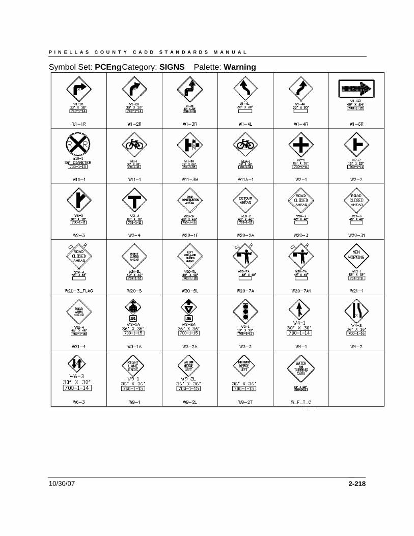
P I N E L L A S C O U N T Y C A D D S T A N D A R D S M A N U A L
10/30/07
Symbol Set: PCEng Category: SIGNS Palette: Warning
2-218
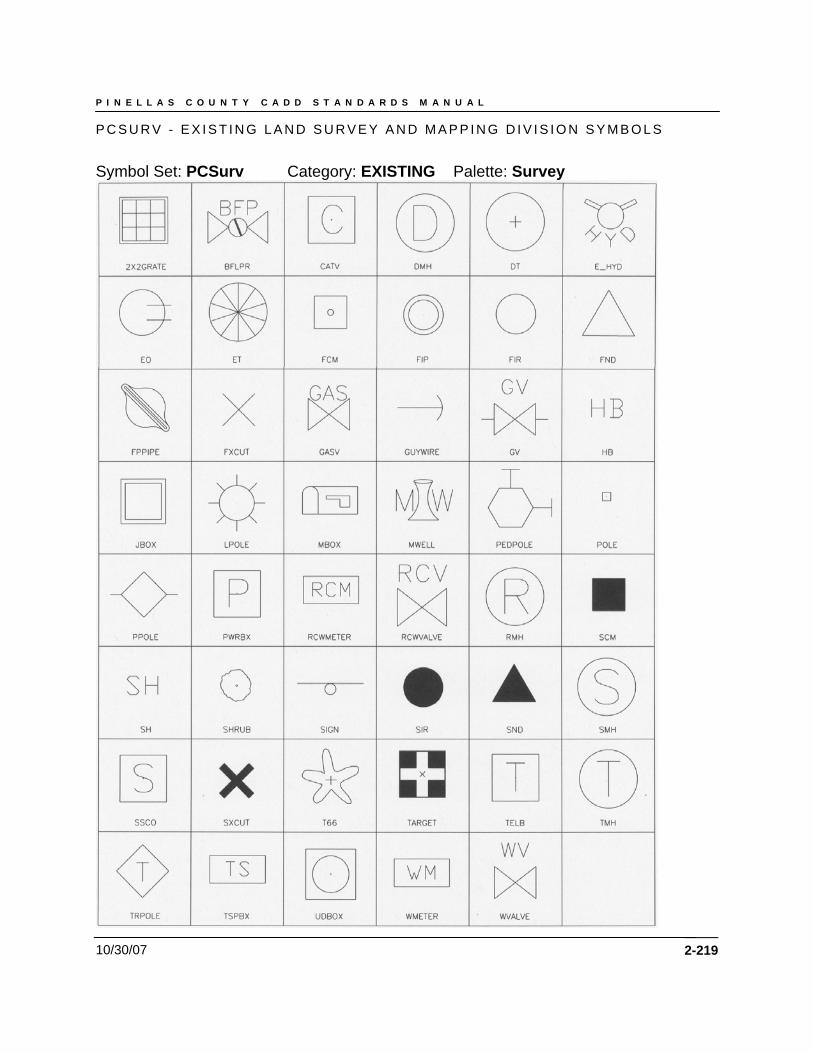
P I N E L L A S C O U N T Y C A D D S T A N D A R D S M A N U A L
10/30/07
P C S U R V - E X I S T I N G L A N D S U R V E Y A N D M A P P I N G D I V I S I O N S Y M B O L S
Symbol Set: PCSurv Category: EXISTING Palette: Survey
2-219
P I N E L L A S C O U N T Y C A D D S T A N D A R D S M A N U A L
10/30/07 2-220
Drawing Examples Cover Sheet General Notes and Legend Symbology and Linetype Quantities Control Point Coordinates / Monumentation Typical Section Survey Base Map Existing Structures / Demolitions Plan Alignments – Land Survey Reference Drainage Map Plan Plan & Profiles DTM / DEM / Grading Models Storm Drainage Map Utility Plan (WM, SS, FM & RCWM) Private – Utilities (SUE) Structures Cross Sections Mitigation Erosion / Turbidity Control Environmental NPDES Permitting Plan Geo Technical Maintenance of Traffic (MOT) Signing & Marking Plan Landscaping Plan Details