piko a-track h0 track system -...
TRANSCRIPT

PIKO A-TRACKH0 TRACK SYSTEM
9955
6/E
©20
12PI
KO
Subject to variations in colour and technical processing, errorsand availability for delivery.Measurements and illustrations may be subject to alteration.
G940 Flexible track, 940 mm (37”)G239 Straight track, 239 mm (9.41”)G231 Straight track, 231 mm (9.09”)G119 Straight track, 119 mm (4.71”),
2 x G119 make up the length of thestraight track G239.
G115 Straight track, 115 mm (4.55”),2 x G115 make up the length of thestraight track G231.
G107 Straight track, 107 mm (4.23”),parallel track for the 30° crossing K30
G62 Straight track, 62 mm (2.44”),Adaptor track from R3 and R4
R1 Curved track R1, r = 360 mm (14.17”)R2 Curved track R2, r = 422 mm (16.61”)R3 Curved track R3, r = 484 mm (19.05”)R4 Curved track R4, r = 546 mm (21.48”)R9 Curved track for switch R9,
r = 908 mm (35.75”)
R1 7,5 Curved track 7,5°, r = 360 mm 14.17”)R2 7,5 Curved track 7,5, r = 422 mm (16.61”)
K15 Crossing K15, 15° angleK30 Crossing K15, 30° angle
BWL Left hand curved switchBWR Right hand curved switch
BWL-R3 Left hand curved switch R3 to R4BWR-R3 Right hand curved switch R3 to R4
WL Left hand switchWR Right hand switch
W3 3-Wegeweiche
WY Y Switch
DKW Double Slip Switch
PIKO A-TRACK H0 TRACK SYSTEM
PIKO Spielwaren GmbHLutherstraße 30 · 96515 Sonneberg, GermanyFax: +49 36 75 89 72 50 · e-mail: [email protected]

3The 470 mm Module - The Starting Point The basisof the tracks design is the 470 mm by 61.88 mm(18.5” by 2.44”) unit. These measurements are notaccidental; they are the result of intensive studiescarried out with the help of high quality CADprograms to meet the requirements of bothamateurs and model train enthusiasts.
With this system almost any track design can beconstructed with no need for extra shorter pieces:elegant turnouts, straight or curved, variouscrossovers from one parallel track to the other, andthe opportunity to add accessories such asplatforms, etc.
This simple system makes complicated designcharts superfluous. The layouts can be sketched ona sheet of ordinary squared paper to establishwhich particular pieces are required.
The Track Design The outstanding feature of thePIKO A-Track is the small number of differentpieces. The modeller doesn’t have to installadditional pieces at either switches or crossings,which when used nearly always lead to unevenrunning.
The 470 mm (18.5”) module is divided into twostraight tracks of 231 mm (9.09”) and 239 mm(9.41”). This is the reason why you can have twoparallel tracks with two turnouts with no need foradditional pieces.
The Track The PIKO A-Track is made from a highquality nickel silver alloy and has good electricalconductibility even on long sections of track. Railjoiners ensure constant power, and guaranteegood electrical conductibility at the joints in therails.
The sleepers are made of high quality ABSmaterial, characterised by its high impactresistance, noise reduction and a resistance tocracking under stress.
As in the prototype, the surface of the sleepers ismade to look like wood and the spacing betweensleepers is to scale. This makes it look realisticwithout being over-crowded.
The Track Identification The PIKO A-Track has bothan article number and a second reference thatidentifies its type and size, for example 55201 andG231. G signifies straight and 231 is the length inmm. This second identification is used in the trackdiagrams. In addition to this, each type of trackhas its own colour, which is also used in thebrochures and catalogues and on the boxes. Allthis makes it easy to recognise which piece of trackis needed.
THE SECRET IS THE SYSTEM: PIKO A-TRACK
Clear and simple design that requires only a small range of trackpieces to construct a complete layout
Realistic appearance with carefully crafted wooden sleepers
Solid non-corrosive nickel silver track with a high electricconductibility
Limitless opportunities for layout expansion, because the trackpieces are compatible with those of all other manufacturers of H0scale DC track systems
PIKO A-Track HO Track System
The basic surface of 470 mm (18.5”) to 61.88 mm (2.44”) for thePIKO A-Track design is the result of intensive studies carried outon high quality CAD programs.
54Straight Track The PIKO A-Track normally requiresonly two straight tracks: G239 and G231. Joinedtogether they form the 470 mm (18.5”) module.Other straight tracks such as G115 and G119 can beused at will but are only necessary whenconstructing complex layouts.
The straight track G107 is only needed as a paralleltrack for 30° crossings.
For curved switches leading from radius R3(483.8 mm, 19.05”) to R4 (545.6 mm, 21.48”) youneed the straight track G62, which correspondsprecisely in length to the distance between thetwo curves of 61.88 mm (2.44”).
Flexible Track Sometimes modellers want to createa track layout in a particularly attractive landscapewhich in no way conforms to a simple geometriclayout. Here the flexible 940 mm PIKO A-Trackcomes into its own. Its length is equal to two470 mm (18.5”) modules. The flexible track G940can be bent to a much smaller radius than R1 (360mm, 14.17”). A radius of less than 358 mm (14.09”)may lead to the derailing of larger locomotivesand rolling stock. If a modeller wishes to set aradius smaller than 358 mm (14.09”) it is advisableto test the train beforehand.
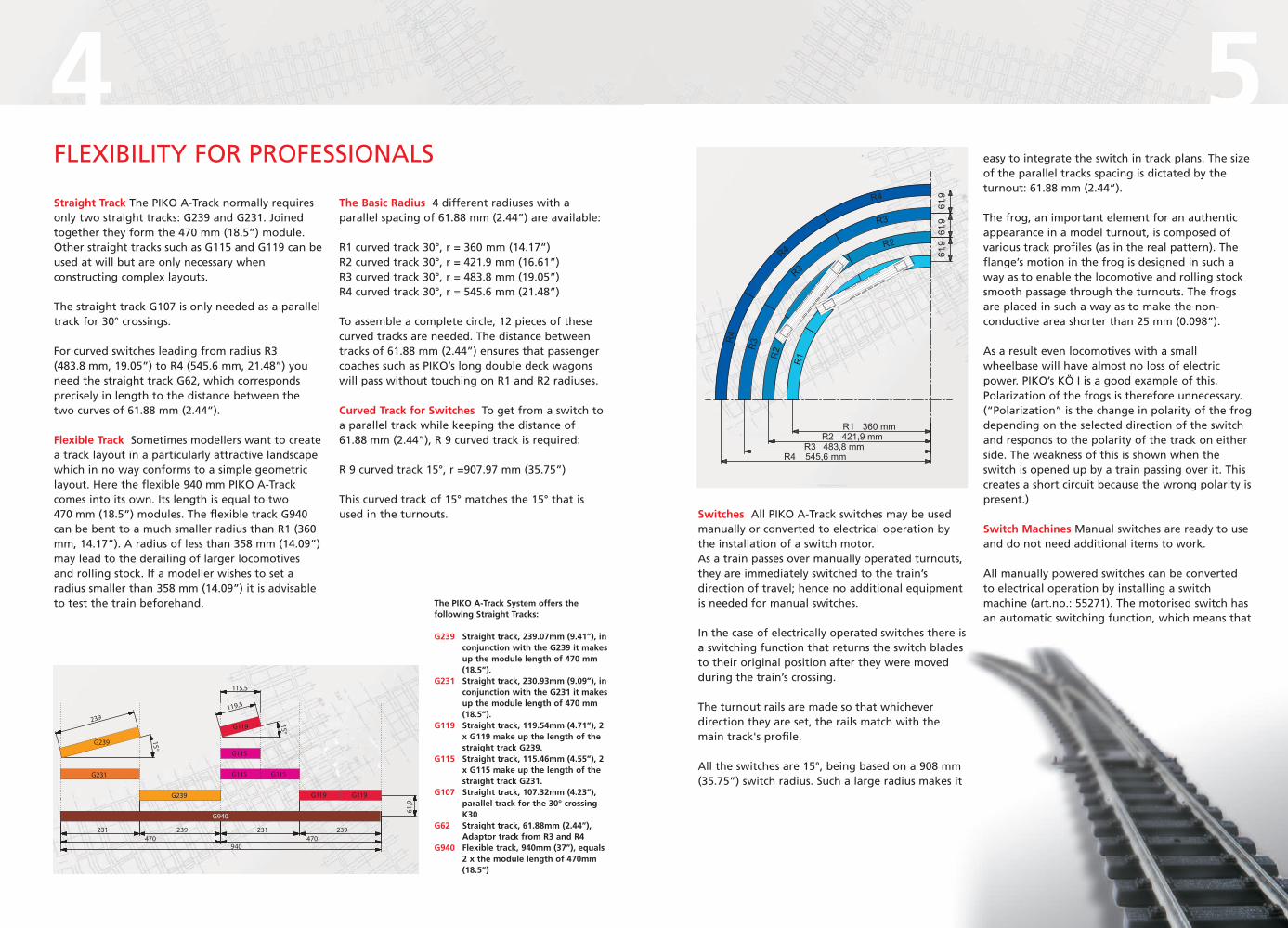
The Basic Radius 4 different radiuses with aparallel spacing of 61.88 mm (2.44”) are available:
R1 curved track 30°, r = 360 mm (14.17”)R2 curved track 30°, r = 421.9 mm (16.61”)R3 curved track 30°, r = 483.8 mm (19.05”)R4 curved track 30°, r = 545.6 mm (21.48”)
To assemble a complete circle, 12 pieces of thesecurved tracks are needed. The distance betweentracks of 61.88 mm (2.44”) ensures that passengercoaches such as PIKO’s long double deck wagonswill pass without touching on R1 and R2 radiuses.
Curved Track for Switches To get from a switch toa parallel track while keeping the distance of61.88 mm (2.44”), R 9 curved track is required:
R 9 curved track 15°, r =907.97 mm (35.75”)
This curved track of 15° matches the 15° that isused in the turnouts. Switches All PIKO A-Track switches may be used
manually or converted to electrical operation bythe installation of a switch motor.As a train passes over manually operated turnouts,they are immediately switched to the train’sdirection of travel; hence no additional equipmentis needed for manual switches.
In the case of electrically operated switches there isa switching function that returns the switch bladesto their original position after they were movedduring the train’s crossing.
The turnout rails are made so that whicheverdirection they are set, the rails match with themain track's profile.
All the switches are 15°, being based on a 908 mm(35.75”) switch radius. Such a large radius makes it
easy to integrate the switch in track plans. The sizeof the parallel tracks spacing is dictated by theturnout: 61.88 mm (2.44”).
The frog, an important element for an authenticappearance in a model turnout, is composed ofvarious track profiles (as in the real pattern). Theflange’s motion in the frog is designed in such away as to enable the locomotive and rolling stocksmooth passage through the turnouts. The frogsare placed in such a way as to make the non-conductive area shorter than 25 mm (0.098”).
As a result even locomotives with a smallwheelbase will have almost no loss of electricpower. PIKO’s KÖ I is a good example of this.Polarization of the frogs is therefore unnecessary.(“Polarization” is the change in polarity of the frogdepending on the selected direction of the switchand responds to the polarity of the track on eitherside. The weakness of this is shown when theswitch is opened up by a train passing over it. Thiscreates a short circuit because the wrong polarity ispresent.)
Switch Machines Manual switches are ready to useand do not need additional items to work.
All manually powered switches can be convertedto electrical operation by installing a switchmachine (art.no.: 55271). The motorised switch hasan automatic switching function, which means that
The PIKO A-Track System offers thefollowing Straight Tracks:
G239 Straight track, 239.07mm (9.41”), inconjunction with the G239 it makesup the module length of 470 mm(18.5”).
G231 Straight track, 230.93mm (9.09”), inconjunction with the G231 it makesup the module length of 470 mm(18.5”).
G119 Straight track, 119.54mm (4.71”), 2x G119 make up the length of thestraight track G239.
G115 Straight track, 115.46mm (4.55”), 2x G115 make up the length of thestraight track G231.
G107 Straight track, 107.32mm (4.23”),parallel track for the 30° crossingK30
G62 Straight track, 61.88mm (2.44”),Adaptor track from R3 and R4
G940 Flexible track, 940mm (37”), equals2 x the module length of 470mm(18.5”)
FLEXIBILITY FOR PROFESSIONALS

76after the passing of the train, the switch is movedback to its original position. Electric switches canalso be operated manually.
The switch machine is attached to the switch byspecial connections. Owing to its narrow shape itcan also be fitted onto switches that are very closetogether. If the track design does not leaveenough space, as in a junction on the curve passingfrom radius R3 to R2, the motor may be installedunderneath. For this an underfloor installation kitis required (art.no.: 55273).
The switches may be operated by othermanufacturers' below the baseboard motors, asthere is an appropriate hole in the tie, at whichthe switch direction is set.
Wheels and Track The solid rail is made out ofnickel silver, is non-corrosive and characterised byhigh electrical conductivity.
The PIKO rails are 2.5 mm (0.098”) high (code 100),and therefore correspond to the NEM norm 120.This means you can use the PIKO track for almostall stock with traditional wheel profiles made byother producers.
The small metal parts, which in the prototype holdthe rails onto the sleepers, are accuratelyreproduced so that all standard wheel types cantravel freely over all the pieces of the PIKO A-Trackwithout rattling.
Laying the track Thanks to the high quality railjoiners made of sprung steel, the PIKO A-Track canbe used on every type of surface, including a shortpile house carpet.
However in order to prolong the life of yourmodel railway, we recommend fixing the tracks toa wooden baseboard with PIKO track screws(art.no.: 55298). This will stop the track beingmoved by centrifugal force when running fast orheavy trains. Each track piece is made with theholes required for the unobtrusive screws.
Power Connection The easiest way of providingthe PIKO A-Track with an electrical connection is byusing the power connector (art.no.: 55270). It canbe fitted to each straight track G231 (and no otherpieces). The wires supplied with the control unitcan then be used to connect to the power supply.
If the modeller wants to install track withelectrically isolated sections, or wants to supplyparticular parts of the track with power, he can usespecial rail joiners with connecting wires (art.no.:55292). These rail joiners should be used instead ofthe existing ones on each track.
Geometric Examples:1 Transition from one track to parallel tracks2 Transition from one track to parallel tracks with “platform”
spacing3 Transition from one track to parallel tracks with double
spacing4 Transition from one track to three parallel tracks5 Transition from a parallel track to three parallel tracks
FROM ONE TRACK TO THE NEXT
1 4
2 5
3 6
7
8
6 Transition from a parallel track with “platform” spacing to twoparallel tracks and one parallel track with “platform” spacing
7 A complex layout with parallel tracks and crossings8 Transition from a parallel track into a station layout with
alternate parallel tracks and a parallel tracks with “platform”spacing
The scale-built rail profiles 2.5 mm in height ensure the passageof vehicles with conventional wheelsets made by differentmanufacturers.

98Rail Joiners All the rail joiners are made of non-corrossive sprung steel and not only guarantee along life and good contacts, but simultaneouslyensure a constant current in the track.For special purposes rail joiners with wiresattached are used (art.no.: 55292).
In order to separate parts of the tracks electrically,insulated rail joiners must be used (art.no.: 55291).These simply replace the existing rail joiners.
In order to ensure smooth passage between thePIKO A-Track and the very old PIKO U-Profile trackproduced up to the year 1990, the transition trackGUE62 H art.no.: 55207) should be used. It is thesame size as the straight track G62, but has ashaped profile at one end that fits perfectly intothe hollow profile of the old PIKO U-Profile track.This makes it easy to set up permanent electricalconnections to older PIKO layouts.
Easy connection to other manufacturers' tracks (seealso the description of the adaptor track GUE62-U)is possible if they offer 2.5 mm (0.098”) rail profilesand rails with no permanently attached track bedsor ballast. In such a case combining the PIKO A-Track with other manufacturers' track profiles isachieved by using the PIKO A-Track rail joiners
with two different end widths (art.no.: 55293).These are indispensable, as most manufacturersoffer much wider rail profiles.
The adaptor track GUE62-U (art.no.: 55208) is thesame length as straight track G32 and may be usedinstead of rail joiners 55293. This adaptor trackalready has the rail joiners attached with thedifferent end widths, which you need to connectto other manufacturers' tracks.
For tracks with permanently attached track beds orballast, the manufacturers normally offer their
own adaptor pieces, which ensure an almostentirely smooth connection to the 2.5 mm (0.098”)PIKO A-Track corresponding to the NEM 120 norm.Because of the differences in the rail profile width,PIKO rail joiners with two different end widths55293, or the adaptor track GUE-62U should beadditionally installed.
For joining the PIKO A-Track to othermanufacturers' track of 2,1mm (0.083”) height, railjoiners offsetting the difference of levels betweenthe profiles should be used.In these cases, rail joiners art.no.: 55294) should beused instead of the joiners fitted as standard tomake this connection.
Rail joiners with twodifferent end widths
Rail joiners with twodifferent end widths
Tracks of othermanufacturers witha wider rail profileand a profile heightof 2,5mm (0.098”)
PIKO A-Trackprofile height2,5mm(0.098”)
1 2 3 4
5 6
7 8 9 10
11 12 13
Geometric Examples for Curved Track:1 Transition from radius R3 to R2 and R32 Transition from radius R2 to R2 and R33 Transition from the parallel radius R2 to R2 and R34 Transition from the parallel radius R3 to R2 and R35 Transition from the parallel radius R3 to R2, R3 and R46 Transition from the parallel radiuses R4 to R3 and R4
and from R2 to R2 and R37 Transition from radius R4 to R3 and R48 Transition from radius R3 to R3 and R49 Transition from the parallel radius R3 to R3 and R4
10 Transition from the parallel radius R4 to R3 and R411 Transition from the parallel radiuses R4 to R3, R4 and R5
12 Transition from the parallel radiuses R5 to R4 and R5 andfrom R3 to R3 and R4
13 Transition from the parallel radiuses R5 to R4 and R5,and from R3 to R3 and R4 and from R2 to R2 and R3
Note: Crossing over to a radius R1 curve using these curvedswitches is not possible because our curved switches have a basicradius of 421.9 mm (16.61”) (= R2). To cross over to the radius R1curve we would have had to choose a basic radius of 360 mm(14.17”) (= R1) for our turnouts. Since for technical reasons notevery locomotive can run through this radius of switch, thiswould not have been acceptable..
R5: There are no turned tracks for the radius R5.
55240 Crossing K15Crossing K15, 15° angle, straight track = G239
55241 Crossing K30Crossing K30, 30° angle, straight track = G119
55224 Double Slip Switch DKWDouble slip switch, 15° angle, straight track =G239, turnouts = R9. Manually operated withpositioning, switch machines = 2 x # 55271
55225 Three Way Switch W3Three way switch, 2 x 15° angle, straight track =G239, turnouts = R9. Manually operated withpositioning, switch machines = 2 x # 55271
Straight and Flexible Track
55209 Flexible Track 940 mm (37”)Flexible track, 940 mm long that corresponds todouble the length of the module 470 mm (18.5”)
55200 Straight Track 239 mm (9.41”)Straight track G239, 239.07 mm long, G239 + G231make up a module of 470 mm (18.5”) long.
55201 Straight Track 231 mm (9.09”)Straight track G231, 230.93 mm long, G231 + G239make up a module 470 mm (18.5”) long.
55202 Straight Track 119 mm (4.71”)Straight track G119, 119.54 mm long2 x G119 equals G239
55203 Straight Track 115 mm (4.55”)Straight track G115, 115.46 mm long2 x G115 equals G231
55204 Straight Track 107 mm (4.23”)Straight track G107, 107.32 mm long, parallel trackfor the 30° crossing K30
55205 Straight Track 62 mm (2.44”)Straight track G62, 61.88 mm long, adaptor trackfrom R3 and R4
55207 Adaptor Track 62 mm (2.44”)Adaptor track GUE62-H fits between the PIKO A-Track and the old U-Profile track 61.88 mm long.
55208 Adaptor Track 62 mm (2.44”)Adaptor track GUE62-U fits between the PIKO A-Track and the PIKO-Hobby track, produced from1992 to 2000, the Mehano* track, the classicROCO* 2.5 mm (0.098”) brass and nickel track, theFleischmann* Profi- and Model tracks as well asothers with a 2.5 mm (0.098”) profile height.61.88 mm long.
1055282 Sleepers 31 mm for Flex TrackThese sleepers (not complete tracks) can beattached to the flex track to achieve a perfectconnection between flex track and the followingregular tracks.
Switches and Crossings
55220 55220 WL SwitchLeft hand switch, 15° angle, straight track = G239Turnout = R9, manually operated with positioning,switch machine = # 55271
55221 WR SwitchRight hand switch, 15° angle, straight track = G239Turnout= R9, manually operated with positioning,switch machine = # 55271
55222 Curved Switch BWLLeft hand curved switch. Suitable for passing fromradius R2 to R3 or R3 to R4, the main track’s radiusof the turnout is R2. Manually operated withpositioning, switch machine = # 55271
55227 Curved Switch BWL-R3, leftLeft hand curved switch. Suitable for passing fromradius R3 to R4, the main track’s radius of theturnou R3. Manually operated with positioning,switch machine = # 55271
55223 Curved Switch BWRRight hand curved switch. Suitable for passingfrom radius R2 to R3 or R3 to R4, the main track’sradius of the turnout is R2. Manually operatedwith positioning, switch machine = # 55271
55228 Curved Switch BWR-R3, rightRight hand curved switch. Suitable for passingfrom radius R3 to R4, the main track’s radius ofthe turnout is R3. Manually operated withpositioning, switch machine = # 55271
TRACK - FOR INDIVIDUALISTS
55226 Y Switch WYY switch, 30° angle, turnouts = R9, manuallyoperated with positioning, switch machines =2 x # 55271
Curved Track
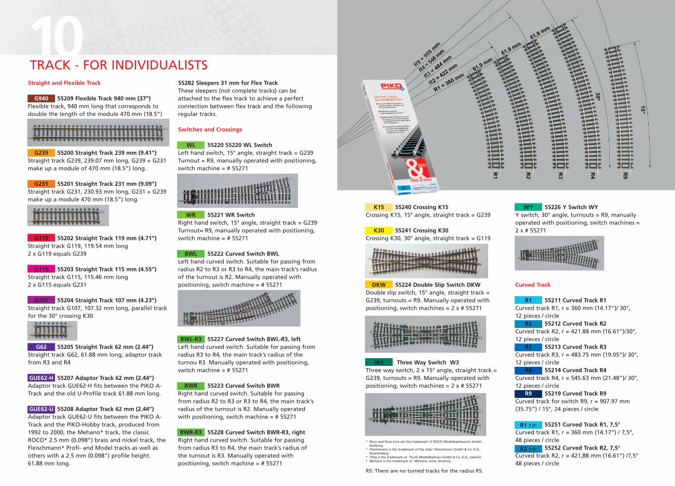
55211 Curved Track R1Curved track R1, r = 360 mm (14.17”)/ 30°,12 pieces / circle
55212 Curved Track R2Curved track R2, r = 421.88 mm (16.61”)/30°,12 pieces / circle
55213 Curved Track R3Curved track R3, r = 483.75 mm (19.05”)/ 30°,12 pieces / circle
55214 Curved Track R4Curved track R4, r = 545.63 mm (21.48”)/ 30°,12 pieces / circle
55219 Curved Track R9Curved track for switch R9, r = 907.97 mm(35.75”) / 15°, 24 pieces / circle
55251 Curved Track R1, 7,5°Curved track R1, r = 360 mm (14.17”) / 7,5°,48 pieces / circle
55252 Curved Track R2, 7,5°Curved track R2, r = 421,88 mm (16.61”) /7,5°48 pieces / circle
G940
G239
G231
G119
G115
G107
G62
GUE62-H
GUE62-U
WL
WR
BWL
BWR
K15
K30
DKW
W3
WY
R1
R2
R3
R4
R9
* Roco and Roco-Line are the trademark of ROCO–Modellspielwaren GmbH ,Salzburg.
* Fleischmann is the trademark of the Gebr. Fleischmann GmbH & Co. K.G.,Nueremberg
* Tillig is the trademark of TILLIG Modellbahnen GmbH & Co. K.G., Sebnitz* Mehano is the trademark of Mehano, Izola, Slovenia .
BWR-R3
BWL-R3
R1 7,5°
R2 7,5°
R5: There are no turned tracks for the radius R5.

12ACCESSORIES – FOR EXPERTS
* Roco are the trademark of Modelleisenbahn GmbH, Bergheim* Fleischmann is the trademark of the Gebr. Fleischmann GmbH & Co. K.G., Nuremberg.* Tillig is the trademark of TILLIG Modellbahnen GmbH & Co. K.G., Sebnitz* Mehano is the trademark of Mehano, Izola, Slovenia.
55270 Power Connection (Terminal Box)Terminal box with suppressor fits to track G231.
55273 Underfloor Installation Kit for Switch MachineThis kit is required if you plan to install the switchmachine # 55271 underneath the switch.
55293 Rail Joiners with Two End Widths, 6 piecesRail joiners made of sprung steel with two differentend widths, make connection possible to the PIKO-Hobby track produced between 1992 and 2002, theMehano* track, classic Roco* 2.5 mm (0.098”) track ofbrass and nickel, the Fleischmann Profi* – and modeltracks and other tracks with 2.5 mm (0.098”) highprofiles, 6 pieces.
55281 TrackCleaning Block
55271 Switch Machine Right/LeftMotor for all switches, low electric powerconsumption.
55280 Bumper (Buffer Stop)Buffer Stop of wooden appearance, can be clippedor screwed onto all straight tracks.
55297 Phillips Screwdriver for PIKO A-TrackThis electronic Phillips screwdriver has the followinginnovative properties:- Designed for maximum handling comfort.- The ergonomically designed top revolves smoothly.- Hardened steel blade with ergonomic designed
handle for faster, more powerful, and less tiringscrewdriving action.
- With blackpoint.- A special precision zone ensures precise working.
55299 Track Nails, about400 pieces
55292 Rail Joiners withConnecting Wires, 1 pairSprung steel rail joiners withconnecting wires, 1 pair
55290 Rail Joiners 24 pieces
55294 Rail Joiners for Different Heights, 6 piecesRail joiners for different heights, to equalize thedifferent levels when passing from ROCO*-Line andTillig*- Elite to PIKO A-Track, 6 pieces
55261 SwitchboardFor changing switches and signalsthat are electrically operated
55262 SwitchboardFor changing switches and signalsthat are electrically operated
55298 Track Screws, about400 pieces
55296 Track-nail holder & hammer
55275 Power Clip for Digital SystemsThis power clip without an EMV interferencesuppressor is essential for digital systems. The clipperfectly plugs into track G231.
55392 Set of Switch MachinesThis set includes 1 switchboard 55260 for changingswitches and signals that are electrically operatedand 4 motors for all switches, low electric powerconsumption.
55291 Insulated Rail Joiners 24, piecesInsulated plastic rail joiners, 24 pieces
13
55391 Terminal Loop SetWith this terminal loop train set, terminal loopsare no problem. Consists of insulating connectors,cables and mounting connectors. Not suited fordigital operation.

TRACK SETS – FOR ADVANCED MODELLERSThe PIKO A-Track sets have been designed to allow both beginners and experienced modellers using thePIKO A-Track system for the first time to build up a basic stock of tracks at a reasonable price. Theuncomplicated, clear design of the PIKO A-Track permits continuous expansion of existing track designs ineasy steps. The sets contain the pieces in the pictures shown in the stronger colours, which conformthroughout to the PIKO A-Track system colour coding.The switches included in all track and starter sets may be converted at any time into electric switches byinstalling a suitable switch machine.
55300 Track Set AAll the PIKO starter sets include the contents of track set A. This setis offered separately to make it easy for modellers to begin using thePIKO A-Track system with their existing engines and rolling stock.Contents: 2 x 55201 G231 (straight track 231 mm), 12 x 55212 R2 (thecurved track R2 422 mm), 1 x 55270 terminal boxFloor area* A: 110 x 88 cm (43.3” x 34.7”)Minimum area for assembly: 120 x 98 cm (47.2” x 38.6”)
55310 Track Set BAn oval is the start of most track layouts. A switch and a siding giveadditional interest, making it possible to shunt the wagons, which iseven more fun.Contents: 1 x 55221 WR (right hand switch), 1 x 55200 G239 (straighttrack 239 mm) 5 x 55201 G231 (straight track 231 mm), 1 x 55280buffer stopFloor area* A + B: 158 x 88 cm (62.2” x 34.7”)Minimum area for assembly: 168 x 98 cm (66.2” x 38.6”)
*The suggested floor area is alwaysrounded up.
55330 Track Set D “The Freight Station”If track set D is added to the basic track set A, an interesting freightyard can be constructed. A number of sidings make space for parkingrolling stock that can be collected at different times by thelocomotive. Thus combining these sets provides plenty of scope forplaying.Contents: 9 x 55200 G239 (straight track 239 mm), 7 x 55201 G231(straight track 231 mm), 2 x 55219 R9 (curved track R9 908 mm), 3 x55220 WL (left hand switch), 2 x 55221 WR (right hand switch), 5 x55280 buffer stopFloor area* A + D: 205 x 88 cm (80.7” x 34.7”)Minimum area for assembly: 215 x 98 cm (84.7” x 38.6”)
55320 Track Set C “The Station Set”If the combination of sets A and B is extended by track set C, it’spossible to incorporate a station and operate two trains. This makesa really nice layout that may also be equipped with PIKO’s hobbybuildings.Contents:1 x 55200 G239 (straight track 239 mm), 1 x 55201 G231(straight track 231 mm), 1 x 55220 WL (left hand switch), 1 x 55221WR (right hand switch), 6 x 55211 R1 (curved track R1 360 mm), 2 x55219 R9 (curved track R9 908 mm)Floor area* A + B + C: 182 x 88 cm (71.7” x 34.7”)Minimum area for assembly: 192 x 88 cm (75.6” x 38.6”)
55340 Track Set E "Parallel Set"If track set E is added to the basic track set A, an interesting layoutcan be made with a by-pass track for parallelly running trains. This isespecially interesting for trains with lots of cars. Two trains can passeach other in front of a passenger station. The track set E offers agreat variety of laying out tracks in combination with the track sets Ato D.Contents: 3 x 55200 G239 (straight track 239 mm), 7 x 55201 G231(straight track 231 mm), 2 x 55212 R2 (curved track R2 422 mm), 1 x55222 BWL (curved left hand switch), 1 x 55223 BWR (curved righthand switch)Floor area* A + E: 182 x 95 cm (71.7” x 37.4”)Minimum area for assembly: 192 x 105 cm (75.6” x 41.3”)
1555230 Set of Screws forSwitch Machines (10 pieces)
55231 Set actuator springsfor Switch Machines (10 pieces)
5
5mm
5
5mm
14
55289 Rerail MechanismEases the process of setting locomotives andcars onto the tracks.