piezoelectric voltage coupled reentrant cavity...
TRANSCRIPT

Piezoelectric voltage coupled reentrant cavity resonatorCarvalho, N., Fan, Y., Le Floch, J-M., & Tobar, M. (2014). Piezoelectric voltage coupled reentrant cavityresonator. Review of Scientific Instruments, 85(10), [104705]. DOI: 10.1063/1.4897482
Published in:Review of Scientific Instruments
DOI:10.1063/1.4897482
Document VersionPublisher's PDF, also known as Version of record
Link to publication in the UWA Research Repository
Rights statementCopyright (2014) AIP Publishing. This article may be downloaded for personal use only. Any other userequires prior permission of the author and AIP Publishing.
The following article appeared in Review of Scientific Instruments 85, 104705 (2014); doi:10.1063/1.4897482 and may be found athttp://scitation.aip.org/content/aip/journal/rsi/85/10/10.1063/1.4897482.
General rightsCopyright owners retain the copyright for their material stored in the UWA Research Repository. The University grants no end-userrights beyond those which are provided by the Australian Copyright Act 1968. Users may make use of the material in the Repositoryproviding due attribution is given and the use is in accordance with the Copyright Act 1968.
Take down policyIf you believe this document infringes copyright, raise a complaint by contacting [email protected]. The document will beimmediately withdrawn from public access while the complaint is being investigated.
Download date: 22. Jun. 2018

Piezoelectric voltage coupled reentrant cavity resonatorN. C. Carvalho, Y. Fan, J-M. Le Floch, and M. E. Tobar Citation: Review of Scientific Instruments 85, 104705 (2014); doi: 10.1063/1.4897482 View online: http://dx.doi.org/10.1063/1.4897482 View Table of Contents: http://scitation.aip.org/content/aip/journal/rsi/85/10?ver=pdfcov Published by the AIP Publishing Articles you may be interested in Structural sensing of interior sound for active control of noise in structural-acoustic cavities J. Acoust. Soc. Am. 138, 11 (2015); 10.1121/1.4922235 A rotary piezoelectric actuator using longitudinal and bending hybrid transducer AIP Advances 2, 042136 (2012); 10.1063/1.4766676 Tuning limitations of the voltage-controlled planar microwave ferrite resonator J. Appl. Phys. 111, 07A506 (2012); 10.1063/1.3672397 Cavities with axially uniform fields for use in electron paramagnetic resonance. III. Re-entrant geometries Rev. Sci. Instrum. 73, 4003 (2002); 10.1063/1.1510549 Piezoelectrically actuated droplet ejector Rev. Sci. Instrum. 68, 4561 (1997); 10.1063/1.1148431
This article is copyrighted as indicated in the article. Reuse of AIP content is subject to the terms at: http://scitationnew.aip.org/termsconditions. Downloaded to IP:
130.95.83.49 On: Mon, 30 Nov 2015 08:48:56
REVIEW OF SCIENTIFIC INSTRUMENTS 85, 104705 (2014)
Piezoelectric voltage coupled reentrant cavity resonatorN. C. Carvalho,1,2,a) Y. Fan,1,2 J-M. Le Floch,1,2 and M. E. Tobar1,2
1School of Physics, The University of Western Australia, 35 Stirling Hwy, 6009 Crawley,Western Australia, Australia2ARC Centre of Excellence for Engineered Quantum Systems (EQuS), The University of Western Australia,35 Stirling Hwy, 6009 Crawley, Western Australia, Australia
(Received 30 May 2014; accepted 28 September 2014; published online 14 October 2014)
A piezoelectric voltage coupled microwave reentrant cavity has been developed. The central cavitypost is bonded to a piezoelectric actuator allowing the voltage control of small post displacementsover a high dynamic range. We show that such a cavity can be implemented as a voltage tunable res-onator, a transducer for exciting and measuring mechanical modes of the structure, and a transducerfor measuring comparative sensitivity of the piezoelectric material. Experiments were conducted atroom and cryogenic temperatures with results verified using Finite Element software. © 2014 AIPPublishing LLC. [http://dx.doi.org/10.1063/1.4897482]
I. INTRODUCTION
Microwave reentrant cavities are typically made up ofa right cylinder with a central post and have been widelyinvestigated.1–13 The post acts as a capacitor, creating avery intense electric field at the central region of the cav-ity, in the gap between the post and the adjacent wall.The magnetic field, on the other hand, circulates the post,composing the inductive region of the cavity.14 Adjust-ing the gap spacing between the post and the cavity’swall allows this cavity to be employed as a highly tun-able or displacement sensitive microwave resonator, mak-ing such a device very useful for a wide range of appli-cations, such as solid state microwave oscillators,15 particleaccelerators,16 dielectric characterization,17 electron spin res-onance spectroscopy,18 electromechanical transducers forgravitational wave detectors12, 19 and test of fundamentalphysics experiments,20, 21 and more.
Microwave cavities coupled to piezoelectric (PZT) crys-tals have also been developed for several purposes in the lastdecades, patents22, 23 from 1969 and 1978 reveal that meth-ods to tune cavity resonant frequencies through PZT deviceshave long been explored. Since then, more elaborated struc-tures than the former cavities with tunable walls are beingcreated. Examples of how PZT devices still attract great sci-entific interest for resonators design can be found on recentworks, as the micro-strip resonator at Ref. 24 or the Whisper-ing Gallery resonator described by Ref. 25. This work, despitethese, presents a completely novel highly tunable voltage cou-pled piezoelectric reentrant cavity, where the PZT actuator isused to tune the resonance frequency through the cavity postnot the cavity wall and it takes benefit of the unique featuresof reentrant cavities.
We have already developed a highly tunable cavity witha screw mechanism to mechanically tune the gap.26 However,the drawback of such a device is the way to control the tuningmechanism, which has to be adjusted by hand and could notbe easily controlled electronically without the development of
a)Author to whom correspondence should be addressed. Electronic mail:[email protected].
a more complex structure; such has been implemented previ-ously to tune sapphire Whispering Gallery mode resonatorsusing stepper motors at cryogenic temperatures.27 Now, dif-ferently, we couple a PZT ceramic actuator to the cavity post,which allows finer control using a DC voltage source. Sucha device is more versatile as it can be more easily adaptedto work at cryogenic temperatures. In our case, we have im-plemented the device in a 4 K cryogen-free pulse-tube cry-ocooler, which will be useful for a range of low temperaturephysics experiments.
This device demonstrated notable performance as a verysensitive tunable resonator, allowing us to idealize and testinnovative applications for such a mechanism. As an elec-tromechanical sensor, it can be used as tool for investigatingelectromechanical systems, exciting and measuring mechan-ical modes, and for PZT characterization at room and cryo-genic temperatures.
II. VOLTAGE TUNABLE RESONANTCAVITY EXPERIMENT
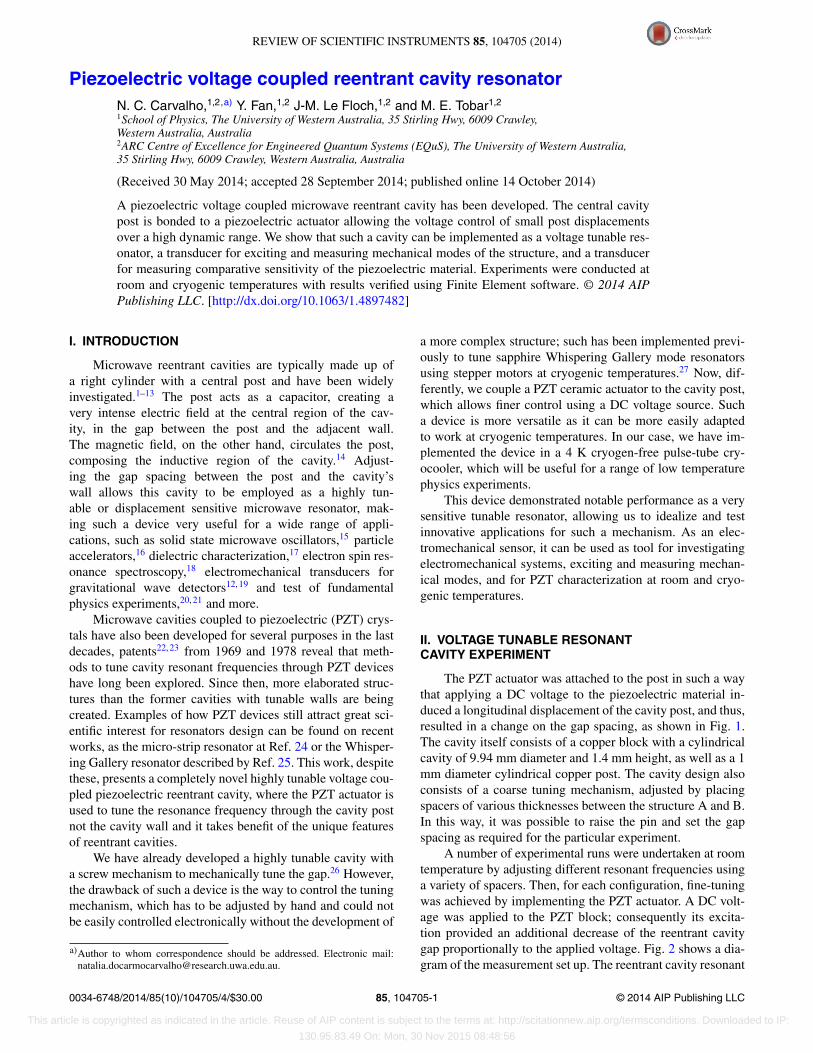
The PZT actuator was attached to the post in such a waythat applying a DC voltage to the piezoelectric material in-duced a longitudinal displacement of the cavity post, and thus,resulted in a change on the gap spacing, as shown in Fig. 1.The cavity itself consists of a copper block with a cylindricalcavity of 9.94 mm diameter and 1.4 mm height, as well as a 1mm diameter cylindrical copper post. The cavity design alsoconsists of a coarse tuning mechanism, adjusted by placingspacers of various thicknesses between the structure A and B.In this way, it was possible to raise the pin and set the gapspacing as required for the particular experiment.
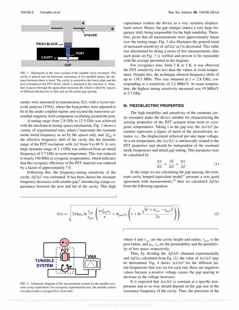
A number of experimental runs were undertaken at roomtemperature by adjusting different resonant frequencies usinga variety of spacers. Then, for each configuration, fine-tuningwas achieved by implementing the PZT actuator. A DC volt-age was applied to the PZT block; consequently its excita-tion provided an additional decrease of the reentrant cavitygap proportionally to the applied voltage. Fig. 2 shows a dia-gram of the measurement set up. The reentrant cavity resonant
0034-6748/2014/85(10)/104705/4/$30.00 © 2014 AIP Publishing LLC85, 104705-1
This article is copyrighted as indicated in the article. Reuse of AIP content is subject to the terms at: http://scitationnew.aip.org/termsconditions. Downloaded to IP:
130.95.83.49 On: Mon, 30 Nov 2015 08:48:56
104705-2 Carvalho et al. Rev. Sci. Instrum. 85, 104705 (2014)
FIG. 1. Illustration of the cross-section of the tunable cavity resonator. Thecavity is placed into an enclosure consisting of two parallel plates; the dis-tance between them is fixed. The cavity is screwed to the lower plate and thepost is bonded to the PZT block, which is attached to the structure A. Struc-ture A passes through the upper plate (structure B), which is lifted by spacersof different thicknesses to alter and set the initial gap spacing.
modes were measured in transmission, S21, with a vector net-work analyzer (VNA), where the loop probes were adjusted tobe in the under coupled regime and excited the transverse az-imuthal magnetic field component oscillating around the post.
A tuning range from 2.8 GHz to 12.5 GHz was achievedwith the mechanical tuning spacer mechanism. Fig. 3 shows avariety of experimental runs, where f represents the resonantmode initial frequency as set by the spacer only, and �feff isthe effective frequency shift of the cavity due the dynamicrange of the PZT excitation, with �U from 0 to 60 V. A verylarge dynamic range of 1.1 GHz was achieved from an initialfrequency of 5.7 GHz at room temperature. This was reducedto nearly 140 MHz at cryogenic temperatures, which indicatesthat the cryogenic efficiency of the PZT material was reducedby a factor of approximately 7.9.
Following this, the frequency-tuning sensitivity of thecavity �f/�U was estimated. It has been shown the resonantfrequency decreases with smaller gap,8 introducing a large ca-pacitance between the post and lid of the cavity. This high
capacitance renders the device as a very sensitive displace-ment sensor. Hence, the gap changes induce a very large fre-quency shift, being responsible for the high tunability. There-fore, given that all measurements were approximately linearover the tuning range, Fig. 3 also illustrates the general trendof increased sensitivity of �f/�U as f is decreased. This valuewas determined by doing a series of five measurements, thuseach point on Fig. 3 is verified and proven to be repeatablewith the average presented in the diagram.
For cryogenics runs, from 3 K to 5 K, it was observedthe PZT sensitivity was less than the values at room temper-ature. Despite this, the technique allowed frequency shifts ofup to 138.5 MHz. This was obtained at f = 2.8 GHz, cor-responding to a sensitivity of 2.2 MHz/V. At room tempera-ture, the highest tuning sensitivity measured was 19 MHz/Vat 5.7 GHz.
III. PIEZOELECTRIC PROPERTIES
The high tunability and sensitivity of the reentrant cav-ity resonator make the device suitable for characterizing thesensing properties of the PZT actuator from room to cryo-genic temperatures. Taking x as the gap size, the �x/�U pa-rameter represents a figure of merit of the piezoelectric ac-tuator, i.e., the displacement achieved per unit input voltage.At a set temperature, the �x/�U is intrinsically related to thePZT properties and should be independent of the reentrantmode frequencies and initial gap setting. This parameter maybe calculated by
�x
�U= �f
�U× �x
�f. (1)
In the range we are calculating the gap spacing, the reen-trant cavity lumped equivalent model11 presents a very goodagreement with measurements,26 then we calculated �f/�xfrom the following equation:
f(x) =
√√√√√2πhμ0 lnrcav
rpost
⎛⎝π r2
postε0
x+ 4rpostε0
⎛⎝1 + ln
√h2 + (rcav − rpost)
2
2x
⎞⎠
⎞⎠, (2)
FIG. 2. Schematic diagram of the measurement system for the tunable reso-nant cavity experiment. For cryogenic experimental runs, the tunable systemwas placed into a cryogen-free cryocooler.
where h and rcav are the cavity height and radius, rpost is thepost radius, and μ0, ε0 are the permeability and the permittiv-ity of free space, respectively.
Thus, by dividing the �f/�U obtained experimentallyand �f/�x calculated from Eq. (2), the value of �x/�U maybe determined. Fig. 4 shows �x/�U for the different ini-tial frequencies that was set for each run; these are negativesvalues because a positive voltage causes the gap spacing todecrease as the voltage increases.
It is expected that �x/�U is constant at a specific tem-perature and in no way should depend on the gap size or theresonance frequency of the cavity. Thus, the precision of the
This article is copyrighted as indicated in the article. Reuse of AIP content is subject to the terms at: http://scitationnew.aip.org/termsconditions. Downloaded to IP:
130.95.83.49 On: Mon, 30 Nov 2015 08:48:56

104705-3 Carvalho et al. Rev. Sci. Instrum. 85, 104705 (2014)
FIG. 3. Frequency-tuning sensitivity �f/�U. The dynamic range, �feff, wascaused by a voltage shift of 60 V. �f/�U and �feff are presented as a functionof the initial resonant frequency f (�U = 0 V).
�x/�U determination at a constant temperature can be im-proved by calculating its average along with its standard erroracross all measurements. At room temperature, the averagevalue is calculated to be −28.8 ± 3 nm/V and at 4 K, −5.1± 1 nm/V. These results mean that the PZT actuator at cryo-genic temperatures works at approximately 18% of its perfor-mance at room temperature or is reduced in sensitivity by afactor of 5.7.
IV. CAVITY ELECTROMECHANICAL PROPERTIES
The cavity resonant mode was also dynamically tuned bythe PZT actuator, which was driven by an AC voltage by using
FIG. 4. Modulus of the gap spacing displacement per unit volt, |�x/�U|,versus the initial reentrant resonant frequency. The solid lines are the averagevalues of |�x/�U|, while the detached areas correspond to the standard error.The solid triangles and squares represent the determination by measurements,based on the data in Fig. 3.
FIG. 5. Schematic diagram of the measurement system for frequencymodulation.
a Direct Digital Synthesizer (DDS). This induced a time vary-ing gap displacement and consequently produced a frequencymodulation at the PZT excitation rate. The measurement setupused is shown in Fig. 5. The top part (A) describes the PZTexcitation and the bottom part (B) illustrates the readout sys-tem. The frequency synthesizer (SYNTH) excited the cavityresonant frequency and the signal was transmitted through theresonator. The reflected signal was mixed with the synthesizerfrequency. In this configuration, the demodulated signal fromthe output of the mixer in the frequency discriminator is pro-portional to the mechanical displacement of the cavity post,which was measured using a Fast Fourier Transform (FFT)spectrum analyzer.
The modulation frequency was tuned from 2 kHz toabove 600 kHz, with the output of the FFT presented in Fig. 6.The prominent peaks are due to the frequency matching ofthe modulation frequency with the mechanical modes of the
FIG. 6. Mechanical modes of the cavity pin obtained due the PZT dynamicexcitation. Dark colors indicate maximum and light colors minimum dis-placement.
This article is copyrighted as indicated in the article. Reuse of AIP content is subject to the terms at: http://scitationnew.aip.org/termsconditions. Downloaded to IP:
130.95.83.49 On: Mon, 30 Nov 2015 08:48:56

104705-4 Carvalho et al. Rev. Sci. Instrum. 85, 104705 (2014)
cavity post, allowing readout of the mechanical resonances.Simulations based on Finite Element Method revealed twomechanical modes in this frequency range, at 150 kHz and340 kHz. The corresponding mode structure is on the right ofeach peak in Fig. 6. The lower frequency represents the modeof vibration of the whole pin, while the upper mode representsthe vibration of the top part of the pin, which has a smaller di-ameter. Thereby, we can say this tunable system presents itselfas an excellent electromechanical sensor, proved to be effi-cient for dynamic characterization of mechanical resonances.
V. CONCLUSION
A highly tunable voltage coupled piezoelectric reentrantcavity was constructed and tested, which showed a great per-formance as a tunable cavity and an electromechanical sen-sor. It has been demonstrated the system was able to be fine-tuned electronically over a large frequency range: 1.1 GHzat room temperature (19%) and 138.5 MHz (5%) at cryo-genic temperatures, at resonant frequencies of 5.7 GHz and2.8 GHz, respectively. In addition, the cavity exhibited a hightuning sensitivity. At room temperature, a sensitivity of 2.3–19 MHz/V was achieved, while at cryogenic temperatures therange was from 0.7 MHz/V to 2.2 MH/V. Moreover, we haveshown that the voltage tunable reentrant cavity can be usedfor determining piezoelectric sensitivity at different temper-atures, allowing a novel and highly precise technique for insitu characterization of piezoelectric materials. Also, we haveillustrated it was possible to excite and detect the mechani-cal modes of the cavity through the piezoelectric excitation.Consequently, the piezoelectric coupled reentrant cavity canbe used as a tool for investigating electromechanical systems.Therefore, we can conclude that interesting applications canbe drawn with such a device; in summary, with a single cavityit is possible to tune frequency resonances, characterize PZTactuators and have an electromechanical sensor.
ACKNOWLEDGMENTS
This research is supported by the Australian ResearchCouncil FL0992016, CE110001013 and by the ConselhoNacional de Desenvolvimento Científico e Tecnológico(CNPq – Brazil).
1W. W. Hansen, J. Appl. Phys. 10(1), 38 (1939).2M. Jaworski, IEEE Trans. Microwave Theory Tech. 26(4), 256 (1978).3D. P. Howson, IEE Proc., Part H: Microwaves, Opt. Antennas 131(6), 423–425 (1984).
4J. J. Barroso, P. J. Castro, O. D. Aguiar, and L. A. Carneiro, Rev. Sci.Instrum. 75(4), 1000–1005 (2004).
5A. Francik, in MIKON-2002: 14th International Conference on Mi-crowaves, Radar and Wireless Communications, 2002 (IEEE, 2002), Vol.1, pp. 103–106.
6C. Simon, M. Luong, S. Chel, O. Napoly, J. Novo, D. Roudier, N. Rouviere,N. Baboi, N. Mildner, and D. Nolle, Phys. Rev. Spec. Top.–Accel. Beams11(8), 082802 (2008).
7A. J. C. Vieira, P. R. Herczfeld, A. Rosen, M. Ermold, E. E. Funk, W. D.Jemison, and K. J. Williams, IEEE Trans. Microwave Theory Tech. 49(10),1882 (2001).
8X. Liu, L. P. B. Katehi, W. J. Chappell, and D. Peroulis, J. Microelec-tromech. Syst. 19(4), 774–784 (2010).
9F. Bordoni, L. Yinghua, B. Spataro, F. Feliciangeli, F. Vasarelli, G. Cardar-illi, B. Antonini, and R. Scrimaglio, Meas. Sci. Tech. 6, 1208 (1995).
10A. Kaczkowski and A. Milewski, IEEE Trans. Microwave Theory Tech.28(3), 225 (1980).
11K. Fujisawa, IRE Trans. Microwave Theory Tech. 6(4), 344 (1958).12N. P. Linthorne and D. G. Blair, Rev. Sci. Instrum. 63, 4154 (1992).13Y. Fan, Z. Zhang, N. C. Carvalho, J.-M. Le Floch, Q. Shan, and M. E.
Tobar, IEEE Trans. Microwave Theory Tech. 62(8), 1657–1662 (2014).14G. L. Pimentel, O. D. Aguiar, J. J. Barroso, and M. E. Tobar, J. Phys.: Conf.
Ser. 122, 012028 (2008).15A. G. Williamson, IEEE Trans. Microwave Theory Tech. 24, 182–187
(1976).16T. L. Grimm, A. Aizaz, M. Johnson, W. Hartung, F. Marti, D. Meidlinger,
M. Meidlinger, J. Popielarski, and R. C. York, IEEE Trans. Appl. Super-cond. 15, 2393 (2005).
17J. Baker-Jarvis, R. G. Geyer, J. H. Grosvenor, Jr., M. D. Janezic, C. A.Jones, B. Riddle, C. M. Weil, and J. Krupka, IEEE Trans. Dielectr. Electr.Insul. 5(4), 571 (1998).
18M. Giordano, F. Momo, and A. Sotgiu, J. Phys. E: Sci. Instrum. 16, 774(1983).
19O. D. Aguiar, J. J. Barroso, N. C. Carvalho et al., J. Phys.: Conf. Ser. 363,012003 (2012).
20G. Giunchi, A. Figini Albisetti, C. Braggio, G. Carugno, G. Messineo,G. Ruoso, G. Galeazzi, and F. Della Valle, IEEE Trans. Appl. Supercond.21(3), 745 (2011).
21S. K. Remillard, A. Hardaway, B. Mork, J. Gilliland, and J. Gibbs, Prog.Electromagn. Res. B 15, 175 (2009).
22R. E. Klotz, U.S. patent 3,471,811 (7 October 1969).23H. T. Buscher, W. F. Kolbe, and B. Leskovar, U.S. patent 4,110,686 (29
August 1978).24T. Faust, P. Krenn, S. Manus, J. P. Kotthaus, and E. M. Weig, Nat. Commun.
3, 728 (2012).25X. Han, C. Xiong, K. Y. Fong, X. Zhang, and H. X. Tang, New J. Phys.
16(6), 063060 (2014).26J.-M. Le Floch, Y. Fan, M. Aubourg, D. Cros, N. C. Carvalho, Q. Shan, J.
Bourhill, E. N. Ivanov, G. Humbert, V. Madrangeas, and M. E. Tobar, Rev.Sci. Instrum. 84, 125114 (2013).
27M. E. Tobar and D. G. Blair, IEEE Trans. Microwave Theory Tech. 39(9),1582 (1991).
This article is copyrighted as indicated in the article. Reuse of AIP content is subject to the terms at: http://scitationnew.aip.org/termsconditions. Downloaded to IP:
130.95.83.49 On: Mon, 30 Nov 2015 08:48:56