piezoelectric
DESCRIPTION
PiezoelectricTRANSCRIPT
Composite Structures 93 (2011) 3252–3261
Contents lists available at ScienceDirect
Composite Structures
journal homepage: www.elsevier .com/locate /compstruct
Higher order shear deformation effects on analysis of laminateswith piezoelectric fibre reinforced composite actuators
S.M. Shiyekar a,⇑, Tarun Kant b
a Department of Civil Engineering, Sinhgad College of Engineering, Vadgaon (Bk), Pune 411 041, Indiab Department of Civil Engineering, Indian Institute of Technology Bombay, Powai, Mumbai 400 076, India
a r t i c l e i n f o
Article history:Available online 24 May 2011
Keywords:Higher order theoryPiezoelectric fiber reinforced composites(PFRC)Laminates
0263-8223/$ - see front matter � 2011 Elsevier Ltd. Adoi:10.1016/j.compstruct.2011.05.016
⇑ Corresponding author. Tel.: +91 20 2410 0000; faE-mail address: [email protected] (S.M
a b s t r a c t
A complete analytical solution for cross-ply composite laminates integrated with piezoelectric fiber-rein-forced composite (PFRC) actuators under bi-directional bending is presented in this paper. A higher ordershear and normal deformation theory (HOSNT12) is used to analyze such hybrid or smart laminates sub-jected to electromechanical loading. The displacement function of the present model is approximated byemploying Taylor’s series in the thickness coordinate, while the electro-static potential is assumed to belayer wise (LW) linear through the thickness of PFRC. The equations of equilibrium are obtained usingprinciple of minimum potential energy and solution is by Navier’s technique. Transverse shear stressesare presented at the interface of PFRC actuator and laminate under the action of electrostatic potentials.Results are compared with first order shear deformation theory (FOST) and exact solution.
� 2011 Elsevier Ltd. All rights reserved.
1. Introduction
Piezoelectric materials transform elastic field into the electricfield and converse behavior leads many researchers to study theircontrolling capabilities applicable to structures like laminatedplates and shells. Such laminates are called smart, intelligent,adaptive as well as hybrid.
Piezoelectric materials show coupling phenomenon betweenelastic and electric fields. Tiersten and Mindlin [1] initiated workon piezoelectric plates. Tiersten [2] contributed further by estab-lishing the governing equations of linear piezoelectric continuumby studying vibrations of a single piezoelectric layer.
Mallik and Ray [3] proposed the concept of unidirectional pie-zoelectric fiber reinforced composite (PFRC) materials and pre-sented their effective elastic and piezoelectric properties usingmicromechanical analysis. Piezoelectric stress/strain coefficientsof PFRC are improved considerably as compared to monolithic pie-zoelectric materials.
Many investigators [4–11] studied hybrid laminates using vari-ous plate theories viz. equivalent single layer (ESL), layer wise (LW),zigzag and discrete layer theories (DLT) and also analytical solutionusing FOST [11]. Here in this paper a complete and simple analyt-ical solution is discussed using a higher order shear and normaldeformation theory.
ll rights reserved.
x: +91 20 2435 4721.. Shiyekar).
Ray et al. [12] developed three dimensional (3D) elasticity solu-tions for an intelligent plate simply supported and perfectlybonded with distributed polyvinylidene fluoride (PVDF) piezoelec-tric layers at top and bottom and presented static displacementcontrol of laminates for various span to depth ratios. Further Mal-lik and Ray [13,14] presented exact and finite element (FE) solu-tions for PFRC activated laminated composites respectively.Heyliger [15] obtained exact solution for an unsymmetric crossply composite laminate attached with PZT-4 layers of piezoelectricmaterial at upper and lower surfaces. Vel and Batra [16] usedEshelby-Stroh formulation to obtained 3D elasticity solution toanalyze multilayered piezoelectric plate with arbitrary boundaryconditions.
Initially Kant [17] developed complete set of variationallyconsistent governing equations of equilibrium and presentedfirst FE model based on higher order shear deformation theory(HOST) [18]. Pandya and Kant [19] and Kant and Manjunatha[20] extended the HOST for symmetric and unsymmetric lami-nates. Further Kant and Swaminathan [21] presented a refinedhigher order model and discussed analytical solution for sand-wiches and laminates. In this present paper, ESL based HOSNT12is used to model elastic quantities where as electrostatic poten-tial is by LW approach. Transverse shear and normal stresses areevaluated by using equations of equilibrium of elasticity. It is be-lieved that HOSNT12 will give accurate predictions of displace-ments and stresses. Further, a linear function for electrostaticpotential through actuating layer is considered sufficient in viewof its small thickness compared to that of the compositelaminate.
S.M. Shiyekar, T. Kant / Composite Structures 93 (2011) 3252–3261 3253
2. Formulation
2.1. Displacement function
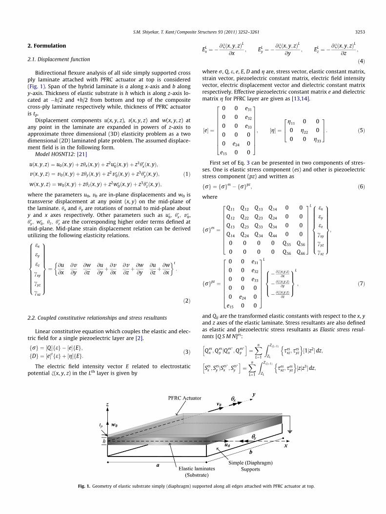
Bidirectional flexure analysis of all side simply supported crossply laminate attached with PFRC actuator at top is considered(Fig. 1). Span of the hybrid laminate is a along x-axis and b alongy-axis. Thickness of elastic substrate is h which is along z-axis lo-cated at �h/2 and +h/2 from bottom and top of the compositecross-ply laminate respectively while, thickness of PFRC actuatoris tp.
Displacement components u(x, y, z), v(x, y, z) and w(x, y, z) atany point in the laminate are expanded in powers of z-axis toapproximate three dimensional (3D) elasticity problem as a twodimensional (2D) laminated plate problem. The assumed displace-ment field is in the following form.
Model HOSNT12: [21]
uðx; y; zÞ ¼ u0ðx; yÞ þ zhxðx; yÞ þ z2u�0ðx; yÞ þ z3h�xðx; yÞ;vðx; y; zÞ ¼ v0ðx; yÞ þ zhyðx; yÞ þ z2v�0ðx; yÞ þ z3h�yðx; yÞ;
wðx; y; zÞ ¼ w0ðx; yÞ þ zhzðx; yÞ þ z2w�0ðx; yÞ þ z3h�zðx; yÞ;
ð1Þ
where the parameters u0, v0 are in-plane displacements and w0 istransverse displacement at any point (x, y) on the mid-plane ofthe laminate. hx and hy are rotations of normal to mid-plane abouty and x axes respectively. Other parameters such as u�0; h�x; v�0,h�y; w�0; hz; h�z are the corresponding higher order terms defined atmid-plane. Mid-plane strain displacement relation can be derivedutilizing the following elasticity relations.
ex
ey
ez
cxy
cyz
cxz
8>>>>>>>>>><>>>>>>>>>>:
9>>>>>>>>>>=>>>>>>>>>>;¼ @u
@x@v@y
@w@z
@u@yþ @v@x
@v@zþ @w@y
@u@zþ @w@x
� �t
:
ð2Þ
2.2. Coupled constitutive relationships and stress resultants
Linear constitutive equation which couples the elastic and elec-tric field for a single piezoelectric layer are [2].
frg ¼ ½Q �feg � ½e�fEg;fDg ¼ ½e�tfeg þ ½g�fEg:
ð3Þ
The electric field intensity vector E related to electrostaticpotential n(x, y, z) in the Lth layer is given by
Fig. 1. Geometry of elastic substrate simply (diaphragm) supp
ELx ¼ �
@nðx; y; zÞL
@x; EL
y ¼ �@nðx; y; zÞL
@y; EL
z ¼ �@nðx; y; zÞL
@z;
ð4Þ
where r, Q, e, e, E, D and g are, stress vector, elastic constant matrix,strain vector, piezoelectric constant matrix, electric field intensityvector, electric displacement vector and dielectric constant matrixrespectively. Effective piezoelectric constant matrix e and dielectricmatrix g for PFRC layer are given as [13,14].
½e� ¼
0 0 e31
0 0 e32
0 0 e33
0 0 0
0 e24 0
e15 0 0
26666666664
37777777775; ½g� ¼
g11 0 0
0 g22 0
0 0 g33
264
375: ð5Þ
First set of Eq. 3 can be presented in two components of stres-ses. One is elastic stress component (es) and other is piezoelectricstress component (pz) and written as
frg ¼ frges � frgpz; ð6Þ
where
frges ¼
Q11 Q 12 Q 13 Q 14 0 0
Q12 Q 22 Q 23 Q 24 0 0
Q13 Q 23 Q 33 Q 34 0 0
Q14 Q 24 Q 34 Q 44 0 0
0 0 0 0 Q 55 Q56
0 0 0 0 Q 56 Q66
26666666664
37777777775
L ex
ey
ez
cxy
cyz
cxz
8>>>>>>>>><>>>>>>>>>:
9>>>>>>>>>=>>>>>>>>>;;
frgpz ¼
0 0 e31
0 0 e32
0 0 e33
0 0 0
0 e24 0
e15 0 0
26666666664
37777777775
L
� @nðx;y;zÞ@x
� @nðx;y;zÞ@y
� @nðx;y;zÞ@z
8>><>>:
9>>=>>;
L
; ð7Þ
and Qij are the transformed elastic constants with respect to the x, yand z axes of the elastic laminate. Stress resultants are also definedas elastic and piezoelectric stress resultants as Elastic stress resul-tants [Q S M N]es:
Qesx ;Q
esy jQ
es�
x ;Q es�
y
h i¼Xn
L¼1
Z ZðLþ1Þ
ZL
sesxz; s
esyz
n o½1jz2�dz;
Sesx ; S
esy jS
es�
x ; Ses�
y
h i¼Xn
L¼1
Z ZðLþ1Þ
ZL
sesxz; s
esyz
n o½zjz3�dz;
orted along all edges attached with PFRC actuator at top.
3254 S.M. Shiyekar, T. Kant / Composite Structures 93 (2011) 3252–3261
Mesx ;M
esy ;M
esxy
h ���Mes�
x ;Mes�
y ;Mes�
xy
i¼Xn
L¼1
Z ZðLþ1Þ
ZL
resx ;r
esy ; s
esxy
n o½zjz3�dz;
Mesz ¼
Xn
L¼1
Z ZðLþ1Þ
ZL
zresz dz;
Nesx ;N
esy ;N
esz ;N
esxy
h ���Nes�
x ;Nes�
y ;Nes�
z ;Nes�
xy
i
¼Xn
L¼1
Z ZðLþ1Þ
ZL
resx ;r
esy ;r
esz ; s
esxy
n o½1jz2�dz: ð8Þ
Piezoelectric stress resultants [Q S M N]pz:
Q pzx ;Q
pzy jQ
pz�
x ;Q pz�
y
h i¼Z h=2þtp
þh=2spz
xz ; spzyz
n o½1jz2�dz;
Spzx ; S
pzy jS
pz�
x ; Spz�
y
h i¼Z h=2þtp
þh=2spz
xz ; spzyz
n o½zjz3�dz;
Mpzx ;M
pzy ;M
pzxyjM
pz�
x ;Mpz�
y ;Mpz�
xy
h i¼Z h=2þtp
þh=2rpz
x ;rpzy ; s
pzxy
n o½zjz3�dz;
Mpzz ¼
Z h=2þtp
þh=2zrpz
z dz;
Npzx ;N
pzy ;N
pzz ;N
pzxyjN
pz�
x ;Npz�
y ;Npz�
z ;Npz�
xy
h i
¼Z h=2þtp
þh=2rpz
x ;rpzy ;r
pzz ; s
pzxy
n o½1jz2�dz: ð9Þ
Total stress resultants½Q S M N�¼ ½Q S M N�es þ ½Q S M N�pz
: ð10Þ
Governing equations of equilibrium: [21]Using principle of minimum potential energy, the equations of
equilibrium are obtained as
du0 : @Nx@x þ
@Nxy
@y ¼ 0 du�0 : @N�x@x þ
@N�xy
@y � 2Sx ¼ 0
dv0 :@Ny
@y þ@Nxy
@x ¼ 0 dv�0 :@N�y@y þ
@N�xy
@x � 2Sy ¼ 0
dw0 : @Qx@x þ
@Qy
@y þ ðqþz Þ ¼ 0 dw�0 : @Q�x@x þ
@Q�y@y � 2M�
z þ h2
4 ðqþz Þ ¼ 0
dhx : @Mx@x þ
@Mxy
@y � Qx ¼ 0 dh�x : @M�x@x þ
@M�xy
@y � 3Q �x ¼ 0
dhy :@My
@y þ@Mxy
@x � Q y ¼ 0 dh�y :@M�y@y þ
@M�xy
@x � 3Q �y ¼ 0
dhz : @Sx@x þ
@Sy
@y � Nz þ h2 ðqþz Þ ¼ 0 dh�z : @S�x
@x þ@S�y@y � 3N�z þ h3
8 ðqþz Þ ¼ 0:
ð11Þ
Following are the mechanical and electrical in-plan boundaryconditions used for simply supported plate
At edges x = 0 and x = a:
v0 ¼ 0; w0 ¼ 0; hy ¼ 0; hz ¼ 0; Mx ¼ 0; Nx ¼ 0; v�0 ¼ 0;
w�0 ¼ 0; h�y ¼ 0; h�z ¼ 0; M�x ¼ 0; N�x ¼ 0; n ¼ 0:
At edges y = 0 and y = b:
u0 ¼ 0; w0 ¼ 0; hx ¼ 0; hz ¼ 0; My ¼ 0; Ny ¼ 0; u�0 ¼ 0;
w�0 ¼ 0; h�x ¼ 0; h�z ¼ 0; M�y ¼ 0; N�y ¼ 0; n ¼ 0:
In Navier’s solution procedure the load, electric potential andmid-plane displacements are expanded as follows, satisfying theabove boundary conditions.
u0 ¼P1
m¼1;3;5
P1n¼1;3;5
u0mn cos mpxa
� �sin npy
b
� �
u�0 ¼P1
m¼1;3;5
P1n¼1;3;5
u�0mncos mpx
a
� �sin npy
b
� �
v0 ¼P1
m¼1;3;5
P1n¼1;3;5
v0mn sin mpxa
� �cos npy
b
� �
v�0 ¼P1
m¼1;3;5
P1n¼1;3;5
v�0mnsin mpx
a
� �cos npy
b
� �
w0 ¼P1
m¼1;3;5
P1n¼1;3;5
w0mn sin mpxa
� �sin npy
b
� �
w�0 ¼P1
m¼1;3;5
P1n¼1;3;5
w�0mnsin mpx
a
� �sin npy
b
� �
hx ¼P1
m¼1;3;5
P1n¼1;3;5
hxmn cos mpxa
� �sin npy
b
� �
h�x ¼P1
m¼1;3;5
P1n¼1;3;5
h�xmncos mpx
a
� �sin npy
b
� �
hy ¼P1
m¼1;3;5
P1n¼1;3;5
hymnsin mpx
a
� �cos npy
b
� �
h�y ¼P1
m¼1;3;5
P1n¼1;3;5
h�ymnsin mpx
a
� �cos npy
b
� �
hz ¼P1
m¼1;3;5
P1n¼1;3;5
hzmn sin mpxa
� �sin npy
b
� �
h�z ¼P1
m¼1;3;5
P1n¼1;3;5
h�zmnsin mpx
a
� �sin npy
b
� �
qþz ¼P1
m¼1;3;5
P1n¼1;3;5
qþzmnsin mpx
a
� �sin npy
b
� �:
ð12Þ
and electrostatic potential is as
nðx; y; zÞ ¼X1
m¼1;3;5
X1n¼1;3;5
nmnðzÞ sinmpx
a
� �sin
npyb
� �:
The above expansions are substituted in the equilibrium equa-tions (Eq. 11) which yield the following algebraic system ofequations.
½X�12x12
u0
v0
w0
hx
hy
hz
u�0v�0w�0h�xh�yh�z
8>>>>>>>>>>>>>>>>>>>>>>>>>><>>>>>>>>>>>>>>>>>>>>>>>>>>:
9>>>>>>>>>>>>>>>>>>>>>>>>>>=>>>>>>>>>>>>>>>>>>>>>>>>>>;
12x1
¼
0
0
qþz0
0
ðh=2Þqþz0
0
ðh2=4Þqþz0
0
ðh3=8Þqþz
8>>>>>>>>>>>>>>>>>>>>>>>>>><>>>>>>>>>>>>>>>>>>>>>>>>>>:
9>>>>>>>>>>>>>>>>>>>>>>>>>>=>>>>>>>>>>>>>>>>>>>>>>>>>>;
12x1
� Vt
Vz1
Vz2
Vz3
Vz4
Vz5
Vz6
Vz7
Vz8
Vz9
Vz10
Vz11
Vz12
8>>>>>>>>>>>>>>>>>>>>>>>>>><>>>>>>>>>>>>>>>>>>>>>>>>>>:
9>>>>>>>>>>>>>>>>>>>>>>>>>>=>>>>>>>>>>>>>>>>>>>>>>>>>>;
12x1
; ð13Þ
where [X] is elastic stiffness matrix derived by Kant and Swamina-than [21]. Elements of voltage vector {Vzi} are given in Appendix A.qþz is the mechanical loading term and n(x, y, z) is the electrical load-ing term. Through thickness electric potential nmn(z) is assumed asper the following sub-section.
2.3. Electrostatic potential
The elastic substrate is attached with distributed actuator layerof PFRC. Thickness of the PFRC layer is small as compared to thick-ness of the substrate. Electro-static potential in the actuator layer
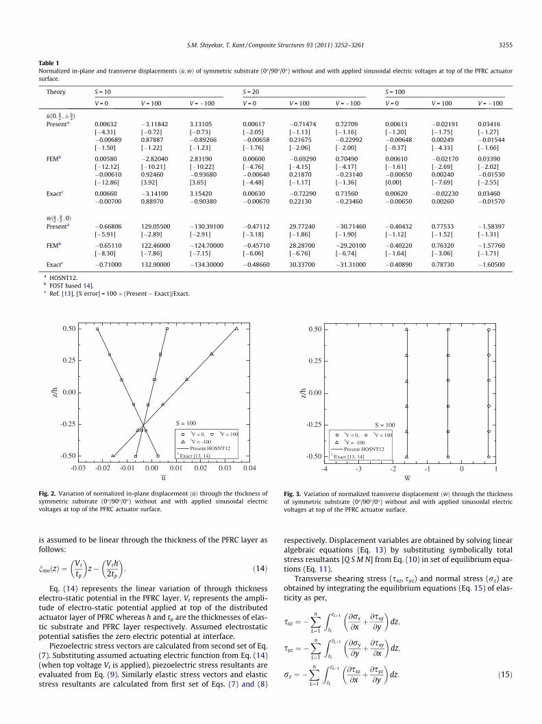
Table 1Normalized in-plane and transverse displacements ð�u; �wÞ of symmetric substrate (0�/90�/0�) without and with applied sinusoidal electric voltages at top of the PFRC actuatorsurface.
Theory S = 10 S = 20 S = 100
V = 0 V = 100 V = �100 V = 0 V = 100 V = �100 V = 0 V = 100 V = �100
�u 0; b2 ;� h
2
� �Presenta 0.00632 �3.11842 3.13105 0.00617 �0.71474 0.72709 0.00613 �0.02191 0.03416
[�4.31] [�0.72] [�0.73] [�2.05] [�1.13] [�1.16] [�1.20] [�1.75] [�1.27]�0.00689 0.87887 �0.89266 �0.00658 0.21675 �0.22992 �0.00648 0.00249 �0.01544[�1.50] [�1.22] [�1.23] [�1.76] [�2.06] [�2.00] [�0.37] [�4.33] [�1.66]
FEMb 0.00580 �2.82040 2.83190 0.00600 �0.69290 0.70490 0.00610 �0.02170 0.03390[�12.12] [�10.21] [�10.22] [�4.76] [�4.15] [�4.17] [�1.61] [�2.69] [�2.02]�0.00610 0.92460 �0.93680 �0.00640 0.21870 �0.23140 �0.00650 0.00240 �0.01530[�12.86] [3.92] [3.65] [�4.48] [�1.17] [�1.36] [0.00] [�7.69] [�2.55]
Exactc 0.00660 �3.14100 3.15420 0.00630 �0.72290 0.73560 0.00620 �0.02230 0.03460�0.00700 0.88970 �0.90380 �0.00670 0.22130 �0.23460 �0.00650 0.00260 �0.01570
�wða2 ; b2 ;0Þ
Presenta �0.66806 129.05500 �130.39100 �0.47112 29.77240 �30.71460 �0.40432 0.77533 �1.58397[�5.91] [�2.89] [�2.91] [�3.18] [�1.86] [�1.90] [�1.12] [�1.52] [�1.31]
FEMb �0.65110 122.46000 �124.70000 �0.45710 28.28700 �29.20100 �0.40220 0.76320 �1.57760[�8.30] [�7.86] [�7.15] [�6.06] [�6.76] [�6.74] [�1.64] [�3.06] [�1.71]
Exactc �0.71000 132.90000 �134.30000 �0.48660 30.33700 �31.31000 �0.40890 0.78730 �1.60500
a HOSNT12.b FOST based 14].c Ref. [13], [% error] = 100 � (Present � Exact)/Exact.
-0.03 -0.02 -0.01 0.00 0.01 0.02 0.03 0.04
-0.50
-0.25
0.00
0.25
0.50
1V = 0, 1V = 1001V = -100 Present HOSNT12
1 Exact [14, 15]
1V = 0, 1V = 1001V = -100 Present HOST12
1 Exact [14, 15]
z/h
u
1V = 0, 1V = 1001V = -100 Present HOSNT12
1 Exact [13, 14]
S = 100
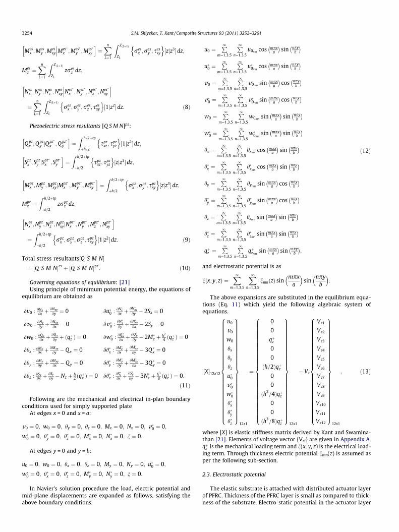
Fig. 2. Variation of normalized in-plane displacement ð�uÞ through the thickness ofsymmetric substrate (0�/90�/0�) without and with applied sinusoidal electricvoltages at top of the PFRC actuator surface.
-4 -3 -2 -1 0 1
-0.50
-0.25
0.00
0.25
0.50
1V = 0, 1V = 1001V = -100 Present HOSNT12
1 Exact [13, 14]
z/h
w
S = 100
Fig. 3. Variation of normalized transverse displacement ð �wÞ through the thicknessof symmetric substrate (0�/90�/0�) without and with applied sinusoidal electricvoltages at top of the PFRC actuator surface.
S.M. Shiyekar, T. Kant / Composite Structures 93 (2011) 3252–3261 3255
is assumed to be linear through the thickness of the PFRC layer asfollows:
nmnðzÞ ¼Vt
tp
z� Vth
2tp
: ð14Þ
Eq. (14) represents the linear variation of through thicknesselectro-static potential in the PFRC layer. Vt represents the ampli-tude of electro-static potential applied at top of the distributedactuator layer of PFRC whereas h and tp are the thicknesses of elas-tic substrate and PFRC layer respectively. Assumed electrostaticpotential satisfies the zero electric potential at interface.
Piezoelectric stress vectors are calculated from second set of Eq.(7). Substituting assumed actuating electric function from Eq. (14)(when top voltage Vt is applied), piezoelectric stress resultants areevaluated from Eq. (9). Similarly elastic stress vectors and elasticstress resultants are calculated from first set of Eqs. (7) and (8)
respectively. Displacement variables are obtained by solving linearalgebraic equations (Eq. 13) by substituting symbolically totalstress resultants [Q S M N] from Eq. (10) in set of equilibrium equa-tions (Eq. 11).
Transverse shearing stress (sxz, syz) and normal stress (rz) areobtained by integrating the equilibrium equations (Eq. 15) of elas-ticity as per,
sxz ¼ �Xn
L¼1
Z zLþ1
zL
@rx
@xþ @sxy
@y
dz;
syz ¼ �Xn
L¼1
Z zLþ1
zL
@ry
@yþ @sxy
@x
dz;
rz ¼ �Xn
L¼1
Z zLþ1
zL
@sxz
@xþ @syz
@y
dz: ð15Þ

Table 2Normalized in-plane and transverse normal stresses ð�rx ; �ry; �rzÞ of symmetric substrate (0�/90�/0�) without and with applied sinusoidal electric voltages at top of the PFRCactuator surface.
Theory S = 10 S = 20 S = 100
V = 0 V = 100 V = �100 V = 0 V = 100 V = �100 V = 0 V = 100 V = �100
�rxa2 ;
b2 ;� h
2
� �Presenta �0.50746 247.54300 �248.55800 �0.49326 56.75720 �57.74370 �0.48872 1.73795 �2.71540
[�3.91] [�0.49] [�0.51] [�2.03] [�0.89] [�0.91] [�1.23] [�0.97] [�1.06]0.55160 �70.76880 71.87200 0.52389 �17.41310 18.46090 0.51439 �0.20484 1.23362[�1.90] [�1.25] [�1.26] [�1.25] [�2.23] [�2.19] [�0.94] [�6.08] [�1.83]
FEMb �0.49150 235.46000 �236.40000 �0.50220 57.26700 �58.27600 �0.49410 1.74830 �2.73640[�6.93] [�5.35] [�5.37] [�0.26] [0.00] [0.00] [�0.14] [�0.38] [�0.30]0.52150 �71.56500 72.57000 0.53040 �17.09000 18.07400 0.51210 0.21060 1.24780[�7.26] [�0.14] [�0.30] [�0.02] [�4.04] [�4.24] [�1.39] [�196.56] [�0.70]
Exactc �0.52810 248.76000 �249.82000 �0.50350 57.26900 �58.27600 �0.49480 1.75490 �2.744500.56230 �71.66600 72.79000 0.53050 �17.81000 18.87500 0.51930 �0.21810 1.25660
�rya2 ;
b2 ;� h
6
� �Presenta �0.23729 39.40750 �39.88210 �0.18114 9.95995 �10.32220 �0.16003 0.24780 �0.56786
[�7.71] [�7.35] [�7.35] [�4.71] [�4.77] [�4.78] [�2.60] [�4.54] [�3.46]0.26263 �56.27130 56.79660 0.19960 �14.09780 14.49700 0.17609 �0.39707 0.74924[�6.17] [�2.42] [�2.46] [�2.35] [�0.44] [�0.47] [0.16] [0.40] [0.30]
FEMb �0.23480 34.17500 �34.64500 �0.18490 9.88800 �10.25800 �0.16410 0.25710 �0.58070[�8.67] [�19.65] [�19.52] [�2.74] [�5.46] [�5.37] [�0.12] [�0.96] [�1.28]0.25730 �51.29500 51.80900 0.20400 �14.12500 14.52900 0.17070 �0.39260 0.74280[�8.07] [�11.05] [�11.02] [�0.20] [�0.25] [�0.25] [�2.90] [�0.73] [�0.56]
Exactc �0.25710 42.53200 �43.04600 �0.19010 10.45900 �10.84000 �0.16430 0.25960 �0.588200.27990 �57.66700 58.22700 0.20440 �14.16000 14.56600 0.17580 �0.39550 0.74700
�rza2 ;
b2 ;0
� �Presenta �0.47467 53.72950 �54.67880 �0.47661 – – �0.47728 0.09546 �1.05002
[�1.22] [9.31] [9.11] [�1.81] – – [�1.71] [141.31] [3.88]Exactc �0.48052 49.15300 �50.11400 �0.48540 1.61150 �2.58240 �0.48560 0.03956 �1.01080
a HOSNT12.b FOST based [14].c Ref. [13], [% error] = 100 � (Present � Exact)/Exact.
-3 -2 -1 0 1 2-0.50
-0.25
0.00
0.25
0.50
1V = 0, 1V = 1001V = -100 Present HOSNT12
1 Exact [13, 14]
z/h
σx
S = 100
Fig. 4. Variation of normalized in-plane normal stress ð�rxÞ through the thickness ofsymmetric substrate (0�/90�/0�) without and with applied sinusoidal electricvoltages at top of the PFRC actuator surface.
-0.8 -0.6 -0.4 -0.2 0.0 0.2 0.4 0.6 0.8
-0.50
-0.25
0.00
0.25
0.50 1V = 0, 1V = 1001V = -100 Present HOSNT12
1 Exact [13, 14]S = 100
z/h
σy
Fig. 5. Variation of normalized in-plane normal stress ð�ryÞ through the thickness ofsymmetric substrate (0�/90�/0�) without and with applied sinusoidal electricvoltages at top of the PFRC actuator surface.
3256 S.M. Shiyekar, T. Kant / Composite Structures 93 (2011) 3252–3261
3. Numerical results
A hybrid all side simply (diaphragm) supported cross ply lami-nates (substrate) is considered [13,14]. Substrate consists of elasticbi-directional orthotropic layers of graphite/epoxy composite. Pie-zoelectric material of PFRC attached at top of the elastic substrate
is in a distributed form. The material properties of elastic orthotro-pic layers are as [13].
EL ¼ 172:9 GPa;EL
ET¼ 25; GLT ¼ 0:5ET ; GTT ¼ 0:2ET ;
mLT ¼ mTT ¼ 0:25; ð16Þ

-2.0 -1.6 -1.2 -0.8 -0.4 0.0 0.4
-0.50
-0.25
0.00
0.25
0.50
1V = 0, 1V = 1001V = -100 Present HOSNT12
1 Exact [13, 14]
z/h
σz
S = 100
Fig. 6. Variation of normalized transverse normal stress ð�rzÞ through the thicknessof symmetric substrate (0�/90�/0�) without and with applied sinusoidal electricvoltages at top of the PFRC actuator surface.
-2.0 -1.5 -1.0 -0.5 0.0 0.5 1.0 1.5 2.0
-0.50
-0.25
0.00
0.25
0.50
1V = 0, 1V = 1001V = -100 Present HOSNT12
1 Exact [13, 14]
S = 100
z/h
τxz
Fig. 7. Variation of normalized transverse shear stress ð�sxzÞ through the thickness ofsymmetric substrate (0�/90�/0�) without and with applied sinusoidal electricvoltages at top of the PFRC actuator surface.
S.M. Shiyekar, T. Kant / Composite Structures 93 (2011) 3252–3261 3257
L signifies direction parallel to fiber direction and T the transversedirection.
The material properties of PFRC layer are as follows [13].
C11 ¼ 32:6 GPa; C12 ¼ C21 ¼ 4:3 GPa;C13 ¼ C31 ¼ 4:76 GPa; C22 ¼ C33 ¼ 7:2 GPa;C23 ¼ 3:85 GPa; C44 ¼ 1:05 GPa; C55 ¼ C66 ¼ 1:29 GPa;e31 ¼ �6:76 C=m2; g11 ¼ g22 ¼ 0:037E� 9 C=V m;
g33 ¼ 10:64E� 9 C=V m:
ð17Þ
Numerical results are computed by taking m = n = 1.
Case i: Doubly sinusoidal mechanical load (qþz ¼ 40 N=m2,downward) without applied voltage at top of actuator (V = 0).Case ii: Doubly sinusoidal mechanical load (qþz ¼ 40 N=m2,downward) with doubly sinusoidal applied voltage of positivepolarity at top of actuator (Vt = +100 V).
Table 3Normalized in-plane and transverse shear stresses ð�sxy ; �sxz ; �syzÞ of symmetric substrateactuator surface.
Theory S = 10 S = 20
V = 0 V = 100 V = �100 V = 0
�sxy 0;0;� h2
� �Presenta 0.02473 �7.56623 7.61569 0.02084
[�5.24] [�1.69] [�1.71] [�3.09]�0.02643 4.52824 �4.58109 �0.02191[�4.25] [�1.96] [�1.99] [�2.20]
FEMb 0.02410 �7.00660 7.05470 0.02140[�7.66] [�8.96] [�8.95] [�0.47]�0.02510 4.24190 �4.29200 �0.02240[�9.06] [�8.16] [�8.17] [0.00]
Exactc 0.02610 �7.69600 7.74800 0.02150�0.02760 4.61900 �4.67400 �0.02240
�sxz 0; b2 ;0
� �Presenta �0.35304 23.02620 �23.73220 �0.37465
[2.40] [�2.47] [�2.33] [�2.26]
Exact �0.34476 23.60900 �24.29800 �0.38330
�syza2 ;0;0� �
Presenta �0.11596 23.94060 �24.17250 �0.09144[�4.23] [�0.52] [�0.55] [9.91]
Exactc �0.12108 24.06500 �24.30700 �0.08320
a HOSNT12.b FOST based [14].c Ref. [13], [% error] = 100 � (Present � Exact)/Exact.
Case iii: Doubly sinusoidal mechanical load ðqþz ¼ 40 N=m2,downward) with doubly sinusoidal applied voltage of negativepolarity at top of actuator (Vt = �100 V).
The above three load cases are represented by the followingloads:
qþz ¼X1
m¼1;3;5
X1n¼1;3;5
�40 sinmpx
a
� �sin
npyb
� �and
n x; y;h2þ tp
¼
X1m¼1;3;5
X1n¼1;3;5
�100 sinmpx
a
� �sin
npyb
� �: ð18Þ
Different values for length to thickness of substrate/laminateratios S = a/h are considered. The thickness of actuator is 250 lmand that of each orthotropic layer is 1 mm. Edges (x = 0, a and
(0�/90�/0�) without and with applied sinusoidal electric voltages at top of the PFRC
S = 100
V = 100 V = �100 V = 0 V = 100 V = �100
�1.79126 1.83293 0.01942 �0.05187 0.09071[�1.69] [�1.71 [�1.43] [�1.58] [�1.62]1.10547 �1.14928 �0.02028 0.02462 �0.06518[�1.58] [�1.59] [�0.59] [�1.74] [�1.18]
�1.81400 1.85650 0.01970 �0.05260 0.09150[�0.44] [�0.45] [0.00] [�0.19] [�0.76]1.12320 �1.16790 �0.02040 0.02502 �0.06580[0.00] [0.00] [0.00] [�0.16] [�0.24]
�1.82200 1.86480 0.01970 �0.05270 0.092201.12320 �1.16790 �0.02040 0.02506 �0.06596
– – �0.38249 �0.12410 �0.64088– – [�0.57] [5.67] [�1.70]
0.68194 �1.44850 �0.38470 �0.11744 �0.65197
– – �0.08232 0.16094 �0.32558– – [0.64] [1.05] [0.85]
0.88142 �1.04780 �0.08180 0.15927 �0.32284

-0.3 -0.2 -0.1 0.0 0.1 0.2
-0.50
-0.25
0.00
0.25
0.50
1V = 0, 1V = 1001V = -100 Present HOSNT12
1 Exact [13, 14]
S = 100
z/h
τyz
Fig. 8. Variation of normalized transverse shear stress ð�syzÞ through the thickness ofsymmetric substrate (0�/90�/0�) without and with applied sinusoidal electricvoltages at top of the PFRC actuator surface.
0 20 40 60 80 100
-200
-150
-100
-50
0
50
100
150
200
00/900/900/00
V = 0
V = -200
V = 100
V = -100
V = 200
Present HOSNT12Exact [13, 14]
w
S = a/h
Fig. 9. Variation of normalized transverse displacement (w) with respect to aspectratio (S = a/h) of symmetric substrate (0�/90�/90�/0�) without and with appliedsinusoidal electric voltages at top of the PFRC actuator surface.
3258 S.M. Shiyekar, T. Kant / Composite Structures 93 (2011) 3252–3261
y = 0, b) of the hybrid laminate are grounded and in thicknessdirection also, substrate is not permitting any charge.
The results are normalized as:
�u 0; b2 ;� h
2
� �¼ E2
q0S3hu; �w a
2 ;b2 ;0
� �¼ 100E2
q0S4hw;
�rxa2 ;
b2 ;� h
2
� �¼ rx
q0S2 ; �rya2 ;
b2 ;� h
6
� �¼ ry
q0S2 ; �rza2 ;
b2 ;0
� �¼ rz
q0;
�sxy 0;0;� h2
� �¼ sxy
q0S2 ; �syza2 ; 0;0� �
¼ syz
q0S ; �sxz 0; b2 ;0
� �¼ sxz
q0S :
ð19Þ
E2 is transverse Young’s modulus of the elastic orthotropic layer.Three laminate configurations are taken into consideration: threelayered symmetric [0�/90�/0�], four layered symmetric [0�/90�/90�/0�] and four layered antisymmetric [0�/90�/0�/90�].
Results are compared with 3D exact solution [13] and FE solu-tion based on FOST [14].
Normalized in-plane and transverse displacements ð�u; �wÞ aredemonstrated for hybrid laminate [0�/90�/0�] in Table 1 subjectedto mechanical pressure, positive and negative polarity voltages forvarious aspect ratios (S = 10, 20 and 100). In case of moderatelythick laminate (S = 10) subjected to electrostatic loading (Case iiand case iii), % error in in-plane displacement ð�uÞ of present HOS-NT12 is up to 0.72 where as for FOST based FEM is 10.21. HOSNT12
Table 4Normalized in-plane and transverse displacements ð�u; �wÞ of symmetric substrate (0�/90�/90surface.
Theory S = 10 S = 20
V = 0 V = 100 V = �100 V = 0 V = 100 V = �1
�u 0; b2 ;� h
2
� �Presenta 0.0063 �2.5543 2.5669 0.0063 �0.5917 0.6042
[�1.84] [0.32] [�0.09] [�0.70] [�0.27] [�0.28�0.0068 0.5105 �0.5241 �0.0066 0.1097 �0.12[0.48] [10.52] [10.23] [�0.84] [0.83] [0.73]
Exactb 0.0064 �2.5463 2.5691 0.0063 �0.5933 0.6059�0.0068 0.4619 �0.4755 �0.0067 0.1088 �0.12
�w a2 ;
b2 ; 0
� �Presenta �0.6893 96.2234 �97.6020 �0.4833 22.1061 �23.0
[�3.41] [2.47] [2.40] [�1.76] [�0.16] [�0.23
Exactb �0.7137 93.9010 �95.3180 �0.4920 22.1410 �23.1
a HOSNT12.b Ref. [13], [% error] = 100 � (Present � Exact)/Exact.
and FEM under predict results in normalized transverse displace-ment ð�wÞwith 2.89 and 7.15% deviation respectively. It is observedthat present HOSNT12 yields most accurate results of displace-ment quantities as compared to FOST based FEM. Actuating volt-ages (Case ii and Case iii) produce in-plane displacementresponse ð�uÞ nearly 475 times more for S = 10, 116 times forS = 20 and 5 times for S = 100 as compared with no voltage case(Case i). In case of transverse displacement ð�wÞ the actuation re-sponse is nearly 200 times for S = 10 and 4 times for S = 100 thanthat of no actuation case. It is observed that the actuating voltageis more effective in case of thick laminates rather than thin. PresentHOSNT12 exhibits excellent performance in all the loading casesand aspect ratios for normalized in-plane and transverse displace-ments ð�u; �wÞ over FOST based on FEM. This is due to cubical varia-tion in approximation of in-plane displacement as well as intransverse normal displacement components ð�u; �wÞ. Throughthickness variations of in-plane displacements ð�uÞ and transversedisplacements ð�wÞ are presented in Figs. 2 and 3 respectively. Asfar as thin plate (S = 100) is concerned, variations for displace-ments are linear and constant through the thickness of the
�/0�) without and with applied sinusoidal electric voltages at top of the PFRC actuator
S = 50 S = 100
00 V = 0 V = 100 V = �100 V = 0 V = 100 V = �100
0.0062 �0.0872 0.0997 0.0063 �0.0170 0.0295] [�0.74] [�0.38] [�0.86]
30 �0.0066 0.0114 �0.0246 �0.0066 �0.0021 �0.0111[�0.08] [4.98] [�0.99]
0.0063 �0.0171 0.029821 �0.0066 �0.0020 �0.0112
727 �0.4210 3.1248 �3.9669 �0.4119 0.4722 �1.2961] [�0.95] [�1.06] [�0.98]
250 �0.4159 0.4772 �1.3089

Table 5Normalized in-plane and transverse normal stresses ð�rx ; �ry; �rzÞ of symmetric substrate (0�/90�/90�/0�) without and with applied sinusoidal electric voltages at top of the PFRCactuator surface.
Theory S = 10 S = 20 S = 50 S = 100
V = 0 V = 100 V = �100 V = 0 V = 100 V = �100 V = 0 V = 100 V = �100 V = 0 V = 100 V = �100
�rxa2 ;
b2 ;� h
2
� �Presenta �0.5091 205.435 �206.4530 �0.5014 47.1483 �48.1510 �0.4992 6.9249 �7.9233 �0.4989 1.3497 �2.3475
[�0.78] [1.95] [1.94] [�0.74] [0.39] [0.36] [�0.95] [�0.39] [�0.63]0.5325 �31.2141 32.2792 0.5244 �8.1721 9.2209 0.5236 �0.9193 1.9667 0.5237 0.1609 0.8865[�2.04] [�16.72] [�16.30] [�1.17] [�7.62] [�6.93] [�0.01] [4.25] [�1.53]
Exactb �0.5131 201.5000 �202.5200 �0.5051 46.9660 �47.9760 �0.5037 1.3549 �2.36240.5436 �37.4800 38.5670 0.5306 �8.8460 9.9071 0.5237 0.1543 0.9002
�rya2 ;
b2 ;� h
6
� �Presenta �0.3619 44.3140 �45.0378 �0.2844 11.9512 �12.5200 �0.2571 1.7562 �2.2704 �0.2530 0.2525 �0.7584
[�4.49] [�4.41] [�4.41] [�2.61] [�2.40] [�2.41] [�1.34] [�2.15] [�1.63]0.3796 �56.2092 56.9683 0.2948 �14.3787 14.9682 0.2655 �2.1208 2.6520 0.2612 �0.3370 0.8593[�2.84] [1.79] [1.72] [1.51] [�0.04] [�0.11] [�0.40] [�0.06] [�0.26]
Exactb �0.3789 46.3580 �47.1150 �0.2920 12.2450 �12.8290 �0.2564 0.2580 �0.77090.3907 �55.2210 56.0030 0.2993 �14.3850 14.9840 0.2622 �0.3372 0.8616
�rza2 ;
b2 ;0
� �Presenta �0.4783 29.6492 �30.6059 �0.4825 7.8104 �8.7755 �0.4841 0.8849 �1.8532 �0.4844 �0.1406 �0.8283
[�2.08] [�0.44] [�0.49] [�1.62] [7.40] [6.33] [�1.38] [�21.08] [2.98]
Exactb �0.4885 29.7800 �30.7560 �0.4905 7.2723 �8.2532 �0.4912 �0.1781 �0.8043
a HOSNT12.b Ref. [13], [% error] = 100 � (Present � Exact)/Exact.
Table 6Normalized in-plane and transverse shear stresses ð�sxy; �sxz; �syzÞ of symmetric substrate (0�/90�/90�/0�) without and with applied sinusoidal electric voltages at top of the PFRCactuator surface.
Theory S = 10 S = 20 S = 50 S = 100
V = 0 V = 100 V = �100 V = 0 V = 100 V = �100 V = 0 V = 100 V = �100 V = 0 V = 100 V = �100
�sxz 0; b2 ;0
� �Presenta �0.2983 6.9344 �7.5311 �0.3232 1.4682 �2.1145 �0.3315 �0.0475 �0.6156 �0.3329 �0.2620 �0.4038
[0.96] [�8.10] [�7.44] [�0.01] [�6.91] [�4.90] [�0.40] [0.99] [�1.28]
Exactb �0.2955 7.5453 �8.1363 �0.3232 1.5771 �2.2234 �0.3342 �0.2594 �0.4090
�syza2 ;0;0� �
Presenta �0.1878 26.1666 �26.5422 �0.1507 6.9740 �7.2754 �0.1377 1.0327 �1.3083 �0.1358 0.1580 �0.4296[�2.18] [�1.51] [�1.52 [�1.11] [�0.38] [�0.41] [0.02] [0.49] [0.17]
Exactb �0.1920 26.5680 �26.9520 �0.1524 7.0003 �7.3051 �0.1358 0.1572 �0.4289
�sxz 0;0;� h2
� �Presenta 0.0249 �5.9510 6.0009 0.0213 �1.4311 1.4737 0.0200 �0.2095 0.2497 0.0199 �0.0374 0.0772
[�2.95] [0.12] [0.09] [�1.81] [�0.33] [�0.37] [�1.02] [�0.78] [�1.03]�0.0264 3.1209 �3.1738 �0.0222 0.7306 �0.7749 �0.0207 0.0989 �0.1405 �0.0206 0.0093 �0.0505[�1.31] [6.09] [5.96] [�1.09] [0.22] [0.14] [�0.52] [�1.82] [�0.77]
Exactb 0.0257 �5.9440 5.9953 0.0217 �1.4358 1.4791 0.0201 �0.0377 0.0780�0.0268 2.9417 �2.9952 �0.0224 0.7290 �0.7738 �0.0207 0.0095 �0.0509
a HOSNT12.b Ref. [13], [% error] = 100 � (Present � Exact)/Exact.
S.M. Shiyekar, T. Kant / Composite Structures 93 (2011) 3252–3261 3259
laminate for in-plane displacement ð�uÞ and transverse displace-ment ð�wÞ respectively.
Results for normalized in-plane and transverse normal stressesð�rx; �ry; �rzÞ are tabulated in Table 2 under the loading cases i, ii, andiii and aspect ratios 10, 20 and 100. Response of in-plane normalstress ð�rxÞ is nearly three times more than that of in-plane normalstressð�ryÞ for S = 10. Present HOSNT12 values are within 3.91%while the FOST based FEM values are within 6.93% less than exactvalues. Transverse normal stress values with present HOSNT12deviate by 9.31% for aspect ratio 10. Variations in normalized in-plane and transverse normal stresses ð�rx; �ry; �rzÞ are presented inFigs. 4–6 respectively under the loading cases i, ii, and iii and aspectratio 100. Piezoelectric stress coefficient is effective only in x direc-
tion (e31) and e32 = 0, in-plane normal stressð�ryÞ in top layer is lessactuated than top layer in, in-plane normal stressð�rxÞ. PresentHOSNT12 is seen to predict accurately the variations in normalizedin-plane and transverse normal stresses ð�rx; �ry; �rzÞ. Normalizedin-plane and transverse shear stresses ð�sxy; �sxz; �syzÞ are presentedin Table 3. Here again the HOSNT12 predicts very accurate resultsof transverse shear stress ð�sxz; �syzÞ quantities with marginal 2.47%and 0.52% errors respectively. Variations of transverse shear stres-ses ð�sxz; �syzÞ are plotted in Figs. 7 and 8.
Results of four layered laminated composite [0�/90�/90�/0�] areshown in Table 4. For a moderately thick laminate (S = 10), presentHOSTN12 over predicts the in-plane displacement quantity ð�uÞ by0.32% only at top (z = +h/2) for load Case ii. Maximum deviation in
-3 -2 -1 0 1 2 3
-0.50
-0.25
0.00
0.25
0.50
S = 100
00/900/900/00
200 V 100 V 0 V -100 V -200 V
z/h
τxz
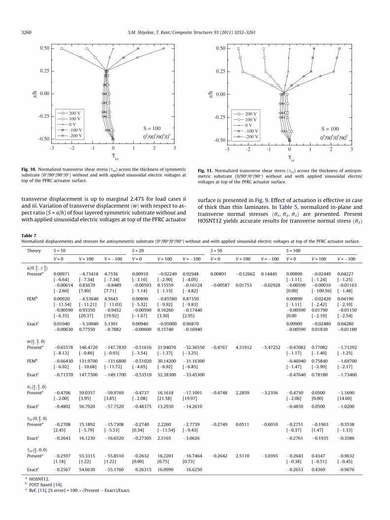
Fig. 10. Normalized transverse shear stress (sxz) across the thickness of symmetricsubstrate (0�/90�/90�/0�) without and with applied sinusoidal electric voltages attop of the PFRC actuator surface.
-3 -2 -1 0 1 2 3
-0.50
-0.25
0.00
0.25
0.50
S = 100
00/900/00/900
200 V 100 V 0 V -100 V -200 V
z/h
τxz
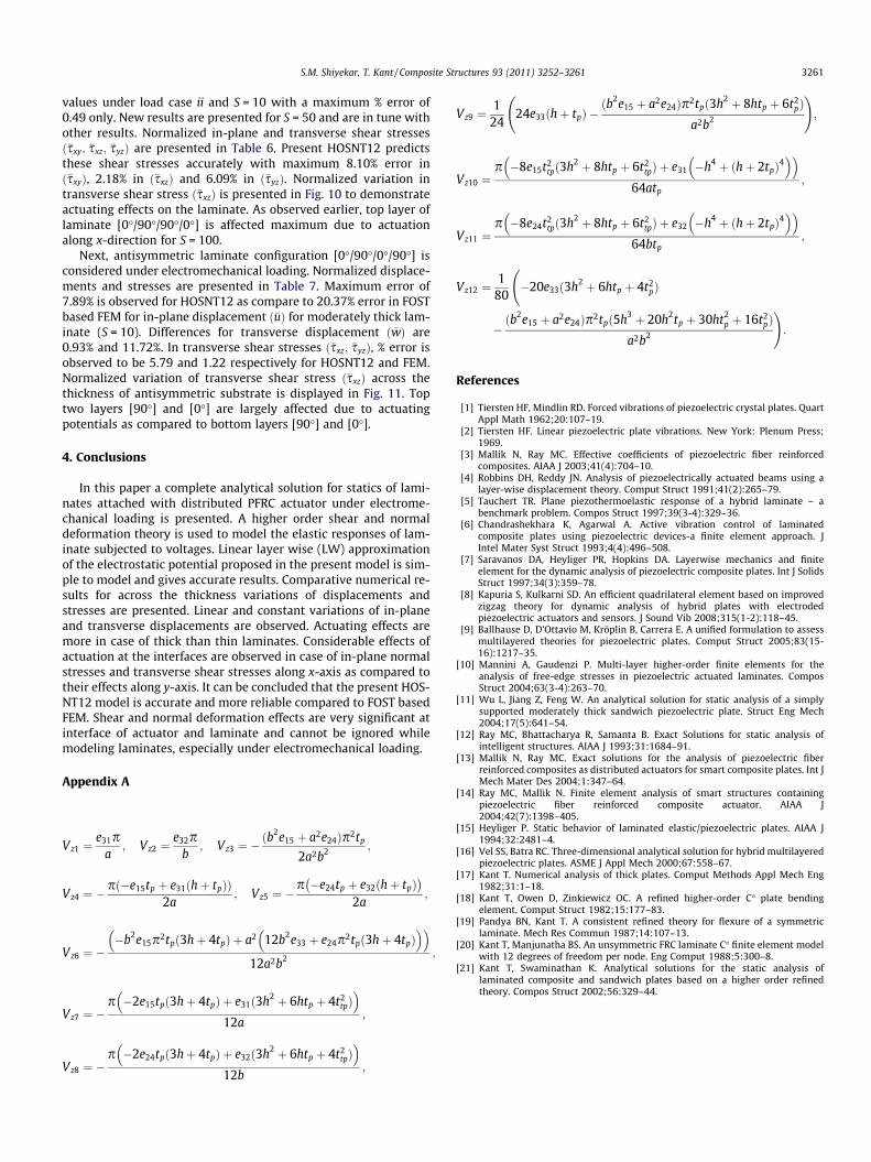
Fig. 11. Normalized transverse shear stress (sxz) across the thickness of antisym-metric substrate (0/90�/0�/90�) without and with applied sinusoidal electricvoltages at top of the PFRC actuator surface.
3260 S.M. Shiyekar, T. Kant / Composite Structures 93 (2011) 3252–3261
transverse displacement is up to marginal 2.47% for load cases iiand iii. Variation of transverse displacement ð�wÞwith respect to as-pect ratio (S = a/h) of four layered symmetric substrate without andwith applied sinusoidal electric voltages at top of the PFRC actuator
Table 7Normalized displacements and stresses for antisymmetric substrate (0�/90�/0�/90�) witho
Theory S = 10 S = 20
V = 0 V = 100 V = �100 V = 0 V = 100 V = �10
�u 0; b2 ;� h
2
� �Presenta 0.00971 �4.73418 4.7536 0.00910 �0.92249 0.9294
[�6.64] [�7.34] [�7.34] [�3.16] [�2.90] [�4.05�0.00614 0.83670 �0.8489 �0.00593 0.15559 �0.161[�2.60] [7.89] [7.71] [�1.14] [�1.15] [�4.82
FEMb 0.00920 �4.53640 4.5643 0.00890 �0.85580 0.8735[�11.54] [�11.21] [�11.03] [�5.32] [�9.92] [�9.83�0.00590 0.93350 �0.9452 �0.00590 0.16260 �0.174[�6.35] [20.37] [19.92] [�1.67] [3.30] [2.95]
Exactc 0.01040 �5.10940 5.1301 0.00940 �0.95000 0.9687�0.00630 0.77550 �0.7882 �0.00600 0.15740 �0.169
�w a2 ;
b2 ; 0
� �Presenta �0.65578 146.4720 �147.7830 �0.51616 31.94070 �32.36
[�8.12] [�0.86] [�0.93] [�3.54] [�1.37] [�3.25
FEMb �0.66430 131.9700 �131.6800 �0.51020 30.14200 �31.16[�6.92] [�10.68] [�11.72] [�4.65] [�6.92] [�6.85
Exactc �0.71370 147.7500 �149.1700 �0.53510 32.38300 �33.45
�rza2 ;
b2 ;0
� �Presenta �0.4706 59.0357 �59.9769 �0.4737 16.1618 �17.10
[�2.00] [3.95] [3.85] [�2.08] [21.58] [19.97]
Exactc �0.4802 56.7920 �57.7520 �0.48375 13.2930 �14.26
�sxz 0; b2 ;0
� �Presenta �0.2708 15.1892 �15.7308 �0.2740 2.2260 �2.773
[2.45] [�5.79] [�5.53] [0.34] [�11.54] [�9.43
Exactc �0.2643 16.1230 �16.6520 �0.27305 2.5165 �3.062
�syza2 ;0;0� �
Presenta �0.2597 55.3315 �55.8510 �0.2632 16.2201 �16.74[1.18] [1.22] [1.22] [0.00] [0.75] [0.73]
Exactc �0.2567 54.6630 �55.1760 �0.26315 16.0990 �16.62
a HOSNT12.b FOST based [14].c Ref. [13], [% error] = 100 � (Present � Exact)/Exact.
surface is presented in Fig. 9. Effect of actuation is effective in caseof thick than thin laminates. In Table 5, normalized in-plane andtransverse normal stresses ð�rx; �ry; �rzÞ are presented. PresentHOSNT12 yields accurate results for transverse normal stress ð�rzÞ
ut and with applied sinusoidal electric voltages at top of the PFRC actuator surface.
S = 50 S = 100
0 V = 0 V = 100 V = �100 V = 0 V = 100 V = �100
8 0.00891 �0.12662 0.14445 0.00890 �0.02449 0.04227] [�1.11] [�1.24] [�1.25]24 �0.00587 0.01753 �0.02928 �0.00590 �0.00010 �0.01163] [0.00] [�100.56] [�1.48]
0 0.00890 �0.02420 0.04190] [�1.11] [�2.42] [�2.10]40 �0.00590 0.01790 �0.01150
[0.00 [�2.19] [�2.54]
0 0.00900 �0.02480 0.0428040 �0.00590 0.01830 �0.01180
550 �0.4767 4.51912 �5.47252 �0.47082 0.77082 �1.71292] [�1.17] [�1.40] [�1.25]
300 �0.46940 0.75840 �1.69700] [�1.47] [�2.99] [�2.17]
300 �0.47640 0.78180 �1.73460
91 �0.4748 2.2859 �3.2356 �0.4750 0.0500 �1.1690[�2.06] [0.00] [14.60]
10 �0.4850 0.0500 �1.0200
9 �0.2749 0.0511 �0.6010 �0.2751 �0.1963 �0.3538] [�0.37] [1.47] [�1.33]
6 �0.2761 �0.1935 �0.3586
64 �0.2642 2.5110 �3.0393 �0.2643 0.4347 �0.9632[�0.38] [�0.51] [�0.45]
50 �0.2653 0.4369 �0.9676
S.M. Shiyekar, T. Kant / Composite Structures 93 (2011) 3252–3261 3261
values under load case ii and S = 10 with a maximum % error of0.49 only. New results are presented for S = 50 and are in tune withother results. Normalized in-plane and transverse shear stressesð�sxy; �sxz; �syzÞ are presented in Table 6. Present HOSNT12 predictsthese shear stresses accurately with maximum 8.10% error inð�sxyÞ, 2.18% in ð�sxzÞ and 6.09% in ð�syzÞ. Normalized variation intransverse shear stress ð�sxzÞ is presented in Fig. 10 to demonstrateactuating effects on the laminate. As observed earlier, top layer oflaminate [0�/90�/90�/0�] is affected maximum due to actuationalong x-direction for S = 100.
Next, antisymmetric laminate configuration [0�/90�/0�/90�] isconsidered under electromechanical loading. Normalized displace-ments and stresses are presented in Table 7. Maximum error of7.89% is observed for HOSNT12 as compare to 20.37% error in FOSTbased FEM for in-plane displacement ð�uÞ for moderately thick lam-inate (S = 10). Differences for transverse displacement ð �wÞ are0.93% and 11.72%. In transverse shear stresses ð�sxz; �syzÞ, % error isobserved to be 5.79 and 1.22 respectively for HOSNT12 and FEM.Normalized variation of transverse shear stress ð�sxzÞ across thethickness of antisymmetric substrate is displayed in Fig. 11. Toptwo layers [90�] and [0�] are largely affected due to actuatingpotentials as compared to bottom layers [90�] and [0�].
4. Conclusions
In this paper a complete analytical solution for statics of lami-nates attached with distributed PFRC actuator under electrome-chanical loading is presented. A higher order shear and normaldeformation theory is used to model the elastic responses of lam-inate subjected to voltages. Linear layer wise (LW) approximationof the electrostatic potential proposed in the present model is sim-ple to model and gives accurate results. Comparative numerical re-sults for across the thickness variations of displacements andstresses are presented. Linear and constant variations of in-planeand transverse displacements are observed. Actuating effects aremore in case of thick than thin laminates. Considerable effects ofactuation at the interfaces are observed in case of in-plane normalstresses and transverse shear stresses along x-axis as compared totheir effects along y-axis. It can be concluded that the present HOS-NT12 model is accurate and more reliable compared to FOST basedFEM. Shear and normal deformation effects are very significant atinterface of actuator and laminate and cannot be ignored whilemodeling laminates, especially under electromechanical loading.
Appendix A
Vz1 ¼e31p
a; Vz2 ¼
e32pb
; Vz3 ¼ �ðb2e15 þ a2e24Þp2tp
2a2b2 ;
Vz4 ¼ �pð�e15tp þ e31ðhþ tpÞÞ
2a; Vz5 ¼ �
p �e24tp þ e32ðhþ tpÞ� �
2a;
Vz6 ¼ ��b2e15p2tpð3hþ 4tpÞ þ a2 12b2e33 þ e24p2tpð3hþ 4tpÞ
� �� �12a2b2 ;
Vz7 ¼ �p �2e15tpð3hþ 4tpÞ þ e31ð3h2 þ 6htp þ 4t2
tp� �
12a;
Vz8 ¼ �p �2e24tpð3hþ 4tpÞ þ e32ð3h2 þ 6htp þ 4t2
tp� �
12b;
Vz9 ¼1
2424e33ðhþ tpÞ �
ðb2e15 þ a2e24Þp2tpð3h2 þ 8htp þ 6t2pÞ
a2b2
!;
Vz10 ¼p �8e15t2
tpð3h2 þ 8htp þ 6t2tpÞ þ e31 �h4 þ ðhþ 2tpÞ4
� �� �64atp
;
Vz11 ¼p �8e24t2
tpð3h2 þ 8htp þ 6t2tpÞ þ e32 �h4 þ ðhþ 2tpÞ4
� �� �64btp
;
Vz12 ¼1
80
�20e33ð3h2 þ 6htp þ 4t2
pÞ
�ðb2e15 þ a2e24Þp2tpð5h3 þ 20h2tp þ 30ht2
p þ 16t2pÞ
a2b2
!:
References
[1] Tiersten HF, Mindlin RD. Forced vibrations of piezoelectric crystal plates. QuartAppl Math 1962;20:107–19.
[2] Tiersten HF. Linear piezoelectric plate vibrations. New York: Plenum Press;1969.
[3] Mallik N, Ray MC. Effective coefficients of piezoelectric fiber reinforcedcomposites. AIAA J 2003;41(4):704–10.
[4] Robbins DH, Reddy JN. Analysis of piezoelectrically actuated beams using alayer-wise displacement theory. Comput Struct 1991;41(2):265–79.
[5] Tauchert TR. Plane piezothermoelastic response of a hybrid laminate – abenchmark problem. Compos Struct 1997;39(3-4):329–36.
[6] Chandrashekhara K, Agarwal A. Active vibration control of laminatedcomposite plates using piezoelectric devices-a finite element approach. JIntel Mater Syst Struct 1993;4(4):496–508.
[7] Saravanos DA, Heyliger PR, Hopkins DA. Layerwise mechanics and finiteelement for the dynamic analysis of piezoelectric composite plates. Int J SolidsStruct 1997;34(3):359–78.
[8] Kapuria S, Kulkarni SD. An efficient quadrilateral element based on improvedzigzag theory for dynamic analysis of hybrid plates with electrodedpiezoelectric actuators and sensors. J Sound Vib 2008;315(1-2):118–45.
[9] Ballhause D, D’Ottavio M, Kröplin B, Carrera E. A unified formulation to assessmultilayered theories for piezoelectric plates. Comput Struct 2005;83(15-16):1217–35.
[10] Mannini A, Gaudenzi P. Multi-layer higher-order finite elements for theanalysis of free-edge stresses in piezoelectric actuated laminates. ComposStruct 2004;63(3-4):263–70.
[11] Wu L, Jiang Z, Feng W. An analytical solution for static analysis of a simplysupported moderately thick sandwich piezoelectric plate. Struct Eng Mech2004;17(5):641–54.
[12] Ray MC, Bhattacharya R, Samanta B. Exact Solutions for static analysis ofintelligent structures. AIAA J 1993;31:1684–91.
[13] Mallik N, Ray MC. Exact solutions for the analysis of piezoelectric fiberreinforced composites as distributed actuators for smart composite plates. Int JMech Mater Des 2004;1:347–64.
[14] Ray MC, Mallik N. Finite element analysis of smart structures containingpiezoelectric fiber reinforced composite actuator. AIAA J2004;42(7):1398–405.
[15] Heyliger P. Static behavior of laminated elastic/piezoelectric plates. AIAA J1994;32:2481–4.
[16] Vel SS, Batra RC. Three-dimensional analytical solution for hybrid multilayeredpiezoelectric plates. ASME J Appl Mech 2000;67:558–67.
[17] Kant T. Numerical analysis of thick plates. Comput Methods Appl Mech Eng1982;31:1–18.
[18] Kant T, Owen D, Zinkiewicz OC. A refined higher-order C� plate bendingelement. Comput Struct 1982;15:177–83.
[19] Pandya BN, Kant T. A consistent refined theory for flexure of a symmetriclaminate. Mech Res Commun 1987;14:107–13.
[20] Kant T, Manjunatha BS. An unsymmetric FRC laminate C� finite element modelwith 12 degrees of freedom per node. Eng Comput 1988;5:300–8.
[21] Kant T, Swaminathan K. Analytical solutions for the static analysis oflaminated composite and sandwich plates based on a higher order refinedtheory. Compos Struct 2002;56:329–44.