pierre bosland 23 rd of june 2015 ess cavities interfaces
TRANSCRIPT

Pierre Bosland
23RD OF JUNE 2015
ESS CAVITIES INTERFACES
223RD OF JUNE 2015
Cavities lifecycle
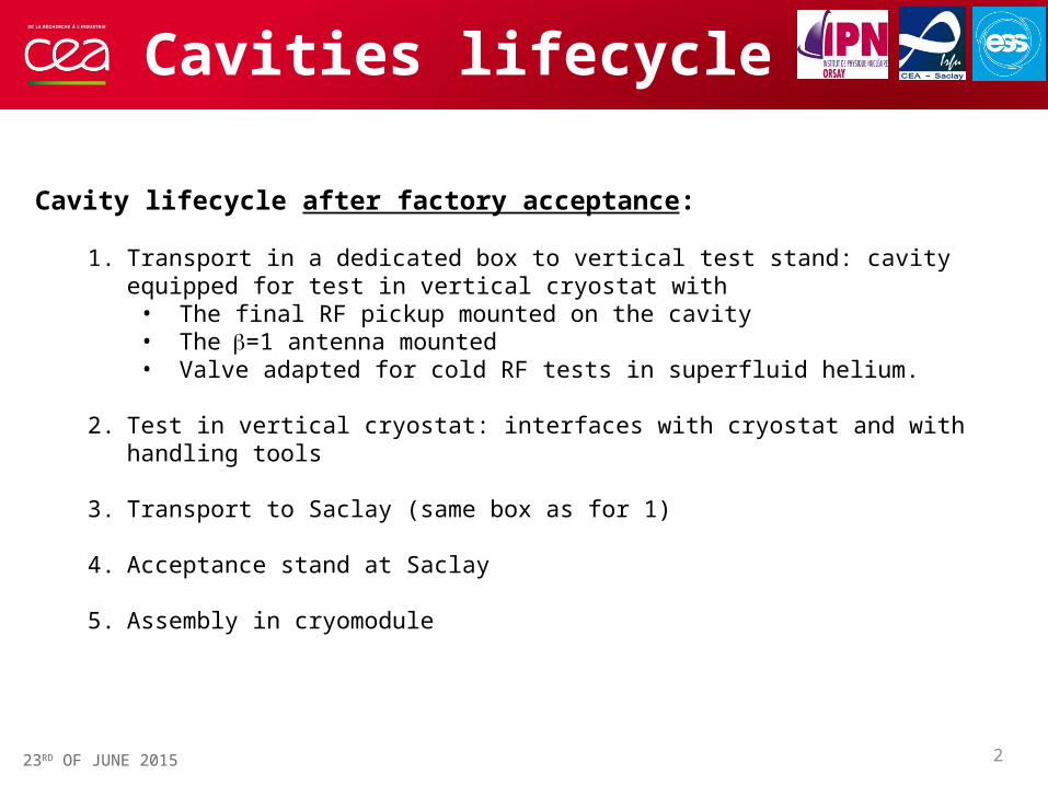
Cavity lifecycle after factory acceptance:
1. Transport in a dedicated box to vertical test stand: cavity equipped for test in vertical cryostat with
• The final RF pickup mounted on the cavity• The b=1 antenna mounted• Valve adapted for cold RF tests in superfluid helium.
2. Test in vertical cryostat: interfaces with cryostat and with handling tools
3. Transport to Saclay (same box as for 1)
4. Acceptance stand at Saclay
5. Assembly in cryomodule

323RD OF JUNE 2015

423RD OF JUNE 2015
The cavity production is under the full responsibility of the LASA/STFC.
The factory acceptance criteria are established by LASA/STFC in agreement with ESS and the factory acceptance are under the responsibility of LASA/STFC.
The RFA (Ready For Assembly) acceptance criteria are established in a common agreement between CEA and ESS/LASA/STFC. The RFA acceptance tests (and controls: QC ?) will be performed by CEA.
The RFA acceptance of each cavity before assembly will be under the responsibility of ESS.
The transfer of the cavities ownership to ESS is effective after the RFA acceptance of the cavities.
Non conformities will be managed following a policy on which each party shall agree upon.
Acceptance and transfer of ownership PROPOSAL
Date for criteria agreement to be defined now!

523RD OF JUNE 2015
Cavities interfaces & requirements
Cavity physical interfaces before assembly in the cryomodule:
1. Beam flanges (closed by a blank flange + valve)
2. Power coupler flange (closed by a blank flange + b=1 antenna)
3. Pickup mounted on the cavity: RF pickup connector
4. Support of the cavity in the cryomodule (interfaces for rods fixations)
5. Magnetic shielding
6. Cold tuning system
7. Handling tools
8. Alignment tools interfaces
9. Cryogenic pipes: flange of the cooling helium pipe (to be suppressed by a
welded tube or not ?) + welded tube to the 2 phases tube above the
helium tank.

623RD OF JUNE 2015
BEAM FLANGES & « TUNER RING »
Vacuum tightness Alignement tools and reference Blocking fixtures

723RD OF JUNE 2015
POWER COUPLER PORT
Vacuum tigthness External coupling Qext (height & position %
cell iris)
54 56 58 60 62 64 66 683.0E+05
4.0E+05
5.0E+05
6.0E+05
7.0E+05
8.0E+05
9.0E+05
1.0E+06Qext
high beta
medium beta
distance axis-antenna tip D (in mm)
The Qext sensitivity calculated with HFSS gives:•Medium beta cavity: D=61,26mm for Qext =7,5e5•High beta cavity: D=64,41mm for Qext =7,6e5
D
47
70
Rext = 50
Rint = 21.74
35
Rcone (without filet) = 28
Hcone = 50
Rfilet-tip = 3
Rfilet-base = 8

823RD OF JUNE 2015
PICK-UP ANTENNA
RF connector at 90°
Cavity beam tube
Alu gasket
Pick-up antenna
Pick-up port
• 30 units ordered • Designed to transmit 30 dBm
Transmitted power required by LLRF: Pt > 20 dBm at nominal gradient
923RD OF JUNE 2015
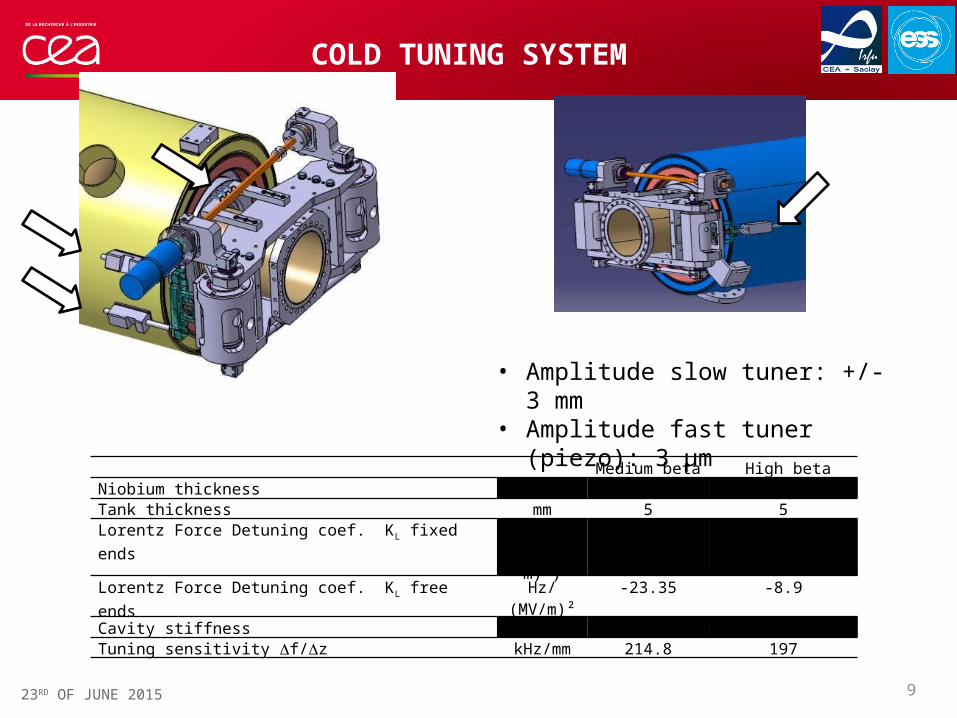
COLD TUNING SYSTEM
• Amplitude slow tuner: +/- 3 mm• Amplitude fast tuner (piezo): 3 µm
Medium beta High betaNiobium thickness mm 4 3.6Tank thickness mm 5 5Lorentz Force Detuning coef. KL fixed ends Hz/(MV/
m)²)- 0.735 -0.36
Lorentz Force Detuning coef. KL free ends Hz/(MV/m)²
-23.35 -8.9
Cavity stiffness kN/mm 1.286 2.59Tuning sensitivity Df/Dz kHz/mm 214.8 197

1023RD OF JUNE 2015
MULTILAYER INSULATION
- Between helium tank and magnetic shield
- Detailed design not yet finalized

1123RD OF JUNE 2015
MAGNETIC SHIELDING

1223RD OF JUNE 2015
CAVITY SUPPORTING SYSTEM IN THE CRYOMODULE

1323RD OF JUNE 2015
HELIUM SUPPLY AND RETURN
He return (welded)
He supply
• Pressure test to be established

1423RD OF JUNE 2015
CAVITY HANDLING TOOLS
Transport, assembly and rotation
Unpacking and handling horizontally
Lifting
Horizontal support and rotation for visual inspection
Wheels

1523RD OF JUNE 2015
Cavity functional interface requirements (see DOORS):
1. F = 704,42 MHz at 2K
2. Acceptance F = XXX at the acceptance conditions to be defined
3. Eacc= 16,7MV/m (Mb) Eacc= 19,9MV/m (Hb) <= cryomodule nominal
4. Dangerous HOM frequencies: 5MHz away from integer multiples of the beam bunching frequencies
(n*352,21MHz)
5. Power coupler Qext : 5,9E5 < M < 8 5 b E & 6,6E5 < H < 7,6 5b E - see technical notes for Mb and
Hb cavity couplers.
6. R/Q = 395 at bopt => Pmax close to 900kW for medium beta cavities to get the needed voltage . Need
of a high R/Q value!
7. Pickup antenna Qt – no issue - requirement 20dBm at the pickup connector at the nominal field
8. Lorentz force detuning: 3µm max deformation with piezo stacks
9. PS = 1,04barg + V max LHe = 48 liters => article 3.3 according to PED
10. …
SOME REQUIREMENTS L4