picture archiving and communication in radiology: an american perspective
TRANSCRIPT
Picture Archiving and Communication in Radiology: An American Perspective
Seong K. Mun, Steve Horii, and Harold Benson
A comprehensive image management and communi- cation (IMAC) network has been installed at Georgetown University Hospital (GUH) for an extensive clinical eval- uation. The network is based on the AT&T CommView system and includes interfaces to 12 imaging devices, 15 workstations (inside and outside the radiology de- partment), a teleradiology link to an imaging center, an optical jukebox, anda number of advanced image display and processing systems. Two years of clinical expe¡ with the network enable us to develop a plan for future activities from an American perspective. The IMAC project is not jus ta technical challenge, but also a professional, organizational, and administrative one, Several obstacles remain, but they are gradually being overcome as more cost-effective and streamlined tech- nologies become available and as users and developers gain more operational experience in managing diagnostic images in an electronic environment. Copyright �9 1991 by W.B. Saunders Company
KEY WORDS: PACS, IMAC, diagnostic imaging, data management.
T HE NEW IMAGING technologies have given the radiologist a powerful set of new
diagnostic tools; however, the quality of radiology service has not undergone similar revolutionary improvements during the decade. Indeed, the use of many imaging modalities has imposed addi- tional difliculties in managing films and data. New imaging systems have created a number of difficulties in managing radiology images and in- formation because: (1) they are often produced in physically distant locations, (2) images are presented in varying film formats, (3) radiology service is highly subspecialized and there is a greater need to review multimodality images, and (4) within large and complex medical care facil- ities there are an increasing number of competing demands for radiological images.
Ir is generally accepted that management of radiology images can be improved by using some computer-based image system, but opinions vary. What type of approach is desirable? The possible solutions will depend on such factors as the nature of radiology service, the types of images, and the clinical worktoad. Use of computer-based image management is becoming a major challenge and is soon expected to generate great interest.
As the technical problems are being addressed, the impact of IMAC technology to the radiology service in the context of both patient care and the professional role of diagnosticians is becom- ing a major area of debate. IMAC is not a reve- nue-producing technology, and many of the ben- efits are intangible items. The use of IMAC will have a profound and pervasive impact on patient care activities throughout the hospital. We de- scribe an American perspective of the imple- mentation issues of IMAC technology from an institutional and organizational viewpoint.
DESCRIPTION OF THE COMPREHENSlVE IMAC NETWORK AT GEORGETOWN
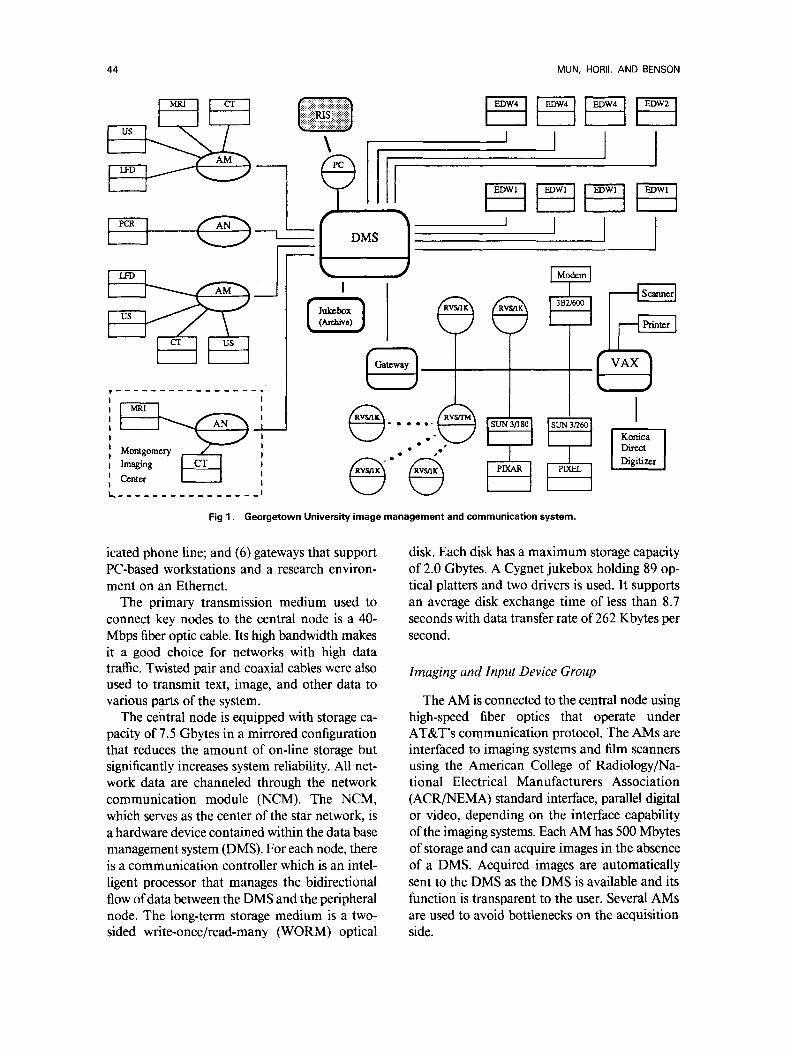
Georgetown University Hospital (GUH) has installed a comprehensive IMAC system as a part of a digital imaging network system (DINS) demonstration and evaluation program. This section desc¡ the IMACS based on the AT&T CommView (Shelton, CT) network. This section is divided into tire general sections: (1) com- munication and data base system, (2) image gen- eration, (3) workstation groups, (4) teleradiology application, and (5) the research and develop- ment environment. Figure 1 shows the general system configuration as of December 1989.
Communication and Data Base System
The primary network topology used in the CommView system is the star based on 40 Mbps optical fiber. The central data management sys- rem (DMS) is connected to (1) acquisition mod- ules (AM) which collect images from many im- aging devices; (2) high-speed workstations located throughout the hospital; (3) an archival jukebox of 89 optical platters; (4) a radiology information system through a PC; (5) an outpatient imaging center, located 15 miles away, over a T-1.5 ded-
From the Department of Radiology, Georgetown University Hospital, Washington, DC.
Address reprint requests to Seong K. Mun, MD, PhD, De- partment of Radiology, Georgetown University Hospital, Washington, DC 20007.
Copyright �9 1991 by W.B. Saunders Company 0897-1889/91/0404-0110503.00/0
Joumal of Digital Imaging, Vol 4, No 4, Suppl 1 (November), 1991 : pp 43-53 43
44 MUN, HORII, AND BENSON
Montgomery Imaging Center
L~ . . . . . . . . . . . . . . . .
\
I I DMS
F~ I i i I
) J I I
~. F e"~ P
f I
Direct Digitizer
Fig 1. Georgetown University image management and communication system.
icated phone line; and (6) gateways that support PC-based workstations anda research environ- ment on an Ethernet.
The primary transmission medium used to connect key nodes to the central node is a 40- Mbps fiber optic cable. Its high bandwidth makes it a good choice for networks with high data traffic. Twisted pair and coaxial cables were also used to transmit text, image, and other data to various parts of the system.
The central node is equipped with storage ca- pacity of 7.5 Gbytes in a mirrored configuration that reduces the amount of on-line storage but significantly increases system reliability. All net- work data are channeled through the network communication module (NCM). The NCM, which serves as the center of the star network, is a hardware device contained within the data base management system (DMS). For each node, there is a communication controller which is an intel- ligent processor that manages the bidirectional flow of data between the DMS and the peripheral node. The long-term storage medium is a two- sided write-once/read-many (WORM) optical
disk. Each disk has a maximum storage capacity of 2.0 Gbytes. A Cygnet jukebox holding 89 op- tical platters and two drivers is used. It supports an average disk exchange time of less than 8.7 seconds with data transfer rate of 262 Kbytes per second.
Imaging and Input Device Group
The AM is connected to the central node using high-speed fiber optics that operate under AT&T's communication protocol. The AMs are interfaced to imaging systems and film scanners using the American College of Radiology/Na- tional Electrical Manufacturers Association (ACR/NEMA) standard interface, parallel digital or video, depending on the interface capability of the imaging systems. Each AM has 500 Mbytes of storage and can acquire images in the absence of a DMS. Acquired images are automatically sent to the DMS as the DMS is available and its function is transparent to the user. Several AMs ate used to avoid bottlenecks on the acquisition side.
AMERICAN PACS 45
Six imaging systems (a Siemens MRI [Siemens Medical Systems, Iselin, NJ]; two GE 9800 com- puted tomography [CT] scans, fluoroscopy, and ultrasound) are supported by two AMs; Philips computed radiography (PCR, Philips, Shelton, CT) which is being installed, is supported by a separate AM. Two laser film scanners, Konica and Dupont, have DR11W interface; PCR has ACR/NEMA interface functionality based on DR11W hardware. ACR/NEMA interfaces are being installed for magnetic resonance imaging (MRI) and CT imaging systems. Ultrasound im- agers are connected through video interface. The laser film digitizers (LFD) generate 2000 X 2500 X 12 bits for DuPont and 2000 X 2500 X 10 bits for Konica in digitizing chest films and the PCR generates 2000 X 2500 X 10 bits per image.
Workstation Group
The IMAC network based on AT&T's CommView system supports three categories of workstation: (1) enhanced display workstations (EDW), (2) results viewing stations (RVS), and (3) special workstations such as SUN3 and 4, SUN SPARC, PIXEL, and PIXAR. The EDW workstations are supported by 40 Mbps optical ¡ links and EDWs can be configurated with four, or two screens ora single screen in portrait mode. Each EDW has 360 or 500 Mbytes of stor- age and can be upgraded to 760 Mbytes. Primary user interface is a set of dedicated function keys and dual-track balls.
The image data matrix size is 2K X 2.5K X 12 bits for chest images on the network. The work- station either displays 1K X 1.2K images or a full data set can be accessed using the pan or magnification features. The latest upgrade enables us to display 80 MRI or CT images on four screens in less than 20 seconds. A diagnosis can be entered at the workstation through a key board. The user interface to the workstations is analogous to the physical patient folder. Patient folders can be requested, and multimodality im- ages or text can be pulled from the folder for display. Multimodality Images can be moved from screen to screen, zoomed, rotated, panned, or flipped. Window level and width can be changed, and the lookup tables can be modified in real time.
The RVSs are PC-based workstations that can be supported either on Ethernet (Xerox, Sun Mi-
crosystems, Mountain View, CA) or over a 19.2K modem. Each EDW and RVS has a separate data terminal with a keyboard and CRT. An EDW has a number ofdedicated function keys for each operation. The GUH system provides multi- screen high-resolution workstations to the fol- lowing subspecialty areas: neuroradiology, ab- dominal imaging, ultrasound imaging, and general radiography. The following services with single-screen EDW are on the network: radiation oncology, emergency room (ER), nuclear medi- cine (NM), cardiovascular surgical intensive care unit (CVSICU), intensive care nursery (ICN), and pediatric intensive care unit (PICU). Additional services with RVS that will be on the network are cardiac radiology, oncology, neurosurgery, and other sites.
Teleradiology Group
The GUH Radiology Department operated an outpatient imaging center in Rockville, Mary- land. Montgomery Imaging Center (MIC), lo- cated 13 miles north of GUH, has a complete radiology service, including CT and MRI. All the neuroradiology service for CT and MRI is pro- vided at GUH. Siemens 1.0-T MRI and Siemens CT were connected (video) to an AM, and the AM was connected to the GUH DMS over a T- 1 line that costs $750 per month. The T-1 line has a transmission capability of 1.5 Mbps. Images transmitted to the GUH workstation appeared within a few seconds. The teleradiology service was terminated in November 1989 because there was no longer any clinical relationship with the center.
Research Environment
A research environment consisting of a num- ber of advanced image processing and display devices has been developed to test basic concepts in IMAC in the absence of daily clinical opera- tional requirements. The developmental network is based on Ethernet and it is connected to the CommView network through a gateway. Image and information can be exchanged between the clinical and developmental environment. The network has several sections: image processing, network research, and a Konica facility.
The image processing section is supported by SUN computers (PIXEL and PIXAR) and is pri- marily concerned with data compression, work-
46 MUN, HORII, AND BENSON
station, and image handling issues. The network research section (outfitted with AT&T PC386 and a shared SUN) concentrates on RIS interface and network modeling and validation. A Konica di- rect digitizer (based on Konica's phosphor plate) anda Konica laser printer are under evaluation in the research environment.
CLINICAL SERVICES
IMAC technology has been implemented and tested in a number of divisions, services, and ap- plications at GUH. These include neuroradiol- ogy, abdominal imaging, general radiology, nu- clear medicine, the pediatric and neonatology intensive care units, radiation medicine, and teleradiology (both to auxiliary clinics anda ra- diologist's home).
Neuroradiology The network has been well received by neu-
roradiologists except for the fact that many of the newer MRI studies yield more than 80 images (100 to 120), so that ir is no longer possible to view an entire examination at once. To date they have been the only group to request that future workstation designs consider six to eight display monitors.
Much of the evaluation consisted of monitor- ing performance of primary reading from the workstation as compared with film. The MIC studies, though read on the EGDW, were also ¡ and the films were sent to Georgetown. The neuroradiologists could then review the films to be sure that they had not missed any findings. After some months of this procedure, with the discovery that no findings had been missed on the workstation reading, most of the film reviews were skipped. In addition, discussions and inter- views with the neuroradiologists were held to as- sess their reactions to the system. They were gen- erally positive, although all ofthem thought that speed could be improved. Preloading their work- station with current images reduced much of the complaint about slow image presentation.
For the neuroradiology division, the DINS proved an acceptable clinical tool. In both the teleradiology application and the local reading use, the system proved to save time. In the former use, this resulted from viewing the images on the same day they were obtained, in some instances within an hour oftheir being acquired ifdecisions
about the completeness of a study were needed. In the latter use, the value has been in retrieval of comparison cases. This is also p¡ a timesaving feature because the neuroradiology reading room is two floors above radiology.
Abdominal Imaging
The Abdominal Imaging Division of the GUH Department of Radiology consists of 5 radiolo- gists and is responsible for performing and inter- preting images related to gastrointestinal (GI), genitourinary (GU), biliary tract, and certain in- terventional procedures. In addition, the division is responsible for most thoracic CT studies. The imaging techniques used by the division include plain radiography (with and without contrast agents), analog and digital fluoroscopy, CT, MRI, and ultrasound. Of the equipment used by the Abdominal Imaging Department, both CT ma- chines, the MRI system, 4 ultrasound units, and 1 fluoroscopic system (in the biliary lithotripsy suite) are interfaced to the DINS. The film digi- tizers are also available for input of plain films.
The workstation in the division reading room is one of the most heavily used. The major change (from occasional to routine use) was the result of the changes provided in release 3 of the software. Most important was the ability at the workstation to restore cases to the data base from the optical archive. This automatic de-archive proved a very attractive feature and resulted in very heavy use of the system by the radiology residents and fel- lows. They discovered very quickly that ret¡ cases on the workstation was far faster than at- tempting to obtain the films from the file room. A typical reduction in time was from 15 minutes for the file room (if the films could be found) to 5 minutes at the workstation. The addition of the high-speed display and large local storage afforded by the "turbo" upgrade increased use even further because these features reduced the delay in dis- playing images and eliminated the problem of a full local disk.
The increased capacity and speed, coupled with connection of the fourth ultrasound machine to the DINS, led the ultrasound section to begin primary reading at the workstation. The local disk capacity is now large enough to store more than a full day ofultrasound cases. The worklist feature also simplifies retrieval ofcases, and to some ex-

AMERICAN PACS 47
tent, automatically routes ultrasound examina- tions to the workstation. This eliminates the task of having to load the workstation manually, muchas one has to load a film alternator. The ultrasound section is still producing film, but the films are being used a sa check on display per- formance. Thus far, pathology was displayed equally well on the workstation and on film. Reading is done on all ultrasound cases acquired by the DINS; this excludes approximately 3 to 5 portable examinations per day of a total of 13 to 30 daily studies.
The CT section is using the workstation pri- marily to retrieve previous cases for comparison and occasionally for review with referring phy- sicians. Primary reading is inhibited at this time by the fact that the images are video frame grabbed. Although the resolution is considered adequate, the lack of full digital data prevents window and level adjustments through the entire range of tissue attenuation values.
A study of the suitability of digitized film and digital fluoroscopy for endoscopic retrograde cholangiopancreatography (ERCP) was per- formed by the abdominal radiology division, and the results were reported at the 1989 Radiological Society of North America (RSNA) Annual Meeting. Fifty proven cases were taken randomly from the files, and the spot films and photospots (the images photographed from the image inten- sifier output) were digitized on the DuPont LFD. The images were stored in routine fashion on op- tical and magnetic media. A radiologist then in- terpreted these studies at the workstation without knowledge of the original reading. Hejudged both diagnostic quality as well as image preference (film or CRT image). The results showed no sig- nificant differences between the o¡ films and their CRT-displayed and CRT-interpreted coun- terparts in either diagnostic quality or user pref- erence. As a result of this study, an ongoing pro- spective study has been undertaken to examine digital fluoroscopic images of the GI tract viewed on the workstation as compared with photospot films of the same areas.
General Radiology
The general radiology division (consisting of musculoskeletal and chest radiology) was the last of the radiology divisions to have an EGDW in- stalled. The bulk of the work done in general ra-
diology utilizes screen/film exposures for image generation. On the basis of departmentwide workload, the largest number of plain films are interpreted by the general radiologists. Some musculoskeletal MRI and CT is also read, as is most of the ER work.
The gray scale resolution necessary for reading from the CRT displays has been studied. A s a result, we undertook a study of the number of bits of gray scale required for locating catheters and evaluating pulmonary vasculature on adult portable chest films. A thoracic radiologist se- lected routine portable chest cases which dem- onstrated both catheters that were easy and cath- eters that were difficult to locate and both those with and without evidence of pulmonary vascular congestion. A set ofthese films were then digitized and from each digitized image 6 more were made with the full 12, then 9, 8, 7, 6, and 5 bits of gray scale to represent the range of densities in the image. Bit reduction was achieved by truncating the pixel bits with dithering of the low-order bit based on the highest order bit to be truncated. The resulting image sets were reviewed indepen- dently by two radiologists. They were not in- formed of the number of bits in the image they were viewing until after they had rated the image as to visibility of catheters and whether or not the pulmonary vasculature could be evaluated. The order of images within a set was also ran- domized so that there was no general trend (eg, from fewest to most bits). The results were that a mŸ of 6 to 7 bits of gray scale were needed to see catheters well anda minimum of 5 to 6 bits were required to evaluate pulmonary vessels. Overall, a minimum of 7 bits was nec- essary to visualize all findings. There were no sig- nificant differences between the two observers in the number of bits required. These results were reported at the 1989 SNA Annual Meeting. The study should be considered preliminary because it was conducted with a few images, a few readers, and portable chest films. These films may not have the same display requirements as conven- tional chest images because they are frequently ofa quality lower than that ofconventional chest films. In general, this is because the patients are very ill and cannot stand erect or fully expand their lungs.
In general radiography, much ofwhat happens in the next 6 months is tied to installation of the
48 MUN, HORII, AND BI=NSON
CR system. The main thrust of the work will be to install the CR and begin evaluation for our u s e s .
NM
Because NM is located in a different building and three floors up from radiology, ir is very time- consuming for NM physicians to come to ra- diology to retrieve or review cases. Because many nuclear medicine studies are functional, corre- lation with the anatomic imaging provided by other techniques is necessary for proper diag- nostic interpretation. The NM division is the heaviest intradepartmental user of correlation studies, and its use of the workstation reflects these needs.
Because NM is not connected to the DINS as an image source, we have not performed studies aimed at interpreting nuclear medical images on the workstation. We have conducted an ongoing process of interviews with the NM physicians and have involved them in our planning and feedback to the DINS vendor.
PICU
The PICU was among the early sites considered for a workstation Iocation. The choice was based on the combination of a relatively small number of beds coupled with an urgent demand for film availability when portable films are made. The nature of operation of the PICU is one of a very busy service for a few patients. For this reason, the physicians who work in the unit are reluctant to leave for any length of time. As is true oflCU population, the patients are very sick, and con- stant attention is a must. This is particularly true ofpediatric patients in whom the changes ofclin- ical status often occur much more rapidly than in adults. The department had considered in- stalling an alternator for films on the floor, but that would have required radiology personnel to load and unload ir as well as the presence of a radiologist to review cases.
We projected that a review workstation (a PC- based RVS) would suffice for their applications, and Ethernet cable was pulled to the PICU. The workstation was installed, and the physicians be- gan using it immediately. Al1 portable images are digitized and are automatically routed to the PICU workstation as the destination code entered at the digitization station.
Because the PICU staffhave also proven to be the most consistent users of the system, we are planning to solve the image size problem and provide them with slightly higher performance by installing a two-screen EGDW workstation in their location. The fiber optic links for this are currently installed to the nurses' station of the floor above. That location, the CVSICU, will be our trial site for the two-screen RVS with ICU application. Because this runs on ethernet, we will use the ¡ optic lines originally run there (in parallel with ethernet because we wanted to build-in communications flexibility) to connect to the PICU.
ICN
The ICN was the second of our pediatric di- vision units to have a workstation installed. Its environment and demands are very similar to those of the PICU. From the outset, we had de- cided to install a two-screen EGDW in the ICN area, as the time demands were believed to be slightly more urgent than for the PICU.
Once the release 3 software was installed, usage by pediatricians increased since they could then compare two images side by side and could also restore any case to the system from the optical disk archive. One remaining problem is that neo- natal head ultrasound studies are not routinely placed on the system. The reason for this is that these studies are performed at the bedside and without a video link back to the radiology de- partment (four floors down and in an adjacent building) there is no simple way to get the images into the DINS database. We have ordered a video disk recorder/player which is small enough to sit on top of the portable ultrasound machine and records the video images on 2-inch floppy disks. These can then be played back through the re- corder/player and into the video input port of the acquisition module. We anticipate that this will be a satisfactory method of capturing the portable images.
Radiation Medicine
Radiation medicine was among the first lo- cations to have a single-screen display worksta- tion installed, p¡241 used for correlation im- ages for patients undergoing radiation therapy. The workstation was upgraded to an EGDW as part of the general system upgrade. Although in-

AMERICAN PACS 49
struction on use of the workstation was provided whenever software or hardware was changed, use of the workstation remained sporadic.
In the next 6 months, as CR is installed, we will be experimenting with the idea of using the phosphor plates to replace film for port verifi- cation films. These are films which are taken ei- ther on a treatment simulator or the therapy ma- chine itself for the purpose of verifying that the radiation beam will encompass the target lesions and avoid sensitive normal organs. The films conventionally made on the therapy machine suf- fer from very low image contrast due to the high kilovoltage used in the therapy process. The use of phosphor plates, with their wider dynamic range, may improve these images to some degree.
Teleradiology: MIC
The GUH radiology department operated an outpatient imaging center in Rockville, Maryland until November 1989. MIC is some 13 miles (about 20 km) north ofGUH and has a complete array ofimaging equipment. Ofp¡ interest to GUH was the MRI and CT equipment. A1- though this was used for all applications, it was the responsibility of the GUH neuroradiologists to read the MRI and some of the CT images of neuroradiology referral patients. Because this volume was not suflicient to warrant a full-time neuroradiologist at MIC, the initial method of reading was to have the images brought to GUH by courier or, in extreme cases, to have a neu- roradiologist from GUH d¡ to MIC. The former method meant a minimum delay of 1 day in interpreting the studies, and the latter method, while reducing the delay, was unpopular with the neuroradiologists because it took them away from their responsibilities at the Hospital.
Because of a change in the management at MIC, Georgetown did not renew its at¡ contract with the center. The responsibility to read MIC cases ended in November 1989, and the DINS equipment was removed at that time. The utility of the system, however, was such that the neuroradiologists and the GUH radiologist assigned to MIC insisted that the DINS equip- ment be kept in place and operational until the very end of our contractual arrangement with MIC.
The neuroradiologists thought the image qual- ity high enough that they did primary reading of
the studies from the EGDW. These were verified by checking films when they were delivered, but experience showed that this step was not neces- sary unless for some reason the case was not completely acquired. The only complaint was that for some MRI studies the workstation could not display all of the images at once (ifthere were more than 80 images per study). Another initial problem was that the frame grabbed image from MRI did not include the slice position number. This is necessary for reading spinal MRI because the slice level may not be apparent from the ap- pearance of the anatomy. The problem was solved by adjusting the frame grabber so that it took more of the image. The result, though, meant reducing the number ofimages on a screen from 20 to 12. This experience was one which came to true closure during the DINS evaluation period. Our final conclusion, based on use by the neuroradiology division, is that this teleradiology application was entirely successful.
On-Call Teleradiology
A feature of the DINS that affected this cov- erage was the availability of a dial-up modem through which one could access the DINS data- base. During the latter halfof 1989, we tested this feature by placing a RVS in Dr Horii's home. After some initial testing to con¡ operation and determine transmission speed and image quality, he started to use the workstation when- ever he was on call for ultrasound.
The coverage for ultrasound includes a tech- nologist who is also on call. The technologist will come to the hospital to perform the examination, and the attending radiologist is called when the study is complete. Often, the resident who is on call for general coverage of radiology and who is present all night (the residents spend 1 month a year covering the radiology department from 7 pm to 7 am) will look at the study and provide a preliminary report. In some 40% to 50% of cases, this proves sufficient, and, at most, the res- ident or technologist wiU consult with the on-call attending radiologist by telephone. The remain- der of the time, the attending radiologist must look at the study. Because the attending radiol- ogist does not stay in the hospital when on call, he or she must come to the hospital.
The RVS has been used by Dr Horii when on call for 6 months. It has been used every time he
50 MUN, HORII, AND BENSON
has been on call and has saved him a trip to the Hospital about 80% to 90% of the time. The re- maining percentage of studies are sufflciently complex to require that he perform them himself. An example is a study in which an interventional procedure, such as an abscess drainage, must be performed. Neither could teleradiology (perhaps more properly telesonography) be used ir an ul- trasound study depended on seeing the real-time part of the examination. Typically, ultrasound uses equipment that can scan and display images at near-video rates. Transmitting this would re- quire tremendous bandwidth and is not practical at present for simple communications.
The first step in evaluation was to determine transmission speed and image quality. For the teleradiology RVS, data compression (including lossy compression) is available. Dr Horii had the same set ofimages transmitted with no, medium, and high compression. He found the uncom- pressed and medium compressed images ade- quate for interpretation. The high-compression images showed a distinct loss of edge sharpness and were believed to be unacceptable for inter- pretation. Dr Horii decided to use medium compression.
Timings with the modem used showed that a 512 X 512 X 8 bit medium-compressed image could be transmitted in approximately 45 sec- onds. The modems operate at 9600 baud. A typ- ical uttrasound case requires about 30 to 45 min- utes for transmission of all images. Dr Horii's typical, late-night roundtrip time to the hospital (not including the time to perform or read the study) is about 1 hour.
The idea ofa workstation-at-home has proven to be quite attractive. Dr Ho¡ has verified that for ultrasound such a workstation can definitely save time for the radiologist on call. The success of this trial has led us to explore possibilities to support the other physicians on call for radiology. This includes NM, musculoskeletal and chest, and neuroradiology physicians. We will be trying to develop a solution in the forro of an inexpen- sive workstation that could be transferred from one person to the next as the on-call schedule determines. We would need one such workstation for each division on call, and current planning is to use a portable PC with a separate, high-reso- lution monitor. The monitor should be small enough to carry but large enough to give reason-
ably sized images. We will be experimenting with the different sizes available.
NETWORK OPERATIONAL EXPERIENCE
Operating a large system in a clinical environ- ment has given us an opportunity to eva]uate the impact of IMAC technology on a network scale. We now describe our experience with the network in taking on a major portion of the radiology department.
Acquisition Devices and Interface
The success of IMAC technology depends first on clinical acceptance of image quality. The question of image quality in the IMAC environ- ment has not yet been fully resolved, buta grow- ing literature suggests that 2K X 2.5K X lO (or 12) bit acquisition for a chest image is quite ac- ceptable. For other digital modalities such as CT, MRI, NM, and uttrasound, the image quality is preserved as the images are transferred from the imagers to the network.
The vŸ interface has been used for CT and MRI until recently, and standard digital interface is now being installed. The video interface is the only way to link the ultrasound imagers to the network because they are inherently analog. A major issue in video interface is the level of op- erational difficulty. A switch must be pressed for each frame of image. This requires constant at- tention of the technologist. Noncompliance by the technologists has been a problem but was overcome through training and education of the technologists.
The Workstation and Its Environment
The workstation is indeed a communication center from the user's viewpoint in that it can access images, patient data, and medical records, and produce proper reports for distribution. Ir should have means to bring all the necessary in- formation together and accept user commands in as automatic a fashion as possible.
Workstation performance is the most critical factor affecting user acceptance in the IMAC net- work. The workstation forces radiologists and users of the radiology service to change the tra- ditional way of reading images. The performance of the workstation cannot be viewed in isolation. Workstation performance depends on the capa- bilities of the rest of the network. Several work-
AMERICAN PACS 51
station specific issues are described below: image quality, image processing, display capability, user interface, and reporting.
Image quality in the IMAC environment de- pends on the image matrix size (resolution), bit depth (dynamic range), uniformity, data compression, and display characteristics. In most chest roentgenograms, image data set of 2K • 2K • 8 bit is acceptable as long as 8 bits of dynamic range are carefully selected from 10 or 12 bits of data. In other cases, such as CT, MR, ultrasound, and fluoroscopy, the image matrix defined by the imaging systems is preserved and, because of video interface, selected 8 bits of dynamic range is used. This has not degraded the image quality in comparison to film hard copies.
In digitizers it was found that the digitizing bit depth should be greater than 8 bits. For a 12-bit ADC 4 bits were found to be noise, and for a 10- bit A/D 2 bits were noisy. Reduction to 8 bits from 10 or 12 bits provides the advantage of re- ducing data volume and allows the use of 8-bit hardware devices that are much less expensive and more readily available.
The display characteristics of the CRT's need more study. Brightness, color, persistence, uni- formity, and sharpness define the display screen. As compared with film boxes, current displays are signi¡ dimmer. Brighter display will be available in the future. Not much work has been done to select the most pleasing brightness, color, or persistence. Uniformity and sharpness should also be studied further to optimize the viewing quality.
User interface is a complex subject. The system should be designed to mimic the thought pro- cesses of the user, and the operations of the workstation should be f¡ rather than in- timidating. User interface questions cover patient selection, image selection, data base imaging, se- quence of activities, image handling, and other activities demanding services for the network.
One of the major deficiencies in workstation function is lack of efficient report generation. A final product of the radiology service is reports. The ability to make images available alone with- out an ei¡ report handling capability will not meet the primary objective of image man- agement. Incorporation of ei¡ reporting and simultaneous management ofreports is essential to IMAC. Report generation by means ofspeech
recognition technology has been poorly accepted by the radiology community.
Radiology film library users usually require several minutes to recover a film jacket because they must traverse hallways and ride slow ele- vators, but users of computer systems become irritated if the response time of a network is sev- eral minutes. They are irritated further ifthe per- formance of a computer system fluctuates. The shortest possible response time alone may not be as useful if it varies much. Operationally, ir is better to have consistent response times, even at the expense of peak performance. If performance is consistent, users will adapt to the system better.
Network Operation and Data Base
Network operations refers to the flow of the images and information through the network, from one station on the network to another, eg, data moving from an acquisition device to a database to a display station. Many aspects of the network can affect its performance: data handling method, configuration of the network, commu- nications media used for transferfing images, or speed of storage devices for reading and writing. A key aspect of the network is the data base man- agement system (DMS). This system controls lo- cal storage, archiving, and retrieval of images and patient information. An efficient DMS can help increase network performance and control the load on the network. Much work still needs to be done in this area to determine the optimal patient archival and retrieval methods using var- ious forms of high-density storage media.
Images are stored at a number ofplaces on the network: the acquisition node, magnetic storage at the central node, the archive workstations, and the image processor. Efficient interaction of all these storage devices is a complex issue for net- work performance.
As images are acquired at the acquisition module, the digital data are transmitted to the central magnetic storage. The central storage also stores images called out of (dearchived from) the optical jukebox archives. When images are re- quested at any of the workstations, images are copied to the magnetic disk of the workstations.
An image archive is another essential com- ponent. Currently, image data are written on op- tical disks in chronologic order as they become available. Eighty-nine platters each with 2 Gbyte
52 MUN, HORII, AND BENSON
capacity are stored in a jukebox. At the current rate of data acquisition, the jukebox will hold less than 1 year of data. The directory of image location is kept in the magnetic storage device that drives the jukebox. Storage technology is improving rapidly. In a radiology application, higher density is more important than higher in- put/output speed, because archiving or dearchiv- ing can be done in a scheduled mode during off hours in most cases. New devices such as optical tape or super high-density optical disks offer some very interesting possibilities in image storage.
Interface to R IS
It is essential for an IMACS to exchange in- formation for ir to be integrated with a comput- erized RIS. Conceptually, IMACS is a subset of RIS. The goal of the RIS-PACS interface is to exchange information between the two systems in a relatively timely, efficient, non-user-intensive manner. This would allow for registration of a patient on one system only, while allowing the other system access to the information. Currently, most hospitals that contain a PACS must enter a patient into both the RIS (or the HIS) and the PACS separately. This increases the risk of more errors in the data and ofincompatibility between the two data bases. Furthermore, du¡ busy times, the possibility that data will not be entered into one of the systems is increased. Without an interface between the systems, the full impact of a IMACS on a radiology service cannot be com- plete. Because a one-way link from RIS to our IMAC network has been established, patient data and scheduling information are pushed to the network by RIS. Communication, or the move- ment of images on the network, should be au- tomatic and transparent to the users. In radiology operations, image movement is mostly predict- able. The RIS has the scheduling module that indicates which patient is scheduled for what type of study. Such information is currently sent to the IMAC network so that related images can be dearchived from the archive in the background and sent to appropriate workstations and merged with the new images set. When a viewer wants to read necessary images, the images should be presented to the reader in a predefined predictable manner. Once the reading has been completed and ifthere is no longer a need to view the images at that location, they should be deleted at the
workstation and kept at the active storage (central magnetic storage) or archived. New images that have never been archived are wfitten in an ar- chive, and previous images are deleted from the active storage. More sophisticated image man- agement is needed to automate the network op- erations fully.
CONCLUSlONS
Integration of new diagnostic imaging systems in routine radiology practice has been relatively straightforward because a single imaging system does not affect the basic operation of radiology service and the associated cost can easily be com- puted and justified. Rapid acceptance of new sys- tems such as MRI and CT by the radiological community was accelerated in part because these new imaging modalities enhanced the role of ra- diology service and radiology professionals in pa- tient care.
Unlike imaging modalities, implementation of IMAC technology is not straightforward. It in- volves many services beyond radiology and de- mands changes in the way radiology service is practiced. The traditional image medium, film, has been around for almost lOO years and has many desirable features in image recording and presentation. Many radiologists are happy to continue using film as they have all through their professional lives. Support from the radiology community is difficult to sustain partly because the IMAC concept, unlike MR or CT, is not con- sidered "diagnostic medicine."
One of the most difficult issues in implemen- tation of IMAC is identification of the primary objective of the network. What problem in man- aging a radiology service is one attempting to ad- dress? IMAC is a broad concept with many sub- capabilities. One may not need all the capabilities. The technology must be targeted to specific problem areas. The primary objective may be any of the following: solving the difficulties of man- aging a massive film library, providing images to radiologists and referring physicians at distant locations, reducing film dependence to reduce operating cost, providing flexible image presen- tation and processing capabilities, developing a comprehensive data base system including im- ages and text data, providing radiology service to distant locations, improving the radiology report

AMERICAN PACS 53
tumaround time, or developing inhouse expertise on new technologies.
Once the objective is established, it is essential to go one step further and identify speci¡ prob- lems that one needs to address. For example, in the case of the film library, what are the real problems? They could be any one o r a combi- nation of the following: storage space, decentral- ized storage system, difficulties in recruiting film library personnel, too many competing users, better control over images, or lost films. The clear de¡ of objectives in response to real needs or speci¡ needs for solutions will greatly improve the utility of IMAC technology. The objectives will also aid development of prio¡ in devel- oping the IMACS network in a radiology service. Without such goals and prio¡ the users of IMACS, physicians and other health-care per- sonnel, will often be discouraged owing to un- realistic expectations.
Our experience at Georgetown provided us with a rare opportunity to see the future of fully automated radiology service. There are several major obstacles. The network that we have at Georgetown has been a high performance com-
munication platform from which the next eval- uation can take place. A large mismatch can still exist among the available technologies, under- standing of user requirements (even from users themselves), and the expectations of managers of medicine. More than any other technology in imaging, IMAC demands close collaboration among all parties concerned with the quality of the imaging service.
The technology used in IMAC is universal, but its utility and impact will be different in different countries. The practical and professional activi- ties of radiology are different in different coun- tries. The methods of financing of medicine in general and imaging services in particular im- poses different national perspectives on IMAC. IMAC technology presents a powerful opportu- nity to improve and to reshape the radiology ser- vice in the near future.
ACKNOWLEDGMENT
The authors thank Larry P. Elliott, MD, Shih-Chung, B. Lo, Brian Krasner, Mary-Lou Mallon Ingeholm, Betty Levine, Matthew T. Freedman, and Rob Fielding.