picometer-scale accuracy in pitch metrology by optical ... · picometer-scale accuracy in pitch ......
TRANSCRIPT

Copyright 2008 Society of Photo-Optical Instrumentation Engineers. This paper will be published in “Metrology, Inspection, and Process Control for Microlithography XXII”, edited by John Allgair, Proceedings of SPIE Vol. 6922 (SPIE, Bellingham, WA 2008) pp. xxx-xxx and is made available as an electronic reprint (preprint) with permission of SPIE. One print or electronic copy may be made for personal use only. Systematic or multiple reproduction, distribution to multiple locations via electronic or other means, duplication of any material in this paper for a fee or for commercial purposes, or modification of the content of the paper are prohibited.
1
Picometer-scale accuracy in pitch metrology by optical diffraction and atomic force microscopy
Donald A. Chernoff*a, Egbert Buhrb, David L. Burkheada, Alexander Dienerb
aAdvanced Surface Microscopy Inc., 3250 N. Post Rd., Suite 120, Indianapolis IN 46226 USA bPhysikalisch-Technische Bundesanstalt, Bundesallee 100, 38116 Braunschweig, Germany
ABSTRACT
We measured the pitch of a 144-nm pitch, two-dimensional grid in two different laboratories. Optical Diffraction gave very high accuracy for mean pitch and Atomic Force Microscopy measured individual pitch values, gaining additional information about local pitch variation. The measurements were made traceable to the international meter. Optical diffraction gave mean value 143.928 ± 0.015 nm (95% confidence limit, per GUM). AFM gave mean value 143.895 ± 0.079 nm. Individual pitch values had standard deviation 0.55 nm and expanded uncertainty ± 1.1 nm. Mean values measured by the two methods agreed within 0.033 nm. Because this was less than the uncertainty due to random variation in the AFM results, it suggests that the AFM measuring and analysis procedures have successfully corrected all systematic errors of practical significance in microscopy. We also discuss what precision may be expected from the AFM method when it is applied to measure smaller pitches.
Keywords: traceability, microscope calibration, optical diffraction, atomic force microscopy, pitch, period, measurement uncertainty, analysis of variance
1. INTRODUCTION Many nanofabrication processes require controlling both the mean pitch of a regular pattern and the variation of pitch within that pattern. For example, in optical discs, the data are laid out on a spiral path. Average (mean) pitch is controlled in order to achieve the desired data capacity and pitch variation is tightly controlled to assure that a random disc will play when placed in a random drive. In HD-DVD, the nominal pitch is 400 nm and the allowed ranges for mean pitch value and individual pitch observations are ± 10 nm and ± 20 nm, respectively. The latter number implies standard deviation (σ) < 4.5 nm. Applying the gauge-maker’s rule (‘the measuring tool should be at least 3x more precise than the tolerance’), the gauge must be capable of measuring individual pitch values in a perfect 400 nm pitch object with σ < 1.5 nm (about 0.4% of pitch).
In magnetic hard disks, the data are laid out on concentric cylinders. Because the disks are not intended to be interchangeable between drives, the specification for “write to write track misregistration” is typically 10-20% of the pitch (3σ), which requires gauge σ = 1-2% of pitch. Although this is looser than for optical discs, the smaller pitch values may increase the challenge. Researchers aiming for a data density of 1 terabit/inch^2 are using physically patterned media having track pitch of 50 nm or less. At 50 nm pitch, a good pattern should have σ < 1.7-3.3 nm. In turn, the gauge should be able to measure a perfect 50-nm pitch pattern with σ < 0.5-1 nm.
The general problem of calibrating microscopes is a third example that motivates us to measure both mean pitch and pitch variation. The magnification of SEMs and AFMs is calibrated by imaging a calibration specimen containing at least one complete instance of an object of known length. If the object is unique, it can be specifically calibrated. However, if the magnification is very high, then the object must be very small and the active area of the calibration specimen is also very small. Repeated measurements may contaminate or damage this unique spot. In contrast, a calibration specimen where a calibrated grid pattern covers a large area is more durable, since it may provide many thousands of unique fields of view. However, it is necessary to show that the pattern pitch is the same everywhere and to make the specimen a traceable standard one must measure the uncertainty of individual pitch values.
Several national laboratories have developed purpose-built metrological atomic force microscopes. For example, Dai et al of PTB described a long-range AFM which uses laser interferometers to provide direct traceability of the length
* phone: +1-317-895-5630; www.asmicro.com
Copyright 2008 Society of Photo-Optical Instrumentation Engineers. This paper will be published in “Metrology, Inspection, and Process Control for Microlithography XXII”, edited by John Allgair, Proceedings of SPIE Vol. 6922 (SPIE, Bellingham, WA 2008) pp. xxx-xxx and is made available as an electronic reprint (preprint) with permission of SPIE. One print or electronic copy may be made for personal use only. Systematic or multiple reproduction, distribution to multiple locations via electronic or other means, duplication of any material in this paper for a fee or for commercial purposes, or modification of the content of the paper are prohibited.
2
measurements.1 One objective for the AFM portion of this report is to show what results can be achieved using a commercial AFM that is available in more than 1000 labs worldwide. We have not modified the AFM hardware or software and there is nothing extraordinary about the scanning conditions we use. But we do capture numerous calibration images and follow a particular method of offline analysis.
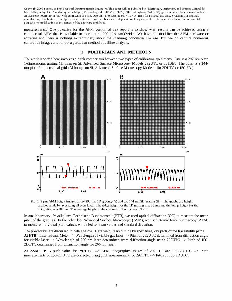
2. MATERIALS AND METHODS The work reported here involves a pitch comparison between two types of calibration specimens. One is a 292-nm pitch 1-dimensional grating (Ti lines on Si, Advanced Surface Microscopy Models 292UTC or 301BE). The other is a 144-nm pitch 2-dimensional grid (Al bumps on Si, Advanced Surface Microscopy Models 150-2DUTC or 150-2D.).
Fig. 1. 3 µm AFM height images of the 292-nm 1D grating (A) and the 144-nm 2D grating (B). The graphs are height
profiles made by averaging all scan lines. The ridge height for the 1D grating was 36 nm and the bump height for the 2D grating was 88 nm. The average height of the columns of bumps was 52 nm.
In one laboratory, Physikalisch-Technische Bundesanstalt (PTB), we used optical diffraction (OD) to measure the mean pitch of the gratings. In the other lab, Advanced Surface Microscopy (ASM), we used atomic force microscopy (AFM) to measure individual pitch values, which led to mean values and standard deviation.
The procedures are discussed in detail below. Here we give an outline by specifying key parts of the traceability paths. At PTB: International Meter --> Wavelength of visible gas laser --> Pitch of 292UTC determined from diffraction angle for visible laser --> Wavelength of 266-nm laser determined from diffraction angle using 292UTC --> Pitch of 150-2DUTC determined from diffraction angle for 266 nm laser.
At ASM: PTB pitch value for 292UTC --> AFM topographic images of 292UTC and 150-2DUTC --> Pitch measurements of 150-2DUTC are corrected using pitch measurements of 292UTC --> Pitch of 150-2DUTC.

Copyright 2008 Society of Photo-Optical Instrumentation Engineers. This paper will be published in “Metrology, Inspection, and Process Control for Microlithography XXII”, edited by John Allgair, Proceedings of SPIE Vol. 6922 (SPIE, Bellingham, WA 2008) pp. xxx-xxx and is made available as an electronic reprint (preprint) with permission of SPIE. One print or electronic copy may be made for personal use only. Systematic or multiple reproduction, distribution to multiple locations via electronic or other means, duplication of any material in this paper for a fee or for commercial purposes, or modification of the content of the paper are prohibited.
3
3. OPTICAL DIFFRACTION PROCEDURE AND RESULTS PTB has recently developed a new VIS/UV optical diffractometer2 for the traceable measurement of the grating period of one- and two-dimensional gratings. The instrument uses the Littrow diffraction arrangement for the measurement of the diffraction angles. It uses, among others, a 266 nm UV laser system which makes it possible to calibrate gratings with pitch values down to about 140 nm. With this device the mean pitch of the two-dimensional 144 nm grating has been measured with an expanded uncertainty of 0.015 nm (95% confidence level).
3.1 Set-up of the optical diffractometer
The instrument exploits a configuration which deviates slightly from an exact Littrow configuration, see Figs. 2 and 3. In the original Littrow arrangement a beam splitter is used to separate the diffracted beam. In this set-up, the back-diffracted beam runs slightly below the incident laser beam. This eliminates the need for beam splitters which cover the relatively broad range from deep UV to VIS. As a result, changing the wavelength is fast because we avoid the steps of replacing and aligning the beam splitter. Furthermore, a direct back-reflection of the diffracted beam into the laser is avoided; hence, the use of an optical isolator is not necessary. In addition, the full intensities of the incident and diffracted laser beams are used.
Fig. 2. Scheme of measurement principle. The grating is adjusted to achieve the Littrow condition, i.e. the diffracted beam is
reflected back in the direction of the incident beam (see top view). To avoid using a beam splitter to direct the diffracted beam, the incident beam is slightly inclined with respect to the grating normal (side view).
Fig. 3. Scheme of the set-up of the optical diffractometer. Three different laser systems can be applied. For the measurement of the 144 nm grating, the frequency quadrupled Nd:YAG laser with a wavelength of 266 nm has been used.

Copyright 2008 Society of Photo-Optical Instrumentation Engineers. This paper will be published in “Metrology, Inspection, and Process Control for Microlithography XXII”, edited by John Allgair, Proceedings of SPIE Vol. 6922 (SPIE, Bellingham, WA 2008) pp. xxx-xxx and is made available as an electronic reprint (preprint) with permission of SPIE. One print or electronic copy may be made for personal use only. Systematic or multiple reproduction, distribution to multiple locations via electronic or other means, duplication of any material in this paper for a fee or for commercial purposes, or modification of the content of the paper are prohibited.
4
A modified Littrow equation describes the interrelationship between the diffraction angles αm, the diffraction order m, the inclination angle β, the laser wavelength λ and the grating pitch p:
)cos()sin(2)/( βαλ ⋅=⋅ mpm (1)
The term ‘cos(β)’ in Eq.(1) considers the deviation of the measurement set-up from an ideal Littrow configuration (the well-known Littrow equation is obtained for β=0).
For the measurement described in this paper, i.e. the measurement of the 144 nm grating pitch using the 266 nm laser, only the 1st order diffraction is present and exploitable. Generally, the minimum pitch that can be measured using optical diffractometry is given by λ/2, which corresponds, however, to an impractical angle of incidence of 90°. In practice, the maximum angle of incidence is limited to about 60° to 70°, in order to restrict the width of the laser spot on the sample (an angle of 60° doubles the laser spot size on the sample). Hence, the typical minimum pitch measurable in practice is thus given by about p = λ/(2sin(70°)) which corresponds to approximately 140 nm for the 266 nm UV laser. The laser spot size on the sample is about 1 mm for vertical incidence; in the case of the Littrow diffraction angle the actually illuminated area on the sample is about 2.5 mm x 1 mm which is still smaller than the sample size of 3 mm x 4 mm.
The grating is mounted on a rotary table which is equipped with an angle measurement system. The table is rotated until the diffracted laser beam is reflected back in the direction of the incident beam. The intensity profile of the diffracted laser beam is recorded by means of a digital line array photo detector.
The traceability to SI units is assured by using a calibrated rotary encoder (Heidenhain RON 255 with 18000 line counts, angle uncertainty below 1 arcsec) and laser radiation of well-known wavelength. The vacuum wavelengths of the Ar and Ne laser transitions are tabulated with appropriate accuracy3. The wavelength in ambient air is calculated by taking the ambient temperature T, air pressure P and humidity F into account.
The actual wavelength of the 266 nm UV solid state laser was determined just before (and after) a measurement of the 144 nm grid by measuring its diffraction from a standard grating with well-known pitch. For this purpose, we used a grating (301BE from Advanced Surface Microscopy) whose pitch, 292.102±0.007 nm, was accurately calibrated using one of the gas lasers.
3.2 Measurements
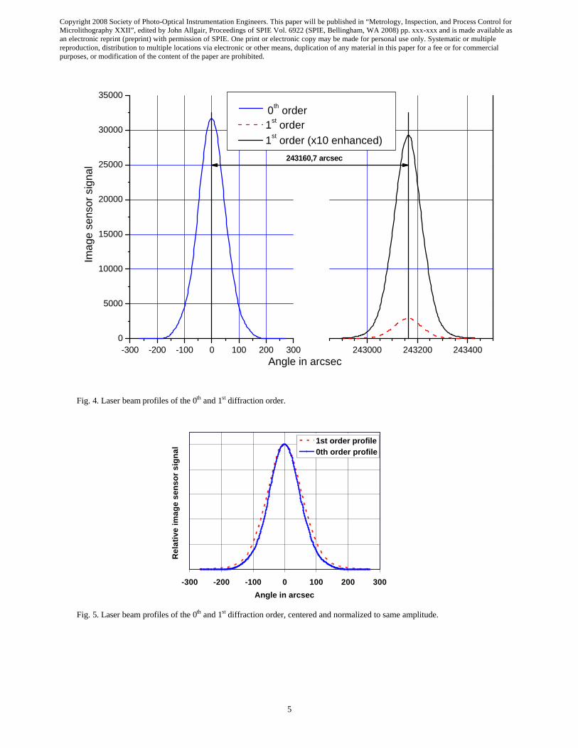
Fig. 4 shows the recorded laser beam profiles of the 1st order and the 0th order beams, respectively. The 0th order beam is the directly reflected beam for vertical incidence. As can be seen from Fig. 4, the diffraction efficiency is about 10%. The two beam profiles are shown together in Fig. 5, centered and normalized to the same amplitude. The profile of the diffracted beam is significantly broader than the 0th order profile (half width 64 arc seconds compared to 57 arc seconds). Since the bandwidth of the laser is only about 0.35 pm (1.5 GHz), we think this broadening of the beam profile is due to inhomogeneities of the pitch across the measurement spot size on the sample.
The diffraction angle of the 1st order diffraction has been determined by cross-correlating the profiles of the 0th and 1st order beams2. The peak position of the resulting correlation function can be determined with sub-arcsecond resolution, see Fig. 6.
The pitch is determined by exploiting the Littrow-Equation, Eq.1, using the diffraction angle a1, the laser wavelength ? and the inclination angle ß. Fig. 7 shows the results of 6 repeated measurements: the mean pitch in x-direction is 143.928 nm and in y-direction 143.931 nm; the repeatability is better than 0.5 pm.
Copyright 2008 Society of Photo-Optical Instrumentation Engineers. This paper will be published in “Metrology, Inspection, and Process Control for Microlithography XXII”, edited by John Allgair, Proceedings of SPIE Vol. 6922 (SPIE, Bellingham, WA 2008) pp. xxx-xxx and is made available as an electronic reprint (preprint) with permission of SPIE. One print or electronic copy may be made for personal use only. Systematic or multiple reproduction, distribution to multiple locations via electronic or other means, duplication of any material in this paper for a fee or for commercial purposes, or modification of the content of the paper are prohibited.
5
-300 -200 -100 0 100 200 3000
5000
10000
15000
20000
25000
30000
35000
243000 243200 243400
Imag
e se
nsor
sig
nal
Angle in arcsec
243160,7 arcsec
1st order 1st order (x10 enhanced)
0th order
Fig. 4. Laser beam profiles of the 0th and 1st diffraction order.
-300 -200 -100 0 100 200 300
Angle in arcsec
Rel
ativ
e im
age
sen
sor
sig
nal
1st order profile0th order profile
Fig. 5. Laser beam profiles of the 0th and 1st diffraction order, centered and normalized to same amplitude.

Copyright 2008 Society of Photo-Optical Instrumentation Engineers. This paper will be published in “Metrology, Inspection, and Process Control for Microlithography XXII”, edited by John Allgair, Proceedings of SPIE Vol. 6922 (SPIE, Bellingham, WA 2008) pp. xxx-xxx and is made available as an electronic reprint (preprint) with permission of SPIE. One print or electronic copy may be made for personal use only. Systematic or multiple reproduction, distribution to multiple locations via electronic or other means, duplication of any material in this paper for a fee or for commercial purposes, or modification of the content of the paper are prohibited.
6
43
43.1
43.2
43.3
43.4
2431
52
2431
54
2431
56
2431
58
2431
60
2431
62
2431
64
2431
66
2431
68
2431
70
Angle in arcsec
Cro
ss-c
orre
latio
n S
igna
l
Fig. 6. Cross-correlation signal between 0th and 1st diffraction order, the position of the maximum correlation signal is
denoted by the vertical line.
143.924
143.926
143.928
143.930
143.932
143.934
143.936
1 2 3 4 5 6
Measurement #
Pitc
h in
nm
y-directionx-direction
Fig. 7. Repeated measurements of the pitch in x- and y-direction; repeatability is better than 0.5 pm.
3.3 Measurement uncertainty
The measurement uncertainty budget has been estimated according to the ‘Guide to the Expression of Uncertainty in Measurement’ (GUM)4. The most important sources determining the measurement uncertainty are the uncertainty of the laser wavelength and the uncertainty of the measured diffraction angles. Table 1 summarizes the major contributors to the measurement uncertainty.
Since the actual wavelength of the UV laser is determined in the present set-up by means of a calibrated grating with known pitch (see last paragraph in section 4.1), the uncertainty of the UV laser wavelength is - at present - a major contributor to the total uncertainty. The use of a frequency stabilized UV laser would significantly reduce this uncertainty portion. In contrast, the influence of the uncertainty of the angle measurement with the rotary encoder is small. A more significant contribution to the total measurement uncertainty is due to the uncertainty of determining the centers of the diffracted beam profiles. Another uncertainty contribution originates from the small, but noticeable distortions of the laser beam profiles, caused e.g. by residual interference pattern superimposed on the Gaussian beam profiles (see example in ref. 2) or caused by sample pitch inhomogeneities.
In total, the uncertainty of the measured pitch in x- and y-direction is estimated to about 0.007 nm resulting in an expanded uncertainty (95% confidence interval) of about 0.015 nm.

Copyright 2008 Society of Photo-Optical Instrumentation Engineers. This paper will be published in “Metrology, Inspection, and Process Control for Microlithography XXII”, edited by John Allgair, Proceedings of SPIE Vol. 6922 (SPIE, Bellingham, WA 2008) pp. xxx-xxx and is made available as an electronic reprint (preprint) with permission of SPIE. One print or electronic copy may be made for personal use only. Systematic or multiple reproduction, distribution to multiple locations via electronic or other means, duplication of any material in this paper for a fee or for commercial purposes, or modification of the content of the paper are prohibited.
7
Table. 1. Uncertainty budget for the Optical Diffraction measurement of the pitch of the 144 nm grating.
Input quantity Contribution to pitch uncertainty Laser wavelength at ambient conditions 0.005 nm Possible deviation of the angles indicated by the rotary encoder (traceability of the rotary encoder)
0.0005 nm
Possible deviations due to errors in determining the centre of the beam profiles
0.002 nm
Distortion of beam profile 0.004 nm Repeatability 0.0005 nm Resulting uncertainty of pitch value 0.007 nm
4. ATOMIC FORCE MICROSCOPY PROCEDURE AND RESULTS 4.1 Data Capture
At ASM, we used a general purpose, commercial AFM. It includes a PC, NanoScope® IIIA controller and Dimension 3100 microscope (Veeco Metrology/Digital Instruments). The scanner was calibrated to factory specifications and operated open loop. The AFM can operate in TappingMode™ or contact mode and our experience indicates that the two modes give similar precision. The key results presented here were obtained using contact mode in air at ambient conditions. We captured 5x5 µm height images with 512x512 pixels at a scan rate of 5 Hz, with rounding 0.1. Rounding means that the scanner actually moves 5.5 µm on the fast axis, but captures data only for the middle 5 µm. The captured data avoids the turnaround oscillations that occur for scan rates > 3 Hz and some of the image stretching seen at the start of scan at all scan rates.
The standard used to calibrate the AFM was a specimen of Model 301BE/292UTC whose pitch was calibrated previously at PTB: (292.096 ± 0.015) nm. This was not the same specimen that was used in the optical diffraction measurements above. The test specimen was the same specimen of Model 150-2DUTC that was calibrated at PTB, with results given above.
Both specimens, i.e. the calibration standard and the test specimen, were placed in the AFM at the same time. Each was independently rotated so that the pitch features to be measured were parallel to the slow scan axis within 1°. Sample tilt relative to the XY plane of the scanner was < 0.5°. We measured pitch on the “X” axis of the 150-2DUTC specimen. For the calibration standard, 11 spots were selected within a region covering most of the area of the specimen, excluding a margin of 0.5 mm from each edge. For the test specimen, 10 spots were selected within a similar region. Each spot was previewed using the AFM’s optical microscope and if defects were found, we moved about 50 µm to a better spot. A ‘programmed move’ sequence was set up so that the AFM would automatically move to a spot, engage to the surface, capture the image, withdraw and move to the next spot. The spot sequence was arranged so that images of the test specimen were interleaved between images of the calibration standard.
4.2 Data Analysis and Results
We analyzed the height images using Advanced Surface Microscopy’s DiscTrack Plus™ software. In a given run of the software, we measured the pitch using one test specimen image and two images of the calibration standard, one captured before and one captured after the test image. This procedure (“interleaved calibration”) increases accuracy by correcting for short term drift in the AFM’s magnification and it increases precision by using redundant calibration data.
The measurements were made according to procedures described in detail elsewhere5, 6, 7 and summarized here. The software computes an average height profile Z(x) by averaging all scan lines. Peaks on the height profile correspond to ridges or columns of bumps. The centroid of each peak is its position. The difference of successive positions is an individual pitch value. Fig. 8 shows a systematic variation in pitch for different positions within an image. Using a 5th-order polynomial fit of pitch vs. position in the calibration images, the software computes a new length scale that corrects for magnification error and image distortion The corrected length scale is then applied to the basic measurement data from the test image to produce a set of corrected pitch values. For this data set, calibration reduced the standard deviation by more the 3x and removed a bias of 1 nm in the mean value (see inset table in the figure).

Copyright 2008 Society of Photo-Optical Instrumentation Engineers. This paper will be published in “Metrology, Inspection, and Process Control for Microlithography XXII”, edited by John Allgair, Proceedings of SPIE Vol. 6922 (SPIE, Bellingham, WA 2008) pp. xxx-xxx and is made available as an electronic reprint (preprint) with permission of SPIE. One print or electronic copy may be made for personal use only. Systematic or multiple reproduction, distribution to multiple locations via electronic or other means, duplication of any material in this paper for a fee or for commercial purposes, or modification of the content of the paper are prohibited.
8
288
290
292
294
296
298
300
0 1000 2000 3000 4000 5000
Position (nm)P
itch
(n
m)
Raw Pitch
Border
140
142
144
146
148
150
0 1000 2000 3000 4000 5000
Position (nm)
Pit
ch (
nm
)
Raw Pitch
Border
Calibrated
Raw CalibratedMean 144.91 143.98St.Dev. 1.30 0.40
Fig. 8. Graphs of pitch results for data set 2. Left: raw pitch as a function of position in the image for the calibration images
captured before and after a test specimen image. Right: raw and calibrated pitch for the test specimen. The dashed vertical lines indicate data exclusion borders. Because the AFM nonlinearity is hard to correct at the start of scan, we exclude pitch results from the leftmost 10% of the test image and from the leftmost 5% of the calibration images.
For each data set, we computed descriptive statistics, such as mean and standard deviation, and pooled them to obtain the overall result. The AFM mean differed from the OD mean by only 33 pm (picometer). See Fig. 9.
Data Set Count
Mean Pitch (nm)
Standard Deviation
Standard Deviation
of Mean1 30 143.85 0.42 0.082 30 143.98 0.40 0.073 30 143.83 0.55 0.104 30 143.98 0.64 0.125 31 144.05 0.69 0.126 31 143.86 0.58 0.107 31 143.89 0.50 0.098 30 143.81 0.55 0.109 31 143.92 0.55 0.10
10 30 143.77 0.59 0.11Overall AFM
Results 143.895 0.55 0.032 143.8950Overall OD results 143.928
Difference 0.033
143.7
143.8
143.9
144.0
144.1
0 2 4 6 8 10
Data Set
Mea
n P
itch
(n
m)
Fig. 9. Summary of AFM pitch results. The graph shows that there was no significant variation in mean pitch from image to
image.
4.3 Measurement uncertainty
Measured errors (type A).
Magnification error and image nonlinearity are by far the largest errors present in the original data. Analysis of Variance (ANOVA) 8 shows that we have corrected these effects as fully as is reasonably possible. Consider the following stages of correction.
1. Raw Pitch: We simply compute pitch values using our high-precision feature measurement technique.

Copyright 2008 Society of Photo-Optical Instrumentation Engineers. This paper will be published in “Metrology, Inspection, and Process Control for Microlithography XXII”, edited by John Allgair, Proceedings of SPIE Vol. 6922 (SPIE, Bellingham, WA 2008) pp. xxx-xxx and is made available as an electronic reprint (preprint) with permission of SPIE. One print or electronic copy may be made for personal use only. Systematic or multiple reproduction, distribution to multiple locations via electronic or other means, duplication of any material in this paper for a fee or for commercial purposes, or modification of the content of the paper are prohibited.
9
2. Global Calibration: We correct nonlinearity and average magnification by computing a global corrected length scale using all of the calibration images.
3. Interleaved calibration: We use the procedure described in the data analysis section. Figure 10 displays overall variation (“sum of squares”) divided into two components. “Within image” variation refers to the variance of individual pitch values within each image relative to the mean value for that image. “Between image” variation refers to the variance of mean pitch values for each image relative to the overall mean. As shown, the global calibration reduced the within image variation by a factor of 7. The between image variation was then reduced by a factor of 7 when the interleaved calibration was applied. It turns out that the between image variation was due to a systematic trend in AFM magnification, which reduced the apparent pitch values by 0.5% during the run. At stage 3, the between image sum of squares was only 2.3% of the total. This indicates that no further correction of this component is worthwhile.
0
100
200
300
400
500
600
1- Raw Pitch 2- Global Cal 3- Interleaved Cal
Su
m o
f Sq
uar
es
Within ImagesBetween Images
Fig. 10. Analysis of variance results for the entire set of data (304 pitch measurements), using different calculation
procedures. The overall pitch standard deviation is proportional to the square root of the total sum of squares.
The variation that remains after interleaved calibration appears to be random. The random effects include surface and edge roughness, local pitch variation in the test specimen (whether intrinsic or due to debris on the surface), error in the corrected length scale, tip shape changes and AFM noise. The overall standard deviation of the individual pitch values was 0.55 nm. The corresponding standard deviation of the overall mean, 0.032 nm, is reduced from the individual value by the factor vN, where N = 304.
Unmeasured errors (type B)
Some sources of error are automatically minimized by the repetitive motion that occurs when scanning an AFM image.
• The piezo creep and frame drift rate can be on the order of 30 nm/min. But we are measuring pitch on the fast scan axis. With a scan rate of 5 Hz, a single line is scanned in 0.1 sec, so its actual length would vary from its nominal length by only 30 nm/600, or 0.051 nm. With approximately 30 pitch intervals per line, creep and drift would change individual and mean pitch values by the same amount, ca. 0.0018 nm.
• Piezo hysteresis between the trace and retrace directions shifts peaks significantly, but we make all measurements using the same scan direction, so we discount this effect. Variation in hysteresis is included in the measured random variation of pitch values.
• Imperfect tracking of the surface distorts the height profile. While this affects apparent widths and angles, it should not affect pitch measurements.
Other sources of error are persistent.
• Rotation and tilt of the specimen means that the ridges or bump columns would not be exactly perpendicular to the AFM fast scan direction. We control rotation and tilt to be less than 1° and 0.5°, respectively. When the

Copyright 2008 Society of Photo-Optical Instrumentation Engineers. This paper will be published in “Metrology, Inspection, and Process Control for Microlithography XXII”, edited by John Allgair, Proceedings of SPIE Vol. 6922 (SPIE, Bellingham, WA 2008) pp. xxx-xxx and is made available as an electronic reprint (preprint) with permission of SPIE. One print or electronic copy may be made for personal use only. Systematic or multiple reproduction, distribution to multiple locations via electronic or other means, duplication of any material in this paper for a fee or for commercial purposes, or modification of the content of the paper are prohibited.
10
values are different for the calibration and test specimens, they affect pitch by a cosine factor, amounting to 0.015% and 0.004%, respectively. To the extent that these factors exist for the calibration standard, they would decrease the reported pitch of the test specimen. To the extent they exist for the test specimen, they would increase its reported pitch. An error of 0.015% is 0.022 nm at 144 nm. This effect gives a constant bias within a given run and contributes to a run to run reproducibility error when specimens are replaced.
• The stated uncertainty of the 292UTC mean pitch is 0.0075 nm.
• Temperature dependence is discounted because the calibration standard and the test specimen both use silicon substrates and because both are measured under the same environmental conditions.
The uncertainty budget is shown in table 2. The outcome for the AFM method is that the expanded uncertainty for single pitch values is ± 1.1 nm and for mean pitch it is ± 0.08 nm. It is clear that the uncertainty of single pitch values virtually equals the measured standard deviation and that the uncertainty of the mean value is dominated by the measured standard deviation of the mean. The next most important factor is the cosine error due to sample rotation. This is an important result because it indicates a path to even higher accuracy: capture more pitch measurements and control the sample rotation better.
Table. 2. Uncertainty budget for the Atomic Force Microscope measurement of the pitch of the 144 nm grating.
Input Quantity Factor, if proportional to pitch
Contribution to Pitch Uncertainty for single pitch values (nm)
Contribution to Pitch Uncertainty for mean pitch(nm)
Random error in measured data 0.55 0.032
Pitch uncertainty of 292 nm standard (expanded uncertainty = 0.015 nm) 0.0026% 0.0037 0.0037
Sample rotation difference (cos(1 degree)) 0.015% 0.022 0.022
Sample tilt difference (cos(0.5 degree)) 0.0040% 0.0058 0.0058 Piezo creep and frame drift 0.0018 0.0018
Resulting uncertainty of pitch value 0.55 0.039 Expanded uncertainty, with coverage factor k = 2. 1.1 0.079
As a check of the uncertainty budget, we consider a set of similar runs in which we measured five different Model 150-2DUTC specimens against either of the two PTB-certified specimens (292 and 144 nm pitch) used here. In a total of 9 measurements of X and Y axis pitch, we found an overall mean of 143.906 nm, with standard deviation of mean = 0.034 nm. This standard deviation would include all of the effects listed above plus possible differences in pitch between the X and Y axes and between different specimens. The fact that the observed standard deviation is about the same as the 0.039 nm uncertainty given above is good support for our uncertainty model.
5. DISCUSSION AND CONCLUSIONS The AFM and OD measurements of mean pitch differed by only 33 pm, which is less than the 95% confidence interval (80 pm) for the comparison. This provides additional confidence in the AFM results.
The uncertainty of the AFM measurement was about 5x larger than the OD uncertainty. One way to understand this is to consider the number of pitch intervals sampled by both methods. The AFM measurements related to 304 pitch values. The OD measurements involved a spot about 2.5 mm wide, spanning about 17300 pitch intervals. The square root of the ratio 17300/304 is 7.5, which is not much different from the observed uncertainty ratio.
Copyright 2008 Society of Photo-Optical Instrumentation Engineers. This paper will be published in “Metrology, Inspection, and Process Control for Microlithography XXII”, edited by John Allgair, Proceedings of SPIE Vol. 6922 (SPIE, Bellingham, WA 2008) pp. xxx-xxx and is made available as an electronic reprint (preprint) with permission of SPIE. One print or electronic copy may be made for personal use only. Systematic or multiple reproduction, distribution to multiple locations via electronic or other means, duplication of any material in this paper for a fee or for commercial purposes, or modification of the content of the paper are prohibited.
11
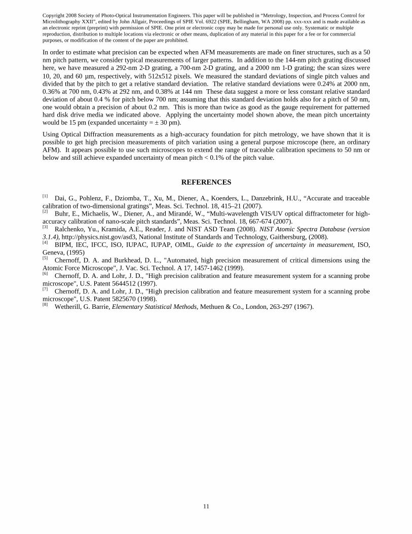
In order to estimate what precision can be expected when AFM measurements are made on finer structures, such as a 50 nm pitch pattern, we consider typical measurements of larger patterns. In addition to the 144-nm pitch grating discussed here, we have measured a 292-nm 2-D grating, a 700-nm 2-D grating, and a 2000 nm 1-D grating; the scan sizes were 10, 20, and 60 µm, respectively, with 512x512 pixels. We measured the standard deviations of single pitch values and divided that by the pitch to get a relative standard deviation. The relative standard deviations were 0.24% at 2000 nm, 0.36% at 700 nm, 0.43% at 292 nm, and 0.38% at 144 nm These data suggest a more or less constant relative standard deviation of about 0.4 % for pitch below 700 nm; assuming that this standard deviation holds also for a pitch of 50 nm, one would obtain a precision of about 0.2 nm. This is more than twice as good as the gauge requirement for patterned hard disk drive media we indicated above. Applying the uncertainty model shown above, the mean pitch uncertainty would be 15 pm (expanded uncertainty = ± 30 pm).
Using Optical Diffraction measurements as a high-accuracy foundation for pitch metrology, we have shown that it is possible to get high precision measurements of pitch variation using a general purpose microscope (here, an ordinary AFM). It appears possible to use such microscopes to extend the range of traceable calibration specimens to 50 nm or below and still achieve expanded uncertainty of mean pitch < 0.1% of the pitch value.
REFERENCES
[1] Dai, G., Pohlenz, F., Dziomba, T., Xu, M., Diener, A., Koenders, L., Danzebrink, H.U., “Accurate and traceable calibration of two-dimensional gratings”, Meas. Sci. Technol. 18, 415–21 (2007). [2] Buhr, E., Michaelis, W., Diener, A., and Mirandé, W., “Multi-wavelength VIS/UV optical diffractometer for high-accuracy calibration of nano-scale pitch standards”, Meas. Sci. Technol. 18, 667-674 (2007). [3] Ralchenko, Yu., Kramida, A.E., Reader, J. and NIST ASD Team (2008). NIST Atomic Spectra Database (version 3.1.4), http://physics.nist.gov/asd3, National Institute of Standards and Technology, Gaithersburg, (2008). [4] BIPM, IEC, IFCC, ISO, IUPAC, IUPAP, OIML, Guide to the expression of uncertainty in measurement, ISO, Geneva, (1995) [5] Chernoff, D. A. and Burkhead, D. L., "Automated, high precision measurement of critical dimensions using the Atomic Force Microscope", J. Vac. Sci. Technol. A 17, 1457-1462 (1999). [6] Chernoff, D. A. and Lohr, J. D., "High precision calibration and feature measurement system for a scanning probe microscope", U.S. Patent 5644512 (1997). [7] Chernoff, D. A. and Lohr, J. D., "High precision calibration and feature measurement system for a scanning probe microscope", U.S. Patent 5825670 (1998). [8] Wetherill, G. Barrie, Elementary Statistical Methods, Methuen & Co., London, 263-297 (1967).