picmg 34 draft 1.0 - pudn.comread.pudn.com/downloads132/ebook/562747/picmg3_4d1_0.pdfpicmg 3.4 draft...
TRANSCRIPT

DO NOT SPECIFY OR CLAIM CONFORMANCE TO THIS DRAFT SPECIFICATION
AdvancedTCATM
PICMG 3.4 ® Revision D1.0 Specification
PCI Express and Advanced Switching for AdvancedTCATM
Systems
May 12, 2003

PICMG 3.4 Draft Rev. 1.0 ii DO NOT SPECIFY OR CLAIM CONFORMANCE TO THIS DRAFT SPECIFICATION
Copyright 2003, PCI Industrial Computer Manufacturers Group. The attention of adopters is directed to the possibility that compliance with or adoption of PICMG specifications may require use of an invention covered by patent rights. PICMG shall not be responsible for identifying patents for which a license may be required by any PICMG specification or for conducting legal inquiries into the legal validity or scope of those patents that are brought to its attention. PICMG specifications are prospective and advisory only. Prospective users are responsible for protecting themselves against liability for infringement of patents. NOTICE: The information contained in this document is subject to change without notice. The material in this document details a PICMG specification in accordance with the license and notices set forth on this page. This document does not represent a commitment to implement any portion of this specification in any company's products. WHILE THE INFORMATION IN THIS PUBLICATION IS BELIEVED TO BE ACCURATE, PICMG MAKES NO WARRANTY OF ANY KIND, EXPRESS OR IMPLIED, WITH REGARD TO THIS MATERIAL INCLUDING, BUT NOT LIMITED TO ANY WARRANTY OF TITLE OR OWNERSHIP, IMPLIED WARRANTY OF MERCHANTABILITY OR WARRANTY OF FITNESS FOR PARTICULAR PURPOSE OR USE. In no event shall PICMG be liable for errors contained herein or for indirect, incidental, special, consequential, reliance or cover damages, including loss of profits, revenue, data or use, incurred by any user or any third party. Compliance with this specification does not absolve manufacturers of AdvancedTCATM equipment from the requirements of safety and regulatory agencies (UL, CSA, FCC, IEC, etc.). PICMG, CompactPCI, and the PICMG and CompactPCI logos are registered trademarks, and AdvancedTCA and ATCA are trademarks, of the PCI Industrial Computer Manufacturers Group. All other brand or product names may be trademarks or registered trademarks of their respective holders.

PICMG 3.4 Draft Rev. 1.0 iii DO NOT SPECIFY OR CLAIM CONFORMANCE TO THIS DRAFT SPECIFICATION
TABLE OF CONTENTS
REVISION HISTORY......................................................................................................................V
1 INTRODUCTION AND OBJECTIVES ..................................................................................1
1.1 SCOPE..................................................................................................................................1 1.2 OBJECTIVES ......................................................................................................................1 1.3 REFERENCE DOCUMENTS .............................................................................................2
1.3.1 Reference Specifications....................................................................................................................................2 1.3.2 Environment and Regulatory Documents.........................................................................................................2
1.4 CONTRIBUTORS ...............................................................................................................3 1.5 SPECIAL WORD USAGE ..................................................................................................3 1.6 NAME AND LOGO USAGE ..............................................................................................4
1.6.1 Logo Use.............................................................................................................................................................4 1.6.2 Trademark Policy...............................................................................................................................................4
1.7 SIGNAL NAMING CONVENTIONS ................................................................................5 1.8 INTELLECTUAL PROPERTY...........................................................................................5 1.9 ACRONYMS AND DEFINITIONS....................................................................................5
2 PICMG 3.0 COMPLIANCE .....................................................................................................6
3 FABRIC INTERFACE ..............................................................................................................7
3.1 OVERVIEW.........................................................................................................................7 3.2 PICMG 3.0 PORT MAPPING .............................................................................................7 3.3 PCI EXPRESS LANES........................................................................................................7 3.4 PIN ASSIGNMENTS...........................................................................................................8 3.5 PCI EXPRESS LINK WIDTH NEGOTIATION ................................................................9 3.6 SIGNAL INTEGRITY.........................................................................................................9
3.6.1 PICMG 3.0 Signal Integrity Requirements ......................................................................................................9
4 SYSTEM MANAGEMENT ....................................................................................................10
4.1 OVERVIEW.......................................................................................................................10 4.2 PICMG 3.0 SHELF MANAGEMENT REQUIREMENTS ..............................................10 4.3 PICMG 3.4 IMPLEMENTATION REQUIREMENTS.....................................................11 4.4 IPM CONTROLLER REQUIREMENTS..........................................................................11 4.5 ELECTRONIC KEYING REQUIREMENTS ...................................................................12
4.5.1 Link Designator............................................................................................................................................... 12 4.5.2 Link Type......................................................................................................................................................... 13 4.5.3 Link Type Extension....................................................................................................................................... 13 4.5.4 Link Grouping ID............................................................................................................................................ 13
4.6 EXAMPLE INTERFACE INFORMATION .....................................................................14 4.7 E-KEYING AND LINK WIDTH NEGOTIATION..........................................................14 4.8 SHELF MANAGER...........................................................................................................15 4.9 BASE INTERFACE REQUIREMENTS ...........................................................................15

PICMG 3.4 Draft Rev. 1.0 iv DO NOT SPECIFY OR CLAIM CONFORMANCE TO THIS DRAFT SPECIFICATION
LIST OF FIGURES
Figure 1: AdvancedTCA Fabric Interface Generic Pin Mappings .......................................................7 Figure 2: PICMG 3.0 System Management Model............................................................................11
LIST OF TABLES
Table 1: PICMG 3.4 Channel Options .................................................................................................8 Table 2: Pin Mappings for PICMG 3.4 Channel Interface Options .....................................................8 Table 3: Link Designator Fields (12 bits total) ..................................................................................12 Table 4: Link Type Values (8 bits) ....................................................................................................13 Table 5: Link Type Extension (4 bits)................................................................................................13 Table 6: Example 1 Port FRU Information........................................................................................14 Table 7: Example 2 x4 PCI Express Implementation ........................................................................15

PICMG 3.4 Draft Rev. 1.0 v DO NOT SPECIFY OR CLAIM CONFORMANCE TO THIS DRAFT SPECIFICATION
REVISION HISTORY
Revision Date Description
Draft 0.40 October 11, 2002 • Original Draft
Draft 0.60 December 18, 2002 • First complete draft based on subcommittee discussions
Draft 0.70 January 29, 2003 • Updated draft based on subcommittee feedback
Draft 0.71 February 3, 2003 • Updated draft based on 1/29 subcommittee meeting
Draft 0.72 March 12, 2003 • Updated draft based on 2/26 subcommittee meeting.
• Removed all definitions and acronyms that are either not used in the document or are included in PICMG 3.0 to ensure there are no conflicting definitions.
Draft 0.8 March 19, 2003 • Updated front matter to comply with the PICMG 3.0 specification.
• Updated draft based on 3/12 subcommittee meeting.
Draft 0.9 April 7, 2003 • No changes from 0.8 except numbering of document.
Draft 1.0 May 12, 2003 • Updated based on Final Subcommittee Ballot for PICMG 3.4 D0.9 feedback.

PICMG 3.4 Draft Rev. 1.0 1 DO NOT SPECIFY OR CLAIM CONFORMANCE TO THIS DRAFT SPECIFICATION
1 INTRODUCTION AND OBJECTIVES
The PICMG 3.4 specification is a member of the PICMG 3.0 AdvancedTCATM series of specifications. The PICMG 3.0 base specification defines a Board and Shelf architecture sharing a common Backplane. PICMG 3.4 Boards are intended for use with PICMG 3.0 backplanes, sub-racks and shelves. The specification is sufficiently generic that it can accommodate many different point-to-point differential pair serial link standards. PICMG 3.4 defines the use of both PCI Express Base and Advanced Switching based on PCI Express within an AdvancedTCA platform. The PCI Express Base specification was ratified by the PCI Special Interest Group in July 2002. The Advanced Switching specification, which defines functional extensions to the PCI Express Base PHY and link layers, is currently under development. Because PCI Express and Advanced Switching are electrically compatible, PICMG 3.4 requirements apply to both technologies. The Advanced Switching Specification is targeted at enabling additional communications capabilities, including a globally flat addressable fabric used to enable star and mesh topologies, message passing, multicast and broadcast capabilities, as well as congestion management and transport reliability.
1.1 Scope The scope of the PICMG 3.4 subcommittee effort includes design rules and guidelines for the implementation of PCI Express and/or Advanced Switching based Node, Mesh-Enabled and Hub Boards based on the PICMG 3.0 base specification.
1.2 Objectives The content of this document is derived from, and is dependent upon the PICMG 3.0 base specification. It is not intended as a standalone document or to be used separately from the base specification. PICMG 3.4 builds upon the PICMG 3.0 specification to meet the following objectives:
• Define the PCI Express signals to be used over the Fabric Interface defined in the PICMG 3.0 base specification.
• Provide guidelines for the use of x1, x2, and x4 PCI Express links through Link Width Negotiation.
• Support over each PICMG 3.0 Channel for up to 10Gbps PCI Express links. • Establish the System Management criteria for ensuring compatibility between PICMG
3.4 boards. • Define design rules such that devices compatible with other PICMG 3.0 standards can be
safely inserted in the same system, even if they do not interoperate. • Provide example topologies and example implementations for Board and Backplane
developers.

PICMG 3.4 Draft Rev. 1.0 2 DO NOT SPECIFY OR CLAIM CONFORMANCE TO THIS DRAFT SPECIFICATION
1.3 Reference Documents The following sections list the publications that are relevant to this specification. Many of the specifications are subject to periodic and independent updates and are the responsibility of their respective organizations. Version and/or revision numbers of each specification should be carefully checked if used in conjunction with this specification. 1.3.1 Reference Specifications All documents may be obtained from their respective organizations.
• PCI Local Bus Specification, Revision 2.2 and 2.31 PCI Special Interest Group, 5440 SW Westgate Drive #217, Portland, OR 97221, Tel: (503) 291-2569, Fax: (503) 297-1090 www.pcisig.com
• PCI Express Base Specification, Revision 1.0, PCI Special Interest Group, 5440 SW Westgate Drive #217, Portland, OR 97221, Tel: (503) 291-2569, Fax: (503) 297-1090 www.pcisig.com
• PICMG® Policies and Procedures for Specification Development, Revision 1.5, October 5, 2001, PCI Industrial Computer Manufacturers Group (PICMG®), 401 Edgewater Place, Suite 500, Wakefield, MA 01880 USA, Tel: 781.224.1100, Fax: 781.224.1239, www.picmg.org
• PICMG® 3.0 Revision 1.0, AdvancedTCATM Base Specification, PCI Industrial Computer Manufacturers Group (PICMG®), 401 Edgewater Place, Suite 500, Wakefield, MA 01880 USA, Tel: 781.224.1100, Fax: 781.224.1239, www.picmg.org
• ANSI/TIA/EIA-644-A-2001: Electrical Characteristics of Low Voltage Differential Signaling (LVDS) Interface Circuits, January 1, 2001
1.3.2 Environment and Regulatory Documents All environment and regulatory requirements that pertain to the PICMG 3.4 specification are cited within the PICMG 3.0 base specification.
1 Reference to PCI Local Bus Specification R2.3 is solely to provide a base for VPD keyword definitions with no
intent to require 2.3 compliance in other respects.

PICMG 3.4 Draft Rev. 1.0 3 DO NOT SPECIFY OR CLAIM CONFORMANCE TO THIS DRAFT SPECIFICATION
1.4 Contributors
The following companies participated in the PICMG® 3.4 Final Subcommittee ballot:
Advanet Pentair
Brooktrout Pigeon Point Systems
Bustronic PLX Technology, Inc
Diversified Technology Rittal/Kaparel
Don Harrison Sanmina-SCI
General Micro Systems SBS Technologies
GNP SRC
Hybricon StarGen
Intel Corp. Tekelec
Interphase TranSwitch
1.5 Special Word Usage In this specification the following key words (in bold text) will be used:
may: indicates flexibility of choice with no implied preference.
should: indicates flexibility of choice with a strongly preferred implementation.
shall: indicates a mandatory requirement. Designers shall implement such mandatory requirements to ensure interchangeability and to claim conformance with this specification.
Note: When not in bold text, the words “may”, “should”, and “shall” are being used in the traditional sense; that is, they do not adhere to the strict meanings described above.
PICMG 3.4 Draft Rev. 1.0 4 DO NOT SPECIFY OR CLAIM CONFORMANCE TO THIS DRAFT SPECIFICATION
1.6 Name And Logo Usage The PCI Industrial Computer Manufacturers Group's policy regarding the use of its logos and trademarks is as follows: 1.6.1 Logo Use • Permission to use the PICMG® organization logo is automatically granted to designated
members only, as stipulated on the most recent Membership Privileges document (available on the Web at www.picmg.org), during the period of time for which their membership dues are paid. Non-members of PICMG® may not use the PICMG® organization logo.
• The PICMG® organization logo must be printed in black or in color as shown in the files
available for download from the members’ side of the Web site. The center bar of the logo containing the phrase “PICMG” is set horizontally, and the aspect ratio of the entire logo must be maintained, but the size may be varied. Nothing may be added to or deleted from the PICMG® logo.
• Manufacturers’ distributors and sales representatives mat use the AdvancedTCATM logos (but
not the PICMG® organization logo) in promoting products sold under the name of the manufacturer.
• The use of the AdvancedTCATM logos is a privilege granted by the PICMG® organization to
companies who have purchased the relevant AdvancedTCATM specifications (or acquired them as a member benefit) and who believe their products comply with these specifications. Use of the AdvancedTCATM logo by either members or non-members implies such compliance. Misuse of the AdvancedTCATM logos may result in PICMG®‘s revoking permission to use them.
• The AdvancedTCATM logos must be used exactly as shown in the files available for
download from the PICMG® Web site. The aspect ratios of the logos must be maintained, but the sizes may be varied. Nothing may be added to or deleted from the AdvancedTCATM logos.
• Color information for the red parts of the AdvancedTCATM logos is as follows:
• Pantone 032 CVC is the closest match. • CMYK colors are C:0, M:100, Y:100, K:0. • RGB colors are R:237, G:28, B:36.
1.6.2 Trademark Policy • The PICMG® name and logo are registered trademarks of PICMG®. Registered trademarks
must be followed by the symbol, and the following statement must appear in all published literature and advertising material in which the logo appears:

PICMG 3.4 Draft Rev. 1.0 5 DO NOT SPECIFY OR CLAIM CONFORMANCE TO THIS DRAFT SPECIFICATION
PICMG and the PICMG logo are registered trademarks of the PCI Industrial Computer Manufacturing Group.
• The AdvancedTCATM name and logos and the ATCATM name and logo are trademarks of PICMG® in process of registration. These trademarks must be followed by the symbol, and the following statement must appear in all published literature and advertising material in which the logo appears: AdvancedTCA, ATCA, and the AdvancedTCA and ATCA logos are trademarks of the PCI Industrial Computer Manufacturing Group.
1.7 Signal Naming Conventions All signals are active high unless denoted by a trailing # symbol. Differential signals are denoted by a trailing + (positive) or – (negative) symbol.
1.8 Intellectual Property The PICMG 3.4 AdvancedTCA Specification conforms to the Intellectual Property guidelines outlined in the PICMG Policies and Procedures for Specification Development.
1.9 Acronyms and Definitions Acronyms and definitions used throughout this document are defined in the PICMG 3.0 base specification, Section 1.8. In order to maintain consistency they are not repeated here. The following term is used in this document but is not part of the PICMG 3.0 definitions. PCI Express Lane A set of differential signal pairs, one pair for transmission and
one pair for reception. A by-N Link is composed of N Lanes. PCI Express Link The collection of two PCI Express Ports and their
interconnecting Lanes. A PCI Express Link is a dual-simplex communication path.
Link Width Negotiation
The process where two PCI Express Ports negotiate a common number of PCI Express Lanes that will be used to interconnect the two PCI Express Ports and form a single PCI Express Link.

PICMG 3.4 Draft Rev. 1.0 6 DO NOT SPECIFY OR CLAIM CONFORMANCE TO THIS DRAFT SPECIFICATION
2 PICMG 3.0 COMPLIANCE
The PICMG 3.4 specification is wholly derived from the PICMG 3.0 specification, which fully addresses all issues with regard to mechanical form, power distribution, and thermal characteristics. The notes provided in this section are provided for continuity; no exceptions to the base specification have been taken. A PICMG 3.4 device shall conform to all the mechanical, power, and thermal specifications set forth in the PICMG 3.0 specification.

PICMG 3.4 Draft Rev. 1.0 7 DO NOT SPECIFY OR CLAIM CONFORMANCE TO THIS DRAFT SPECIFICATION
3 FABRIC INTERFACE
3.1 Overview This section defines the mapping of PCI Express signals to the Fabric Interface of the PICMG 3.0 specification in order to ensure compatibility with standard PICMG 3.0 Backplanes. In addition, the specification will enable interoperability between PICMG 3.4 compliant systems. 3.2 PICMG 3.0 Port Mapping Each AdvancedTCA Fabric Interface provides eight differential signal pairs that are used for Board-to-Board communication. Up to 16 Fabric Interfaces are provided, which are distributed according to the requirements detailed in Section 6 of the PICMG 3.0 specification. Each Fabric Interface uses two rows of connections in Zone 2. The pin mappings are shown in Figure 1.
Figure 1: AdvancedTCA Fabric Interface Generic Pin Mappings
3.3 PCI Express Lanes PCI Express supports multiple Lanes and can be configured in a variety of widths including x1, x2, x4, x8, x12, x16, and x32. A Lane is defined as a set of differential signal pairs (one pair for transmit and one for receive), which is synonymous with the Port definition in PICMG 3.0. The Channel types supported in PICMG 3.4 consist of x1, x2, and x4 configurations through the PICMG 3.0 Backplane. Other Port configurations are not supported by the PICMG 3.4 specification. Pin assignments are shown in the following section. These Channel options are shown in Table 1 with their associated bit rates in each direction of the full duplex Port. In the multiple Lane cases, the Lanes are aggregated to form a single logical Channel. NOTE: “Lane” is a PCI Express term, “Port” is an AdvancedTCA term. With respect to the PICMG 3.4 specification, these terms are equivalent.
A B C D E F G H n Tx2+ Tx2- Rx2+ Rx2- Tx3+ Tx3 - Rx3+ Rx3-
n + 1 Tx0+ Tx0- Rx0+ Rx0- Tx1+ Tx1 - Rx1+ Rx1-
Port 0 Port 1
Port 2 Port 3

PICMG 3.4 Draft Rev. 1.0 8 DO NOT SPECIFY OR CLAIM CONFORMANCE TO THIS DRAFT SPECIFICATION
Table 1: PICMG 3.4 Channel Options
Option Interface Lanes/Ports Maximum bit rate 1 PCI Express 1 2.5Gb/s 2 PCI Express 2 5.0Gb/s 3 PCI Express 4 10.0Gb/s
3.4 Pin Assignments The PICMG 3.4 specification supports the Dual Star, Dual-Dual Star, and Mesh topologies specified in Section 6 of the base specification, where the Channel mappings for these topologies can be referenced. PICMG 3.4 Boards shall support single (x1), dual (x2), or quad (x4) Port Channel configurations defined in the PCI Express Base Specification. Other Port configurations are not compliant configurations. Table 2 shows the pin assignments for each Channel configuration for one Fabric Channel. When a PICMG 3.4 Board populates row N of a Backplane interface connector and that Board does not support the Port to which the pins connect, a 100 Ohm +/- 10% resistive termination shall be present across the Rx signal pair on the Board.
Table 2: Pin Mappings for PICMG 3.4 Channel Interface Options
AdvancedTCA Pins
1 Port Channel
2 Port Channel
4 Port Channel
Tx0+ Port0 Tx+ Port0 Tx+ Port0 Tx+ Tx0- Port0 Tx- Port0 Tx- Port0 Tx- Rx0+ Port0 Rx+ Port0 Rx+ Port0 Rx+ Rx0- Port0 Rx- Port0 Rx- Port0 Rx- Tx1+ NC Port1 Tx+ Port1 Tx+ Tx1- NC Port1 Tx- Port1 Tx- Rx1+ Term Port1 Rx+ Port1 Rx+ Rx1- Term Port1 Rx- Port1 Rx- Tx2+ NC NC Port2 Tx+ Tx2- NC NC Port2 Tx- Rx2+ Term Term Port2 Rx+ Rx2- Term Term Port2 Rx- Tx3+ NC NC Port3 Tx+ Tx3- NC NC Port3 Tx- Rx3+ Term Term Port3 Rx+ Rx3- Term Term Port3 Rx-

PICMG 3.4 Draft Rev. 1.0 9 DO NOT SPECIFY OR CLAIM CONFORMANCE TO THIS DRAFT SPECIFICATION
3.5 PCI Express Link Width Negotiation PICMG 3.4 Boards shall support Link Width Negotiation, as defined in the PCI Express Base Specification v1.0, to determine the number of Ports connected in a Fabric Channel. 3.6 Signal Integrity Signal integrity requirements are imposed on all PICMG 3.4 Node, Mesh-Enabled and Hub Boards from two sources: PICMG 3.0 requirements; and PCI Express requirements. PICMG 3.0 defines the allowable worst-case limits on Backplane signal integrity and also imposes design constraints on Boards. The PCI Express specification also defines an overall link budget requirement at the receiver. The Node, Mesh-Enabled and Hub Board signal performance requirements are derived from these two constraints. 3.6.1 PICMG 3.0 Signal Integrity Requirements PICMG 3.0 specifies design requirements and guidelines for both Boards and Backplanes to guarantee signal integrity and interoperability. PICMG 3.0 Backplanes are guaranteed not to exceed defined signal integrity limits and Node Board requirements are derived from this Backplane performance.
• PICMG 3.4 Boards should comply with PICMG 3.0 Board layout requirements. PICMG 3.4 Boards that do not comply with the PICMG 3.0 requirements shall validate performance using signal integrity simulations that meet the PCI Express specifications.
• PICMG 3.4 Boards shall comply with the design requirements set forth in section 8.3 of the PICMG 3.0 specification.
• Fabric Interface device transmitters and receivers shall meet the specifications as defined in section 4.3 (Electrical Sub-lock) of the PCI Express specification.
• A PICMG 3.4 receiver shall be AC coupled at or on the receiver chip. The AC coupling capacitors at the receiver shall be 100 nF +/- 1%.
• Boards that do not implement all four Ports in a Channel shall terminate the Rx pairs of the unused Ports. The Rx signals shall be terminated with a 100 Ohm +/- 10% resistive termination across the pairs (e.g. Rx3+, Rx3-) when the connector for the pairs is present.
• The PICMG 3.4 receivers shall withstand a minimum of 1600 mV peak-to-peak differential voltage without any adverse impact to long-term reliability, whether or not the receiver hardware is powered.

PICMG 3.4 Draft Rev. 1.0 10 DO NOT SPECIFY OR CLAIM CONFORMANCE TO THIS DRAFT SPECIFICATION
4 SYSTEM MANAGEMENT
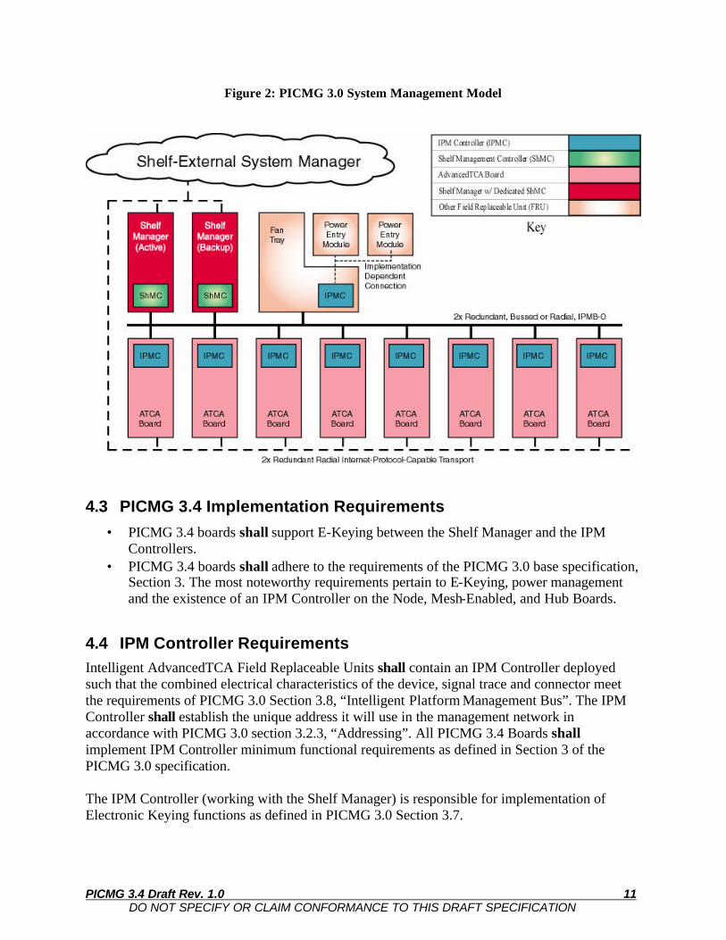
4.1 Overview The PICMG 3.4 system manageability requirements are derived from and based upon the features provisioned in Section 3, Shelf Management, of the PICMG 3.0 base specification. System Management is applicable to PCI Express over the Fabric interfaces. Two situations where systems manageability is most evident in its interaction with the PCI Express signaling are during system power-up and insertion/extraction of a Board. The control interface between System Management and the PCI Express implementation is based on Intelligent Platform Management Interface (IPMI) messaging. IPMI messaging is used to facilitate both Electronic-Keying (E-Keying) and power state protocol processes. Ultimately, the actions taken by the Node, Mesh-Enabled, and Hub Boards, in order to comply with the E-keying and power management messages are implementation dependent. 4.2 PICMG 3.0 Shelf Management Requirements PICMG 3.0 defines a distributed management model with three levels of functionality. The intelligent devices in each level are designed to have access to all Board and Shelf operations for monitoring system health. The System Management application(s) is designed to collect this information, report anomalies, and take corrective action when needed. The key components shown in Figure 2 are:
1. The Intelligent Platform Management Controller (IPMC) is the device that implements management functions on every Node, Mesh-Enabled, and Hub Board. It has control of the Payload power interface, Fabric Interface, and monitoring sensors.
2. The Shelf Manager is a Shelf-level entity that monitors Shelf components and also communicates to both the System Manager and all IPM Controllers.
3. The System Manager is a higher-level entity, which most likely is a software application residing on a remote workstation or server. Implementation details are beyond the scope of the PICMG 3.0 specifications.
4. A redundant Intelligent Platform Management Bus (IPMB), which is implemented on the Backplane for low-speed communication between the Shelf Manager and the IPM Controllers.
5. An IP-based network interface is implemented on the Shelf Manager for communication to the System Management applications.
The dual IPMB is referred to as IPMB-0 and uses I2C as its physical layer and the IPMI as its messaging protocol. IPMI (as extended by PICMG 3.0) also defines methods for Hot Swap event handling, sampling sensor data and maintaining data records for hardware events and therefore makes up a significant part of the IPMC and Shelf Manager implementation. These functions are typically implemented as firmware on embedded processors with the necessary I2C or network interface hardware.
PICMG 3.4 Draft Rev. 1.0 11 DO NOT SPECIFY OR CLAIM CONFORMANCE TO THIS DRAFT SPECIFICATION
Figure 2: PICMG 3.0 System Management Model
4.3 PICMG 3.4 Implementation Requirements
• PICMG 3.4 boards shall support E-Keying between the Shelf Manager and the IPM Controllers.
• PICMG 3.4 boards shall adhere to the requirements of the PICMG 3.0 base specification, Section 3. The most noteworthy requirements pertain to E-Keying, power management and the existence of an IPM Controller on the Node, Mesh-Enabled, and Hub Boards.
4.4 IPM Controller Requirements Intelligent AdvancedTCA Field Replaceable Units shall contain an IPM Controller deployed such that the combined electrical characteristics of the device, signal trace and connector meet the requirements of PICMG 3.0 Section 3.8, “Intelligent Platform Management Bus”. The IPM Controller shall establish the unique address it will use in the management network in accordance with PICMG 3.0 section 3.2.3, “Addressing”. All PICMG 3.4 Boards shall implement IPM Controller minimum functional requirements as defined in Section 3 of the PICMG 3.0 specification. The IPM Controller (working with the Shelf Manager) is responsible for implementation of Electronic Keying functions as defined in PICMG 3.0 Section 3.7.

PICMG 3.4 Draft Rev. 1.0 12 DO NOT SPECIFY OR CLAIM CONFORMANCE TO THIS DRAFT SPECIFICATION
4.5 Electronic Keying Requirements The Electronic Keying mechanism defined in Section 3.7 of the base specification verifies the fabric compatibility between Boards, thereby preventing possible damage or mis-operation between Boards having two different types of Links. All PICMG 3.4 Boards shall implement Electronic Keying as defined in Section 3.7 of the PICMG 3.0 specification. Upon detection of an ATCA Board during the power-on state or Board insertion, the Shelf Manager accesses the Board’s FRU Information, seeking Board Point-to-Point Connectivity Record(s) that describe the Board’s connections to the Fabric Interface. One or more of these records shall be present on any PICMG 3.4 Board. These records contain Link Descriptors describing potential Links that can be established between that Board and the Backplane in terms of Link Descriptor fields: Link Designator, Link Type, Link Type Extension, and Link Grouping ID. Via the Backplane Point-to-Point Connectivity Record in the Shelf FRU Information, the Shelf Manager can determine the other Boards in the Shelf that connect to Channels on the PICMG 3.4 Board that is being integrated into the Shelf. The Shelf Manager determines if they are compatible. The Shelf Manager’s determination of compatible Ports is based on a binary comparison of each of the Link Descriptor fields (factoring any application dependent policies that may be implemented in the Shelf Manager). Upon identifying a match, an IPMI message goes to both IPM Controllers, stating that the Link should be enabled or disabled, augmented with a description of the Channel capabilities required. This notification occurs via the “Set Port State (Enable)” or “Set Port State (Disable)” commands. The following subsections provide the requirements governing Link Descriptor fields for PICMG 3.4 Boards. 4.5.1 Link Designator For all PICMG 3.4 Boards, Link Descriptors shall identify the Link Interface (Base, Fabric, or Update Channel), the Channel Number, and which Ports are enabled. Table 3 shows the Link Designators fields.
Table 3: Link Designator Fields (12 bits total)
Description Bits Channel Number 6 bits
Interface 00b = Base Interface
01b = Fabric Interface 10b = Update Port Interface
11b = Reserved
2 bits
Port 0-3 Flags 4 bits
PICMG 3.4 Draft Rev. 1.0 13 DO NOT SPECIFY OR CLAIM CONFORMANCE TO THIS DRAFT SPECIFICATION
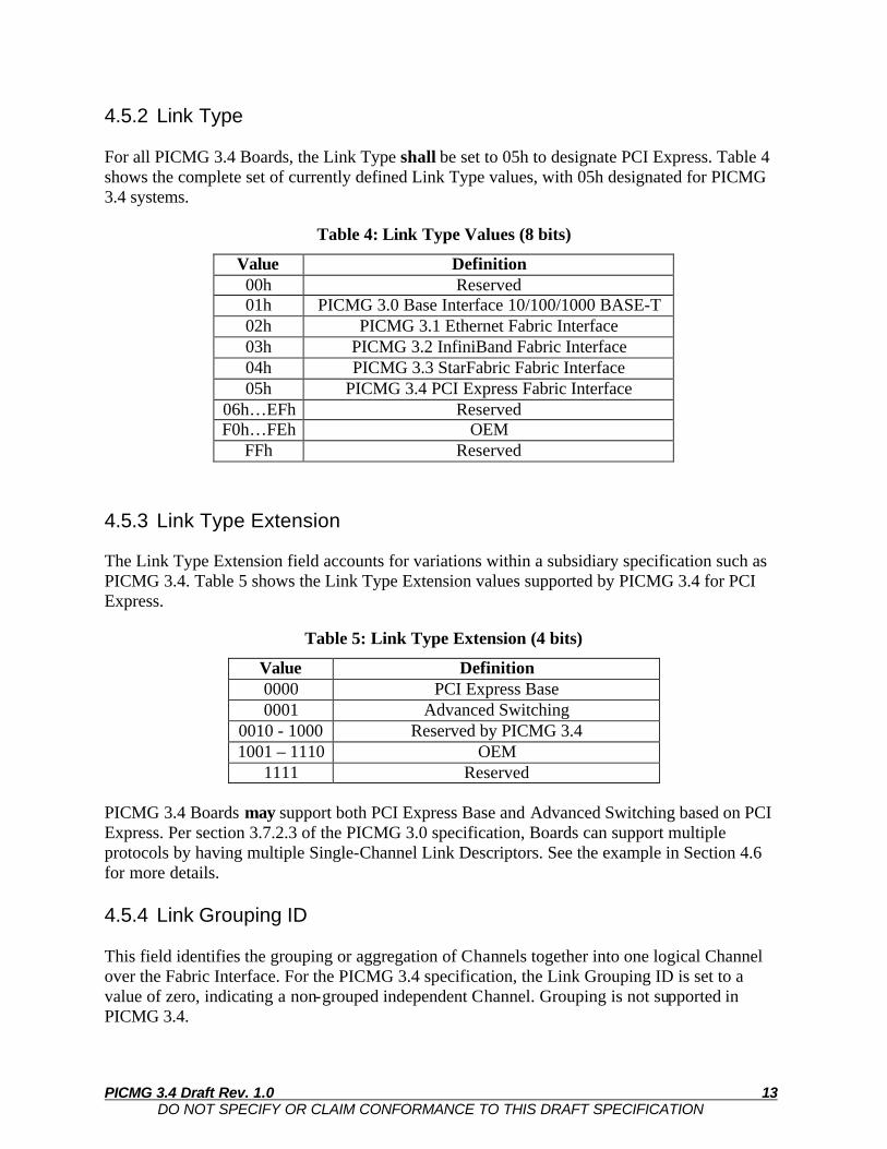
4.5.2 Link Type For all PICMG 3.4 Boards, the Link Type shall be set to 05h to designate PCI Express. Table 4 shows the complete set of currently defined Link Type values, with 05h designated for PICMG 3.4 systems.
Table 4: Link Type Values (8 bits)
Value Definition 00h Reserved 01h PICMG 3.0 Base Interface 10/100/1000 BASE-T 02h PICMG 3.1 Ethernet Fabric Interface 03h PICMG 3.2 InfiniBand Fabric Interface 04h PICMG 3.3 StarFabric Fabric Interface 05h PICMG 3.4 PCI Express Fabric Interface
06h…EFh Reserved F0h…FEh OEM
FFh Reserved 4.5.3 Link Type Extension The Link Type Extension field accounts for variations within a subsidiary specification such as PICMG 3.4. Table 5 shows the Link Type Extension values supported by PICMG 3.4 for PCI Express.
Table 5: Link Type Extension (4 bits)
Value Definition 0000 PCI Express Base 0001 Advanced Switching
0010 - 1000 Reserved by PICMG 3.4 1001 – 1110 OEM
1111 Reserved PICMG 3.4 Boards may support both PCI Express Base and Advanced Switching based on PCI Express. Per section 3.7.2.3 of the PICMG 3.0 specification, Boards can support multiple protocols by having multiple Single-Channel Link Descriptors. See the example in Section 4.6 for more details. 4.5.4 Link Grouping ID This field identifies the grouping or aggregation of Channels together into one logical Channel over the Fabric Interface. For the PICMG 3.4 specification, the Link Grouping ID is set to a value of zero, indicating a non-grouped independent Channel. Grouping is not supported in PICMG 3.4.

PICMG 3.4 Draft Rev. 1.0 14 DO NOT SPECIFY OR CLAIM CONFORMANCE TO THIS DRAFT SPECIFICATION
4.6 Example Interface Information As an example, assume that a PCI Express PICMG 3.4 board is implemented using Fabric Interface Channel 2, with Port 0 and Port 1 enabled. Also assume that the system supports PCI Express Base and Advanced Switching. For this example, there would be two Link Descriptors in the Board Connectivity Record.
Table 6: Example 1 Port FRU Information
CHANNEL 2 Port 2: Disabled Port 3: Disabled Port 0: PCI Express Base or AS 2.5Gb SerDes Port 1: PCI Express Base or AS 2.5Gb SerDes
Field Value Description Link Designator 0011 0100 0010b Channel Number=2; Interface=Fabric; Port 0,1 enabled Link Type 0000 0101b Link Type = PICMG 3.4 PCI Express Link Type Extension 0000b Link Extension = PCI Express Base Link Grouping ID 0000 0000b Link Grouping ID = Independent Link Designator 0011 0100 0010b Channel Number=2; Interface=Fabric; Port 0,1 enabled Link Type 0000 0101b Link Type = PICMG 3.4 PCI Express Link Type Extension 0001b Link Extension = Advanced Switching Link Grouping ID 0000 0000b Link Grouping ID = Independent
4.7 E-Keying and Link Width Negotiation As discussed earlier, PICMG 3.4 Boards and systems may support x1, x2, or x4 implementations. In order for PCI Express Boards to interoperate, Boards must be designed to use Link Width Negotiation in order to match the widths between the point-to-point links between two boards. For example, if Board A supports x4, and is connected to Board B, which only supports x1, the point-to-point connection between these Boards must use a x1 connection. However, if Board A in an ATCA Shelf uses an E-Key indicating x4 support while Board B uses an E-Key indicating x1 support, there will be a mismatch and the Shelf Manager will not enable the interface between the Boards. Due to this requirement, all PICMG 3.4 Boards shall use multiple E-Keys to designate all of the capabilities of the Board. Boards that support x4 implementations shall include E-Keys showing x1 and x2 support as well. Boards that support x2 implementations shall include E-Keys showing x1 support as well. In the example below, an x4 capable PCI Express Base Board using Channel 9 must include three E-Keys indicating its full capabilities. When using multiple E-Keys, all PICMG 3.4 Boards should provide the E-Keys in preferred order, such that the Shelf Manager tries to match to the most preferred E-Key first. The lower priority E-Keys would then only be used when the higher priority E-Keys do not match. In the example, an x4 Board provides the x4 E-Key first, the x2 E-Key second, and the x1 E-Key last.

PICMG 3.4 Draft Rev. 1.0 15 DO NOT SPECIFY OR CLAIM CONFORMANCE TO THIS DRAFT SPECIFICATION
Table 7: Example 2 x4 PCI Express Implementation
CHANNEL 9 Port 2: PCI Express Base 2.5Gb SerDes Port 3: PCI Express Base 2.5Gb SerDes Port 0: PCI Express Base 2.5Gb SerDes Port 1: PCI Express Base 2.5Gb SerDes
OR Port 2: Disabled Port 3: Disabled Port 0: PCI Express Base 2.5Gb SerDes Port 1: PCI Express Base 2.5Gb SerDes
OR Port 2: Disabled Port 3: Disabled Port 0: PCI Express Base 2.5Gb SerDes Port 1: Disabled
Description Value Description Link Designator 1111 0100 1001b Channel Number=9; Interface=Fabric; Port 0,1,2,3 enabled Link Type 0000 0101b Link Type = PICMG 3.4 PCI Express Link Type Extension 0000b Link Extension = PCI Express Base Link Grouping ID 0000 0000b Link Grouping ID = Independent Link Designator 0011 0100 1001b Channel Number=9; Interface=Fabric; Port 0,1 enabled Link Type 0000 0101b Link Type = PICMG 3.4 PCI Express Link Type Extension 0000b Link Extension = PCI Express Base Link Grouping ID 0000 0000b Link Grouping ID = Independent Link Designator 0001 0100 1001b Channel Number=9; Interface=Fabric; Port 0 enabled Link Type 0000 0101b Link Type = PICMG 3.4 PCI Express Link Type Extension 0000b Link Extension = PCI Express Base Link Grouping ID 0000 0000b Link Grouping ID = Independent
4.8 Shelf Manager PICMG 3.4 Boards shall implement the Shelf Manager control as defined by PICMG 3.0 specification, section 3.3.
4.9 Base Interface Requirements The Base Interface is an optional Ethernet interface included in the PICMG 3.0 specification for network management services based on the TCP/IP protocol suite. Examples of such services include remote booting protocols and storage services such as NFS. The Base Interface is provided for fabric technologies that do not support the IP protocol. It may also be used to implement a unified management interface across a hybrid set of PICMG 3.0 Boards.
• PCI Express Base does not support IP services and PICMG 3.4 Node, Mesh-Enabled, and Hub Boards using these two technologies shall implement the Base Interface.
• Advanced Switching based on PCI Express supports IP services and PICMG 3.4 Node Mesh-Enabled, and Hub Boards developed with this technology may implement the Base Interface.

PICMG 3.4 Draft Rev. 1.0 16 DO NOT SPECIFY OR CLAIM CONFORMANCE TO THIS DRAFT SPECIFICATION
• PICMG 3.4 Advanced Switching Hub Boards should implement an interface to the Dedicated ShMC by mapping 10/100/1000BaseT connections to Base Channel 1.