pick-o-mat automated assembly system: high …
TRANSCRIPT

PICK-O-MAT
PM 1100 PM 1500
AUTOMATED ASSEMBLY SYSTEM | PICK-O-MAT AUTOMATED ASSEMBLY SYSTEM
PICK-O-MAT AUTOMATED ASSEMBLY SYSTEM: HIGH-PERFORMANCE AND EASY TO INTEGRATE
THE SIZES
Handling module Lifting module Pressing module
Available in two sizes, the PM 1100 and PM 1500 are the ideal basic machines for your specific application.
204

The Pick-o-Mat is in a class of its own: the electromechanical automated assembly system unites a rotary indexing table with up to 24 handling, pressing and lifting modules, which are synchronised via a central drive. Different stroke variants can be combined easily. The elegant and powerful drive solution works without pneumatic handling mechanisms and is available in two sizes.
ADVANTAGES
· Automated assembly system with rotary indexing table and up to 24 integrated handling, pressing and lifting modules
· Central cam drive for all module movements
· Powerful, affordable and easy-to-integrate complete solution also available on request with base plate, base frame (SR or SK model range) and control system
Assembly of small parts at Hammermeister Sondermaschinenentwicklung GmbH
205

Drive disk Horizontal stroke
Drive diskVertical stroke
Cam operated central drive
Motor of the central drive
Rotary indexing table with motor
T-grooves for radial alignment
Encoder
Rotating plate as per customer specifications
Monitored crash protection
TECHNICAL DATA
Repeatability: ± 0.03 mm
Max. horizontal stroke (handling module): 140 mm
Max. vertical stroke (handling module): 50 mm
Mechanical standard speeds/min. at 50 Hz:
32*, 48*, 60*, 75*
Max. handling weight (kg): 2
Drive of the rotary table and central unit:
AC brake motor
Motor voltage: 400 V / 50 Hz or 440-480 V / 60 Hz
Drive output: 0.25 - 0.37 kW
Monitoring sensor: 24 V, PNP N/O contact
* Reduction possible with frequency converter.
Figure 1: Pos. cam cylinder: 0°Pos. manipulator: down-retracted
Figure 2: Pos. cam cylinder: 75° Pos. manipulator: up-retracted
Figure 3: Pos. cam cylinder: 112° Pos. manipulator: up-extended
Figure 4: Pos. cam cylinder: 180° Pos. manipulator: down-extended
360° BARREL CAM ROTATION = 4 VERTICAL STROKES + 2 HORIZONTAL STROKES = 1 COMPLETE CYCLE
A 360° rotation of the barrel cam of the central drive generates a complete cycle of the pick-and-place units. Lifting and pressing modules are moved by the lower drive disk (only).
CENTRAL DRIVE
206

POM AUTOMATED ASSEMBLY SYSTEM
OPTIONS AND ADJUSTMENTS
To complete your Pick-o-Mat, plates and base frames can be manufactured as per your drawings
EF2 frequency converter control system for fast and simple start-up
STANDARDISED YET INDIVIDUAL
Alongside a large variety of parameters for adapting our standard components, we can manufacture the following components for adapting or completing your Pick-o-Mat in accordance with your drawings:
· Base frame with levelling elements for stable mounting of the basic machine (see also SR/SK model line)
· Base plate for mounting the central drive and your additional devices such as feeder equipment
· Rotary plate for mounting your workpiece carriers in accordance with your drilling pattern and with the desired outer diameter
· Adapter plate on the handling module for mounting your grippers
Looking at the CAD models of all standard modules of the Pick-o-Mat which have been made available on our website allows fast and secure project planning and design.
FAST START-UP AND GUARANTEED QUALITY
Every Pick-o-Mat is subjected to comprehensive testing and measurements prior to shipping, guaranteeing seamless integration into your complete system.
SIMPLE AND SECURE CONTROL
An encoder mounted on the cam axis of the central drive transmits the current position. The direct relationship between the rotation angle of the cam and the position of the gripper enables easy and secure control of all other modules within the rotary table. Alongside the compact control and monitoring components of-fered by WEISS, the integrated mechanical overload protec-tion ensures the safe operation of your machine.
AFFORDABLE AND QUICKLY AVAILABLE
Thanks to the combination of WEISS components manufac-tured in large numbers and your individual automated assem-bly systems, we can deliver the entire machine in six weeks at an unbeatable price.
Application example for the assembly of small parts at Hammer-meister Sondermaschinenentwicklung GmbH
207

PM 1100TECHNICAL DATA
Rotary indexing table, basis: TC 320T (for specifications, see TC-T rotary indexing tables)
Max. number of modules: 16
Number of stations on rotary table: 4 to 36
Diameter of stationary module plate: 760 mm
Diameter of rotary plate: Standard 1050 mm (other diameters possible)
Available base frames: SR 0200B or SK 0300B
The maximum number of modules and the smallest spacing distance possible must be reviewed for eachapplication from a design point of view and depend on the type of module and the desired sequence.
Customer‘s mounting fixture or base plate
Drilling pattern with mounting hole in the base plate
Supporting plate
appr
ox. 1
040
appr
ox. 4
12
208

X
X
POM AUTOMATED ASSEMBLY SYSTEM
If required, the vertical guide assembly can be mounted at two heights with a difference of 33 mm (see figures for assembly 1 and assembly 2).
For all stroke variants, the stroke including adjustment limits can only lie within the grey shaded area. For pre-adjustment prior to assembly, the setting dimensions H and V must be specified when ordering. The final adjustment is performed by the customer after fitting the gripper.
Maximum extra weight: 2 kg (depending on speed and number of modules)
Standard strokes:
Vertical stroke [mm] 30 40 50
of which linear without crossover (approx.) [mm] 25 30 37.5
Horizontal stroke [mm] 80 90* 100 120 140
of which linear without crossover (approx.) [mm] 65 75 85 100 115
* The horizontal stroke of 90 mm can only be realised in combination with vertical strokes of 40 mm and 50 mm.
Assembly 1 – bottom vertical railPosition of the handling unit: top – outside
Assembly 2 – top vertical railPosition of the handling unit: top – outside
Standard adapter plate (40 x 64 x 8 mm) with drilling pattern (2x DRM 5 H7; 2x M5) for mounting to the guide (customised configurations possible)
TECHNICAL DATA
PM 1100E HANDLING MODULE
Centre of table
View X (1:2)
209

X
Z
A
PM 1100H LIFTING MODULEUSING THE LIFTING MODULEThe lifting module can be used for the vertical movement of a test medium. In order to avoid crash situations, the test medium must contain a spring-mounted overload protection system that permits max. 50 N spring force and at least 71 mm spring travel.
METHOD OF FUNCTIONINGThe lifting module moves simultaneously with the horizontal stroke of the handling module. The downward movement is performed synchronously with the retraction of the handling module.
Maximum weight to be moved: 1.5 kg
Stroke dependencies [mm]:
Vertical stroke of the handling module 30.0 ≥ 40.0
Stroke of the lifting module 58.3 70.0
Bottom position (distance A) 100.0 94.0
TECHNICAL DATA
View X
210
X
Z
A
POM AUTOMATED ASSEMBLY SYSTEM
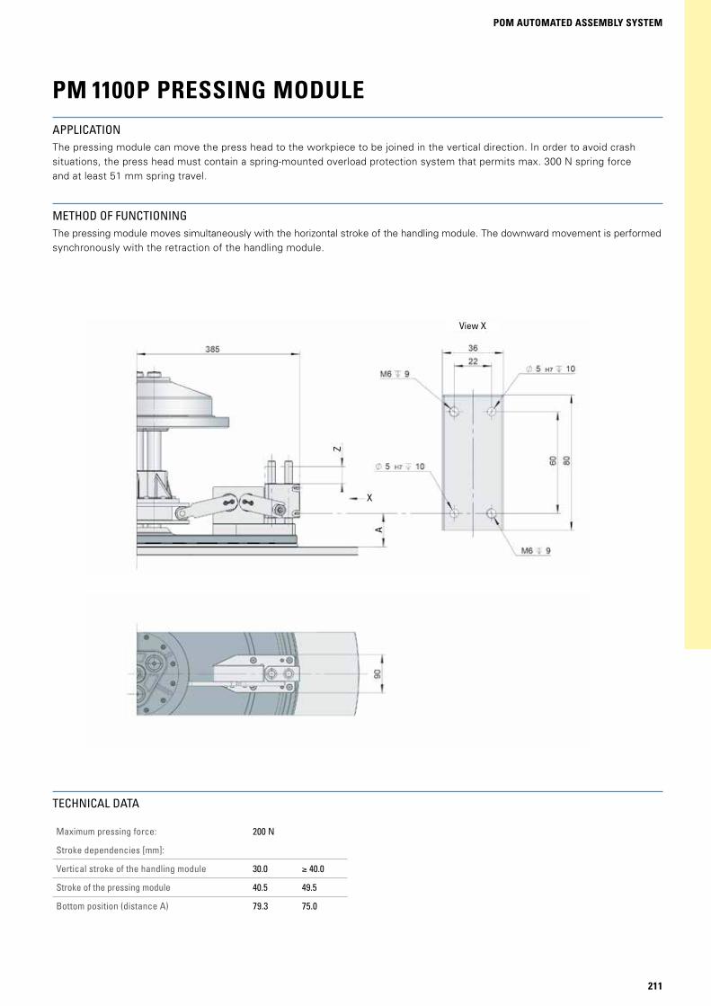
PM 1100P PRESSING MODULEAPPLICATIONThe pressing module can move the press head to the workpiece to be joined in the vertical direction. In order to avoid crash situations, the press head must contain a spring-mounted overload protection system that permits max. 300 N spring force and at least 51 mm spring travel.
METHOD OF FUNCTIONINGThe pressing module moves simultaneously with the horizontal stroke of the handling module. The downward movement is performed synchronously with the retraction of the handling module.
Maximum pressing force: 200 N
Stroke dependencies [mm]:
Vertical stroke of the handling module 30.0 ≥ 40.0
Stroke of the pressing module 40.5 49.5
Bottom position (distance A) 79.3 75.0
TECHNICAL DATA
View X
211

X
PM 1500TECHNICAL DATA
Rotary indexing table, basis: TR 1100A (for specifications, see TR rotary indexing tables)
Max. number of modules: 24
Number of stations on rotary table: 6 to 36
Diameter of stationary module plate: 1210 mm
Diameter of rotary ring: Standard 1500 mm (other diameters possible)
Possible base frames: SR 0300B or SK 0300B
The maximum number of modules and the smallest spacing distance possible must be reviewed for eachapplication from a design point of view and depend on the type of module and the desired sequence.
Detail X
Recess in the base plate
Recess + drilling pattern TR 1100A
212

X
POM AUTOMATED ASSEMBLY SYSTEM
Assembly 1 – bottom vertical railPosition of the handling unit: top – outside
Assembly 2 – top vertical railPosition of the handling unit: top – outside
TECHNICAL DATA
Maximum extra weight: 2kg (depending on speed and number of modules)
Standard strokes:
Vertical stroke [mm] 30 40 50
of which linear without crossover (approx.) [mm] 25 30 37.5
Horizontal stroke [mm] 80 90* 100 120 140
of which linear without crossover (approx.) [mm] 65 75 85 100 115
* The horizontal stroke of 90 mm can only be realised in combination with vertical strokes of 40 mm and 50 mm.
PM 1500E HANDLING MODULE
If required, the vertical guide assembly can be mounted at two heights with a difference of 33 mm (see figures for assembly 1 and assembly 2).
For all stroke variants, the stroke including adjustment limits can only lie within the grey shaded area. For pre-adjustment in the factory, the adjustment dimensions H and V must be specified when ordering. The final adjustment is performed by the custo-mer after fitting the gripper.
Centre of table
View X (1:2)
Standard adapter plate (40 x 64 x 8 mm) with drilling pattern (2x DRM 5 H7; 2x M5) for mounting to the guide (customised configurations possible)
213

PM 1500H LIFTING MODULEUSING THE LIFTING MODULEThe lifting module can be used for vertical movement of test equipment. In order to avoid crash situations, the test medium must contain a spring-mounted overload protection system that permits max. 50 N spring force and at least 71 mm spring travel.
METHOD OF FUNCTIONINGThe lifting module moves simultaneously with the horizontal stroke of the handling module. The downward movement is performed synchronously with the retraction of the handling module.
TECHNICAL DATA
Maximum weight to be moved: 1.5 kg
Stroke dependencies [mm]:
Vertical stroke of the handling module 30.0 ≥ 40.0
Stroke of the lifting module 58.3 70.0
Bottom position (distance A) 100.0 94.0
View X
214

POM AUTOMATED ASSEMBLY SYSTEM
PM 1500P PRESSING MODULEAPPLICATIONThe pressing module can move the press head to the workpiece to be joined in the vertical direction. In order to avoid crash situ-ations, the press head must contain a spring-mounted overload protection system that permits max. 300 N spring force and at least 51 mm spring travel.
METHOD OF FUNCTIONINGThe pressing module moves simultaneously with the horizontal stroke of the handling module. The downward movement is performed synchronously with the retraction of the handling module.
TECHNICAL DATA
Maximum pressing force: 200 N
Stroke dependencies [mm]:
Vertical stroke of the handling module 30.0 ≥ 40.0
Stroke of the pressing module 41.5 50.05
Bottom position (distance A) 75-95 75-95
The stroke position can be adjusted by means of a threaded bar.
View X
215

Desired delivery date: _______________________________________Phone: _________________________ Fax: _______________________E-Mail: _____________________________________________________
Company: ___________________________________________________Name: _____________________________________________________Country: ____________________________________________________
MACHINE DESIGN PICK-O-MATFax to: +49 (0) 6281 5208-99 or just fill in the form online: www.weiss-international.com
Enquiry Attachment to order
Dear customer,thank you for your interest in our Pick-o-Mat machine. Please answer the following questions, to ensure we optimise the design of the system to suit your application. Please also fill out the „Module arrangement and setting dimensions“ form on page 217.
PM 1100Z with TC 320T PM 1500Z with TR 1100A Cycles per minute: ___________________________________
Vertical stroke: 30 mm 40 mm (50 mm possible through special handling module)Encoder:
Single-turn absolute encoder (standard) Customer-specific as per drawing no.: __________________ None
Configuration of the central unit Handling module
Number of modules: ___________________________________Max. handling weight in kg: _____________________________ Strokes, arrangement and setting dimensions as per formAdapter plate:
Standard (see catalogue for drilling pattern) As per drawing no.: _________________________________ No adapter plate
Colour: RAL 7035 (standard) or RAL ________________
Indexing: ______________________________________________Weight per station in kg: ________________________________Effective diameter of the centre of mass in mm: ___________Position of motor
Standard (TC 320T – inside on the side; TR 1100A – inside at the bottom)
Other, as per drawing no.: ___________________________Colour: RAL 7035 (standard) or RAL ________________Dimensions and additional processing of the rotating plate as per drawing no.: _______________________________________
Standard material of rotating plate (AlMg4.5Mn) Standard surface treatment (naturally anodised) Deviations from standard:
Material: ______________________________________________Surface treatment: _____________________________________
Type of rotary table Lifting module
Number of modules: ____________________________________Max. weight to be lifted in kg: ____________________________Drilling pattern of the mounting surface:
Standard As per drawing no.: _________________________________
Colour: RAL 7035 (standard) or RAL ________________
Pressing module
Number of modules: ____________________________________Pressing force in N (max. permitted 200 N): ________________
Max. stroke in mm: __________________________________Drilling pattern of the mounting surface:
Standard (see catalogue for drilling pattern) As per drawing no.: _________________________________
Colour: RAL 7035 (standard) or RAL ________________
Drive motor 230/400 V 50 Hz (standard) Drive motor special voltage in V:______________________ Customer drive motor (additional)
Electric drives (central unit and rotary table) Base frame
No base frame Round SR (SR 200B or SR 300B) Square SK (SK 300B) Special base frame as per drawing: ___________________
Height floor – base plate in mm: __________________________Colour: RAL 7035 (standard) or RAL _________________
WEISS EF2 rotary table control system (frequency converter) No control system
Control system of the central unit and of the rotary table Base plate
Dimensions, additional processing, material and surface treat-ment of the base plate as per drawing no.: _____________
For technical enquiries
216

POM AUTOMATED ASSEMBLY SYSTEM
MODULE ARRANGEMENT AND SETTING DIMENSIONSFax to: +49 (0) 6281 5208-99 or just fill in the form online: www.weiss-international.com
Station Module1 h p l
Horizontal stroke [mm] (handling module only)2
Setting dimension horizontal H [mm]3
Vertical stroke [mm]4 Setting dimension vertical V [mm]3
1
2
3
4
5
6
7
8
9
10
11
12
13
14
15
16
17
18
19
20
21
22
23
24
25
26
27
28
29
30
31
32
33
34
35
36
Customer: ______________________________________________Order number: ________________________________________Date: ________________________________________________Drawing number of the assembly drawing: ______________________________________________________Originator: ____________________________________________ Size of the POM: PM 1100 PM 1500Indexing of the rotary table: ____________________
1 h=handling module, p=pressing module, l=lifting module. Please assign the modules to the corresponding station. If no gripper plate is required, distance H is up to the front side of the guide rail. 2 Stroke variants: 80/90/100/120/140 3 The values for the setting dimensions H and V are always specified in the „upper/extended“ position.4 Stroke variants: handling: 30 /40 /50; lifting: 58.3 /70; pressing: PM1100P: 40.5 / 49.5; PM1500P: 41 / 50.5
217
