piccolo c2000 mcus enable the next generation of low-cost
TRANSCRIPT
C2000™ MCUs enable the next generation of low-cost, dual-axis servo drives
Brian Fortman C2000™ MarketingTexas Instruments

I 2 C2000™ MCUs enable the next generation of low-cost, dual-axis servo drives July 2020
As factory automation continues its rapid adoption of precision motion control in industrial machines, the number of servo motors and servo drives used in these applications is skyrocketing.
Some analysts have characterized the servo drive market as “unbounded” as the
applications expand. This is not surprising as previous manual processes become
automated: the mechanical power capability of today’s servo motors can be a practical
replacement for pneumatic and hydraulic-based actuation.
Motion control and servo drive advancements –
enabled by servo drive and servo motor hardware
enhancements such as the transition of inverter
switches away from insulated gate bipolar
transistors (IGBTs) toward higher-speed gallium
nitride (GaN) and higher-power silicon carbide (SiC)
technology – remain essential for competing in the
global economy. The market dynamics also remain
extremely competitive. Suppliers seek advantages
for their servo drive lineups in system-level criteria
including control performance, connectivity, ease of
use and cost.
Higher performance and higher precision control
will always be sought after for some machine
functions. However, given the strides already made
in digital drive control performance, the greater
challenge today is the cost of “standard” motion
performance for a machine’s application, rather
than the maximum attainable control bandwidth for
speed and position loops. And since most industrial
automation machines have multiple motor axes
of control, a better metric to consider is the cost-
per-axis for such performance. Since some drive
electronics functions (and therefore their costs) can
be shared across axes, in some cases it makes
sense to consider servo drives that can support two
axes instead of the more traditional single motor.
With the release of the F28004x and F28002x
series of C2000™ microcontrollers (MCUs), Texas
Instruments (TI) has enabled a new value point
for dual-axis drives that also delivers very robust
motion-control performance. The value comes not
only from the achievable control performance and
ability to drive two motors concurrently, but also
from the high degree of on-chip integration of other
key electronic system functions.
I 3 C2000™ MCUs enable the next generation of low-cost, dual-axis servo drives July 2020
In this white paper, I will show the superset F28004x
features that enable support for dual axes, with
control technology that delivers unprecedented
motion control performance and the opportunity
to further reduce the bill of materials by using both
new and legacy features integrated onto a real-time
controller.
Integrated peripherals support
dual-axis drives
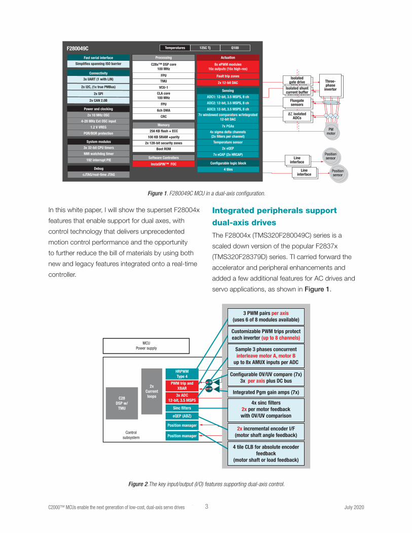
The F28004x (TMS320F280049C) series is a
scaled down version of the popular F2837x
(TMS320F28379D) series. TI carried forward the
accelerator and peripheral enhancements and
added a few additional features for AC drives and
servo applications, as shown in Figure 1.
Line Interface
FluxgateSensors
DS Isolated ADCs
Isolated ShuntCurrent Buffer
Isolated Gate Drive
Position Sensor
Line Interface
Position Sensor
PMMotor
Three-Phase
Invertor
Line interface
Fluxgatesensors
∆Σ isolated ADCs
Isolated shuntcurrent buffer
Isolated gate drive
Position sensor
Line interface
Position sensor
PMmotor
Three-phase
invertor
ADC1: 12-bit, 3.5 MSPS, 8 ch
Sensing
F280049C
4 tiles
Configurable logic block
ADC2: 12-bit, 3.5 MSPS, 8 ch
ADC3: 12-bit, 3.5 MSPS, 8 ch
7x windowed comparators w/integrated12-bit DAC
7x PGAs
Temperature sensor
2x eQEP
7x eCAP (2x HRCAP)
System modules
Power and clocking
Temperatures 125C Tj Q100
3x 32-bit CPU timers
NMI watchdog timer
192 interrupt PIE
4x sigma delta channels(2x filters per channel)
C28x™ DSP core100 MHz
Processing
InstaSPIN™ FOC
FPU
TMU
VCU-1
FPU
6ch DMA
256 KB flash + ECC
100 KB SRAM +parity
2x 128-bit security zones
Boot ROM
CLA core100 MHz
8x ePWM modules16x outputs (16x high-res)
Actuation
Fault trip zones
2x 12-bit DAC
Connectivity
2x I2C, (1x true PMBus)
2x SPI
2x CAN 2.0B
2x 10 MHz OSC
4-20 MHz Ext OSC input
1.2 V VREG
3x UART (1 with LIN)
Memory
CRC
Software Controllers
Debug
cJTAG/real-time JTAG
POR/BOR protection
Fast serial interface
Simplifies spanning ISO barrier
Figure 2.The key input/output (I/O) features supporting dual-axis control.
MCUPower supply
Controlsubsystem
PWM trip andXBAR
3x ADC12-bit, 3.5 MSPS
Sinc filters
eQEP (ABZ)
Position manager
Position manager
Line Interface
FluxgateSensors
DS Isolated ADCs
Isolated ShuntCurrent Buffer
Isolated Gate Drive
Position Sensor
Line Interface
Position Sensor
PMMotor
Three-Phase
InvertorDVD
DVD
Line Interface
FluxgateSensors
DS Isolated ADCs
Isolated ShuntCurrent Buffer
Isolated Gate Drive
Position Sensor
Line Interface
Position Sensor
PMMotor
Three-Phase
Invertor
2xCurrentloopsC28
DSP w/TMU
Sample 3 phases concurrentinterleave motor A, motor B
up to 8x AMUX inputs per ADC
4 tile CLB for absolute encoderfeedback
(motor shaft or load feedback)
4x sinc filters2x per motor feedbackwith OV/UV comparison
3 PWM pairs per axis(uses 6 of 8 modules available)
Customizable PWM trips protecteach inverter (up to 8 channels)
Configurable OV/UV compare (7x)3x per axis plus DC bus
2x incremental encoder I/F(motor shaft angle feedback)
Integrated Pgm gain amps (7x)
HRPWMType 4
Figure 1. F280049C MCU in a dual-axis configuration.
I 4 C2000™ MCUs enable the next generation of low-cost, dual-axis servo drives July 2020
Let’s have a closer look at how the configuration of
the F28004x series enables the control of two servo
motors concurrently. Several of the key features
supporting dual axis applications are highlighted in
Figure 2 below.
Inverter actuation through C2000
fourth-generation ePWM modules
A common two-level three-phase inverter used for a
permanent magnet synchronous motor (PMSM) or
an alternating current induction (ACI) motor requires
two switches in a half-bridge configuration on each
of the three legs.
The pulse-width modulators (PWMs) act as
complementary pairs to ensure the correct
management of the high- and low-side switches
of one leg.
High-performance deadband features of the PWMs
are especially helpful here to avoid shoot-through.
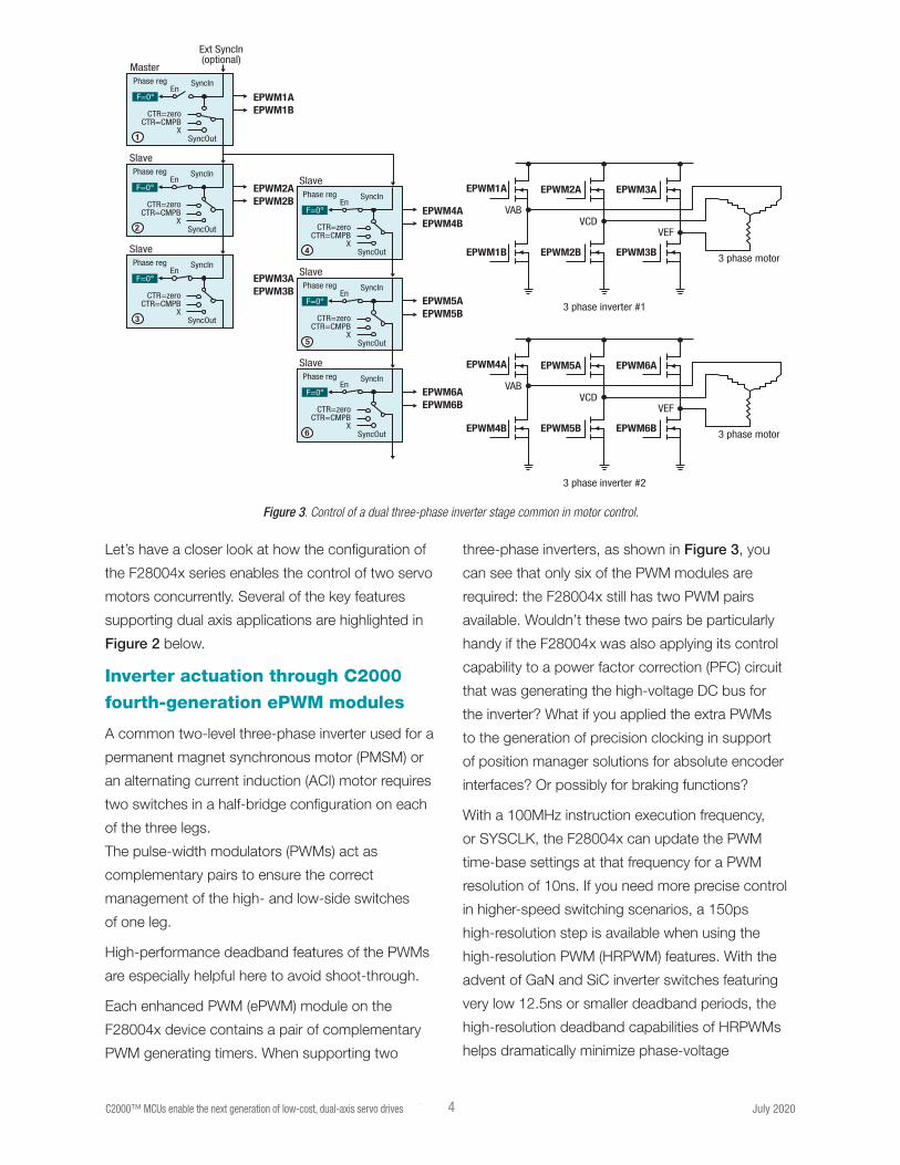
Each enhanced PWM (ePWM) module on the
F28004x device contains a pair of complementary
PWM generating timers. When supporting two
three-phase inverters, as shown in Figure 3, you
can see that only six of the PWM modules are
required: the F28004x still has two PWM pairs
available. Wouldn’t these two pairs be particularly
handy if the F28004x was also applying its control
capability to a power factor correction (PFC) circuit
that was generating the high-voltage DC bus for
the inverter? What if you applied the extra PWMs
to the generation of precision clocking in support
of position manager solutions for absolute encoder
interfaces? Or possibly for braking functions?
With a 100MHz instruction execution frequency,
or SYSCLK, the F28004x can update the PWM
time-base settings at that frequency for a PWM
resolution of 10ns. If you need more precise control
in higher-speed switching scenarios, a 150ps
high-resolution step is available when using the
high-resolution PWM (HRPWM) features. With the
advent of GaN and SiC inverter switches featuring
very low 12.5ns or smaller deadband periods, the
high-resolution deadband capabilities of HRPWMs
helps dramatically minimize phase-voltage
Figure 3. Control of a dual three-phase inverter stage common in motor control.
EPWM4A
EPWM4B EPWM5B
EPWM5A
EPWM6B
3 phase inverter #2
3 phase motor
VABVCD
VEF
EPWM6A
EPWM4AEPWM4B
EPWM5AEPWM5B
EPWM6AEPWM6B
EPWM1AEPWM1B
EPWM2AEPWM2B
EPWM3AEPWM3B
EPWM1A
EPWM1B EPWM2B
EPWM2A
EPWM3B
3 phase inverter #1
3 phase motor
VABVCD
VEF
EPWM3ASlavePhase reg SyncIn
SyncOut
En
4
CTR=zeroCTR=CMPB
X
F=0°
SlavePhase reg SyncIn
SyncOut
En
5
CTR=zeroCTR=CMPB
X
F=0°
SlavePhase reg SyncIn
SyncOut
En
6
CTR=zeroCTR=CMPB
X
F=0°
Master
Ext SyncIn(optional)
Phase reg SyncIn
SyncOut
En
1
CTR=zeroCTR=CMPB
X
F=0°
SlavePhase reg SyncIn
SyncOut
En
2
CTR=zeroCTR=CMPB
X
F=0°
SlavePhase reg SyncIn
SyncOut
En
3
CTR=zeroCTR=CMPB
X
F=0°

I 5 C2000™ MCUs enable the next generation of low-cost, dual-axis servo drives July 2020
ringing, sinusoidal distortions and electromagnetic
interference.
Customizable inverter protection through flexible PWM trip capability
Placing the PWM outputs into a known protected
state using the ePWM trip-zone capability protects
the inverter. This feature can be particularly useful if
you need a torque-off condition when using the trip
in one-shot mode.
Applying the supported cycle-by-cycle tripping
mechanisms may allow even more sophisticated
ways to keep the equipment running without
completely shutting down. In addition, there are
multiple potential sources for driving a PWM trip.
These sources include an external signal for on-chip
qualification and inversion as well as integrated,
high-speed analog comparators and on-chip sigma-
delta filter comparators. As many as eight channels
of trip input and PWM crossbar resources are
available, so it’s possible to reserve four channels of
trips for each of the two inverters. Every F28004x
PWM trip module also includes a selection of
Boolean logic configurations in the digital compare
module that can further qualify the trip action.
High-performance analog conversion of three phases concurrently
Reducing the overall current-loop time is critical
for high-performance servo control. The analog-
to-digital (ADC) conversion time has a significant
impact on the total current-loop time. It would
seem like sampling each motor-phase current
on two motors would dominate the current-loop
time. However, the high-performance ADCs on the
F28004x include many features that minimize the
impact on a dual-motor, dual-current loop.
For example, the F28004x has three ADCs that can
use a common start-of-conversion trigger, enabling
the measurement of all three phases at precisely the
same time. Only two ADCs would require additional
sampling, or the CPU would have to algorithmically
derive the third phase value, potentially introducing
errors in the control and increasing the latency in
CPU field-oriented control (FOC) processing. The
three 12-bit ADCs can complete the sampling and
conversions concurrently in only 290ns.
Also consider that each of the three F28004x ADCs
deliver these 3.5MSPS while also delivering 11.1
effective number of bits (ENOB) of dynamic range.
Because of the flexible start-of-conversion triggering
ability, the same three ADCs can alternately sample
the three phases of each motor’s current. By
suitably staggering the start of conversion for each
motor, the time it takes to close the current loop for
a dual-axis system is not double the length of time
needed to complete a single current loop. In fact,
the loop time is the same, whether supporting single
or dual axes.
As many as 21 analog multiplexed inputs
Each ADC has at least nine multiplexed analog
input options on the 100-pin quad flat package
(QFP) and at least four potential analog inputs on
the 7mm-by-7mm 56-pin quad flat no-lead (QFN)
package. This configuration provides flexibility to
support the interleaved three-phase sampling of at
least four different sets of current and/or voltage
sensing, even on the tiniest device in the F28004x
series, with several additional analog inputs for DC
bus, temperature monitoring and perhaps other less
time-critical signals.
Four sigma-delta filters
The F28004x supports dual axes in high voltage
systems as well. When delta-sigma modulators are
used to sense motor-phase currents, the resulting
digital signals cross the air gap to the cold-side
where they must be filtered for use in the control
I 6 C2000™ MCUs enable the next generation of low-cost, dual-axis servo drives July 2020
algorithms. TI’s AMC130x delta-sigma modulators
are a good option but still require filtering to use
them for motion control. Like previous MCUs, the
F28004x series features digital sinc filtering on-
chip to support these external ADCs. In fact, with
four total channels of the digital filters on-chip,
it’s possible to route two phases of the sampled
current information of each motor directly to the
F28004x. In this case, the CPU can use the two
input phases to algorithmically derive the third phase
values. Recall that each sigma-delta input channel
includes a parallel digital comparison path that when
configured can trip the PWMs in
overcurrent situations.
Motor shaft position feedback through two eQEPs
Whether it’s a dual-channel motor-shaft position
or dual channels of absolute encoder load-angle
feedback, the F28004x series can decode all four
feedback paths simultaneously. Many servo motors
today come with built-in incremental position
encoders, commonly referred to as ABZ encoders
by the names of their output signals, A, B and Z,
to feed back the motor-shaft angle once you know
the index. Because the F28004x includes two
standard enhanced quadrature encoder peripherals
(eQEPs) on-chip, handling dual ABZ interfaces is not
a problem. The trend in the industry is to move to
absolute encoders and avoid the indexing problem
altogether. Absolute encoders are especially helpful
for measuring the load angle and a dual-axis drive
will need to support two interfaces to
absolute encoders.
Dual feedback paths of load positions through absolute encoder protocols
The position manager solutions for absolute
encoders leverage a peripheral block on the
F28004x and other C2000 MCUs called the
configurable logic block (CLB). The CLB works with
other peripherals on-chip to create more valuable
functions that otherwise might require external logic
devices such as a complex programmable logic
device (CPLD) or a field-programmable gate
array (FPGA).
In position manager solutions, coupling the CLB
with a serial port creates solutions for EnDat2.2,
bidirectional/serial/synchronous (BiSS), Tamagawa
T-format and other serial encoder standards. The
CLB on the F28004x has enough capability to
implement two channels of most protocols.
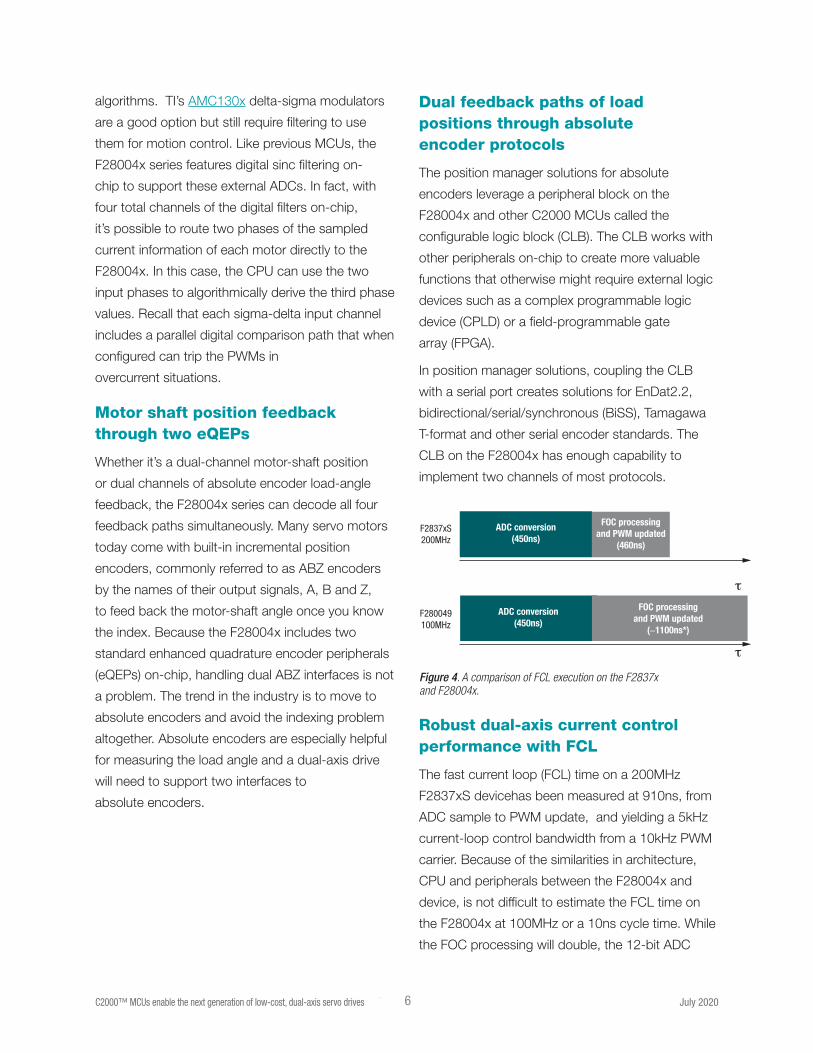
Robust dual-axis current control performance with FCL
The fast current loop (FCL) time on a 200MHz
F2837xS devicehas been measured at 910ns, from
ADC sample to PWM update, and yielding a 5kHz
current-loop control bandwidth from a 10kHz PWM
carrier. Because of the similarities in architecture,
CPU and peripherals between the F28004x and
device, is not difficult to estimate the FCL time on
the F28004x at 100MHz or a 10ns cycle time. While
the FOC processing will double, the 12-bit ADC
Figure 4. A comparison of FCL execution on the F2837x and F28004x.
ADC conversion(450ns)
FOC processingand PWM updated
(460ns)
FOC processingand PWM updated
(∼1100ns*)
F2837xS200MHz
F280049100MHz
ADC conversion(450ns)
τ
τ
Current looptime
PWM update time Max modulation index
Single axis
Dual axes(per axis)
Conditions:• fpwm = 10 KHz• Double sampling, in line• QEP/ABZ position feedback
Results:• Current loop phase margin = 30° • Current loop phase margin = 6.6KHz
F2837xS(1x C28x. 1x CLA)
< 1.0 µs
< 1.0 µs
< 1.6 µs
< 1.6 µs
96 %
96 %
93.6 %
93.6 %
* Estimated
F280049(1x C28x, 1x CLA)
F2837xS(1x C28x. 1x CLA)
F280049(C28x, CLA)

I 7 C2000™ MCUs enable the next generation of low-cost, dual-axis servo drives July 2020
conversion time will not change. See Figure 4.
For a single axis, you can estimate the FCL to
complete in less than 1.6µs on the F28004x series,
which is nearly a full microsecond faster than
traditional current loops. Even on the lower-cost
device, the closed loop current bandwidth provided
by FCL remains at 5kHz on a 10kHz carrier.
However, this white paper is about using the
F28004x in a dual-axis configuration. Previously, I
described how the F28004x series has the peripheral
capability to support two servo motors at the same
time. If you assume that the ground plane of the
control circuits is not shared with the ground planes
of each of the inverter/motor axes, then it’s possible
for a single F28004x to run two independent FCLs
in 1.6µs while still supporting the high-control
bandwidth and double sampling of each axis.
The key lies in interleaving the ADC double sampling
between each motor so that the sampling and
subsequent FOC processing does not need to
happen back to back. In order to maintain the goal
of measuring the currents of each motor during
voltage transitions, there must be a phase difference
between the carriers driving each axis.
For example, if the motor B carrier lags motor A by
a fixed 90 degrees, then the ADC sampling period
is consistent across both motors but interleaved
between them. Using two 100µs carriers, the ADCs
can sample three phases of motor A at time zero,
three phases of motor B at 25µs, a “double sample”
of motor A at 50µs and a double sample of motor B
at 75µs. See Figure 5.
Each ADC sample and conversion is followed by
the C28x CPU performing the FOC algorithm and
updating the PWMs. In this way, the sample-to-PWM
update remains very consistent for each execution,
whether it’s the first or second sample of motor A or
motor B.
Although using shared resources (the ADCs and
the CPU, for example), there is no contention for
these resources with this scheme. Each current-
loop update – and there are four of them happening
in one period, T – takes only 1.6µs. All of the
performance benefits of FCL, like high control
bandwidth and marginal modulation index (M-I)
impact, still apply.
Figure 5. A comparison of FCL execution on the F2837x and F28004x.
T/4 = PWM timing difference between inverters
Other processingF28004x C28FCL ISR
3 Ph samplesIn-A1, In-B1, In-C1
3 Ph samplesIn-A2, In-B2, In-C2
F28004x ADCsfs = 4/T
Motor B
Motor A
sample (n) PWM updateFOC process on C28FCL on F28004x
Double sampling
T = PWM period PWM 1, 2, 3
PWM 4, 5, 6
I 8 C2000™ MCUs enable the next generation of low-cost, dual-axis servo drives July 2020
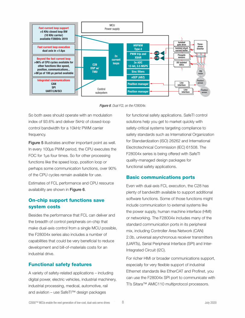
So both axes should operate with an modulation
index of 93.6% and deliver 5kHz of closed-loop
control bandwidth for a 10kHz PWM carrier
frequency.
Figure 5 illustrates another important point as well.
In every 100µs PWM period, the CPU executes the
FOC for 1µs four times. So for other processing
functions like the speed loop, position loop or
perhaps some communication functions, over 90%
of the CPU cycles remain available for use.
Estimates of FCL performance and CPU resource
availability are shown in Figure 6.
On-chip support functions save system costs
Besides the performance that FCL can deliver and
the breadth of control peripherals on-chip that
make dual-axis control from a single MCU possible,
the F28004x series also includes a number of
capabilities that could be very beneficial to reduce
development and bill-of-materials costs for an
industrial drive.
Functional safety features
A variety of safety-related applications – including
digital power, electric vehicles, industrial machinery,
industrial processing, medical, automotive, rail
and aviation – use SafeTI™ design packages
for functional safety applications. SafeTI control
solutions help you get to market quickly with
safety-critical systems targeting compliance to
safety standards such as International Organization
for Standardization (ISO) 26262 and International
Electrotechnical Commission (IEC) 61508. The
F28004x series is being offered with SafeTI
quality-managed design packages for
functional safety applications.
Basic communications ports
Even with dual-axis FCL execution, the C28 has
plenty of bandwidth available to support additional
software functions. Some of those functions might
include communication to external systems like
the power supply, human machine interface (HMI)
or networking. The F28004x includes many of the
standard communication ports in its peripheral
mix, including Controller Area Network (CAN)
2.0b, universal asynchronous receiver transmitters
(UARTs), Serial Peripheral Interface (SPI) and Inter-
Integrated Circuit (I2C).
For richer HMI or broader communications support,
especially for very flexible support of industrial
Ethernet standards like EtherCAT and Profinet, you
can use the F28004x SPI port to communicate with
TI’s Sitara™ AMIC110 multiprotocol processors.
Figure 6. Dual FCL on the F28004x.
Integrated communicationsCANSPI
UART/LIN/SCI
Fast current loop executiondual axis in <1.6µs
MCUPower supply
Controlsubsystem
HRPWMType 4
PWM trip andXBAR
3x ADC12-bit, 3.5 MSPS
Sinc filters
eQEP (ABZ)
Position manager
Position manager
Line Interface
FluxgateSensors
DS Isolated ADCs
Isolated ShuntCurrent Buffer
Isolated Gate Drive
Position Sensor
Line Interface
Position Sensor
PMMotor
Three-Phase
InvertorDVD
DVD
Line interface
Fluxgatesensors
DS isolated ADCs
Isolated shuntcurrent buffer
Isolated gate drive
Position sensor
Line interface
Position sensor
PMmotor
Three-phase
invertor
Fast current loop support>5 KHz closed loop BW
(10 KHz carrier)available F28004x 2019
Beyond the fast current loop>96% of CPU cycles available for
other functions like speed,position, communications...
>96˜µs of 100 µs period available
2xcurrentloopsC28
DSP w/TMU
I 9 C2000™ MCUs enable the next generation of low-cost, dual-axis servo drives July 2020
FSI
The F28004x also introduces a new serial port
from C2000 MCUs that could be very useful when
expanding to more than two axes. The Fast Serial
Interface (FSI) is a high-speed serial port supporting
up to 200Mbps in each direction in three-wire mode,
or 100Mbps each in two-wire mode. FSI is meant
for use in a chip-to-chip configuration and you can
daisy-chain multiple F28004x devices together.
The FSI can also support digital communication
across a high-speed reinforced isolator like the
ISO74xx family from TI, especially when your
requirements include low latency, high bandwidth
and low cost.
The F28004x series can serve as a real-time
control-loop accelerator in certain servo system
architectures that may need to use a larger
microprocessor for motion planning, HMI or
an advanced communications manager. The
communication bus between the controller and
processor could be a high-speed SPI or FSI.
Because the communications are serial in nature,
you benefit from the minimized board routing
requirements and the reduced costs of
signal isolation.
DC/DC core power-supply controller
For power and cost savings, designs using the
F28004x can take advantage of the integrated 1.2V
switching regulator (DC/DC) controller to generate
the core voltage instead of using the on-chip
low-dropout regulator. Compared to older Piccolo
devices using an on-chip linear regulator, using the
the DC/DC controller on the F28004x series can
save over 60% of the power consumed.
Seven PGAs
Based on the precision requirements generally
required in the current-sensing path of servo drive
controllers, the integrated programmable gain
amplifiers (PGAs) on the F28004x series may not be
the best solution. However, industrial servo drives
certainly do have other analog sensing inputs for
which you could apply the PGAs.
For example, the PGAs may be able to replace the
signal-conditioning path that senses the DC bus
supply to the inverter. In some cases, the PGAs may
be also useful to condition or amplify temperature
or other system-monitoring analog inputs. Some
servo drives may include an analog input feature,
for example, to sense a 4-20mA analog signal
from other sensors or automation equipment. The
programmable gain feature of the PGAs could be
particularly helpful when gain control is necessary to
improve the dynamic range of the input.
Buffered DACs
The F28004x has two buffered 12-bit digital-to-
analog converters (DACs). The buffered DAC is
a general-purpose DAC that can generate a DC
voltage or AC waveforms such as sine waves,
square waves or triangle waves. Software writes to
the DAC value register can take effect immediately
or synchronize with events triggered by the PWM.
A practical example of how to apply the DACs is
to generate a bias to convert bipolar signals into
acceptable ADC input levels. Another practical use
is to use the DACs to represent an internal digital
value for external analog monitoring, or to generate
carrier excitation signals for resolvers. And for some
industrial drives that need to include more I/O
functions, the DACs could generate programmable
analog output signals to signal or control other
equipment nearby.
I/Os: sources, qualification, inversion, routing
The F28004x has programmable I/O multiplexing
and negation, as well as the unique on-chip routing
provided by the input, output and PWM crossbars.
I 10 C2000™ MCUs enable the next generation of low-cost, dual-axis servo drives July 2020
Given the wealth of analog input possibilities
available, there may be unused analog inputs on
the F28004x in some dual-axis cases. For added
flexibility, each analog input circuit can also serve as
a general-purpose digital input.
When you consider the many I/O multiplexing
options, digital peripherals whose pin assignments
are selectable, it’s easy to see how it’s possible to
optimize every pin of a given F28004x package.
This feature is also a big reason why a dual-axis
drive system is possible with a package that is
limited to only 100-pins.
The F28004x can route some of the outputs back
as inputs and do so on-chip – without using physical
pins on the device. In addition, all of the digital
inputs, including outputs routed back in, can qualify
the input filtering for potential glitches. All inputs
can likewise be negated on-chip, thus saving the
potential need for external inverters when active-low
signals need to be seen as active-high logic on-chip.
The input, output and PWM crossbars define the
number and types of signals that can be routed to
various control functions on the F28004x. These
resources enable system features that otherwise
would need to happen off-chip, or potentially enable
functions that would not even be possible externally.
For example, you could take a PWM output channel
(or perhaps more than one channel), and route them
back as an input to the F28004x. The input could
be qualified, negated and run to the PWM trip-zone
block for digital comparison to a crossbar-available
signal such as another PWM output signal, with
Boolean logic. The result of that combination could
then be the condition that trips the PWMs and
protects the inverter. This kind of digital protection
would otherwise need to happen with external
circuits that would add dollars, not dimes, to the
bill of materials.
Reducing or eliminating external storage devices
The F28004x has several additional features
that can eliminate the need to add an external
component for a unique board or system
identification. For example, each device includes
a C2000 unique identifier number in bank 0 of the
one-time-programmable (OTP) flash. This unique
ID contains a 256-bit value that comprises both
randomly and sequentially coded parts. The first 192
bits are random, the next 32 bits are sequential and
the last 32 bits are a checksum value. The unique ID
can also act as a seed for code encryption on
the device.
For a small amount of persistent OTP data, the
F28004x includes two sectors of 2KB (4KB total)
user-configurable OTP. This OTP memory includes a
section that configures the part of the DCSM OTP.
As part of the security features of the F28004x, it’s
possible to restrict access to the contents of the
OTP.
You can change the four available factory default
boot-mode pins on the F28004x by programming
a section of the user-configurable DCSM OTP
locations. Possible boot selections are CAN, serial
communications interface (SCI), SPI, I2C, on-chip
flash, on-chip random access memory (RAM) or the
8-bit parallel I/O boot option.
ERAD for performance monitoring
An new C2000 capability is available with the
F28004x. The integrated embedded real-time
analysis and debugging (ERAD) module enhances
debugging and system analysis capabilities with
functions that otherwise might not be possible
even with external components. The ERAD module
consists of enhanced bus comparator units and
benchmark system event counter units. The

enhanced bus comparator units generate hardware
breakpoints, hardware watch points and other
output events. The ERAD module is accessible both
by the debugger and the application software, which
significantly increases the debugging capabilities
of many real-time systems, especially in situations
where debuggers are not connected.
In addition to the debugging benefits, the ERAD
unit can count CPU cycles between accesses to
specified memory locations.
The benchmark system event counter units perform
system analysis and profiling. In a drive or servo
context, this capability could be particularly helpful
in profiling the execution time of critical tasks such
as an FOC current loop, or validating that the ADC
is configured correctly and is achieving the expected
conversion time.
Portfolio
To build upon the F28004x series TI has also
introduced the F28002x series which includes a
subset of the features described. Figure 7 shows
a portfolio of options in regards to packages,
memory sizes, and peripherals ideal for servo drive
applications.
Figure 7. Product portfolio for real-time control.
11 C2000™ MCUs enable the next generation of low-cost, dual-axis servo drives July 2020
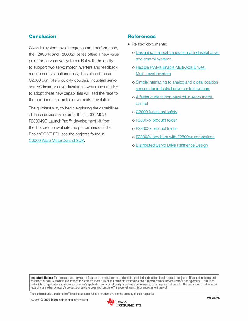
Conclusion
Given its system-level integration and performance,
the F28004x and F28002x series offers a new value
point for servo drive systems. But with the ability
to support two servo motor inverters and feedback
requirements simultaneously, the value of these
C2000 controllers quickly doubles. Industrial servo
and AC inverter drive developers who move quickly
to adopt these new capabilities will lead the race to
the next industrial motor drive market evolution.
The quickest way to begin exploring the capabilities
of these devices is to order the C2000 MCU
F280049C LaunchPad™ development kit from
the TI store. To evaluate the performance of the
DesignDRIVE FCL see the projects found in
C2000 Ware MotorControl SDK.
References
• Related documents:
o Designing the next generation of industrial drive
and control systems
o Flexible PWMs Enable Multi-Axis Drives,
Multi-Level Inverters
o Simple interfacing to analog and digital position
sensors for industrial drive control systems
o A faster current loop pays off in servo motor
control
o C2000 functional safety
o F28004x product folder
o F28002x product folder
o F28002x brochure with F28004x comparison
o Distributed Servo Drive Reference Design
SWAY022AThe platform bar is a trademark of Texas Instruments. All other trademarks are the property of their respective
owners. © 2020 Texas Instruments Incorporated
Important Notice: The products and services of Texas Instruments Incorporated and its subsidiaries described herein are sold subject to TI’s standard terms and conditions of sale. Customers are advised to obtain the most current and complete information about TI products and services before placing orders. TI assumes no liability for applications assistance, customer’s applications or product designs, software performance, or infringement of patents. The publication of information regarding any other company’s products or services does not constitute TI’s approval, warranty or endorsement thereof.

IMPORTANT NOTICE AND DISCLAIMER
TI PROVIDES TECHNICAL AND RELIABILITY DATA (INCLUDING DATASHEETS), DESIGN RESOURCES (INCLUDING REFERENCE DESIGNS), APPLICATION OR OTHER DESIGN ADVICE, WEB TOOLS, SAFETY INFORMATION, AND OTHER RESOURCES “AS IS” AND WITH ALL FAULTS, AND DISCLAIMS ALL WARRANTIES, EXPRESS AND IMPLIED, INCLUDING WITHOUT LIMITATION ANY IMPLIED WARRANTIES OF MERCHANTABILITY, FITNESS FOR A PARTICULAR PURPOSE OR NON-INFRINGEMENT OF THIRD PARTY INTELLECTUAL PROPERTY RIGHTS.These resources are intended for skilled developers designing with TI products. You are solely responsible for (1) selecting the appropriate TI products for your application, (2) designing, validating and testing your application, and (3) ensuring your application meets applicable standards, and any other safety, security, or other requirements. These resources are subject to change without notice. TI grants you permission to use these resources only for development of an application that uses the TI products described in the resource. Other reproduction and display of these resources is prohibited. No license is granted to any other TI intellectual property right or to any third party intellectual property right. TI disclaims responsibility for, and you will fully indemnify TI and its representatives against, any claims, damages, costs, losses, and liabilities arising out of your use of these resources.TI’s products are provided subject to TI’s Terms of Sale (www.ti.com/legal/termsofsale.html) or other applicable terms available either on ti.com or provided in conjunction with such TI products. TI’s provision of these resources does not expand or otherwise alter TI’s applicable warranties or warranty disclaimers for TI products.
Mailing Address: Texas Instruments, Post Office Box 655303, Dallas, Texas 75265Copyright © 2020, Texas Instruments Incorporated