pic anybody? issn 1466-6790 cq-tv 213 · issn 1466-6790 notice to contributors authors are alone...
TRANSCRIPT

ISSN 1466-6790
The leftovers!
CQ
-TV
213
F e b r u a r y2 0 0 6 www.cq-tv.com
PIC anybody?

Page � CQ-TV �13 - February �006 Copyright © by the BATC
BlackBoxCamera™ Company LimitedThe STVKBD unit allows control of the STV5730A’s functionality from a PC keyboard. For full details of the unit’s operation please see the documentation.
This unit features the ability to construct scrolling video text overlays from text typed on each of the units four available screen pages. Each message can be upto 308 characters long. Text, and the scrolling feature, are stored when the unit is switched off and scrolling will restart when power is restored. The unit uses the standard UK keyboard key mapping, see the documentation. There is no facility to change to the keyboard mappings of other countries.
The unit is housed in a smart ABS plastic enclosure with phono connectors for video in / out, a �.1mm DC power socket and a 9V PP3 battery clip. It is designed to be powered from the same power supply as the camera and so the unit does not have a power switch. Keyboard connection is via a 6-pin mini DIN socket for a PS/� keyboard.
►Compatiblewithcolourandmonocompositevideosignals.1Vp-p.PALorNTSC* ►Dimensions110x65x28mmLxWxH ►Powersupply9-12dcviaonboardregulatoror9VPP3backupbattery ►Powerconsumption50mA(withoutkeyboard)
*Bydefaulttheunitwillbesuppliedcompatiblewiththevideostandardofthecountryfromwhichyoumakeyourorder.
If you require further information please contact us: [email protected]
Visit our web site at - www.stv5730a.co.uk
For the person who requires a practical guide on how to light for television and film, without cumbersome reasons arguments, pros and cons, etc. This book provides proven examples of everyday lighting situations that may occur in any television or film studio and outside locations. One does not need to know how a television camera works or how a film camera works, but this knowledge is helpful and some attempt must be made to understand the basic principals.
To understand how the requirements for television and film in terms of the lighting luminaries, power requirements, the light intensities, and most importantly the colour temperature of the light sources, their directional angle and their quality as hard or soft light sources. Recognise the difference between hard shadows and soft shadows.
Letitbesaidthatonedoesneedakeeninterestinthe subject in order to master it.
This ebook is available on CD exclusively from the BATC at a cost of £5 including postage.
Copyright © by the BATC CQ-TV �13 - February �006 Page 3
Edited by Ian Pawson, circuits drawn by Allan Robinson, proofread by Peter Delaney. All rights reserved, all wrongs denied
Copyright © by the BATC and contributors.Legal Niceties (the small print)E&OE.Whilsteverycareistakenintheproductionofthispublication,theeditoraccepts no legal responsibility for the advice, data and opinions expressed. The BATC neither endorses nor is it responsible for the content of advertisements or the activities of those advertisers. No guarantee of accuracy is implied or given for the material herein. The BATC expressly disclaims all liability to any person in respect of anything and in respect of the consequences of anything done or omitted to be done wholly or partly in reliance upon the whole or any part of this magazine.As the regulations for the operation of radio frequency equipment vary in differ-ent countries, readers are advised to check that building or operating any piece of equipment described in CQ-TV will not contravene the rules that apply in their own country.The contents of this publication are covered by international copyright and must not be reproduced without permission, although an exception is made for not-for-profitpublications(only)wishingtoreprintshortextractsorsinglearticlesandthen only if acknowledgment is given to CQ-TV.Apart from any fair dealing for the purposes of published review, private study or research permitted under applicable copyright legislation, no part of this publication may be reproduced, stored in a retrieval system or transmitted in any form or by any means, electronic, mechanical, photocopy, recording or otherwise, without the prior permission of the publisher. All copyrights and trademarks mentioned in this publication are acknowledged and no infringement of the intellectual copyright of others is intended. Printed in Great Britain. ISSN 1466-6790Notice to ContributorsAuthors are alone responsible for the content of their articles, including factual and legal accuracy, and opinions expressed by them may not reflect the editorial stance of the publication. Material submitted to CQ-TV should not infringe the copyright of other writers or bodies. Articles remain the copyright of their authors and follow-ing publication in CQ-TV, they may also appear on the BATC’s web site and CD-ROMs, also in other not-for-profit amateur publications. Contributions are accepted for publication on this basis alone.Printed by Hastings Printing Company Ltd., Dury Lane, St Leonards on Sea, TN38 9BJ, England. Telephone: 01424 720 477.
A Digital Measurement Technique ......................................................................45A progress report on the ATV project for the ISS ...............................................�5ATV Repeater Update – December �005 ............................................................36BATC Publications ..............................................................................................11Captioncompetition ..............................................................................................51Caption competition �1� result ............................................................................�6Chairman’s Column ...............................................................................................5Circuit Notebook No. 88 .....................................................................................�7Committee Contacts ...............................................................................................4Contents .................................................................................................................3CQ-TV Commercial Advertising Rates ...............................................................50Deadlines ..............................................................................................................50Feelings ................................................................................................................48Index of Advertisers .............................................................................................50LenstoLens-Part1 .............................................................................................31Members Services ................................................................................................11Project Development with PICs ..........................................................................1�Subscription Rates ...............................................................................................37The Alford Slot ....................................................................................................41The Care and Feeding of Vintage Broadcast Cameras ........................................17Turning Back the Pages .......................................................................................38Tutorial on Video and Audio Switching ................................................................6Veteran Marconi ...................................................................................................49You’re Been Served .............................................................................................30
Contents
CQ
-TV
213

Page 4 CQ-TV �13 - February �006 Copyright © by the BATC
President: Mike Cox, CEng., FIEEE-mail: [email protected]
Chairman: Trevor Brown, G8CJSClub affairs, Videotape library, and Technical queries, especially relating to handbook projects. 14 Stairfoot Close, Adel, Leeds,LS168JR.Tel:01132670115.E-mail: [email protected]
General Secretary: Paul Marshall, G8MJWGeneralclubcorrespondenceandbusiness.Libraryqueriesrelatingtotheborrowingordonationofwrittenmaterial.FernHouse,ChurchRoad,Harby,Notts.,NG237ED.Tel:[email protected]
Hon. Treasurer: Brian Summers, G8GQSEnquiries regarding club finances, Donations, and constitutional enquiries. 9 Prior Croft Close, Camberley, Surrey, GU15 1DE. Tel: 01�76 677879, Mobile077 40�9 1191, Email: [email protected]
MembershipAnything to do with membership, including new applications, queries about new and existing membership, non-receipt of CQ-TV, subscriptions, membership records etc. Pat Hellen,TheVilla,PlasPanteidal,Aberdyfi,Gwynedd,LL350RF,UK. Telephone 01654 76770�. E-mail: [email protected]
Club Liaison: - And anything of a political nature, co-ordination of ATV repeater licences. Graham Shirville, G3VZV, TheHillFarm,Potsgrove,MiltonKeynes,Bucks.,MK179HF.Tel:[email protected]
Contests: - Richard Parkes, G7MFO, 7 Main Street, Preston, Hull, HU12 8UB. Tel: 01482 898559. Email:[email protected]
CQ-TV Magazine: Editor Ian PawsonAnythingforpublicationinCQ-TV,Articles,Reviewitems,Letterstotheeditor,andothermaterialexceptasbelow.14LilacAvenue,Leicester,LE51FN,England.Tel:01162769425,Email:[email protected]
Photographs for the CQ-TV covers: - Please send any photographs by post, electronic images by email, to the editor at the above addresses.
TV on the Air: - Graham Hankins G8EMX,17CottesbrookRoad,AcocksGreen,Birmingham,B276LE.Tel:0121706 7384
Satellite TV News: - Paul Holland G3TZO,Chatterton,ChapelLane,Threapwood,Nr.Malpas,Cheshire,SY147AX.Tel: 01948 7704�9, Email: [email protected]
CQ-TV Advertising Manager: - Trevor Brown,14StairfootClose,Adel,Leeds,LS168JR.Tel:01132670115.Email:[email protected] Members adverts for inclusion in CQ-TV should be sent directly to the editor and the above address, either by post or e-mail.
CQ-TV Awards: - Bob Webb G8VBA, 78 Station Road, Rolleston on Dove, Burton on Trent, Staffs., DE13 9AB. Tel: 01�83 81458�
ExhibitionsGraham Hankins G8EMX,17CottesbrookRoad,AcocksGreen,Birmingham,B276LE.Tel:01217067384Email:[email protected]
Club SalesMembers Services: - PCB’s, components, camera tubes, accessories, etc. (NOTPUBLICATIONS).Peter Delaney, G8KZG,6EastViewClose,Wargrave,Berkshire,RG108BJ.Tel:01189403121.Email:[email protected]
Publications: - Handbooks, Back copies CQ-TV, and anything related to the supply of BATC publications. Paul Marshall,FernHouse,ChurchRoad,Harby,Notts.,NG237ED,England.E-mail: [email protected]
CQ-TV and BATC web mastersAnything to do with the CQ-TV web site Email: [email protected] or for the BATCs web site. E-mail: [email protected]
Committee Contacts
Copyright © by the BATC CQ-TV �13 - February �006 Page 5
Chairman’s Column
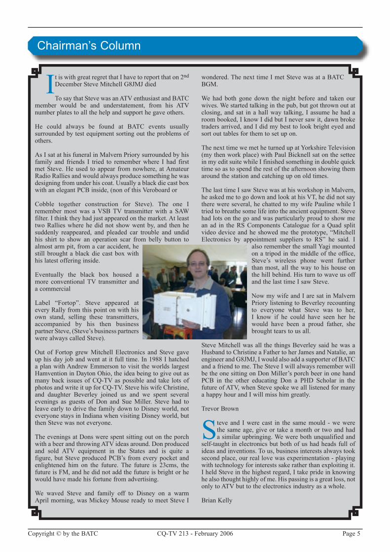
It is with great regret that I have to report that on �nd DecemberSteveMitchellG8JMJdied
To say that Steve was an ATV enthusiast and BATC member would be and understatement, from his ATV number plates to all the help and support he gave others.
He could always be found at BATC events usuallysurrounded by test equipment sorting out the problems of others.
As I sat at his funeral in Malvern Priory surrounded by his family and friends I tried to remember where I had first metSteve.Heused toappear fromnowhere, atAmateurRadio Rallies and would always produce something he was designing from under his coat. Usually a black die cast box withanelegantPCBinside,(nonofthisVeroboardor
Cobble together construction for Steve). The one Iremembermostwas aVSBTV transmitterwith a SAWfilter. I think they had just appeared on the market. At least two Rallies where he did not show went by, and then he suddenly reappeared, and pleaded car trouble and undid his shirt to show an operation scar from belly button to almost arm pit, from a car accident, he still brought a black die cast box with his latest offering inside.
Eventually the black box housed a more conventional TV transmitter and a commercial
Label “Fortop”. Steve appeared atevery Rally from this point on with his own stand, selling these transmitters, accompanied by his then business partnerSteve,(Steve’sbusinesspartnerswerealwayscalledSteve).
Out of Fortop grew Mitchell Electronics and Steve gave up his day job and went at it full time. In 1988 I hatched a plan with Andrew Emmerson to visit the worlds largest HamventioninDaytonOhio,theideabeingtogiveoutasmany back issues of CQ-TV as possible and take lots of photos and write it up for CQ-TV. Steve his wife Christine, and daughter Beverley joined us and we spent several evenings as guests of Don and Sue Miller. Steve had to leave early to drive the family down to Disney world, not everyone stays in Indiana when visiting Disney world, but then Steve was not everyone.
The evenings at Dons were spent sitting out on the porch with a beer and throwing ATV ideas around. Don produced and sold ATV equipment in the States and is quite a figure, but Steve produced PCB’s from every pocket and enlightened him on the future. The future is �3cms, the future is FM, and he did not add the future is bright or he would have made his fortune from advertising.
We waved Steve and family off to Disney on a warmApril morning, was Mickey Mouse ready to meet Steve I
wondered. The next time I met Steve was at a BATC BGM.
We had both gone down the night before and taken ourwives.Westartedtalkinginthepub,butgotthrownoutatclosing, and sat in a hall way talking, I assume he had a room booked, I know I did but I never saw it, dawn broke traders arrived, and I did my best to look bright eyed and sort out tables for them to set up on.
The next time we met he turned up at Yorkshire Television (mythenworkplace)withPaulBicknellsatonthesetteein my edit suite while I finished something in double quick time so as to spend the rest of the afternoon showing them around the station and catching up on old times.
The last time I saw Steve was at his workshop in Malvern, he asked me to go down and look at his VT, he did not say there were several, he chatted to my wife Pauline while I tried to breathe some life into the ancient equipment. Steve had lots on the go and was particularly proud to show me an ad in the RS Components Catalogue for a Quad split videodeviceandheshowedme theprototype,“MitchellElectronics by appointment suppliers to RS” he said. I
also remember the small Yagi mounted on a tripod in the middle of the office, Steve’s wireless phone went further than most, all the way to his house on thehillbehind.Histurntowaveusoffand the last time I saw Steve.
Now my wife and I are sat in Malvern Priory listening to Beverley recounting to everyone what Steve was to her, I know if he could have seen her he would have been a proud father, she brought tears to us all.
Steve Mitchell was all the things Beverley said he was a HusbandtoChristineaFathertoherJamesandNatalie,anengineerandG8JMJ,IwouldalsoaddasupporterofBATCand a friend to me. The Steve I will always remember will be the one sitting on Don Miller’s porch beer in one hand PCB in the other educating Don a PHD Scholar in thefuture of ATV, when Steve spoke we all listened for many a happy hour and I will miss him greatly.
Trevor Brown
Steve and I were cast in the same mould - we were the same age, give or take a month or two and had asimilarupbringing.Wewerebothunqualifiedand
self-taught in electronics but both of us had heads full of ideas and inventions. To us, business interests always took second place, our real love was experimentation - playing with technology for interests sake rather than exploiting it. I held Steve in the highest regard, I take pride in knowing healsothoughthighlyofme.Hispassingisagreatloss,notonly to ATV but to the electronics industry as a whole.
Brian Kelly

Page 6 CQ-TV �13 - February �006 Copyright © by the BATC
By Mike Cox
By the time you have read this, you should have a better understanding of the techniques
used in switching video and audio in a clean manner.
It will deal with the basic concept of a crosspoint, expand several crosspoints into a switch matrix and look at the input and output constraints and the type of signal being switched. To conclude, we will look at crosspoint and matrix control.
The CrosspointThe simplest crosspoint is a switch. Many of us have used double-throw toggle switches as a simple way of selecting one video from two at say a monitor input. Another example is the push button switch, often used in so-called “bang boxes” to selectvideo or audio, or sometimes both. Howeversuchdeviceshavelimitations,particularly when more than one output of a signal is required. We need toconsider other options.
We can get round the output feedproblembyfollowingthecrosspoint(s)with a buffer amplifier. This will allow several isolated feeds to be taken. [Fig. 1]
An improvement on the direct switch is the relay. This allows control from a distance.
However all these mechanicalcrosspoints suffer from speed of operation limitations.
For many applications, the switching action needs to be completed in tens of nanoseconds. This dictates the use of semiconductors. These in turn can be divided into the passive semiconductor crosspoint such as that using diodes [Fig.�A] or FETs [Fig.�B], and the active kind using transistors, where they are used as impedance transformers. [Fig.�C shows an active crosspoint. Note theLEDin thecollectorofQn1.This indicates that crosspoint is on.] It is worth noting that for very simple applications, CMOS switches such as CD4051 or 74HC4051 can be very
useful, but do not expect wonderful crosstalkperformanceatHF.
Most of these considerations apply whether the signal being switched is analog or digital.
Howeverwithadigitalsignalwearenotvery concerned about linearity, whereas with analog, it is our main concern. With analog, our other concerns arefrequency response, and in the case of more than two inputs, crosstalk between them.
Mechanical switches have very low series resistance, and capacitive loading at the output will have little effect at video frequencies. If we use diodes or FETs, the series resistance will be in the region of tens or hundreds of ohms, and the –3dB point could well be in the upper video band. Further, you cannot possibly use such crosspoints directly into a 75-ohm load. A buffer amplifier has to be used. The transistor crosspoint has some advantages in that two emitter followers in tandem offer a high input impedance, and a low output impedance together with practically zero dc offset. Obviously a mechanical switch should not have any dc offset.
Most of these remarks apply equally to audio switching, except that the levels in audio are higher than video. Video is normally 1 volt peak to peak, whereas audio, while nominally 0 dBm [0.778 V rms, �.� V pk-pk], can go up to +�0 dBm. This is why audio switchers and buffer amplifiers need +/- 15-volt supply rails, while modern video switchers and
Tutorial on Video and Audio Switching

Copyright © by the BATC CQ-TV �13 - February �006 Page 7
amplifiers can work happily on +/- 5-volt rails. A technique that is sometimes used is to attenuate the audio input by 10 dB or so, and apply 10 dB of gain in the output buffer. This lowers the signal to noise ratio, and may not always be acceptable.Whenswitchingaudio,caremust be taken with any dc at switch inputs, or switching clicks or worse will result. As most audio circuits are ac coupled, this should not be too big a problem. It is perhaps why FET switches are popular for audio as they behave as a resistor that has either very high or very low value.
The MatrixLetusconsideraswitcherwith5inputsand 5 outputs, such as might form the heart of a vision mixer. [Fig. 3] There will be stray capacitance around the matrix, at the in and out of each crosspoint, and on the common rail feeding each output stage, called a busbar.
Any given on crosspoint [assuming only one input can be selected at a time for each output] will be feeding the output capacitance of all the other 4 crosspoints, and the input capacity of the output amplifier plus the capacitance of the busbar. In addition to this consideration, the feedthrough capacitance of each crosspoint into the output impedance of the on crosspoint will cause high frequency crosstalk, and has to be considered.
If we look in some more detail at the effective circuits of the on and off crosspoint [Fig. 4], the parasitic components of most concern are the Rseries ON, the Cseries OFF and the Cshunt. The Rseries and the Cshunt constitute a low pass filter, and we must bear in mind that Cshunt is made up of the busbar capacitance and the off capacitance of the other crosspoints. Rseries will be several tens of ohms with diode or FET crosspoints.
The –3dB point will be at the frequency
where Xcshunt = Rseries, and Xc=½πfC
Crosstalk will be dependent on Cseries, but with the 3 - s w i t c h configuration, this is reduced to a minimum.
There are other considerations in a matrix; if an input is selected to all outputs, the capacitative loading on the busbar may change and cause a change in frequency response. In the days of the IBA Code of Practice, response had to be within 0.1 dB at 4.43 MHz under all conditions and routesthrough a mixer or switcher.
Another problem which can arise, particularly with active crosspoints such as the one shown in Fig. �C, is that of axis shift. This effect is caused by partial rectification ofHF componentsin the video signal giving a dc shift to that part of the waveform. For example,
if the signal is a multiburst or line sweep, it may show an exaggerated HFresponseduetothiseffect.Equallythe subcarrier envelope of colour bars will be moved up and make alignment difficult. With a number of possibleroutes through a mixer, alignment can be almost impossible if one is to satisfy the IBA Code requirements. I write from bitter past experience. The killer is an emitter follower sitting in inadequate current trying to drive a capacitative load. This is made up of the off C shunt of all the other crosspoints on the busbar plus strays. [Fig. 5, Fig. 5B]
Some of you may remember from valve days the infinite impedance detector, which was a cathode follower feeding a fairly large C and R load. Under certain conditions, that is what the emitter follower is doing. The problem was so bad in some complex mixers that a corrector was made up that added the opposite error so as to cancel the original.
ApplicationWhat is the matrix to be used for? Ifit is as a routing switch [US parlance –a“rowter”],aslongasthedistortion

Page 8 CQ-TV �13 - February �006 Copyright © by the BATC
and frequency response specification is met, we need not consider things like dc [within reason]. If it is part of a vision or presentation mixer where “live” switching is taking place, weneed to consider this carefully.
Video sources have differing dc sits at their outputs. Some have the black level set carefully at 0 volts where it sits whatever the video Average Picture Level [APL]. Others are oftenac coupled, where the black level dc changes withAPL, and where the dcmaybeupbyavoltorso.Wearenotusually in a position to do anything about this. Switching between two video signals with different black level dc will cause downstream sync separators to give a break in the sync stream at
the vertical interval, causing a frame roll. The design of the input buffer amplifier for the matrix can put this right by incorporating a dc restorer. In its simplest form, this will use a diode [or transistor emitter-base junction] as a sync tip restorer [Fig. 6], or an individual sync separator driving a back porch clamp. Neither of these will work very well with a non-composite signal such as RGB. An external reference signal must be used to produce clamp pulses in such a case.
Luckily for the designer, there are anumber of integrated circuit op amps that meet the needs of input and output buffers in a matrix. Some have disable pins that can help in the design of complex switchers, and most can drive
more than 1 75-ohm load. Elantec and Gennum make dc-restored buffers that work well. Gennum also make active crosspoints in singles or groups of 4 in a 14 pin package, and Maxim make a range of switching ICs up to complete matrices, some including 75-ohm output drivers. [CQ-TV 195] [Fig. 7, Fig. 8]
The last consideration in a mixer matrix istiming.ForaPALmixer,anysourceto the mixer output should have a timing accuracy to 1 or � degrees of subcarrier phase. This requirement will dictate the physical layout of the matrix. Path lengths need to be equal for each source to the busbars. If this is not done it may be impossible to time the mixer up.

Copyright © by the BATC CQ-TV �13 - February �006 Page 9
ControlCrosspoints need to be controlled so that when a source button is pressed, it is latched and the corresponding crosspoint turned on. Further, in a mixer, the time at which the crosspoint turns on may need to be on a defined line in the vertical interval. This is not essential in a routing switcher, as signals may be non-synchronous, and downstream equipment can take care of any picture disturbance.
The complexity of such circuitry will depend on the crosspoint design.
Individual crosspoints need a wire per crosspoint, whereas grouped crosspoints such as the Gennum, Maxim and the CMOS 74HC405X series have binarycontrol, which saves wires.
The first switchers that I was involved with used the active crosspoint [Fig.�C], with an SCR latch per crosspoint. HowevertherearenumerouslogicICsavailable that help decode binary to wire-a-function and conversely. ICs such as the 74HC4514 [4 wire to 16decoder] spring to mind.
The ICs made by Maxim, and the SDI 8 x 8 IC made by Gennum [GS9533, see CQ-TV�07] use a source and destination type of control. In the case of an 8 x 8 switcher like the GS9533, there are 3 destination lines, 3 source lines, Config and Load lines. Thematrix is set up by selecting a source, selecting a destination and pressing a Load button.An article in CQ-TV208showed how to add 7 segment read-outs to the panel.
If the control panel is to be some way from the matrix, some form of serial control is advisable using RS4�� as this will simplify cabling. Use of UARTs [see CQ-TV �0�/�03] at each end makes implementation of RS4�� relatively straightforward. Or you might persuade Brian Kelly to design a PIC circuit for you!
For more complex switchers, inputs and outputs can be increased by using many ICs with their corresponding enable pins. Analog Component Switchers need to have 3 layers controlled in parallel. [CQ-TV195] It is possible to have a 3-layer switch matrix on one card, which keeps all the channels in the same thermal environment. Successful 10 x � x 3-layer cards have been produced on a ��0 x �33 Eurocard.
With these complex switchers, greatcare has to be taken with signal return currents so that they return down the coax outer directly to their output amplifier. This is why you sometimes see ferrite cores on coaxial cables at the connector end. This puts a high impedance to common mode signals on the cable. Any common path with other outputs can result in degraded crosstalk performance. Power supply routing and decoupling is also important. Just likeRF really, and you know all about that anyway!
Conclusions In this short piece, we have looked at the essentials of crosspoints, at the necessity of dc maintenance in some but not all cases, at considerations in design of a matrix, and some thoughts on control.
Reference has been made to earlier CQ-TV articles; buying the CQ-TV DVD means you will have all these articles and more in printable form to refer to; and the pictures will be in colour! The best £5 you will ever spend.
Haveago!

Page 10 CQ-TV �13 - February �006 Copyright © by the BATC

Copyright © by the BATC CQ-TV �13 - February �006 Page 11
BATC Publications
Publication Each Qty Total
AnIntroductionToAmateurTelevision(225gm) . . . . . . . . . . . . . . . . . . . . . . . . . . . . . . . . . . . . . £5.00 . . . . .......... . . . ...........The latest handbook full of detailed information on how to set up your ATV station, plus lots of new video and RF construction projects.TheAmateurTVCompendium(155gm) . . . . . . . . . . . . . . . . . . . . . . . . . . . . . . . . . . . . . . . . . . . £3.50 . . . . .......... . . . ............The BATC handbook featuring construction articles on video units, �4cm and 3cm ATV, a Digital Frame Store, and much more.TheBestofCQ-TV(150gm). . . . . . . . . . . . . . . . . . . . . . . . . . . . . . . . . . . . . . . . . . . . . . . . . . . . . £3.50 . . . . .......... . . . ............A compilation of the best construction articles from CQ-TV’s 133 to 146CQ-TV Back Issues: . . . . . . . . . . . . . . . . . . . . . . . . . . . . . . . . . . . . . . . . . . . . . . . . . . . . . . . . . . . £1.50 . . . . .......... . . . ............The following issues are still available. Please circle those required: 14�, 143, 144, 147, 150, 153, 154, 156, 158 159, 16�, 163, 164, 166, 167, 168, 169, 170, 171, 173, 174, 175,176, 177,178, 179, 180, 181. 18�, 183, 184, 185, 186, 187, 188,189, 190, 191, 19�, 193, 194, 195, 196, 197, 198, 199, �00, �01, �0�, �03, �04, �05, �06, �07, �08, �09Special Offer: Any four of the above issues . . . . . . . . . . . . . . . . . . . . . . . . . . . . . . . . . . . . . . . . . £5.00 . . . . .......... . . . ............�10, �11, �1�, �13 . . . . . . . . . . . . . . . . . . . . . . . . . . . . . . . . . . . . . . . . . . . . . . . . . . . . . . . . . . . . . £3.75 . . . . .......... . . . ............The BATC DVD . . . . . . . . . . . . . . . . . . . . . . . . . . . . . . . . . . . . . . . . . . . . . . . . . . . . . . . . . . . . . . £5.00 . . . . .......... . . . ............LightingforTelevisionandFilm(ebookonCD) . . . . . . . . . . . . . . . . . . . . . . . . . . . . . . . . . . . . . £5.00 . . . . .......... . . . ............
All prices in UK pounds (£) Each P&P Qty Total
Camera Tubes, Scan Coils, Bases & Lens Mounts3 One inche Vidicon base £1.�0 £0.30 .......... ..........4 �/3 inch Vidicon base £0.80 £0.30 .......... ..........
Video and I2C Circuit Boards/Components7 Sync pulse generator PCB £14.00 £0.43 .......... ..........40 I�C CPU PCB £10.00 £0.43 .......... ..........41 I�C VDU PCB £10.00 £0.43 .......... ..........43 SAA5�31 Genlock IC £8.80 £0.30 .......... ..........44 SAA5�43PE Teletext IC £14.70 £0.30 .......... ..........45 PCF8583 Clock IC £7.00 £0.30 .......... ..........39 LM1881NSyncseparatorIC £3.50 £0.30 .......... ..........81 I�C �7�56 EPROM £9.70 £0.30 .......... ..........38 PCF8574P Input expander IC £4.70 £0.30 .......... ..........10 I�C Relay PCB £6.50 £0.43 .......... .......... 9 PCF8574A Input expander IC £4.70 £0.43 ......... ..........
RX, TX and SSTV PCB’s and General Components47 70cm up converter PCB £13.50 £0.43 .......... ..........50 108.875MHzcrystal £8.20 £0.30 .......... ..........68 4.433618MHzcrystal £3.25 £0.30 .......... ..........69 5.0MHzcrystal £3.25 £0.30 .......... ..........86 �4cm solid-state amplifier PCB £10.50 £0.43 …….. ……..Stationery & Station Accessories73 BATC blue diamond clutch pin badge £1.75 £0.30 .......... ..........74 BATC cloth badge £4.00 £0.30 .......... ..........75 BATCequipmentlabel(6) £0.25 £0.30 .......... ..........76 BATC square windscreen sticker £0.10 £0.30 .......... ..........78 BATC test card £0.50 £0.43 .......... ..........79 BATC reporting chart £0.10 £0.43 .......... .......... Total goods and postage - amount enclosed £..……........
PLEASE MAKE CHEQUES PAYABLE TO ‘BATC’.
Members Services
All goods on this page can be ordered, with a credit card, via our online shop - www.batc.org.uk

Page 1� CQ-TV �13 - February �006 Copyright © by the BATC
By Brian Kelly. GW6BWX
The family of PIC microcontrollers is now huge, there are several hundred different types although
still all based around the same core functions. The different families are to cater for just about every users needs, some have just six pins while others have as many as 68, allowing them to control the simplest of circuits to highly complex ones. A wide variety of on-board interfaces are also available, ranging from single ‘on/off’ pins to Ethernet ports and amazingly, despite some running at 20MHz or moreclock speeds, they draw barely a few milliamps of power. The smallest 10F series devices draw less than half a milliamp while running and only nano-ampsinsleepmode.Withsuchabroadchoice of built in facilities it is unlikely you would find a family member that doesn’t have everything you need for any controller application.
Most of the newer PIC devices use FLASHmemory.Thisisnotanopticalphenomenon! it is a kind of memory that retains it’s program or data even when power is removed from it. In fact most devices have a predicted memory life of 40 years, even after 100,000 reprogramming cycles. The fact that the chip can be reprogrammed is extremely useful, the chips effectively never become redundant, if the equipment using it becomes obsolete or is no longer needed, the chip can be erased and reprogrammed for an entirely new purpose. During program development it makes life ever so easy, if you find a bug or want to try something new you just wipe it clean and start again. Erasing and reprogramming takes just a few seconds and in many cases can be done without removing the chip from its circuit board.
Many of the smaller PIC devices have internal clock oscillators so that none of the limited number of pins have to be dedicated to setting their operating frequency. To make sure the on-board oscillator is ‘tuned’ to the right frequency, they are calibrated during manufacture although it is possible to recalibrate them later if ever needed. Most devices with internal oscillators can still be externally driven or connected to a crystal for applications needing non-standard frequencies or extreme stability.
Now that all the components that used to be necessary around the device are built into it, you can for example make a Morse callsign generator in just two components – and one of them is just a resistor to lower the volume!
The mere thought of writing a program scares most people away from PIC devices. The fear of programming is unfounded; they are extremely easy to
use. The most complicated, although most versatile method of programming is to write in assembly language. In this language, you write individual instructions for the processor to run. To be fair, there are only 35 instructions to learn and of these, probably half are rarely used. Because you have total control of the program flow, you can write very efficient and fast running programs. These days there are many
Project Development with PICs
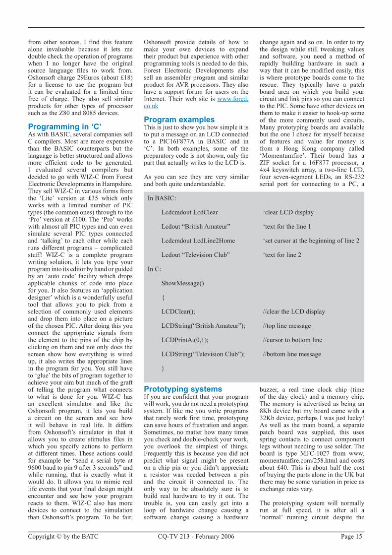
The Quasar Electronics 3150 chip programmer. It can program chips smaller than the 40-pins of the ZIF socket. The connections at the top are for power and USB. The pins at the bottom can be used to program chips which are already mounted on a PCB so they don’t have to be removed and placed in the ZIF socket. This is called ‘in
circuit serial programming’.

Copyright © by the BATC CQ-TV �13 - February �006 Page 13
tools available that make it much easier to code more complicated tasks by using what are called ‘high level’ languages. These are computer programs that accept a more humanly readable set of instructions and convert them into one or more assembler instructions.Whenyou use high level languages, you never have to see the underlying codes at all, everything at processor level is still there but hidden from you. Sadly, high-level languages seldom produce assembler code as efficiently as can be achieved by writing it by hand but the simplicity of the code far outweighs this disadvantage in all but the most critical applications.
If you want to ‘play’ with PIC devices you will need two tools. One is the electronic circuit that actually takes the program from your computer and stores it into the silicon memory on the chip itself. The other is a tool to write the program in the first place. Not essential, but useful is a prototyping system that allows you to temporarily build a circuit around your programmed chip. This could be just to test a fragment of program or to verify a design before building it in more finalised form. The
next sections look at what tools are available in more detail.
Programming the chipThere are many designs on the Internet for DIY PIC programmers and also many commercially marketed units. Most of these can handle several families of PIC chips, the more advanced ones can handle them all. For the average experimenter, one that can handle the 16F84A, 16F6�8A and 16F877A will suffice. Beware of ones that can’t manage devices with an ‘A’ at the end of their part numbers as the programming methods used with these later devices is different to their predecessors without the ‘A’. The simplest designs on the Internet use just a few common components and connect to the computer printer port. Some are self-powering but most also need 1�V or more from a power supply or mains adapter. After looking at many commercially available units I chose one of the ones from Quasar Electronics for myself. Quasar are based in Bishops Stortford in the UK. They market several versions of their programmers, some for parallel(printer)portconnection,somefor serial port connection and the one I
chose which hooks up to a USB port. Whenchoosingaprogrammer,Iadvisegetting or building one with a ZIF socket for the chip being programmed. ZIF stands for Zero Insertion Force, the chip drops into the socket and is then locked in place by lowering a small lever. Raising the lever releases the chip. Conventional sockets where you push the chip against springy side contacts are cheaper but quickly wear out. I have one ZIF socket that still works after more than 10 years of hard labour! The USB programmer costs £39.95 with a conventional socket or £54.95 with a ZIF socket. The non-USB versions are cheaper. It is ready built and has support software which is periodically updated on the Quasar web site: www.quasarelectronics.com
Writing programsAs mentioned earlier, there is a choice of languages to write programs in. For the smaller devices with little memory, it is probably easiest to write in assembly language. High-levellanguages tend to add extra instructions that eat into valuable memory space. If more than about 1Kb of memory is available, and most PICs have at least
Oshonsoft’s simulator with the program, LCD, LED and stack windows open. These are just some of the windows you can open to look at the inner workings of the program. The pink dots in the program window
are a map of individual bits turned on in the processors internal registers.

Page 14 CQ-TV �13 - February �006 Copyright © by the BATC
that much, you should consider high-level languages for their simplicity of use. Generally, the word ‘assembler’ is used to describe software that converts individual human readable instructions to PIC machine code on a one-to-one basis and the word ‘compiler’ describes software that converts high-level language instructions to possibly hundreds of PIC machine codes.
If assembly language is your choice, you can do no better than use the PIC manufacturers own program writing package called MPLAB. The currentversion is 7.�� but new releases come out every few months to add support for new chip types. MPLAB is a bigprogram, weighing in at about 80Mb when installed but it does handle all the PIC varieties and it includes an editor to write the program and a powerful simulator that lets you ‘run’ the program from within MPLAB to make sure itbehaves as expected before committing it to a real chip. You can download MPLAB free of charge from www.microchip.com.
If you prefer the convenience of high-level languages, there are two common ones available; they are BASIC and ‘C’. BASIC is a simple language, originally written for beginners back in the 1970s but now adapted to work with PICs as well as PCs and larger computer systems. The ‘C’ language is a little more complicated to learn but is far more powerful and lends itself to being more ‘convertible’ to assembler instructions. Both languages introduce pre-built functions that are not normally present if you work directly in assembly language. These pre-built functions are a collection of assembly instructions coupled to a method of retrieving and passing back data. You pass data to the function and get data back from it, the function doing something useful with it in the middle. For example, to illuminate the digit 5 on a seven-segment display connected to the PIC in assembly language you would have to set the PIC pins connected to the appropriate LED segments to a highvoltage and the PIC pin joined to the LED common pin to a low voltage.In a high-level language this might be written simply as “SetLED(5)”. Theoutcome is the same but the high-level code is easier to write, understand and if necessary, edit later. Another strength of high-level languages is that you can make your own functions either from assembler instructions or by combining other functions together. Quickly, you stop thinking of making pins of the chip go high or low and start thinking in terms
of what your program is intended to do. If it is a clock telling the time of day for example, you are more interested in knowing if midnight has been reached than the dozens of numbers in the PICs working registers. High-level codinggives you that degree of isolation from the inner workings of the chip.
Programming in BASICSeveral companies market PIC BASIC compilers but after looking at all of them, one stood out from the crowd for it’s simplicity of use and it’s low price. WrittenbyOshonsoft it iscalled“PICSimulatorIDE”andcanbedownloadedfrom www.oshonsoft.com. The ‘IDE’ part of its name stands for ‘Integrated Development Environment’, meaning you can do everything within the program to write, debug, simulate and test your work. Although this program doesn’t have an operating manual in the normal sense, it does give examples of how to use each of it’s commands and the graphical layout of the various display windows makes it very easy
to understand. When a program hasbeen written, it can be tested using a selection of commonly attached devices suchasLCDdisplays,LEDdisplaysanoscilloscope and a waveform generator. All of these devices appear in their own windows on the computer screen and have ‘setup’ options to allow you to connect them to whatever pin you want on the PIC being simulated. When the simulation is run, the mainprogram window shows the sequence of instructions being run and the contents of all the registers inside the chip, windows showing the attached devices update as the PIC sends signals to them. You can run the program at different speeds so you can see what’s happening in slow motion and you can ‘single step’ your program one instruction at a time to see what effect the instruction is having. I even loaded programs written in an entirely different language into PIC Simulator IDE and it correctly emulated their operation. This is one of a very few programs that can read, reverse engineer and run programs
One corner of WIZ-C’s simulation screen. The image is a representation of the pins of the 16F877 being simulated. The colours show whether the pin is an input or an output and the logic level on
it. The numbers in the window on the left are the contents of some of the processors registers. Clicking on the oval buttons allows different
selections of data to be shown.
Copyright © by the BATC CQ-TV �13 - February �006 Page 15
from other sources. I find this feature alone invaluable because it lets me double check the operation of programs when I no longer have the original source language files to work from. Oshonsoftcharge29Euros(about£18)for a license to use the program but it can be evaluated for a limited time free of charge. They also sell similar products for other types of processor such as the Z80 and 8085 devices.
Programming in ‘C’As with BASIC, several companies sell C compilers. Most are more expensive than the BASIC counterparts but the language is better structured and allows more efficient code to be generated. I evaluated several compilers but decidedtogowithWIZ-CfromForestElectronicDevelopmentsinHampshire.TheysellWIZ-Cinvariousformsfromthe ‘Lite’ version at £35 which onlyworks with a limited number of PIC types(thecommonones)throughtothe‘Pro’ version at £100. The ‘Pro’ works with almost all PIC types and can even simulate several PIC types connected and ‘talking’ to each other while each runs different programs – complicated stuff! WIZ-C is a complete programwriting solution, it lets you type your program into its editor by hand or guided by an ‘auto code’ facility which drops applicable chunks of code into place for you. It also features an ‘application designer’ which is a wonderfully useful tool that allows you to pick from a selection of commonly used elements and drop them into place on a picture of the chosen PIC. After doing this you connect the appropriate signals from the element to the pins of the chip by clicking on them and not only does the screen show how everything is wired up, it also writes the appropriate lines in the program for you. You still have to ‘glue’ the bits of program together to achieve your aim but much of the graft of telling the program what connects to what is done for you. WIZ-C hasan excellent simulator and like the Oshonsoft program, it lets you build a circuit on the screen and see how it will behave in real life. It differs from Oshonsoft’s simulator in that it allows you to create stimulus files in which you specify actions to perform at different times. These actions could for example be “send a serial byte at9600baudtopin9after3seconds”andwhile running, that is exactly what it would do. It allows you to mimic real life events that your final design might encounter and see how your program reacts to them.WIZ-C also has moredevices to connect to the simulation than Oshonsoft’s program. To be fair,
Oshonsoft provide details of how to make your own devices to expand their product but experience with other programming tools is needed to do this. Forest Electronic Developments also sell an assembler program and similar product for AVR processors. They also have a support forum for users on the Internet. Their web site is www.fored.co.uk
Program examplesThis is just to show you how simple it is toputamessageonanLCDconnectedto a PIC16F877A in BASIC and in ‘C’. In both examples, some of the preparatory code is not shown, only the partthatactuallywritestotheLCDis.
As you can see they are very similar and both quite understandable.
Prototyping systemsIf you are confident that your program will work, you do not need a prototyping system. If like me you write programs that rarely work first time, prototyping can save hours of frustration and anger. Sometimes, no matter how many times you check and double-check your work, you overlook the simplest of things. Frequently this is because you did not predict what signal might be present on a chip pin or you didn’t appreciate a resistor was needed between a pin and the circuit it connected to. The only way to be absolutely sure is to build real hardware to try it out. The trouble is, you can easily get into a loop of hardware change causing a software change causing a hardware
change again and so on. In order to try the design while still tweaking values and software, you need a method of rapidly building hardware in such a way that it can be modified easily, this is where prototype boards come to the rescue. They typically have a patch board area on which you build your circuit and link pins so you can connect to the PIC. Some have other devices on them to make it easier to hook-up some of the more commonly used circuits. Many prototyping boards are available but the one I chose for myself because of features and value for money is from a Hong Kong company called‘Momentumfire’. Their board has a ZIF socket for a 16F877 processor, a 4x4 keyswitch array, a two-line LCD,four seven-segment LEDs, an RS-232serial port for connecting to a PC, a
buzzer, a real time clock chip (timeof the day clock) and amemory chip.The memory is advertised as being an 8Kb device but my board came with a 3�Kb device, perhaps I was just lucky! As well as the main board, a separate patch board was supplied, this uses spring contacts to connect component legs without needing to use solder. The board is type MFC-10�7 from www.momentumfire.com/�58.html and costs about £40. This is about half the cost of buying the parts alone in the UK but there may be some variation in price as exchange rates vary.
The prototyping system will normally run at full speed, it is after all a ‘normal’ running circuit despite the
In BASIC:
LcdcmdoutLcdClear ‘clearLCDdisplay
Lcdout“BritishAmateur” ‘textfortheline1
LcdcmdoutLcdLine2Home ‘setcursoratthebeginningofline2
Lcdout“TelevisionClub” ‘textforline2
In C:
ShowMessage()
{
LCDClear(); //cleartheLCDdisplay
LCDString(“BritishAmateur”); //toplinemessage
LCDPrintAt(0,1); //cursortobottomline
LCDString(“TelevisionClub”); //bottomlinemessage
}
Page 16 CQ-TV �13 - February �006 Copyright © by the BATC
temporary construction method. Beware though that even on the fastest PCs, a simulation will run much slower thanrealtime.WIZ-Cisactuallyquitefast at simulating a real environment; Oshonsoft’s simulator is considerably slower. They do however, agree exactly on functionality and on their assessment
of execution times if real time could be achieved. Both programs accept code written in assembly language as well as their high-level counterparts.
You have seen here just a small sample of tools available to PIC developers. I use all the programs and the prototype
board described here. The programs each have their strengths and weaknesses but together they make a potent collection of programming tools. I hope I inspire you to try your hand at using these versatile devices.
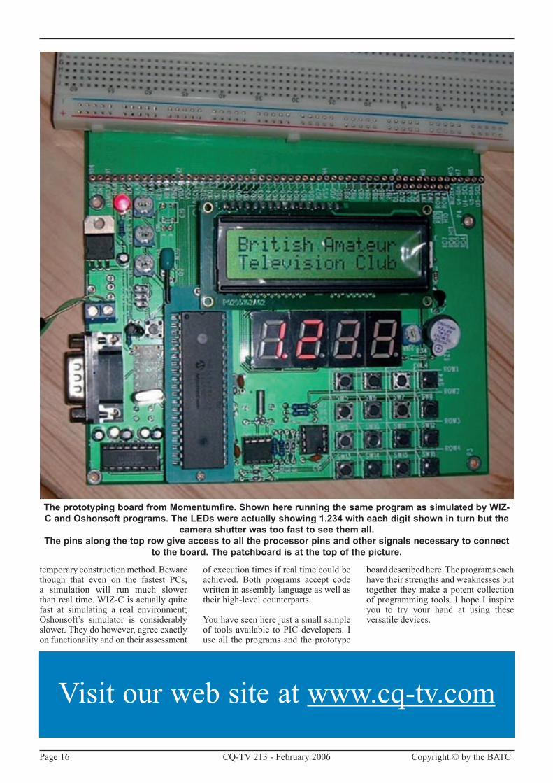
The prototyping board from Momentumfire. Shown here running the same program as simulated by WIZ-C and Oshonsoft programs. The LEDs were actually showing 1.234 with each digit shown in turn but the
camera shutter was too fast to see them all.The pins along the top row give access to all the processor pins and other signals necessary to connect
to the board. The patchboard is at the top of the picture.
Visit our web site at www.cq-tv.com

Copyright © by the BATC CQ-TV �13 - February �006 Page 17
By Brian Summers
Restoring an old broadcast television camera to working order is not something to be
undertaken lightly, it is not that it is very difficult, more that there is a lot of it! If you are fortunate enough to be contemplating an old camera channel, read on. If not many of the comments and techniques are applicable to other restoration items, even radios! This article is illustrated by a recently restored Marconi MkIII and many of the comments relate to the work done on it.
Where to start? I know it is a statement of the obvious, but you need to make sure you have all of it! Or at least enough to make a start. In general terms a camera channel comprises: -
A lens, zoom or fixed focal length. Fixed lenses go on a turret with 4
spaces (usually). Zooms have controlsor servo demand units. Lenses shouldhave rayshield hoods.
The Camera with its viewfinder, monocular or large, and viewfinder hood. Make sure the camera has all its internal plug in cards and modules, and that they are for the line (and colour)standard you want.
The CCU. Broadcast Cameras, except for the most recent models, connect to a CCU. Therefore, you will need the CCU and some cable of the correct type to connect them together. Multicore camera cable, with its co-ax cores, screened quads and single wires, is made to suit a particular camera or small rangeofcameras.Latercamerasused the Triax cable, which is still in use today, so it is hard or expensive to get!
Very early cameras had a separate PSU which connected to the CCU with more
cable. This is a standard multicore cable, but the connectors can be a challenge.LatermodelshadthePSUinthe same box as the CCU. If the PSU is of the switch mode type, they can be a challenge to fix.
The earliest cameras had the operators controls on the front of the CCU with only the most rudimentary provision for remote control. Then cameras had remote panel for operation of the controlswiredback to theCCU.Withthe arrival of the microprocessor, the OCP and RCP became simpler and a MSU dealt with the now vast range of adjustments for a single or group of cameras. The MSU is often missing and setup of a modern camera is difficult without it.
That is the basic camera channel, but there may be auxiliary units needed. If the camera is older than about 1975 it is likely to need “drive pulses1”from an SPG. Most important is the
The Care and Feeding of Vintage Broadcast Cameras
Figure 1. The Marconi MkIII camera

Page 18 CQ-TV �13 - February �006 Copyright © by the BATC
documentation. You will need the full handbooks or at the very least a full set of circuit diagrams and component layouts.
Safety NoticeYou should be aware that all tube type cameras have an interesting selection of high voltages in them, even the transistorised cameras have voltages of the order of 700 volts in them! This can give you a nasty nip, possibly fatal! If you are not trained in safe working practices, you should NOT be working on this type of equipment. Also note that the wiring practices of the 1950’s are a long way short of today’s standards. The use of a mains isolating transformer in addition to the Variac is recommended.
You should not work alone!
CleaningI give a fairly good clean before I start, using a paintbrush in conjunction with an airline blower to get the worst of the dirt and spiders out! Some things can then be washed, even components with a degree of care and then blown out again withtheairline.Somecameras(Pye&Marconi)havenice little labelson theindividualparts(R35C129etc)andcarehas to be taken with these labels as they come off very easily. I leave the paint touching up until later. There will be a lot of time to do this when various bits are being soak tested. The complexity of the chassis and wiring mean that it is not practical to strip units down for repainting or plating, as is often done with vintage radios. It is my view that this destroys the originality of the item under restoration. It is restoration not rebuilding.
PreservationI like to think I am saving these cameras for the future, so my approach is to replace as little as possible. Think of the“this ismygreatgrandfathersaxe,it’s only had two new heads and 4 handles” syndrome. The other thingthat really concerns me is keeping a channel complete. I have seen many instances were only the “photogenic”camera head is saved, the inconvenient CCU and PSU being lost for the future. To this end, I have been collecting complete cameras channels for my museum.
Components problemsPeople worry about valves but provided they have a good vacuum and light up they are probably going to work. Be careful when inserting and removing valves from their sockets, particularly
with octal� valves as the centre spigot can break off. If the pins are corroded you can clean them with a fibreglass brush(availablefromFarnelletc.)Thevalve sockets are normally OK as they would have been good quality ones and they last well. Gently rotate an old faulty valve in the socket, with a few drops of contact cleaner to clean the socket. Take care with Top Cap connections. It is annoyingly easy to break the cement holding it on. For B7G and B9A glass valves there is sometimes a metal pin straightening socket.
Transistors do age slowly and can give an interesting range of cracks, pops, hisses and leakage. If the camera has been in a damp area, the transistor connections (legs) can go rusty andthe transistor falls off. The wires are often plated steel, try a magnet! When sourcing replacements, if thecorrect type can’t be found, a substitute with suitable ratings will often work satisfactorily.
Tubes (pickup) Try to make sure youget the correct tubes with your camera. Spare tubes are about and can be found with some effort. Strangely, the later small size Plumbicons3 seem to be the hardest to find. Always keep the target (faceplate) uppermost whenhandling. Tubes do wear out, losing performance, with loss of emission and target deterioration. They rarely stop working completely and it is good to have some poor tubes for testing with as you can damage good tubes in a faulty camera.
Resistors go high in value, especially the green vitreous power kind. These go open circuit, and it seems to be a feature after 40 odd years, check them all! Small resistors of the carbon composition type also go high, but not all will need changing. The original types may be of 10% or �0% tolerance and the circuit may well work satisfactorily if the value has not changed too much. Variable resistors go intermittent and noisy. Try cleaning first and rotating
Figure 2. MkIII camera cable connector from 1953
Copyright © by the BATC CQ-TV �13 - February �006 Page 19
a lot.With use they often improve toa usable state. It is difficult to find suitable replacements.
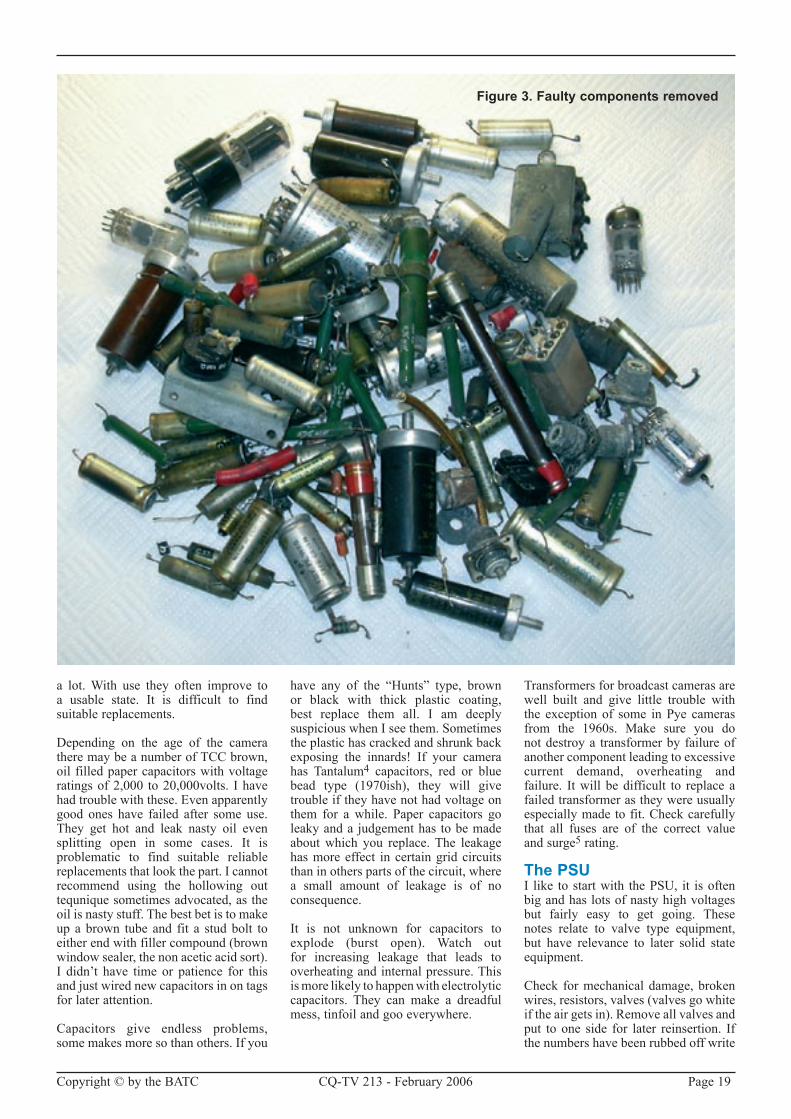
Depending on the age of the camera there may be a number of TCC brown, oil filled paper capacitors with voltage ratings of �,000 to �0,000volts. I have had trouble with these. Even apparently good ones have failed after some use. They get hot and leak nasty oil even splitting open in some cases. It is problematic to find suitable reliable replacements that look the part. I cannot recommend using the hollowing out tequnique sometimes advocated, as the oil is nasty stuff. The best bet is to make up a brown tube and fit a stud bolt to eitherendwithfillercompound(brownwindowsealer,thenonaceticacidsort).I didn’t have time or patience for this and just wired new capacitors in on tags for later attention.
Capacitors give endless problems, some makes more so than others. If you
have any of the “Hunts” type, brownor black with thick plastic coating, best replace them all. I am deeply suspicious when I see them. Sometimes the plastic has cracked and shrunk back exposing the innards! If your camera has Tantalum4 capacitors, red or blue bead type (1970ish), they will givetrouble if they have not had voltage on them for a while. Paper capacitors go leaky and a judgement has to be made about which you replace. The leakage has more effect in certain grid circuits than in others parts of the circuit, where a small amount of leakage is of no consequence.
It is not unknown for capacitors to explode (burst open). Watch outfor increasing leakage that leads to overheating and internal pressure. This is more likely to happen with electrolytic capacitors. They can make a dreadful mess, tinfoil and goo everywhere.
Transformers for broadcast cameras are well built and give little trouble with the exception of some in Pye cameras from the 1960s. Make sure you do not destroy a transformer by failure of another component leading to excessive current demand, overheating and failure. It will be difficult to replace a failed transformer as they were usually especially made to fit. Check carefully that all fuses are of the correct value and surge5 rating.
The PSUI like to start with the PSU, it is often big and has lots of nasty high voltages but fairly easy to get going. These notes relate to valve type equipment, but have relevance to later solid state equipment.
Check for mechanical damage, broken wires,resistors,valves(valvesgowhiteiftheairgetsin).Removeallvalvesandput to one side for later reinsertion. If the numbers have been rubbed off write
Figure 3. Faulty components removed

Page �0 CQ-TV �13 - February �006 Copyright © by the BATC
the number on the base with felt tip. Check the mains input voltage selector is correctly set! Check carefully that all fuses are of the correct value and surge rating.
Re-form6 the electrolitcs. Use an external variable HT power supplywithacurrentlimitingresistor(s)andacurrent meter. Connect to each capacitor in turn and start with a lowish voltage say 100 and watch the series current meter, which should fall to a low value. Whenithassettledincreasethevoltageand wait until it settles again. Repeat this until you have reached the working voltage of the capacitor. A certain amount of experience is needed to judge when electrolytic capacitors are satisfactory. A leakage of about 1mA. or lesswouldmostlybeacceptable.Watchout for parallel current paths which will make the leakage appear more than it really is. It is possible with some thought to do the re-forming without any disconnections. This is a good plan as the PSU, this article is based on, has 15 major electrolytics alone! At no time should the case of an electrolytic or any other capacitor get warm!
When you are happy with theelectrolytics and have oiled the fan, checked the insulation of the mains
input circuits and check that there are no short circuits cross the HT lines.You can apply some power. Use a Variac7 to bring the voltage up slowly and check the secondary voltages on themainstransformer(s).Itmaybethatyou will have to link two of the pins on the output connector as there is often an interlock to stop the PSU working if not connected to the CCU. If nothing has gone bang, plug the valves in and connect a dummy load to the output. This is important, as without a load the output voltage will go too high. I used a domestic 150w light bulb, it worked well and you could tell when the PSU was on! Check the regulation8 of the output voltages with different amounts of load. They should not change by more that a few percent (1% to 5%typicalrange).Settheoutputvoltage,Ilike to set it a bit low, perhaps �0 volts (for nominal 250v) low as it can beincreased later.
Most early PSU had meters for measuring the output currents and voltages. A very careful watch of the output current should be kept. It is likely that the current will rise as the camera warms up and the leakage of capacitors increases. If it goes up much or quickly switch off and investigate!!
The CCUMuch of what has been said about the PSU applies here. Remove the valves and re-form all the electrolytics, check resistors, small capacitors and look for wires off and damage. It is likely that the CCU has it’s own transformer for the 6.3volt heater supply, so if you connect thePSUtotheCCUandremovetheHTrectifiers you can plug the valves back inandpowerupwithnoHT from thePSU.UsethevariableHT,supplyusedfor re-forming the electrolitcs, to bring the voltage up slowly, looking for smoke as you go. It is a little known fact that most electronics works by smoke and if itescapesitstopsworking!Oh-Hum.
If your camera is a later solid state model you can do a variant on the above by plugging in the PCB cards one at a time watching for smoke. Remember the Tantalums! Make sure that you load the PSU suitably at all times so it is not upset by too little or too much load.
It’s about now that you can connect the SPGfeedsandseeifthereisanoutput?Some CCUs have to be fooled into thinking there is a camera connected. You could connect the camera at this stage in a minimalist way with most boards/units removed. Most CCUs have some arrangement for generating
Figure 4. The PSU before restoration started

Copyright © by the BATC CQ-TV �13 - February �006 Page �1
a local test signal and there is no point in working on the camera until the CCU is producing a correct output.
The video amplifier in the CCU processes the signal from the camera head, adding blanking9, clamping10, lift11, control of the gain, white clipping, and finally sync pulses are added. All these processes will have to work. See suggested reading list.
LatercamerasliketheMarconiMk8/9,the Phillips LDK5 and some Linkcameras are a bit all or nothing as regards getting the PSU/CCU/camera to work independently. You have to tread carefully.
The Camera HeadAs before inspect for mechanical damage, re-form electrolytics, etc. disconnect the viewfinder and lens for later attention. Remove the camera tube(s)notingcarefully theorientationin the scanning yoke1�. In a 3 or 4 tube colour camera you could consider just disconnecting the tubes, leaving
them in place. This will make later registration13 easier. Do not fiddle with the mechanical adjustment of the yokes for the same reason.
Image Orthicon cameras have +1400volts for the electron multiplier and –600volts around the Image section, mind your fingers! Plumbicon and vidicon cameras have 900 to 600volts on the wall anode. These voltages can come from the PSU or they can be locally generated in the camera.
Connect the camera to the CCU and having removed as much of the electronics as practical, bring the voltages up slowly watching for signs of distress or overheating. Plug the modules back in, checking things as you go.
If the camera has it’s own PSU get this working now. Middle period cameras, 1965 to 1980, often sent a single high power supply to the camera which was converted to the range of voltages needed in the camera.
It will be possible to inject a test signal into the camera at the start of the video amplifier and you should get this working first, through the camera and CCU to the output.
Then move on to the scanning sections, high voltage generators, scan failure protection circuits and focus supplies. Check the voltages at the tube base connections and also that the scanning generators are actually working before inserting or connecting the camera tubes.
During all the work in progress keep an eye on the total current drawn by the camera channel. It is hard to get it down to the value stated in the specifications. Hownearyouget to this isameasureof all the small leakages and extra valve current due to incorrect operating point caused by capacitor leakage or changed value resistors. A result of the extra current drawn is extra heat, leading to more leakage…
Figure 5. The CCU with it’s picture and waveform monitor above

Page �� CQ-TV �13 - February �006 Copyright © by the BATC
ViewfinderThe viewfinder is basically a small good quality picture monitor. Therefore normal monitor or TV servicing practice applies. Depending on the designers preferences and sometime the budget, the viewfinder can be more orless“standalone”oritcouldbemoreintegrated with the camera needing drive pulses and voltages from the camera. Cue lights and lens indicators are often integrated into the viewfinder. Late cameras could put textmessageson to the viewfinder.
There is a problem with viewfinders from about 1970. A faulty batch of 7 inch tubes with bonded on flat glass faceplates were manufactured. The trouble did not become apparent for � decades,butthe“gel”materialbetweenthe tube and the faceplate goes very spotty and strange. You will know it whenyouseeit.Latertubesofthesametype are unaffected.
Optical systemsThe lens focuses the image of the scene onto the target of the pickup tube(s).On its way, it has to be controlled in intensity and colour temperature. All broadcast cameras will have a means of controlling the tubes exposure, normally a servomotor driven iris14 In addition to the iris there will be a number of neutral density filters mounted in a rotating disk. This can be motor driven and controlled from the CCU. In colour cameras, a second ring contains coloured filters, minus blue or star filters. Turret cameras have 3 to 6 places for mounting lenses and when fitting
them the iris gear ring arrangement should be moved, so that all the lenses are set to the same aperture, say f8, so that the lenses track. The Zoom lens will have controls for zoom and focus with local servo or mechanical operation, the iris control being remotely controlled. In some cameras provision was made for local iris control.
The optical path should be cleaned with care using a lint free cloth. Great care should be taken with mirrors and prismatic light splitters. It may be better not to clean! Filters, lenses and tube faceplates are more robust. Clean with care.
Operation and AlignmentAt this point, the camera channel should be fault free, or nearly so. The scanning and video circuits must be working, as you will not get a picture if they are not satisfactory.CaptheLens15, insert and connect the tube(s).Donot adjust anyof the pre-set controls in the camera or CCU as they are likely to be set to the correct value, or nearly so.
Turn the Beam control(s) to zero andset other front panel controls to the centre or as dictated in the setting up instructions in the documentation.
Figure 6. The Marconi MkIII Viewfinder
Marconi MkIII brief data
Valves: 91 valves in total plus 3 CRTs and the camera tube.
Weight:170LBS(77Kgs.)cameraonly.
Power: 1000watts approximately
Modelswereavailablefor405lines,525/60linesand625/50linesandwith3”or4.5”tubes.
303 were made, 181 for the UK and the rest for export.
Camera Power Supply is the main power supply for the whole camera chain. It had a regulated output of �50volts DC at 1.�5A. and 330volts at 330mA.
Additionally there were some miscellaneous outputs at lower voltages. It used 17 valves for rectification and stabilisation. It came in two forms, rack mounting or in the mobile case form. In order to keep the weight down, in the mobile form, a forced air-cooled mains transformer was used.
For more information on the Marconi Mk III go to:- http://www.bsvideo.dsl.pipex.com/marconimk3doc.pdf

Copyright © by the BATC CQ-TV �13 - February �006 Page �3
All tubes, Vidicon, Plumbicon, Image Orthicons have a beam of electrons that scan over the tube’s target. Many of the adjustments are to do with controlling this process. The beam must have the correct current, be aligned, focused, and deflected to scan the correct target area and arrive at the target with the correct velocity. In addition, the Image Orthicon tube has an image section in front of the target with more controls.
There can be as many as 4 separate focus adjustments, optical, image (ImageOrthiconsonly),beamelectrostaticandbeam magnetic. Most tubes need an overall magnetic field, generated by a solenoid coil in the yoke with a stabilised current flowing in it and an adjustable voltage on the tube’s focus electrode. There can be more than one focus node of the electron beam within the tube, one of them will give the best performance.
When the camerahaswarmedup, say5 minutes, and the test signal from the camera is Ok turn off the test signal, un-cap the camera and advance the beam control. If you are really lucky, a picture will appear, more likely not. As you advance the beam control, watch the output picture for a change in brightness or noise level. This is the start of the beam landing on the target. Don’t use too much beam. It has to be enough, but too much will lead to poor results or even none. The correct point is to just“discharge thewhites” in thepicture.
If you have a colour camera from about 1975 onwards, it may have dynamic beam control to deal with light overloads which caused coloured trails to follow bright objects (comet tails).ThiswasvariouslycalledACTorHOP.The adjustment of these circuits must be correct or tube damage may result.
Make sure there is an optical image on the face of the tube and adjust the alignment and beam controls. Whensome sort of an image appears you can start the optimisation process. Image Orthicons have the image section to adjust as well. If there are no faults, maladjustment of the alignment and beam controls are the main reason for there being no picture.
A full line up of a camera can take a long time, a lot of experience and the manufactures set-up instructions should be followed. Colour cameras are much more complex as the coloured images have to match in amplitude, position and size. It helps a lot if you have not disturbed the optical positions of the 3 or 4 scanning yokes and tubes.
There is an alignment technique variously called minus Green (-G).This is used in the alignment of the image registration. The green signal is
GlossaryACT Anti Comet TailCCU Camera Control UnitCRT Cathode Ray TubeBG Burst GateFD Field DriveHOP HighlightOverloadProtectionHT HighTension(voltage)LD LineDriveLT LowTension.Invalveparlancelessthansay,10Vorlessthan100V
in solid state areas.MB Mixed BlankingMS Mixed SyncsMSU Master Setup Unit. Complex controls for a group of cameras.NTSC National Television Standards Committee, The American (60Hz.
Areas)coloursystem.OCP Operational Control PanelPS Pal Squarewave, also called VAS in BBC areas Vertical Axis SwitchRCP Remote Control Panel, normally a less complex version of the OCPSECAM The French colour system. SUB Subcarrier(sinewavesignal1voltPPk.)SPG Sync Pulse GeneratorTriax A coaxial cable with an extra overall insulated screen.PAL PhaseAlternateLine,theEuropean(mostly)coloursystemPSU Power Supply UnitVAS In BBC areas Vertical Axis Switch also called pal switch in other
areas
Suggested reading listPractical Television Engineering, byScottHelt, Pub. Rinehart Books 1950Television Engineering, by Amos and Birkinshaw,
Vols. 1 to 4 Pub. Iliffe 1953*
Basic Television, by Bernard Grob Pub.McGraw-Hill 1954TelevisionEngineeringHandbook, by Donald Fink Pub.McGraw-Hill 1957Sound and TV Broadcasting by K R Sturley Pub. Iliffe 1961*PrincipalsofPALColourTelevision byHVSimms Pub. Iliffe 1969*Television measurement techniques byLEWeaver Pub.PeterPeregrinusLtd 1971*VideoHandbook,secondedition byRuVanWezel Pub.Heinemann:London 1987
All of the above are heavy-duty technical handbooks, even the early valve ones have principals still in use today. * These books have been published in conjunction with the
BBC and issued as training books.

Page �4 CQ-TV �13 - February �006 Copyright © by the BATC
inverted and added to either the red or thebluesignal.Wherethepicturesarein registration the signals will cancel to grey, the errors showing as bright edges. This is best displayed on a good underscanning16 monochrome monitor.
Test GearYou will need the usual set of servicing tools, testmeters, one digital and one analogue, an oscilloscope with at least 20MHzbandwidth.
A Megger with �50v & 500v operation for measuring capacitor leakage.
HTpowersupply,adjustablefrom100vto 450v at, at least 100mA.LT powersupply 0 to 50 volts �A.
AnLCRbridge.
A good monochrome picture monitor and a colour monitor as well if you have a colour camera.
A TV waveform monitor17 and a vectorscope18, TV test signal generator, an SPG.
A selection of test cards and an illuminated stand for them.
NotesExperts and purists should note that there are many simplifications in the foregoing texts.
Footnotes1 Drivepulses: (or justpulses)refers to theoutputpulsesfromacentralSPGusedtocontrol the timingofagroupof
cameras.Mostcamerasusedasubsetofthefullsetofsevenpulses,dependingontheageandtype.(LDFDMBMSBGPSSUB)
� Octal: In this usage a valve with an 8 pin Bakelite base, glass or metal body
3 Plumbicon: A lead Oxide based camera tube made by Philips Trademark.
4 Onthispointifyouhavea“working”camerawiththeseredorblueTantalumcapsinit,itisagoodideatopoweritupevery few months to stop them going bang! Very tedious as it is likely to have dozens or even hundreds of them.
5 Surge:Inthiscontextfusescanbe“quickblow”or“slowblow”surgeresistanttypes.
6 Re-forming electrolytic capacitors, is a process of restoring the insulating layer to its original value by applying a voltage which is slowly increased.
7 Variac: A variable voltage auto transformer. Note that it is not an isolating transformer. The voltage is adjustable from 0 to �60 volts. It should have a current rating of at least � amps, ideally 5 amps.
8 Regulation: Refers to how well a stabilised power supply controls its output voltage.
9 Blanking: The raw picture from the camera is oversize and the edges are often poor, so these are blanked off to give nice crisp edges and a picture of the correct size.
10 Clamping: A process of picture stabilisation to give a defined black level.
11 Lift:Theadjustmentoftheblacklevelinthepicture.
1� Scanning Yoke: In a broadcast camera this is a precision wound set of coils to do the horizontal and vertical deflection of the electron beam. There will be coils for adjusting the beam alignment, and overall beam focus.
13 Registration: The adjustments needed to make the scanned patch in each of the colour cameras tube match so that the coloured images are in alignment.
14 Iris: An arrangement of moving vanes to present a circular aperture of variable size in the light path of a lens
15 LensCap:Anopticalblankingarrangementtostoplightreachingthetube(s).Itisliterallyacapontheendofthelens,but sometimes there is a blank position on the filter wheel or the lens iris can fully close.
16 Underscanning: On a picture monitor tube the amplitude of the scanning is reduced to show the edges of the picture. Engineering picture monitors are normally operated in this mode. There should be a switch for it.
17 Waveformmonitor:Aspecialisedoscilloscopefordisplayingtelevisionwaveforms.
18 Vectorscope:Aspecialisedoscilloscope toshowtheamplitudeandphaseof thecoloursubcarrier inacodedPALorNTSC signal.

Copyright © by the BATC CQ-TV �13 - February �006 Page �5
By Graham Shirville - G3VZV
As many members will remember, a campaign for funds was launched earlier this year to
sponsor the addition of two antennas to be fitted on the outside of the new Columbus module which is scheduled to be added to the International Space Station in �007 or �008. This campaign has been successful and sufficient donations were collected to finance the manufacture of antennas for two bands. Each antenna will be identical and each will coverbothL-banduplinks (1260-1270MHz) and S-Band downlinks(2400-2450MHz).
These antennas will be fitted underneath the module so that they are facing the earth. They will be transported to the ISS in the cargo bay of an American Shuttle. Since there is little room left between the module and the shuttle cargo bay doors, the ARISS antennas will be patches which only project a few millimetres. These patches will be fixed to the external Meteorite Debris Panels (MDP) which protect the hullof Columbus. On the conical end of the module, where it attaches to the ISS main structure, feedthroughs have been installed for the coax feeds to the antennas themselves.
The debris panels can be seen in Fig 1 and a small illustration of the patch antennas is shown in Fig �.
The existing ARISS antennas on the Service Module are shared through diplexers and will not be especially effective on the microwave bands. Using the dedicated antennas on Columbus will, for the first time, permit viable ARISS operations on these useful bands.
With the Columbus module beinglocated at some considerable distance from the other two ARISS stations, this will permit parallel operations on the new bands at the same time as the existing operations.
The availability of these new frequencies will enable us to establish wideband and video operations for the first time. This facility will provide ATV facilities for School contacts and, additionally, continuous transponder operation.
The Columbus module is designed to undertake experiments but may also be used as temporary sleeping accommodation for the European astronauts. It is anticipated that most, if not all of them, will be licensed amateurs.
Different sleep patterns of the astronauts can restrict the existing operations so this “remote” facilitywouldovercomethis constraint.
To summarise, the addition of these new antennas will provide greatly enhanced opportunities for amateur radio operations on the ISS and an additional emergency communication facility for the astronauts.
The antennas have been developed by the Institute of Telecommunications and Acoustics of the Wroclaw Universityof Technology in Poland and they are expected to be installed onto the Columbus module at the EADS facility in Bremen Germany in January orFebruary �006.
The Columbus has a length of eight metres and a diameter of 4.5 metres. It will be equipped with ten standardised payload racks to accommodate experiment equipment. In addition, there will be three system racks, which, for instance, will serve for water supply control,andthreestorageracks.Launchmass of Columbus will be almost 13 tonnes including a payload mass of �.5 tonnes. The laboratory provides sufficient space for three crew members to carry out research under microgravity conditions. Columbus is designed for a total service life of 15 years.
One new acronym has had to be created! As well as the Columbus module,
A progress report on the ATV project for the ISS
Figure 2
Figure 1

Page �6 CQ-TV �13 - February �006 Copyright © by the BATC
ESA are also developing a number of “AutonomousTransferVehicles”whichwill ferry equipment and stores to the ISS on Ariane 5 launch vehicles. These are, of course referred to as ATVs and wecannotreallyuseATVfor“AmateurTelevision” without a large amountof confusion being created. Therefore ATV on the ISS is going to be referred to as the“AmateurVideoSystem”orAVS for short.
A possible block diagram of the complete system is shown below and
a meeting is expected to be held in Bremen in February or March to further the development of it. It is not expected that the Columbus module will actually be launched with the AVS gear already installed – we expect that this will be delivered to the ISS on a later flight – maybe in one of the ATVs!
As can be seen, this system would provide a wideband linear transponder for both analogue and digital signals, an AVS(akaDATV)systemfordownlinkand maybe uplinking and, of course, a
local video camera and microphone for the use of the astronauts.
The development team for this work includes the following amateurs: Gaston Bertels -ON4WF, OliverAmend - DG6BCE, Florio dalla Vedova -IW2NMB,PaoloPitacco-IW3QBN,Graham Shirville - G3VZV, Dave Mann –G8ADM,CarlosEavis,-G0AKI,JasonFlynn – G7OCD, Christophe Mercier, Wolf-HenningRech-DF9IC.
Figure 3
Caption competition 212 resultand the winner is:-
‘A DAB hand with a S.O.A.R head ‘ sentinbyTomRoberts,GW0WHT
Some other entries received were:-“Ohgroan,toomuchforeheadreflection...WHERE’SMAKEUP?” FromMikeG8LES
“WishIcouldrememberwhereIputtherestofmybody”.. FromRalphWGabbitas...G3KHU...exG6AFN-T..
“Whatabrilliantidea” FromPeterJohnsonG4LXC.
‘Well,Iusedtohavemorehairthanthis!Where’sitallgone?’ FromEricGW8LJJ,stillwithafullheadofhair(just)!

Copyright © by the BATC CQ-TV �13 - February �006 Page �7
By John Lawrence GW3JGA
A Bar Display Audio Level Meter
An audio level meter is usually fairly low down the priority list of equipment in the ATV
shack. This is probably because most camcorders(usedasthestationcamera)have a built-in automatic audio level circuit which provides a fairly constant level audio output. Once the audio sub-carrier deviation at the transmitter has been set, it can usually be left alone. However, if you use several differentaudio sources, VCR, DVD, separate microphone, etc. then an audio level meter is useful for setting deviation and avoiding reports of distortion or low sound.
Display DriverThe audio level meter to be described is based on the National Semiconductor Dot/Bar Display Driver I.C. It senses an analogue voltage level and drives 10 LEDs or other types of displays.There are three versions available,
Circuit Notebook No. 88
Figure 2 - Bar display, single bar
Figure 5 - Bar numbers versus signal level

Page �8 CQ-TV �13 - February �006 Copyright © by the BATC
the LM3914, which provides a lineardisplay proportional to input signal, the LM3915,whichprovidesalogarithmicdisplayandtheLM3916whichprovidesa display equivalent to a ‘VU’ meter. Full details of the I.Cs are given in the National Semiconductor data sheet [1] which also includes lots of application information.
TheLM3915hasbeenchosen for thislevel meter and each bar on the 10 bar display represents a change of 3dB in the input signal level. An application circuit is shown in Fig.1. It is possible to feed an audio signal directly into the LM3915 as it will respond to theinstantaneous positive value of the waveform, but the results using this method are rather disappointing.
Ideally, the input requires a d.c. voltage proportional to signal level, so the audio signal first needs to be rectified. The display driver can be configured by pin 9, to give either a single bar (pin 9 no connection) shown in Fig.2,oracolumnofbars(pin9to+12V)as shown in Fig. 3. The bar display shown is intended for audio application andhasthetopthreebars(8,9,&10)red and the others (1 to 7) green.Thedisplay is RS components �47-3107. Alternatively, any 10 bar display could be used.
Audio signal rectifierThere are plenty of rectifier circuits and ‘absolute value’ circuits which would be suitable, including those given in the data sheet, but most use op-amps which require both positive and negative supplies [�][3]. The intention was to operate everything from a single +1�V
supply and to avoid the use of a DC-DC converter for generating the dual polarity op-amp supplies.
The complete circuit is shown in Fig. 4. The overall sensitivity for ‘full scale’ is -20dBm (77mV rms).At the input,R1, R� & R3 provide an attenuator to allow -10 dBm and 0dBm to be accommodated. The audio signal is
amplified by IC1 (741 or similar),the gain can be adjusted over a �0dB range by RV1, to allow calibration or setting up at some alternative or more convenient signal level.
The output signal from IC1 is half-wave rectified by D1 and the peak value stored in C4. To compensate for the diode turn-on characteristic, a
Figure 1 - LM3915N Bar Display Driver
Figure 4 - Circuit diagram

Copyright © by the BATC CQ-TV �13 - February �006 Page �9
Figure 3 - Bar display, column of bars
Figure 6 - Close-up of Bar Display

Page 30 CQ-TV �13 - February �006 Copyright © by the BATC
small positive bias voltage is provided by the voltage drop across D� and the potentiometer RV�. In operation, RV� sets the no signal condition to just below the illumination of bar 1 and RV1 the full scale with bar 10 illuminated. The relationship between signal level and illuminated bars is shown in Fig. 5. The accuracy is adequate down to about -30dB with slight errors below this.
The voltage across C4 is taken to the input of IC�. The ‘attack’, or rise-time of the display is quite short and the ‘decay time’ is about 0.3 seconds determined by R10 which is connected across C4.
On IC�, the display driver, R11 and R1� define both the current through each of the LEDs and the input sensitivity.Withthevalueschosen,aninputsignalof +3.� volts to pin 5 gives a full scale display(bar10).
OperationConnect the meter at the most appropriate place, for example, the audio input to the transmitter or the audio output of the receiver.
Calibrate the meter by setting RV� so that under ‘no signal’ conditions, bar 1 is almost but not quite illuminated. Then, at the required level of signal, adjust RV1 for the appropriate bar to be illuminated. For example, you might set up your transmitter for full deviation and then adjust RV1 for illumination of Bar 10.
The circuit has only been constructed on a plug board so its susceptibility to RFI has not been checked. There are many web sites expressing strong opinions on average reading VU meters versus Peak Programme meters and how they should be calibrated. This level meter
hasbeentestedusinga1kHzsinewaveand is for general purpose amateur use.
References[1] LM3915Dot/BarDisplayDriver
National Semiconductor Application report www.national.com/pf/LM/LM3915.html
[�] Detector and rectifier circuits As above Figs 1, �, & 3
[3] Precision rectifier circuits ICOp-AmpCookbook,WalterG.Jung HowardW.SamsISBN0-672-��453-4 p.�37
By Richard L. Carden VK4XRL
A Simple Amateur Television Ident Server for home or repeater use
Wearealwayslookingfornewprojectsto stimulate the ATV scene here in Brisbane,Australia.When surfing theinternet one day I then came across an interesting article from Jean-FranciFourcadie, F4DAY. He had an articletitled “produce a Generator of videotest-card using the SanDisk Viewer.”This looked very interesting as it also could be used on a repeater site. I also had a 8Mb compact Flash card which was spare that came with my digital camera. As it happened a SanDisk Viewer was being sold on EBay, so
now I had all the required parts to make up this project.
The first thing was to make up some idents using pictures I had, plus some test-cards to put on the CF card. The Idents and Testcards were modified using Photoshop where captions and call signs were added, also image sizing could also be carried out. With thesoftware that came with the digital camera it allowed me to upload these images onto the CF card via the camera. Since starting this project I have required a card reader and writer which simplifiers the loading to the CF card. Having done this the next thingto do was to checkout the unit via the CRO and picture monitor. The pictures subjectively looked fine but the CRO showed a different story. The sync to picture ratio was appaualling. F4DAY
does mention this problem and suggests changing R38 and R35, however no values are given.
R�8 whose original value is 75r was in my case changed to 56r (this will effect the amplitude)while R35 whose original value is150rwaschangedto82r(thiseffects the amplitude of the synchronization pulse levels).One problem with these changes is that the overall vision level is now only 250mv P/P (or
thereabouts). What I then did was tofeed this via a VDA using a very short cable left unterminated and adjusted the VDA for 1v p/p. The chroma amplitude is also a little low but this hasn’t been a problem as my Panasonic AV5 mixer will compensate for this. Away around thisistousetheS-VHSoutputandusetwo amplifiers one for luminance and the other for chrominance gain. Combining these will produce a composite output (notethishasn’tbeentriedbuttheideashouldwork).
The composite project doesn’t take long to get you up and running. The overall effort enhances the ATV output and therefore makes a very nice addition to the ATV station or repeater. Other units haven’t been tried at this stage, however if anyone does please drop a line to the editor letting all know what problems you have had.
You’re Been Served
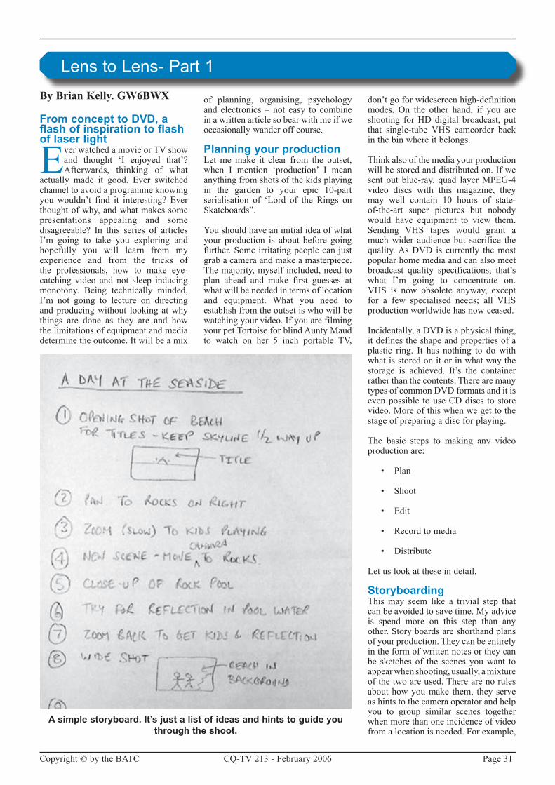
Copyright © by the BATC CQ-TV �13 - February �006 Page 31
By Brian Kelly. GW6BWX
From concept to DVD, a flash of inspiration to flash of laser light
Ever watched a movie or TV show and thought ‘I enjoyed that’?Afterwards, thinking of what
actually made it good. Ever switched channel to avoid a programme knowing youwouldn’t find it interesting? Everthought of why, and what makes some presentations appealing and some disagreeable? In this series of articlesI’m going to take you exploring and hopefully you will learn from my experience and from the tricks of the professionals, how to make eye-catching video and not sleep inducing monotony. Being technically minded, I’m not going to lecture on directing and producing without looking at why things are done as they are and how the limitations of equipment and media determine the outcome. It will be a mix
of planning, organising, psychology and electronics – not easy to combine in a written article so bear with me if we occasionally wander off course.
Planning your productionLetmemake it clear from the outset,when I mention ‘production’ I mean anything from shots of the kids playing in the garden to your epic 10-part serialisation of ‘Lord of the Rings onSkateboards”.
You should have an initial idea of what your production is about before going further. Some irritating people can just grab a camera and make a masterpiece. The majority, myself included, need to plan ahead and make first guesses at what will be needed in terms of location and equipment. What you need toestablish from the outset is who will be watching your video. If you are filming your pet Tortoise for blind Aunty Maud to watch on her 5 inch portable TV,
don’t go for widescreen high-definition modes. On the other hand, if you are shooting forHDdigital broadcast, putthat single-tube VHS camcorder backin the bin where it belongs.
Think also of the media your production will be stored and distributed on. If we sent out blue-ray, quad layer MPEG-4 video discs with this magazine, they may well contain 10 hours of state-of-the-art super pictures but nobody would have equipment to view them. Sending VHS tapes would grant amuch wider audience but sacrifice the quality. As DVD is currently the most popular home media and can also meet broadcast quality specifications, that’s what I’m going to concentrate on. VHS is now obsolete anyway, exceptfor a few specialised needs; all VHSproduction worldwide has now ceased.
Incidentally, a DVD is a physical thing, it defines the shape and properties of a plastic ring. It has nothing to do with what is stored on it or in what way the storage is achieved. It’s the container rather than the contents. There are many types of common DVD formats and it is even possible to use CD discs to store video. More of this when we get to the stage of preparing a disc for playing.
The basic steps to making any video production are:
• Plan
• Shoot
• Edit
• Record to media
• Distribute
Letuslookattheseindetail.
StoryboardingThis may seem like a trivial step that can be avoided to save time. My advice is spend more on this step than any other. Story boards are shorthand plans of your production. They can be entirely in the form of written notes or they can be sketches of the scenes you want to appear when shooting, usually, a mixture of the two are used. There are no rules about how you make them, they serve as hints to the camera operator and help you to group similar scenes together when more than one incidence of video from a location is needed. For example,
Lens to Lens- Part 1
A simple storyboard. It’s just a list of ideas and hints to guide you through the shoot.
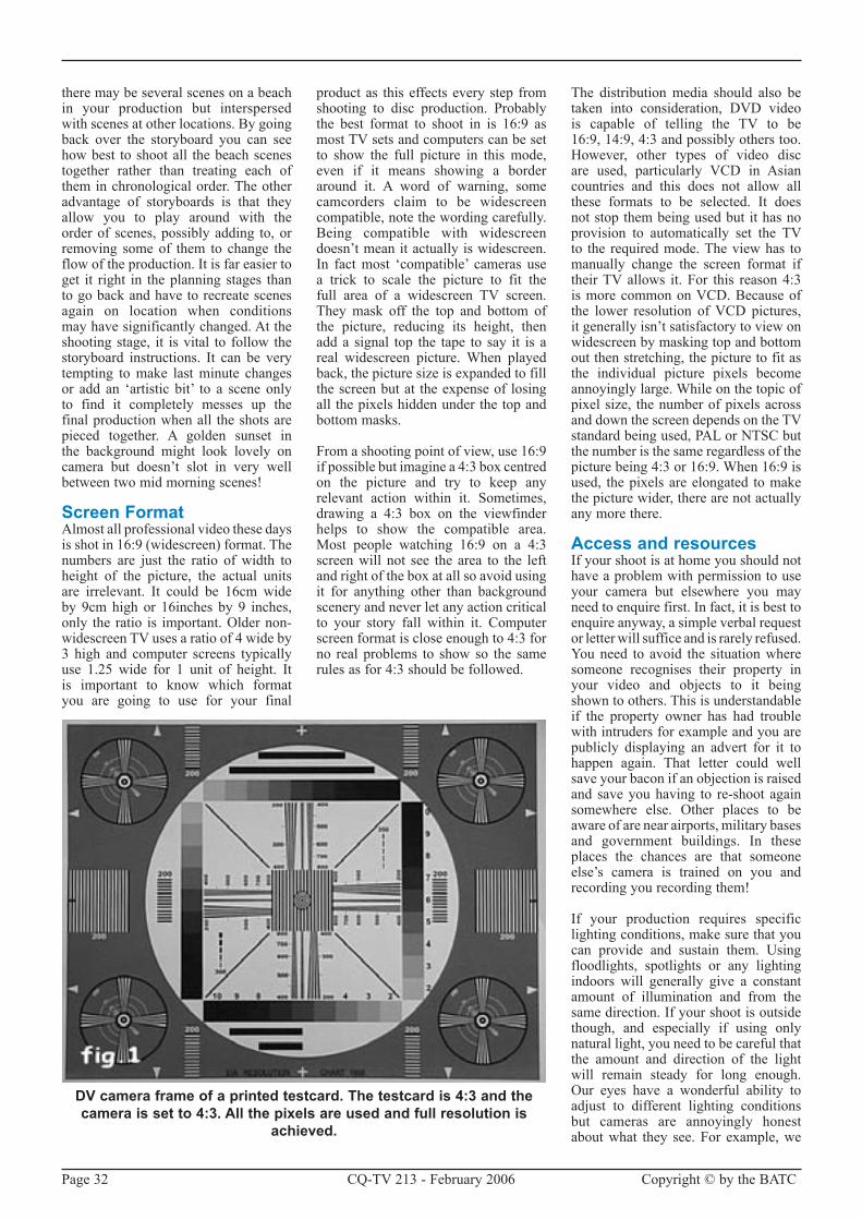
Page 3� CQ-TV �13 - February �006 Copyright © by the BATC
there may be several scenes on a beach in your production but interspersed with scenes at other locations. By going back over the storyboard you can see how best to shoot all the beach scenes together rather than treating each of them in chronological order. The other advantage of storyboards is that they allow you to play around with the order of scenes, possibly adding to, or removing some of them to change the flow of the production. It is far easier to get it right in the planning stages than to go back and have to recreate scenes again on location when conditions may have significantly changed. At the shooting stage, it is vital to follow the storyboard instructions. It can be very tempting to make last minute changes or add an ‘artistic bit’ to a scene only to find it completely messes up the final production when all the shots are pieced together. A golden sunset in the background might look lovely on camera but doesn’t slot in very well between two mid morning scenes!
Screen FormatAlmost all professional video these days isshotin16:9(widescreen)format.Thenumbers are just the ratio of width to height of the picture, the actual units are irrelevant. It could be 16cm wide by 9cm high or 16inches by 9 inches, only the ratio is important. Older non-widescreen TV uses a ratio of 4 wide by 3 high and computer screens typically use 1.�5 wide for 1 unit of height. It is important to know which format you are going to use for your final
product as this effects every step from shooting to disc production. Probably the best format to shoot in is 16:9 as most TV sets and computers can be set to show the full picture in this mode, even if it means showing a border around it. A word of warning, some camcorders claim to be widescreen compatible, note the wording carefully. Being compatible with widescreen doesn’t mean it actually is widescreen. In fact most ‘compatible’ cameras use a trick to scale the picture to fit the full area of a widescreen TV screen. They mask off the top and bottom of the picture, reducing its height, then add a signal top the tape to say it is a real widescreen picture.When playedback, the picture size is expanded to fill the screen but at the expense of losing all the pixels hidden under the top and bottom masks.
From a shooting point of view, use 16:9 if possible but imagine a 4:3 box centred on the picture and try to keep any relevant action within it. Sometimes, drawing a 4:3 box on the viewfinder helps to show the compatible area. Most people watching 16:9 on a 4:3 screen will not see the area to the left and right of the box at all so avoid using it for anything other than background scenery and never let any action critical to your story fall within it. Computer screen format is close enough to 4:3 for no real problems to show so the same rules as for 4:3 should be followed.
The distribution media should also be taken into consideration, DVD video is capable of telling the TV to be 16:9, 14:9, 4:3 and possibly others too. However, other types of video discare used, particularly VCD in Asian countries and this does not allow all these formats to be selected. It does not stop them being used but it has no provision to automatically set the TV to the required mode. The view has to manually change the screen format if their TV allows it. For this reason 4:3 is more common on VCD. Because of the lower resolution of VCD pictures, it generally isn’t satisfactory to view on widescreen by masking top and bottom out then stretching, the picture to fit as the individual picture pixels become annoyinglylarge.Whileonthetopicofpixel size, the number of pixels across and down the screen depends on the TV standardbeingused,PALorNTSCbutthe number is the same regardless of the picturebeing4:3or16:9.When16:9isused, the pixels are elongated to make the picture wider, there are not actually any more there.
Access and resourcesIf your shoot is at home you should not have a problem with permission to use your camera but elsewhere you may need to enquire first. In fact, it is best to enquire anyway, a simple verbal request or letter will suffice and is rarely refused. You need to avoid the situation where someone recognises their property in your video and objects to it being shown to others. This is understandable if the property owner has had trouble with intruders for example and you are publicly displaying an advert for it to happen again. That letter could well save your bacon if an objection is raised and save you having to re-shoot again somewhere else. Other places to be aware of are near airports, military bases and government buildings. In these places the chances are that someone else’s camera is trained on you and recording you recording them!
If your production requires specific lighting conditions, make sure that you can provide and sustain them. Using floodlights, spotlights or any lighting indoors will generally give a constant amount of illumination and from the same direction. If your shoot is outside though, and especially if using only natural light, you need to be careful that the amount and direction of the light will remain steady for long enough. Our eyes have a wonderful ability to adjust to different lighting conditions but cameras are annoyingly honest about what they see. For example, we
DV camera frame of a printed testcard. The testcard is 4:3 and the camera is set to 4:3. All the pixels are used and full resolution is
achieved.

Copyright © by the BATC CQ-TV �13 - February �006 Page 33
perceive items to be the same colour when viewed in daylight or artificial light but a camera would see things tinted blue or yellow under the same conditions. If you want to see how much we adjust our eyesight, try pointing a camera at a colourful object such as a flower and flick the white balance switch between its different settings, the amount of compensation the camera adds is amazing. If your shoot is likely to take more than an hour or so you may need to take into consideration that shadows will have moved. If this is the case, you may do well to shoot over more than one day so similar lighting directions can be expected. Keep an eye on the weather forecast if you do this or you may find your shadows have disappeared anyway!
Most shoots will need at least two cameras. You can manage with one but it is far more difficult to keep sound and picture in sync when shifting from one view to another. Take for example the classic TV dialogue between interviewer and interviewee, unless you can persuade them to freeze while you move the camera from looking at one face to the other, you will have a discontinuity. Nobody wants to see the effect of the camera swinging about and re-focussing because it distracts from the topic of conversation. Whatyou would typically do is use two
cameras, one trained on each person but only use one sound track. The sound could be from just one of the cameras or a mix from both or could be from a separate microphone. The sound would eventually run all the way through while the video would cut from one camera source to the other. The last thing you want is different background noises and tonal quality as you switch camera scene so keep to the same sound recording throughout if possible. If fixing is necessary to mask sound problems or align lip-sync it can be done at the editing stage which we will be visiting later.
For static shots always use a tripod, even with the ‘anti-shake’ facilities on newer cameras you still see some movement. There are two kinds of anti-shake cameras, one uses a mechanical damping system that actually moves the CCD and/or the lens structure so it can move independently of the camera body. The other system uses electronic compensation where the corner coordinates of the image are moved so the window they define appears to be stationary. The latter system often gives poorer performance, both because it sometimes misjudges which parts of the picture should and should not be in motion and because they ‘steal’ pixels from the image border to allow
the slightly smaller visible window to move within the full sized picture.
If tripods are not appropriate, for example when the camera is travelling or is being used where the ground is too uneven, try to make it as heavy as you can manage. This may sound crazy when manufacturers strive to make cameras as lightweight as possible but the extra mass will dampen any sudden movement very effectively. Remember though, that the accessory sockets and mounting screw have limited strength so don’t hang house bricks on the headphone jack!
Finally, don’t forget the human element, two cameras probably need two cameramen!
Choice of cameraYou don’t have to look far to see adverts for cameras and camcorders, all the daily newspapers and magazines are full of them and they all claim to be best. To some degree the claims are probably true, some cameras are best at some jobs, others are better at other jobs.Whatyouneedtodecideiswhichhas all the facilities you need for your productions and of course which is within your budget.What certainly istrue is that most new camcorders, even at the budget end of the scale, surpass
Exactly the same testcard and camera position as fig.1 but with the camera set to 16:9 mode. The picture size is correct but note that the top and bottom of the image are cropped. Because the cropped area is
missing, the remaining pixels have been stretched to maintain the picture size. Fewer pixels implies lower resolution.

Page 34 CQ-TV �13 - February �006 Copyright © by the BATC
the quality of professional cameras of only 5 or 6 years ago.
Some cameras record to tape, some directly to DVD media, let’s look at the pros and cons of each of the common types.
VHS – awful definition, poor colourrendition, poor sync stability. About �40 lines of resolution. Not a lot going for it really.
SVHS–recordschromaandluminancesignals separately which greatly improves resolution and colour quality. Resolution increases to about 400 lines. Tapes are fairly expensive.
VHScandSVHSc–thesameasVHSand SVHS in terms of quality but insmaller cases and with shorter running time.
Beta – plagued by so many different and incompatible types. Good to excellent quality, bulky tapes and expensive. ‘max’ and low band formats give about 350 lines of resolution, high band gives about 500.
MiniDV – digitises the picture and records the numbers. Excellent quality, small and very inexpensive tapes. MicroDV is an even smaller variant of the same system. Around 500 lines of resolution.
DVCAM – exactly the same recording method as MiniDv and MicroDV but uses a larger tape format with wider recording tracks to make drop-out less likely. This is probably the most widely used professional format at the moment.
DVD – excellent picture quality, media costs pennies. A serious drawback though is that they compress the picture using MPEG� technology. This maximises the recording time but makes the resulting video very difficult to edit afterwards. Resolution depends on picture content but around 400 lines.
The type of imaging device plays a large part in the picture quality. Older vacuum tube types tended to give poor quality and suffered colour drift as the three tubes aged at different rates. They also tended to suffer from ‘ghost’ after images and trails following bright spots in the picture. Thankfully, most of these cameras have been ‘retired’ from service; I have seen them on sale for £5 and nobody taking interest in them!LatercamerasuseCCD(ChargeCoupledDevice)sensorsthataremuch
smaller and give dramatically better results. The issue now is whether to use a single CCD camera or a three-CCD camera. A camera with a single CCD uses a striped colour filter in front of the sensor. The stripes are arranged so they filter out unwanted colours from the image before the light falls on the sensor surface. One stripe passes red colours, one green and one blue. The area on the CCD chip on which each colour lands is electronically routed to the appropriate colour processing circuits. In a three chip system, instead of seeing each colour through a striped filter, the whole image is split and passed through optical filters, each allowing only one colour through to one of the CCD chips. This system gives better definition as the image isn’t divided into three regions on one sensor but one region on three sensors. The downside is of course three times as many CCDs and processing circuits are needed so the cost is much higher. In my own opinion, the better quality is worth paying for.
No matter how many CCDs the camera has, they still have to be scanned to read the light levels focussed on each pixel of the chip. Two scanning methods are used, progressive scan and interlaced scan. Normal TV pictures are interlaced, that is, the even numbered lines and odd numbered lines are scanned alternately. Computer screens normally are progressively scanned, meaning all the lines are sequentially scanned from top to bottom of the picture. Mixing the two can give strange results. If you view progressive on an interlaced system and vice versa you see an effect rather like the teeth of a comb to the sides of moving objects. The teeth are on alternate scan lines and are caused because of the time delay between the odd and even scans of the CCD. Even at 50 or 60 scans per second, there can be significant movement in the target object between scans. When viewedon the wrong system, the image from the odd and even scans are displaced bytheamountthetargetmoved.Whenit is necessary to use the other scan system there are usually options to counter the effect. The simplest way is simply to discard either the odd or the even scan lines and duplicate the other ones in their place. It halves the vertical resolution but is still more pleasant to the eye. Most professional cameras use progressive scan so they are compatible with computer displays and high-end editing facilities. It is easy to convert progressive scanned pictures to interlaced ones for TV use but difficult to convert the other way around so
being more versatile, progressive scan is the preferred system.
Regardless of how the picture is stored in the camera, you still have to be able to transfer it somewhere else to be edited. On most cameras there is a video and audio output which can be connected straightintoaTVset.Whilethiscouldbe very useful for monitoring your shot on a bigger screen and listening to your audio on headphones or through an amplifier, it isn’t really satisfactory for recovering your shoot so it can be edited or even viewed at home. The reason is simple, the playback is analogue and will be encoded into NTSCorPALcompositevideoformatwhich limits the usable bandwidth. In the ‘capture’ process where the video is transferred to the editing facility, the encoded signal has to be decoded back to colour and luminance information, further limiting the bandwidth and adding other undesirable conversion effects. The solution to the problem is not to use analogue at all, use DV format whenever possible. Many models of DV cameras are available and as their popularity grows, analogue formats are being squeezed out of the market. DV, being digital is not compromised by the effects of tape drop-outs (unlessvery severe) and is relatively immuneto minor tape transport variations, the effect that causes noise bands and pulling onVHS tapes.When it comesto transferring DV to computer for editing there are two choices, USB and IEEE1394(alsoknownas“i.Link”and“FireWire”), both connect by a thincable. USB comes in two types, plain USB and USB�, the original ‘plain’ type is unsuitable for serious video work as its data carrying speed is much lower than needed for anything but the lowest quality video. USB� does work fast enough for good quality video but the best performance comes from the IEEE1394 interface. This is the one to look for if you are buying a new camera or camcorder. Newer Apple computers have IEEE1394 sockets built in to them, on PCs, an extra card will usually have to be fitted but these only cost about £10. Incidentally, there is absolutely no difference in quality whatsoever between cheap and expensive IEEE1394 cards so go for the lowest cost one you can find.
When shooting at home, poweryour camera from a mains adapter if possible. Before doing any serious filming though, make a short trial video of a plain mid-grey background and under quiet conditions to make sure you do not have video hum bars

Copyright © by the BATC CQ-TV �13 - February �006 Page 35
or sound buzzing. You will see these when playing the tape back more than when recording. If you are using a computer to edit your video, try playing back into the computer beforehand too because sometimes a ground loop can be created through the cables and this can also cause hum problems. Running from batteries will of course remove any possibility of ripple in the supply voltage but do be careful that you have enough power capacity to complete your work. Older cameras used Nickel-Cadmium batteries which had an annoying tendency to work fine then suddenly go dead without warning. Lithium Ion batteries are much betterat giving warning before dying and often, inside the battery casing, a small monitoring circuit checks the remaining power level and reports it back to the camera. Don’t do what I did once – make a whole recording with the battery level icon superimposed on the picture !
Going back to the visual aspect of shooting, most cameras have evil functions in them called ‘Automatic Level Control’ and ‘Automatic WhiteBalance’. These are fine and can be useful if you have to shoot without prior setting-up, for example if you spot something unusual and just have to capture it quickly. For more serious work, turn these off and manually set the levels for best results. In the next article we will look at the optimum way of setting up the camera or cameras to make sure they give similar colour renditions.
Only the most expensive cameras have interchangeable lenses but virtually all cameras have the ability to have lens filters or adapters fitted to them. A tele-adapter giving x� zoom and a wide-angle adapter are useful additions to your camera kit. These lenses are quite inexpensive and simply screw on the front of the cameras existing lens assembly. Mine uses a 5�mm diameter mount which means I can use some of the filters and lenses from my stills camera. Beware of an optical effect of using adapters; you can sometimes chop the corners off the picture while zooming. It happens when the viewing angle takes in the edge of the lens mount. There’s little you can do to stop it so get to know the point the corners will disappear and don’t go beyond it. Remember too that the viewfinder on the camera often doesn’t show the extreme edges of the picture so the corners may be chopped out slightly sooner than expected.
Never, never, never, never even dream of thinking of using digital zoom. Some cameras on the market boast of as much as ‘800x digital zoom’ as though it is something to be proud of.Whenyou consider that PAL format has thehighest resolution at 7�0 wide by 576 pixels high, if magnified 800 times you get less than one pixel filling the whole screen! There is only one way of retaining all the pixels, and hence highest resolution, while zooming and that is to do it optically.
Earlier we looked at the cheating way of making 16:9 widescreen pictures from 4:3 by masking the top and bottom off the picture. In other words, not really making the picture wider, just making it less tall to get the right aspect ratio. Although the resulting picture fills the screen, some of the definition is lost because we are now enlarging a smaller picture by making the remaining pixels bigger. The real resolution changes from 7�0x576 down to about 7�0x405 and the screen is magnified by about 1.4 times. There is a way of preserving the full resolution but it is very expensive. The trick is to use an ‘anamorphic’ lens that sees the wide picture but optically squeezes it so it appears narrower. Now, the full widescreen shot can be made narrow enough to fit in the 4:3 frame and all the pixels are still being used. Of course, if you view this through the viewfinder or play it back on a normal TV, everything looks too thin but if you view in widescreen, the pixels are stretched horizontally to normal width again. Clearly this is a better way of shooting a widescreen picture but the lenses can cost almost as much as a new camera. If anyone has an unwanted anamorphic lens for a Sony TRV900E and is feeling exceptionally generous – please get in touch!
The next article in this series will look at transferring shots from camera to computer and some of the ways they can be edited together to produce a complete presentation.

Page 36 CQ-TV �13 - February �006 Copyright © by the BATC
By Grhah Shirville - G3VZV
After many months of almost no movement, we have, in the past 6/7 weeks received a number of
NOVs (NoticeofVariations) for someof the long outstanding applications.
The latest ones include
GB3BH – Bushey Heath – additional10GHzinputandoutput
GB3TZ – Luton - additional 13cmsDATV output
GB3ZE – Barnsley – new 13cms repeater
Currently the stats show that we have :
The most up-to-date and accurate data can always be found on the RSGB Repeater Management Committee (RMC)website:http://www.coldal.org.uk(These2mapsarefromtheirsite)
This month also sees the most fundamental change in the organisation of repeater approvals in the UK since the first ones appeared over 30 years ago. Since that the time the RSGB has workedwith, firstly theHomeOffice,then the Radio Communications Agency and latterly with OFCOM to facilitate the organisation of the repeater network on the various bands and modes. They have had the RMC for many years and have also provided staff to manage the applications for new units and the NOV renewals for existing units. They have also overseen an insurance scheme for the groups which had set up the various units around the country.
In the past few months it has become obvious that OFCOM wanted to take thisorganisational role“inhouse”andindeed this is what will come to pass sinceJanuary1st2006.
OFCOM issued this notice just before Christmas:
Notice of variation to amateur radio licences
From1January2006Ofcomwill takeover the administration of amateur radio licences.
Ofcom strives to seek a balance between providing radio amateurs with the freedom to innovate and experiment whilst maintaining a sufficient level of regulatory control to ensure the most efficient use of radio spectrum and to protect radio spectrum users from interference.
Therefore, those licensees who wish to alter the terms of their full, intermediate or foundation licences by means of a Notice of Variation (NoV) shouldcontact Ofcom at:
AmateurRadioLicensing Ofcom Contact Centre Email: [email protected]
Tel: 0�0 7981 3043 Fax: 0�0 7981 3333
One member of the RSGB staff is transferring to work at the OFCOM HQsothisshouldassistinminimisingany disruption to repeater groups in the short term. It is anticipated that the RMC will also continue to assist with the development of new repeater systems and standards and provide an interface for the groups.
So if you are intending to apply for a NOV to operate an ATV repeater within the next few months, or already operate one, then you will need to understand these changes and be ready to pay in the future…….
�3cm TV Repeaters �913cm TV Repeaters 1�3cm TV Repeaters 10
ATV Repeater Update – December 2005

Copyright © by the BATC CQ-TV �13 - February �006 Page 37
24cm ATV repeaters
Subscription Rates
Obviously I hope to be able to continue to help groups in their efforts to establish a useful network of ATV repeaters and
if you have any questions please email me at g3vzv at amsat.org but please
check the RMC website as detailed above first!
Please note that the surface rate covers postage within the Europe, airmail rate is NOT required
If your subscription is due before the next issue of CQ-TV, you will soon be receiving a letter containg a personalised renewal form.
We hope that you will continue tosupport the Club and we look forward
to receiving your renewal by post or via our web site.
Cyber membership is currently only available to members outside the UK. Cyber member will not receive a paper copy of CQ-TV, but will be able to downloadtheelectronic(pdf)version.
Please note that these files require the Adobe Acrobat reader version 7 or above.
Years Surface Airmail Cyber
One £15.00 £�1.00 £10.00
Two £�9.50 £41.50 £�0.00
Three £44.00 £6�.00 £30.00
Four £58.50 £8�.50 £40.00

Page 38 CQ-TV �13 - February �006 Copyright © by the BATC
By Peter Delaney
A dip into the archives of CQ-TV, looking at the issue of 50 years ago.
CQ-TV27-“Winter1955-6”
CQ-TV �7 was the first to have the covers printed with photographs - on the cover. The front included Grant Dixon, with his colour atv equipment, whilst on the back was Ivan G�DUS/T - ‘adjusting the monoscope panel, above which are the mixing and RF panel’.
The Editorial page reviewed the Club stand at the 1955 RSGB stand, when IvanHowardandMikeCox‘didafinejob’.“Whilsttheequipmentwasnotsocomplex as last year ... no doubt this was something of a relief to the non-BATC visitors who can easily be put off by the sight of large numbers of valves apparentlydoingverylittle”
There were several ‘technical’ articles. The“Beginner’sPage”began“Althoughmost BATC members will have had lots of experience with wiring TV gear, perhaps a few notes will not be out ofplace). (theprinciplesmayhelp thecurrentnewcomerstoATV).
Remember that in TV circuits you are often trying to pass frequencies from DC to 5, 10 or possibly �0 Mc/s even, that is, right up into the medium radio frequencies. The circuit must therefore be laid out and wired in such a way that the balance of these frequencies is not altered in any way.
At zero (D.C.) and low frequencies,troubles arise in such things as the power supply. The reactance of the output smoothing condenser rises as the frequency decreases, causing motorboating and the like. The power supply should have at least 100 mF across it, or better still be electronically regulated. To pass LF waves withouttilt, coupling condensers must have a very high leakage resistance; mica or good quality paper condensers should be used, but not normal electrolytics. To maintain accurate time constants, resistors may require to be high stability.
FortheHFs,proceedasifdesigninganRF amplifier for the maximum video frequency, eg: screen stages, decouple heaters, run the heater wiring outside
the chassis, decouple all stages, etc. Due to the low gain per stage in video amplifiers (because of bandwidthconsiderations), these precautions arenot always observed, but care must be taken to keep input and output leads well away from each other.
Any RC combination is 3dBs down when CxR= 1/�pf . In a normal video amplifier, R is the anode load, and C is the sum of the valve capacities plus the STRAY wiring capacities. Thus keep the input and output leads well away from earthed objects, and keep these leads short. Keep the coupling condenser away from the chassis, and NEVER cableform video leads at high impedance.
The valves used in video work often have a high Gm. They will therefore oscillate at the slightest opportunity, often at a very high frequency. Keep grid and anode leads SHORT anddirect, and apart. Any grid or anode leadlongerthan2”shouldbestopperedwith 47 ohms right at the valve pin. Keep the components grouped around the valves; wire up as directly and as shortly as possible. Nothing except DC or low impedance wires should be of any length, or cableformed.
Take care with choice of components: inductive resistors and condensers, capacitative coils, almost anything running even slightly warm, all conspire to upset things. SO THINK. Beware
Turning Back the Pages

Copyright © by the BATC CQ-TV �13 - February �006 Page 39
of paxolin valveholders, ceramicon condensers with high temperature coefficients being heated by circulating RF, noisy potentiometers, pick-up of broadcast programmes or hum on wiring or unscreened chassis, and interaction of valves not fitted with screening cans.
Under-run high-stability resistors are less noisy in low level stages than normaltypessuchasErietype8.”
Another article was aimed at helping members get started - at a time when no
suitable equipment was available ‘off the shelf’ for amateur television.
One of the simplest, cheapest and yet most satisfying pieces of ATV equipment is the Flying Spot Scanner. Far a very modest outlay, quite good pictures can be televised, whilst a really good scanner will give results which cannot be bettered by the best live camera. Highly economical inconstruction, a Flying Spot Scanner is an ideal unit with which to start on Amateur Television.
The Flying Spot Scanner originated in the earliest days of television, when a flying spot of light projected by an arc lamp through a rotating Nipkow disc scanned the scene to be televised, the reflected light being picked up on a photoelectric cell (Figure 1). Byusing mirrors instead of discs and with various other improvements, the Flying SpotScanner(FSS)wasinregularuseuntil the coming of high definition all-electronic TV in the mid 1930s. The greatest snags were in the mechanics, for high definition working, although for some years the process was popular for film scanning.
The biggest step forward was the use of a cathode ray tube rather than the lamp-plus-scanning device formerly used. Spot size was the only factor governing definition, and once flat faced CRTs with the right phosphors
Figure 1
Figure 2

Page 40 CQ-TV �13 - February �006 Copyright © by the BATC
were developed, Flying Spot Scanning came to stay. At the present time, FSS is mainly used for televising slides and captions(tele-still),cinefilms(telecine)or in specialist applications such as Flying Spot microscopes; there is also a suggestion that high intensity CRTs could be used for studio work in colour with advantage. We shall discuss thetwo main amateur applications only, that is telestill and telecine working.
Figure � shows the main units of’ the complete Flying Spot Scanner, and we shall now go into some details.
The function of the scanner tube is to produce a blank raster of constant size and brightness, and to this end it should have the following properties:
(a) abright,finelyfocussedtraceoverthe whole raster;
(b) aspectraloutputthatmatchesthephotocell in use;
(c) a flat face of constant glassthickness;
(d) aphosphorfreefromblemishesorcoarseness;
(e) lineartimebases;
(f) stablepowersupplies;
(g) anextremelyfastphosphordecaytime.
To these might be added the amateur requirements:
(h) areasonableprice;
(i) reasonable HT and scanningrequirements.
Of the above requirements, (g) iscertainly the most important. This will be understood it one considers what the photocell sees at any time: the spot of lightontheCRT(modulatedbypassagethrough the optical system) togetherwith any residual light from the rest of the CRT screen, in particular those parts that have just been scanned by the beam. Any finite decay time has the effect of decreasing the resolution or
definition of the picture. The decay can be compensated by electrical means in the amplifiers, but such compensation must be kept low to prevent noise becoming excessive in the picture.
Specially designed CRTs for scanning are available from several manufacturers, in the price range £10 and upwards. These have decay times in the order of fractions of a microseoond, and the desirable features listed above. Far amateur use, blue trace oscilloscope tubes are quite satisfactory since these also have a fast decay time. Unfortunately they do not always have a flat face, and the EHTon them must often be increased to obtain enough brilliance, but they are reasonable in price.
There are also a number of Government surplus tubes that canbeused, (whichwerewerethenlisted)orthese,themostpopular is the 5FP7 electromagnetic type.
A Good Year - from GW8PBX
We’re all gradually taking aboard the digital television revolution, throwing our
trusty analogue tellies in the bin or littering the lounge with add on boxes – as with the Band III converters of the 405 era.
There is however something far more sinister afoot – something that means we will all probably have to change our cars over the next few years.
Rumour has it that a new emerging technology is being tested on the roadsofNorthWales.Thedaysof theanalogue tyre are numbered as the new improved digital tyre is introduced in �006.
A government sponsored trial maintenance terminal has been installed at the local Bangor Tesco forecourt to cope with these new devices. (Seephoto)
There is not much technical detail available yet. Compression will be used but Forward Error Correction is user selectable, and the whole system is nearly Free to Air.
Despite much pioneering work using transistors and FETs, the much respected and trusted valve technology will be
retained – the wheel has come full circle, giving a fine balance between old and new technologies.
Prices are not yet available but will, no doubt, be linked to the continuing
pressure of inflation. I’m sure we’ll brace ourselves for this new technology in the true spirit of Amateur Radio when it is rolled out in �006.

Copyright © by the BATC CQ-TV �13 - February �006 Page 41
By Ian Waters G3KKD.
The Alford slot antenna will be well known to readers of this magazine as it is used frequently
for TV repeaters. The basic design was developed by G3JVL and publishedin the RSGB Microwave HandbookVolume3(section14.4.8)andnodoubtelsewhere. It provides a horizontally polarised signal with a fairly circular horizontalradiationpattern(HRP).
I recently became involved in making one of these for the Cambridge �3 cm repeater GB3PV. The one that had been in use for some 18 years was suspected of malfunction as the signal received at my QTH was some 11 dB belownormal. It was thought desirable to have a replacement available before arrangements were made to climb the tower. Ted G7NCG made a new antenna,essentially to theJVLdesign,which was then brought to me to measure its VSWR. I am fortunate inhaving a frequency sweep and rhotector and also a reflected power meter for 23 cm. Unfortunately the VSWRwasnot very good so I was asked if I could improve it.
MatchingI improved the match by resorting to the following expedients:
I suspected that the semi-rigid line that had been used for the balun and the connection to the bottom of the antenna was not actually 50 Ohm. Semi rigid line is available in many impedances that all look alike and it is very difficult to tell them apart either by measurement with a micrometer or electrically. I therefore purchased a length of known 50 Ohm linefromGrantatGHEngineeringandmade a new balun etc.
As the antenna then appeared to be inductive, the next improvement was made by fitting a small capacitor across the feed point of the slot. This takes the form of two copper plates each 4x6 mm separated by about � mm. The exact value can be adjusted by bending the outer plate to vary the gap. The arrangement can be seen in drawing 1.
The third stage of improvement was made by fitting a variable matching section just below the active part of the antenna. It consists of a 150 mm (6”) length of roughly 50 Ohm lineformed froma6.35mm(1/4”)copper
rod inside a slotted copper tube, a piece of 15 mm water pipe, with a 13.� mm internal diameter. A slug in the form of a cylindrical piece of PTFE can be slid along the line to provide capacitance at the necessary point. For convenience the matching section was fitted with N connectors, the lower one of which connects with the main feeder. The constructional details can be seen from drawing �.
By carefully juggling these two adjustments it was found possible to obtain a good match. As with most things in engineering, the setting of the slug is a compromise. It could be set to give a VSWR of about 1.2:1from below the input channel to above the output channel. However I optedto optimise theVSWR to be virtuallyperfect at the output frequency +/- 6 MHz. This was at the expense of theinput, which seems less important. A plot of VSWR against frequency isshown in drawing 3. It is easy to get hung up on numbers when considering VSWR. One has to remember thata fairly poor VSWR of 1.5:1 is lessthan 5% reflected power. This would matterifwewererunningsaya100kWbroadcast TX as something would be
The Alford Slot

Page 4� CQ-TV �13 - February �006 Copyright © by the BATC
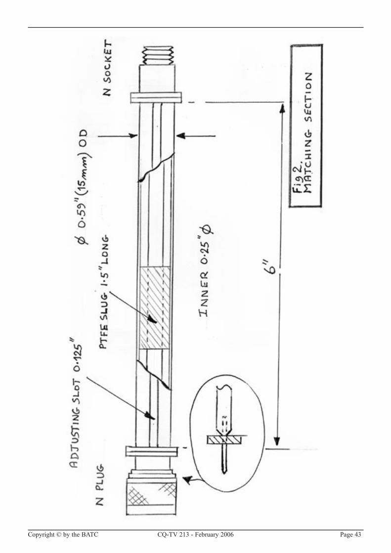
Copyright © by the BATC CQ-TV �13 - February �006 Page 43

Page 44 CQ-TV �13 - February �006 Copyright © by the BATC
getting hot, but at our power levels it is of little concern.
ConstructionThe general arrangement of the antenna can be seen from drawing 4. Ted had made it using aluminium tube, but this presented a problem of connecting the balun to the sides of the slot in a way that it would be reliable for a long time. I would have liked to have used copper tube and to silver solder the connections, a method that should last well, but unfortunately no tube of suitable size could be obtained. I eventually resorted to fitting copper strips to the sides of the slot at the feed points and attaching them with 3 screws each. These have tabs, which are bent inwards to connect with the balun. The arrangement can be seen in drawing 1. I would also have liked to have zinc plated the copper parts as zinc is near to aluminium in the galvanic table and this would reduce the risk of corrosion. Unfortunately none of the plating shops in the district could offer zinc. The best I could do was to thoroughly cover the joints with a protective sealant to prevent the ingress of moisture.
G3JVL advocates making the 4:1impedance transforming balun by slotting the outer of the end of the semi rigid feeder. As I found this tricky I resorted to the use of the other loop type balun made out of semi rigid line. Details of this can also be seen in drawing 1.
The whole antenna is protected by a length of plastic drain pipe with a top cap. I checked the loss of this by putting a slice in the microwave oven. As it did not get hot it must have a fairly low loss.
The Post MortemWhen the old antenna was takendown, despite its long exposure to the elements, it was found to be in generally good condition. Before taking it apart I speculated as to what had failed and thought it most likely that the feeder had become detached from the slot. That is exactly what I found. Vibration, humidity and temperature cycling had taken their toll and the soldered joint had failed. One really must make a strong mechanical joint before soldering! PV is back in service and the old antenna, refurbished, is in store against any future need.
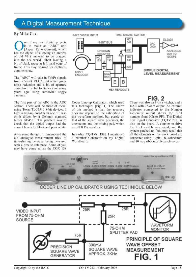
Copyright © by the BATC CQ-TV �13 - February �006 Page 45
By Mike Cox
One of my next digital projects is to make an “ARC” unit[Aspect Ratio Convert], which
has the object of allowing an archive of old VHS material to be draggedinto the16:9 world, albeit leaving a bit of blank space at left hand edge of frame. This may be used for captions, comments etc.
The“ARC”will take inYpbPrsignalsfrom a Vistek VEGA unit which gives noise reduction and a bit of aperture correction; useful for tapes shot many years ago using somewhat soggy cameras.
The first part of the ARC is the ADC section. There will be three of these, usingTexas TLC5540 8-bit devices. Ihave a lash-up board with one of these on it driven by a Gennum clamped buffer GB4551. The problem was to check that the digital output had the correct levels for black and peak white.
After some thought, I remembered the old analogue measurement trick of time-sharing the signal being measured with a precise reference. Some of you may have come across the COX 138
Coder Line-up Calibrator; which usedthis technique. [Fig. 1] The charm of this method is that the accuracy does not depend on the calibration of the waveform monitor, but purely on that of the square wave generator, the attenuators and the mixing pad, which are all 0.1% resistors.
In earlier CQ-TVs [199], I mentioned a Number Generator on my Digital WorkBoard.
There was also an 8-bit switcher, and a DAC with 75-ohm output. An external indicator connected to the Number Generator output shows the 8-bit number from 00h to FFh. The Digital Test Signal Generator [CQTV �01} is also on the board. A counter to drive the � x1 switch was wired, and the system patched up. You may recall that all the elements on the work board are connected using 10-pin IDC connectors and 10 way ribbon cable patch cords.
A Digital Measurement Technique

Page 46 CQ-TV �13 - February �006 Copyright © by the BATC
It was a bit noisy but it worked. All the elements were now together for a practical device to set up the ADCs.
Fig.� shows the block diagram of this unit.
Because the dc sits of the signals are under our control, a square wave [as in the 138 Calibrator] is not required. A single digital value from the number generator suffices.
Hunting around one of my boxes ofboards, I came across a prototype Number Generator board that carried two TexasHexadecimalreadouts[TIL311].There was room on the board for the switchmadeupoftwo74HC541s,anda DAC with 75-ohm output driver. This last used a DAC0800, which is a non-clocked DAC to simplify matters, rather than the clocked Philips TDA870� used on the work board. The absence of clock
means that the unit will run at any clock rateuptoaround18MHz,particularlyuseful when the ARC input sampling frequencywillbe10.125MHz.
The switching between the input 8-bit digital signal [from the ADC] and the Number Generator output is controlled by a simple oscillator running at around 6 kHz driving a spare section of a Dflip-flop.
TheDACdrivesanEL2020amplifier,and gives around 1 volt into 75 ohms for 00h to FFh excursion. A 3rd order Gaussian filter at the output helps remove glitches.
A simple +5 volt to –5-volt converter provides –ve supplies for the DAC and the output stage, with the unit operating from a single +5 volt supply.
Fig. 3 shows the board on the bench, the case alongside, and some ‘scope traces above showing the unit in action.
Fig. 4 gives the circuit of the complete unit.
It is relatively simple and uses industry standard parts. The shaft encoder drives the D flip-flop so as to provide up or down clock signals depending on the direction of rotation. The 8-bit counter ismadeup from2 ’HC193devices intandem.They drive theHex read-outsaswellasoneofthe‘HC541switches.
The decoding around the counter uses diodes rather than AND /OR logic chips as they were there, and take up less board space.
With the Editor’s blessing, I will tellyou more about the ARC unit when it is complete and working.

Copyright © by the BATC CQ-TV �13 - February �006 Page 47

Page 48 CQ-TV �13 - February �006 Copyright © by the BATC
The calibrator in action
By Graham Hankins G8EMX
I feel that the situation within ATV and the BATC has now reached such a state where something really
has to be expressed concerning several aspects within the club and amateur television. Again this year I have attended some rallies for the BATC and I still think it important to do this – fly the flag – show that we are still here. But my perception is one of fewer visitors, less traders, more empty tables at rallies, traders packing up earlier etc. Also the more tangible returns are definitely fewer - less new members, less renewals, often nil of either. But, more critically, there is very little I can offer any new enquirer anyway, other than BATC membership itself and sometimes a few back numbers and the CD. Go to the Remote Imaging Group table and you will find weather satellite receiving kits for sale to anyone who joins the RIG.
What can I say to any radio amateurwhowantstodabbleinATV?Andyes,
committee, I do mean ‘radio amateur’ because the hobby is not dead – ask any of the 40 plus ATV repeater groups. But I digress. There is only one ATV receiver currently being advertised, available only by mail order, similar with a transmitter. As for ATV antennas, Severnside has stopped advertising its simple yagis. TheWorthing / Solenttransmitter is long discontinued, Bob Platts has disappeared along with his Dove receiver. Only one �4cm ATV transmitter kit is available and that is not advertised, only by word-of-mouth.
I am therefore intending to draft some propositions for the General Meeting sometime in �006, along the following lines:
That the BATC should make available a basic �4cm ATV receiver, adequate in performance for local or repeater contacts.
That the BATC should make available a basic �4cm ATV transmitter, adequate for local or repeater contacts.
That the BATC should seek or provide a source of basic Yagi antennas of adequate performance for local or repeater contacts.
Each of the above to be available in small quantities from any BATC rally table, or by mail order from its Members Services.
I am sure there is sufficient expertise within the many ATV repeater groups to assist in these projects - after all, these members are designing and developing entire repeaters.
I am prepared to make these items into formal Agenda propositions to any coming General Meeting for discussion by the wider membership and committee. If any member wishes to suggest wording amendments or suggest further propositions, please contact me or any other of the BATC committee.
Feelings

Copyright © by the BATC CQ-TV �13 - February �006 Page 49
By Dicky Howett
Looking rather apprehensive in our photo, Paul Marshall and his ob van were featured
recently on Anglia Television. This was in conjunction with a Marconi Studio veterans reunion evening at their Social Club in Chelmsford. Also on the day, (Friday 14th October) itwas announced to much consternation that the erstwhile Marconi factory in New Street, Chelmsford is to close for good. However, Paul and chums puton a splendid display of old Marconi cameras and at 6 o’clock gave a live exhibition of themselves.
Veteran Marconi

Page 50 CQ-TV �13 - February �006 Copyright © by the BATC
CQ-TV is published quarterly in February, May, August and November each year. The
deadlines for each issue are as follows: -
Please send your contributions in as soon as you can prior to this date.
Willallprospectivecontributorspleasebesure to read the ‘Notice to Contributors’ on page 3 so that you understand the implications of submitting an article for publication.
If you have pictures that you want including in your article, then please send them, in the highest possible quality, as separate files.
Commercial adverts should be sent to Trevor Brown, the advertising manager, at 14 Stairfoot Close, Adel, Leeds, LS168JR. Tel: 01132670115. Email: [email protected]. Members’ sales and wants should be sent to the Editor. Email: [email protected]
February 30th DecemberMay 30th March
August 30th JuneNovember 30th September.
Deadlines
Amateur Television Quarterly .............................................................................35BATC Publications ..............................................................................................11BlackBoxCameraCompanyLimited ....................................................................�CQ-TV Commercial Advertising Rates ..............................................................50BATC DVD .........................................................................................................5�HSPublications ...................................................................................................50Members Services ...............................................................................................11
CQ-TV Commercial
Advertising Rates
Size Mono Colour
Quarter page £50 £75
Halfpage £100 £150
Full page £150 £�00
If you would like to advertise in CQ-TV, then please contact our advertising manager, Trevor Brown,
14StairfootClose,Adel,Leeds,LS168JR,England.Telephone:+44(0)1132670115. Email: [email protected]
Index of Advertisers
HS Publications7 Epping Close, Derby, DE22 4HR.
Telephone: 01332 38 16 99Email: [email protected]
• DX-TV Converters
• VHF-UHF TV Aerials
• DX-TV Publications and Videos
• Amplifers - Filters - Hardware
• Technical Books
• BBC Test Card music CDs
• TV Clocks and Archive Publications
Send 3 First Class stamps for our latest catalogue Personal callers by prior arrangement only please

Copyright © by the BATC CQ-TV �13 - February �006 Page 51
Caption competition
Can you think of a caption for this picture? If you can, then send your entry to [email protected]. The winner will receive a Black Box caption generator
Close-up of Bar Display - see Circuit Notebook

Page 5� CQ-TV �13 - February �006 Copyright © by the BATC
We have produced a DVD containing electronic versions of CQ-TV and the CQ-TV articles index. Also included are electronic
versions of our three most recent handbooks, ‘Slow Scan Television Explained‛, ‘Amateur Television Handbook‛ and
‘An Introduction to Amateur Television‛.
The archive is constantly being updated as more of the old paper issues are converted to electronic format. Currently issues 1 to 134 and 161 to 211 are included along with a few odd ones.
This DVD is updated 4 times a year, to include the current issue of CQ-TV.
The DVD is playable in a standard (domestic) DVD player (and on a PC with a DVD player) and the data files will ‘auto-run‛ when the DVD is put into a PC.
The video section was prepared by Brian Kelly and contains videos from Bletchley Park 1999, one from
Shuttleworth 2002 and one from 2004. The cost for this DVD is £5.00 for current members and £10.00 for
non-members.
Note: This DVD is supplied on +R media only.
£5