pi swarm system - university of york · pi swarm system manual version 0.91 draft - api version 0.6...
TRANSCRIPT

PI SWARM SYSTEM Manual Version 0.91 Draft - API Version 0.6 - PCB 1.2 - February 2014
This document contains information about the hardware and software
for the Pi Swarm robotic platform.
Reference Manual

Pi Swarm Manual York Robotics Lab pg. 1
Pi Swarm System
For PCB Version 1.1 & 1.2 and API Version 0.5
12th February 2014
Contents Introduction .................................................................................................................................................................... 2
The Pololu 3-Pi Robot ..................................................................................................................................................... 2
The MBED LPC1768 Rapid Prototyping Board ................................................................................................................ 3
The Pi Swarm Extension Board ....................................................................................................................................... 4
PCB Versions ............................................................................................................................................................... 4
Hardware .................................................................................................................................................................... 4
Basic Design ............................................................................................................................................................ 5
MEMS Sensors ........................................................................................................................................................ 5
Infrared Proximity Sensors ...................................................................................................................................... 6
Temperature and Light Sensors .............................................................................................................................. 6
RF Transceiver ......................................................................................................................................................... 6
USB Header ............................................................................................................................................................. 6
ID Switch ................................................................................................................................................................. 7
Direction Switch ...................................................................................................................................................... 7
EEPROM .................................................................................................................................................................. 7
Outer RGB LEDs ...................................................................................................................................................... 7
Central RGB LED ...................................................................................................................................................... 7
3-Pi Sensors ............................................................................................................................................................ 8
3-Pi Actuators ......................................................................................................................................................... 8
Construction ............................................................................................................................................................... 8
Schematic ................................................................................................................................................................... 9
PCB Design .................................................................................................................................................................. 9
Components ............................................................................................................................................................. 10
Software ....................................................................................................................................................................... 11
Communications ....................................................................................................................................................... 12
Communications Hardware .................................................................................................................................. 12
Communications Software .................................................................................................................................... 12
Pi Swarm API ................................................................................................................................................................. 15

Pi Swarm Manual York Robotics Lab pg. 2
piswarm.cpp ............................................................................................................................................................. 15
Outer LED Functions ............................................................................................................................................. 15
Center LED Functions ............................................................................................................................................ 15
IR Sensor Functions ............................................................................................................................................... 15
MEMS Sensor Functions ....................................................................................................................................... 16
Other Sensor Functions ........................................................................................................................................ 17
Motor Functions .................................................................................................................................................. 17
Sound Functions ................................................................................................................................................... 17
Display Functions .................................................................................................................................................. 17
EEPROM Functions ............................................................................................................................................... 18
communication.cpp .................................................................................................................................................. 18
Data Request Functions ........................................................................................................................................ 18
Operational Notes ........................................................................................................................................................ 19
Power Consumption ................................................................................................................................................. 19
Introduction
The Pi Swarm System is an extension for the Pololu 3-Pi robot that enables the robot to feature as part of a fully
autonomous swarm. At the core of the system is an MBED LPC1768 rapid-prototyping microcontroller board, which
allows code to be easily created on any system with a USB-port and web-browser, without the need for any
dedicated software or drivers. The MBED connects to a PCB designed in-house at YRL (www.york.ac.uk/robot-lab)
that adds a number of sensors and actuators to augment those already present on the 3-Pi platform, allow for more
complex interactions between robots to take place.
This document describes both the hardware that makes up the Pi Swarm System, and the basic API and software
libraries that can be used in the MBED online compiler (and also exported for offline development using a variety of
C++ programming tool-chains and IDEs). This version of the document is specifically for versions 1.1 and 1.2 of the Pi
Swarm PCB and version 0.6 of the API and software libraries.
The Pololu 3-Pi Robot
The 3-Pi robot, manufactured by Pololu (www.pololu.com) is a circular mobile platform featuring two micro metal
gear motors, five IR reflectance sensors, an 8x2 character LCD display, a buzzer and three user pushbuttons. It retails
at around £80 and can be purchased at a number of UK-based robotics stores (such as www.active-robots.com), or
direct from Pololu themselves. It is powered by a set of 4 AAA batteries (high-capacity Ni-MH recommended).
The peripherals and actuators are all connected to a C-programmable ATmega328 microcontroller, which operates
at a 20MHz clock-speed and features 32KB of flash program memory, 2KB of RAM and 1KB of persistent EEPROM

Pi Swarm Manual York Robotics Lab pg. 3
memory. The platform can be programmed using the GNU C/C++ compiler and Atmel Studio can be used as a
development environment. However, for typical use with the Pi Swarm system, a generic firmware is used which
reacts to messages sent over a serial-bus from the MBED board to operate all core functions of the robot. For more
information on the 3-Pi, consult the User’s Guide, Quick Start Guide and Sample Projects available on the Pololu
website (http://www.pololu.com/product/975/resources).
Pololu 3-Pi Robot: Top View Pololu 3-Pi Robot: Bottom View
The MBED LPC1768 Rapid Prototyping Board
The mbed LPC1768 is a small PCB designed to allow rapid prototyping for general microcontroller applications. It is
based around the NXP1768, a 32-bit ARM® Cortex™-M3 microcontroller which operates at a 96MHz clock frequency
and includes 32KB RAM and at least 512KB FLASH memory (1MB on newer boards) which appears as a USB-FLASH
drive when connected to a computer. It is available to purchase from Farnell (uk.farnell.com) for roughly £40. It
features a lot of interfaces and busses, including built in Ethernet, USB (host- and device-), CAN, SPI, I2C, 6 channels
of ADC, 6 channels of PWM output, a DAC and up to 26 GPIO pins [certain pins are shared between interfaces so not
all will be available at one time]. Additionally on-board LEDs are connected to other GPIO pins on the
microcontroller.
One of the key differences between the MBED and other similar microcontroller based prototyping boards is the
availability of an online compiler at www.mbed.org. This compiler provides the toolchain and libraries necessary to
quickly create C++ programs which can be compiler and installed onto the mbed. The bootstrap loader on the mbed
board simply loads the most recent binary file that has been saved onto the FLASH memory upon reset, so the
process of uploading new code to an mbed board is simple:
1. Navigate to www.mbed.org on a web browser, log in (creating a new account if necessary), open the compiler, and create the code
2. Compile the code and download the compiled binary (.bin) 3. Connect the mbed board to the computer using a mini-USB – USB cable and save the .bin file in the flash
drive folder 4. Press reset on the mbed board – the new code should now run
Pi Swarm Manual York Robotics Lab pg. 4
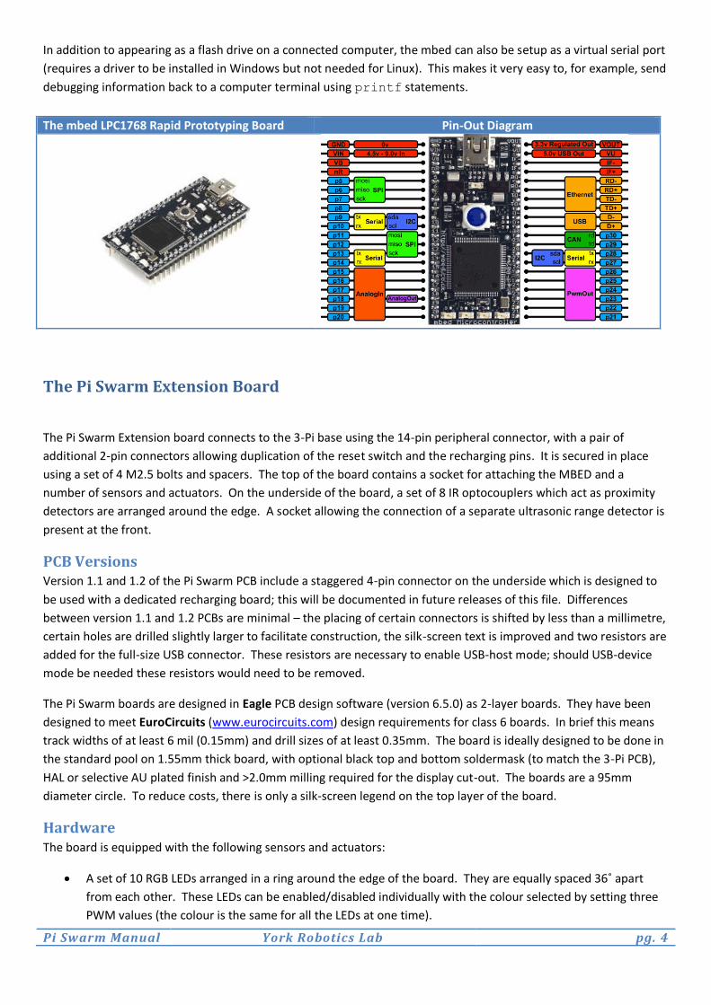
In addition to appearing as a flash drive on a connected computer, the mbed can also be setup as a virtual serial port
(requires a driver to be installed in Windows but not needed for Linux). This makes it very easy to, for example, send
debugging information back to a computer terminal using printf statements.
The mbed LPC1768 Rapid Prototyping Board Pin-Out Diagram
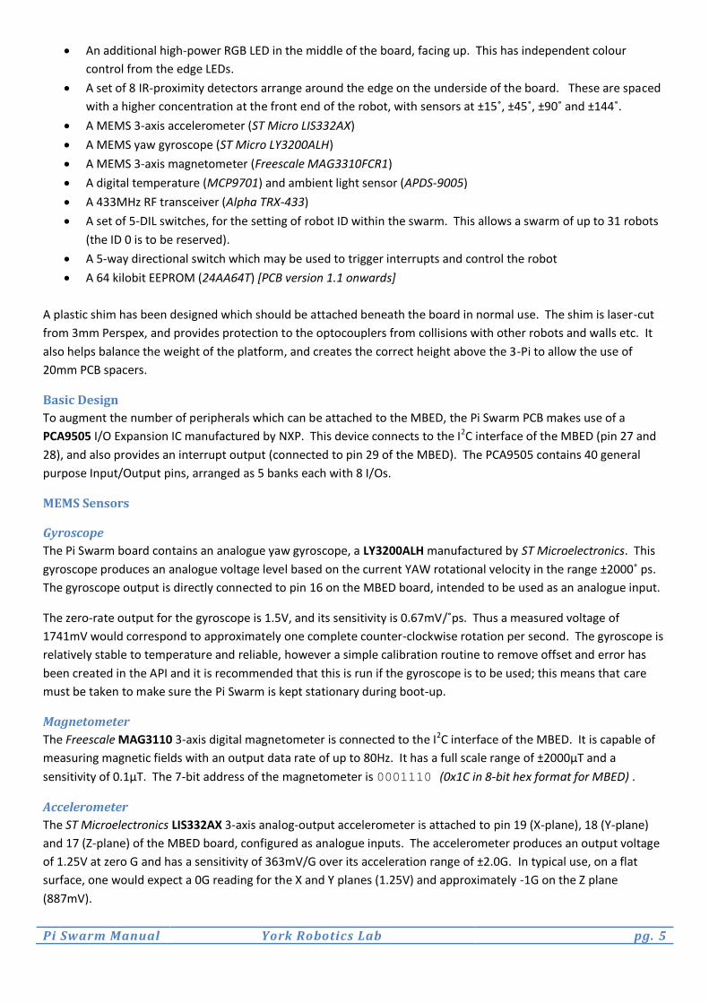
The Pi Swarm Extension Board
The Pi Swarm Extension board connects to the 3-Pi base using the 14-pin peripheral connector, with a pair of
additional 2-pin connectors allowing duplication of the reset switch and the recharging pins. It is secured in place
using a set of 4 M2.5 bolts and spacers. The top of the board contains a socket for attaching the MBED and a
number of sensors and actuators. On the underside of the board, a set of 8 IR optocouplers which act as proximity
detectors are arranged around the edge. A socket allowing the connection of a separate ultrasonic range detector is
present at the front.
PCB Versions Version 1.1 and 1.2 of the Pi Swarm PCB include a staggered 4-pin connector on the underside which is designed to
be used with a dedicated recharging board; this will be documented in future releases of this file. Differences
between version 1.1 and 1.2 PCBs are minimal – the placing of certain connectors is shifted by less than a millimetre,
certain holes are drilled slightly larger to facilitate construction, the silk-screen text is improved and two resistors are
added for the full-size USB connector. These resistors are necessary to enable USB-host mode; should USB-device
mode be needed these resistors would need to be removed.
The Pi Swarm boards are designed in Eagle PCB design software (version 6.5.0) as 2-layer boards. They have been
designed to meet EuroCircuits (www.eurocircuits.com) design requirements for class 6 boards. In brief this means
track widths of at least 6 mil (0.15mm) and drill sizes of at least 0.35mm. The board is ideally designed to be done in
the standard pool on 1.55mm thick board, with optional black top and bottom soldermask (to match the 3-Pi PCB),
HAL or selective AU plated finish and >2.0mm milling required for the display cut-out. The boards are a 95mm
diameter circle. To reduce costs, there is only a silk-screen legend on the top layer of the board.
Hardware The board is equipped with the following sensors and actuators:
A set of 10 RGB LEDs arranged in a ring around the edge of the board. They are equally spaced 36˚ apart
from each other. These LEDs can be enabled/disabled individually with the colour selected by setting three
PWM values (the colour is the same for all the LEDs at one time).
Pi Swarm Manual York Robotics Lab pg. 5
An additional high-power RGB LED in the middle of the board, facing up. This has independent colour
control from the edge LEDs.
A set of 8 IR-proximity detectors arrange around the edge on the underside of the board. These are spaced
with a higher concentration at the front end of the robot, with sensors at ±15˚, ±45˚, ±90˚ and ±144˚.
A MEMS 3-axis accelerometer (ST Micro LIS332AX)
A MEMS yaw gyroscope (ST Micro LY3200ALH)
A MEMS 3-axis magnetometer (Freescale MAG3310FCR1)
A digital temperature (MCP9701) and ambient light sensor (APDS-9005)
A 433MHz RF transceiver (Alpha TRX-433)
A set of 5-DIL switches, for the setting of robot ID within the swarm. This allows a swarm of up to 31 robots
(the ID 0 is to be reserved).
A 5-way directional switch which may be used to trigger interrupts and control the robot
A 64 kilobit EEPROM (24AA64T) [PCB version 1.1 onwards]
A plastic shim has been designed which should be attached beneath the board in normal use. The shim is laser-cut
from 3mm Perspex, and provides protection to the optocouplers from collisions with other robots and walls etc. It
also helps balance the weight of the platform, and creates the correct height above the 3-Pi to allow the use of
20mm PCB spacers.
Basic Design
To augment the number of peripherals which can be attached to the MBED, the Pi Swarm PCB makes use of a
PCA9505 I/O Expansion IC manufactured by NXP. This device connects to the I2C interface of the MBED (pin 27 and
28), and also provides an interrupt output (connected to pin 29 of the MBED). The PCA9505 contains 40 general
purpose Input/Output pins, arranged as 5 banks each with 8 I/Os.
MEMS Sensors
Gyroscope
The Pi Swarm board contains an analogue yaw gyroscope, a LY3200ALH manufactured by ST Microelectronics. This
gyroscope produces an analogue voltage level based on the current YAW rotational velocity in the range ±2000˚ ps.
The gyroscope output is directly connected to pin 16 on the MBED board, intended to be used as an analogue input.
The zero-rate output for the gyroscope is 1.5V, and its sensitivity is 0.67mV/˚ps. Thus a measured voltage of
1741mV would correspond to approximately one complete counter-clockwise rotation per second. The gyroscope is
relatively stable to temperature and reliable, however a simple calibration routine to remove offset and error has
been created in the API and it is recommended that this is run if the gyroscope is to be used; this means that care
must be taken to make sure the Pi Swarm is kept stationary during boot-up.
Magnetometer
The Freescale MAG3110 3-axis digital magnetometer is connected to the I2C interface of the MBED. It is capable of
measuring magnetic fields with an output data rate of up to 80Hz. It has a full scale range of ±2000µT and a
sensitivity of 0.1µT. The 7-bit address of the magnetometer is 0001110 (0x1C in 8-bit hex format for MBED) .
Accelerometer
The ST Microelectronics LIS332AX 3-axis analog-output accelerometer is attached to pin 19 (X-plane), 18 (Y-plane)
and 17 (Z-plane) of the MBED board, configured as analogue inputs. The accelerometer produces an output voltage
of 1.25V at zero G and has a sensitivity of 363mV/G over its acceleration range of ±2.0G. In typical use, on a flat
surface, one would expect a 0G reading for the X and Y planes (1.25V) and approximately -1G on the Z plane
(887mV).

Pi Swarm Manual York Robotics Lab pg. 6
Infrared Proximity Sensors
The Pi Swarm robot contains a set of 8 transistor driven reflective optical sensors around the edge of the board on
the underside. The optical component is a TCRT1000 manufactured by Vishay Semiconductor, which combines a
phototransistor and infrared emitter in a leaded package which blocks visible light. The phototransistors all feed into
an Analog Devices AD7997 8-channel, 10-bit analogue to digital converter, which is connected to the I2C interface of
the MBED (pin 27 and 28). The 7-bit address of the ADC is 0100011 (0x86 in 8-bit hex format for MBED) .
Each of the optocouplers also contains a 950nm infrared emitter. These are driven by a dedicated power supply
stage, which draws directly from the battery supply on the 3-Pi (to increase the current availability). The emitters
are enabled in sets of 4 – those facing forwards form set 1, and those facing to the side and backwards form set 2.
Set 1 is connected to GPIO Pin 12 of the MBED, and set 2 to pin 13. A logic high value will enable the emitters. It is
intended that the emitters are only enabled for short pulses last at most a few milliseconds at a time, as they draw
significant current (approximately 50mA per emitter). To reduce idle power consumption it is possible to turn the
power supply stage for the emitters into a sleep state; its enable pin is connected to IO2/6 PCA9505 I/O Expansion
IC.
Temperature and Light Sensors
Two other analogue sensors are placed close to the MBED on the Pi Swarm board. The temperature sensor, a
Microchip MCP9701T, is a linear active analog thermistor. This provides an output of 400mV at 0˚C and ±19.5mV
from this value for each ˚C difference, within the operating limits. The sensor is connected to AnalogIn pin 20 of the
MBED.
An ambient light sensor, the Avago APDS-9005, faces upwards on the Pi Swarm PCB. It can be found approximately
5mm below pin 21 of the MBED, between the RF board, aerial and USB expansion connector. This is connected to
AnalogIn pin 15 of the MBED, and provides a voltage proportional to the lux of light hitting the sensor. The sensor
produces 1V, close to its peak value, at approximately 1000 Lux of light.
RF Transceiver
The primary system for communication between Pi Swarm robots and remotely to a computer terminal is using a
433MHz FM transceiver system, based on the low cost Alpha-TRX433S module by RF Solutions. The transceiver
module connects to the MBED using the SPI interface and provides up to 115.2kbps data rate. A chip antenna is
mounted on the PCB just below the transceiver module, which provides a typical range of several meters at the
higher data rates and substantially further still if data rates are lowered.
The transceiver module itself supports the sending of simple short-word packets. To enhance usability, the software
API includes a simple communications stack which implements basic error-checking using CRC codes, and a simple
instruction protocol, allowing various control messages to be sent between devices. The protocol includes the ability
to broadcast messages (similar to UDP) to all listening robots, or to target individual device and form a reliable,
acknowledged link (similar to TCP/IP, although much more basic in scope).
USB Header
A USB type-A socket is positioned below the MBED board on the Pi Swarm PCB. The basic API does not include any
support for USB devices, although a number of such libraries have already been written by others for use with the
MBED, including support for USB BlueTooth dongles, Human-Interface Devices [keyboards, mice and joysticks etc]
and flash-memory drives. It is likely that a BlueTooth dongle could be used to provide an additional communication
network between robot-robot and robot-computer, although BlueTooth does have limits on the number of
supported connections so may not be suitable for larger swarms. In might in principle be possible to utilise an
802.11 Wi-Fi USB dongle, although it is likely that the processing and memory overhead needed to support such a
system might be beyond the practical capability of the MBED.

Pi Swarm Manual York Robotics Lab pg. 7
ID Switch
A 5-position DIL switch is positioned just above the display window, which allows each robot in the swarm to be
assigned its own unique ID. Whilst there are 32 different possible combinations, it is recommended that 0 is not
used, as this is utilised by the communications stack as the broadcast-to-all ID and as the ID for the radio modem. As
a result it is possible to create swarms up to 31 robots in size. In principle this could be expanded further by, for
example, recording more significant bits in the on-board EEPROM, effectively allowing multiple sub-swarms of up to
31 robots each.
The ID switch is connected to pins IO2/1 to IO2/5 of the PCA9505 I/O Expansion IC, which communicates with the
MBED using the I2C interface. In the standard API these pins are not set to trigger an interrupt, instead they are read
during the startup phase of the software and store the ID value in a local variable.
Direction Switch
To the right of the display window is a 5-direction push button switch. The direction switches are connected to pins
IO1/2 to IO1/6 of the PCA9505 I/O Expansion IC. In the standard API these pins are set to trigger an interrupt,
which is connected to pin 29 to of the MBED. A small delay is associated to provide a simple software debounce of
the switch and prevent multiple routines being triggered. An alternative solution to reading the switch would be to
periodically poll the switch IO pins on the expansion IC or pin 29 on the MBED.
EEPROM
A 64-kilobit (8KB) EEPROM, the Microchip Technology 24AA64, is connected to the I2C interface of the MBED. It is
accessed using the 7-bit address 1010000 (0xA0 in 8-bit hex format for MBED). The EEPROM chip itself is sorted
into 32-byte pages, and can be instructed to do either byte write or page write operations; it should be noted that a
page write operation is restricted to a single physical page and that if it extends beyond the 32nd byte of a page the
data will wrap over to overwrite the start of the page. An API routine abstracts this limitation and allows longer
messages to be written regardless of where in a page they begin. It is important to remember that any write
operation to EEPROM is relatively slow. The API follows the datasheet guidelines and adds a 5ms delay after any
write operation (byte- or page-) which ensures that the data is correctly written; be aware that writing several
hundreds of bytes will take several milliseconds. It is intended that in future API release a part of the EEPROM
(possibly the first 4KB) will be reserved for system use, for storing things such as calibration data for individual
robots, and the remainder will be “user area”. The API will abstract this information away but it does mean that the
entire 8KB area may not be available to the controller code.
Outer RGB LEDs
The edge of the Pi Swarm PCB contains ten very small right-angled RGB LEDs, evenly spaced at 36˚ intervals and
numbered from 0-91 clockwise around the PiSwarm starting from the 036˚ position. Each LED has its own enable pin
connected to a GPIO pin on the PCA9505 expansion IC, that lets the outer LEDs be individually enabled or disabled.
All ten LEDs share three connections to the PWM outputs on the MBED which assigns the colour of the LED: one
output controls the red value, one green and one blue. Note that this arrangement means that the enabled outer
LEDs must all be the same colour at one instance in time; the effect of having multiple colours at once on different
LEDs could be implemented by rapidly enabling and disabling the LEDs and changing the colours if needed.
Central RGB LED
The central user LED is an upwards-facing, high intensity RGB LED that sits right in the center of the Pi Swarm PCB.
This is directly connected to the other three PWM outputs on the MBED and is thus totally independent from the
outer LEDs.
1 Note that these are numbered 0-9 in the API but 1-10 on the PCB silk-screen

Pi Swarm Manual York Robotics Lab pg. 8
3-Pi Sensors
The 3-Pi itself contains a set of 5 infrared proximity sensors on the underside of the front of the PCB, which are
intended primarily to allow line following. These raw value from these sensors ranges from 0 to 2000. A relative
value of a preset variable resistor on the underside of the PCB can be read, which may be of use in setting offsets for
slight variation between 3-Pi bases. Note that there are actually 2 variable resistors; the one centrally between the
wheels is the user preset, the one closer to the left wheel controls the contrast of the 7x2 display.
3-Pi Actuators
The primary actuators on the 3-Pi are the pair a motors which drive the platform. At the lowest level, a floating
point value ranging from -1.0 to 1.0 is sent to the 3-Pi microcontroller to set the relative motor output. Other
actuators on the 3-Pi include the 7x2 LCD display, which can be written to using standard C printf commands, and
two user LEDs on the bottom of the Pi Swarm. There is a buzzer which can convert a ASCII string into conventional
notes; examples and a description about using the buzzer can be found in piswarm.h.
Construction The Pi Swarm PCB contains three sets of connectors which link it to the 3-Pi base. The main connector is a 2x7 pin,
0.1” pitch connector, that contains the serial link from the MBED to the ATmega microcontroller on the 3-Pi. This
connector also contains the power supply and ground lines. Two other 2-pin connectors link to the charge
connector and to the power switch, allowing these to be routed up to the Pi Swarm board. Spacers are used to hold
to Pi Swarm board firmly in place.
As supplied a 3-Pi base does not contain sockets for these connectors. A suitable 2x7 socket [similar to that soldered
on the base to connect the display]and a pair of 2x1 sockets need to be soldered to the 3-Pi base. The Pi Swarm is
drilled to accept M2.5 threads; the 3-Pi as supplied has M2 holes. As M2.5 hardware is stronger and far easier to
source, a minor modification to the holes on the 3-Pi base to enlarge them to M2.5 is recommended – this can be
done with a round needle file or, with care, a suitable drill.
A pair of plastic shims have been designed to be sandwiched below and above the Pi Swarm PCB, which give
protection to the IR sensors and the surface components. These are designed to be laser-cut on 3mm Perspex.
Extreme care should be taken when mounting the Pi Swarm board to the 3-Pi as it is easy to mis-mate the
connectors, which can in certain combinations cause short circuits which have the potential to damage both the 3-Pi
and the Pi Swarm board, regardless of power being turned on.
Top Plastic Shim Bottom Plastic Shim

Pi Swarm Manual York Robotics Lab pg. 9
Schematic
PCB Design
Silk Screen Top Layer Bottom Layer

Pi Swarm Manual York Robotics Lab pg. 10
Components Parts-list for Pi Swarm Extension Board Version 1.2
Parts Farnell Quantity Unit Price Total Price Value Manufacturer
3PI_HEADER 9689605 1 £0.98 £0.98 1241050-7 TE Connectivity
ACCEL 1838527 1 £1.78 £1.78 LIS332AX STMicro
ADC1 1078305 1 £4.61 £4.61 AD7997BRUZ-1 Analog Devices
ALPHA433 1718689 1 £4.97 £4.97 ALPHA-TRX433S RF Solutions
ANTENNA 2148530 1 £1.24 £1.24 ANTENNA Johanson Technology
C1,C4,C7,C8 1759037 4 £0.01 £0.04 100n Multicomp
C2,C15 2309028 2 £0.16 £0.32 10u TDK
C3 1759399 1 £0.01 £0.01 1u Multicomp
C5 1759396 1 £0.02 £0.02 470n Multicomp
C6 1759003 1 £0.01 £0.01 10n Multicomp
C9,C11 1658211 2 £0.35 £0.70 1u AVX
C10,C12 1759246 2 £0.02 £0.04 10n Multicomp
C13,C14 1754181 1 £0.15 £0.15 4.7u Vishay
CENTRE_LED 1855543 1 £0.62 £0.62 CLP6C-FKG Cree
CHG_IN,POWER_CON 1022245 2 £0.10 £0.20 2-PIN-CONNECTOR Harwin
CHG_OUT 1841369 1 £0.41 £0.41 2-PIN-CONNECTOR Wurth
EEPROM 2101260 1 £0.56 £0.56 24AA64T-I/OT IC 64KB Microchip
GPIO_CON 1756949 1 £1.53 £1.53 87832-1620 Molex
GYRO 1838547 1 £5.98 £5.98 LY3200ALH STMicro
I2C_CONN 9492437 1 £0.13 £0.13 B4B-PH-K-S JST
IO1 2212087 1 £2.54 £2.54 PCA9505DGG NXP
IR1-IR8 1470064 8 £0.76 £6.08 TCRT1000 Vishay
LED1-LED10 2335788 10 £0.39 £3.90 KPFA-3010RGBC-11 Kingbright
LIGHTSENSOR 1548110 1 £0.65 £0.65 APDS-9005 Avago
MAGNETO 2080492 1 £1.13 £1.13 MAG3310FCR1 Freescale
MBED-CON 1593469 2 £1.17 £2.34 2212S-20SG-85 Multicomp
N1-N8 9102710 8 £0.26 £2.08 IRLML2402PBF International Rectifier
NAND1-NAND10 1607738 10 £0.13 £1.30 74LCX00MTC Fairchild
R1 9238379 1 £0.01 £0.01 120 Yageo
R2,R3 2331705 2 £0.01 £0.02 33 TE Connectivity
R4-R13 1738888 10 £0.03 £0.30 50 Vishay
R14,15,19,22,25,28,31,34,37,40 2073350 10 £0.01 £0.10 100K Multicomp
R16,17,20,23,26,29,32,35,38 2073356 9 £0.01 £0.09 10k Multicomp
R18,21,24,27,30,33,36,39,41 2331703 8 £0.01 £0.08 22 TE
R41 1652868 1 £0.05 £0.05 2.2K Vishay
REG1,REG2 1469141 2 £0.71 £1.42 LP2992IM5-3.3 Texas Instruments
SONAR_CON 2084263 1 £0.79 £0.79 BG300-04-A-L-A Global
SWITCH1 1703878 1 £0.22 £0.22 FSMSM TE Connectivity
SWITCH2 1316988 1 £0.60 £0.60 MCTT5-V Multicomp
SWITCH3 1524009 1 £0.52 £0.52 MCEMR-05-T Multicomp
TEMP 1084622 1 £0.24 £0.24 MCP9701T-E/LT Microchip
USB_CONNECTOR 1654064 1 £0.80 £0.80 1734366-1 TE Connectivity

Pi Swarm Manual York Robotics Lab pg. 11
Using the Pi Swarm The power switch, located on the edge left of the display, is used to turn on and turn off the Pi Swarm. When no
MBED board is attached, this will power up the default firmware on the 3-Pi base, which will load the 3-Pi demo/test
code after approximately 5 seconds. This demo and test code can be used to check that the 3-Pi is working properly,
test the motors, monitor the battery level and check the line-following sensors. None of the hardware features on
the Pi Swarm expansion board can be tested with this software. To navigate between functions the user-buttons on
the 3-Pi (and not the Pi Swarm expansion) must be used.
Charging
The charging connector, located on the left-hand edge next to the MBED, allows the batteries to be recharged
without having to remove them. To do this, a battery charger specifically designed to charge 4 external Ni-Mh AAA
cells must be used, and must be fitted with the suitable connector (a 0.1” pitch, 2 pin, locking plug, such as Farnell
code 1841370). A high-quality, fully programmable battery charger such as a Tenergy TB6AC is ideal for this.
It is strongly recommended that the Pi Swarm is switch off during charging. Depending on the batteries used, it is
recommended that an absolute maximum charge rate of 0.5C is used, that a timer is used to ensure that the charger
is switched off after 2 hours (or adjusted time based on charge rate). Alternatively, most Ni-Mh will happily accept a
trickle charging at 0.05C or less indefinitely without damage; check the datasheet of the batteries used to see if this
is the case.
Pi Swarm Manual York Robotics Lab pg. 12
Software The Pi Swarm robot has an MBED C++ library that provides the API routines and internal functions to allow all of the
main Pi Swarm (and 3-Pi) sensors and actuators to be controlled. The user functions from the API itself are described
in detail in the following section. The Pi Swarm Library comprises 6 key files: piswarm.cpp,
communications.cpp and alpha433.cpp along with their respective header files. The main API functions
can be found in piswarm.cpp with additional user functions related to RF transceiver communication stack in
communications.cpp.
Communications This section describes the setup and use of the Alpha 433 FM transceiver on the Pi Swarm board and the use of the
simple message handling and communications stack written for use with the transceiver. Other communications
interfaces, such as the use of BlueTooth dongles, Ethernet or IR communication are all potentially possible but
beyond the scope of this document; www.mbed.org would be a good starting point for research into possible
options here.
In the Pi Swarm API there two methods of handling the RF transceiver. For complete flexibility, the user can use
methods which simply use the transceiver as a communication channel; the user can write and receive string
messages from this channel and handle them as they wish. However, to improve reusability and compatability
between code, it is recommended to use the simple communication stack that has been implemented. The stack
also provides a library of 16 commands and 16 information requests that can be automatically handled by the robot
without requiring additional code to be written.
Communications Hardware
The Alpha RF transceiver is a low-cost standalone module for communication on the 433MHz FM band. The 433MHz
band allows low-power, license free communication; it is often used for applications such as garage door openers
and remote car keys. It is far removed from modern wireless communication systems such as 802.11x and
BlueTooth, but is suitable for allowing short messages (a few bytes) to be sent between connected devices at a
modest data rate. The transceiver is easily identifiable on the Pi Swarm PCB, being a standalone small green PCB to
the left of the MBED. Directly below the transceiver is the white chip-antenna for the RF system.
Communications Software
There are two pairs of files that handle communication in the Pi Swarm. “alpha433.cpp” and
“alpha433.h” are essentially the driver code for the transceiver. The low level functions required to initialise the
RF transceiver, set the transmission mode, and send and receive short packets of data are included in these files. To
reduce the likelihood of processing a corrupt packet, a parity checksum byte is appended to the end of every send
message; any packet received with an incorrect final byte is rejected.
“communications.cpp” and “communications.h” contain the simple communication stack written for use
with the Pi Swarms. The communication stack is enabled by defining the flag “USE_COMMUNICATION_STACK” as
1 in the code. When the communication stack is in use, any message received which passes the simple checksum
test is sent to the processRadioData() function in communications.cpp. Note that if the communication
stack is not being used, the message is instead sent to the processRawRFData()in the user’s code (normally in
main.cpp); the user would need to add code to handle the message appropriately here.
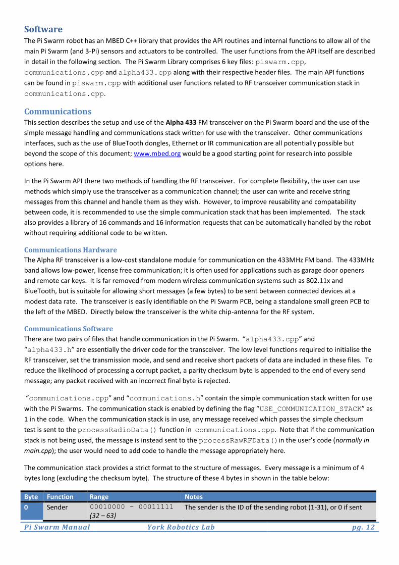
The communication stack provides a strict format to the structure of messages. Every message is a minimum of 4
bytes long (excluding the checksum byte). The structure of these 4 bytes in shown in the table below:
Byte Function Range Notes
0 Sender 00010000 – 00011111
(32 – 63) The sender is the ID of the sending robot (1-31), or 0 if sent

Pi Swarm Manual York Robotics Lab pg. 13
from a modem. 32 is added to the value. 1 Target 00010000 – 00011111
(32 – 63) The target is the ID of the intended recipient robot (1-31), or 0 if it is a broadcast message sent to all. 32 is added to the value.
2 Message ID 00000000 - 11111111
(0 – 255) The message ID is a 1-byte identifier set by the original sender of the command. A response to a command or request will share the original ID of that request.
3 Command See next table
When a message is received, the decodeMessage()function checks that it is valid message by ensuring a sender
and target bytes are within the correct range. It then determines if it is a target recipient of the message, by
checking if the target ID matches its own or the message is a broadcast message (target set to 0 +32). If the message
is not for this robot, it does no further processing.
Bit Definition Notes
7 is_response The is_response bit determines if the message is a response to a previous message (1) or is a new message (0).
6 request_response
or success The request_response bit determines if the sender is anticipating a response to the new message (1) or not (0). When the message is a response, this bit instead records whether the request or command issued in the prior message was successfully completed.
5 is_user The is_user flag determines if the message is user defined (1) or predefined by the communication stack (0).
4 is_command The is_command flag determines if the message is a command (1) or a request (0). Commands can be disabled in code, resulting in all command messages being rejected. Conversely requests are always handled.
3-0 Function The 4-bit (0-15) identifier for the required function. The communication stack provides a set of 16 basic commands and 16 requests for controlling the robots via RF.
There are a set of 15 predefined data request messages that can be sent using functions in
communications.cpp that can be found in the list below. Upon the receipt of a response to one of these
requests, the relevant data is stored in an array contained for all members of the swarm. A status flag changes state
to indicate that the request has been successfully answered.
Request Command Function Notes
0 0x80 send_rf_request_null 1 0x81 send_rf_request_left_motor_speed 2 0x82 send_rf_request_right_motor_speed 3 0x83 send_rf_request_button_state 4 0x84 send_rf_request_led_colour 5 0x85 send_rf_request_led_states 6 0x86 send_rf_request_battery 7 0x87 send_rf_request_light_sensor 8 0x88 send_rf_request_accelerometer 9 0x89 send_rf_request_gyroscope 10 0x8A send_rf_request_background_ir 11 0x8B send_rf_request_reflected_ir 12 0x8C send_rf_request_distance_ir 13 0x8D send_rf_request_line_following_ir 14 0x8E send_rf_request_uptime
Pi Swarm Manual York Robotics Lab pg. 14
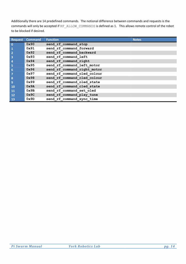
Additionally there are 14 predefined commands. The notional difference between commands and requests is the
commands will only be accepted if RF_ALLOW_COMMANDS is defined as 1. This allows remote control of the robot
to be blocked if desired.
Request Command Function Notes
0 0x90 send_rf_command_stop 1 0x91 send_rf_command_forward 2 0x92 send_rf_command_backward 3 0x93 send_rf_command_left 4 0x94 send_rf_command_right 5 0x95 send_rf_command_left_motor 6 0x96 send_rf_command_right_motor 7 0x97 send_rf_command_oled_colour 8 0x98 send_rf_command_cled_colour 9 0x99 send_rf_command_oled_state 10 0x9A send_rf_command_cled_state 11 0x9B send_rf_command_set_oled 12 0x9C send_rf_command_play_tune 13 0x9D send_rf_command_sync_time

Pi Swarm Manual York Robotics Lab pg. 15
Pi Swarm API
The following pages list all the main public functions from the core Pi Swarm API files (piswarm.cpp and
communications.cpp). There are a number of functions which are explicitly for setup, not intended for use in
user code, or legacy functions to maintain compatibility with m3-Pi code that are not included in the tables below.
piswarm.cpp
Outer LED Functions
Type Name Inputs Description int get_oled_colour (void) Returns the current setting for the outer LED colour.
Returned colour is stored as 24-bit positive integer (R<<16 + G<<8 + B). Used by communication stack.
char get_oled_state (char oled) Returns the current enable state an individual LED.
oled = LED to return enable state. Returns 0 for disabled, 1 for enabled
void set_oled_colour (char red, char green,
char blue) Set the colour of the outer LED. Values for red, green and blue range from 0 (off) to 255 (maximum).
void set_oled (char oled, char value) Set the state of an individual LED.
oled = LED to enable Value = 0 for disable, 1 for enable Use to change 1 LED without affecting others.
void set_oleds (char oled_x,...)
[x=0-9]
Sets the state of all 10 LEDs. oled_x = 0 for disable, 1 for enable Use to change all 10 LEDs at once
void turn_off_all_oleds (void) Sets all outer LEDs to disabled and turns off LED power supply.
void set_oled_brightness (char brightness) Set the brightness (total period of PWM output increases as brightness decreases). Ranges from 0 (minimum) to 255 (maximum)
void activate_oleds (void) Function responsible for sending updated outer LED enables to the GPIO expansion IC.
Called automatically after set_oleds but not
set_oled.
Center LED Functions
Type Name Inputs Description int get_cled_colour (void) Returns the current setting for the center LED colour.
Returned colour is stored as 24-bit positive integer (R<<16 + G<<8 + B). Used by communication stack.
char get_cled_state (void) Returns the current enable state for the center LED. Returns 0 for disabled, 1 for enabled
void set_cled_colour (char red, char green,
char blue) Set the colour of the center LED. Values for red, green and blue range from 0 (off) to 255 (maximum).
void enable_cled (char enable) Turn on or off the center LED.
enable=1 to turn on, 0 to turn off void set_cled_brightness (char brightness) Set the brightness (total period of PWM output
increases as brightness decreases). Ranges from 0 (minimum) to 255 (maximum)
IR Sensor Functions
Type Name Inputs Description float read_reflected_ir_distance (char index) Macro which estimates the distance to an
obstacle from one of the IR sensors, defined by
index (range 0-7). Function measures sensor value, then enables IR emitter and measures the value again. The value

Pi Swarm Manual York Robotics Lab pg. 16
is converted to an approximate distance in millimetres, or 100.0 if no obstacle found. Since API 0.6 it is recommended to use
store_reflected_distances() and get_reflected_ir_distance() unless only one or two IR distances are required, as this reduces the amount of time the IR emitters are active and improved efficiency.
float get_reflected_ir_distance (char index) Introduced in API 0.6 Returns the stored value of reflected distance saved on the last call of either
read_reflected_ir_distance() and store_reflected_distances()
unsigned
short
get_background_raw_ir_value (char index) Introduced in API 0.6 Returns the stored value of the non-illuminated sensor based on last call of store_background_raw_ir_values()
unsigned
short
get_illuminated_raw_ir_value (char index) Introduced in API 0.6 Returns the stored value of the illuminated sensor based on last call of store_illuminated_raw_ir_values()
void store_reflected_ir_distances (void) Introduced in API 0.6 Stores the reflected distances for all 8 IR sensors [calls
store_background_raw_ir_values then store_illuminated_raw_ir_values
then calculate_reflected_distance for all results]
void store_background_raw_ir_values (void) Introduced in API 0.6 Stores the raw ADC values for all 8 IR sensors without enabling IR emitters
void store_illuminated_raw_ir_values (void) Introduced in API 0.6 Stores the raw ADC values for all 8 IR sensors with a 500us emitter pulse
float calculate_reflected_distance (unsigned short
background_value,
unsigned short
illuminated_value)
Introduced in API 0.6 Converts a background and illuminated value into an approximate distance in mm (or 100.0 if no object detected) Used by
read_reflected_ir_distance() and store_reflected_ir_distances()
unsigned
short
read_illuminated_raw_ir_value (char index) Returns the illuminated raw sensor value for the
IR sensor defined by index (range 0-7). Turns the relevant emitter on for 500us before sampling.
unsigned
short
read_adc_value (char index) Returns the raw sensor value for the IR sensor
defined by index (range 0-7).
void enable_ldo_outputs (void) Function enables or disables the LDO voltage regulators which supply power to the outer LEDs and the IR photo emitters. In general this function is used internally, but it may be necessary to use when custom IR code is being written.
MEMS Sensor Functions
Type Name Inputs Description float read_gyro (void) Returns the yaw (clockwise) rotation in degrees-per-second reported
by the LY3200 gyroscope. float read_accelerometer_x (void) Returns the acceleration in the X plane reported by the LIS332
accelerometer. Returned value is in mg. float read_accelerometer_y (void) Returns the acceleration in the Y plane reported by the LIS332
Pi Swarm Manual York Robotics Lab pg. 17
accelerometer. Returned value is in mg. float read_accelerometer_z (void) Returns the acceleration in the Z plane reported by the LIS332
accelerometer. Returned value is in mg. char read_magnetometer (void) Sends message to the magnetometer to read new values.
Should be called before get_magnetometer_* when updated values are required
signed
short
get_magnetometer_x (void) Returns the raw value for the X-plane magnetic field stored on the
last call of read_magnetometer signed
short
get_magnetometer_y (void) Returns the raw value for the Y-plane magnetic field stored on the
last call of read_magnetometer signed
short
get_magnetometer_z (void) Returns the raw value for the Z-plane magnetic field stored on the
last call of read_magnetometer
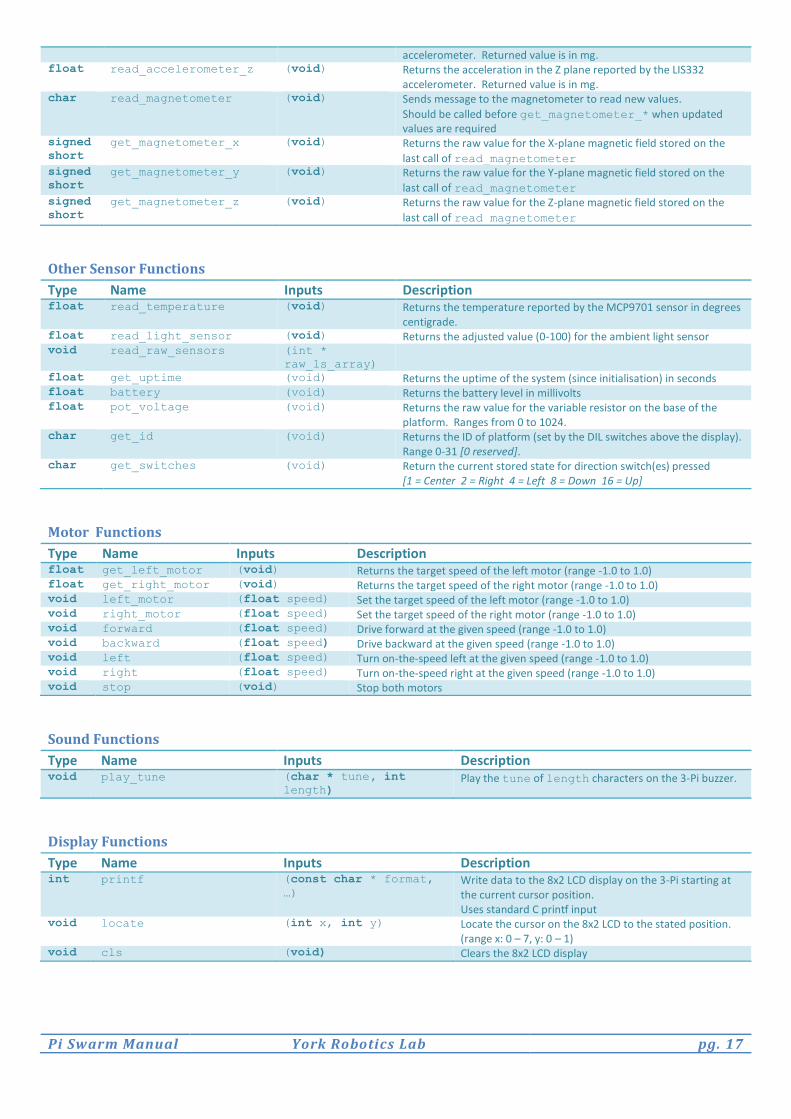
Other Sensor Functions
Type Name Inputs Description float read_temperature (void) Returns the temperature reported by the MCP9701 sensor in degrees
centigrade. float read_light_sensor (void) Returns the adjusted value (0-100) for the ambient light sensor void read_raw_sensors (int *
raw_ls_array)
float get_uptime (void) Returns the uptime of the system (since initialisation) in seconds float battery (void) Returns the battery level in millivolts float pot_voltage (void) Returns the raw value for the variable resistor on the base of the
platform. Ranges from 0 to 1024. char get_id (void) Returns the ID of platform (set by the DIL switches above the display).
Range 0-31 [0 reserved]. char get_switches (void) Return the current stored state for direction switch(es) pressed
[1 = Center 2 = Right 4 = Left 8 = Down 16 = Up]
Motor Functions
Type Name Inputs Description float get_left_motor (void) Returns the target speed of the left motor (range -1.0 to 1.0) float get_right_motor (void) Returns the target speed of the right motor (range -1.0 to 1.0) void left_motor (float speed) Set the target speed of the left motor (range -1.0 to 1.0) void right_motor (float speed) Set the target speed of the right motor (range -1.0 to 1.0) void forward (float speed) Drive forward at the given speed (range -1.0 to 1.0) void backward (float speed) Drive backward at the given speed (range -1.0 to 1.0) void left (float speed) Turn on-the-speed left at the given speed (range -1.0 to 1.0) void right (float speed) Turn on-the-speed right at the given speed (range -1.0 to 1.0) void stop (void) Stop both motors
Sound Functions
Type Name Inputs Description void play_tune (char * tune, int
length) Play the tune of length characters on the 3-Pi buzzer.
Display Functions
Type Name Inputs Description int printf (const char * format,
…)
Write data to the 8x2 LCD display on the 3-Pi starting at the current cursor position. Uses standard C printf input
void locate (int x, int y) Locate the cursor on the 8x2 LCD to the stated position. (range x: 0 – 7, y: 0 – 1)
void cls (void) Clears the 8x2 LCD display
Pi Swarm Manual York Robotics Lab pg. 18
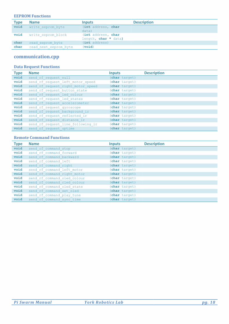
EEPROM Functions
Type Name Inputs Description void write_eeprom_byte (int address, char
data)
void write_eeprom_block (int address, char
length, char * data)
char read_eeprom_byte (int address) char read_next_eeprom_byte (void)
communication.cpp
Data Request Functions
Type Name Inputs Description void send_rf_request_null (char target) void send_rf_request_left_motor_speed (char target) void send_rf_request_right_motor_speed (char target) void send_rf_request_button_state (char target) void send_rf_request_led_colour (char target) void send_rf_request_led_states (char target) void send_rf_request_accelerometer (char target) void send_rf_request_gyroscope (char target) void send_rf_request_background_ir (char target) void send_rf_request_reflected_ir (char target) void send_rf_request_distance_ir (char target) void send_rf_request_line_following_ir (char target) void send_rf_request_uptime (char target)
Remote Command Functions
Type Name Inputs Description void send_rf_command_stop (char target) void send_rf_command_forward (char target) void send_rf_command_backward (char target) void send_rf_command_left (char target) void send_rf_command_right (char target) void send_rf_command_left_motor (char target) void send_rf_command_right_motor (char target) void send_rf_command_oled_colour (char target) void send_rf_command_cled_colour (char target) void send_rf_command_oled_state (char target) void send_rf_command_set_oled (char target) void send_rf_command_play_tune (char target) void send_rf_command_sync_time (char target)
Pi Swarm Manual York Robotics Lab pg. 19
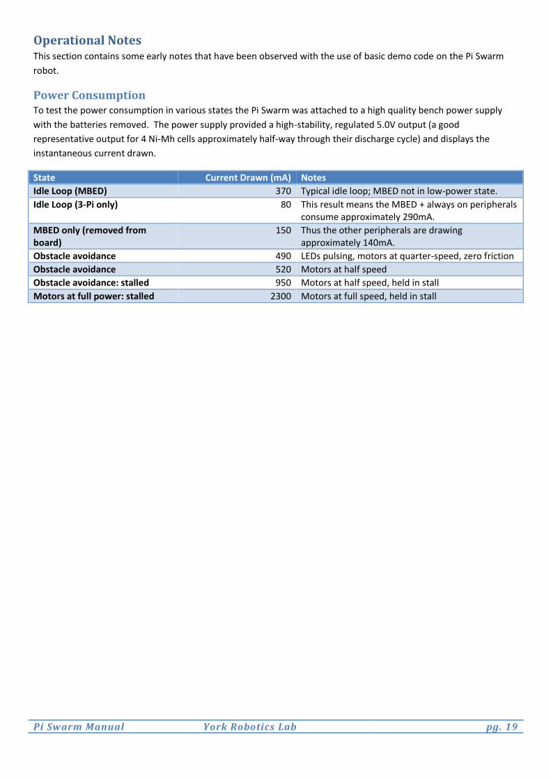
Operational Notes This section contains some early notes that have been observed with the use of basic demo code on the Pi Swarm
robot.
Power Consumption To test the power consumption in various states the Pi Swarm was attached to a high quality bench power supply
with the batteries removed. The power supply provided a high-stability, regulated 5.0V output (a good
representative output for 4 Ni-Mh cells approximately half-way through their discharge cycle) and displays the
instantaneous current drawn.
State Current Drawn (mA) Notes
Idle Loop (MBED) 370 Typical idle loop; MBED not in low-power state.
Idle Loop (3-Pi only) 80 This result means the MBED + always on peripherals consume approximately 290mA.
MBED only (removed from board)
150 Thus the other peripherals are drawing approximately 140mA.
Obstacle avoidance 490 LEDs pulsing, motors at quarter-speed, zero friction
Obstacle avoidance 520 Motors at half speed
Obstacle avoidance: stalled 950 Motors at half speed, held in stall
Motors at full power: stalled 2300 Motors at full speed, held in stall