pi separation incl higee
TRANSCRIPT
INTENSIFICATION O F SEPARATION PROCESSES
OBJECTIVES IN THIS CHAPTER
The principal objectives in this chapter are to discuss the several ways in which separation processes, ranging from distillation and evaporation though drying and crystallisation, can be intensified. There are process-specific methods such as liquid-liquid extraction, absorption and adsorption that must also be considered. The range of technologies is substantial, including high gravity fields (the HiGee distillation unit) and microwaves for drying. Techniques familiar to chemical engi- neers, including divided wall distillation columns (some say 'dividing wall') and new packing, are also covered. The aim is also to introduce the concepts so that they can be appreciated in the later applications chapters.
The chapter concentrates on 'active' intensification methods, such as rotation and electric fields, as these are the approaches that can produce radical changes in process plant design and performance, as with the spinning disc reactor described in Chapter 5.
6.1 INTRODUCTION
After reactions, separations are the most important unit operations within the chemical industry. Separations are also essential components of many other process industry sectors, in particular food and drink, paper and board, and textiles - where the removal of liquids in drying and the concentration of liquids (e.g. in soft drinks manufacture) are highly energy-intensive.
Distillation is the most significant separation processes within the process indus- tries. It is a major energy user in the chemicals sector where, together with drying and evaporation, it consumed the equivalent of a million tonnes of oil in the UK in 2004. Distillation columns are used in many operations, the main ones being:
Crude oil distillation Distillation of petroleum fractions
188 PROCESS INTENSIFICATION
LPG separation and gas processing General hydrocarbon separation Aromatic separation Waterlorganics separation Waterlinorganics separation.
A number of approaches can be adopted to reduce energy use in the columns, two major examples of which can involve process intensification. The first of these, improvements to the distillation column population to make the units more efficient rather than wholesale replacement by intensified alternative separation methods, is the most likely route in the short- to medium-term, covered briefly below. In the longer term, alternative plant or separation techniques are needed. Potentially the most important of these is HiGee.
There are a variety of other 'conventional7 separation methods used for evap- oration and drying processes and these can also benefit from the application of PI. Topics such as dewatering using centrifuges and the application of electrical enhancement methods to speed up drying are also discussed below.
6.2 DISTILLATION
6.2.1 Distillation - dividing wall columns
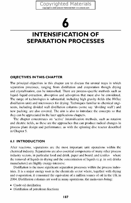
Dividing (or divided - the term varies) wall columns are a convenient way of putting two distillation columns into one shell, the 'wall' separating the two functions. Their use is applicable where three or more components require separating. Normally this needs two or more columns, with each column having its own reboiler and condenser - which is energy-inefficient, capital intensive and takes up a lot of space. Kaibel (2007) points out that there are two main types of dividing wall columns. The simpler type represents a column which has the dividing wall assem- bled either at the upper or lower end of the column (visible in Figure 6.1 in the sec- ond and third columns). The first applications on a production scale took place only in 2004, although the configuration was proposed in the 1930s. The more common type of dividing wall column is shown in the left side. The dividing wall is placed in the middle section of the column, above and below the feed and the side draw.
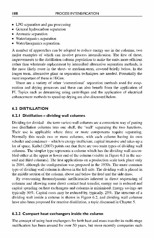
By overcoming thermodynamic inefficiencies inherent in direct sequencing of columns and allowing some direct contact heat transfer, energy use is reduced and capital spending on heat exchangers and columns is minimised. Energy savings are typically 30%. Capital costs may be reduced by, typically, 25%. The structure of a dividing wall inside a column is shown in Figure 6.2, and dividing wall columns have also been proposed for reactive distillation, a topic discussed in Chapter 5.
6.2.2 Compact heat exchangers inside the column
The concept of using heat exchangers for both heat and mass transfer in multi-stage rectification has been around for over 50 years, but more recently companies such
CHAPTER 6 INTENSIFICATION OF SEPARATION PROCESSES 189
Figure 6.1 Configurations of dividing wall distillation columns (Kaibel, 2007).
Figure 6.2 A view inside a dividing wall column (Kaibel, 2007).
190 PROCESS INTENSIFICATION
as Costain Oil, Gas and Process Ltd have used highly compact heat exchangers, particularly plate-fin units, for a variety of cryogenic duties including air separation and ethylene recovery. The reflux heat exchanger is functionally equivalent, stated Finn (1994), to the multi-stage rectification section of a distillation column. The advantages over conventional distillation are several, but two main benefits arise:
Small temperature differences exist between the condensing feed stream and the streams providing refrigeration. (Large temperature-driving forces lead to inef- ficiencies in conventional columns.) The CHE has a large number of partial condensation stages, so temperature and composition differences between vapour and liquid are small and separation takes place close to equilibrium conditions.
Some may argue the degree of intensification achieved using this technique, but the results are impressive; Finn quoted a greater than 99% recovery of the required olefins and much reduced downstream energy needs for fractionation. It is now appro- priate to examine in more detail the use of high gravity fields to aid separations - a technique that has been briefly introduced in earlier chapters - exemplified by HiGee.
6.2.3 HiGee
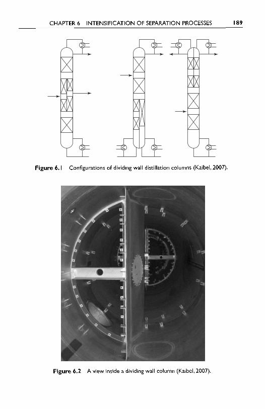
As its name implies the HiGee rotating packed-bed (Mallinson and Ramshaw, 1979; Ramshaw, 1993) comprises a rotating torus of packing which has a relatively high specific surface area compared to conventional column packing (Figure 6.3). Liquid is injected onto the inner cylindrical packing surface from a stationary set of nozzles and, after percolating through the packing, it leaves the rotor and enters the
Figure 6.3 The original HiGee rotating liquid contactor.
Liquid out
Reticulated foam torus
Vapour outLiquid in
Labyrinth seal
Vapour in
CHAPTER 6 INTENSIFICATION OF SEPARATION PROCESSES 19 1
machine case at the prevailing peripheral speed - typically 40-60 m/s. It then leaves by a suitable drainage point which must be designed so as to prevent liquid accu- mulation capable of interfering with the rotor operation. Vapour to be contacted enters the machine casing and is forced to flow radially inwards and leave via the rotor centre. As shown in Figure 6.3, a mechanical seal must be installed to block any vapour bypass flow around the rotor. The seal may be a lubricated face seal or the labyrinth type, the latter being preferred in view of the fairly high relative velocity at the seal contact point.
The packing employed must be able to withstand the body forces generated within the rotor, in order to maintain balanced conditions while having a specific area in the range 500-5000m2/m3 and a high voidage (>85%). Contenders for this duty are:
Reticulated metal foam Composite layers of gauze or expanded metal Wound layers of fibrous material.
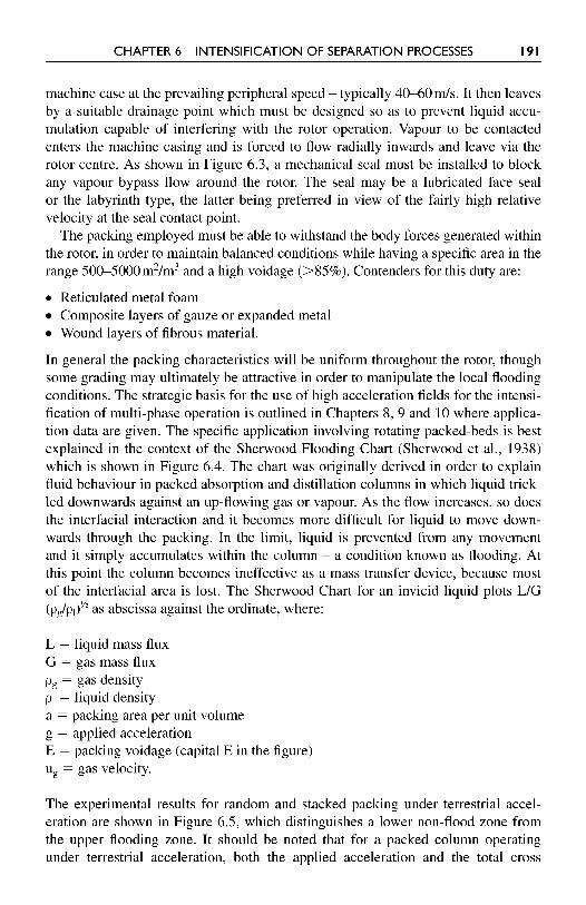
In general the packing characteristics will be uniform throughout the rotor, though some grading may ultimately be attractive in order to manipulate the local flooding conditions. The strategic basis for the use of high acceleration fields for the intensi- fication of multi-phase operation is outlined in Chapters 8, 9 and 10 where applica- tion data are given. The specific application involving rotating packed-beds is best explained in the context of the Sherwood Flooding Chart (Sherwood et al., 1938) which is shown in Figure 6.4. The chart was originally derived in order to explain fluid behaviour in packed absorption and distillation columns in which liquid trick- led downwards against an up-flowing gas or vapour. As the flow increases, so does the interfacial interaction and it becomes more difficult for liquid to move down- wards through the packing. In the limit, liquid is prevented from any movement and it simply accumulates within the column - a condition known as flooding. At this point the column becomes ineffective as a mass transfer device, because most of the interfacial area is lost. The Sherwood Chart for an invicid liquid plots LIG (pglp,)" as abscissa against the ordinate, where:
L = liquid mass flux G = gas mass flux p, = gas density pl = liquid density a = packing area per unit volume g = applied acceleration E = packing voidage (capital E in the figure) u, = gas velocity.
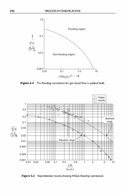
The experimental results for random and stacked packing under terrestrial accel- eration are shown in Figure 6.5, which distinguishes a lower non-flood zone from the upper flooding zone. It should be noted that for a packed column operating under terrestrial acceleration, both the applied acceleration and the total cross
192 PROCESS INTENSIFICATION
Figure 6.4 The flooding correlation for gas-liquid flow in packed beds.
Figure 6.5 Experimental results showing HiGee flooding correlation.
0.05 0.1 0.2 0.5
Higeeresults
1 2 5 100.010.001
0.002
0.005
0.01
0.02
0.05
0.1
0.2
0.5
1
0.02
��
rG rL
gE3
u g2a
Stackedrings
Random rings
L/G
( G/ L)
0.010.001
0.01
0.1
1.0
0.1
L/G( g/ L)1/2
1.0
Flooding region
Non-flooding region
10
u2 ga·
g
Lg
E3
CHAPTER 6 INTENSIFICATION OF SEPARATION PROCESSES 193
sectional area for fluid flow remain constant. Therefore, once the flooding condi- tion is reached, flooding occurs throughout the column and a sudden substantial increase in pressure drop is experienced.
The abscissa X of the Sherwood plot for a given process system is fixed by the process requirements which dictate the liquid and gas fluxes, L and G. Hence, for example, with a distillation column operating at total reflux L = G and, since pJp, - 1000, we have X - 0.03 and Y (flood) -0.2 for random packing. For a given system, whether under terrestrial or enhanced acceleration, this implies that X is constant. The centrifugal acceleration generated within a rotating bed is g = rw2 and it therefore increases towards the periphery. Noting that E~ for a high voidage packing will vary only over a limited range (say 0.5-0.75), a thousand fold increase in g implies that at the flooding limit either u, may be increased by a fac- tor -30 or the packing specific surface area can increase by a factor -1000. The first case allows both the gas and liquid flow to increase about thirty fold, since LIG is fixed, whereas the second case suggests that packing having a very high surface area can be used. This intuitively should lead to greatly improved mass transfer and reduced theoretical stage heights. In practice, both a and u, should be increased so as to create a roughly equi-axed toroidal packing.
In view of the largely radial nature of the gas and liquid flows within the pack- ing, the mass fluxes in the inner rotor zones are higher than those at the periphery. This, together with the radial variation of the centrifugal acceleration noted above, means that the tendency for the packing to flood is highest at the inner radius and least at the periphery. As a consequence, the flooding behaviour and the overall pressure drop characteristics of the packed rotor are very different from those of a stationary column, for which the flooding limit is reached simultaneously through- out the packing. The design of a HiGee contactor should therefore be based on an appropriate fraction of the flows at the inner flooding condition. In the absence of an abrupt increase in the overall pressure drop an experimental determination of the flooding condition for the rotor is quite difficult. However, it has been observed that an increased liquid agitation is detectable at the inner packing radius, coupled with a characteristic hissing noise as the flooding condition is approached. The results shown in Figure 6.5 were obtained on this basis and broadly correspond to those achieved with stacked packing in a column exposed to terrestrial acceleration. Fluid fluxes at flooding are of the order of tenfold higher than those in a column, with transfer unit heights of around 1.5 cm for gas film-limited systems and about 4cm for liquid film-limited systems.
The fluid flow behaviour within the rotor has been studied in some detail by Bums and Ramshaw (1996) who initially performed photographic investigations followed by hold-up and velocity measurements. Using diluted emulsion paint and black polyurethane sponge packing, it was shown that the liquid injected on the inner packing surface attained the local rotational speed after about 1 cm penetra- tion. Beyond this, at the lower rotor speeds, much of the liquid flow occurred in the form of discrete rivulets rather than being distributed uniformly over the pack- ing surface. As rotor speed increased, liquid tended to flow as 'flying droplets'
194 PROCESS INTENSIFICATION
across the packing voids in contrast to the previous rivulet/film flow. This probably accounts for the somewhat surprising observation that the best packing from a mass transfer point of view was not necessarily that having the greatest specific surface area. Coarse packing (e.g. with a surface area - 1000-2000 m2/m3) was generally better, presumably because 'flying droplets' were encouraged with their additional surface area. It will be recognised that coarse packing has the additional advantage of lower pressure drop.
The early development of the HiGee concept by ICI was based on a prototype unit for the ethanollpropanol distillation system. This used two rotors of Retimet (a Ni/Cr reticulated foam) having the dimensions:
ID 300 mm OD 800 mm Axial thickness 300 mm
After laborious improvements to the liquid distribution system in order to establish uniformity, over 20 theoretical distillation stages in the 25cm depth of packing was achieved. The presence of any flow shadows within the packing, such as could be caused by tie bolts, caused significant performance impairment. Clearly mal-distribu- tion is a major issue both for conventional packed columns and rotating packed beds.
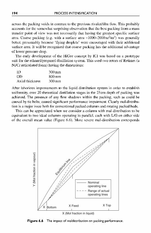
This can be appreciated when we consider a column with mal-distribution to be equivalent to two ideal columns operating in parallel, each with LIG on either side of the overall mean value (Figure 6.6). More severe mal-distribution corresponds
Figure 6.6 The impact of maldistribution on packing performance.
Bottom X Feed
X (Mol fraction in liquid)
Y (
Mol
frac
tion
in v
apou
r)
X Top
Nominaloperating line
Range of actualoperating lines
X
Equi
libriu
mlin
e
CHAPTER 6 INTENSIFICATION OF SEPARATION PROCESSES 195
to a bigger difference in the slope of the operating lines, i.e. LIG. For close-boiling mixtures the number of theoretical stages becomes particularly sensitive to a given change in LIG as a 'pinch' situation is created and approached. Thus, for a given mass transfer capacity, i.e. a given number of installed theoretical stages, the sepa- ration capacity of one or both columns is progressively compromised. In view of this only about 20 stages can be prudently expected within one rotor unless some redistribution technique can be applied. As a consequence, the separation of close boiling mixtures such as propanelpropylene requiring -200 theoretical stages can- not be performed in one rotor, however large. A feasible alternative is to install multiple packed-beds on one shaft and devise a suitable system for conducting liq- uid from the periphery of one to the interior of its successor along the shaft - and vice versa for the vapour flow.
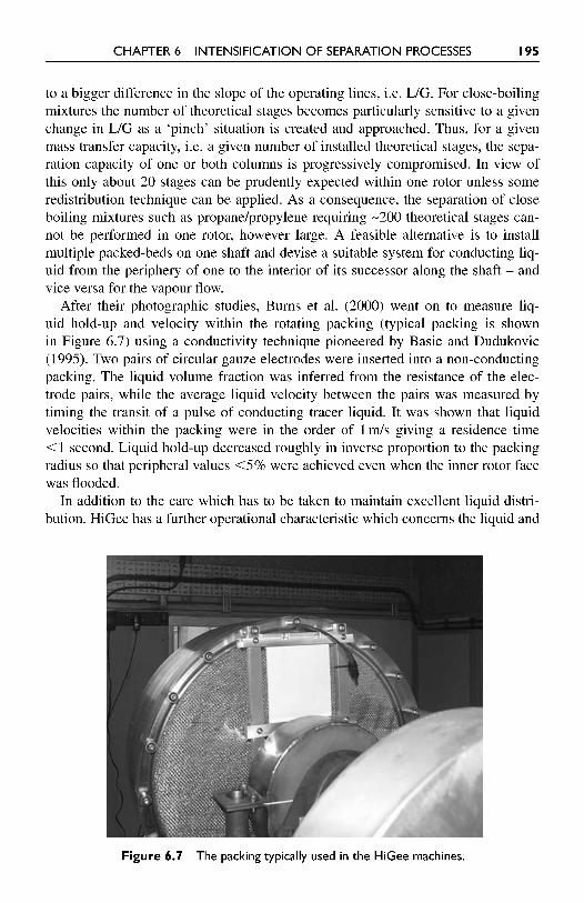
After their photographic studies, Burns et al. (2000) went on to measure liq- uid hold-up and velocity within the rotating packing (typical packing is shown in Figure 6.7) using a conductivity technique pioneered by Basic and Dudukovic (1995). Two pairs of circular gauze electrodes were inserted into a non-conducting packing. The liquid volume fraction was inferred from the resistance of the elec- trode pairs, while the average liquid velocity between the pairs was measured by timing the transit of a pulse of conducting tracer liquid. It was shown that liquid velocities within the packing were in the order of 1 rnls giving a residence time <1 second. Liquid hold-up decreased roughly in inverse proportion to the packing radius so that peripheral values <5% were achieved even when the inner rotor face was flooded.
In addition to the care which has to be taken to maintain excellent liquid distri- bution, HiGee has a further operational characteristic which concerns the liquid and
Figure 6.7 The packing typically used in the HiGee machines.
196 PROCESS INTENSIFICATION
gas behaviour in the 'eye' of the rotor. The flows within the packing correspond to a forced vortex in which the gas and liquid streams rotate at virtually the same angular velocity as the packing. Relative to the packing the flows are nearly radial because the lateral Coriolis acceleration (2v,w where v, is the radial velocity) is small compared to the radial centrifugal acceleration. However, at the centre there is little frictional interaction to compel the fluids to conform to the packing angu- lar velocity, so a free vortex is generated, leading to relatively high tangential gas velocities because angular momentum (tangential velocity X local radius) is main- tained as the radius decreases. These can disrupt the liquid flow leaving the distrib- utors and, in the limit, remove the liquid before it reaches the packing surface. The liquid distributor must be designed to overcome this problem.
6.2.3.1 Principal HiGee operating features The radial thickness of the rotor is directly related to the separation duty and the corresponding number of stages required, noting the stage heights given above. The hydraulic capacity depends upon the flooding rates at the inner radius and the inner cylindrical surface area. Typically operation at about 50% of the flooding rates can be prudently adopted. Generally the pressure drop incurredltheoretical stage will be equivalent to that generated by a trayed column rather than the lower value of its packed equivalent. Hence the HiGee characteristics of most interest are:
Small footprintllow height Residence time - 1 second Very low process inventory.
Performance is not influenced by changes in orientation, e.g. when barge or ship- mounted. Applications which are particularly suited to HiGee are therefore where space, weight or hazardous inventory cause significant concern. This could include many offshore or sea-going installations. HiGee may be difficult to justify when rel- atively cheap column construction materials such as mild steel or polymers will suf- fice. However, if stainless steel or other more expensive corrosion resistant material is needed, then HiGee becomes attractive. Finally, the pressure drops within a rotor will largely rule it out for high vacuum duties in its present state of development. It is more appropriate for operation at or above one bar. Since it has proved impracti- cal to provide feedlofftakes at a mid-radial position, distillation duties require two separate rotors, preferably on one shaft, with an intermediate liquid supply.
In its present configuration the HiGee rotating packed-bed concept only applies the elevated acceleration to the mass transfer element of a distillation operation. However, it is worth noting that the associated reboiler and condenser functions both involve multiple phases. They could therefore benefit from inclusion within the rotor, leading to a peripheral reboiler and a central condenser. This would lead to a further development of the PI strategy by the provision of multi-functional units, see Figure 6.8.
Recent research in China (Wang et al., 2007) has led to what is claimed to be a new HiGee - a rotating zigzag bed (RZB). The RZB is claimed to function without
CHAPTER 6 INTENSIFICATION OF SEPARATION PROCESSES 197
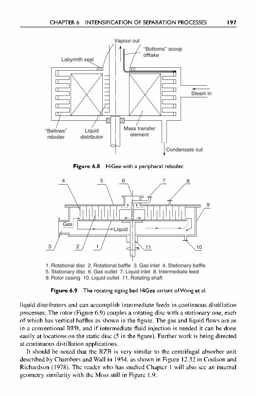
Figure 6.8 HiGee with a peripheral reboiler.
Figure 6.9 The rotating zigzag bed HiGee variant ofWang et al.
liquid distributors and can accomplish intermediate feeds in continuous distillation processes. The rotor (Figure 6.9) couples a rotating disc with a stationary one, each of which has vertical baffles as shown in the figure. The gas and liquid flows are as in a conventional RPB, and if intermediate fluid injection is needed it can be done easily at locations on the static disc (5 in the figure). Further work is being directed at continuous distillation applications.
It should be noted that the RZB is very similar to the centrifugal absorber unit described by Chambers and Wall in 1954, as shown in Figure 12.32 in Coulson and Richardson (1978). The reader who has studied Chapter 1 will also see an internal geometry similarity with the Moss still in Figure 1.9.
Condensate out
Steam in
Labyrinth seal
Vapour out
‘‘Bottoms’’ scoopofftake
Mass transferelement
Liquiddistributor
‘‘Bellows’’reboiler
Gas
3 2 1
Liquid
11 10
9
87654
1. Rotational disc 2. Rotational baffle 3. Gas inlet 4. Stationary baffle5. Stationary disc 6. Gas outlet 7. Liquid inlet 8. Intermediate feed9. Rotor casing 10. Liquid outlet 11. Rotating shaft
198 PROCESS INTENSIFICATION
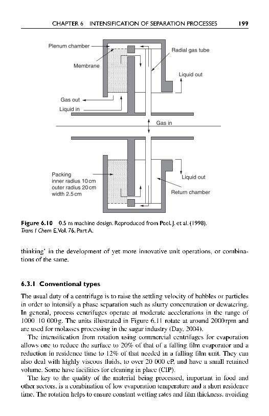
6.2.3.2 Phase inversion The HiGee concept was originally based on a continuous gas phase in which liquid was dispersed over the packing. As noted above, this currently results in liq- uid being discharged into the machine case at the rotor tip speed. While the cor- responding loss of kinetic energy can perhaps be accepted for the modest flows encountered in most distillation and absorption duties, it can become an issue when very large flows of water need to be deaerated for oilfield reinjection. In this case the flows are -500 tonneslhour and a technique for energy recovery may be attrac- tive. This can be largely achieved by inverting the phases so that gas is dispersed as bubbles within a continuous liquid immersed in the packing (Peel et al., 1998). A schematic arrangement is shown in Figure 6.10, where the rotor is divided into two compartments, one containing the packing and the other allowing liquid to return to the inner radius for discharge. The arrangement operates essentially as a centrifu- gal lute which permits liquid to leave with only about 10% of the kinetic energy corresponding to the tip speed. It goes without saying that the return chamber must be fitted with radial baffles to suppress the freevortex which would otherwise occur. A significant pressure gradient is created within the rotor and the gas must be supplied at a sufficient pressure to overcome this. However for absorptionlstripping duties which involve sparingly soluble gases, the gas mass flow is much smaller than that of the liquid, so the energy implications are expected to be acceptable. Indeed in many cases the stripping gas, e.g. methane or nitrogen, may be available at a sufficient pressure.
Peel et al. (1998) and Ramshaw et al. (1967) also describe a study carried out to investigate bubble impact with simulated packing. It was shown that there was a critical bubble diameter below which bubble breakdown did not occur. The critical value was a function of density difference, collision velocity and the applied accel- eration. It was predicted, and experimentally demonstrated, that higher acceleration environments could reduce the critical size and thereby lead to a much smaller size distribution. Provided that the bubbles could reach a substantial fraction of their terminal velocity before impact with packing elements, this implies that high volu- metric mass transfer rates should be achievable. The reticulated packing cells must be larger than the bubble diameter in order to realise this condition. This design of rotor (1 m diameter, 0.015 m axial thickness) has been operated as a pilot plant unit at Newcastle University, where it reduced the oxygen concentration in 15 tonnesl hour simulated seawater from 9 ppm to 0.5 ppm.
6.3 CENTRIFUGES
It is not intended to dwell upon the conventional centrifuge in this book. However, the disc-bowl type is worthy of mention, as is the ultra-centrifuge used in the nuclear reprocessing field (see also Chapter 10). All centrifuges are 'active' intensi- fication techniques, and those familiar with centrifuge technology may see parallels between this and HiGee (and spinning disc reactors) that may allow some 'lateral
CHAPTER 6 INTENSIFICATION OF SEPARATION PROCESSES 199
Figure 6. I 0 0.5 m machine design. Reproduced from Peel, J. et al. (1 998). Trans I Chem E,Vol. 76, Part A.
thinking' in the development of yet more innovative unit operations, or combina- tions of the same.
6.3.1 Conventional types
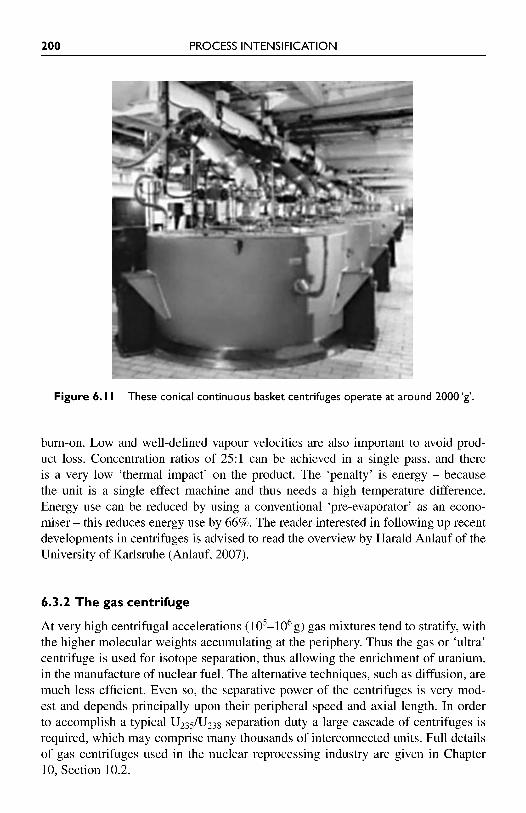
The usual duty of a centrifuge is to raise the settling velocity of bubbles or particles in order to intensify a phase separation such as slurry concentration or dewatering. In general, process centrifuges operate at moderate accelerations in the range of 1000-10 000g. The units illustrated in Figure 6.11 rotate at around 2000rpm and are used for molasses processing in the sugar industry (Day, 2004).
The intensification from rotation using commercial centrifuges for evaporation allows one to reduce the surface to 20% of that of a falling film evaporator and a reduction in residence time to 12% of that needed in a falling film unit. They can also deal with highly viscous fluids, to over 20 000 cP, and have a small retained volume. Some have facilities for cleaning in place (CIP).
The key to the quality of the material being processed, important in food and other sectors, is a combination of low evaporation temperature and a short residence time. The rotation helps to ensure constant wetting rates and film thickness, avoiding
Gas in
Gas out
Liquid in
Liquid out
Radial gas tubePlenum chamber
Membrane
Liquid out
Return chamber
Packinginner radius 10 cmouter radius 20 cmwidth 2.5 cm
200 PROCESS INTENSIFICATION
Figure 6.1 I These conical continuous basket centrifuges operate at around 2000 'g'.
bum-on. Low and well-defined vapour velocities are also important to avoid prod- uct loss. Concentration ratios of 25:l can be achieved in a single pass, and there is a very low 'thermal impact7 on the product. The 'penalty' is energy - because the unit is a single effect machine and thus needs a high temperature difference. Energy use can be reduced by using a conventional 'pre-evaporator' as an econo- miser - this reduces energy use by 66%. The reader interested in following up recent developments in centrifuges is advised to read the overview by Harald Anlauf of the University of Karlsruhe (Anlauf, 2007).
6.3.2 The gas centrifuge
At very high centrifugal accelerations ( 1 0 ~ - 1 0 ~ ~ ) gas mixtures tend to stratify, with the higher molecular weights accumulating at the periphery. Thus the gas or 'ultra' centrifuge is used for isotope separation, thus allowing the enrichment of uranium, in the manufacture of nuclear fuel. The alternative techniques, such as diffusion, are much less efficient. Even so, the separative power of the centrifuges is very mod- est and depends principally upon their peripheral speed and axial length. In order to accomplish a typical U235/U238 separation duty a large cascade of centrifuges is required, which may comprise many thousands of interconnected units. Full details of gas centrifuges used in the nuclear reprocessing industry are given in Chapter 10, Section 10.2.
CHAPTER 6 INTENSIFICATION OF SEPARATION PROCESSES 20 1
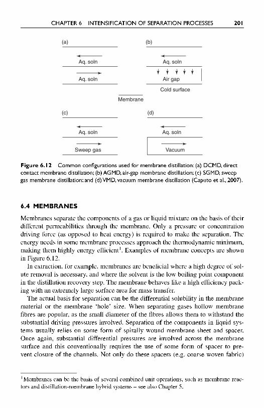
Figure 6.12 Common configurations used for membrane distillation: (a) DCMD, direct contact membrane distillation; (b) AGMD, air-gap membrane distillation; (c) SGMD, sweep gas membrane distillation; and (d) VMD, vacuum membrane distillation (Caputo et al., 2007).
6.4 MEMBRANES
Membranes separate the components of a gas or liquid mixture on the basis of their different permeabilities through the membrane. Only a pressure or concentration driving force (as opposed to heat energy) is required to make the separation. The energy needs in some membrane processes approach the thermodynamic minimum, making them highly energy efficient1. Examples of membrane concepts are shown in Figure 6.12.
In extraction, for example, membranes are beneficial where a high degree of sol- ute removal is necessary, and where the solvent is the low boiling point component in the distillation recovery step. The membrane behaves like a high efficiency pack- ing with an extremely large surface area for mass transfer.
The actual basis for separation can be the differential solubility in the membrane material or the membrane 'hole' size. When separating gases hollow membrane fibres are popular, as the small diameter of the fibres allows them to withstand the substantial driving pressures involved. Separation of the components in liquid sys- tems usually relies on some form of spirally wound membrane sheet and spacer. Once again, substantial differential pressures are involved across the membrane surface and this conventionally requires the use of some form of spacer to pre- vent closure of the channels. Not only do these spacers (e.g. coarse woven fabric)
' Membranes can be the basis of several combined unit operations, such as membrane reac- tors and distillation-membrane hybrid systems - see also Chapter 5.
Aq. soln
Aq. soln
Aq. soln
Air gap
(a) (b)
Aq. soln
Sweep gas
Aq. soln
Membrane
Cold surface
Vacuum
(c) (d)
202 PROCESS INTENSIFICATION
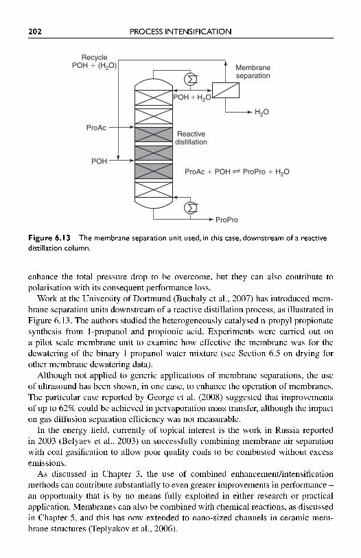
Figure 6.13 The membrane separation unit used, in this case, downstream of a reactive distillation column.
enhance the total pressure drop to be overcome, but they can also contribute to polarisation with its consequent performance loss.
Work at the University of Dortmund (Buchaly et al., 2007) has introduced mem- brane separation units downstream of a reactive distillation process, as illustrated in Figure 6.13. The authors studied the heterogeneously catalysed n-propyl propionate synthesis from 1-propanol and propionic acid. Experiments were carried out on a pilot scale membrane unit to examine how effective the membrane was for the dewatering of the binary 1-propanol-water mixture (see Section 6.5 on drying for other membrane dewatering data).
Although not applied to generic applications of membrane separations, the use of ultrasound has been shown, in one case, to enhance the operation of membranes. The particular case reported by George et al. (2008) suggested that improvements of up to 62% could be achieved in pervaporation mass transfer, although the impact on gas diffusion separation efficiency was not measurable.
In the energy field, currently of topical interest is the work in Russia reported in 2003 (Belyaev et al., 2003) on successfully combining membrane air separation with coal gasification to allow poor quality coals to be combusted without excess emissions.
As discussed in Chapter 3, the use of combined enhancementlintensification methods can contribute substantially to even greater improvements in performance - an opportunity that is by no means fully exploited in either research or practical application. Membranes can also be combined with chemical reactions, as discussed in Chapter 5, and this has now extended to nano-sized channels in ceramic mem- brane structures (Teplyakov et al., 2006).
RecyclePOH � (H2O)
POH�H2O
H2O
Reactivedistillation
Membraneseparation
ProAc
ProPro
POHProAc � POH ProPro � H2O
CHAPTER 6 INTENSIFICATION OF SEPARATION PROCESSES 203
6.5 DRYING
Dryers are integral parts of a large number of industrial processes and are used in sectors ranging from pharmaceuticals to textiles and ceramics. We commonly asso- ciate drying with solids, but gases frequently require drying and dehumidification in industry and in buildings drying is growing in importance.
After distillation and evaporation, drying is the next major process energy user and spans a wider variety of sectors than distillation. Drying of solids normally involves removal of water, but in general any liquid removed from a solid is clas- sified as drying. The separation is carried out most frequently by either mechani- cal means, e.g. pressing or thermally - the application of heat via a hot air stream, for example. Gas drying can be carried out by a number of thermodynamic cycles, such as vapour compression and adsorption. Gas dehydration is important in natu- ral gas processing, for example, and membranes may be used. Where a proportion of the liquid present is removed, the term 'dewatering' may be applied. It is com- monly associated with sludge and 'cake' materials.
The majority of solids dryers use heat to remove moisture from the solid objects, which may range from micro-particles to large blocks of material, such as plaster- board. The general aim of dryer improvements is to intensify the process - to dry the product in as short a time as possible, using the minimum amount of energy, without degrading the product in any way. Because passing hot air over the surface of a solid is not particularly effective as a moisture removal method, unless the particles are small, techniques which excite the moisture molecules directly within the solid, rather than relying upon the solid thermal conductivity, are seen as inten- sive procedures. Electric fields can be used here, as discussed below. The reader may also consider processes such a freeze drying and fluidised-bed drying (see the Torbed, Chapter 5 ) which can, depending upon the nature of the product, both speed up moisture removal and reduce the size of drying plant. Where energy effi- ciency is important, heat pump assisted dryers may also be effective - there are a number of variants of these, some of which are discussed in this chapter.
Crystallisation may be related to drying, in that moisture removal from a solu- tion can lead to a solid being formed. The processes used, however, are different although they may be classified, like drying, as separations. Crystallisation has not received the attention given to other separation methods, in the context of either energy saving or PI.
6.5.1 Electric drying and dewatering methods
In this section, electrical drying methods are briefly discussed - examples of appli- cations are discussed in Chapter 10. As an example, the industrial microwave dryer exhibits similar benefits to the domestic microwave oven - the energy is taken directly to the inside of the object(s) being heated, rather than having to be con- ducted from the surface of the particle or body. Microwave drying can be combined with conventional (hot air) drying to 'finish off' the process, and a combination of
204 PROCESS INTENSIFICATION
steam and microwaves has been used where cooking is needed, for example with chickens. Radio frequency (r.f.) energy can also be used for drying, as can resist- ance heating. A further discussion of electrical enhancement is given in Chapter 3.
6.5.1.1 Microwaves Some of the best examples of microwave drying applications originate in the food industry (see Chapter 10). Pasta drying, as an example, is a very slow process using conventional means, taking 10-20 hours at 40°C in large hot air recirculating ovens. In the US a 1500 kglh pasta oven using 60 kW of microwave power, together with hot air, dries the pasta in 15 minutes. As well as increased production rates, the dryer is smaller and the product is bacteriologically more acceptable.
The use of microwaves as part of a hybrid drying system can bring additional sav- ings, as described in a study of cast ceramic ware (Anon, 1992). Here cast ceramic ware used both microwave energy and vacuum to aid the drying process. Interestingly, reductions in drying processing times approaching those achieved for reactions with spinning disc reactors (SDRs), see Chapter 5 , were achieved, ware drying times being reduced from hours to minutes. Energy use was 26% of the conventional system.
Because one is using a relatively expensive form of energy in delivering microwave or r.f. (radio frequency) heating, they are often used solely as the final - more difficult - stage of moisture removal. In one case the drying of onions required moisture levels to reduce from 80% to 10%. It was most cost-effective to use the microwave dryer for the final drying, from 20% to 10% moisture, resulting in a 30% reduction in energy costs of the final drying stage and lowering the bacteria count by 90%.
6.5.1.2 Radio frequency fields Capenhurst.tech supplemented mechanical dewatering (e.g. filter pressing) of slur- ries by using an r.f. field and a vacuum, which of course allows easier removal of water vapour. The system should reduce processing times, improve product qual- ity and reduce the need for ancillary equipment. Applications are envisaged in the food, chemicals, pharmaceutical and agricultural sectors. R.f. assisted dewatering could, say Capenhurst.tech, have uses in effluent treatment.
6.5.2 Membranes for dehydration
Several processes need to be carried out before natural gas can be safely released into transmission pipelines. The removal of water is one of these and an improved system based upon membranes, already successfully used for C02 removal, was tested some years ago by the US Gas Technology Institute (GTI). The system was expected to result in a 50-70% reduction in size and weight of the dehydration unit.
Shell Global Solutions is another company which has studied membranes for conditioning of natural gas (Rijkens, 2000; Rijkens et al., 2001). Among the membrane types which can be used for gas separationldrying are hollow fibre units. Membranes have been used by Shell Oil, who applied a Kvaerner-designed
CHAPTER 6 INTENSIFICATION OF SEPARATION PROCESSES 205
membrane contactor successfully for dehydration. Reductions in absorber weight of up to 70% were claimed.
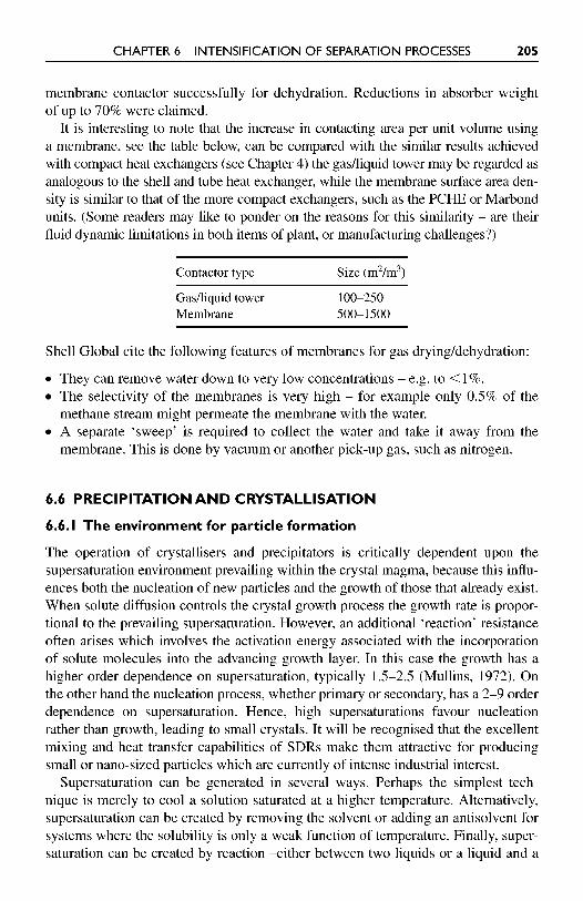
It is interesting to note that the increase in contacting area per unit volume using a membrane, see the table below, can be compared with the similar results achieved with compact heat exchangers (see Chapter 4) the gaslliquid tower may be regarded as analogous to the shell and tube heat exchanger, while the membrane surface area den- sity is similar to that of the more compact exchangers, such as the PCHE or Marbond units. (Some readers may like to ponder on the reasons for this similarity - are their fluid dynamic limitations in both items of plant, or manufacturing challenges?)
Contactor type Size (m2/m3)
Gadliquid tower 100-250 Membrane 500-1 500
Shell Global cite the following features of membranes for gas dryingldehydration:
They can remove water down to very low concentrations - e.g. to < 1%. The selectivity of the membranes is very high - for example only 0.5% of the methane stream might permeate the membrane with the water. A separate 'sweep' is required to collect the water and take it away from the membrane. This is done by vacuum or another pick-up gas, such as nitrogen.
6.6 PRECIPITATION A N D CRYSTALLISATION
6.6.1 The environment for particle formation
The operation of crystallisers and precipitators is critically dependent upon the supersaturation environment prevailing within the crystal magma, because this influ- ences both the nucleation of new particles and the growth of those that already exist. When solute diffusion controls the crystal growth process the growth rate is propor- tional to the prevailing supersaturation. However, an additional 'reaction' resistance often arises which involves the activation energy associated with the incorporation of solute molecules into the advancing growth layer. In this case the growth has a higher order dependence on supersaturation, typically 1.5-2.5 (Mullins, 1972). On the other hand the nucleation process, whether primary or secondary, has a 2-9 order dependence on supersaturation. Hence, high supersaturations favour nucleation rather than growth, leading to small crystals. It will be recognised that the excellent mixing and heat transfer capabilities of SDRs make them attractive for producing small or nano-sized particles which are currently of intense industrial interest.
Supersaturation can be generated in several ways. Perhaps the simplest tech- nique is merely to cool a solution saturated at a higher temperature. Alternatively, supersaturation can be created by removing the solvent or adding an antisolvent for systems where the solubility is only a weak function of temperature. Finally, super- saturation can be created by reaction -either between two liquids or a liquid and a
206 PROCESS INTENSIFICATION
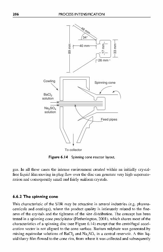
Figure 6.14 Spinning cone reactor layout.
gas. In all these cases the intense environment created within an initially crystal- free liquid film moving in plug flow over the disc can generate very high supersatu- ration and consequently small and fairly uniform crystals.
6.6.2 The spinning cone
This characteristic of the SDR may be attractive in several industries (e.g. pharrna- ceuticals and coatings), where the product quality is intimately related to the fine- ness of the crystals and the tightness of the size distribution. The concept has been tested in a spinning cone precipitator (Hetherington, 2001), which shares most of the characteristics of a spinning disc (see Figure 6.14) except that the centrifugal accel- eration vector is not aligned to the cone surface. Barium sulphate was generated by mixing equimolar solutions of BaC12 and Na2S04 in a central reservoir. A thin liq- uidlslurry film flowed to the cone rim, from where it was collected and subsequently
To collector
Feed pipes
26 mm
40 mm
34°
89 m
m
33 m
m
17 m
m
48 mm
Spinning coneCowling
BaCl2solution
Na2SO4solution
CHAPTER 6 INTENSIFICATION OF SEPARATION PROCESSES 207
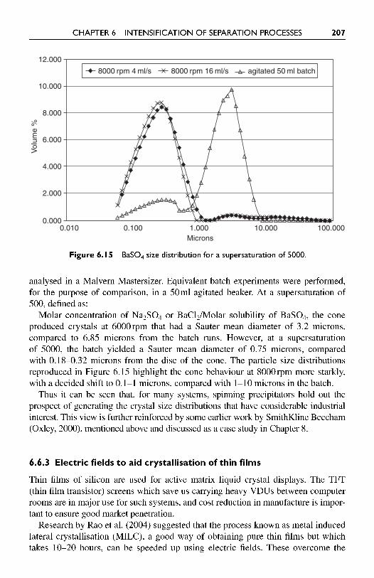
Figure 6.15 BaS04 size distribution for a supersaturation of 5000.
analysed in a Malvern Mastersizer. Equivalent batch experiments were performed, for the purpose of comparison, in a 50ml agitated beaker. At a supersaturation of 500, defined as:
Molar concentration of Na2S04 or BaC12/Molar solubility of BaS04, the cone produced crystals at 6000rpm that had a Sauter mean diameter of 3.2 microns, compared to 6.85 microns from the batch runs. However, at a supersaturation of 5000, the batch yielded a Sauter mean diameter of 0.75 microns, compared with 0.18-0.32 microns from the disc of the cone. The particle size distributions reproduced in Figure 6.15 highlight the cone behaviour at 8000rpm more starkly, with a decided shift to 0.1-1 microns, compared with 1-10 microns in the batch.
Thus it can be seen that, for many systems, spinning precipitators hold out the prospect of generating the crystal size distributions that have considerable industrial interest. This view is further reinforced by some earlier work by SmithKline Beecham (Oxley, 2000), mentioned above and discussed as a case study in Chapter 8.
6.6.3 Electric fields to aid crystallisation of thin films
Thin films of silicon are used for active matrix liquid crystal displays. The TFT (thin film transistor) screens which save us carrying heavy VDUs between computer rooms are in major use for such systems, and cost reduction in manufacture is impor- tant to ensure good market penetration.
Research by Rao et al. (2004) suggested that the process known as metal induced lateral crystallisation (MILC), a good way of obtaining pure thin films but which takes 10-20 hours, can be speeded up using electric fields. These overcome the
100.00010.0001.000Microns
0.1000.0100.000
2.000
4.000
6.000
Vol
ume
%
8.000
10.000
12.000
8000 rpm 4 ml/s 8000 rpm 16 ml/s agitated 50 ml batch
208 PROCESS INTENSIFICATION
slow thermal diffusion of Nisi2, which governs the speed of crystallisation, allow- ing the time to be reduced. Another benefit of the use of this method is the way the applied field can encourage directional crystal growth. This aids electrical mobility in the device. In the case here, microwave annealing was used to produce crystal films in 50 minutes. More recently Hong et al. (2007) have encouraged even more rapid crystal formation by electrically heating the thin film.
6.7 MOP FANIDEDUSTER
As discussed in Chapter 6, the rotating packed-bed is an intense device for pro- viding counter-current flow within a packing having a relatively high specific sur- face area. From a thermodynamic point of view, counter-current flow is beneficial when operating a distillation or absorption process because local concentration dif- ferences and the associated entropy gain may be minimised. Therefore, when high efficiency is critical, the counter-current approach is adopted. However, there are some phase disengagement and mass transfer duties where efficiency is not of par- amount importance and for which co-current flow of the phases can be tolerated. This avoids the flow restrictions imposed by flooding considerations and leads to a simpler device. It was against this background that Byrd (1986) invented the mop fan, initially for lime dust capture at ICI's quarry near Buxton.
6.7.1 Description of the equipment
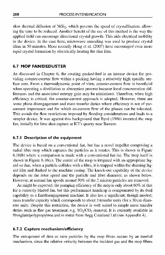
The device is based on a conventional fan, but has a novel impeller comprising a radial fibre mop which captures the particles as it rotates. This is shown in Figure 6.16(b) where a comparison is made with a conventional fan (a). The mop itself is shown in Figure 6.16(c). The centre of the mop is irrigated with an appropriate liq- uid so that, when a particle collides with a fibre, it is trapped within the draining liq- uid film and flushed to the machine casing. The knock-out capability of the device depends on the rotor speed and the particle and fibre diameter, as shown below. However, at normal fan speeds around 50% of the 2 micron particles are removed.
As might be expected, the pumping efficiency of the mop is only about 60% of that for a correctly bladed fan, but this performance handicap is compensated by its dual capability as a fanldisengagement machine. It also has a significant, though modest, mass transfer capacity which corresponds to about 3 transfer units (for a 30cm diam- eter unit). Despite this restriction, the device is well suited to simple mass transfer duties such as flue gas treatment, e.g. SO21CO2 removal. It is currently available in fibreglass/polypropylene and in metal from Begg Cousland Ltd (see Appendix 4).
6.7.2 Capture mechanismlefficiency
The entrapment of dust or mist particles by the mop fibres occurs by an inertial mechanism, since the relative velocity between the incident gas and the mop fibres
CHAPTER 6 INTENSIFICATION OF SEPARATION PROCESSES 209
Figure 6.16 (a) A conventional fan (b) the mop fan showing its internal structure (c) the actual mop.
is a substantial fraction of the tip speed of the mop. The particle capture process can be appreciated from Figure 6.17, which sketches the air flow around a fibre and shows an upstream particle as it begins to negotiate its way around the fibre, which is shown in circular cross-section. If the mass within an imaginary particle surface corresponded to the fluid density, then the particle would follow the streamline as
Motor
High capacity centrifugal fan with conventionalrigid impeller
High inertiaCareful balancing requiredDirt initiates vibrationDangerous failure modeHigh cost
Airout
(a)
Airin
Motor
Low inertiaVibration freeSelf-cleaningHigh safety factorLow costSpecial scrubbing facility
Airout
Airin
High capacity centrifugal fan with novel flexiblefibre impeller
(b)
(c)
2 10 PROCESS INTENSIFICATION
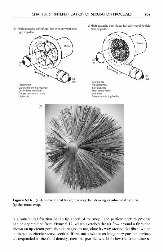
Figure 6.17 The mop fan particle capture process.
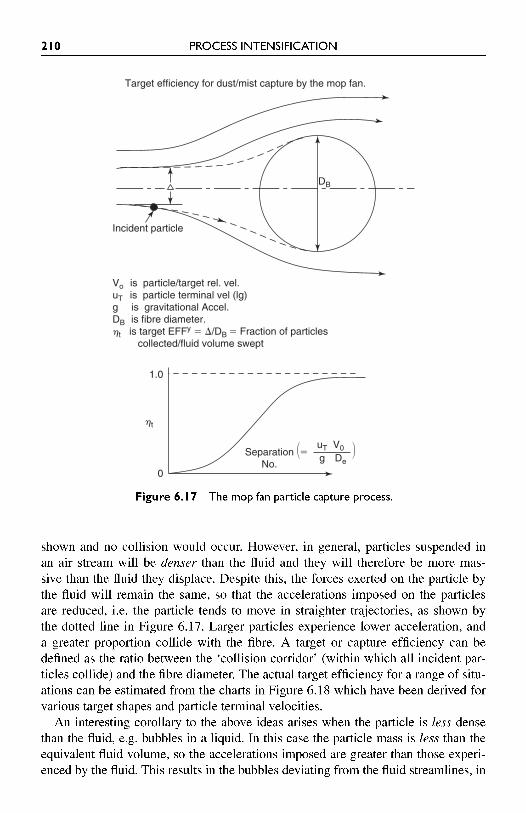
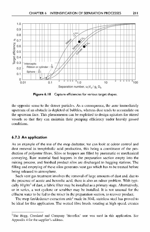
shown and no collision would occur. However, in general, particles suspended in an air stream will be denser than the fluid and they will therefore be more mas- sive than the fluid they displace. Despite this, the forces exerted on the particle by the fluid will remain the same, so that the accelerations imposed on the particles are reduced, i.e. the particle tends to move in straighter trajectories, as shown by the dotted line in Figure 6.17. Larger particles experience lower acceleration, and a greater proportion collide with the fibre. A target or capture efficiency can be defined as the ratio between the 'collision corridor' (within which all incident par- ticles collide) and the fibre diameter. The actual target efficiency for a range of situ- ations can be estimated from the charts in Figure 6.18 which have been derived for various target shapes and particle terminal velocities.
An interesting corollary to the above ideas arises when the particle is less dense than the fluid, e.g. bubbles in a liquid. In this case the particle mass is less than the equivalent fluid volume, so the accelerations imposed are greater than those experi- enced by the fluid. This results in the bubbles deviating from the fluid streamlines, in
Target efficiency for dust/mist capture by the mop fan.
DB
Incident particle
Vo is particle/target rel. vel.uT is particle terminal vel (lg)g is gravitational Accel.DB is fibre diameter.ht is target EFFy � �/DB � Fraction of particles collected/fluid volume swept
SeparationNo.
1.0
0
ht
� �uT V0g De
�
CHAPTER 6 INTENSIFICATION OF SEPARATION PROCESSES 21 1
Figure 6.18 Capture efficiencies for various target shapes.
the opposite sense to the denser particles. As a consequence, the zone immediately upstream of an obstacle is depleted of bubbles, whereas dust tends to accumulate on the upstream face. This phenomenon can be exploited to design agitators for stirred vessels so that they can maintain their pumping efficiency under heavily gassed conditions.
6.7.3 An application
As an example of the use of the mop deduster, we can look at odour control and dust removal in terephthalic acid production, this being a constituent of the pro- duction of polyester fibres. Silos or hoppers are filled by pneumatic or mechanical conveying. Raw material feed hoppers in the preparation section empty into the mixing process, and finished product silos are discharged to bagging stations. The filling and emptying of these silos generates vent gas which has to be treated before being released to atmosphere.
Such vent gas treatment involves the removal of large amounts of dust and, due to the presence of acetic and benzolic acid, there is also an odour problem. With typi- cally 10 g/m3 of dust, a fabric filter may be installed as a primary stage. Alternatively, or in series, a wet cyclone or scrubber may be installed. It is not unusual for the effluent water to be fed to the mixer in the preparation section, to recover product.
The mop fanldeduster extraction unit2 made in 304L stainless steel has proved to be ideal for this application. The wetted fibre brush, rotating at high speed, creates
2 ~ h e Begg, Cousland and Company 'Becoflex' unit was used in this application. See Appendix 4 for the supplier's address.
101.0Separation number, uTVo / gL Db
0.10.010
0.1
0.2
0.3
0.4
Targ
et e
ffici
ency
, ht
0.5
0.6
0.7
0.8
0.9
1.0
3 4 6 852 3 4 6 852100
Intercepts: 116Ribbon or cylinder :
124Sphere :
Ribbon
Spher
e
Cylind
er
D b
D b
D b
212 PROCESS INTENSIFICATION
an extremely dynamic gas contact, which removes solids, absorbs or dehumidifies gas and acts as its own air mover - all in the single piece of plant. In the vent gas steam it scrubs the odour (100% odour removal using a 5% NaOH solution spray) and removes any residual dust. The unit is located in the silo roof to minimise duct- ing. Interestingly, there is no extra pressure drop - in fact it has been shown that, with pneumatically fed hoppers, the air movement induced by the mop assists the vacuum effect in the silo.
6.8 SUMMARY
This chapter deals with an important area of PI - that of separations. There are many types of equipment used, including a range of 'active7 methods, and in com- mon with other unit operations many can fulfil dual (or multiple) roles, such as separation plus reactions. An appreciation of this fact is a major step in becoming fully aware of the potential of PI in radically changing process plant.
REFERENCES
Anlauf, H. (2007). Recent developments in centrifuge technology. Separation and Pur$cation Technology, Vol. 58, pp. 242-246.
Anon, (1992). Microwave/vacuum drying of cast ceramic ware. Energy Efficiency Office Best Practice Programme, New Practice Final Profile 40, September.
Basic, A. and Dudukovic, M.P. (1995). Liquid holdup in rotating packed beds: examination of the film flow assumption. AIChE, Vol. 41, No. 2, pp. 301-316.
Belyaev, A.A. et al. (2003). Membrane air separation for intensification of coal gasification process. Fuel Processing Technology, Vol. 80, pp. 1 19-141.
Buchaly, C., Kreis, P. and Gorak, A. (2007). Hybrid separation processes: combination of reactive distillation with membrane separation. Chemical Engineering and Processing, Vol. 26, pp. 790-799.
Burns, J.R. and Ramshaw, C. (1996). Process intensification: visual study of liquid maldistri- bution in rotating packed beds. Chem. Eng. Sci., Vol. 5 1, No. 8, p. 1347.
Burns, J.R., Jamil, J.N. and Ramshaw, C. (2000). Process intensification: operating charac- teristics of rotating packed beds: determination of liquid hold-up for a high-voidage struc- tured packing. Chem. Eng. Sci., Vol. 55, p. 2401.
Byrd, G. (1986). European Patent No. 176287 (A). Caputo, G., Felici, C., Tarquini, P., Giaconia, A. and Sau, S. (2007). Membrane distillation
of HI/H20 and H2S04/H20 mixtures for the sulphur-iodine thermochemical process. Int. J. Hydrogen Energy,, Vol. 32, pp. 4736-4743.
Coulson, J.M. and Richardson, J.F. (1978). Chemical Engineering. 3rd edn., Vol. 2. Pergamon, Oxford.
Day, N. (2004). Why centrifuges play an important role in the production of sugar. Filtration and Separation, Vol. 41, No. 8, pp. 28-30, October.
Finn, A.J. (1994). Enhancing gas processing with reflux heat exchangers. Chemical Engineering, May.
CHAPTER 6 INTENSIFICATION OF SEPARATION PROCESSES 2 13
George, B.J., Pereira, N., A1 Massum, M., Kolev, A.D. and Ashokkumar, M. (2008). Sensitivity enhancement in membrane separation flow injection analysis by ultrasound. Ultrasonics Sonochemistry, Vol. 15, pp. 15 1-156.
Hetherington, P. et al. (2001). Process intensification: continuous production of barium sulphate using a spinning cone precipitator. 4th International Conference on Process Intensification for the Chemical Industry. Bruges, Belgium. BHR Group Conf. Series, September 10th.
Hong, W.-E. and Ro, J.-S. (2007). Millisecond crystallization of amorphous silicon films by Joule-heating induced crystallization using a conductive layer. Thin Solid Films, Vol. 5 15, pp. 5357-5361.
Kaibel, B. (2007). Distillation - dividing wall columns. Encyclopedia of Separation Science, pp. 1-9. Elsevier, Oxford.
Mallinson, R. and Ramshaw, C. (1979). European Pat No 2568B. Mullins, J.W. (Ed.) (1972). Crystallisation, 2nd edn. Butterworths, London. Oxley, P. et al. (2000). Evaluation of spinning disc reactor technology for the manufacture of
pharmaceuticals. IEC Research, Vol. 39, No. 7, p. 2175. Peel, J., Howarth, C.R. and Ramshaw, C. (1998). Process intensification: HiGee sea water
deaeration. Trans. I. Chem. E., Vol. 76, No. Part A, p. 585. Ramshaw, C. (1993). The opportunities for exploiting centrifugal fields. Heat Recovery
Systems and CHP, Vol. 13, No. 6, p. 493. Ramshaw, C. and Thornton, J.D. (1967). Droplet breakdown in a packed column Part I: the
concept of critical droplet size. I. Chem. E. Symp. Sex, No. 26, p. 73. Rao, R. and Sun, G.C. (2004). Microwave annealing enhances Al-induced lateral crystal-
lization of amorphous silicon thin films. Journal of Crystal Growth, Vol. 273, No. 1-2, pp. 68-73, December 17.
Rijkens, H.C. (2000). Membrane developments for natural gas conditioning. Proceedings of the Symposium: Process Intensification: a challenge for the Process Industry, Rotterdam, October, 10.
Rijkens, H. and Sponselee, J. (2001). Membrane developments for natural gas dehydration. NPT Procestechnologie, No. 2, pp. 5 1-53, March-April.
Sherwood, T.K., Shipley, G.H. and Holloway, F.A.L. (1938). Flooding velocities in packed columns. Ind. Eng. Chem., Vol. 30, p. 765.
Teplyakov, V. et al. (2006). Intensification of gas phase catalytic processes in nano-channels of ceramic catalytic membranes. Desalination, Vol. 199, pp. 16 1-1 63.
Wang, G.Q., Xu, Z.C., Yu, Y.L. and Ji, J.B. (2007). Performance of a rotating zigzag bed - a new HiGee. Chemical Engineering and Processing, doi: 10.1016/j.cep.2007.11.001, 2007.
Wolny, A. and Kaniuk, R. (1995). Intensification of the evaporation process by electric field. Proceedings of the 1st International Conference on Science, Engineering and Technology of Intensive Processing, University of Nottingham, 18-20 September, pp. 79-82, University of Nottingham.