pi multi-objective genetic for lfc based different wind ...with tie-line and using mo-ga to...
TRANSCRIPT

Journal of Power and Energy Engineering, 2018, 6, 76-91 http://www.scirp.org/journal/jpee
ISSN Online: 2327-5901 ISSN Print: 2327-588X
DOI: 10.4236/jpee.2018.67005 Jul. 30, 2018 76 Journal of Power and Energy Engineering
PI Multi-Objective Genetic for LFC Based Different Wind Penetration
Gaber El-Saady1,2, El-Nobi A. Ibrahim1,2, A. A. Donkol1,2
1Electrical Engineering Department, Faculty of Engineering, Assiut University, Assiut, Egypt 2Communication and Computer Engineering Department, Faculty of Engineering, Nahda University, Beni Suef, Egypt
Abstract Future energy descent systems will be expected to be controlled by the using of renewable power sources of which wind energy is one of the favorable sources. This paper treats with the implantation of genetic algorithms for making the parameters needed for PID applied to interconnected thermal and hydraulic power systems at best use and most effective. Two-areas of hy-draulic and thermal power systems with wind connected parallel to each one are considered to exemplify the effective parameter investigation. First hy-draulic and thermal are connected with tie line with the wind connected pa-rallel to hydraulic or thermal, and then disturbance was made at thermal power plant, then to hydraulic power plant. Simulations are performed aided by the integrated Simulink/Matlab environment taking into consideration the genetic optimization process. Multiple integral representations variables with different cost functions were considered in the search for the effective AGC parameters. The outcomes established by this paper shows the impact of the genetic algorithms for LFC about multiple areas connected power systems based on different wind power using in the tuning of such a process.
Keywords PID, Wind, Genetic, Multi-Objective Genetic Algorithm, LFC
1. Introduction
Now, wind energy is the fastest growing and the most widely utilized renewable energy source for the purpose of electric energy descents. Between various RES, wind energy source is the most promising [1]. As the penetration level of the wind energy to the connected power system increases, the control of voltage and frequency turns to be more significant and necessary because of sporadic im-
How to cite this paper: El-Saady, G., Ibra-him, E.-N.A. and Donkol, A.A. (2018) PI Multi-Objective Genetic for LFC Based Different Wind Penetration. Journal of Power and Energy Engineering, 6, 76-91. https://doi.org/10.4236/jpee.2018.67005 Received: July 17, 2018 Accepted: July 27, 2018 Published: July 30, 2018 Copyright © 2018 by authors and Scientific Research Publishing Inc. This work is licensed under the Creative Commons Attribution International License (CC BY 4.0). http://creativecommons.org/licenses/by/4.0/
Open Access
G. El-Saady et al.
DOI: 10.4236/jpee.2018.67005 77 Journal of Power and Energy Engineering
pression of wind power. Thus, the problem of LFC of the interconnected power system having wind power penetration becomes all the more important [1].
The use of Doubly Fed Induction Generator (DFIG) based wind turbine in frequency control has been explored for the purpose in [2] and [3]. In the DFTG’s turbine, inertia is totally decoupled from the system, which means ge-nerators are not supporting to frequency change of the system. Some methods have been reported to show how a variable speed wind turbine participates in frequency control in [4] and [5]. These are based either on inertial control or power reserve control (speed control and pitch control), or on controlling through communication. In the inertial control, an additional loop is introduced with a suitable gain, which is sensitive to the system frequency and provides ki-netic energy from DFTG to support system inertia [6]. In another work, the ro-tor speed and active power were adapted according to de-loaded best power ex-traction curve to deliver ultimate power [6]. Based on the kinetic energy extract from DFIG wind turbines, there are some research works that have been re-ported for load frequency control [7] [8] [9].
In this work, the optimum adjustment of the LFCs used in connected hydrau-lic-power system investigated with the genetic optimization algorithms [10], and also a set of performance indices which are various functions of error and time [11]. In this way, the various performances that the power system might have can be observed when different performance parameters were used.
2. System Model 2.1. Single Diagram
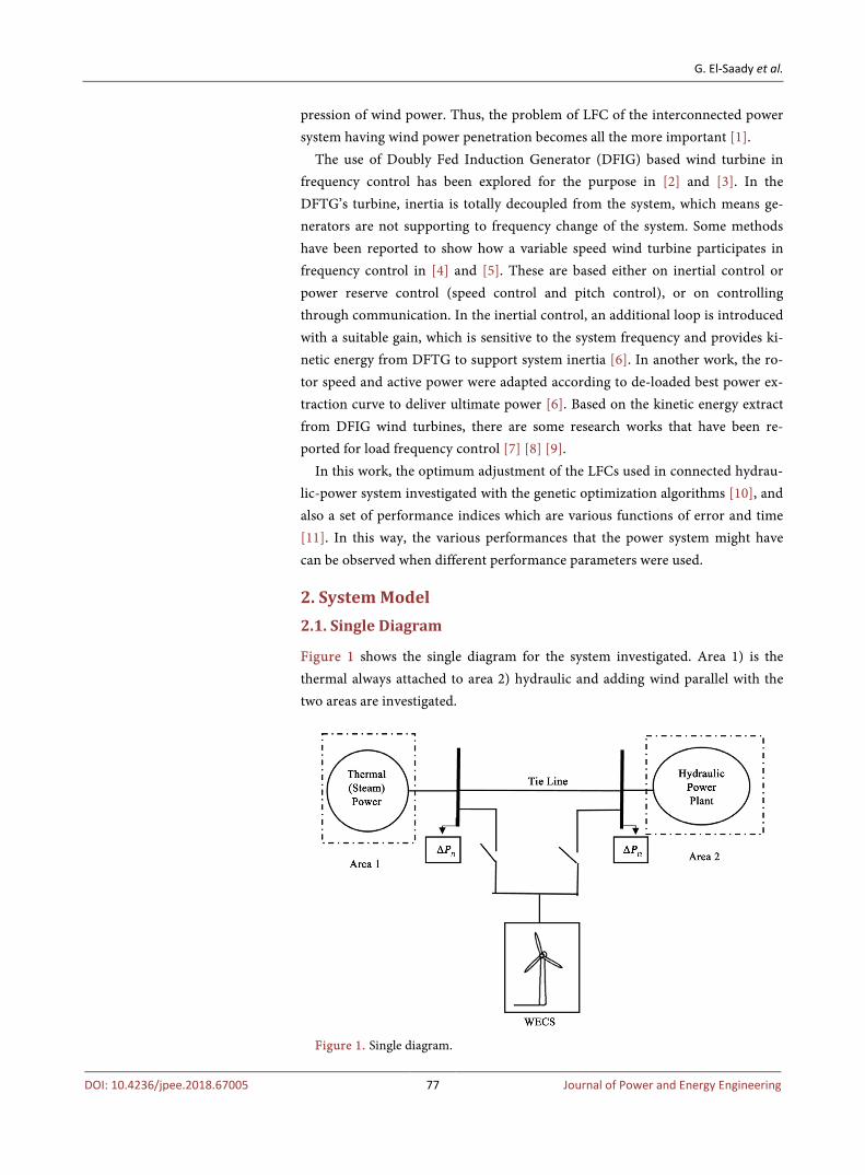
Figure 1 shows the single diagram for the system investigated. Area 1) is the thermal always attached to area 2) hydraulic and adding wind parallel with the two areas are investigated.
Figure 1. Single diagram.
G. El-Saady et al.
DOI: 10.4236/jpee.2018.67005 78 Journal of Power and Energy Engineering
2.2. Block Diagram
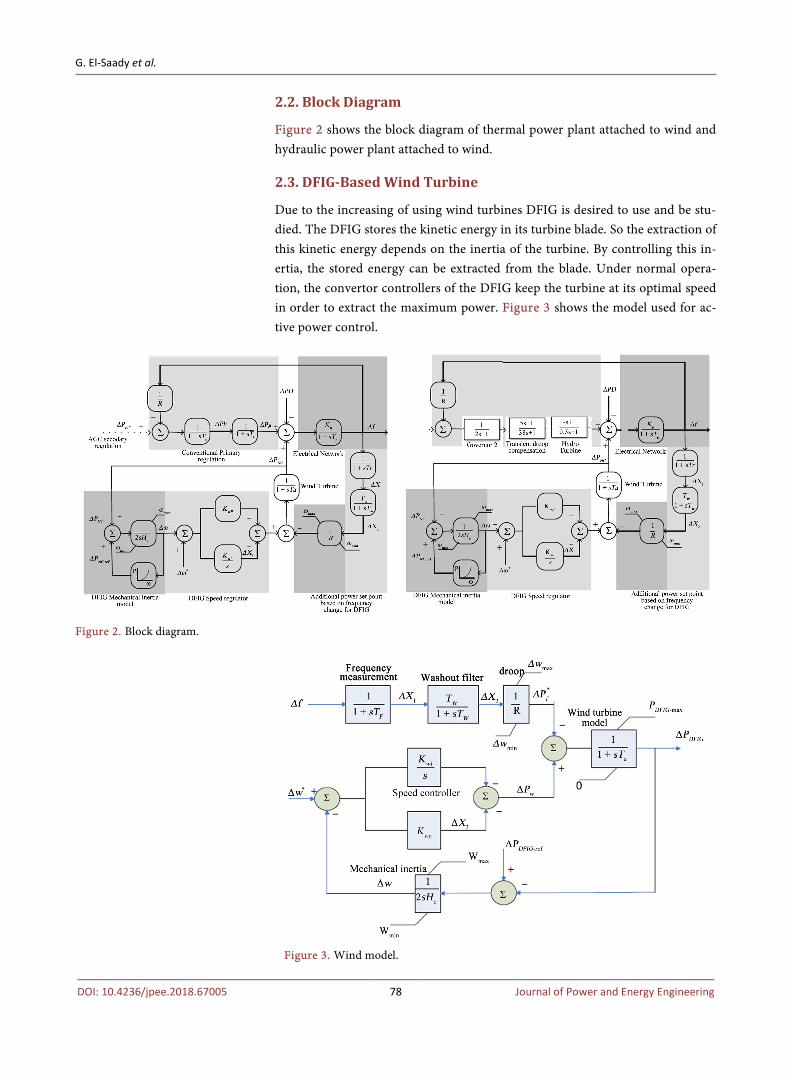
Figure 2 shows the block diagram of thermal power plant attached to wind and hydraulic power plant attached to wind.
2.3. DFIG-Based Wind Turbine
Due to the increasing of using wind turbines DFIG is desired to use and be stu-died. The DFIG stores the kinetic energy in its turbine blade. So the extraction of this kinetic energy depends on the inertia of the turbine. By controlling this in-ertia, the stored energy can be extracted from the blade. Under normal opera-tion, the convertor controllers of the DFIG keep the turbine at its optimal speed in order to extract the maximum power. Figure 3 shows the model used for ac-tive power control.
Figure 2. Block diagram.
Figure 3. Wind model.

G. El-Saady et al.
DOI: 10.4236/jpee.2018.67005 79 Journal of Power and Energy Engineering
3. Multi-Objective Genetic Algorithm (MO-GA) 3.1. Genetic Algorithm (GA)
The GA is a utilization search technique depending on the principles of genetics selection. Population used to evolve under selection rules were allowed by GA to a state that maximizes the “fitness” (i.e., minimizes the cost function), GA was first rise by John Holland in 1975, various versions of programming have been contributed with different prosperity degrees.
Some of the advantages of a GA include [12] [13]: • Variables (continuous - discrete) utilization. • No need for derivative parameters. • Looking simultaneously from many sampling of the cost surface. • Extremely complex utilization of the variables. • Variables encoding so that the utilization encoded variables could be used. • Many data such as numerically generated data, experimental data, or analyt-
ical functions can be used by GA. These advantages made outstanding outcomes when conventional optimiza-
tion approaches cannot get the results. There are wide types of the GAs but the main form is simple genetic algo-
rithm (SGA). SGA functions with various population of candidate solution in-troduced as strings. The first population assembled by random individual gener-ation. Subsequently the fitness of all individual in this population is calculated. Then the population is converted in stages to achieve a new current population for incoming iteration. The conversations were usually calculated in three steps by three genetic operators: 1) Selection genetic operator, 2) Crossover genetic operator, and 3) Mutation genetic operator were detail discussed in [14].
Because of the properties of genetic, which is population based approach, it can be used to solve multi-objective problems [15].
Many various algorithms introduced and perfectly applied to different prob-lems like [16] [17] [18]: Vector-Evaluated GA (VEGA), Multi-Objective GA (MOGA), A Non-Dominated Sorting GA (NSGA) and Non-Dominated Sorting GA (NSGA II) which is used in the proposed research. The Non-Dominated Sorting Genetic Algorithm [19] (NSGA) which is used to find the solutions of multi objective optimizations problems was written by Srinivas and Deb. But has little disadvantages such as wide computational complexity. To decrease these, Deb et al. developed NSGA-II [20]. Mohamed et al. [21] reduce the computa-tional complexity of NSGA II and choose new fitness assignment with Global Ranking Genetic Algorithm (GRGA).
This paper present work achieved by GRMOGA algorithm to solve the LFC problem of two area interconnected power system. The major steps in GRMOGA algorithm are:
1) Global Ranking Fitness Assignment 2) Dominance Rank 3) Crowding Distance.

G. El-Saady et al.
DOI: 10.4236/jpee.2018.67005 80 Journal of Power and Energy Engineering
3.2. Cost Functions
In this paper, the optimal parameters were investigated to adjust of the load fre-quency controllers used in an interconnected hydraulic-thermal and wind power system, with the aim of multi objective genetic algorithms to minimize a set of performance indices which are various functions of error and time. These indic-es include:
( ) 1 2 tiee t f f P= ∆ + ∆ + ∆ (1)
1) The integral of the square of the error criterion (ISE) which is given by:
( )20
ISE de t t∞
= ∫ (2)
2) The integral of time-multiplied absolute value of the error criterion (ITAE) which is given by:
( )0
ITAE dt e t t∞
= ∫ (3)
This criterion penalizes long duration transients and is much more selec-tive than the ISE. A system designed by use of this criterion exhibits small overshoot and well damped oscillations. 3) The integral of time-multiplied square of the error criterion (ITSE) which
is given by:
( )20
ITSE dte t t∞
= ∫ (4)
This criterion weights large initial error lightly, while errors occurring late in the transient response are penalized heavily. This criterion has a better se-lectivity than the ISE. 4) The integral of squared time-multiplied absolute value of the error crite-
rion (ISTAE) which is given by:
( )20
ISTAE dt e t t∞
= ∫ (5)
5) The integral of squared time-multiplied square of the error criterion (ISTSE) which is given by:
( )2 20
ISTSE dt e t t∞
= ∫ (6)
Equations (4)-(6) shows cost functions.
4. Simulation Result and Discussion
This section shows the simulations results of the proposed power system with the results of first disturbance area 1, then area 2, then changing the level of wind penetration. Our power system is thermal connect to hydraulic with tie line, and then adding wind to each side with disturbance at area 1. And do the same but with disturbance at area 2.
4.1. Disturbance Area 1
The change of frequency of area 1, 2 and power of tie line was studied with

G. El-Saady et al.
DOI: 10.4236/jpee.2018.67005 81 Journal of Power and Energy Engineering
our three models hydraulic with thermal, then hydraulic with thermal parallel to wind, at last hydraulic parallel to wind tied with thermal.
4.1.1. Thermal Tied Line with Hydraulic ←→Tie linethermal hydraulic
Figure 4 shows thermal power system connected to hydraulic power system with tie-line and using MO-GA to calculate the parameters of PID controller and the bias frequency B1 and B2 without wind turbine.
The parameters calculated using MO-GA are shown in Table 1.
4.1.2. (Wind Parallel Thermal) Tied Line with Hydraulic ←→Tie linewind & thermal hydraulic
Figure 5 shows thermal power system connected to hydraulic power system with tie-line and using MO-GA to calculate the parameters of PID controller, with wind turbine connected parallel to thermal power system.
The parameters calculated using MO-GA are shown in Table 2. Table 1. The parameters calculated using MO-GA for thermal tied line with hydraluic with disturbance at area 1.
P1 I1 P2 I2 B1 B2
0.399 1.884 13.962 0.1 1 0.996
Table 2. The parameters calculated using MO-GA for thermal parallel to wind tied line with hydraluic with disturbance at area 1.
P1 I1 P2 I2 B1 B2 Kwp kwi
0.399 1.884 13.962 0.1 1 0.996 0.225 0.901
Figure 4. Hydraulic connected with tie-line to thermal with disturbance at area 1.

G. El-Saady et al.
DOI: 10.4236/jpee.2018.67005 82 Journal of Power and Energy Engineering
Figure 5. Hydraulic connected with tie-line to thermal parallel to wind with disturbance at area 1.
4.1.3. (Wind Parallel Hydraulic) Tied Line with Thermal ←→Tie linewind & hydraulic thermal
Figure 6 shows thermal power system connected to hydraulic power system with tie-line and using multi-objective GA to calculate the parameters of PID controller, with wind turbine connected parallel to hydraulic power system.
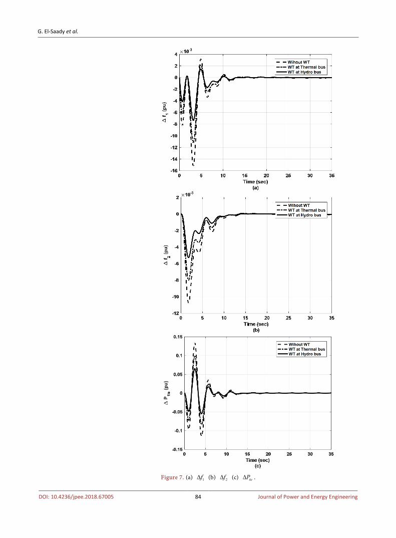
Figure 7 shows a) 1f∆ b) 2f∆ c) tieP∆ with disturbance at area 1 with the three models of our power systems.
The parameters calculated using MO-GA are shown in Table 3.

G. El-Saady et al.
DOI: 10.4236/jpee.2018.67005 83 Journal of Power and Energy Engineering
4.2. Disturbance Area 2
4.2.1. Thermal Tied Line with Hydraulic ←→Tie linethermal hydraulic
Same as section 4.1.1 but with disturbance at area 2 The parameters calculated using MO-GA are shown in Table 4.
4.2.2. Thermal Tied Line with Hydraulic ←→Tie linethermal hydraulic
Same as section 4.1.2 but with disturbance at area 2 The parameters calculated using MO-GA are shown in Table 5.
Figure 6. Hydraulic parallel to wind connected with tie-line to thermal with disturbance at area 1.
G. El-Saady et al.
DOI: 10.4236/jpee.2018.67005 84 Journal of Power and Energy Engineering
Figure 7. (a) 1f∆ (b) 2f∆ (c) tieP∆ .

G. El-Saady et al.
DOI: 10.4236/jpee.2018.67005 85 Journal of Power and Energy Engineering
Table 3. The parameters calculated using MO-GA for hydraluic parallel to wind tied line with thermal with disturbance at area 1.
P1 I1 P2 I2 B1 B2 Kwp kwi
0.399 1.884 13.962 0.1 1 0.996 0.105 0.832
Table 4. The parameters calculated using MO-GA for thermal tied line with hydraluic with disturbance at area 2.
P1 I1 P2 I2 B1 B2
0.381 2.084 14.814 0.8 1.112 1.303
Table 5. The parameters calculated using MO-GA for thermal parallel to wind tied line with hydraluic with disturbance at area 2.
P1 I1 P2 I2 B1 B2 Kwp kwi
0.381 2.084 14.814 0.8 1.112 1.303 0.1 0.343
4.2.3. Thermal Tied Line with Hydraulic ←→Tie linethermal hydraulic
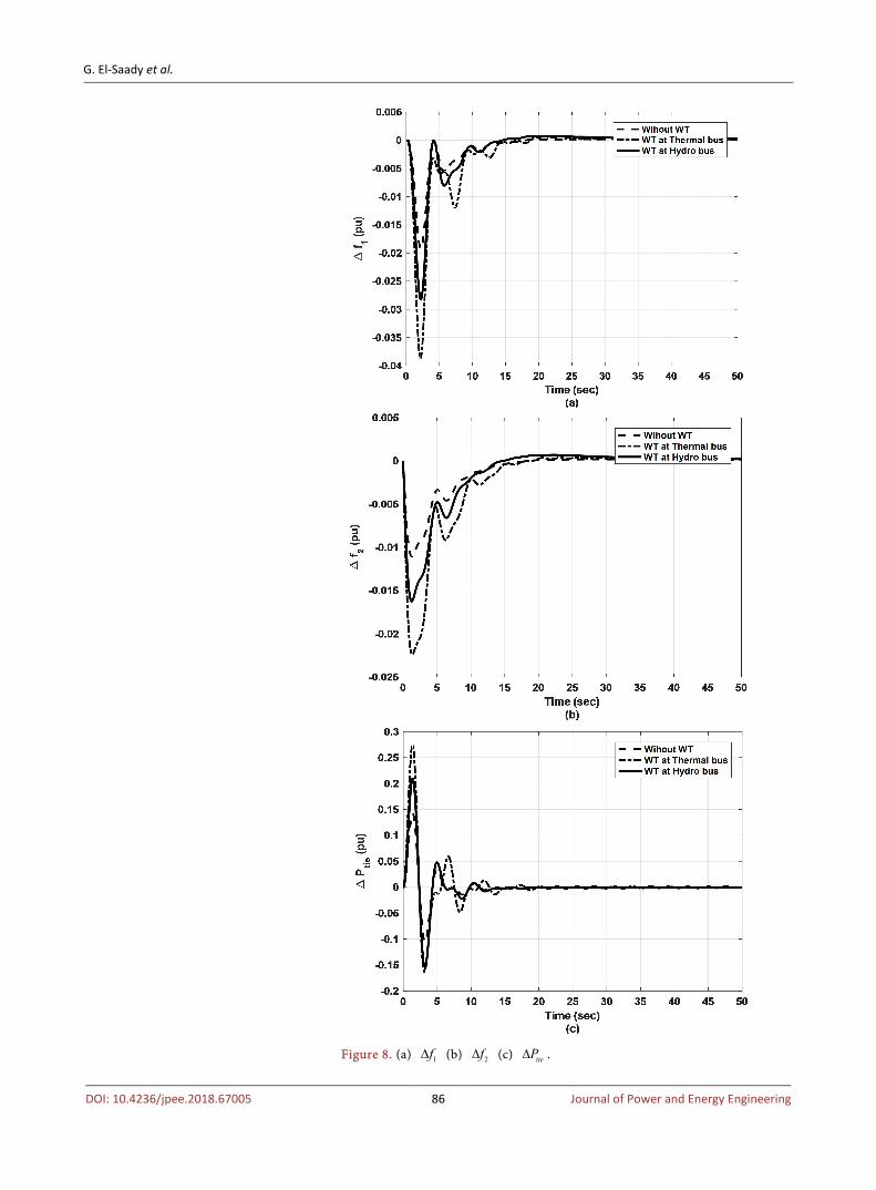
Same as section 4.1.3 but with disturbance at area 2 The parameters calculated using MO-GA are shown in Table 6. Figure 8 shows a) 1f∆ b) 2f∆ c) tieP∆ with disturbance at area 2 with the
three models of our power systems.
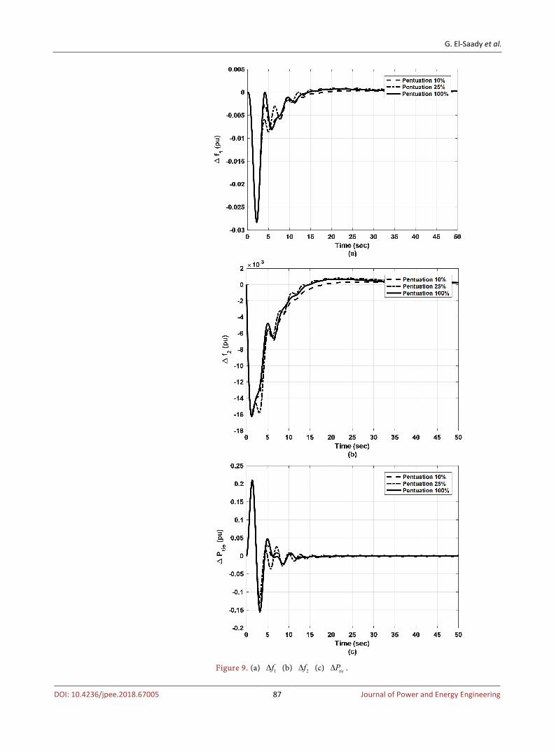
4.3. Disturbance Area 2 (Pen 10%, 25%, 100%)
Figure 9 shows a) 1f∆ b) 2f∆ c) tieP∆ with different wind Penetration with disturbance at area 2.
4.4. Change Time Constant Hydraulic (±10%, ±25%)
Figure 10 shows (a) 1f∆ (b) 2f∆ (c) tieP∆ with change ±10% time constant of hydraulic power plant with disturbance at area 2.
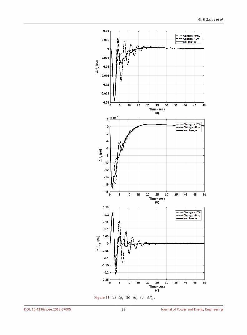
Figure 11 shows (a) 1f∆ (b) 2f∆ (c) tieP∆ with change ±25% of hydraulic power plant with disturbance at area 2.
5. Conclusion
In this paper, MO-GA optimization algorithm has been investigated for optimal LFC in multi-area interconnected power systems. The proposed approach is ap-plied to obtain the optimal PID controller parameters to solve frequency regula-tion problem. A comparative study between the systems with wind turbine and without wind turbine scheme is carried out in this work. The test systems have been simulated for step load disturbance in multi-area. The results are compared with the systems without any renewable energy. Among all the responses and results obtained, it is observed that adding wind turbines parallel with hydraulic give the best performances, achieving good response and stability with minimum error or disturbance, and are better in terms of rise time, settling time, oscillations and overshoot for both frequency and tie-line power. From the qualitative and
G. El-Saady et al.
DOI: 10.4236/jpee.2018.67005 86 Journal of Power and Energy Engineering
Figure 8. (a) 1f∆ (b) 2f∆ (c) tieP∆ .
G. El-Saady et al.
DOI: 10.4236/jpee.2018.67005 87 Journal of Power and Energy Engineering
Figure 9. (a) 1f∆ (b) 2f∆ (c) tieP∆ .

G. El-Saady et al.
DOI: 10.4236/jpee.2018.67005 88 Journal of Power and Energy Engineering
Figure 10. (a) 1f∆ (b) 2f∆ (c) tieP∆ .
G. El-Saady et al.
DOI: 10.4236/jpee.2018.67005 89 Journal of Power and Energy Engineering
Figure 11. (a) 1f∆ (b) 2f∆ (c) tieP∆ .
G. El-Saady et al.
DOI: 10.4236/jpee.2018.67005 90 Journal of Power and Energy Engineering
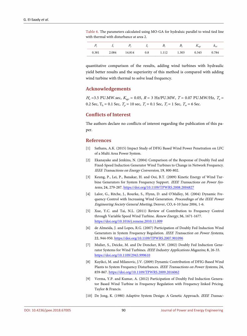
Table 6. The parameters calculated using MO-GA for hydraluic parallel to wind tied line with thermal with disturbance at area 2.
P1 I1 P2 I2 B1 B2 Kwp kwi
0.381 2.084 14.814 0.8 1.112 1.303 0.345 0.784
quantitative comparison of the results, adding wind turbines with hydraulic yield better results and the superiority of this method is compared with adding wind turbine with thermal to solve load frequency.
Acknowledgements
He =3.5 PU.MW.sec, Kagc = 0.05, R = 3 Hz/PU.MW, T = 0.07 PU.MW/Hz, Ta = 0.2 Sec, Th = 0.1 Sec, Tp = 10 sec, Tr = 0.1 Sec, Tt = 1 Sec, Tw = 6 Sec.
Conflicts of Interest
The authors declare no conflicts of interest regarding the publication of this pa-per.
References [1] Sathans, A.K. (2015) Impact Study of DFIG Based Wind Power Penetration on LFC
of a Multi Area Power System.
[2] Ekanayake and Jenkins, N. (2004) Comparison of the Response of Doubly Fed and Fixed-Speed Induction Generator Wind Turbines to Change in Network Frequency. IEEE Transactions on Energy Conversion, 19, 800-802.
[3] Keung, P., Lei, P., Banakar, H. and Ooi, B.T. (2009) Kinetic Energy of Wind Tur-bine Generators for System Frequency Support. IEEE Transactions on Power Sys-tems, 24, 279-287. https://doi.org/10.1109/TPWRS.2008.2004827
[4] Lalor, G., Ritche, J., Rourke, S., Flynn, D. and O’Malley, M. (2004) Dynamic Fre-quency Control with Increasing Wind Generation. Proceedings of the IEEE Power Engineering Society General Meeting, Denver, CO, 6-10 June 2004, 1-6.
[5] Xue, Y.C. and Tai, N.L. (2011) Review of Contribution to Frequency Control through Variable Speed Wind Turbine. Renew Energy, 36, 1671-1677. https://doi.org/10.1016/j.renene.2010.11.009
[6] de Almeida, J. and Lopes, R.G. (2007) Participation of Doubly Fed Induction Wind Generators in System Frequency Regulation. IEEE Transaction on Power Systems, 22, 944-950. https://doi.org/10.1109/TPWRS.2007.901096
[7] Mulier, S., Deicke, M. and De Doncker, R.W. (2002) Doubly Fed Induction Gene-rator Systems for Wind Turbines. IEEE Industry Applications Magazine, 8, 26-33. https://doi.org/10.1109/2943.999610
[8] Kayikci, M. and Milanovic, J.V. (2009) Dynamic Contribution of DFIG-Based Wind Plants to System Frequency Disturbances. IEEE Transactions on Power Systems, 24, 859-867. https://doi.org/10.1109/TPWRS.2009.2016062
[9] Verma, Y.P. and Kumar, A. (2012) Participation of Doubly Fed Induction Genera-tor Based Wind Turbine in Frequency Regulation with Frequency linked Pricing. Taylor & Francis.
[10] De Jong, K. (1980) Adaptive System Design: A Genetic Approach. IEEE Transac-

G. El-Saady et al.
DOI: 10.4236/jpee.2018.67005 91 Journal of Power and Energy Engineering
tions on Systems, Man, and Cybernetics, 10, 1566-1574. https://doi.org/10.1109/TSMC.1980.4308561
[11] Schultz, W.C. and Rideout, V.C. (1961) Control System Performance Measures: Past, Present and Future. IEEE Transactions on Automatic Control, AC-6, 22-35. https://doi.org/10.1109/TAC.1961.6429306
[12] Goldberg, D.E. (1989) Genetic Algorithms in Search, Optimization and Machine Learning. Addison-Wesley, Reading, MA.
[13] Fleming, P.J. and Fonseca, C.M. (1993) Genetic Algorithms in Control Systems En-gineering. Research Report No. 470, Department of Automatic Control and Systems Engineering, University of Sheffield, Sheffield, UK.
[14] Whitley, D. (2005) A Genetic Algorithm Tutorial. Computer Science Department, Colorado State University, Colorado, USA.
[15] Haupt, R.L. (2004) Practical Genetic Algorithms. 2nd Edition, John Wiley and Sons, Inc., Publication, Hoboken, New Jersey.
[16] Konak, A., Coit, D.W. and Smith, A.E. (2006) Multi-Objective Optimization Using Genetic Algorithms: A Tutorial. Reliability Engineering and System Safety, 91, 992-1007. https://doi.org/10.1016/j.ress.2005.11.018
[17] Sbalzarini, I.F., Muller, S. and Koumoutsakos, P. (2000) Multi Objective Optimiza-tion Using Evolutionary Algorithms. Center for Turbulence Research Proceedings of the Summer Program, 64-73.
[18] Deb, K., Agrawal, S., Pratap, A. and Meyarivan, T. (2000) A Fast Elitist Non-Dominated Sorting Genetic Algorithm for Multi-Objective Optimization: NSGA-II. Indian Institute of Technology Kanpur, Kanpur, India. (KanGAL Report No. 200001).
[19] Srinivas, N. and Deb, K. (1994) Multi-Objective Optimization Using Non-Dominated Sorting in Genetic Algorithms. IEEE Transactions on Evolutionary Computation, 2, 221-248.
[20] Deb, K., Pratap, A., Agarwal, S. and Meyarivan, T. (2002) A Fast Elitist Multi-Objective Genetic Algorithm: NSGA-II. IEEE Transactions on Evolutionary Computation, 6, 182-197. https://doi.org/10.1109/4235.996017
[21] Rani, M.R., et al. (2012) Multi-Objective Optimization for PID Controller Tuning Using the Global Ranking Genetic Algorithm. International Journal of Innovative Computing, Information and Control, 8, 269-284.