phyygsical modeling for the evaluation of the seismic ... · • transversal seismic behavior and...
TRANSCRIPT

SERIES Workshop “Role of research infrastructures in seismic rehabilitation”Istanbul, 8 - 9 February 2012 SERIES Workshop
“Role of research infrastructures in seismic rehabilitation”Istanbul, 8 - 9 February 2012
Physical modeling for the evaluation of the y gseismic behavior of underground structures
TA- SERIES
G. Tsinidis, D. Pitilakis, E. Rovithis , E. Kirtas, A. Anastasiadis
TA SERIES
K. Pitilakis
Aristotle University, Thessaloniki Greece
In cooperatıon wıthp
Unıversıty of Cambrıdge UKIFSTTAR Nantes France
AUTH SDGEE
IFSTTAR Nantes France

SERIES Workshop “Role of research infrastructures in seismic rehabilitation”Istanbul, 8 - 9 February 2012
Underground structures
• Mountain tunnelsSubways
Underground structures
• Subways• Highway tunnels• Shallow and deep metro stationsp• Underground parking stations, commercial centers• Nuclear power plants ducts
• Their seismic design in seismically prone areas is of major importance• Safety - economy• Safety economy
AUTH SDGEE

SERIES Workshop “Role of research infrastructures in seismic rehabilitation”Istanbul, 8 - 9 February 2012
Observed damages in past earthquakesSeismic performance Seismic performance
AUTH SDGEE
SERIES Workshop “Role of research infrastructures in seismic rehabilitation”Istanbul, 8 - 9 February 2012
Observed damages in past earthquakes Observed damages in past earthquakes
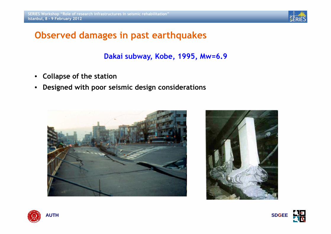
Dakai subway, Kobe, 1995, Mw=6.9
• Collapse of the station• Designed with poor seismic design considerationsg p g
AUTH SDGEE

SERIES Workshop “Role of research infrastructures in seismic rehabilitation”Istanbul, 8 - 9 February 2012
Dakai subway, Kobe, 1995, Mw=6.9y, , ,
• The main cause of collapse is due to the shear and buckling failure of thecentre columns, which were designed and constructed with insufficienttransverse shear reinforcementt a sve se s ea e o ce e t
AUTH SDGEE
Iida et al., 1996, Kawashima, 2000, Hashash et al., 2001

SERIES Workshop “Role of research infrastructures in seismic rehabilitation”Istanbul, 8 - 9 February 2012
Dakai subway, Kobe, 1995, Mw=6.9y, , ,
1.72m 2.19m
Column 10Column 10
AUTH SDGEE

SERIES Workshop “Role of research infrastructures in seismic rehabilitation”Istanbul, 8 - 9 February 2012
Chi Chi earthquake (1999)
spalling
Chi Chi earthquake (1999)
cracks
cracks
spalling
(b) (c)lining cracks
cracks
kl h d ff b cracks
cracks
spalling
(d) (e)lining sheared off by
displaced fault(a)
cracks
localspalling
opening
(f) (g)
AUTH SDGEE
(f) (g)Wang et al. (2001)

SERIES Workshop “Role of research infrastructures in seismic rehabilitation”Istanbul, 8 - 9 February 2012
Kocaeli earthquake (1999)Kocaeli earthquake (1999)• Circular tunnel – failure during construction
ΗΕΒ
03 ‐ 0.4 m
Detail
0.3
AUTH SDGEE
Kontoe et al. (2008)

SERIES Workshop “Role of research infrastructures in seismic rehabilitation”Istanbul, 8 - 9 February 2012
Seismic behavior
• Seismic behavior of underground structures is substantially different fromaboveground structures
• Imposed seismic ground deformations rather than inertial forces dominate• Imposed seismic ground deformations rather than inertial forces dominatethe structure’s seismic response
1x1 (m)
0m10m
8m 1x1 (m)
ρstr.=2.5t/m³E=29 GPa Mmax=683kNm αmax==0.37gαmax=0.62gMmax=444kNm
‐50m(a)
Vs=200m/secρ=2t/m³ξ=5%
8m
4m
1x1 (m)
ρstr.=2.5t/m³E=29 GPa
αmax=0.20g αmax=0.20g10m
Vs=200m/sec
AUTH SDGEE
(b) ρ=2t/m³ξ=5%

SERIES Workshop “Role of research infrastructures in seismic rehabilitation”Istanbul, 8 - 9 February 2012
Shaking• Shaking• Imposed seismic ground deformations and the relative stiffness or the
stiffness contrast between the structure and surrounding soil, control theoverall seismic behaviour of an underground structure
• Ground failure• The response is also controlled by the imposed permanent ground• The response is also controlled by the imposed permanent ground
deformations and displacements due to:• Liquefaction : Settlements, lateral spreading• Slope failure• Fault movements
• Crucial parameters controlling the soil – structure system behavior:
Soil to structure flexural stiffness (Flexibility ratio)• Soil to structure flexural stiffness (Flexibility ratio)
• Soil – tunnel interface conditions (rough or smooth interface)
AUTH SDGEE

SERIES Workshop “Role of research infrastructures in seismic rehabilitation”Istanbul, 8 - 9 February 2012
Flexibility ratio • Penzien, 2000• Deformations of rectangular cavity
ff s ffτ G γ=
c ffγ βγ= ff
( )c ff sβ γ γ 4 1 v= = −
G
• Stiffness of outside soil, inside soil and lining• Compatibility of deformations
ssoil si
Gk τ H= =
( )il ilk k 3 4v= −( )soilo soil sk k 3 4v
( )stru is s ffΔd Δd 4 1 v γ H+ = −
AUTH SDGEE

SERIES Workshop “Role of research infrastructures in seismic rehabilitation”Istanbul, 8 - 9 February 2012
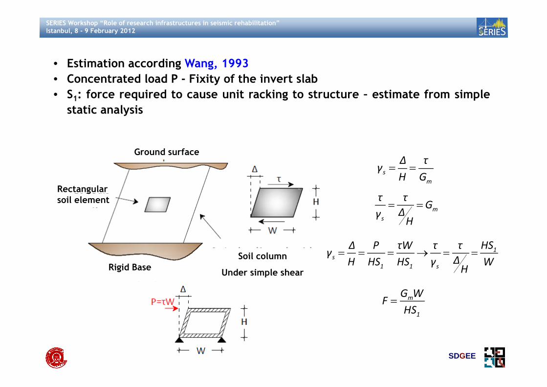
Wang 1993• Wang, 1993• Concentrated load P - Fixity of the invert slab• S1: force required to cause unit racking to structure – estimate from simple
i l istatic analysis
G d f
Rectangular
Ground surface
sm
Δ τγ
Η G= =
gsoil element
ms
τ τG
ΔγΗ
= =
Rigid Base Soil column
Under simple shear
1s
1 1 s
ΗSΔ P τW τ τγ
ΔΗ ΗS ΗS γ WH
= = = → = =
m
1
G WF
ΗS=
AUTH SDGEE

SERIES Workshop “Role of research infrastructures in seismic rehabilitation”Istanbul, 8 - 9 February 2012
Important “open” issuesImportant open issues
• Input motion intensity and characteristics and modeling issuesTransversal seismic behavior and analysis• Transversal seismic behavior and analysis
• Estimation of seismic earth pressures• Estimation of seismic shear stresses along the perimeterg p• Deformation pattern• Estimation of impedance functions• Modeling features (i.e. equivalent static loads, boundaries etc.)
• Longitudinal seismic behavior and analysis• Estimation of the asynchronous seismic motion• Estimation of the asynchronous seismic motion• Estimation of impedance functions• Deformation patterns and modelling
• Several other issues coming from the design and construction point of view• Joints performance, design and construction, in case of segmented
underground structures (e g immersed tunnels)
AUTH SDGEE
underground structures (e.g. immersed tunnels)

SERIES Workshop “Role of research infrastructures in seismic rehabilitation”Istanbul, 8 - 9 February 2012
Important “open” issues – example Important open issues example • Input motion? Shear stresses• Equivalent static forces?• Impedance functions?
h
ground differential displacementbetween surface and bedrock
δxsoils weight + inertia forces
seismic shearstresses
dynamicpressures
dynamicpressures δx
structure'sweight +
pressures pressures
weight +inertia forces
i i dsprings‐impedancefunctionsKx,Ky
seismic shearstresses
bedrock
AUTH SDGEE
bedrock

SERIES Workshop “Role of research infrastructures in seismic rehabilitation”Istanbul, 8 - 9 February 2012
Physical modeling of seismic behavior of underground structures
Short literature review
AUTH SDGEE

SERIES Workshop “Role of research infrastructures in seismic rehabilitation”Istanbul, 8 - 9 February 2012
Physical modeling of seismic behavior of underground Physical modeling of seismic behavior of underground structures
• Few well-documented case histories, lack of comprehensive methodologiesspecific guidelines and seismic code regulations for the seismic design ofunderground structures with the exception maybe of gas and oil pipelines
• Physical modeling and numerical analysis are used to better understand thephysical problem and in particular the soil structure interaction phenomenonphysical problem and in particular the soil-structure interaction phenomenon
• Physical modeling provide quality data under perfectly controlled conditionsfor the validation of the numerical procedures and codes
Indicative examples (a list of references is presented at the end)• Indicative examples (a list of references is presented at the end)
AUTH SDGEE

SERIES Workshop “Role of research infrastructures in seismic rehabilitation”Istanbul, 8 - 9 February 2012
Case 1• Researchers: Bilotta et al., 2009, Lanzano et al., 2010 (ReLUIS project)• Type of structure: Circular tunnels• Type of experiments: dynamic centrifuge tests performed on aluminum
tunnel models embedded in dry sand under 80g, to study the affection ofburial depth on the seismic behavior and mainly to produce data for thevalidation of the design methods (uncoupled and coupled methods)
• Tests conducted at the Centrifuge facility of the Schofield Center in alaminar boxlaminar box
AUTH SDGEE
SERIES Workshop “Role of research infrastructures in seismic rehabilitation”Istanbul, 8 - 9 February 2012
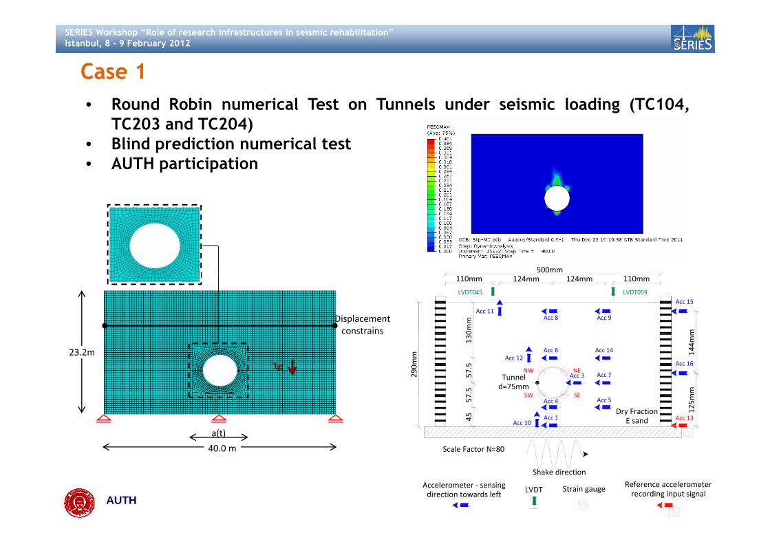
Case 1• Round Robin numerical Test on Tunnels under seismic loading (TC104,
TC203 and TC204)• Blind prediction numerical testBlind prediction numerical test• AUTH participation
500mm
Displacement constrains
Acc 11Acc 15
Acc 8 Acc 9
LVDT045 LVDT059
124mm124mm110mm500mm
110mm
m0mm
23.2m1g
constrains
Acc 16
SW SE
NW NEAcc 7
Acc 14Acc 6Acc 12
Acc 3Tunneld=75mm
290m
m
mm
144m
m
130
57.5
7.5
40.0 m
a(t)
Scale Factor N=80
Acc 13Acc 1
Acc 4SW SE
Acc 5
Acc 10
Dry FractionE sand
125m57
45
AUTH SDGEE
Shake direction
Accelerometer ‐ sensingdirection towards left LVDT Strain gauge Reference accelerometer
recording input signal

SERIES Workshop “Role of research infrastructures in seismic rehabilitation”Istanbul, 8 - 9 February 2012
Case 2Case 2• Researchers: Cilingir & Madabhushi (2010a, 2010b, 2011)• Type of structure: Square, Circular tunnels• Type of experiments: dynamic centrifuge tests performed on aluminum
tunnel models embedded in dry sand under 50g, to study the affection ofthe input motion characteristics and of the burial depth of the tunnels onp pthe seismic behavior
• Tests conducted at the Centrifuge facility of the Schofield Center at theUniversity of Cambridge UK using a Rigid box with a windowUniversity of Cambridge UK using a Rigid box with a window
AUTH SDGEE

SERIES Workshop “Role of research infrastructures in seismic rehabilitation”Istanbul, 8 - 9 February 2012
Case 3• Researchers: Shibayama et al., 2010• Type of structure: Urban mountain type tunnels• Type of experiments: pseudo-static centrifuge tests performed on
aluminum tunnel models embedded in dry sand, to study the effect ofburial depth and the connection of the invert slab with the tunnel lining
Welded model
AUTH SDGEE
Non-welded model

SERIES Workshop “Role of research infrastructures in seismic rehabilitation”Istanbul, 8 - 9 February 2012
Case 4• Researchers: Chou et al., 2010, Kutter et al., 2008, Travasarou & Chacko,
2008, Travasarou, 2010T f t t : i d t l t fit h k f th i ti g BART• Type of structure: immersed tunnel, retrofit check of the existing BARTsystem
• Type of experiments: 2 dynamic centrifuge tests performed on PVC tunnelmodels, under 40g, to evaluate the potentially uplift of the BART tubecaused by liquefaction (UC Davis USA)
AUTH SDGEE

SERIES Workshop “Role of research infrastructures in seismic rehabilitation”Istanbul, 8 - 9 February 2012
Case 5• Researchers: Chen et al., 2010• Type of structure: Rectangular utility tunnel• Type of experiments: 46 shaking table tests performed on RC models (one
jointless and one with 2 construction joints) embedded in unsaturatedsand to study the effect of the non-uniform ground motion along thealignment of a utility tunnel
• Sensors to measure slippage at the interface, displacement and rotationat the jointsat the joints
AUTH SDGEE

SERIES Workshop “Role of research infrastructures in seismic rehabilitation”Istanbul, 8 - 9 February 2012
Main remarksMain remarks
• For horizontal shaking appearance of vertical acceleration components(i.e. Yukio et al., 2001)
• Physical modeling can help to understand the uplift behavior of immersedtunnels during liquefaction, validate the efficiency of the countermeasuretunnels during liquefaction, validate the efficiency of the countermeasureretrofit techniques and validate the numerical models (i.e. Adalier et al.,2003, Chou et al., 2010 etc.)
• Kinematic loads (ground strains) are more important than inertial forces• Kinematic loads (ground strains) are more important than inertial forces(i.e. Iwaga et al., 2006)
• Internal forces, in case of flexible embedded structures; Three distinctivet b d l t i t t f ll i b t d t tstages are observed namely a transient stage following by steady state
circles and finally a post-earthquake residual stage, (i.e. Bilotta et al, 2010,Lanzano, 2009, Cilingir & Madabhushi, 2010a, 2010b, 2011)
AUTH SDGEE
SERIES Workshop “Role of research infrastructures in seismic rehabilitation”Istanbul, 8 - 9 February 2012
• Shear stresses around the perimeter of an underground structure: It isvery difficult to be measured accurately. Their values depend on severaly y pfactors (intensity of the input motion, rugosity of the soil lining interface,measuring equipment etc) (Tohda et al, 2010).
• Flexible tunnels (square or circular) tend to deform inward (i e Cilingir &• Flexible tunnels (square or circular) tend to deform inward (i.e. Cilingir &Madabhushi, 2010a, 2010b, 2011). Except for racking or ovalingdeformations
• Non-uniform earthquake excitations produce higher intensities comparedto uniform ones (i.e. Chen et al., 2010)
• Non-uniform earthquake excitations can lead to important differentialq pdisplacements and rotation of the joints in case of segmented structures(i.e. Chen et al., 2010)
AUTH SDGEE

SERIES Workshop “Role of research infrastructures in seismic rehabilitation”Istanbul, 8 - 9 February 2012
• Questions on crucial “open” issues are not fully answered, namely:
• Input motion (characteristics, asynchronous motion)?• Seismic earth pressures on the side walls?
Seismic shear stresses around the embedded structure perimeter?• Seismic shear stresses around the embedded structure perimeter?• Deformation patterns• Impedance functions for underground structures?p g• Effect of backfill material on the seismic behavior of underground
structures?J i t f d i t d ig ?• Joints performance and appropriate design?
AUTH SDGEE

SERIES Workshop “Role of research infrastructures in seismic rehabilitation”Istanbul, 8 - 9 February 2012
AUTH ongoing research projects on the seismic behavior of rectangular embedded structureswith reference to physical modelling in the
framework of SERIES
AUTH SDGEE

SERIES Workshop “Role of research infrastructures in seismic rehabilitation”Istanbul, 8 - 9 February 2012
Introduction Introduction • Further experimental and numerical study deemed to be necessary,
especially in case of rectangular embedded structures, to answer the “open”d h dquestions and improve the seismic design
• Two relevant research projects are running within the Transnational Accesstask of SERIES, titled:
• “Investigation of the seismic behavior of shallow rectangularunderground structures in soft soils using centrifuge experiments”
• “Investigation of several aspects affecting the seismic behavior ofshallow rectangular underground structures in soft soils”
• The first program is running at the centrifuge facility of IFSTTAR in Nantes,France, whereas the second program is running at the centrifuge facility ofthe Schofield Center at the University of Cambridge, UK
• Centrifuge testing of rectangular embedded structures in dry or saturated
AUTH SDGEE
g g g ysands submitted to simple sine waves or real recordings

SERIES Workshop “Role of research infrastructures in seismic rehabilitation”Istanbul, 8 - 9 February 2012
• Main objectives:
• Study the influence of the relative flexibility ratios on the driftdisplacement
• Study the seismic earth pressures distribution along the side-walls
• Study the seismic shear stresses distribution and magnitude along they g gperimeter of underground structures
• Estimate proper impedance functions for underground structures toEstimate proper impedance functions for underground structures tomodel kinematic and inertial soil structure interaction effects
• Study the effect of backfill material (e.g. gravel), on the seismicStudy the effect of backfill material (e.g. gravel), on the seismicbehavior of an underground structure
AUTH SDGEE

SERIES Workshop “Role of research infrastructures in seismic rehabilitation”Istanbul, 8 - 9 February 2012
“Investigation of the seismic behavior of shallow rectangular underground structures in
soft soils using centrifuge experiments”
Centrifuge facility of IFSTTAR, Nantes, France
AUTH SDGEE

SERIES Workshop “Role of research infrastructures in seismic rehabilitation”Istanbul, 8 - 9 February 2012
General descriptionGeneral description• Centrifuge tests on rectangular tunnel models, embedded in saturated or dry
sand under a centrifugal acceleration of 40g will be carried out at thet if f ilit f IFSTTAR i N t Fcentrifuge facility of IFSTTAR in Nantes, France
54mm or 47mm 400mm360mm
326mm
Section A‐A ‐ Soil instrumentation
Model
mm Α Α
Model
m10
0mm
180mm
15mm
50mm
10mm180mm
340m
Dry FontainebleauSand (Dr=70%)
320m
m
Dry FontainebleauSand (Dr=70%)
360m
m
30mm
130m
m
Scale Factor N=40Shake direction
800mm
1Accelerometer ‐ sensingdirection towards left
Pore pressuresensor
Reference accelerometerrecording input signal
AUTH SDGEE

SERIES Workshop “Role of research infrastructures in seismic rehabilitation”Istanbul, 8 - 9 February 2012
• Objectives:j• Seismic earth pressures distribution along the side-walls• Seismic shear stresses distribution along the perimeter• Impedance functionsImpedance functions
• Reduction factor N=40• 2 models: flexible model rigid model (2017 A aluminium alloy)• 2 models: flexible model, rigid model (2017 A aluminium alloy)• 2 levels of rugosity (smooth interface: , rough interface: )• Dry / saturated Fontainebleau sand NE34 (Dr=70%)
Real recordings of increasing amplitude (+ sine wavelets)
aluminiumδ δ= δ φ=
• Real recordings of increasing amplitude (+ sine wavelets)• 7 tests + 1 free field test
Model 1 Model 2
m 1 5m
47mmModel 1
m
Model 2
54mm
mm
5
m
6mm 1.5mm
1.5mm50mm
50mm 6m
5mm
m
5mm
AUTH SDGEE
6mm
6mm

SERIES Workshop “Role of research infrastructures in seismic rehabilitation”Istanbul, 8 - 9 February 2012
• Estimation of the flexibility ratio for the proposed model sections Estimation of the flexibility ratio for the proposed model sections • Takatori, 1995 (scaled to 0.05g (EQ1), 0.10g (EQ2), 0.15g (EQ3), 0.20g (EQ4),
0.30g (EQ5))
Ri id t lFlexible tunnel
12
14
16 Rigid tunnel
1
1.2
8
10
12
bility ratio
0.6
0.8
bility ratio
4
6
flexib
Saturated sandDry sand 0.2
0.4flexib
0
2
Initial EQ1 EQ2 EQ3 EQ4 EQ5
0
Initial EQ1 EQ2 EQ3 EQ4 EQ5
2mG HW
F ψ12 EI
⎛ ⎞= ⎜ ⎟
⎝ ⎠
6mm 1.5mm
mm
47mm
0mm
54mm
6mm
5
5mm
AUTH SDGEE
R12 EI⎜ ⎟⎝ ⎠
6mm
6
1.5mm50 50 5mm
6mm
SERIES Workshop “Role of research infrastructures in seismic rehabilitation”Istanbul, 8 - 9 February 2012
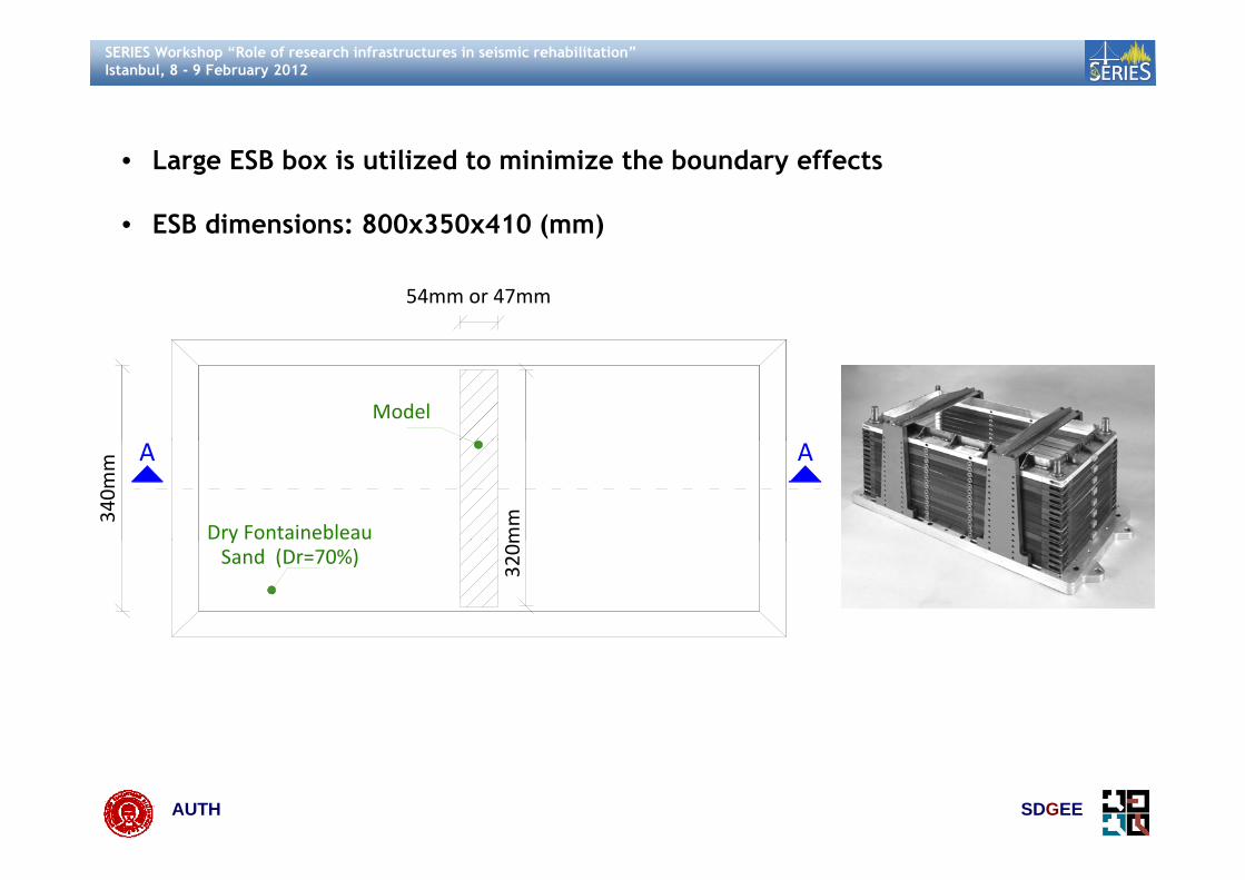
• Large ESB box is utilized to minimize the boundary effects
• ESB dimensions: 800x350x410 (mm)
54mm or 47mm
Model
340m
m Α Α
Dry Fontainebleau mm
ySand (Dr=70%)
320m
AUTH SDGEE

SERIES Workshop “Role of research infrastructures in seismic rehabilitation”Istanbul, 8 - 9 February 2012
• Special connection of the tunnel models ends to the laminar box to avoid any limitation of the models deformation that can affect the plane strain behavior
• 10mm thick Teflon plate + waterproof knob + aluminium plate glued on the knob
54mm or 47mm
Model
m Α Α
340m
m
Dry FontainebleauSand (Dr=70%)
320m
m
AUTH SDGEE

SERIES Workshop “Role of research infrastructures in seismic rehabilitation”Istanbul, 8 - 9 February 2012
Model configuration instrumentation scheme • Model configuration – instrumentation scheme
360mm
Section A‐A ‐ Soil instrumentation
Model
m
400mm360mm
326mm180mm
mm
10mm180mm
mm
0mm
100m
m15mm
50m
Dry FontainebleauSand (Dr=70%)
360m
30mm
130
Shake direction800mm
1
Scale Factor N=40
AUTH SDGEE
Accelerometer ‐ sensingdirection towards left
Pore pressuresensor
Reference accelerometerrecording input signal

SERIES Workshop “Role of research infrastructures in seismic rehabilitation”Istanbul, 8 - 9 February 2012
Check of the plane strain conditions with diagonal extensonmeters at three • Check of the plane strain conditions with diagonal extensonmeters at three sections of the model (2 ends, middle)
Strain ga gegauge
AUTH SDGEE

SERIES Workshop “Role of research infrastructures in seismic rehabilitation”Istanbul, 8 - 9 February 2012
• System of extensometers to measure the lateral displacement profile of the walls of the culvert due to the soil pressure
• At each level of the cross section a 2 tooth fork equipped with strain gaugeswill give the lateral displacement of the culvert wall at this level
Distance of walls to be measuredDistance of walls to be measured
2 independant extensometers
1 mm max.
Holes in the fork for fixingOn the culvert bottom slab Piled extensometer systems
AUTH SDGEE
On the culvert bottom slab Piled extensometer systems
SERIES Workshop “Role of research infrastructures in seismic rehabilitation”Istanbul, 8 - 9 February 2012
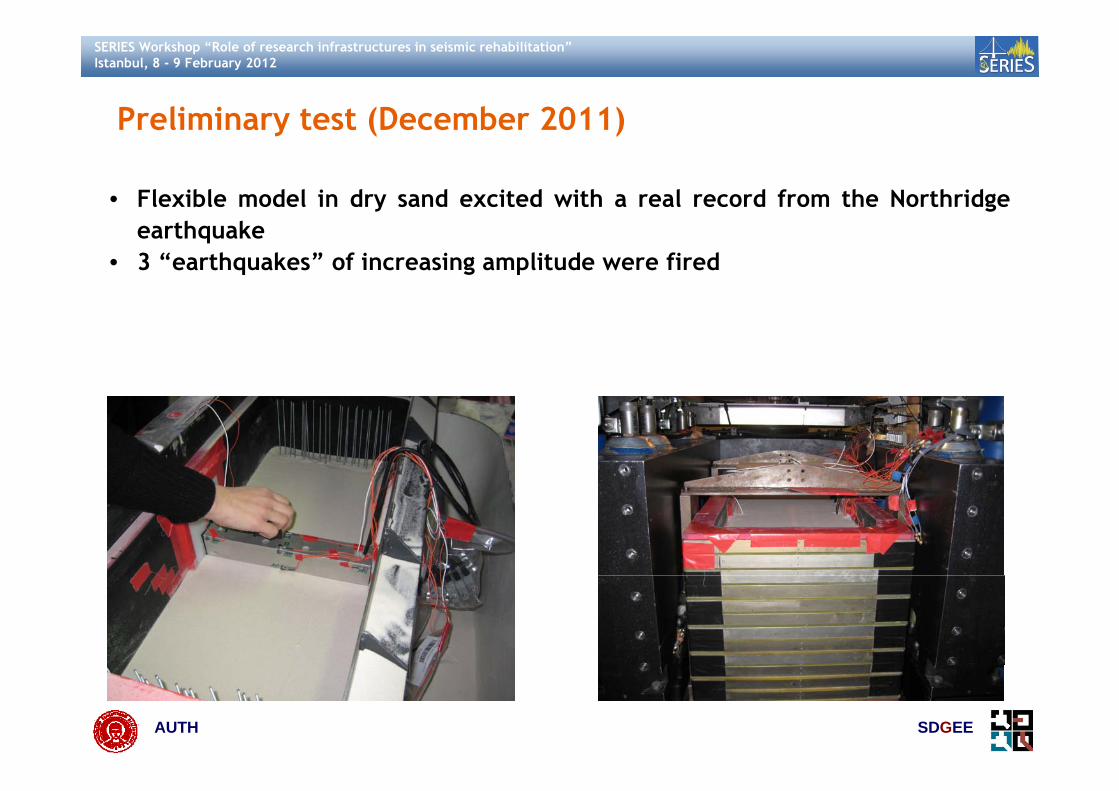
Preliminary test (December 2011)
• Flexible model in dry sand excited with a real record from the Northridge
Preliminary test (December 2011)
earthquake• 3 “earthquakes” of increasing amplitude were fired
AUTH SDGEE

SERIES Workshop “Role of research infrastructures in seismic rehabilitation”Istanbul, 8 - 9 February 2012
Preliminary numerical analysis Preliminary numerical analysis • Preliminary numerical analysis can be used to optimize the experimental set
up giving a general idea of the expected performanceN i l i l ti f th fl ibl t l d l i d d i d l l• Numerical simulation of the flexible tunnel model in dry sand in model scaleusing the ABAQUS
Tunnel: Linear elastic
3
E 70GPa
γ 27.17 kN m
=
=
Tunnel: Linear elastic
Interface:Coulomb friction μ=0.4
Hard contact(no separation is allowed)360mm (no separation is allowed)
PIN CONSTRAIN
Soil: Mohr Co lomb
40g
3
sm
γ 16.3kN m
V 234m s
=≈
Soil: Mohr Coulomb
AUTH SDGEE
800mma(t)
gο οφ=32 ,ψ 4
c 0.001MPa
D 5%
===

SERIES Workshop “Role of research infrastructures in seismic rehabilitation”Istanbul, 8 - 9 February 2012
• Dynamic Step• Dynamic Step• Horizontal acceleration – EQ2 (t=0.43s)
AUTH SDGEE

SERIES Workshop “Role of research infrastructures in seismic rehabilitation”Istanbul, 8 - 9 February 2012
• Dynamic Stepy p• Residual pressures after strong excitations • Larger pressures at joints (corners)
60
70
40
50
σ (kPa)
20
30
8 4
mσ 45kPa*≈
8
8.2
8.4
mσ 7.5kPa*≈
7 4
7.6
7.8
σ (kPa)
AUTH SDGEE7
7.2
7.4*Mean values during the test

SERIES Workshop “Role of research infrastructures in seismic rehabilitation”Istanbul, 8 - 9 February 2012
Dynamic Step• Dynamic Step• Shear stresses at maximum racking distortion
Maximum value
AUTH SDGEE

SERIES Workshop “Role of research infrastructures in seismic rehabilitation”Istanbul, 8 - 9 February 2012
Dynamic Step• Dynamic Step• Shear stresses at maximum racking distortion vs. Mohr Coulomb limit stress
Shear stress along the tunnel perimeter (time step @ max. racking distortion)
0 0.04475 0.0895 0.13425 0.179A B C D A
D C
10‐505
D C
‐25‐20‐15‐10
S12 (kPa) A
x=0
B
‐45‐40‐35‐30
Shear strainMohr‐Coulomb limit stress
Maximum value
45 Mohr‐Coulomb limit stress
{ }max stat .,yy dyn.,yySlabs : σ σ σ tanφ= + ×
AUTH SDGEE
{ }{ }max stat .,xx dyn.,xx
ο
Side walls , σ σ σ tanφ
φ=32
= + ×

SERIES Workshop “Role of research infrastructures in seismic rehabilitation”Istanbul, 8 - 9 February 2012
“Investigation of several aspects affecting the i i b h i f h ll t g l seismic behavior of shallow rectangular underground structures in soft soils”
Centrifuge facility of Schofield Center, University of Cambridge, UK y g ,
AUTH SDGEE

SERIES Workshop “Role of research infrastructures in seismic rehabilitation”Istanbul, 8 - 9 February 2012
General description General description • Centrifuge tests on square tunnels embedded in dry Hostun S32 sand, under
centrifugal acceleration of 50g, performed at the centrifuge facility of the S h fi ld C t f th U i it f C b idSchofield Center of the University of Cambridge
100mm
mm
Tunnel
Plate t=10mm
220m Α
Tunnel
Sand
Α
60mm
m
673mm
427m
m
370m
m
100m
m
Tunnel
m
286.5mm 100mm 286.5mmm
60mm
100m
m
Tunnel
Sand ‐ Dr=90%
210m
673mm
Sand ‐ Dr=50%
370m
m
427m
10m
m
Sand ‐ Dr=50%
40mm
286.5mm 100mm 286.5mm
Sand Dr=90%
AUTH SDGEE
673mm
Scale Factor N=50Shake direction
170
673mm
SERIES Workshop “Role of research infrastructures in seismic rehabilitation”Istanbul, 8 - 9 February 2012
• Objectives:• Influence of the relative flexibility ratios on the drift displacements• Effect of the flexibility ratio on the seismic earth pressures and the
seismic shear stresses distribution along the perimeter• Effect of the backfill material, on the seismic behavior of an
underground structureg
• Reduction factor N=50
• The tests are performing in the large ESB box (673x427x253 (mm))
• 2 tunnel models (BS5251-H24 Aluminum alloy):• 2 tunnel models (BS5251-H24 Aluminum alloy):• flexible model: 100 x 100 x 220 (mm), thickness 0.5mm• rigid model: 100 x 100 x 220 (mm), thickness: 2mm
• Teflon plates, 110 x 110 x 10 (mm) in dimensions, bonded with each otherwith a large screw, were used to avoid the entrance of sand in the tunnel
d l d h
AUTH SDGEE
model during the test

SERIES Workshop “Role of research infrastructures in seismic rehabilitation”Istanbul, 8 - 9 February 2012
• A two layered soil deposit will be used to study the effect of the commonlyused backfill material on the seismic behavior
• Sine wavelets of increasing amplitude
• 3 tests• 3 tests
• Records in terms of:• Accelerations in several points in the soil and on the model using• Accelerations in several points in the soil and on the model, using
accelerometers• Earth pressures at two locations on the one side wall of the structure,
i th llusing earth pressure cells• Settlement of the soil surface at two locations, using LVDTs• Movement of the tunnel (i.e. rocking), using potensiometers• Strains on the model (axial and bending) using full bridge strain gauges
AUTH SDGEE
SERIES Workshop “Role of research infrastructures in seismic rehabilitation”Istanbul, 8 - 9 February 2012
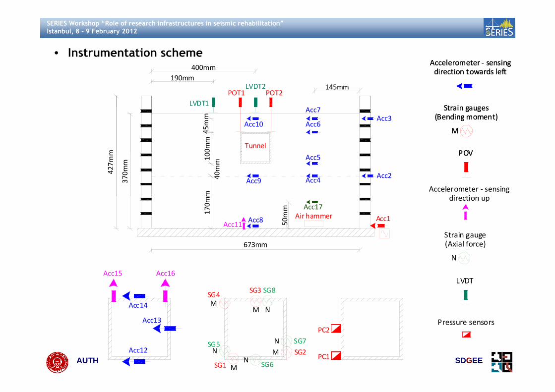
• Instrumentation scheme Accelerometer sensingAccelerometer sensing
LVDT1
LVDT2 145mm190mm
POT1 POT2
400mmAccelerometer ‐ sensingdirection towards left
Strain gauges
Accelerometer ‐ sensingdirection towards left
Strain gaugesm
Tunnel
Acc10Acc3
Acc6
Acc7
0mm
45mm
Strain gauges(Bending moment)
M
POV
Strain gauges(Bending moment)
M
POV
370m
m
427m
m Acc5
Acc2Acc4Acc9
m40mm100 POV
Accelerometer ‐ sensingdi ti
POV
Acc1Acc8
Acc17Air hammer17
0mm
50mm
Acc11Strain gauge
direction up
673mm
Acc16Acc15
(Axial force)
N
LVDT
MM
N
PC2
SG3SG4
SG8
Acc13
Acc14
Pressure sensors
AUTH SDGEEM
MNN
N PC1
PC2
SG1
SG2SG5
SG6
SG7Acc12

SERIES Workshop “Role of research infrastructures in seismic rehabilitation”Istanbul, 8 - 9 February 2012
• 2 flights per test• 1 flight: main test using CDAQS (sampling rate: 4kHz)• 2 flight: Air hammer testing using Dasylab (sampling rate: 50kHz) to
estimate the Vs profile
AUTH SDGEE

SERIES Workshop “Role of research infrastructures in seismic rehabilitation”Istanbul, 8 - 9 February 2012
• Model configuration for the first test (performed on 26-27/1/2012)100mm
mm
Tunnel
Plate t=10mm
220
Sand
Α
673mm
m
60mm
00mm
Tunnel
427m
m
370m
m
1010
mm
286.5mm 100mm 286.5mm21
673mm
Sand ‐ Dr=50%
AUTH SDGEE
Scale Factor N=50Shake direction

SERIES Workshop “Role of research infrastructures in seismic rehabilitation”Istanbul, 8 - 9 February 2012
1st test • Relatively rigid model (t=2mm)
1 test
AUTH SDGEE
SERIES Workshop “Role of research infrastructures in seismic rehabilitation”Istanbul, 8 - 9 February 2012
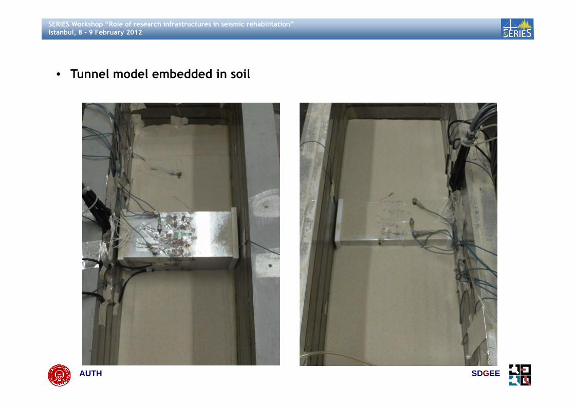
• Tunnel model embedded in soil
AUTH SDGEE

SERIES Workshop “Role of research infrastructures in seismic rehabilitation”Istanbul, 8 - 9 February 2012
• Final model
AUTH SDGEE

SERIES Workshop “Role of research infrastructures in seismic rehabilitation”Istanbul, 8 - 9 February 2012
• Four sine wavelets of increasing amplitude and same frequency were fired in • Four sine wavelets of increasing amplitude and same frequency were fired in a row, having maximum amplitudes: 0.2g, 0.26g, 0.32g, 0.38g respectively
• Unfortunately the strain gauges did not record something measurable• Unfortunately, the strain gauges did not record something measurablebecause the model was rather rigid and the strains quite small to bemeasured
• Indicative results • Acceleration at base of the model – EQ1
Input motion ‐ EQ1 (prototype scale) ‐ filtered 0.1‐10Hz
0 15
0.2
0.25Input motion ‐ EQ1 Fourier
0 8
1
0
0.05
0.1
0.15
A(g)
0 4
0.6
0.8
A(g)
0 2
‐0.15
‐0.1
‐0.05 0 10 20 30 40 50
A
max: 0.197gmin: ‐0.22g 0
0.2
0.4
AUTH SDGEE
‐0.25
‐0.2t(s)
min: 0.22g0 2 4 6 8 10f(Hz)

SERIES Workshop “Role of research infrastructures in seismic rehabilitation”Istanbul, 8 - 9 February 2012
Settlement of the soil surface dynamic part• Settlement of the soil surface – dynamic part• Smaller settlements above the tunnel – rigid structure• ε = 2% !!
Surface settlement (dynamic part)2 Surface settlement (dynamic part)
1
0
1
2
0 1 2 3 4t(s))
190mm400mm
LVDT2LVDT1
‐3
‐2
‐1 0 1 2 3 4t(s)
ment (mm)
Tunnel
‐6
‐5
‐4
settle
LVDT‐2
‐8
‐7 LVDT‐1
AUTH SDGEE

SERIES Workshop “Role of research infrastructures in seismic rehabilitation”Istanbul, 8 - 9 February 2012
• Pressure at the side wall – invert slab joint – EQ4 • Pressure at the side wall invert slab joint EQ4
Earth Pressure (Joint) ‐ Dynamic part40 Earth Pressure (Joint) ‐ Dynamic part40
20
30 PC1
20
30 PC1
10 t(s)
(kPa) 10 t(s)
(kPa)
‐10
0
0 0.2 0.4 0.6 0.8 1
Pressure
‐10
0
0 0.2 0.4 0.6 0.8 1
Pressure
‐20‐20
‐40
‐30Test Mononobe Okabe (dynamic part)
{φ=32ο δ=0ο k =0 462g K =0 74 γ=14kN/m3}‐40
‐30Test Mononobe Okabe (dynamic part)
{φ=32ο δ=0ο k =0 462g K =0 74 γ=14kN/m3}
AUTH SDGEE
{φ=32 , δ=0 , kh=0.462g, KAE=0.74,γ=14kN/m }{φ=32 , δ=0 , kh=0.462g, KAE=0.74,γ=14kN/m }

SERIES Workshop “Role of research infrastructures in seismic rehabilitation”Istanbul, 8 - 9 February 2012
Preliminary numerical analysis Preliminary numerical analysis • Numerical simulation in model scale using the ABAQUS, 2009)
E 70GPa=
Tunnel: Linear elastic
Interface:Perfect bonding
3
E 70GPa
γ 27.0kN m=
Perfect bonding370mm
PIN CONSTRAIN
3
sm
γ 15.4kN m
V 220m s
=≈
Soil: Linear elastic
673mm
a(t)
D 5%=
50g
AUTH SDGEE
SERIES Workshop “Role of research infrastructures in seismic rehabilitation”Istanbul, 8 - 9 February 2012
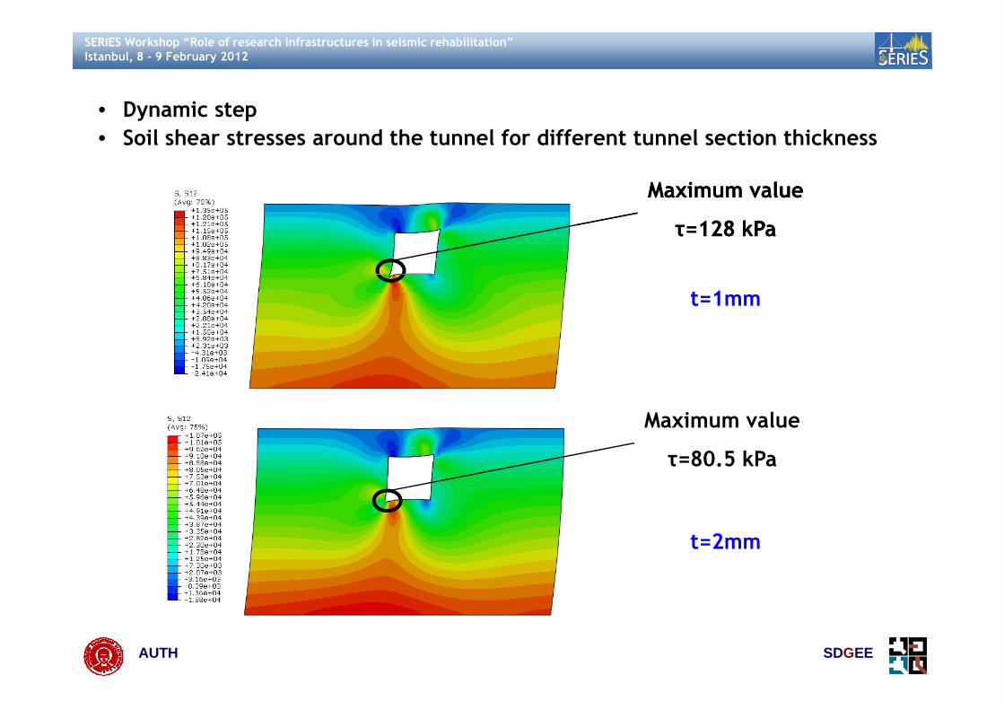
• Dynamic step• Dynamic step• Soil shear stresses around the tunnel for different tunnel section thickness
Maximum valueMaximum valueMaximum value
τ=128 kPa
Maximum value
τ=128 kPa
t=1mm
Maximum value
τ=80.5 kPa
t=2mm
AUTH SDGEE

SERIES Workshop “Role of research infrastructures in seismic rehabilitation”Istanbul, 8 - 9 February 2012
Some important issuescontrolling the tests controlling the tests
AUTH SDGEE

SERIES Workshop “Role of research infrastructures in seismic rehabilitation”Istanbul, 8 - 9 February 2012
Estimation of soil properties• Elastic mechanical properties (E,v) - Gmax profile estimation (G(z))
Estimation of soil properties
• Gmax compatible to the actual test intensities and deformations (i.e. Brennanet al., 2005) – CPT tests before and after each flight or bender elements
• Empirical expressions (i.e. Hardin and Drnevich,1972) may overestimateGmax (i.e. Brennan et al., 2005)
G G‐γ RC or TS testsG‐γ in the centrifugeGmax
G
Estimated by empirical
f l tiGmax,cen
Geff
Geff,cen
Gformulations
Geff,cen
zGeff
AUTH SDGEEγ (%)γeff

SERIES Workshop “Role of research infrastructures in seismic rehabilitation”Istanbul, 8 - 9 February 2012
Flexibility ratio • Penzien, 2000• Deformations of rectangular cavity
ff s ffτ G γ=
c ffγ βγ= ff
( )c ff sβ γ γ 4 1 v= = −
G
• Stiffness of outside soil, inside soil and lining• Compatibility of deformations
ssoil si
Gk τ H= =
( )il ilk k 3 4v= −( )soilo soil sk k 3 4v
( )stru is s ffΔd Δd 4 1 v γ H+ = −
AUTH SDGEE

SERIES Workshop “Role of research infrastructures in seismic rehabilitation”Istanbul, 8 - 9 February 2012
• Depended on the actual soil shear modulus (degraded during the shaking)
• An overestimation of the shear modulus can lead to an overestimation of theflexibility ratio
• Assumptions for the calculation of the flexibility ratio?
• Example: Wang, 1993, Hashash et al., 2001 etc.: static analysis for theExample: Wang, 1993, Hashash et al., 2001 etc.: static analysis for thedetermination of the flexibility ratio assuming fix invert slab. Is the invertslab fixed during the shaking? Deformation modes? Rocking of the tunnel?
mG WF
S H=
1S H
AUTH SDGEE
SERIES Workshop “Role of research infrastructures in seismic rehabilitation”Istanbul, 8 - 9 February 2012
Estimation according Wang 1993• Estimation according Wang, 1993• Concentrated load P - Fixity of the invert slab• S1: force required to cause unit racking to structure – estimate from simple
i l istatic analysis
G d f
Rectangular
Ground surface
sm
Δ τγ
Η G= =
gsoil element
ms
τ τG
ΔγΗ
= =
Rigid Base Soil column
Under simple shear
1s
1 1 s
ΗSΔ P τW τ τγ
ΔΗ ΗS ΗS γ WH
= = = → = =
m
1
G WF
ΗS=
AUTH SDGEE

SERIES Workshop “Role of research infrastructures in seismic rehabilitation”Istanbul, 8 - 9 February 2012
Th k Thank you
AUTH SDGEE

SERIES Workshop “Role of research infrastructures in seismic rehabilitation”Istanbul, 8 - 9 February 2012
References ABAQUS (2009) Analysis User’s Manual – Volumes I - IV – v6.9 [Computer Program], Dassault Systèmes,
SIMULIA Inc, USAAdalier K, Abdoun T, Dobry R, Phillips R, Yang D, Naesgaard E (2003) Centrifuge modelling for seismic
References
retrofit design of an immersed tube tunnel. IJMPG- International Journal of Physical Modelling INGeotechnics 2: 23-35
Bilotta E, Lanzano G, Russo G, Silvestri F, Madabhushi SPG (2009) Seismic analyses of shallow tunnelsby dynamic centrifuge tests and finite elements Proc 17th Int Conf on Soil Mechanics andby dynamic centrifuge tests and finite elements. Proc. 17th Int. Conf on Soil Mechanics andGeotechnical Engineering, Alexandrìa, Egypt
Brennan A J, Thusyanthan N I, Madabhushi S P G (2005) Evaluation of shear modulus and damping indynamic centrifuge tests. Journal of Geotechnical and Geoenvironmental Engineering, ASCE,131(12) 1488 1497131(12), 1488–1497
Cao J, Huang MS (2010) Centrifuge tests on the seismic behavior of a tunnel. Physical Modelling inGeotechnics – Springman, Laue & Seward (eds). Taylor & Francis Group, London, ISBN 978-0-415-59288-8
Chen J, Shi X, Li J (2010) Shaking table test of utility tunnel under non-uniform earthquake waveexcitation. Soil Dynamics and Earthquake Engineering 30: 1400-1416
Chou J C, Kutter B L, Travasarou T, Chacko J M (2010) Centrifuge Modeling of Seismically InducedUplift for the BART Transbay Tube Journal of Geotechnical and Geoenvironmental EngineeringUplift for the BART Transbay Tube. Journal of Geotechnical and Geoenvironmental Engineering,137 (8): 754:765
Cilingir U, Madabhushi SPG (2010a) A model study on the effects of input motion on the seismicbehavior of tunnels. Soil Dynamics and Earthquake Engineering, 31:452-462
Cili i U M d bh hi SPG (2010b) Eff f d h i i f i l l C
AUTH SDGEE
Cilingir U, Madabhushi SPG (2010b) Effect of depth on seismic response of circular tunnels. CanGeotech J, 48 pp 117-127

SERIES Workshop “Role of research infrastructures in seismic rehabilitation”Istanbul, 8 - 9 February 2012
References Cilingir U, Madabhushi SPG (2011) Effect of depth on the seismic response of square tunnels. Soils and
Foundations, 51(3):449-457EERA, Equivalent-linear Earthquake site Response Analysis (Version 2000) [Computer Program Add-in]
References
Available at: http://gees.usc.edu/GEES/Software/EERA2000/Default.htm (Accessed: March 2011)Hardin B O, Drnevich V P(1972) Shear modulus and damping in soils: design equations and curves.
Journal of the Soil Mechanics and Foundations Division 98 (SM7):667–92. ASCHashash YMA Hook JJ Schmidt B Yao JI-C (2001) Seismic design and analysis of undergroundHashash YMA, Hook JJ, Schmidt B, Yao JI C (2001) Seismic design and analysis of underground
structures. Tunnel Undergr Space Technol 16(2):247–293Iida H, Hiroto T, Yoshida N, Iwafuji M (1996) Damage to Daikai subway station. Special issue on
geotechnical aspects of the January 17 1995 Hyogoken–Nanbu earthquake. Soils Found 283–300It K Oh S M t d T (2006) S i i f d d i f d t t tIto K, Ohno S, Matsuda T (2006) Seismic response of underground reinforced concrete structure –
centrifuge model test and its analysis. Journal of Earthquake engineering, JSCE, 27 (12)Izawa J, Kusakabe O, Nagatani H, Yamada T, Ohbo N (2006) Centrifuge modelling on seismic behaviour
of rectangular tunnels, Physical Modelling in Geotechnics ICPMG ’06, pp. 1163-1169Kawasima K (2006) Seismic Analysis of Underground Structures. Journal of Disaster Research 1 (3)Kontoe S, Zdravković L, Potts DM, Menkiti CO (2008) Case study on seismic tunnel response. Canadian
Geotechnical Journal 45(12):1743 – 1764Kutter BL Chou JC Travasarou T (2008) Centrifuge testing of the seismic performance of a submergedKutter BL, Chou JC, Travasarou T (2008) Centrifuge testing of the seismic performance of a submerged
cut and cover tunnel in liquefiable soils. 4th Geotechnical Earthquake Engineering and SoilsDynamics Conference; Proceeding of 4th GEESDC, Sacramento, May, 2008
Lanzano G (2009) Physical and analytical modelling of tunnels under dynami loadings. Ph.D. Thesis,U i i à di N li F d i II
AUTH SDGEE
Università di Napoli Federico II

SERIES Workshop “Role of research infrastructures in seismic rehabilitation”Istanbul, 8 - 9 February 2012
References Lanzano G, Bilotta E, Russo G, Silvestri F, Madabhushi SPG (2009) Experimental assessment of
performance-based methods for the seismic design of circular tunnels. IS-Tokyo 2009Lanzano G, Bilotta E, Russo G, Silvestri F, Madabhushi SPG (2010) Dynamic centrifuge tests on shallow
References
tunnel models in dry sand. VII International Conference on Physical Modelling in Geotechnics,Zurich
Luzhen J, Jun C, Jie L (2010) Seismic response of underground utility tunnels: shaking table testingand FEM analysis Earthq Eng & Eng Vib 9 (4): 555-567and FEM analysis. Earthq Eng & Eng Vib 9 (4): 555 567
Mamoru K, Tadashi K, Matsui J, Akihiro O (2001) Research on streamlining seismic safety evaluation ofunderground reinforced concrete duct-type structures in nuclear power stations – Part 5.Analytical simulation by sophisticated effective stress soil model and simple RC macro model.SMiRT 16 W hi t DC A t 2001SMiRT 16, Washington DC, August 2001
Matsui J, Ohtomo K, Kawai T, Okaichi A (2001) Research on streamlining seismic safety evaluation ofunderground reinforced concrete duct-type structures in nuclear power stations – Part 3.Analytical simulation by RC macro-model and simple soil model. SMiRT 16, Washington DC, August2001
Matsuo T, Ohtomo K, Matsui J, Okaichi A (2001) Research on streamlining seismic safety evaluation ofunderground reinforced concrete duct-type structures in nuclear power stations – Part 4.Analytical simulation by sophisticated RC micro-model and simple soil model SMiRT 16Analytical simulation by sophisticated RC micro-model and simple soil model. SMiRT 16,Washington DC, August 2001
Miyagawa Y, Matsumoto T, Yukio A, Kanaya K (2001) Research on streamlining seismic safety evaluationof underground reinforced concrete duct-type structures in nuclear power stations – Part 6.V ifi i f l i l d d d ili i i f RC d SMiRT 16 W hi DC
AUTH SDGEE
Verification of ultimate load and ductility capacities of RC ducts. SMiRT 16, Washington DC,August 2001
SERIES Workshop “Role of research infrastructures in seismic rehabilitation”Istanbul, 8 - 9 February 2012
References Ohtomo K, Suehiro T, Kawai T, Kanaya K (2001) Research on streamlining seismic safety evaluation of
underground reinforced concrete duct-type structures in nuclear power stations – Part 2.Experimental aspects of laminar shear sand box excitation tests with embedded RC models.
References
SMiRT 16, Washington DC, August 2001Sharma S, Judd WR (1991) Underground opening damage from earthquakes. Eng. Geol. 30, 263-276Shibayama S, Iwaza J, Takahashi A, Kusakabe O (2010) Effect of stress state around tunnel on pseudo-
static response of urban mountain tunnel in sand Joint conference proceedings 7CUEE & 5ICEEstatic response of urban mountain tunnel in sand. Joint conference proceedings 7CUEE & 5ICEE,March 3-5, 2010, Tokyo Institute of Technology, Tokyo, Japan
Shibayama S, Iwaza J, Takahashi A, Takemura J, Kusakabe O (2010) Observed behavior of a tunnel insand subjected to shear deformation in a centrifuge. Soils and Foundations, 50(2): 281-294
T hd J Y hi H Oh i A N k i hi K I Y K H Y W ll R B (2010) C t if d l t tTohda J, Yoshimura H, Ohsugi A, Nakanishi K, Inoue Y, Ko H Y, Wallen R B (2010) Centrifuge model testson the dynamic response of sewer trunk culverts. Modelling in Geotechnics – Springman, Laue &Seward (eds). Taylor & Francis Group, London, ISBN 978-0-415-59288-8
Travasarou T (2010) Insights from the Vulnerability Studies of Liquefaction-Induced Uplift of an( )Immersed Tunnel. Proceedings of the 6th Greek Geotechnical and Geo-enviromental Engineeringconference. Volos, Greece, September 2010 (in Greek)
Travasarou T, Chacko JΜ (2008) Liquefaction-induced uplift mechanics of immersed tunnel. 3d GreekConference of Earthquake Mechanics and Engineering Seismology Athens November 2008 (inConference of Earthquake Mechanics and Engineering Seismology, Athens November 2008 (inGreek)
Wang J N (1993) Seismic design of tunnels: A State of the Art approach. Monograph 7, Parsons,Brinckerhoff, Quade, and Douglas Inc., New York
W WL W TT S JJ Li CH S CR H TH (2001) A f d i i
AUTH SDGEE
Wang WL, Wang TT, Su JJ, Lin CH, Seng CR, Huang TH (2001) Assessment of damage in mountaintunnels due to the Taiwan Chi-Chi earthquake. Tunn Undergr Sp Technol 16:133–150

SERIES Workshop “Role of research infrastructures in seismic rehabilitation”Istanbul, 8 - 9 February 2012
References Yamada T, Nagatani H, Igarashi H, Takahashi A (2002) Centrifuge model tests on circular and
rectangular tunnels subjected to large earthquake-induced deformation. Geotechnical Aspects ofUnderground Construction in Soft Ground, pp: 673-678
References
Yukio A, Tsutomu K, Tatsumi E, Akihiro O (2001) Research on streamlining seismic safety evaluation ofunderground reinforced concrete duct-type structures in nuclear power stations – Part 1. Scope,Objectives and Major Results on the Research. Transactions, SMiRT 16, Washington DC, August20012001
AUTH SDGEE