physics of pacing - csnlc.nhs.uk
TRANSCRIPT

NASPE TRAININGLauren ButlerLancashire & South Cumbria Cardiac Network
PHYSICS OF PACING

Objectives
Pacing stimulationVariations stimulation thresholdSensingLead designPulse generatorsCalculations !!
Strength–Duration Threshold Curve
Stimulation threshold definition
Minimum amount of energy required to produce depolarisation of the myocardium
Exponential relationship exists between pulse duration and stimulus amplitude – strength-duration threshold curve

Strength-Duration Curve
Pulse width (ms)
Threshold (v)
0 0.2 0.4 0.6 0.8 1.0 1.5
5
4
3
2
1
0
Rheobase
chronaxie

Rheobase – smallest voltage amplitude that stimulates the myocardium at an infinitely long pulse durationChronaxie – threshold pulse duration at twice the stimulus amplitude which is twice the rheobase voltageThe chronaxie approximates the lowest stimulation energy (microjoules) required for myocardial deploarisation

Strength-Duration Curve
Pulse width
Threshold
0 0.2 0.4 0.6 0.8 1.0 1.5
5
4
3
2
1
0
Rheobase
chronaxie
Energy (uJ)

Energy
Relationship between Energy, voltage, current and pulse duration Minimum threshold energy (chronaxie)
E = V2 x tR
0.03 0.5 5
voltscurrent
energy
Charge
Units
uC, uJ, v, mA

Constant voltage vs Constant current
All pacing systems – now operate constant voltageStrength duration curves of constant current are similar in shape but the current decline is more gradualHence chronaxie tends to be at a higher pulse width ∴ lowest energy requirements are greater in a constant current device

Constant voltage – programmed to deliver 5 volts, resultant current is unknownWhat is that resultant current dependant upon?Impedance (resistance) of the system V = I x R

Impedance & Resistance
Impedance describes the impediment to current flow of electrons within the entire pacing systemAll factors that contribute to impedance include
Lead conductor resistanceElectrode resistancePolarisation resistance
In constant voltage systems the higher the pacing impedance the lower the current flow

Constant current stimulation !
Calculation to calculate threshold current
I = Ir x (1 + tc/t)
I = threshold current at pulse duration tIr = rheobase currenttc = chronaxie pulse duration

Ideally
Lead conductor material – low resistance (to minimize heat wastage and therefore energy loss)Electrode – high resistance (to minimize current flow)Polarisation – low

Polarisation
Layers of oppositely charged ions that surround the electrode during the pulse stimulus
+
+
+
+
+
+
NA+ & H3O+
IONS

Polarisation Layers
++++++
+
+++
+
+++
- - ---
--
-
----
-negative ions rush towards the positive ion layer
HPO4- &
OH-
Polarisation impedes the movement of charge from electrode to myocardium, thus requiring a greater voltage to stimulate and depolarise myocardial tissue

Polarisation = increase voltage threshold
Polarisation layers build up as the pulse stimulus is present and reaches a peak torwards the end of the stimulusThe longer the stimulus is present the greater the polarisationTo reduce polarisation
Reduce pulse width andUse materials which discourage polarisation
(platinum black, irridium oxide, titanium nitride, activated carbon)

Ideally
Lead conductor material – low resistance (to minimize heat wastage and therefore energy loss)Electrode – high resistance (to minimize current flow)Polarisation – low

Ideal electrode tip
High resistance & ∴ low current drain
Small radius – increases current density and in doing so reduces voltage thresholdLarge surface area – which reduces polarisation
Finally
Polarisation is inversely related to surface areaTo maximize surface area (to reduce polarisation) and minimize the radius (to increase electrode impedance) construction of electrodes consist of a small radius with an irregular surface made out of porous, polarisation reducing material

Ideal electrode tip
Target TipWire filament mesh (lazer bullet holes)Coating microspheresMicroscopic pores
Uneven surface creates hot spots of increased current density whilst keeping the surface area high and the overall radius low

Summary – pacing impedance
Low resistance conductor coilHigh resistance at electrode / myocardial interface
Small radiusHigh surface areaHigh current density
Low polarisationShort pulse widthmaterials

Threshold Variations
Acute changesTypically rises rapidly within the first 24 hours and then gradually increases to a peak at 1 weekover the ensuing 6-8 weeks gradually
declines - reach level – chronic thresholdChronic threshold will be higher than the implantation measurement but less than the peak

Threshold Variations
Magnitude & duration of increase in threshold may be due to
Lead electrode sizeShapeDesignInterface between lead & myocardiumIndividual variation

Stable electrode-myocardial interface
Passive Vs ActiveActive leads have higher threshold at implant but frequently reduces between 15 – 30 minutes post placementDue to hyperacute injury due to advancement of screw
Cortico-Steroid eluting electrodes reduce acute & chronic thresholds (available passive and active leads)

Cellular changesAcute injury to cellular membranesDevelopment myocardial oedemaElectrode surface coated with platelets & fibrinSubsequent release chemotactic factors Acute inflammatory reaction – mononuclear cells & polymorphonuclear leukocytes Following acute response – accelerated cellular injury due to release of proteolytic enzymes & oxygen free radicals by invading macrophagesFinally – fibroblasts within myocardium produce collagen creating fibrous capsule around electrode tip

Fibrous capsule – increase in electrode radius with a possible decrease in electrode surface area Other factors
Increase threshold during sleep, reduces during dayIncreases with hyperglycemia, hypoxia, acute viral illness, after eating, electrolyte fluctuations, drugs

Remember the threshold may also increase at fast pacing rates (short cycle lengths) as the pacing stimulus encroaches into the refractory period of the preceeding beat

Exit Block
Progressive rise in threshold over timeDespite initial satisfactory placementOften occurs in parallel within atria and ventriclesOften recurs with further placement of new leadsSteroid-eluting electrodes prevent exit block in most but not all patients(type steroid – usually 1mg dexamethasone sodium)
Sensing
Wavefront electrical activity approaches electrode – which creates a positive deflection on IEGM as electrode tip becomes positive in relation to negative region of depolarisationAs wavefront passes tip - large negative deflection (called intrinsic deflection)Smaller waveforms pre & post intrinsic deflection due to depolarisation of surrounding myocardium

Ventricular IEGM’s are larger than Atrial IEGM’s – muscle massFourier transformation determines frequency
densityAtrial 80 – 100 HzVentricular 10 – 30 Hz
This allows filter systems to be incorporated into sensing circuits of pacemakers to enhance sensing – myopotentials overlap 10 – 200Hz (Unipolar sensing!)Blanking & refractory periods have helped

Voltage
(ΔV)
IEGM – Slew rate
Slew rate = ΔV/ Δt(Volts/second)
Time(Δt)
R wave amplitude chronic = 85% R wave amplitude acute
Slew rate (V) chronic = 50%–60% slew rate (V) acute

IEGM – slew ratePeak slope of developing EGM Represents maximal rate of change of the electrical potential between the two sensing electrodesWhat should the slew rate be?Slew rate > 0.5 v/sec in both chambersHigh slew = high frequency content = increased chance sensingSlow broad signals (T waves) low slew rate, low frequency content = less likely to be sensed

Polarisation again!
After termination of pacing stimulus – an excess of positive charge surrounds the cathode which gradually decays until neutral – AfterpotentialsAfterpotentials if sensed – inhibition or delay subsequent pacing stimulusAmplitude afterpotentials – related to size and pulse duration of pulse
High PW, High Output, Maximum sensitivivity= not good
Blanking periods reduce this – if not cross talk (highlighted in unipolar sensing systems)

Leading
edgeTrailing
edge
Afterpotential – opposite polarity to stimulus
Constant voltage pulse with leading & trailing edge
Remember – devices with autocapture may be at risk of inappropriate sensing

Acute Vs Chronic sensing
Amplitude & slew rate may abruptly decline within the 1st week post implantAfter 6 – 8 weeks, approach implant levelsActive fixation leads – marked decrease immediately after implant which increases within 20 – 30 minutesCortico-steroid eluting leads have little effect on measurements

Source and Input impedancesSource impedance?The sensing circuit of the system also has impedanceSource impedance – voltage drop that occurs from origin of IEGM to proximal portion of lead
Electrode myocardial resistanceLead conductor resistanceEffects of polarisation

Source & Input impedancesInput Impedance?Impedance of sensing amplifier itselfEGM actually seen by pacer – determined by ratio between sensing amplifier (input impedance) and the lead (source impedance)The bigger the difference/ratio the less attenuation of signal occursInput impedances are large Source impedances – typically 400 - 1500ΩImpedance mismatch – clinically due to insulation or conductor failure – under or oversensing

Lead Design
ComponentsElectrode, conductor, insulator, connector pin
Mechanically stable & flexible in vivoSatisfactory electrical conductive and resistive propertiesDurable insulation with low friction co-efficient but high tensile strengthGood mechanical contact/grip between electrode & myocardium
Sensing circuitry
Incorporates noise reversion circuitsReverts to fixed rate pacing when rate of noise exceeds the noise reversion rateIncorporate Zener diode – protects circuitry from high voltage sources e.g. defibrillation If voltage exceeds zener voltage, the excess is shuntedback through the leads to the myocardium and is dissipated

Electrode
Small radius, large surface areaElectrode shape, surface compositionAlso – biologically inert, resist degradation, do not elicit marked tissue reaction at myocardial interfaceMaterials – reduce polarisation whilst achieving the above
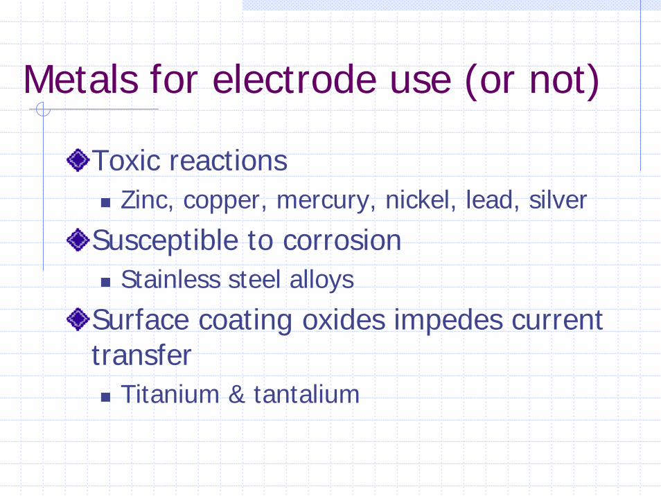
Metals for electrode use (or not)
Toxic reactionsZinc, copper, mercury, nickel, lead, silver
Susceptible to corrosionStainless steel alloys
Surface coating oxides impedes current transfer
Titanium & tantalium

Metals for electrode useIn use today
Platinum-iridiumElgiloy (alloy cobalt, nickel, chromium, molybdenum, iron & manganese) !Platinised titanium coated platinumPyrolytic carbon coated titaniumPyrolytic carbon coated graphiteIridium oxideplatinum
Activated carbon – least susceptible to erosion, the activation process increases surface area and allows for tissue ingrowth *
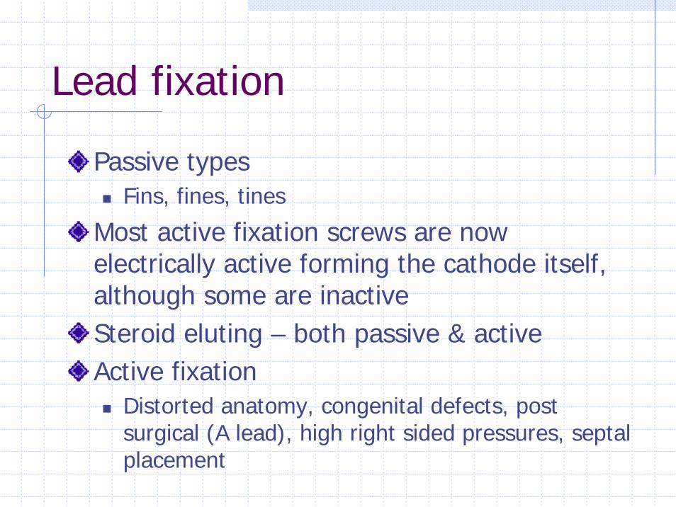
Lead fixation
Passive typesFins, fines, tines
Most active fixation screws are now electrically active forming the cathode itself, although some are inactiveSteroid eluting – both passive & active Active fixation
Distorted anatomy, congenital defects, post surgical (A lead), high right sided pressures, septal placement

Active fixation mechanisms
Retractable – easier passage down vasculature but mechanism has higher rate of failureFixed active screws – difficult to pass down veins, apply torque as the lead passes down vein and through tricuspid valveRemember different types
Screws, hooks, barbs

Lead conductor
Multifilament design – to facilitate high tensile strength and reduce metal fatigueOther types include – unifilar and cable designsBipolar leads – parallel, co-axial (most common), individually coated wires wrapped in a single multifilar arrangement, mixture
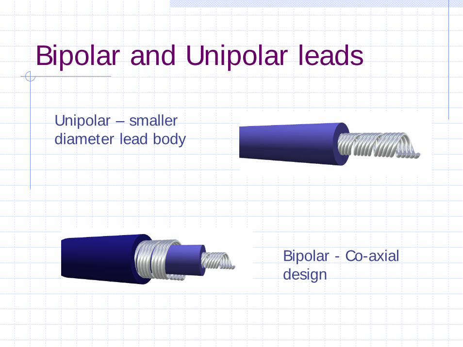
Bipolar and Unipolar leads
Unipolar – smaller diameter lead body
Bipolar - Co-axial design

Conductor materialsAlloy MP35N
Cobalt, nickel, chronium, molybdenum
Elgiloy Susceptible to corrosion as a lead, OK as an electrode material
Nickel-silver – Drawn Brazed Strand (DBS) has 6 nickel alloy wires drawn together with heated silver
breaks down polyurethane due to MIO (Metal Ion Oxidation) process – seen in Medtronic 6972 leads
Lead InsulationPolyurethane Vs Silicone
Polyurethane polymers with widest usePellathane 80A and Pellathane 55d
BUT ** Pellathane 80A had a high failure rate due to small insulation cracks appearing after heating and cooling processes during manufacture. With environmental stresses the cracks deepened – insulation failureIn contact with silver chloride conductors –oxidative stress may occur causing failure of insulation from insidePolyurethane – easier to move

Advantages polyurethane
High tear strengthHigh cut resistanceLow friction in bloodHigh abrasion resistanceLess thrombogenicSuperior compressive properties
Advantages Silicone
FlexibleGood performance record > 30 yrsEasy fabrication & moulding

Disadvantages Polyurethane
Relatively stiffSensitive to manufacturing processesPotential – environmental stress cracking (Pellathane 80A)Potential MIO (Pellathane 80A & 55D)

Disadvantages Silicone
Tears easilyCuts EasilyHigher friction in bloodMore thrombogenic
Some leads have silicone body with poyurethane coating (Fast pass coating)
When implanting 2 leads – same vein – use same material for easier use

Lead connector
Standardized IS13.2 mm diameter In-line bipolar configuration (not bifurcated)
Pulse Generator
Power sourceOutput circuitry (pacing)Input circuitry (sensing) Timing circuitHeader blockRR sensorTelemetry Microprocessor (storage diagnostics)
Power source
PreviouslyNuclear, photoelectric cell, rechargeable nickel-cadmium cell & biogalvanic energy
NowLithium-IodineLithium – anode & provides electronsIodine – cathode & recieves the electronsAnode & cathode separated by electrolyte which serves as a conductor of ionic movement but as a barrier to electron transfer Circuit completed by external load (leads & myocardium)

Battery Voltage
Battery voltage depends on chemical compositionLithium Iodine
BOL = 2.8vERI = 2.4v (90 % has been used)Exponentially decreases until EOL is reachedEOL = 1.8v
Longevity – contributing factors
Chemical composition of batterySize of batteryExternal load
Pulse amplitude, duration, stimulation frequency, total pacing lead impedance, amount current required to operate circuitry & store diagnostics
Amount – internal dischargeVoltage decay characteristics
Longevity
Longevity (years) = Ampere-hours x 114current drain

Finally - calculations
Ohms Law V= I x REnergy E = V2/R x tConstant current stimulation (Rheobase/chronaxie)Slew Rate = Δv/ΔtLongevity = ampere-hrs/current drain x 114TO DO
Other energy equationsNoise sampling equation

And Finally !
E = V2/R x tE = VITE = I2RTNoise sampling Period (NSP) – Convert to Hz (frequency per second) to enable trigger responseHz = 1/t (ms) eg.NSP = 125ms, Hz = 1000/125 = 8Hz