physics book-5 - · pdf fileinduced in arm ea, hd, fb and gc, since these arms are parallel...
TRANSCRIPT

1 SCO 101, Phase-1, Urban Estate, Dugri, Near LIC Building, Ludhiana
Phone No : 0161-2490101/1101 www.edusquare.co.in
SOLUTIONS 1. (a) S.I. unit of magnetic flux is weber. It is a scalar quantity.
(b) The current in the wire produces a magnetic field vertically downward in the vicinity of the coil.
When the current in wire BA decreases, according to Lenz’s law, the current induced in the coil opposes
this decrease; so the current in the coil will be in clockwire direction.
2. The current induced in the coil will oppose the approach of magnet, so this nearer face of the coil will act as
north pole; therefore on viewing from the magnet side the current in the coil will be anticlockwise.
3. (a) Due to the motion of coil, the magnetic flux linked with the coil increases. So by Lenz’s law, the
current induced in the coil will oppose this increase, hence tend to produce a magnetic field upward, so
current induced in the coil will flow anticlockwise. i.e., along PSQP
(b) Loop abc is entering the magnetic field, so magnetic flux linked with it begins to increase. According
to Lez law, the current induced opposes the increases in magnetic flux, so current induced will be
anticlockwise which tends to decrease the magnetic field. Loop defg is leaving the magnetic field; so flux
linked with it tends to decrease, the induced current will be clockwise to produce magnetic field downward
to appose the decrease in magnetic flux.
4. (a) Due to flow of high frequency alternating current in the coil, magnetic flux linked with the metallic
piece changes by a large amount, so heavy eddy currents are induced in the metallic piece. These currents
cause metallic piece to get heated.
(b) (a) When the magnet is rotated about its own axis, then due to symmetry of magnet the manetic flux
linked with circular coil remains unchanged, hence no emf is induced at terminals of coil.
(b) When the magnet is rotated about an axis perpendicular to the length, the positions of N and S poles
of magnet changes continuously; so the magnetic flux linked with the coil changes continuously; hence the
emf is induced at the terminals of the coil.
5. (a) No, the acceleration of magnet will be less than the acceleration due to gravity ‘g’, because the
current induced in the coil will oppose the fall of the magnet.
(b) Yes, when magnet falls e.m.f is induced in the ring, but as the ring has a cut, it has infinite resistane,
so current induced will be zero, hence no opposing force will act on the magnet, so the acceleration of
ring will be equal to g.
6. (a) EMF is induced in an arm which is perpendicular to both v and B and induced emf will be be B v l.
No emf is induced in arms EF, HG, AB, DC since these arms are parallel to magnetic field B . No emf is
induced in arm EA, HD, FB and GC, since these arms are parallel to velocity .v
EMF Bvl is induced in arms EH, FG, AD and BC. Since these arms ares perpendicular to both v and
B .
(b) BA Blx Blvt , max Blb
PHYSICS BOOK-5 HOME ASSIGNMENT SOLUTIONS ELECTROMAGNETIC INDUCTION

2 SCO 101, Phase-1, Urban Estate, Dugri, Near LIC Building, Ludhiana
Phone No : 0161-2490101/1101 www.edusquare.co.in
EMFd
e Blvdt
7. (a) (i) The change in flux linked with both identical coils is the same, so emf induced d
dt
is the
same for both coils.
(ii) Current induced 1
IR R
As resistivity of copper is less than that of aluminium, so current
induced will be more in copper coil.
(b) (i) When the bar maget falls through the coil, the magnetic linked with the coil changes, so an emf (or
pd) is developed across the coil. Initially, the rate of increase of flux increases, becomes maximum and
then it decreases, becomes zero, Now, magnetic flux begins to decrease, the rate of decrease increase
becomes maximum and then it decreases and when the magnet id sufficiently far on the other side, the
flux becomes zero and so pd induced becomes zero.
(ii) Negative Peak is longer than positive Peak because magnet moves out of coil faster tha it moves into
the coil, so the rate of decrease of magnetic flux is faster than the rate of increase of flux.
11. (D) The energy of the field increases with the magnitude of the field. Lenz’s law infers that there is
an opposite field created due to increase or decrease of magnetic flux around a conductor so as to hold
the law of conservation of energy.
12. (D) i Qt tR R
13. (C) As it is seen from the magnet side, induced current will be anticlockwise.
14. (B) qR
qR (area under the curve) R4 0.1
102
= 2 Weber.
15. (B) The magnitude of induced e.m.f. is directly proportional to the rate of change of magnetic flux.
Induced charge doesn’t depend upon time.
16. (D) = 3t2 + 3, so it’s a parabola since it is not in the form y = 4ax2
it does not pass through origin
17. (C) Theory Based
18. (B) Theory Based
19. (B) Theory Based
20. (A) According to Lenz’s law.
21. (B) 10 2
42
Q CR
22. (D) emf Blv 4 30.2 10 1.5 50 1.5 10 V
3 SCO 101, Phase-1, Urban Estate, Dugri, Near LIC Building, Ludhiana
Phone No : 0161-2490101/1101 www.edusquare.co.in
23. (A) Area of square loop, A=10cm10cm
A= 100cm2 = 100 10–4m2 = 10–2m2
Initial magnetic flux linked with loop 1 = B1Acos = 0.1 10–2 cos 45o 2 30.1 10 1 10
2 2
Wb
Final magnetic flux linked with loop 2 = 0Wb 2B 0
The induced emf in the loop is 2 1d
dt t
3
33
100
10210 V
0.7 0.7 2
The induced current in the loop is
310 VI
R 1
= 10–3A = 1.0 mA
24. (D) No flux change is taking place because magnetic field exists everywhere and is constant in time and
space.
25. (D) Conductor cuts the flux only when it moves in the direction of M.
26. (C) 4 3180 10000.2 10 1 10 V
3600e Bvl
27. (D) By Fleming’s right hand rule.
28. (D) 2 1cos cosNBA
et
5 o o800 4 10 0.05 cos90 cos0
0.1
0.016V
29. (C) 221 1
0.1 2 10 0.12 2
e B r 210 V
30. (C) As v and l are parallel.
32. L I LI
The slope of I
of straight line is is equal to self-inductance L. It is larger for inductor A; therefore inductor A
has larger value of self inductance’L’
33. Induced emf i
e Lt
340 10
numerically2
eL
i
t
320 10 20H mH
34. Relative permeability 10
10000.01
mediumr
air
L mH
L mH
35. The back emf induced in the coil oppose the change in current. 36. Due to large restoring couple developed in the coil.
37. (i) when the relative distance between the coil is increased, the leakage of flux increases which reduces the magnetic coupling of the coils. So magnetic flux linked with all the turns decreases. Therefore, mutual
inductance will be decreased.
(ii) Mutual inductance for a pair of coil is given by 1 2M K L L Where 2N A
Ll
and L is called
self inductance. Therefore, when the number of turns in each coil increases, the mutual inductance also
increases.
(iii) When a thin sheet is placed between the two coils, the mutual inductance decreases due to the

4 SCO 101, Phase-1, Urban Estate, Dugri, Near LIC Building, Ludhiana
Phone No : 0161-2490101/1101 www.edusquare.co.in
opposite eddy current set-up in the iron sheet. As rate of change of magnetic flux in the coil decreases,
induced emf also decreases. Therefore, mutual inductance decreases.
38. Self inductance of a solenoid of length L2 ,mn AL where n is number of turns per metre.
2
1 0 1 1L n A L , 2
2 0 2 2L n A L
If 1I is the current in outer solenoid, then magnetic field at axis , 1 0 1 1B n I
Magnetic flux linked with the secondary coil 2 2 1 2 2 0 1 1 2n L B A n L n I A 0 1 2 2 1n n L A I
20 1 2 2
1
M n n L AI
….(1)
Now 2 2
1 2 0 1 1 0 2 2,L L n A L n A L
1 2 0 1 2 1 2L L n n L A A ….(2)
2
11 2
AM
AL L as
2 1 2 1 2,A A A A A 1 2M L L
39. The bulb P will light up earlier, because inductor bulb Q contains extra inductance in series; this inductor
opposes the growth the current, So bulb Q will light up later. After some time both the bulbs will glow with
equal brightness.
42. (a) suppose the loop is formed of a number of small elements parallel to the length of wire. Consider an
element of width dr at a distance r from the wire. The magnetic field at the vicinity of wire, 0 ,2
IB
r
downward perpendicular to the plane of paper.
The magnetic flux linked with this element 2 2.B d A 0 02 cos
2 2
I Ia drBdA a dr
r r
Total magnetic flux linked with the loop 0 02 log
2 2
x a x a
e xx
Ia Iadrr
r
0 log2
e
Ia x a
x
Mutual inductance 02 log 12
e
a aM
I x
(b) Induced emf in the element d Bvdr
Net emf induced in the loop
0
2
x a x a
x x
IBvdr vdr
r
0 0 log2 2
x a x a
e xx
Iv I vdrr
r
0 log2
e
Iv x a
x
Given I = 50 A, v = 10 ms–1
0.2m, 0.1mx a
74 10 50 10 0.2 0.1
log2 0.2
e
410 log 1.5e
4 4
1010 2.3log 1.5 2.3 10 1.76 54.05 10 V
43. Area of loop, 28 2 16A cm cm cm 4 216 10 m
Induced emf, B
BA At t t
Here 10.02B
Tst
Induced emf 416 10 0.02 53.2 10 V
5 SCO 101, Phase-1, Urban Estate, Dugri, Near LIC Building, Ludhiana
Phone No : 0161-2490101/1101 www.edusquare.co.in
Induced current,
553.2 10
2 101.6
I AR
Power dissipated, 2
2 52 10 1.6P I R 106.4 10 W
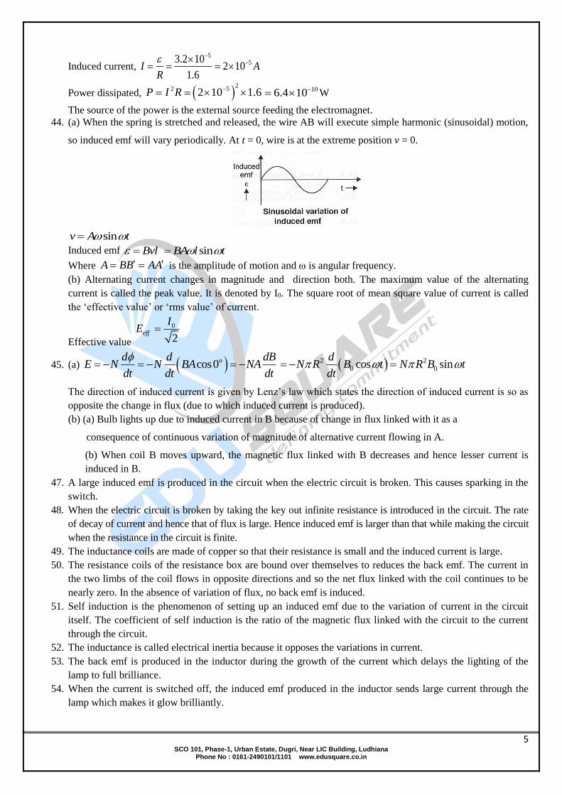
The source of the power is the external source feeding the electromagnet. 44. (a) When the spring is stretched and released, the wire AB will execute simple harmonic (sinusoidal) motion,
so induced emf will vary periodically. At t = 0, wire is at the extreme position v = 0.
sinv A t
Induced emf Bvl sinBA l t
Where A BB AA is the amplitude of motion and is angular frequency.
(b) Alternating current changes in magnitude and direction both. The maximum value of the alternating
current is called the peak value. It is denoted by I0. The square root of mean square value of current is called
the ‘effective value’ or ‘rms value’ of current.
Effective value
0
2eff
IE
45. (a) ocos0d d dB
E N N BA NAdt dt dt
2 2
0 0cos sind
N R B t N R B tdt
The direction of induced current is given by Lenz’s law which states the direction of induced current is so as
opposite the change in flux (due to which induced current is produced).
(b) (a) Bulb lights up due to induced current in B because of change in flux linked with it as a
consequence of continuous variation of magnitude of alternative current flowing in A.
(b) When coil B moves upward, the magnetic flux linked with B decreases and hence lesser current is
induced in B.
47. A large induced emf is produced in the circuit when the electric circuit is broken. This causes sparking in the
switch.
48. When the electric circuit is broken by taking the key out infinite resistance is introduced in the circuit. The rate
of decay of current and hence that of flux is large. Hence induced emf is larger than that while making the circuit
when the resistance in the circuit is finite.
49. The inductance coils are made of copper so that their resistance is small and the induced current is large.
50. The resistance coils of the resistance box are bound over themselves to reduces the back emf. The current in
the two limbs of the coil flows in opposite directions and so the net flux linked with the coil continues to be
nearly zero. In the absence of variation of flux, no back emf is induced.
51. Self induction is the phenomenon of setting up an induced emf due to the variation of current in the circuit
itself. The coefficient of self induction is the ratio of the magnetic flux linked with the circuit to the current
through the circuit.
52. The inductance is called electrical inertia because it opposes the variations in current.
53. The back emf is produced in the inductor during the growth of the current which delays the lighting of the
lamp to full brilliance.
54. When the current is switched off, the induced emf produced in the inductor sends large current through the
lamp which makes it glow brilliantly.

6 SCO 101, Phase-1, Urban Estate, Dugri, Near LIC Building, Ludhiana
Phone No : 0161-2490101/1101 www.edusquare.co.in
55. The eddy currents generated in the tube oppose the downward motion of the magnet and ultimately this
opposing force becomes equal to the gravitational pull and the magnet moves with terminal velocity.
56. Yes. As the resistivity varies with temperature so the magnitude of induced current and hence damping action
of the magnetic field produced by the coil depends upon temperature. 57. (i) When switch S is closed, the bulb will give full brightness slowly, because inductor opposes the rise of
current in the circuit depending on the value of ratio .L
R(L = inductance, R = resistance of bulb).
(ii) When battery is replaced by an ac source, the inductor offers reactance (L), so impendance of circuit
increases and the bulb will glow with less brightness.
58. No. Equal and oppositely directed induced emf’s are set up in the two axles when considered a part of the
loop. Hence no current is setup in the loop. The magnetic flux linked with this loop does not change with time.
59. Yes. The current in B will be in the direction of current in C. When we move the coil A towards the coil B.
The magnetic flux through B due to the field produced by A increases. So the induced current in R should be
opposite to that in A. Hence, it should be in the direction of current in C.
60. (i) The lamp L2 in series with R will light up to full brilliance first. The back emf in inductor will delay
the lighting of L1.
(ii) After the current becomes steady, induced emf in L1 is zero since resistance of inductor is Equal to R,
so both the lamp will light up equally after sometime.
61. When the current is switched off, large induced emf is produced in the electromagnet coil. The lamp or resistor
provides easy path for the current due to the induced emf and avoids. Sparking at the gap of the key.
62. The circuit diagram of the coil is as shown in the figure
2L L L M
For perfect coupling we have
1 2
1M
kL L
2
1 2M L L
Since 1 2 .L L L Hence
2 2M L or M L
Total inductance for perfect coupling is given by 2 0eL L L L
63. (a) (i) Induced current in the coil is anticlockwise when seen from above along a b c d. This can be determined
using the Fleming left hand rule. Here B is from N to S (Direction of first finger) part b c of the coil is going up
(direction of thumb). And so the current will be from b to C (direction of middle finger).
64. No Induced current is produced only when magnetic flux linked with the coil varies. That is not the case here.
65. No. the current is induced only when magnetic flux linked with the coil varies. It is not the case when electric
flux varies.
66. Plate ‘a’ is positive and ‘b’ is negative. The induced current in the coil should be clock wise (b x y a) in
accordance with the Lenz’s law. This produces accumulation of + VE charge on plate a making it positive.
67. (A) Theory Based
68. (A) 3500 4 10
1henry2
NN Li L
i
69. (B) Energy stored = 21LI
2
7 SCO 101, Phase-1, Urban Estate, Dugri, Near LIC Building, Ludhiana
Phone No : 0161-2490101/1101 www.edusquare.co.in
70. (C) Magnetic flux = LI
By analogy, since physical quantities mass (m) and linear velocity (v) are equivalent to electrical
quantities inductance (L) and current (I) respectively. Thus magnetic flux = LI is equivalent to
momentum p m v
71. (A) 2 2
2 1 1 22 1 1
2 2 1
. . 4L N N
L N i e L L LL N N
72. (C) 2
0 A/lL N
73. (C) 2 1
1 2/ /
e eM
di dt di dt
Also, 1 21 1 2 2.
di die L e L
dt dt
2 1 21 2 1 2
1 2
e eM L L M L L
di di
dt dt
74. (C) 40 1 2 2.4 10
N N AM H
l
75. (B)
76. (B)
77. (A) Induced e.m.f. 3100 10di
e Mdt
10
0.1M
310 1M H mH
78. (A) The inductances are in parallel
Leq = 3
13 3
LH
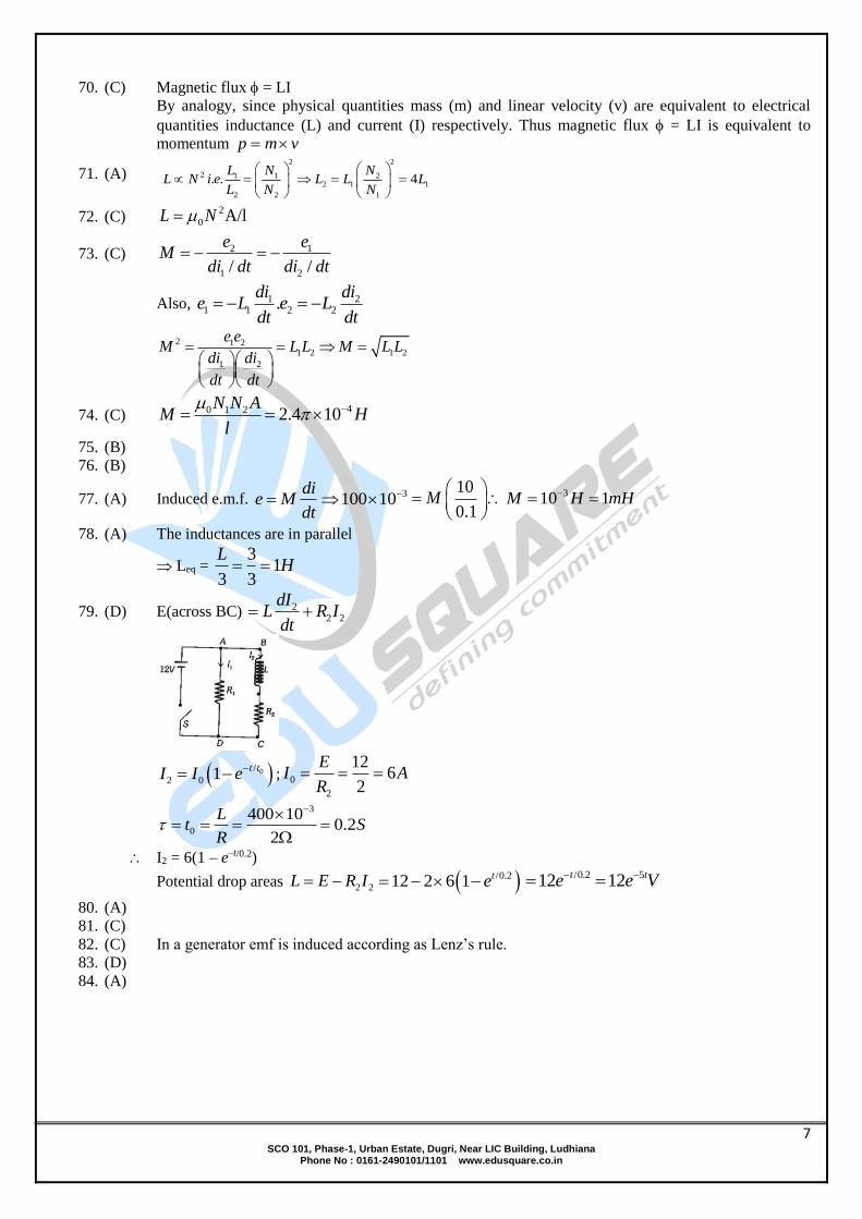
79. (D) E(across BC) 22 2
dIL R I
dt
0/
2 0 1t t
I I e
; 0
2
126
2
EI A
R
3
0
400 100.2
2
Lt S
R
I2 = 6(1 – e–t/0.2)
Potential drop areas 2 2L E R I /0.212 2 6 1 te /0.2 512 12t te e V
80. (A)
81. (C)
82. (C) In a generator emf is induced according as Lenz’s rule.
83. (D)
84. (A)

8 SCO 101, Phase-1, Urban Estate, Dugri, Near LIC Building, Ludhiana
Phone No : 0161-2490101/1101 www.edusquare.co.in
SOLUTIONS 1. (a) Given 0.5sin314I t …(i)
Standard equation of current is 0 sinI I t ..(2)
Comparing (1) and (2), we get 0 0.5 , 314I A
(1) rms value 0 0.50.35
2 2rms
II A A
(2) Frequency 314
50Hz2 2 3.14
f
(b) The phase difference is 180o.
(c) The graph of capacitive reactance XC and frequency f is shown in fig
(d) Given equation is E = 300 sin 314 t comparing with standard equation E = E0 sin t, we have E0 =
300 volt
So 0 300150 2 volt
2 2rms
EE 150 1.414 212V
(e)
/ /
00 0
/ /
00
sin
av
V dt V t dtV
tdt
/
0
0 0
cos
cos cos 0/
tV
V
02V
2. (a) The current leads the applied voltage by rad2
in a purely capacitive circuit; so element ‘X’ is a
pure capacitor. Reactance of capacitor XC = 1
Cwhere is angular frequency of alternating voltage
source.
(b) Alternating current, I = 10 sin 314 t. Comparing its values with standard equation I = I0 sin t,
Peak value I0 = 10 units angular frequency 314rad/s
(i) Effective value 0 5 22
eff
II units
(ii) Frequency of source, 314
50Hz2 2 3.14
f
(c) In given ac, there are identical positive and negative half cycles, so the mean value of current is zero;
but the rms value is not zero.
04
4
T
dt
T
/2 2 22
2 0 0 /22 2
T T T
T
mean
I dt dt dtI
Tdt
PHYSICS BOOK-5 HOME ASSIGNMENT SOLUTIONS
ALTERNATING CURRENT
9 SCO 101, Phase-1, Urban Estate, Dugri, Near LIC Building, Ludhiana
Phone No : 0161-2490101/1101 www.edusquare.co.in
4 2rmsI A
(d) Reactance of inductor XL = 2fL Current in circuit 1
2
NI
fL f Smaller the frequency,
larger is the current; so the current with 220 V, 50 Hz source will be higher.
3. (a) (i) Induced emf, cosd d
BA tdt dt
as B, A, are same for both loops, so induced emf is
same in both loops.
(ii) Current induced, /
AI
R l A l
As area A, length l and emf are same for both loops but resistivity is less for copper, therefore
current I induced is larger in copper loop.
(b) Alternating current changes in magnitude and direction and the mean value of ac over a complete
cycle is zero. Therefore moving coil ammeter will always read zero when connected in an an circuit
of any frequency.
4. (a) (i) The phenomenon involved in mutual induction.
(ii) When a copper sheet is inserted in the gap
between the coils, the eddy currents are induced in the coil, due to which the current in coil B is
decreased and brightness of bulb decreases. (or) Cu allows less magnetic flux to pass through
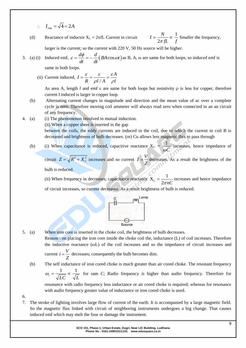
(b) (i) When capacitance is reduced, capacitive reactance XC = 1
C increases, hence impedance of
circuit 2 2
CZ R X increases and so current V
IZ
decreases. As a result the brightness of the
bulb is reduced.
(ii) When frequency in decreases; capacitance reactance C
1X
2 nC increases and hence impedance
of circuit increases, so current decreases. As a result brightness of bulb is reduced.
5. (a) When iron core is inserted in the choke coil, the brightness of bulb decreases.
Reason : on placing the iron core inside the choke coil the, inductance (L) of coil increases. Therefore
the inductive reactance (L) of the coil increases and so the impedance of circuit increases and
current V
iZ
decreases; consequently the bulb becomes dim.
(b) The self inductance of iron cored choke is much greater than air cored choke. The resonant frequency
1 1r
LC L for sam C; Radio frequency is higher than audio frequency. Therefore for
resonance with radio frequency less inductance or air cored choke is required; whereas for resonance
with audio frequency greater value of inductance or iron cored choke is used.
6.
7. The stroke of lighting involves large flow of current of the earth. It is accompanied by a large magnetic field.
So the magnetic flux linked with circuit of neighboring instruments undergoes a big change. That causes
induced emf which may melt the fuse or damage the instrument.
10 SCO 101, Phase-1, Urban Estate, Dugri, Near LIC Building, Ludhiana
Phone No : 0161-2490101/1101 www.edusquare.co.in
8. (A) Emf = e = e0sin; e will be maximum when is 90o i.e. plane of the coil will be horizontal.
9. (B) This is the case of periodic EMI
10. (D) cos sinNBA t NBA t
11. (B) With the increasing speed, increases. Thus current reduces due to increase in the back emf.
Moreover V K
iR
. More will lead to the lesser current.
12. (B) The emf induced is directly proportional to rate at which flux is intercepted which varies directly
as the speed of rotation of the generator
13. (D)
14. (B) In dc ammeter, a coil is free to rotate in the magnetic field of a fixed magnet.
In an alternating current is passed through such a coil, the torque will reverse it’s direction each time
the current changes direction and the average value of the torque will be zero.
15. (C) 20sin 100 0.05I t
2010 2
2rmsI
100 50Hzf
16. (A) The instantaneous value of voltage is 100sin 100 VE t
Compare it with 0 sin VE E t
We get 1
0 100V, 100 radsE
The rms value of voltage is0 100
V 70.7 V2 2
rms
EE
The instantaneous value of current is 0 sin 100 mA3
I I t
Compare it with 0 sinI I t
We get 1
0100 mA, 100 radsI
The rms value of current is 0 100
mA 70.7 mA2 2
rms
II
17. (B) Given equation, e = 80 sin 100t
Standard equation of instantaneous voltage is given by e = em sin t
Compare (i) and (ii), we get em = 80V where em is the voltage amplitude
Current amplitude mm
eI
Z where Z = impedance = 80/20 = 4A
Effective current or root means square current.
4 4 22 2 2.828A
2rmsI
18. (B) 0 0
2cos cos
tE E t E
T
2 50 110cos 10cos 5 3
600 6
volt.
19. (B) For purely capacitive circuit e = e0 sint
0 sin2
i i t
, i.e., current is ahead of emf by 2
11 SCO 101, Phase-1, Urban Estate, Dugri, Near LIC Building, Ludhiana
Phone No : 0161-2490101/1101 www.edusquare.co.in
20. (A) 6
1 1 1
2 1000 2 5 10CX
vC v
00v MHz
21. (C) The circuit element connected to the AC source will be pure resistor. In pure resistive AC circuit,
voltage and current are in the same phase.
22. (A) Compare 220 2 sin100e t V with e = e0 sin t
We get, 0 220 2e V, = 100 rad/s
0 220 2V 220V
2 2rms
ee
The capacitive reactance is 4
6
1 110
100 1 1 10CX
C
23. (A) Phase difference relative to the current 6
)314()6
314(
tt
24. (C) Heat produced by ac = 3 Heat produced by dc
RtiRtirms22 3 22 23rmsl
Airms 46.332
25. (C)
I, instantaneous value of current is
I = I0 sin t
and rms value of current is
Irms = I0 / 2
Here, I instantaneous value of current is
I = 1/ 2 sin t
Thus I0 = 1/ 2
Irms = I0 / 2 1/ 2
2 =
1
2
26. (B)
The household line voltage is of rms value of 220 V. Since peak voltage
Vm = 2 Vrms
= 2 (220 V)
= 414 (220) = 311 V
27. (B) Since Irms = I0 / 2
I = I0 sin t = instantaneous value of current
I0 is the peak value
Imean = 2I0/ = Im.
Im / Irms 0
0
2I 2
I
2 2
28. (B) tttV 200sin50100cos100sin250
VoltsV 500 and Hz100
29. (B) 1. rms value =2
0x
2. 22
x value2sin
2cossin 00
0 rmstx
ttx
3. 2
0
2
000
22 valuecossin
xxrmstxtx 0
20 xx

12 SCO 101, Phase-1, Urban Estate, Dugri, Near LIC Building, Ludhiana
Phone No : 0161-2490101/1101 www.edusquare.co.in
30. Given L C RV 30V,V 30V,V 60V
Phase difference () in series LCR circuit is given by
30 30tan 0
60
C L C L
R
X X X V
R V
0 (zero)
31. Impendance of series LR circuit 2 2
1 LZ R X
When capacitor is also connected in circuit,
Then impedance 22
L L CZ R X X
Clearly impedance of circuit decreases (Z2 < Z1), so the value of current 1V
IZ Z
in the circuit
increases.
32. (i) When ;C LX X the phasor diagram is shown in fig. (a).
(ii) When ,L CX X the phasor diagram in shown in fig. (b).
33. (i) Impedance of circuit
2
2 1Z R L
C
(ii) Resonant frequency 1
2rf
LC
34. For same current value, the total impedence
2
2 1R L
C
Must remain same.
Thesefore, 1
LC
must remain same. As frequency () is doubled, L and C must both be halved
simultaneously.
35. Impedance
2
2
0
0
1Z R L
C
At resonance 0 0
0
1 1L
C LC
min max, IV
Z RR
(i) For same value of inductance L and resonant frequency
0
1;
LC the capacitance values are

13 SCO 101, Phase-1, Urban Estate, Dugri, Near LIC Building, Ludhiana
Phone No : 0161-2490101/1101 www.edusquare.co.in
same.
(ii) As max
VI
R current is maximum for X, minimum for Z, so resistance is minimum for X and
maximum for Z i.e., .X Y ZR R R Quality factor L
QR
is minimum for X.
Impedance at frequency 0 is minimum and is equal to resistance R for the case under consideration. This,
impendance at the resonant frequency 0 is purely resistive in nature.
36. (i) When circuit element is X, the current is in phase with the applied emf, this implies that X is pure
resistance.
When circuit element Y is connected, the current leads the voltage by ,2
so Y is pure capacitance.
(ii) Resistance of X = R, C
IR
or 2V
R ..(1)
Reactance of Y, XC = 1
C
2C C
V VI C
X X ….(2)
This implies CX R
When R and C are connected in series acorss same voltage source, then
Impedance 2 2 2 2 2CZ R X R R R ..(3)
Current in circuit 2
V VI
Z R
From (1), 1
2 2 12
VI A
R
(iii) Net impendance
2
2 1Z R
C
i.e., impedance decreases with increase of angular frequency .
When = 0, Z =
When = , Z = R.
The graph of impedance Z versus is shown in fig
37.
38.
39.
40.
41.
14 SCO 101, Phase-1, Urban Estate, Dugri, Near LIC Building, Ludhiana
Phone No : 0161-2490101/1101 www.edusquare.co.in
42. (A)
43. (B) The applied voltage is given by 2 2
R LV V V
2 2
200 150 250V volt
44. (A) Figure given in the question shows that current I leads the emf E by a phase angle 4
. Therefore,
the circuit can be R–C circuit alone.
1tan CX
R CR
1CX
C
1tan
4 CR
11
CR
Compare E = E0 sin (100t) with E = E0 sin t, we get = 100 rad s–1
1 1
100CR
When R = 1k = 103
5
5
110 10
10C F F
45. (D) 22 2 2 2Z R X R fL
22 0.4
30 2 50 900 1600 50
2004
50
Vi
Z ampere
46. (B) In RC series circuit voltage across the capacitor leads the voltage across the resistance by 2
47. (B) The current in the circuit rmsrms
VI
Z
0 300 2300V
2 2rms
VV
2 22 230 10 10 30L CZ R X X
30010A
30rmsI
48. (A)
49. (A) 2280 100 40 100VE
50. (B) In an LCR circuit in series, as 1
LC
, impedance is purely resistive. The phase between the
current and voltage is zero. Therefore power factor cos cos0 1
. Therefore statement (b) is
wrong.
51. (D) Given 21 1
LC LC
or 4
3 6 8
1 110
10 10 10 10
15 SCO 101, Phase-1, Urban Estate, Dugri, Near LIC Building, Ludhiana
Phone No : 0161-2490101/1101 www.edusquare.co.in
4 310 10 10LX L
52. (A) tan L CX X
R
otan 303
CC
X RX
R
otan 303
LL
X RX
R
XL = XC Condition for resonance
So, = 0o
ocos0P VI
22 220
242W200
VP
R
53. (A) If the capacitance is removed, it is an L-R circuit = 60o otan tan 60 3LX
R
If inductance is removed, it is a capacitive circuit or R-C circuit. || is the same
1L
C
This is a resonance circuit.
; ; 200Vrmsrms rms
EZ R I E
R
200V2A
100rmsI
54. (C) In non resonant circuits
2
2 1Z R L
C
> r, effect of inductive is more.
55. (A) At resonance LCR series circuit behaves as pure resistive circuit. For resistive circuit = 0o.
56. (D) 22
R L CV V V V
RV V L CV V
Reading of voltmeter = 220V
Reading of ammeter 220
2.2A100
rmsrms
EI
Z
57. (C)
2
2 12
2Z R fL
fC
From above equation at f = 0, z =
When 1
2f
LC (resonant frequency) Z = R
For 1
2f Z
LC starts increasing.
i.e. for frequency 0 – fr, Z decreases and for fr, to , Z increases.
This is justified by graph c.
58. (A)
59. (A) Q factor is given by 1 L
R C
16 SCO 101, Phase-1, Urban Estate, Dugri, Near LIC Building, Ludhiana
Phone No : 0161-2490101/1101 www.edusquare.co.in
So, for large quality factor the inductance should be large and resistance and capacitance must be
small.
60. (a) Power dissipated 0 0
1cos
2P V I
Here 0 0230 , 10 ,2
V V I A
1
230 10cos 0.2 2
P
(b) Phase difference between V and D is zero.
0 010 , 50 ,I A V V
Power 0 0
1cos cos
2rms rmsP V I V I o1
50 10cos0 250W2
(c) The power factor (cos ) is the ratio of resistance and impedance of an ac circuit i.e.,
Power factor, cosR
Z
Maximum Power factor is 1 when Z = R i.e.,
when circuit is purely resistive. Minimum power factor is 0 when R = 0 i.e., when circuit is purely
inductive or capacitive
(d) The power cosrms rmsP V i
where cos ;R
Z for ideal inductor R = 0,
cos 0R
Z
cos 0rms rmsP V i i.e. power dissipated by an ideal inductor in ac circuit is zero.
61. (a) Power dissipated in a.c. circuit, cosrms rmsP V I where cos .R
Z
For an ideal capacitor 0 cos 0R
RZ
cos 0 0rms rms rms rmsP V I V I (zero).
i.e., power dissipated in an ideal capacitor is zero.
(b) Power in ac circuit, cosrms rmsP V i
As rms values of current and voltage are also called effective values i.e.
coseff effP V i ….(1)
But cos power factor R
Z
In a purely resistive circuit ,cos 1Z R and eff eff
ff
V Vi
Z R
Substituting these values in (1), we get
2
. 1eff eff
eff
V VP V
R R .
(c) Power factor cos ,R
Z when
2 2Z R X
(i) 2 2, 1CX X aR Z R aR R a
17 SCO 101, Phase-1, Urban Estate, Dugri, Near LIC Building, Ludhiana
Phone No : 0161-2490101/1101 www.edusquare.co.in
2 2
1cos
1 1
R
R a a
(ii) LX X bR
22 21Z R bR R b
2 2
1cos
1 1
R
R b b
(d) Advantage : Line loss is low.
Disavantage : high voltage is dangerous.
62.
63.
64.
65. (a) emf induced sinNBA t
Given N = 20, 28cm 8 10 m,r 1 350rads ,B 30T 30 10 T,R 10
(i) Maximum value of induced emf 2
0 NBA NB r
2
3 220 30 10 3.14 8 10 50volt 0.603volt
(ii) Average value of induced emf, sin 0av avNBA t
Since average value of sin t over a complete cycle is zero,
R.M.S value of emf, 0
2rms
0.603 0.603 20.426V
22
Power dissipated on heat
2
2 rmsI R
R
2
20.426
1.8 1010
watt = 18 mW
(b) Given 20.09 ,R 15.0A m ,
150
20, 15.0 , 0.5 , Hz2
N R B T f
1300rads
(i) Maximum emf, max NBA 20 0.5 0.09 300volt 270V
(ii) Average emf for complete rotation = 0
Since average value of sin t is zero.
(c) 630 ,C 0.25 0.25 10 F,VR F
5100 ,ω 1.00,000 10 rad/sV
Reactane 5 6
1 140
10 0.25 10CX
C
Impedance of circuit 2 22 2 30 40 50cZ R X
Current in circuit 100
250
VI A
Z
Voltage across resistance 30 2 60VRV RI
Voltage across capacitance, 40 2 80Vc cV X I

18 SCO 101, Phase-1, Urban Estate, Dugri, Near LIC Building, Ludhiana
Phone No : 0161-2490101/1101 www.edusquare.co.in
The sum of voltages is more than the applied voltage; this is due to the phase difference of 2
between voltages RV and CV .
66. (a) Given 6200 , 15.0 15.0 10 ,R C F F V 220, 50f Hz
Capacitance reactance 1 1
2CX
C fC
6
1212
2 3.14 50 15.0 10
Impedance of circuit, 2 2
CZ R X 2 2
200 212 291.5
RMS current, 220
0.75291.5
rmsrms
VI A A
Z
Voltage across resistance, 200 0.75 150VRV RI
Voltage across capacitor, 212 0.75 159VC CV X I
Algebraic sum of VR and VC +VC= 150 +159 = 309 V > 212 V
This is because these voltage are not is same phase but VC legs behid VR by angle /2
2 22 2 150 159 220VR CV V V
(b) Voltage applied 2 2
L RV V V 2 2
200 150 250V
Impedance of circuit, V
ZI
250
505
Phase angle between voltage and current 200 4
tan150 3
L L
R
X V
R V
1 o4
tan 533
(c) (i) When d.c. source is connected across the coil, the hindrance in current is due to pure
resistance of coil, because inductace does not offer any hindrance to steady d.c. current. But when ac
source is conncted across the coil, the hindrance is offered due to both resistance (R) and inductance
(L) of the coil, hence current is reduced.
(ii) Resistance of coil 100 200
1.5 3
dc
dc
Vr
I
Impedance of coil, 100
1001.0
ac
ac
VZ
i
Impedance of RL circuit 2 2
LZ R X or 2 2 2Z R R
2
22 2 200100
3LX Z R
4 9 4100 1 100
9 9
100 5 100 2.234.3
3 3
67. (a) Given 3L 200mH 200 10 H,C 500μF
6500 10 F, 10 , 100rmsR V V

19 SCO 101, Phase-1, Urban Estate, Dugri, Near LIC Building, Ludhiana
Phone No : 0161-2490101/1101 www.edusquare.co.in
(i) Angular (resonant) frequency r at which power factor of the circuit is unity, is given by
1r
r
LC
3 6
1 1
200 10 500 10r
LC
1100rads
Linear Resonant frequency 100 100
15.92 2 3.14 6.28
rrf Hz Hz
(ii) at resonant frequency rf impedance,
Current amplitude , 00
2V VI
Z R
100 210 2 14.1
10A A
(iii) Q-factor
3100 200 102
10
r L
R
(b) For power factor unity, 1
L CX X LC
22 2 2
1 1 1
42L
C f Cf C
Given 6 450 , 100 100 10 10f Hz C F F F
2 2 4
1H 0.10H
4 3.14 50 10L
Current amplitude, 00I
V
Z
At resonance, Z R
00
200 220 2 A
10
VI
R 20 1.414A 28.3A
68. (a) Given Erms = 200 V, L = 5 H, C = 80 F = 80 10–6 F, R = 40
(i) for the maximum current is circuit, XL = XC
1
LC
Resonant frequency 6
1 150rad/s
5 80 10r
LC
2005
40
rmsrms
EI A
Z
Current amplitude 0 2rmsI I 5 1.414 7.07A
(ii) Power dissipated in circuit ocos 0 200 5 1 1000 Wrms rmsP E I
(b) Given, 12V V
50Hz , 0.5I A
/ 3 , ?R
2 2
L
VI
R X
,
2 20.5 12LR X
Now, otan tan 60L LX X
R R
. 3 LR X
Z R
20 SCO 101, Phase-1, Urban Estate, Dugri, Near LIC Building, Ludhiana
Phone No : 0161-2490101/1101 www.edusquare.co.in
Put in (i) 2 20.5 3 12 0.5 2 12R R R 12R
69. Current is secondary coil, 22
0.1220
SS
VI A A
Z
For an ideal transformer
Current in primary coil, S S p pV I V I 22 0.1
0.01A220
S Sp
p
V II
V
70. (a) Transformation ratio S
P
Number of turns in secondary coil (N )
Number of turns in primary coil (N )r
Given NP = 100, r = 100
Number of turns in secondary coil, 100 100 10,000SN rNp
(b) Input voltage VP = 220 V, input power Pin = 1100W
Current in primary coil 1100
5220
inP
P
PI A
V
(c) Voltage across secondary coil (VS) is given by S
P
Vr
V
100 220 22,000V 22kVS PV rV
(d) Current in secondary coil (IS) is given by P
S
Ir
I
50.05A.
100
PS
II
r
(e) Power in secondary coil, Pout = VS IS = 22 103 0.05 = 1100 W
Obviously power in secondary coil is same as power in primary. This means that the transformer is ideal.
71. Given NP = 200, NS = 1000, 4
input pP 10kW 10 W,V 220V
(i) In an ideal transformer 4
output inputP P 10 W
From relation S S
P P
V N
V N out voltage S
S p
p
NV V
N
1000200 1000V
200
Also inputP p pV I
current is primary,
41050A
200
input
p
p
PI
V
72. (C) 1
2 2 50 100LX vL
73. (C)
74. (A) Key Idea: The potential difference across the
series combination of L and C is the difference in potential differences across individuals.
Current through the circuit,
22
rms
L C
Vi
R X X
Given, R = 3, XL = 15
XC = 11, Vrms = 10V
2 2
10
3 15 11i

21 SCO 101, Phase-1, Urban Estate, Dugri, Near LIC Building, Ludhiana
Phone No : 0161-2490101/1101 www.edusquare.co.in
10 102A
59 16i i
Since, L, C and R connected in series combination, then potential difference across R is
VR = iR = 2 3 = 6V
Across L, VL = iXL = 2 15 = 30 V
Across C, iXC = 2 11 = 22 V
So, potential difference across series combination of L and C = VL – VC = 30 – 22 = 8V
Note: In LCR circuit whenever voltage across various elements is asked, find rms values unless state
in the question for the peak or instantaneous value.
75. (B)
76. (A) 5cos 5sin2
V t t
and 2sini t
Power = . . . . cos 0r m s r m sV i
[Since 2
, therefore cos cos 0
2
]
77. (C)
3
.m.s . .
100 100 10cos cos
32 2r r m sP V i
4 310 10 1 102.5
2 2 4
watt
78. (A)
2 2
2 2
2
cos1
rms rms
E R E RP E i
ZR L
C
79. (D) cos , cosP Vi P
80. (D)
2
rmsav
V RP
Z
81. (D) Brightness Pconsumed 1
R. For bulb, Rac = Rdc,
so brightness will be equal in both the cases.
82. (A) Here e = E0 sint, i = I0 sin(t – ) Average power/cycle = EvIv cos
83. (B)
84. (B)
85. (A) cosR
Z , In choke coil
o90 so cos 0
86. (D) Efficiency of a transformer,Power output
Power input
For an ideal transformer, = 1
Power output = Power input = 60W
87. (A) Given the power output is 50% of the input power, is 1
2s s p pi V i V
; Also given ip = 5A, Vp =
220V and Vs = 2200V
1 1 5A 220V0.25A
2 2 2200V
p p
s s
s
i Vi i
V
88. (C)
89. (A) 200
240V100 120
s s ss
p p
N V VV
N V
Also 240 10
4A120
pss
p s s
iVi
V i i
22 SCO 101, Phase-1, Urban Estate, Dugri, Near LIC Building, Ludhiana
Phone No : 0161-2490101/1101 www.edusquare.co.in
SOLUTIONS 1. (a) -rays.
(b) (i) 10–1 m = 10 cm belongs to short radiowaves.
(ii) 10–12 m =0.01 Ǻ cm belongs to gamma rays.
(c) Microwave.
Application : Used in RADAR system for Aircraft navigation.
(d) (i) wavelength 1 mm belongs to the microwaevs.
(ii) wavelength 10–11 m = 0.1 Ǻ belongs to gamma rays.
(e) The frequency range of visible range of electromagnetic spectrum is 114 10 kHz to 7.5 1011 kHz.
(f) Microwave are used in operating a RADAR.
(g) Microwaves are electromagnetic waves of the order of a few millimetres. They are used in RADAR
because they can be transmitted as a beam in a given direction without any bending.
(h) Ultraviolet light is absorbed by ozone layer.
2. (a) X-rays
(b) Infrared rays are used for viewing objects through haze and fog.
(c) Infrared radiation.
(d) -ray.
(e) X-ray.
(f) All electromagnetic waves travel in vaccum with the same speed :
Ratio = infrared
ultra violet
C1
C
3. (a) γ
radiowaves
C -rays1
C
(b) Wavelength 102 m belongs to radio-waves. This is used to broadcast radio proprammes to long distances.
(c) X-rays.
(d) (i) Infrared waves (wavelength range 1 mm to 700 nm).
(ii) Gamma rays (wavelength range < 10–3 nm)
(e) Name : Microwaves.
Use : For cooking in microwaves ovens.
(f) Frequency of oscillation of magnetic field vector is same as that of electric field vector i.e.,
145 10 Hzv
It lies in visible region.
4. (a) (i) frequency.
(ii) Speed in vacuum remains constant.
(b) (i) The waves of maximum frequency are gamma rays.
(ii) The waves of minimum frequency are ratio waves.
(c) The frequency of the microwaves should match the resonant frequency of the water molecules in the food
item.
(d) In ascending power of frequencies : radiowaves, microwaves, ultraviolet rays, X-rays and gamma rays.
(e) Microwaves are short wavelength waves, so they go straight in a specified direction without any bending.
(f) Electromagnetic waves can travel in vacuum while sound wave cannot travel in vaccum; hence sound
waves are not electromagnetic.
PHYSICS BOOK-5 HOME ASSIGNMENT SOLUTIONS
EM WAVES

23 SCO 101, Phase-1, Urban Estate, Dugri, Near LIC Building, Ludhiana
Phone No : 0161-2490101/1101 www.edusquare.co.in
5. (a) Relation between electric field amplitude E0 and magnetic field amplitude B0 : 0
0
Ec
B (speed of light)
(b) X-rays and radiowaves are electromagnetic waves.
(c) Ultraviolet rays have more frequencies than infrared rays hence ratio ultraviolet
infrared
1v
v
(d) X-rays has shortest wavelength.
6. (a) Wavelength,
8
9
3 10 3 300m cm 7.5cm.
4 10 40 40
c
v
This wavelength corresponds to microwave region (or short radiowaves)
These are used in (i) Radar (ii) Microwave ovens.
(b) (i) E
B speed of light 83 10 m/sc
(ii) K, E, B from a right handed system. As wave propagration vector K is along y-axis; electric field E
must be along Z-axis and magnetic field B along X-axis.
(c) (i) Microwaves (ii) Radiowaves
(iii) Gamma rays (iv) X-rays.
7. (a) Source of electromagnetic Waves : The source of electromagnetic waves in an accelerated (or
decelerated) charge or an oscillating LC circuit. In an electromagnetic wave, the electric field vector E and
magnetic field vector B are mutually pendicular and also perpendicular to direction of wave propagation such
that wave propagation vector ,K electric field vector E and magnetic field vector ,B from a right handed
orthogonal system.
The speed of waves in vacuum is the same for different parts of electromagnetic spectrum.
(b) (i) Microwaves are used in RADAR; because they go straight and are not absorbed by the atmosphere.
(ii) X-rays are used to photograph the internal parts of human body; because they can penetrate light
elements (flesh).
(iii) Infrared radiations are used for taking photographs of sky during light and foggy conditions because
they penetrate fog and are not absorbed by the atmosphere.
(c) (i) Infrared radiation produce intense heating effect.
One more Apllication : Infrared radiations are used for taking photographs during the conditions of fog
and smoke etc.
(ii) Ultraviolet radiations are absorbed by the ozone layer in the atmosphere.
One more Application : Ultraviolet radiations are used to destroy bacteria and for sterilizing surgical
instruments.
(iii) X-rays are used to study crystal structure.
One more Application : X-rays are used to diagnose diseases and defects e.g., crack in bones, detection of
tumours, stone in kidney and gall bladder etc.
8. (a) (i) Microwaves : Frequency range 3 1011 Hz 81 10 Hz. These are suitable for the radar system,
used in aircraft navigation.
(ii) Ultraviolet rays : Frequency range 161 10 Hz
148 10 Hz. They are used to detect invisible
writing, forged documents and finger prints.
(iii) Gamma rays : Frequency range 5 1020 Hz 193 10 Hz. Use For the treatment of cancer cells.
(b) (a) Short radiowaves 10m 30MHzv are used in statellite communication.
(b) X-rays are used for studying crystal structure.
(c) -radiation is similar to the radiation emitted during the decary of radioactive nuclei.
(d) Visible radiation has a wavelength range of 390 nm – 700 nm.

24 SCO 101, Phase-1, Urban Estate, Dugri, Near LIC Building, Ludhiana
Phone No : 0161-2490101/1101 www.edusquare.co.in
(e) Ultraviolet light is absorbed from sunlight by ozone layer.
(f) Infrared radiation produces intense heating effect.
(c) Characteristics of electromagnetic waves:
Use of radiowaves :
(i) Radiowaves are used for broadcasting radio and T.V. programmes to different places.
(ii) Radiowaves are used in cellular phones to transmit voice communication in the ultra high frequency
(UHF) band.
Uses of Microwaves :
(i) microwaves are used Radar system installed for aircraft navigation.
(ii) Microwaves are used in microwave ovens for cooking and keeping the food fresh.
In such ovens the frequency of microwaves is selected to match the resonant frequency of water
molecules so that the energy from these waves is transferred efficiently as kinetic energy of water
molecules which is shared by the entire food without any waste of energy.
9. (a) Infrared radiations get readily absorbed by water molecules in most materials. This increases their
thermal motion and heats them up.
(i) on shorter wavelength side are visible radiations.
(ii) on longer wavelength side are microwaves (or short radiowaves).
(b) (i) 1 corresponds to ultraviolet spectrum.
(ii) 2 corresponds to radio waves.
(iii) 3 corresponds to infrared rays order : 2 3 1.
10. (a) Given equation is 11 130sin 2 10 300 VmyE t x
Comparing with standard equation 1
0 sin Vm ,yE E t kx we get
1 11 1
0
230Vm , 2 10 rads ,E k
1300 m
Wavelength, 2 1
m m300 150
36.67 10 m
(b) The wave is propagating along X-axis, electric field is oscillating along Y-axis, so according to right
hand system of , ,E B K the magnetic field must oscillate along Z-axis.
70
0 8
3010 T.
3 10
EB
C
Equation of oscillating magnetic field is 0 sinZB B t kx T
7 1110 sin 2 10 300zB t x T
11. (i) Standard equation of magnetic field is 0 sinyB B t kx T
Comparing this equation with the given equation, we get
6 11 1
0
28 10 , 2 10 rads ,k 300B T
Wavelength, 2 1
m300 150
(ii) 6 8 3 1
0 0 8 10 3 10 2.4 10 VmE B c .
According to right hand system of , , ,E B K the electric field oscillates along negative Z-axis, so equation is
3 11 12.4 10 sin 2 10 300 VmZE t x
12. Charge on each plate of a parallel plate capacitor
q t t A q

25 SCO 101, Phase-1, Urban Estate, Dugri, Near LIC Building, Ludhiana
Phone No : 0161-2490101/1101 www.edusquare.co.in
But 0t E t
0q t AE t
Where t instantaneous charge per unit area E t electric field strength
But E t A electric flux E t
0 Eq t t
Rate of change of charge
0
Edq t d t
dt dt
Rate of change of charge 0 rate of change of electron flux E
The quantity
0
Ed t
dt
is named as displacement current.
13. (B) Factual
14. (C) Factual
15. (D) Factual
16. (C) 8
2
10
3 101.5 10 m
2.0 10
c
v
17. (D) 2
0 0
1
2I E c or 0
0
2IE
c
0 12 8
2 4
8.85 10 3 10E
= 55.5 NC–1
18. (C) Factual
19. (B)
2
0 0
EB ES
C
42
8 7
1026.5Wm
3 10 4 10
20. (C) dq
Idt
21. (A) We know that, E0 = cB0
2c v
k
2k
Thus, 0 0E B
k
or 0 0E k B
22. (A) Average energy density of electromagnetic wave,
22 12
. 0 0
1 18.85 10 50
2 2avu E 8 310 J/m
23. (B) Comparing the given equation with the equation of plane electromagnetic wave,
0 coszE E t kx
We have 86 10 and k = 4 Velocity of light in medium
886 10 3
104 2
vk
m/s
Refractive Index,
8
8
3 102
310
2
c
v
26 SCO 101, Phase-1, Urban Estate, Dugri, Near LIC Building, Ludhiana
Phone No : 0161-2490101/1101 www.edusquare.co.in
24. (C) . BdE dl
dt
or 22
dE r kt r
dt
2
krE
25. (C) 12
0
3
8.85 10 10 1
10
KAC
d
88.85 10 F
88.85 10 25d dV
I CV Cdt dt
62.2 10 A 2.2 A
26. (A) E = VB, Fmax = qEo

27 SCO 101, Phase-1, Urban Estate, Dugri, Near LIC Building, Ludhiana
Phone No : 0161-2490101/1101 www.edusquare.co.in
SOLUTIONS
1. (B) Emf induces across the length of the wire which cuts the magnetic field. (Length of c = Length
d) > (Length of a = b). So )( dc ee > )( ba ee
2. (A) Speed of the magnet
smv /21
21
Speed of the coil
smv /25.0
12
Relative speed between coil and magnet is zero, so there is no induced emf in the coil.
3. (D) Magnetic lines are tangential to the coil as shown in figure. Thus net magnetic flux passing
through the coil is always zero or the induced current will be zero.
4. (A) We know that in this case acceleration of falling magnet will be lesser than g. If ‘g’ would have
been acceleration, then distance covered mgt 52
1 2 .
Now the distance covered will be less than 5 m. hence only option (A) is correct.
5. (D) Rod is moving towards east, so induced emf across it’s end will be e = BVvl vlBH )tan(
Ve 524 1025.0)1010(3
4103 = V10
6. (C) The induced emf between centre and rim of the rotating disc is
voltRBE 322 1010)1.0(1021.02
1
2
1
7. (A) rNL 2 ; 2
1
2
2
1
2
1
r
r
N
N
L
L
2
1
2/2
12
2
r
r
L
L; L2 = 2L
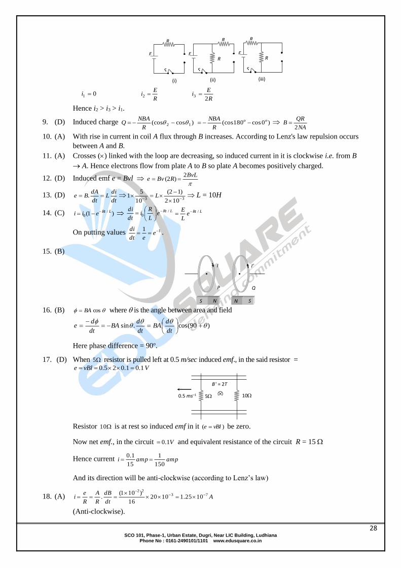
8. (B) At t = 0 current through L is zero so it acts as open circuit. The given figures can be redrawn as
follow.
PHYSICS BOOK-5 OBJECTIVE QUESTIONS
SOLUTIONS ELECTROMAGNETIC INDUCTION
28 SCO 101, Phase-1, Urban Estate, Dugri, Near LIC Building, Ludhiana
Phone No : 0161-2490101/1101 www.edusquare.co.in
01 i R
Ei 2
R
Ei
23
Hence i2 > i3 > i1.
9. (D) Induced charge )cos(cos 12 R
NBAQ )0cos180(cos oo
R
NBA
NA
QRB
2
10. (A) With rise in current in coil A flux through B increases. According to Lenz's law repulsion occurs
between A and B.
11. (A) Crosses () linked with the loop are decreasing, so induced current in it is clockwise i.e. from B
A. Hence electrons flow from plate A to B so plate A becomes positively charged.
12. (D) Induced emf e = Bvl
BvLRBve
2)2(
13. (D) dt
diL
dt
dABe .
33 102
)12(
10
51
L L = 10H
14. (C) )1( /0
LRteii LRteL
Ri
dt
di /0
LRte
L
E /
On putting values 11 eedt
di.
15. (B)
16. (B) cosBA where is the angle between area and field
)90cos(.sin
dt
dBA
dt
dBA
dt
de
Here phase difference = 90o.
17. (D) When 5 resistor is pulled left at 0.5 m/sec induced emf., in the said resistor = VvBle 1.01.025.0
Resistor 10 is at rest so induced emf in it )( vBle be zero.
Now net emf., in the circuit V1.0 and equivalent resistance of the circuit R = 15
Hence current ampampi150
1
15
1.0
And its direction will be anti-clockwise (according to Lenz’s law)
18. (A) Adt
dB
R
A
R
ei 73
22
1025.1102016
)101(.
(Anti-clockwise).
5 10
B ' = 2T
0.5 ms–1
I I'
S N N S
P Q
(i)
S
R
E
(ii)
E
R
S
R
(iii)
E
R
S
R

29 SCO 101, Phase-1, Urban Estate, Dugri, Near LIC Building, Ludhiana
Phone No : 0161-2490101/1101 www.edusquare.co.in
19. (C) L=40 m, v =1080km h–1 =300m sec–1 and B =1.75 10–5 T VvBle 21.0300401075.1 5
20. (A) CR
dBnA
R
ddQ 2
3
10210
2101100
21. (C) oAt
B
R
N
R
ei 0cos)1025(1000
100
20cos. 4
Ai 5.0
22. (B) According to Lenz’s law.
23. (C)
24. (C) E.m.f. or current induces, only when flux linked with the coil changes.
25. (D) 46943 2 tttdt
d
dt
de
voltee 16||164)2(6
26. (D) t
NBAe
)cos(cos 12
1.0
)0cos90(cos05.0104800 5 oo
= 0.016 V
27. (D)
28. (D)
29. (D) )410( tdt
de
volte t 2)42.010()( 2
30. (C)
31. (C) Energy JLI 05.01101002
1
2
1 232
32. (B)
Vdt
diMe 25000
10
55
3
33. (A) nL (Number of turns), For straight conductor n = 0, hence L = 0.
34. (A) IL HI
L 201.0
102 2
35. (A) HLLdt
diLe 5.2
1.0
4100
36. (A) mHAMdt
diMe 66.23108|| 1
3
37. (D) HLLdt
diLe 1
1
1010||
38. (A) wbN
LiLiN
410
400
105108 0733
39. (B) According to Lenz’s law.
40. (D) dt
Ldi
dt
dANB
dt
Ldi
dt
NdLiN
HLL 10102
12
10
51133
41. (B)
5.0
1020500104 42720
l
ANL =1.25mH
42. (A) HLLLS 1021 ..... (i)
HLL
LLLP 4.2
21
21
..... (ii)
On solving (i) and (ii) L1L2 = 24 ..... (iii)
Also 212
212
21 4)()( LLLLLL
4244)10()( 2221 LL HLL 221

30 SCO 101, Phase-1, Urban Estate, Dugri, Near LIC Building, Ludhiana
Phone No : 0161-2490101/1101 www.edusquare.co.in
43. (D) HLLdt
diLe 16
60
4512
44. (A)
mHLL
dt
diLe 25
5.0
10101||
45. (D) JULiU 25010
1005
2
1
2
12
2
46. (C) HMMi 2.101.0
102.1 2
47. (C) JULiU 08.0)2(10402
1
2
1 232
48. (C) 2NL
49. (B) 3109 5122 MMiN HM 5103
50. (C) p
s
s
p
s
p
i
i
V
V
N
N . The transformer is step-down type, so primary coil will have more turns. Hence
ampiVVi
Vss
s
s
40,2204
2200
500
5000
51. (C)
52. (A)
20
1010101010/ 448
R
dtdN
R
eI
= 5 A
53. (D) Induced charge doesn’t depend upon the speed of magnet.
54. (B)
55. (A) If bar magnet is falling vertically through the hollow region of long vertical copper tube then the
magnetic flux linked with the copper tube (due to 'non-uniform' magnetic field of magnet) changes
and eddy currents are generated in the body of the tube by Lenz's law the eddy currents opposes the
falling of the magnet which therefore experience a retarding force. The retarding force increases with
increasing velocity of the magnet and finally equals the weight of the magnet. The magnet then attains
a constant final terminal velocity i.e. magnet ultimately falls with zero acceleration in the tube.
56. (D) No flux change is taking place because magnetic field exists everywhere and is constant in time
and space.
57. (B) If player is running with rod in vertical position towards east, then rod cuts the magnetic field of
earth perpendicularly (magnetic field of earth is south to north).
Hence Maximum emf induced is
voltBvle 35 10133600
100030104
When he is running with rod in horizontal position, no field is cut by the rod, so e = 0.
58. (A) HLLdt
diLe 5.2
1.0
4100
59. (A) The inductances are in parallel HL
Leq 13
3
3
60. (C) Amplitude of the current R
rNB
R
NBA
R
ei
)(2 20
0
mAAi 6106)3.0(1012 3
2
22
0
N
S
E W

31 SCO 101, Phase-1, Urban Estate, Dugri, Near LIC Building, Ludhiana
Phone No : 0161-2490101/1101 www.edusquare.co.in
SOLUTIONS
1. (B) This is because, when frequency is increased, the capacitive reactance C
XC2
1 decreases
and hence the current through the bulb increases.
2. (C) sinrmsWL ii sin23 2
3sin
o60 so p.f. 2
160coscos o .
3. (C) 2
6
2
2
2
105.2
502
1)3000(
2
1
CRZ 322 105)4000()3000(Z
So power factor 6.0105
3000cos
3
Z
R and power
Z
ViVP rmsrmsrms
coscos
2
WP 8.4105
6.0)200(3
2
4. (C) With dc : R
VP
2
520
)10( 2
R ;
With ac : 2
2
Z
RVP rms 2
22 50
10
5)10(
Z
Also 22222 4 LRZ
23222 )1010()14.3(4)5(50 .80 Hz
5. (B) When C is removed circuit becomes RL circuit hence R
X L3
tan
.....(i)
When L is removed circuit becomes RC circuit hence R
XC3
tan
.....(ii)
From equation (i) and (ii) we obtain XL = XC. This is the condition of resonance and in resonance Z = R =
100.
6. (B) cos2
100iVP oi 60cos200
2
11000 0
Ai 200 .2102
20
2
0 Ai
irms
7. (B) Since voltage is lagging behind the current, so there must be no inductor in the box.
8. (D) The current will lag behind the voltage when reactance of inductance is more than the
reactance of condenser. Thus, C
L
1
or LC
1
or LC
n2
1 or rnn where nr = resonant frequency.
9. (A) 2
1cos o60
R
Lo 60tan HL
3
10. (D) R
L
R
XL
2tan
3
50230tan
Lo = 0.01 H.
11. (C) Time difference 42
)50/1(
2
Tsms -5.2
400
1
12. (A) (XC) >> (XL)
13. (B) V0 = i0Z 200 = 100 Z Z = 2
Also 222LXRZ 222 )1()2( LX 3LX
14. (D) The fact that average current is zero does not mean that average power is also zero .Let instantaneous
value of current is
I = im sin t
PHYSICS BOOK-5 OBJECTIVE QUESTIONS
SOLUTIONS ALTERNATING CURRENT

32 SCO 101, Phase-1, Urban Estate, Dugri, Near LIC Building, Ludhiana
Phone No : 0161-2490101/1101 www.edusquare.co.in
Instantaneous power dissipated in the resistor is
P = I2R = 2mi R sin2 t . Average value
2 2 2mP I R i R sin t
2 2mi R sin t
2m
1 cos2 ti
2
2mi R
1 cos 2 t2
since, <cos 2 t > = 0
2mi R
P2
15. (D)
The peak voltage of the source is
Vm = 2 Vrms
= 2 × 220 = 311 V
The rms current
rms
PI
V
200
220 = 0.86 A
16. (C)
The capacitive reactance is
6
1 131.84
2 2 .50 20 10cX
C
The rms current is
I = V/Xc
= 200/31.84 = 6.281 A
The peak current is
im = 2 I = (1.41) (6.281) = 8.856 A
17. (B) A transformer consists of primary coil of NP turns and a secondary coil of NS turns. The primary and
secondary voltages are related by
s PP
NsV V
N
and the currents are related
PS P
S
NI I
N
S SP P
P S P S
V VV I
I I V I
PP S
S
VI I
V
S2 200
I 2A.500
18. (D) Instantaneous value of the voltage
V = Vm sin t
Value of current through the resistance
Vm sin t = iR
i = Vm
R sin t = im sin t
mm
Vi
R
Both V and i reach zero, minimum, and maximum values at the same time.

33 SCO 101, Phase-1, Urban Estate, Dugri, Near LIC Building, Ludhiana
Phone No : 0161-2490101/1101 www.edusquare.co.in
19. (B) The magnetization of the core is repeatedly reversed by the alternating magnetic field. The resulting
expenditure of energy in the core appears as heat and is kept to a minimum by using a magnetic
material which has a low hysteresis loss. Since iron has low hysteresis loss, that is why, iron is used
as the core of the transformer.
20. (B) If the circuit is purely inductive or capacitive, no power is dissipated. In case of RL or RC circuit,
power is dissipated only in resistor, not in inductor and capacitor.
If the circuit is purely resistive, = 0, cos = 1. There is maximum power dissipation.
Thus, in case of LCR circuit, maximum power is dissipated in a circuit at resonance through R only
21. (C) is the phase difference between the voltage across the source and the current in the circuit.
It case of resistive circuit, voltage and current are in phase with each other. 0 cos 1
In case of purely inductive or capacitive circuit, current and voltage have phase difference of / 2
/ 2 cos / 2 0 .
power factor is defined by cos and the value of cos lies between 0 and 1 Also
22. (A) Since I = I0 sin t
V = V0 cos t
This implies current and voltage are in a phase difference of / 2 with each other.
Since power factor = cos
and / 2
cos 0
Thus power dissipation is zero
23. (B) In case of capacitive circuit, current and voltage have phase difference of /2
Thus, power factor cos is cos /2 =0
Hence, power dissipated is zero.
24. (C) Since, in an LCR circuit, resonant frequency 1
f2 LC
when C is doubled, L should be halved so that frequency remains unchanged.
25. (C) Since time constant = T = RC
T = 1 × 10⁻⁶ 10-5
T = 0.1 sec.
26. (C) Since, tan = L/R
= 2 f L/R
Here,f =100/ Hz
L = 1.5H
R = 300
tan = 1
Therefore, = 45°
27. (B) Since E = E0 sin t
where, = 2 f
Here, f = 50 Hz
E0 = 2 rmsE = 2 ×230 = 325 V
Therefore, E = E0 sin t
E 325sin100 t
28. (D) Since in case of capacitive circuit
c1
XC
= capacitive reactance
Since, V = IR
I
VC
C = 1 × 10⁻⁶ F
V = V0 / 2
100 2
2 = 100 V and = 100 Hz

34 SCO 101, Phase-1, Urban Estate, Dugri, Near LIC Building, Ludhiana
Phone No : 0161-2490101/1101 www.edusquare.co.in
Hence, I = VC = 100 × 100 × 1 × 10-6 = 10-2A
= 10 × 10-3 A = 10 mA.
29. (A) Since Q
CV
, 1
f2 LC
= 106 Hz
Q0 = CV,
= (9 × 10-12) (12) = 1.08 × 10⁻¹⁰C
I0 = Q0
= 2 f Q0
= 2 ×106 × (1.08×10-10) =6.79 × 10⁻⁴A
U = total energy 2
200
Q 1LI
2C 2
210
3
12
1.08 10 12.81 10
22 9 10
(6.79 × 10⁻⁴)2 = 6.48 × 10⁻¹⁰J
30. (A)
In ideal condition of LC circuit, R = 0 and LC oscillation continues indefinitely. Energy being shunted
back and fourth between electric field of capacitor and magnetic field of inductor. As capacitor is
fully charged, current in L is zero and 2
0q1
2 C energy is stored in electric field. Then capacitor begins
to discharge through L causing a current to flow and build up a magnetic field, around L. Therefore,
energy stored in 20
1L LI
2 . When C is fully discharged, V across the plate reduces to Zero. Electric
field energy is transferred to magnetic field and vice versa.
31. (A) L = 10 mHz = 10–2 Hz
f = 1MHz = 106 Hz
1
f2 LC
2
2
1f
4 LC
12
2 2 2 12
1 1 10C 2.5 pF
44 f L 4 10 10 10
32. (C) r.m.s r.m.sP V cos 0 01
V cos2
31100 (100 10 )cos / 3 2.5W
2
33. (C) The phase angle is given by
L 2 50 0.21
tan 5.5R 12
1tan 5.5 80º
34. (D) L = 2H, E = 5 volts, R 1
Energy in inductor 21LI
2 ,
EI
Z
22
5I
R L
2 2
5
1 4 50 4
2
5
1 200
5
200
E
LR
Z
35 SCO 101, Phase-1, Urban Estate, Dugri, Near LIC Building, Ludhiana
Phone No : 0161-2490101/1101 www.edusquare.co.in
Energy in joules 2
1 5 52
2 200 200
= 6.33 × 10⁻⁵ joules
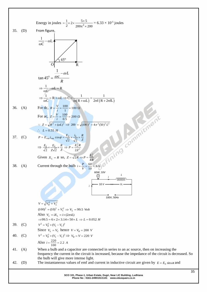
35. (D) From figure,
0
1
tan 45
Lc
R
1
L RC
1 1 1R L C
C R L 2 f R 2 fL
36. (A) For dc, 1001
100
i
VR
For ac, 2005.0
100
i
VZ
22 )( LRZ 2222 )50(4)100(200 L
HL 55.0
37. (C) Z
RiEiEP rmsrms
22cos 00
Z
R
Z
EE
22
00
2
20
2Z
REP
Given RX L so, RZ 2R
EP
4
20
38. (A) Current through the bulb AV
Pi 6
10
60
22LR VVV
222 )10()100( LV VoltVL 5.99
Also )2( LiiXV LL
L 5014.3265.99 HL 052.0
39. (C) 222 )( CLR VVVV
Since CL VV hence VVV R 200
40. (C) 222 )( CLR VVVV VVVR 220
Also Ai 2.2100
220
41. (A) When a bulb and a capacitor are connected in series to an ac source, then on increasing the
frequency the current in the circuit is increased, because the impedance of the circuit is decreased. So
the bulb will give more intense light.
42. (D) The instantaneous values of emf and current in inductive circuit are given by tEE sin0 and
i
10 V VL i
100V, 50Hz
L 60W, 10V
36 SCO 101, Phase-1, Urban Estate, Dugri, Near LIC Building, Ludhiana
Phone No : 0161-2490101/1101 www.edusquare.co.in
2sin0
tii respectively.
So,
2sinsin 00
titEEiPinst
2sincos
2cossinsin00
tttiE
ttiE cossin00
tiE 2sin2
100 )cossin22(sin ttt
Hence, angular frequency of instantaneous power is 2 .
43. (B) In RC series circuit voltage across the capacitor leads the voltage across the resistance by 2
44. (D) The voltage LV and CV are equal and opposite so voltmeter reading will be zero.
Also 25,30 CL XXR
So AR
V
XXR
Vi
CL
830
240
)( 22
45. (D) ttV 100cos100sin120 tV 200sin60
VV 60max and Hz100
46. (D) ;)()( 22CL XXRZ
101052000,10 3LXR L
10..1010502000
116
ZeiC
XC
Maximum current AZ
Vi 2
10
2000
Hence Airms 4.12
2
and 41.14rmsV 5.64 V
47. (A) Capacitance of wire
FFC 8.2108.220010014.0 66
For impedance of the circuit to be minimum CL XX C
L
2
12
623222 108.2)105()14.3(4
1
4
1
C
L
mHH 35.01035.0 3
48. (C) 2
4)4(4
2
4
2
4
2
2
2
dtt
dt
dtt
dt
dtii 12
22
4
22
4
2
2
t
t
Aiirms 32122
49. (C) Given ,5 CL XX this is the condition of resonance. So ,CL VV so net voltage across L and C
combination will be zero.
50. (A) At angular frequency , the current in RC circuit is given by
2
2 1
CR
Vi rmsrms
......(i)
Also
22
22
2
9
3
1
2
CR
V
C
R
Vi rmsrmsrms
......(ii)
From equation (i) and (ii) we get

37 SCO 101, Phase-1, Urban Estate, Dugri, Near LIC Building, Ludhiana
Phone No : 0161-2490101/1101 www.edusquare.co.in
5
3
1
53
22
2 R
C
CR
5
3
R
XC
51. (D) R
X
R
X
R
X
R
X CLoCL 60tantan
RXX CL 3
i.e. RXXRZ CL 22 )(
So average power 100
2002002
R
VP = 400 W
52. (B) 1516
2402rmsi
PR
254
100
i
VZ
Now 20)15()25( 2222 RZX L
HzLL
5
1
502
20202
53. (B) 2/, RXRX CL
2
12tan
R
RR
R
XX CL
)2/1(tan 1
Also RR
RXXRZ CL2
5
4)(
2222
54. (B)
55. (A)
56. (A) The choke coil can be used only in ac circuits, not in dc circuits, because for dc ( = 0) the
inductive reactance LXL of the coil is zero, only the resistance of the coil remains effective which
too is almost zero.
57. (B) Because power ,2 Ri if R = 0, then P = 0.
58. (A)
59. (A) A choke coil contains high inductance but negligible resistance, due to which power loss
becomes appreciably small.
60. (B) For purely capacitive circuit tee sin0
2sin
tii o i.e. current is ahead of emf by
2
61. (C)
62. (D)
63. (D) AZ
Vi 8.0
)1031000(4
4
232
64. (C) RXR
X
R
XL
LoL 145tantan
65. (A) For purely L-circuit P = 0
66. (A) At resonance LCR series circuit behaves as pure resistive circuit. For resistive circuit o0
67. (C) VoltVVVV CLR 5)1010()5()( 2222
68. (B) When dc is supplied 1001
100
i
VR
When ac is supplied 2005.0
100
i
VZ
69. (B) 222
cos
LR
R
Z
R
2222 )1.0()60(4)12(
12
30.0cos

38 SCO 101, Phase-1, Urban Estate, Dugri, Near LIC Building, Ludhiana
Phone No : 0161-2490101/1101 www.edusquare.co.in
70. (C)
71. (B)
72. (C) Impedance 10)6()8( 2222 XRZ
73. (C) o
R
L805.5
12
21.0502tan
74. (A) If the current is wattless then power is zero. Hence phase difference o90
2
12tan
R
RR
R
XX CL
)2/1(tan 1
Also RR
RXXRZ CL2
5
4)(
2222
75. (A) LC
f2
1
Cf
1
76. (B) In non resonant circuits
impedance 2
2
11
1
LC
R
Z
, with rise in frequency Z decreases i.e. current increases so circuit
behaves as capacitive circuit.
77. (B) VVVV LR 6.25656)16()20( 2222
78. (D) 22 )2.0502()20(
220
i A33.3
66
220
79. (A) Impedance of LCR circuit will be minimum at resonant frequency so LC
2
10
63 101.01012
1
Hz
2
105
80. (C) o
Z
R60
2
1
20
10cos
81. (A) Current in LC circuit becomes maximum when resonance occurs. So
sec/2005
1000
10251
11
6rad
LC
82. (B, D)
83. (A) 1046R
101052000 3LX L
1010502000
116C
XC
10)( 22CL XXRZ
Amplitude of current AZ
Vi 2
10
2000
84. (C)
85. (A)
86. (A)
87. (B)
88. (C)
89. (B)
90. (D)
91. (B) AV
Pi
s
ss 4.0
1011
104.43
3
92. (B) 100220
22000
p
s
p
s
V
V
N
N
93. (B)
39 SCO 101, Phase-1, Urban Estate, Dugri, Near LIC Building, Ludhiana
Phone No : 0161-2490101/1101 www.edusquare.co.in
94. (A)
95. (B) s
p
p
s
i
i
N
N or Ai
ip
p50
21
25
96. (C) voltsVN
NV
N
N
V
Vp
p
ss
p
s
p
s 12240200
10
97. (A) 500
5000
20 s
p
s
p
s V
N
N
V
V VVs 200
Frequency remains unchanged.
98. (A) VVV
kN
N
V
Vs
s
p
s
p
s 452
3
30
99. (A) 5
4
s
p
s
p
p
s
i
i
i
i
N
N
100. (D) VVVV sp 6,200
AiiiVP ssssout 5630
From Aii
i
i
V
Vp
p
s
p
p
s 15.05200
6
101. (B) VEEN
N
E
Es
ss
p
s
p40
20
100200
102. (D) Since all the losses are neglected.
So inout PP
103. (C)
104. (B) Aii
N
N
i
ip
p
p
s
s
p04.0
100
1
4
105. (B) 10:1: sp NN and VVs 1002005.0
VVVN
N
V
Vp
pp
s
p
s 101
10100
ampii
N
N
i
ip
p
p
s
s
p5,
1
10
5.0
106. (C)
107. (D) ampii
i
i
V
Vs
s
p
s
s
p05.0
522000
220
108. (B) Aii
i
V
Vs
p
s
s
p2
280
1404
109. (C) 8
100081000 sssss VViVP
400100
500
)8/1000( s
ss
p
s
pN
NN
N
V
V
110. (B) Aii
i
V
Vs
p
s
s
p2
280
1404

40 SCO 101, Phase-1, Urban Estate, Dugri, Near LIC Building, Ludhiana
Phone No : 0161-2490101/1101 www.edusquare.co.in
SOLUTIONS
1. (C)
2. (C) ID = dq d
dt dt q0sin2nt = 2nq0 cos2q0 cos2nt
3. (D) B = 10 –80 0
16
r dE 110 5.56 10 T
2 dt 2 9 10
4. (B)
5. (B)
6. (A)
7. (C) ID = dq dv
Cdt dt
or D
–6
Idv 1
dt C 10 = 106 V/s
8. (C) According to Ampere's law, when r > R B = 0 DI
2 r
9. (C) According to Ampere's law, when r > R B = 0 Dr
2
I
2 R
10. (B)
11. (B) c =
14
6
9 10
k 3 10
= 3 108 m/s
12. (A) 3 6x,t 10 sin3 10 (x – 3 108 t)
Comparing it with
x,t = asin 2
(x – vt)
2
= 3 106
or =
9
6
2 10
3 10
= 666 nm
13. (D)
14. (B)
15. (B)
16. (A)
17. (C)
18. (B)
19. (D)
20. (A) The green house effect would not have been possible without atmosphere. Hence temperature
would be lower.
21. (B)
22. (C)
23. (C)
24. (B)
25. (B)
26. (A)
27. (C)
28. (B)
29. (C)
30. (A)
PHYSICS BOOK-5 OBJECTIVE QUESTIONS
SOLUTIONS ELECTROMAGNETIC WAVES

41 SCO 101, Phase-1, Urban Estate, Dugri, Near LIC Building, Ludhiana
Phone No : 0161-2490101/1101 www.edusquare.co.in
31. (C)
32. (C)
33. (C) d
0
IdV I
dt C A
=
–3
–12
0.15 5 10
8.85 10 3.14 0.0144
= 1.873 109 V/s
34. (C) ID = IC = 0.15A
35. (B) No. of oscillations in coherence length
= 6
–7
l 0.0244.068 10 Hz
5.9 10
36. (D) The coherence time t = –11
8
l 0.0248 10
c 3 10
ls-
37. (D) IRMS = RMS
C
E
X = CERMS
= 300 10–10 230 = 6.9A
38. (A) ID = IC = 6.9A
39. (D) B0 = 0 D peak
2
I r
2 R
=
–7 –6
4
2 10 2 6.9 10
2 3.14 36 10
= 1.63 10–11T
40. (C)
8
7
C 3 107.5m
f 4 10
41. (C) T = 1
f =
7
1
4 10 = 0.025s
42. (C) Bm = m
8
E 750
C 3 10 = 2.5T Z-directiona
43. (A) = 2f = 2 4 10 = 8 107 rad/s.
44. (B) K = 2 2 3.14
0.8387.5
m–1
45. (C) power P = 5A = 103 8 20 = 1.6 105W
46. (B) F = PA =
54
8
SA 1.6 10F PA 5.33 10
c 3 10
47. (A) E = power time
= 1.6 105 3600 = 5.76 108J
48. (D) Isurface = P
A=
26
2 16
3.9 10
4 3.14 6.96 10
= 5.6 107 W/m2
49. (A) Iearth =
26
2 22
P 3.9 10
4 r 4 3.14 2.25 10
= 1.38 103
W/m2
50. (B) Area through which the energy of beam passes
= (6.328 10–7)2 = 4 10–13 m2
I =
–3
–13
P 10
A 4 10
= 2.5 109 W/m2
51. (B) Iav =
2
0 0c E
2
=
8 –12 23 10 8.85 10 36
2
= 1.72 W/m2

42 SCO 101, Phase-1, Urban Estate, Dugri, Near LIC Building, Ludhiana
Phone No : 0161-2490101/1101 www.edusquare.co.in
52. (D) B =
20 0 dEd
2 R 4 dt
=
–7 –122 10 8.85 10 3.14 0.01 .20
4 0.15
= 1.85 10–18T
53. (A) Sav = 2
0 02
P 1cE
4 R 2
0 2
0
PE
2 R c
= –12 8
3
2 3.14 100 8.85 10 3 10
= 1.34 V/m
54. (D) In one second
P =
–4
av
8
2S A2U 2 6 40 10
c c 3 10
= 1.6 10–10 Kg-m/s
55. (D) Momentum per sec is force
F = 1.6 10–10 Newton
56. (C) Wavelength of electromagnetic wave
8–2
10
c 3 101.5 10
v 2 10
= 1.5 cm
Hence correct answer will be (C)
57. (D) Energy density at 3.5m is given by
2
0 m
1u E
2
= 2–121
8.85 10 62.62
= 1.73 10–8
Hence the correct answer will be(D)
58. (A) The r.m.s. value of conduction current
V V
I 2 nCV1Z
2 nC
or I = 2 3.14 50 100 10–12 230
= 7.2 10–6 A
Hence the correct answer will be(A)
59. (B) Height of transmitting antenna
h =
232
6
128 10d1280m
2Re 2 6.4 10
Hence the correct answer will be(B)
60. (A) The area of transmission surrounding the T.V. tower
A = d2 = (2hRe)
A h
Hence the correct answer will be(A)
61. (A)
62. (C)
63. (A)
64. (D)