physics - board of studies 433 2003 higher school ... a transformer allows the neon ... calculate...
TRANSCRIPT

General Instructions
• Reading time – 5 minutes
• Working time – 3 hours
• Write using black or blue pen
• Draw diagrams using pencil
• Board-approved calculators maybe used
• A data sheet, formulae sheets andPeriodic Table are provided atthe back of this paper
• Write your Centre Number andStudent Number at the top ofpages 13, 17, 21 and 25
Total marks – 100
Pages 2–28
75 marks
This section has two parts, Part A and Part B
Part A – 15 marks
• Attempt Questions 1–15
• Allow about 30 minutes for this part
Part B – 60 marks
• Attempt Questions 16–27
• Allow about 1 hour and 45 minutes for this part
Pages 29–42
25 marks
• Attempt ONE question from Questions 28–32
• Allow about 45 minutes for this section
Section II
Section I
Physics
433
2003H I G H E R S C H O O L C E R T I F I C AT E
E X A M I N AT I O N

– 2 –
Section I75 marks
Part A – 15 marksAttempt Questions 1–15Allow about 30 minutes for this part
Use the multiple-choice answer sheet.
Select the alternative A, B, C or D that best answers the question. Fill in the response ovalcompletely.
Sample: 2 + 4 = (A) 2 (B) 6 (C) 8 (D) 9
A B C D
If you think you have made a mistake, put a cross through the incorrect answer and fill in thenew answer.
A B C D
If you change your mind and have crossed out what you consider to be the correct answer, thenindicate the correct answer by writing the word correct and drawing an arrow as follows.
correct
A B C D
1 The weight of an astronaut on the Moon is 1–6
of her weight on Earth.
What is the acceleration due to gravity on the Moon?
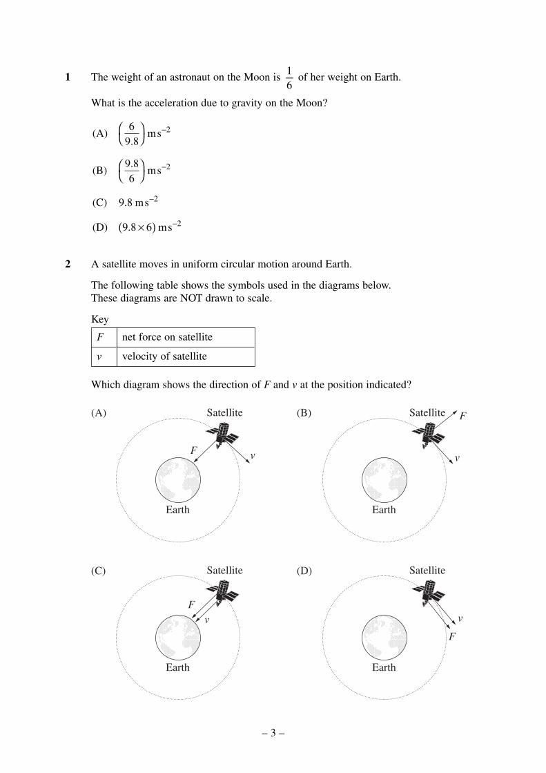
2 A satellite moves in uniform circular motion around Earth.
The following table shows the symbols used in the diagrams below. These diagrams are NOT drawn to scale.
Key
Which diagram shows the direction of F and v at the position indicated?
Earth
Satellite
F v
v
Earth
Satellite
F
Earth
Satellite F
v
Earth
Satellite
F
v
(A) (B)
(C) (D)
net force on satellite
velocity of satellite
F
v
(A) ms
(B) ms
(C) 9.8 ms
(D) ms
69 8
9 86
9 8 6
2
2
2
2
.
.
.
×( )
−
−
−
−
– 3 –

3 For a satellite moving in uniform circular motion around Earth, the centripetal force isprovided by the gravitational force.
The mass of Earth is ME.
The mass of the satellite is MS.
The distance of the satellite from the centre of Earth is d .
Which of the following equations should be used to calculate the speed of this satellite?
4 Two planets, X and Y, travel around a star in the same direction, in circular orbits.
Planet X completes one revolution about the star in time T. The radii of the orbits are inthe ratio 1 : 4.
How many revolutions does planet Y make about the star in the same time T?
(A) 1–8 revolution
(B) 1–2 revolution
(C) 2 revolutions
(D) 8 revolutions
X
Y
r
4r
(A)
(B)
(C)
(D)
E
E
E
E S
vGM
d
vGM
d
vGM
d
vGM M
d
=
=
=
=
2
– 4 –
5 An astronaut set out in a spaceship from Earth orbit to travel to a distant star in ourgalaxy. The spaceship travelled at a speed of 0.8 c. When the spaceship reached the starthe on-board clock showed the astronaut that the journey took 10 years.
An identical clock remained on Earth. What time in years had elapsed on this clock whenseen from the astronaut’s spaceship?
(A) 3.6
(B) 6.0
(C) 10.0
(D) 16.7
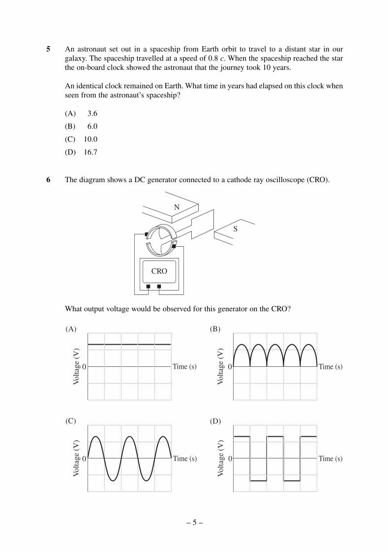
6 The diagram shows a DC generator connected to a cathode ray oscilloscope (CRO).
What output voltage would be observed for this generator on the CRO?
(A) (B)
(C) (D)
Time (s)
Vol
tage
(V
)
0 Time (s)
Vol
tage
(V
)
0
Vol
tage
(V
)
Time (s)0 Time (s)
Vol
tage
(V
)
0
N
S
CRO
– 5 –

7 A non-magnetic metal disk is balanced on a support as shown in the diagram below. Thedisk is initially stationary. A magnet is moved in a circular path just above the surface ofthe disk, without touching it.
As a result of this movement the disk begins to rotate in the same direction as the magnet.
The observed effect demonstrates the principle most applicable to the operation of the
(A) DC motor.
(B) galvanometer.
(C) generator.
(D) induction motor.
8 A neon sign requires a 6000 V supply for its operation. A transformer allows the neonsign to operate from a 240 V supply.
What is the ratio of the number of secondary turns to the number of primary turns for thetransformer?
(A) 1 : 40
(B) 1 : 25
(C) 25 : 1
(D) 40 : 1
S
N
Path
Disk
– 6 –
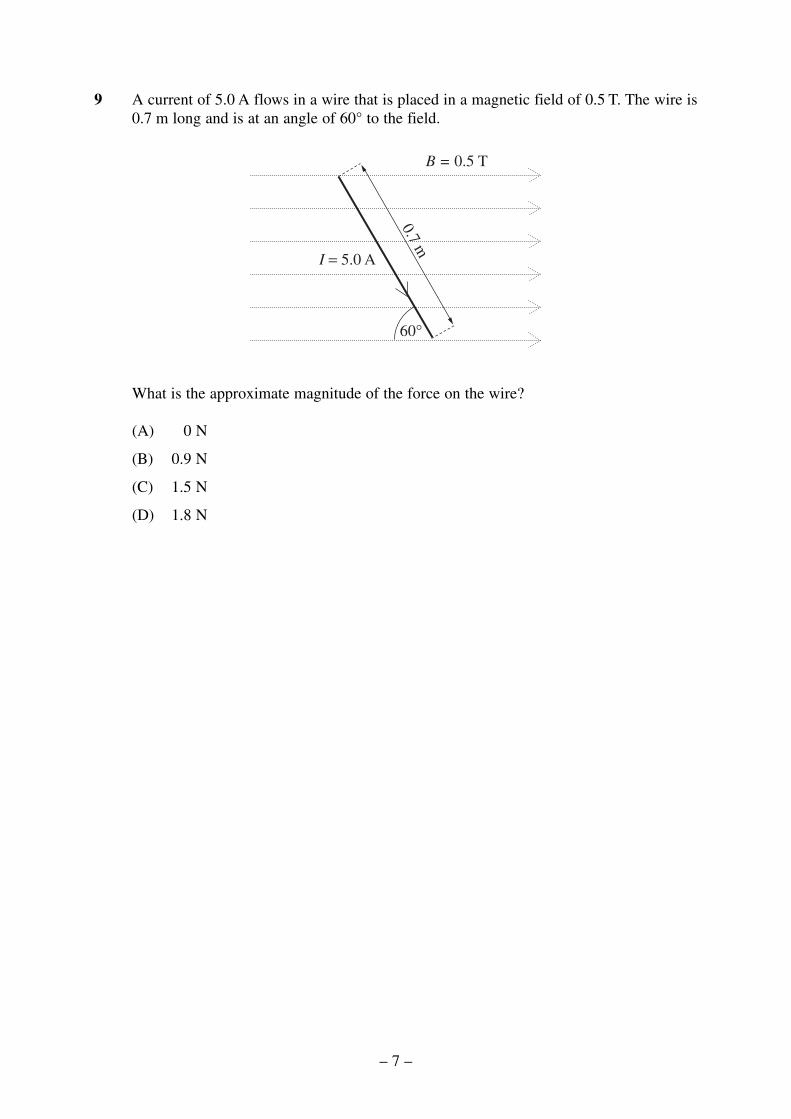
9 A current of 5.0 A flows in a wire that is placed in a magnetic field of 0.5 T. The wire is0.7 m long and is at an angle of 60° to the field.
What is the approximate magnitude of the force on the wire?
(A) 0 N
(B) 0.9 N
(C) 1.5 N
(D) 1.8 N
I = 5.0 A
60°
0.7 m
B = 0.5 T
– 7 –
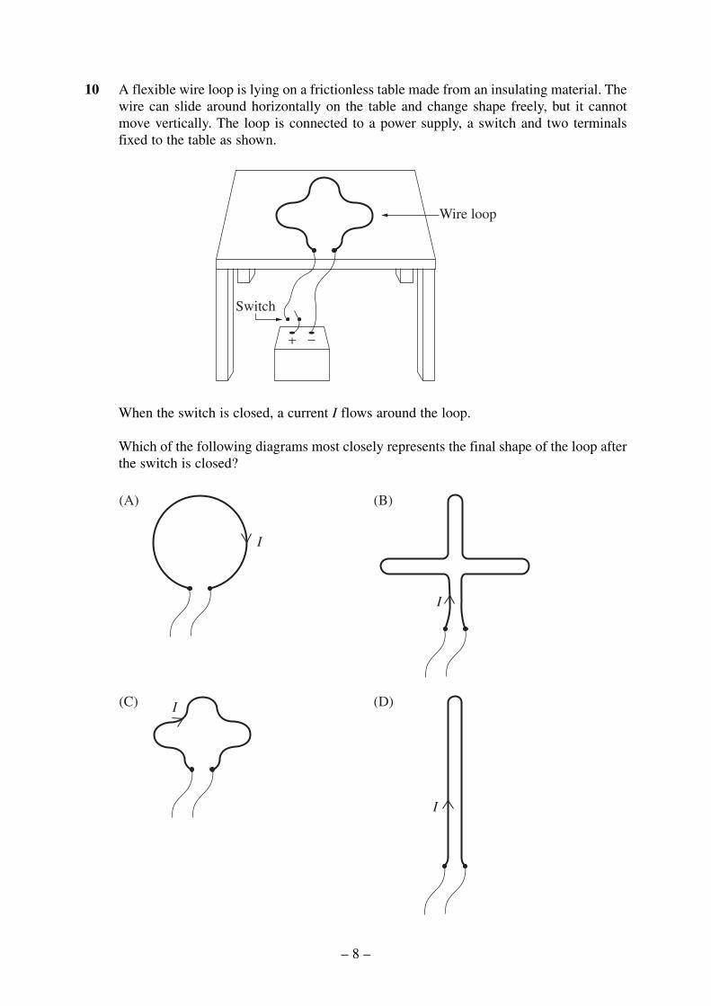
10 A flexible wire loop is lying on a frictionless table made from an insulating material. Thewire can slide around horizontally on the table and change shape freely, but it cannotmove vertically. The loop is connected to a power supply, a switch and two terminalsfixed to the table as shown.
When the switch is closed, a current I flows around the loop.
Which of the following diagrams most closely represents the final shape of the loop afterthe switch is closed?
(A) (B)
(C) (D)
I
I
I
I
Wire loop
Switch
– 8 –
11 Which of the following did the Braggs investigate using X-ray diffraction?
(A) Cathode rays
(B) Crystal structure
(C) Photoelectric effect
(D) Superconductivity
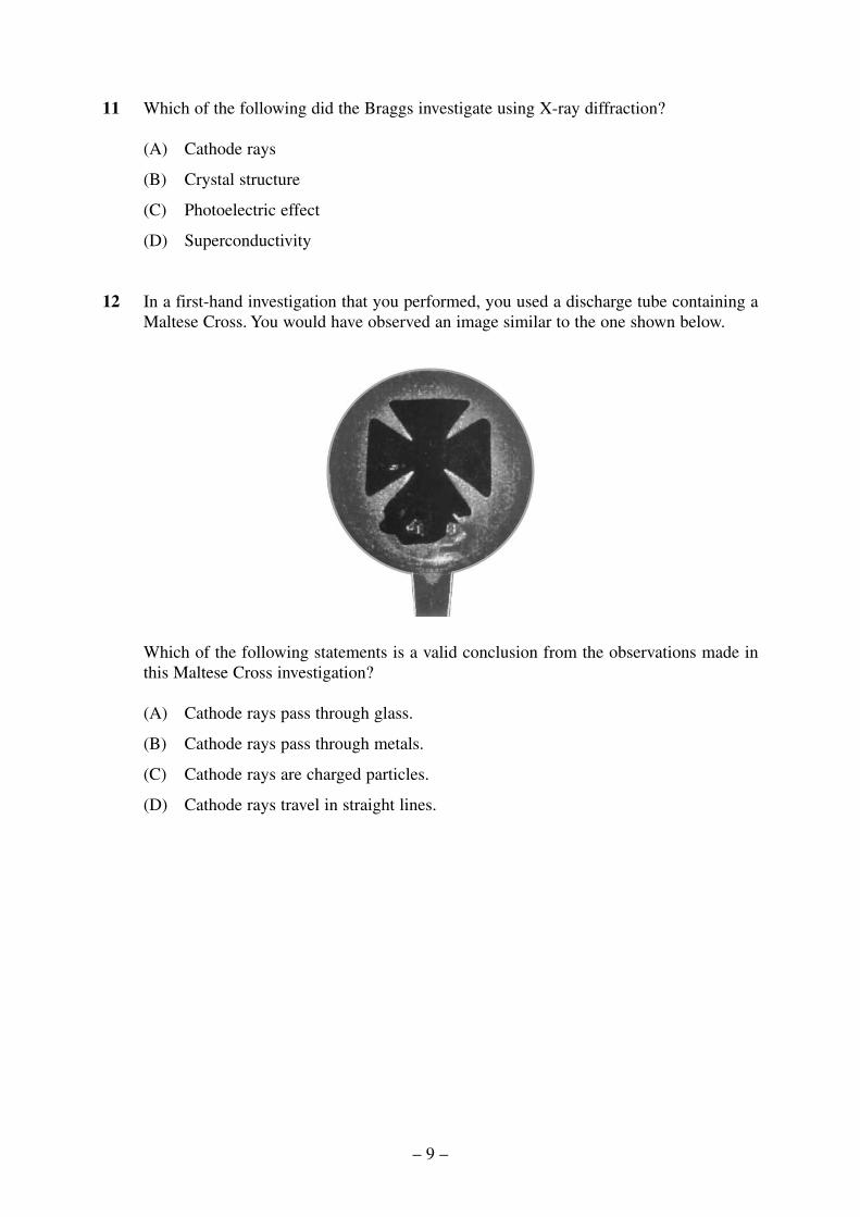
12 In a first-hand investigation that you performed, you used a discharge tube containing aMaltese Cross. You would have observed an image similar to the one shown below.
Which of the following statements is a valid conclusion from the observations made inthis Maltese Cross investigation?
(A) Cathode rays pass through glass.
(B) Cathode rays pass through metals.
(C) Cathode rays are charged particles.
(D) Cathode rays travel in straight lines.
– 9 –

13 An n-type semiconductor is produced when silicon crystal is doped with small quantitiesof phosphorus.
How will this doping change the crystal’s electrical conductivity?
(A) The conductivity will decrease because there are fewer holes in the valence band.
(B) The conductivity will increase because there are more holes in the valence band.
(C) The conductivity will decrease because there are fewer electrons in the conductionband.
(D) The conductivity will increase because there are more electrons in the conductionband.
14 Heinrich Hertz used a set-up similar to the one shown below to investigate the productionand detection of electromagnetic radiation.
A glass sheet was placed between the transmitter and receiver.
Which of the following observations is consistent with the photoelectric effect that Hertzproduced?
(A) Radio waves were blocked when the glass sheet was in place.
(B) Ultraviolet waves were blocked when the glass sheet was in place.
(C) The maximum spark length was longer when the glass sheet was in place.
(D) The maximum spark length was shorter when the glass sheet was in place.
Transmitter Receiver
High voltagesource of
radio waves
– 10 –

15 A positively-charged ion travelling at 250 m s−1 is fired between two parallel chargedplates, M and N. There is also a magnetic field present in the region between the twoplates. The direction of the magnetic field is into the page as shown. The ion is travellingperpendicular to both the electric and the magnetic fields.
The electric field between the plates has a magnitude of 200 V m−1. The magnetic fieldis adjusted so that the ion passes through undeflected.
What is the magnitude of the adjusted magnetic field, and the polarity of the M terminalrelative to the N terminal?
Polarity of M relative to N
positive
negative
positive
negative
Magnitude of magneticfield (teslas)
0.8
0.8
1.25
1.25
(A)
(B)
(C)
(D)
M
N
– 11 –

BLANK PAGE
© Board of Studies NSW 2003
– 12 –

Section I (continued)
Part B – 60 marksAttempt Questions 16–27Allow about 1 hour and 45 minutes for this part
Answer the questions in the spaces provided.
Show all relevant working in questions involving calculations.
Question 16 (6 marks)
Please turn over
2003 HIGHER SCHOOL CERTIFICATE EXAMINATION
Physics
– 13 –434
Centre Number
Student Number
Question 16 (6 marks)
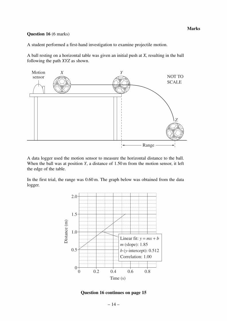
A student performed a first-hand investigation to examine projectile motion.
A ball resting on a horizontal table was given an initial push at X, resulting in the ballfollowing the path XYZ as shown.
A data logger used the motion sensor to measure the horizontal distance to the ball.When the ball was at position Y, a distance of 1.50 m from the motion sensor, it leftthe edge of the table.
In the first trial, the range was 0.60 m. The graph below was obtained from the datalogger.
Question 16 continues on page 15
2.0
1.5
1.0
0.5
00 0.2 0.4 0.6 0.8
Linear fit: y = mx + bm (slope): 1.85b (y-intercept): 0.512Correlation: 1.00
Time (s)
Dis
tanc
e (m
)
Range
Motionsensor
X Y
Z
NOT TOSCALE
– 14 –
Marks

Question 16 (continued)
(a) For this trial, determine the horizontal speed of the ball as it left the edge ofthe table.
...............................................................................................................................
...............................................................................................................................
(b) The experiment was repeated with the ball leaving the table at different speeds.Graph the relationship between the range and the horizontal speed at Y. Identifyon your graph the results from the first trial.
(c) The apparatus described in this first-hand investigation was used to carry out anidentical experiment on another planet where the acceleration due to gravity isless than that on Earth.
The horizontal speed of the ball as it left the table on the planet was the same asin part (a). Compare the range of the ball on the planet to that on Earth. Explainyour answer.
...............................................................................................................................
...............................................................................................................................
...............................................................................................................................
...............................................................................................................................
End of Question 16
2
0
3
1
– 15 –
Marks

Question 17 (6 marks)
A satellite of mass 150 kg is launched from Earth’s surface into a uniform circularorbit of radius 7.5 × 10⁶ m.
(a) Calculate the magnitude of the gravitational potential energy Ep of the satellite.
...............................................................................................................................
...............................................................................................................................
(b) From this uniform circular orbit, the satellite can escape Earth’s gravitationalfield when its kinetic energy is equal to the magnitude of the gravitationalpotential energy.
Use this relationship to calculate the escape velocity of the satellite.
...............................................................................................................................
...............................................................................................................................
...............................................................................................................................
...............................................................................................................................
...............................................................................................................................
...............................................................................................................................
...............................................................................................................................
...............................................................................................................................
(c) Discuss the effect of Earth’s rotational motion on the launch of this satellite.
...............................................................................................................................
...............................................................................................................................
...............................................................................................................................
...............................................................................................................................
2
3
1
– 16 –
Marks
© Board of Studies NSW 2003

Section I – Part B (continued)
MarksQuestion 18 (6 marks)
Michelson and Morley set up an experiment to measure the velocity of Earth relativeto the aether.
(a) Outline TWO features of the aether model for the transmission of light.
...............................................................................................................................
...............................................................................................................................
...............................................................................................................................
...............................................................................................................................
(b) Recount the Michelson and Morley experiment, which attempted to measure therelative velocity of Earth through the aether, and describe the results theyanticipated.
...............................................................................................................................
...............................................................................................................................
...............................................................................................................................
...............................................................................................................................
...............................................................................................................................
...............................................................................................................................
...............................................................................................................................
...............................................................................................................................
...............................................................................................................................
...............................................................................................................................
4
2
2003 HIGHER SCHOOL CERTIFICATE EXAMINATION
Physics
– 17 –435
Centre Number
Student Number

Question 19 (3 marks)
Two straight copper wires are suspended so that their lower ends dip into a conductingsalt solution in a beaker as shown. The length of the straight section of each wireabove the conducting salt solution is 35 cm and they are placed 1.5 cm apart. The endsof the wire do not touch the bottom of the beaker. The two wires are connected to aDC power supply.
A current of 2 amperes flows from the battery. Calculate the magnitude and directionof the initial force on each wire.
.........................................................................................................................................
.........................................................................................................................................
.........................................................................................................................................
.........................................................................................................................................
.........................................................................................................................................
.........................................................................................................................................
Conductingsalt solution
35 cm
1.5 cm
NOT TOSCALE
3
– 18 –
Marks

Question 20 (4 marks)
Two solenoids (coils) with hollow cores are suspended using string so that they arehanging in the positions shown below. The solenoids are free to move in a pendulummotion.
In the first investigation shown in Figure 1, a strong bar magnet is moved towards thesolenoid until the north end of the magnet enters the solenoid and then the motion ofthe magnet is stopped.
In the second investigation, shown in Figure 2, a thick copper wire is connectedbetween the two terminals, A and B, at the ends of the solenoid. The motion of themagnet is repeated exactly in this second investigation.
Explain the effect of the motion of the magnet on the solenoid in the two investigations.
.........................................................................................................................................
.........................................................................................................................................
.........................................................................................................................................
.........................................................................................................................................
.........................................................................................................................................
.........................................................................................................................................
.........................................................................................................................................
.........................................................................................................................................
Support
A B
N S
Support
A B
N S
Figure 1 – First investigation Figure 2 – Second investigation
Copper wire
4
– 19 –
Marks

BLANK PAGE
© Board of Studies NSW 2003
– 20 –

Section I – Part B (continued)
MarksQuestion 21 (5 marks)
(a) Explain the relationship between the current in the primary coil and the currentin the secondary coil of an ideal step-down transformer in relation to theconservation of energy.
...............................................................................................................................
...............................................................................................................................
...............................................................................................................................
...............................................................................................................................
...............................................................................................................................
...............................................................................................................................
(b) Explain why a transformer will work in an AC circuit but not in a DC circuit.
...............................................................................................................................
...............................................................................................................................
...............................................................................................................................
...............................................................................................................................
2
3
2003 HIGHER SCHOOL CERTIFICATE EXAMINATION
Physics
– 21 –436
Centre Number
Student Number

Question 22 (5 marks)
Describe a first-hand investigation to demonstrate the effect on a generated electriccurrent when the strength of the magnet is varied.
In your description, include:
• a labelled sketch of the experimental set-up;
• how you varied the magnetic field strength;
• how other variables were controlled.
.........................................................................................................................................
.........................................................................................................................................
.........................................................................................................................................
.........................................................................................................................................
.........................................................................................................................................
.........................................................................................................................................
.........................................................................................................................................
.........................................................................................................................................
.........................................................................................................................................
.........................................................................................................................................
5
– 22 –
Marks
Question 23 (6 marks)
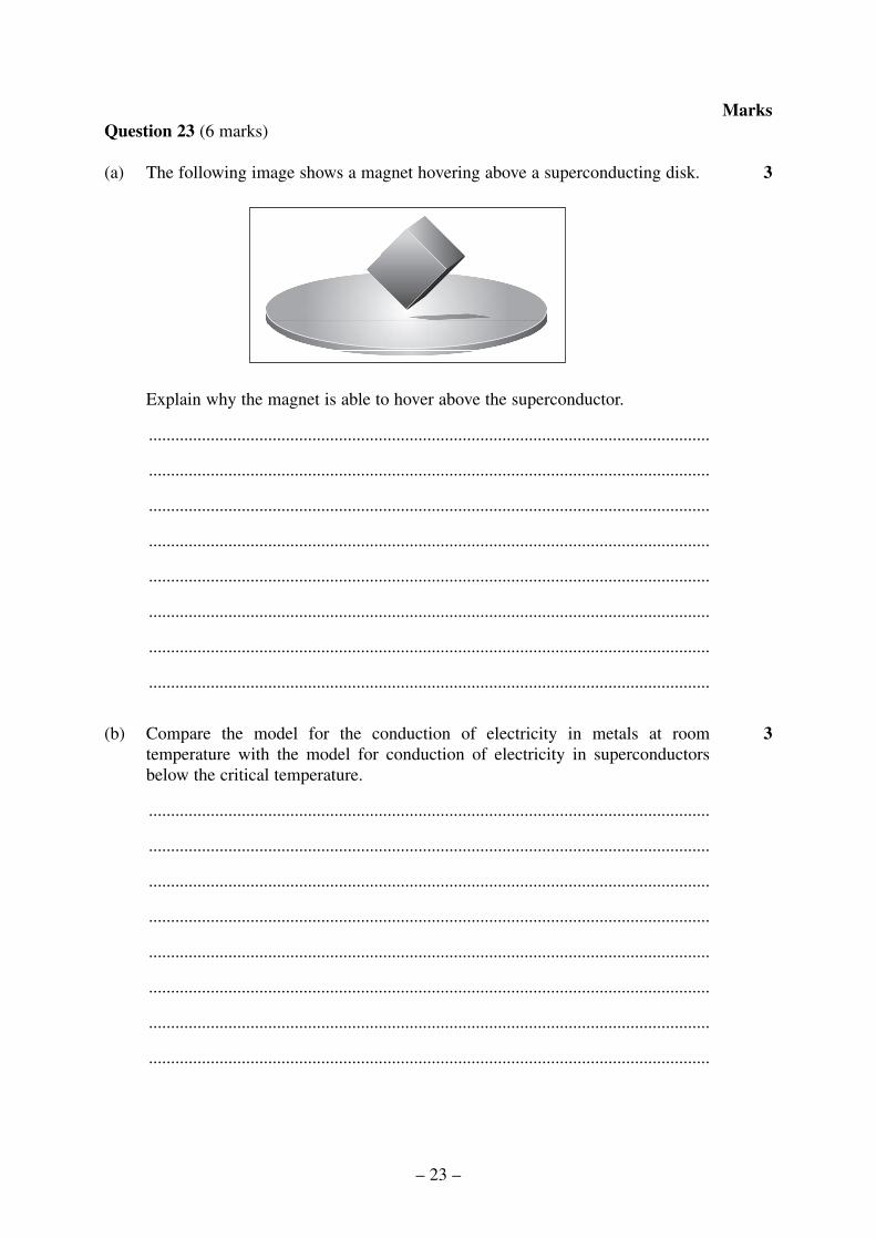
(a) The following image shows a magnet hovering above a superconducting disk.
Explain why the magnet is able to hover above the superconductor.
...............................................................................................................................
...............................................................................................................................
...............................................................................................................................
...............................................................................................................................
...............................................................................................................................
...............................................................................................................................
...............................................................................................................................
...............................................................................................................................
(b) Compare the model for the conduction of electricity in metals at roomtemperature with the model for conduction of electricity in superconductorsbelow the critical temperature.
...............................................................................................................................
...............................................................................................................................
...............................................................................................................................
...............................................................................................................................
...............................................................................................................................
...............................................................................................................................
...............................................................................................................................
...............................................................................................................................
3
3
– 23 –
Marks

BLANK PAGE
© Board of Studies NSW 2003
– 24 –

Section I – Part B (continued)
MarksQuestion 24 (4 marks)
Outline Thomson’s experiment to measure the charge/mass ratio of an electron.
.........................................................................................................................................
.........................................................................................................................................
.........................................................................................................................................
.........................................................................................................................................
.........................................................................................................................................
.........................................................................................................................................
.........................................................................................................................................
.........................................................................................................................................
.........................................................................................................................................
.........................................................................................................................................
4
2003 HIGHER SCHOOL CERTIFICATE EXAMINATION
Physics
– 25 –437
Centre Number
Student Number

Question 25 (5 marks)
A physics student was conducting an investigation on the photoelectric effect. Thestudent used an infrared laser with a wavelength of 1.55 × 10⁻⁶ m for this investigation.
(a) Calculate the energy of a photon from this laser.
...............................................................................................................................
...............................................................................................................................
...............................................................................................................................
...............................................................................................................................
(b) When the laser light was shone onto a photo-cell, no current was detected. Thestudent increased the intensity of the light but still detected no current.
Explain this observation.
...............................................................................................................................
...............................................................................................................................
...............................................................................................................................
...............................................................................................................................
...............................................................................................................................
...............................................................................................................................
3
2
– 26 –
Marks

Question 26 (6 marks)
Describe Einstein’s contributions to Special Relativity and to Quantum Theory andhow these contributions changed the direction of scientific thinking in the TwentiethCentury.
.........................................................................................................................................
.........................................................................................................................................
.........................................................................................................................................
.........................................................................................................................................
.........................................................................................................................................
.........................................................................................................................................
.........................................................................................................................................
.........................................................................................................................................
.........................................................................................................................................
.........................................................................................................................................
.........................................................................................................................................
.........................................................................................................................................
.........................................................................................................................................
.........................................................................................................................................
6
– 27 –
Marks

Question 27 (4 marks)
In a particle accelerator called a synchrotron, magnetic fields are used to control themotion of an electron so that it follows a circular path of fixed radius.
Describe the changes required in the magnetic field to accelerate an electron to nearthe speed of light. Support your answer with appropriate mathematical relationships.
.........................................................................................................................................
.........................................................................................................................................
.........................................................................................................................................
.........................................................................................................................................
.........................................................................................................................................
.........................................................................................................................................
.........................................................................................................................................
.........................................................................................................................................
.........................................................................................................................................
.........................................................................................................................................
4
– 28 –
Marks
© Board of Studies NSW 2003
Section II
25 marksAttempt ONE question from Questions 28–32Allow about 45 minutes for this section
Answer the question in a writing booklet. Extra writing booklets are available.
Show all relevant working in questions involving calculations.
Pages
Question 28 Geophysics ........................................................................... 31–33
Question 29 Medical Physics ................................................................... 34–35
Question 30 Astrophysics ......................................................................... 36–38
Question 31 From Quanta to Quarks ....................................................... 39–40
Question 32 The Age of Silicon ............................................................... 41–42
2003 HIGHER SCHOOL CERTIFICATE EXAMINATION
Physics
– 29 –438

BLANK PAGE
– 30 –
Question 28 — Geophysics (25 marks)
(a) (i) Identify THREE principal methods used by geophysicists to investigatethe structure of Earth and the properties of Earth materials.
(ii) Describe the role that geophysicists play in the monitoring of nucleartest-ban treaties.
(b) Summarise the geophysical evidence that supports the theory of plate tectonics.
(c) (i) Describe how absorption and reflection of radiation can provideinformation about a reflecting surface.
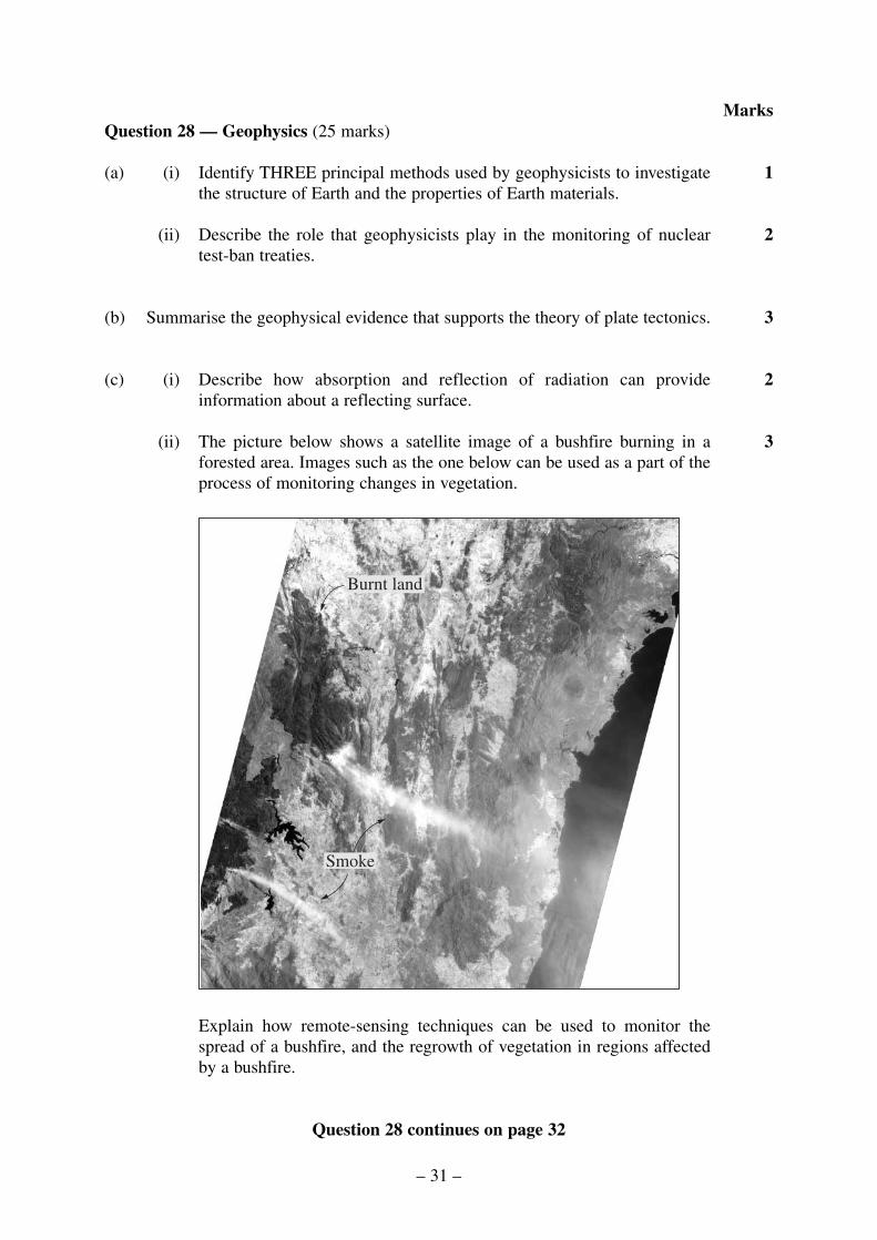
(ii) The picture below shows a satellite image of a bushfire burning in aforested area. Images such as the one below can be used as a part of theprocess of monitoring changes in vegetation.
Explain how remote-sensing techniques can be used to monitor thespread of a bushfire, and the regrowth of vegetation in regions affectedby a bushfire.
Question 28 continues on page 32
Smoke
Burnt land
3
2
3
2
1
– 31 –
Marks

Question 28 (continued)
(d) (i) Outline the structure and function of a geophone.
(ii) The method of seismic refraction is depicted in the diagram below. Aseries of eight geophones, G1 to G8, are arranged in a straight line alonglevel ground. They are each separated by a distance of 10 m.
At a distance of 20 m from the first geophone, a hammer is used to strikethe ground to produce seismic waves.
The geophones are attached to a seismograph that records the time ofarrival of the waves after the hammer strikes the ground.
The data from the geophones are analysed and the arrival times of thedirect and refracted waves that reach each geophone are recorded. Thesedata are shown in the graph on page 33. On the graph, a circle representsthe arrival of the first wave to reach a geophone, and a square representsthe arrival time of the second wave to reach a geophone. The points onthe graph associated with the direct seismic wave and the refractedseismic wave are shown.
Question 28 continues on page 33
G1 G2 G3 G4 G5 G6 G7 G8
Hammer Geophones
Soft rock
Hard rock
20 m 10 m
2
– 32 –
Marks

Question 28 (continued)
(1) Explain why the line for the refracted wave crosses the line for thedirect wave on the graph.
(2) From the graph, calculate the speed of the direct wave in the softrock layer.
(e) Outline the application of Newton’s theory of universal gravitation to the fieldof geophysics, and discuss how information obtained from gravity surveys hasled to a greater understanding of the structure of Earth.
End of Question 28
8
2
2
Refracted wave
Direct wave
0 10 20G1 G2 G3 G4 G5 G6 G7 G8
30 40 50 60 70 80 90
0.16
0.14
0.12
0.10
0.08
0.06
0.04
0.02
0
Distance to geophones (metres)
Tim
e af
ter
ham
mer
impa
ct (
seco
nd)
Time of arrival of first wave at geophone
Time of arrival of second wave at geophone
Legend
– 33 –
Marks

Question 29 — Medical Physics (25 marks)
(a) (i) Identify the property of the hydrogen nucleus that makes it useful inmagnetic resonance imaging.
(ii) Describe how X-rays are produced when electrons strike the anode in anX-ray tube.
(b) Outline the production of gamma rays and their use in the diagnostic procedureof positron emission tomography (PET).
(c) This question refers to the bone scan of a person with cancer, and a chest X-rayof a healthy person.
Bone-scan image X-ray image
(i) Compare how radiation is used to produce a bone scan image and anX-ray image.
(ii) Describe how a bone scan is able to provide information that an X-raycannot provide.
Question 29 continues on page 35
2
3
3
2
1
– 34 –
Marks
Awaiting Copyright Clearance
Awaiting Copyright Clearance

Question 29 (continued)
(d) The table below shows the speed of sound in, and density of, several differenttissues.
(i) Calculate the acoustic impedance of kidney tissue.
(ii) Ultrasound travelling through kidney tissue in the body encounters adifferent type of tissue. Identify the type of tissue that will result in thegreatest proportion of the incident pulse being reflected at the boundarybetween the kidney and the other tissue. Justify your choice.
(iii) Describe the properties of ultrasound that led to its use in themeasurement of bone density.
(e) An understanding of the properties of electrons, and our ability to control theirbehaviour, have played key roles in the development of CAT scans and positronemission tomography imaging technologies.
Justify this statement with reference to the production and display of imagesused for medical diagnosis.
End of Question 29
8
3
2
1
Density (kg m−3)
952
1025
1038
1065
1076
Speed of sound in tissue (m s−1)
1450
1570
1560
1550
1580
Tissue
Fat
Blood
Kidney
Liver
Muscle
– 35 –
Marks

Question 30 — Astrophysics (25 marks)
(a) (i) Define the term resolution of a telescope.
(ii) Describe ONE method by which the resolution of a ground-based systemcan be improved.
(b) An H-R diagram for the globular cluster M3 is shown below.
The stars in the Lyrae gap have an absolute magnitude of 0.6. Use thisinformation and their position on the H-R diagram to determine the distance ofM3 from Earth.
Question 30 continues on page 37
Lyrae Gap
12
14
16
18
20
10 000 7 500 5 000
Temperature (K)
App
aren
t mag
nitu
de
3
2
1
– 36 –
Marks
Question 30 (continued)
(c) The diagram below is a comparison of the spectrum of quasar 3C 273 and aspectrum from a light source on Earth.
(i) From this comparison, identify the feature of the quasar spectrum that isrepresentative of the spectra produced by quasars.
(ii) The spectra above are both examples of absorption spectra.
(1) Account for the production of a star’s absorption spectrum.
(2) Describe how a spectrum from a star can provide information on thesurface temperature of that star. Give a specific example to illustrateyour answer.
Question 30 continues on page 38
2
2
1
– 37 –
Marks
Awaiting Copyright Clearance

Question 30 (continued)
(d) The H-R diagram for a cluster is shown below.
(i) Why is the cluster considered young?
(ii) Stars X and Z are both part of the same cluster but have different mainsequence nuclear reactions and different evolutionary pathways.
(1) Contrast the fusion reactions in star X and star Z.
(2) Predict TWO possible evolutionary pathways for star X.
(e) Evaluate the impact of studying the visible spectrum of light on our understandingof celestial objects.
End of Question 30
8
3
2
1
Main sequence
Star X
Star Z
O B A F G K MSpectral class
1 000 000
10 000
100
1
0.01
0.0001
0. 000 001
Lum
inos
ity (
Sun
= 1)
Apparent m
agnitude
−5
+5
+10
+15
+20
0
−10
Cluster
– 38 –
Marks
Question 31 — From Quanta to Quarks (25 marks)
(a) (i) Identify the structure of the Rutherford model of the atom.
(ii) Describe how Bohr refined Rutherford’s model of the hydrogen atom.
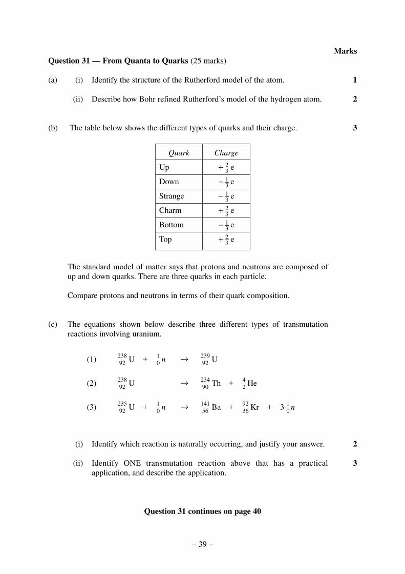
(b) The table below shows the different types of quarks and their charge.
The standard model of matter says that protons and neutrons are composed ofup and down quarks. There are three quarks in each particle.
Compare protons and neutrons in terms of their quark composition.
(c) The equations shown below describe three different types of transmutationreactions involving uranium.
(i) Identify which reaction is naturally occurring, and justify your answer.
(ii) Identify ONE transmutation reaction above that has a practicalapplication, and describe the application.
Question 31 continues on page 40
3
2
n103+Kr92
36+Ba141
56→n1
0+U235
92(3)
He42
+Th23490
→U23892(2)
U23992
→n10
+U23892(1)
Charge
+ 2–3 e
− 1–3 e
− 1–3 e
+ 2–3 e
− 1–3 e
+ 2–3 e
Quark
Up
Down
Strange
Charm
Bottom
Top
3
2
1
– 39 –
Marks

Question 31 (continued)
(d) The two graphs below show the gravitational and electrostatic forces actingbetween two protons in the nucleus of an atom.
(i) If the distance between protons in a nucleus is 1.0 × 10⁻¹⁵ m, determineboth the gravitational and the electrostatic force at this distance.
(ii) Explain why these two forces cannot explain the stability of the nucleus,and why there is a need for the strong nuclear force.
(iii) Describe TWO properties of the strong nuclear force.
(e) Describe the requirements for a nuclear fission explosion, and describe howthese are controlled in a nuclear reactor.
End of Question 31
8
2
2
2
1000
800
600
400
200
00 1 2 3 4
Electrostatic force
Nucleon distance d (× 10−15 m)
F (
N)
0−1−2−3−4−5−6−7−8
0 1 2 3 4
Gravitational force
Nucleon distance d (× 10−15 m)
F (
× 10
−34 N
)
– 40 –
Marks

Question 32 — The Age of Silicon (25 marks)
(a) (i) Identify ONE electronic system that is digital, and ONE electronic systemthat is analogue.
(ii) Use diagrams to describe the variation between digital and analoguevoltage outputs with time.
(b) Construct a truth table showing the outputs at P, Q and R for each of the possibleinput states of A and B in the following circuit.
(c) The graph below shows how the density of transistors on a silicon chip hasincreased over the last 30 years.
(i) Use the data in the graph to predict the change in computer performancefrom 1970 to 2005. Justify your answer.
(ii) Discuss the validity of using the graph to predict computer performanceup to 2060.
Question 32 continues on page 42
2
3
1970 1980 1990 2000 2010103
104
105
106
107
108
Year
Tra
nsis
tor
dens
ity (
cm−2
)
Gate 3
Gate 1 Gate 2 R
Q
A
B
P
Gate 1 InverterGate 2 ORGate 3 AND
3
2
1
– 41 –
Marks

Question 32 (continued)
(d) The circuit below uses a thermistor as a temperature sensor to control theoperation of a relay. The relay will close when the voltage across the relay coilis greater than 6 volts. The resistance of the thermistor, RTHERM, is given in thegraph.
(i) Calculate the voltage at point A at a temperature of 15°C. Neglect theeffect of the 100 kΩ resistor and the operational amplifier on the voltageat point A.
(ii) Determine the value of R so that the relay will close only when thetemperature falls below 15°C.
(e) Describe and compare the physical principles underlying the operation of inputand output transducers. Use an analogue ammeter and a solar cell as examples.
End of paper
8
3
3
0 5 10 15 20 25
1.0
1.5
2.0
2.5
3.0
Temperature (°C)
RT
HE
RM
(kΩ
)
22 kΩ100 kΩ
−
+
R
A
ThermistorRelay coil
+12 V
– 42 –
Marks

BLANK PAGE
– 43 –

BLANK PAGE
© Board of Studies NSW 2003
– 44 –

– 45 –
DATA SHEET
Charge on electron, qe –1.602 × 10⁻¹⁹ C
Mass of electron, me 9.109 × 10⁻³¹ kg
Mass of neutron, mn 1.675 × 10⁻²⁷ kg
Mass of proton, mp 1.673 × 10⁻²⁷ kg
Speed of sound in air 340 m s–1
Earth’s gravitational acceleration, g 9.8 m s–2
Speed of light, c 3.00 × 10⁸ m s–1
Magnetic force constant, 2.0 × 10⁻⁷ N A–2
Universal gravitational constant, G 6.67 × 10⁻¹¹ N m2 kg–2
Mass of Earth 6.0 × 1024 kg
Planck constant, h 6.626 × 10⁻³⁴ J s
Rydberg constant, R (hydrogen) 1.097 × 10⁷ m–1
Atomic mass unit, u 1.661 × 10⁻²⁷ kg
931.5 MeV/c2
1 eV 1.602 × 10⁻¹⁹ J
Density of water, ρ 1.00 × 10³ kg m–3
Specific heat capacity of water 4.18 × 10³ J kg–1 K–1
k ≡
µπ0
2
2003 HIGHER SCHOOL CERTIFICATE EXAMINATION
Physics
439
E Gm m
r
F mg
v u
v u at
v u a y
x u t
y u t a t
r
T
GM
FGm m
d
E mc
l lv
c
tt
v
c
mm
v
c
p
x x
y y y
x
y y
v
v
v
= −
=
=
= +
= +
=
= +
=
=
=
= −
=
−
=
−
1 2
2 2
2 2
1
22
3
2 2
1 2
2
2
2
2
2
2
2
2
2
4
1
1
1
∆
∆
∆
π
0
0
0
v f
Id
vv
ir
EFq
RVI
P VI
VIt
vrt
avt
av u
t
F ma
Fmv
r
E mv
W Fs
p mv
Ft
k
=
=
=
=
=
=
=
= = −
=
=
=
=
=
=
∝
λ
1
12
2
1
2
2
2
sinsin
Energy
therefore
Impulse
av
av av
∆∆
∆∆
Σ
– 46 –
FORMULAE SHEET

– 47 –
FORMULAE SHEET
dp
M md
I
I
m mr
GT
Rn n
hmv
AV
V
V
V
R
R
A
B
m m
f i
B A
=
= −
=
+ =
= −
=
=
= −
−( )
1
510
100
4
1 1 1
5
1 2
2 3
2
2 2
0
log
π
λ
λ
out
in
out
in
f
i
F
lk
I I
d
F BIl
Fd
nBIA
V
V
n
n
F qvB
EVd
E hf
c f
Z v
I
I
Z Z
Z Z
p
s
p
s
r
=
=
=
=
=
=
=
=
=
=
=−[ ]+[ ]
1 2
2 12
2 12
sin
cos
sin
θ
τ
τ θ
θ
λ
ρ
0

– 48 –
1179 F
19.0
0Fl
uori
ne
17 Cl
35.4
5C
hlor
ine
35 Br
79.9
0B
rom
ine
53 I12
6.9
Iodi
ne
85 At
[210
.0]
Ast
atin
e
1157 N
14.0
1N
itrog
en
15 P30
.97
Phos
phor
us
33 As
74.9
2A
rsen
ic
51 Sb12
1.8
Ant
imon
y
83 Bi
209.
0B
ism
uth
1135 B
10.8
1B
oron
13 Al
26.9
8A
lum
iniu
m
31 Ga
69.7
2G
alliu
m
49 In11
4.8
Indi
um
81 Tl
204.
4T
halli
um
107
Bh
[264
.1]
Boh
rium
108
Hs
[265
.1]
Has
sium
109
Mt
[268
]M
eitn
eriu
m
110
Uun —
Unu
nnili
um
111
Uuu —
Unu
nuni
um
112
Uub —
Unu
nbiu
m
114
Uuq —
Unu
nqua
dium
116
Uuh —
Unu
nhex
ium
118
Uuo —
Unu
noct
ium
87 Fr[2
23.0
]Fr
anci
um
88 Ra
[226
.0]
Rad
ium
89–1
03
Act
inid
es
104
Rf
[261
.1]
Rut
herf
ordi
um
105
Db
[262
.1]
Dub
nium
106
Sg[2
63.1
]Se
abor
gium
57 La
138.
9L
anth
anum
89 Ac
[227
.0]
Act
iniu
m
1 H1.
008
Hyd
roge
n
Sym
bol o
f el
emen
t
Nam
e of
ele
men
t
PE
RIO
DIC
TA
BL
E O
F T
HE
EL
EM
EN
TS
KE
Y
2 He
4.00
3H
eliu
m
3 Li
6.94
1L
ithiu
m
4 Be
9.01
2B
eryl
lium
Ato
mic
Num
ber
Ato
mic
Wei
ght
79 Au
197.
0G
old
6 C12
.01
Car
bon
8 O16
.00
Oxy
gen
10 Ne
20.1
8N
eon
11 Na
22.9
9So
dium
12 Mg
24.3
1M
agne
sium
14 Si28
.09
Silic
on
16 S32
.07
Sulf
ur
18 Ar
39.9
5A
rgon
19 K39
.10
Pota
ssiu
m
20 Ca
40.0
8C
alci
um
21 Sc44
.96
Scan
dium
22 Ti
47.8
7T
itani
um
23 V50
.94
Van
adiu
m
24 Cr
52.0
0C
hrom
ium
25 Mn
54.9
4M
anga
nese
26 Fe55
.85
Iron
27 Co
58.9
3C
obal
t
28 Ni
58.6
9N
icke
l
29 Cu
63.5
5C
oppe
r
30 Zn
65.3
9Z
inc
32 Ge
72.6
1G
erm
aniu
m
34 Se78
.96
Sele
nium
36 Kr
83.8
0K
rypt
on
37 Rb
85.4
7R
ubid
ium
38 Sr87
.62
Stro
ntiu
m
39 Y88
.91
Yttr
ium
40 Zr
91.2
2Z
irco
nium
41 Nb
92.9
1N
iobi
um
42 Mo
95.9
4M
olyb
denu
m
43 Tc
[98.
91]
Tech
netiu
m
44 Ru
101.
1R
uthe
nium
45 Rh
102.
9R
hodi
um
46 Pd10
6.4
Palla
dium
47 Ag
107.
9Si
lver
48 Cd
112.
4C
adm
ium
50 Sn11
8.7
Tin
52 Te12
7.6
Tellu
rium
54 Xe
131.
3X
enon
55 Cs
132.
9C
aesi
um
56 Ba
137.
3B
ariu
m
57–7
1
Lan
than
ides
72 Hf
178.
5H
afni
um
73 Ta18
0.9
Tant
alum
74 W18
3.8
Tun
gste
n
75 Re
186.
2R
heni
um
76 Os
190.
2O
smiu
m
77 Ir19
2.2
Irid
ium
78 Pt19
5.1
Plat
inum
79 Au
197.
0G
old
80 Hg
200.
6M
ercu
ry
82 Pb20
7.2
Lea
d
84 Po[2
10.0
]Po
loni
um
86 Rn
[222
.0]
Rad
on
58 Ce
140.
1C
eriu
m
59 Pr14
0.9
Pras
eody
miu
m
60 Nd
144.
2N
eody
miu
m
61 Pm[1
46.9
]Pr
omet
hium
62 Sm 150.
4Sa
mar
ium
63 Eu
152.
0E
urop
ium
64 Gd
157.
3G
adol
iniu
m
65 Tb
158.
9Te
rbiu
m
66 Dy
162.
5D
yspr
osiu
m
67 Ho
164.
9H
olm
ium
68 Er
167.
3E
rbiu
m
69 Tm
168.
9T
huliu
m
70 Yb
173.
0Y
tterb
ium
71 Lu
175.
0L
utet
ium
90 Th
232.
0T
hori
um
91 Pa23
1.0
Prot
actin
ium
92 U23
8.0
Ura
nium
93 Np
[237
.0]
Nep
tuni
um
94 Pu[2
39.1
]Pl
uton
ium
95 Am
[241
.1]
Am
eric
ium
96 Cm
[244
.1]
Cur
ium
97 Bk
[249
.1]
Ber
keliu
m
98 Cf
[252
.1]
Cal
ifor
nium
99 Es
[252
.1]
Ein
stei
nium
100
Fm[2
57.1
]Fe
rmiu
m
101
Md
[258
.1]
Men
dele
vium
102
No
[259
.1]
Nob
eliu
m
103
Lr
[262
.1]
Law
renc
ium
Act
inid
es
Lan
than
ides
Whe
re th
e at
omic
wei
ght i
s no
t kno
wn,
the
rela
tive
atom
ic m
ass
of th
e m
ost c
omm
on r
adio
activ
e is
otop
e is
sho
wn
in b
rack
ets.
The
ato
mic
wei
ghts
of
Np
and
Tc
are
give
n fo
r th
e is
otop
es 23
7 Np
and
99T
c.