physics-based continuum models by abaqus to simulate ... · the paper addresses these questions in...
TRANSCRIPT

Physics-Based Continuum Models by ABAQUS to Simulate Fracture and Ultra Low Cycle Fatigue in Steel Structures1 Authors: Amit M Kanvinde, Department of Civil and Environmental Engineering, University of California, Davis, CA 95616, [email protected] Benjamin V Fell, Department of Civil and Environmental Engineering, University of California, Davis, CA 95616, [email protected] Gregory G Deierlein, Department of Civil and Environmental Engineering, Stanford University, Stanford, CA 94305, [email protected] ABSTRACT Recent advances in modeling fatigue and fracture in steel structures are outlined. Current approaches to simulate earthquake induced fracture and fatigue in steel structures rely on experimental and semi-empirical methods, or conventional fracture mechanics. While the semi-empirical methods cannot be generalized to a wide range of structural details, conventional fracture mechanics can be reliably used only to simulate brittle fractures similar to those observed during the Northridge earthquake, where large scale yielding is absent. The physics-based micro-models similar to the one described in this paper seek to simulate the fundamental processes of void growth and coalescence and granular cleavage responsible for fracture and ultra low cycle fatigue in structures. These models are relatively free from assumptions regarding behavior and can be used with accuracy to simulate fracture and fatigue in a general sense under a variety of conditions. Either void growth or cleavage can cause sudden crack propagation and strength deterioration at the global structural component scale. Thus, these micro-models, relying on fundamental physics are equally applicable to situations that are regarded as “brittle” or “ductile” at the structural or component level. Examples (including information from a recent Network for Earthquake Engineering Simulation and Research – NEESR project) to illustrate the use of one such model – the Cyclic Void Growth Model (CVGM) to simulate fracture through continuum finite element analyses are presented. Areas for refinement of the models and future work are outlined. INTRODUCTION Earthquake-induced fracture is an important mode of failure in steel structures, and accurate assessment of this phenomenon is critical to developing fracture-resistant design provisions and for evaluating structural performance. Widespread damage to steel-framed buildings during the 1994 Northridge earthquake highlighted the importance of fracture limit states in structural engineering. The ensuing SAC Joint Venture investigation [9]
1 This paper has been adapted from several conference proceedings, notably Kanvinde and Deierlein (2007 ASCE Structures Congress, Long Beach, CA) and Kanvinde (2007 Fourth International Conference on Urban Earthquake Engineering, Tokyo, Japan)

confirmed the significant likelihood of fracture in steel moment frame connections and the sensitivity of response to local effects that are difficult to quantify with conventional structural engineering and fracture mechanics models. The SAC investigation and related studies have mitigated the immediate problem of premature brittle fractures through the development of improved connection details that employ tougher materials and reduced fracture toughness demands (through smaller flaw sizes and reduced stresses). However, even these post-Northridge connections can potentially fracture, although in a ductile manner [20]. Moreover, there are many situations outside the scope of the SAC investigation where fracture is likely to compromise the seismic safety of the system, such as brace and connection fracture in concentrically braced frames [22,24], or link-column connection fractures in eccentrically braced frames [16]. Finally, as we move further into the realm of performance based design, methods and tools are needed to quantify fracture behavior over a range of seismic demands (hazards), as opposed to simply “qualifying” the structure to perform “adequately” for a single limit state.
Given the importance of fracture, this paper addresses the issue in a wider scientific context by examining the accuracy, feasibility and validity of traditional and evolving approaches to characterize earthquake-induced fracture in steel structures. The approaches discussed in this paper encompass various scales of simulation (micro to structure scale), levels of sophistication, and computational resources required to predict fracture. Some key questions to consider are (1) Are traditional fracture and fatigue prediction techniques accurate and general enough to be applied to a wide range of structural configurations under various loading conditions? (2) If not, are more fundamental models available to improve the assessment of fracture? (3) Is the application of these advanced models computationally feasible? (4) If so, what are the major challenges (conceptual or practical) to the implementation of these models?
The paper addresses these questions in the light of recent development and validation of micromechanics-based models for simulating ductile fracture and Ultra-Low Cycle Fatigue (ULCF) in steel structures. The paper begins by briefly and qualitatively describing processes responsible for earthquake-induced fracture, and then reviewing the state of the art of earthquake-induced fracture and fatigue prediction in steel structures. Important limitations of the existing approaches are described and newer physics-based approaches, including the recent development of models for ULCF are introduced. Issues regarding the implementation of these approaches are discussed. The paper concludes by outlining a framework for model-based simulation of earthquake-induced fracture, and identifying knowledge gaps that need to be filled to realize this framework. EARTHQUAKE-INDUCED FRACTURE DUE TO ULTRA LOW CYCLE FATIGUE AND REVIEW OF CONVENTIONAL APPROACHES TO PREDICT ULCF As mentioned in the preceding discussion, widespread damage to steel-framed buildings during the 1994 Northridge earthquake and the ensuing SAC Joint Venture investigation confirmed the significant likelihood of fracture in steel moment frame connections and the sensitivity of response to local effects that are difficult to quantify with conventional structural engineering and fracture mechanics models. This section introduces the phenomenon of earthquake-induced ULCF from a physical standpoint, and reviews

various techniques that are commonly used to characterize ULCF in steel structures, before describing the micromechanics-based approach to ULCF.
Earthquake-induced fracture in structures is typically preceded by a small number of high-amplitude cyclic strain or load reversals. Thus, earthquake-induced fracture may be classified as a fatigue problem. The traditional view of fatigue encompasses crack initiation and propagation under a large number of load reversals, ranging from several hundred to a few million cycles. For example, fatigue typically occurs in bridges or mechanical and aerospace components, where the amplitude of the cyclic demands is small relative to the yield stress of the material and the number of cycles to failure is large (on the order of 102 to 106 cycles). Within this range, fatigue is commonly distinguished between low-cycle or high-cycle fatigue. In contrast to classical high or low cycle fatigue encountered in bridges or mechanical components, steel structures subjected to earthquakes experience fatigue processes involving fewer than ten cycles with large strain amplitudes, on the order of ten or more times the yield strain. Termed Ultra Low Cycle Fatigue (ULCF), this type of fatigue/fracture occurs in modern steel structures that are designed to absorb seismic energy by sustaining large inelastic deformations under cyclic loads. Plastic hinging of beam-column connections [20] and inelastic cyclic buckling of steel braces [8] are two primary examples where ULCF fracture is the ultimate limit state. An example of ULCF fracture for a steel brace is shown in Fig. 1.
FIGURE 1 ULTRA LOW CYCLE FATIGUE IN A CONCENTRIC STEEL BRACES (FELL ET AL, 2006)
While ULCF type behavior has long been recognized in seismic design, the fundamental physical processes responsible for this type of fatigue are not well understood. As a result, earthquake engineering and other situations involving ULCF have relied on various empirical or semi-empirical approaches to evaluate and develop suitable design provisions. While these approaches work well for a given structural detail or loading history, they cannot be generalized conveniently and may be expensive, mainly because (1) They often rely on costly testing for their implementation and (2) Being adapted from other areas of research (e.g. mechanical and aerospace components), they fail to directly simulate the physical processes of ULCF relevant to earthquake engineering. Some of these approaches are now reviewed.
Experiment-Based Modeling Experiment-based empirical methods remain the most popular approaches to assess the fracture susceptibility of steel structures and components. These approaches involve testing structural subassemblies under pre-defined monotonic or cyclic loading protocols

and then using gross measures of deformations (interstory drift, joint rotation) to establish performance limits, and to predict fracture or fatigue capacity. Past research e.g [23], including several studies within the SAC project have employed these types of approaches.
Experiment-based modeling is attractive mainly because, for a given component, it is relatively free from assumptions (except an accurate representation of boundary conditions), and incorporates all aspects of behavior and various physical phenomena (e.g. local buckling, material variability, contact, gapping etc). Also, experiment-based modeling is often the only viable approach, mainly because reliable models may not be available to simulate the physical phenomena contributing to response.
Despite its advantages, experiment based modeling cannot be conveniently generalized to structural details that are significantly different from the tested components in terms of geometry or material types. Due of the high cost of experiments, sensitivity and parametric studies and the use of alternate loading histories is often not possible. In fact, a fair bit of judgment is needed to generalize the experimental results, which may result in conservative characterizations of the adequacy of a given component, rather than a performance assessment over the full range of behavior. Finally, modeling at the component or structural scale does not provide insights into localized effects that may be responsible for fracture. Conventional Fracture and Fatigue Mechanics Conventional fracture mechanics (CFM) typically involves the determination of a single parameter at a crack tip that is assumed to quantify the fracture toughness demand. Consequently, the fracture toughness capacity, too, is expressed in terms of a similar parameter. The toughness demand parameter (such as the stress intensity factor KI, or the J-integral, or the Crack Tip Opening Displacement – CTOD), is typically determined either through analytical formulae or finite element simulations. The corresponding material toughness capacity KIC or JIC (critical stress intensity factor or J-integral), is typically determined from standard tests. The fracture toughness typically corresponds to the energy release rate (per unit advance of the crack front). Conventional fracture mechanics is further classified as Linear Elastic Fracture Mechanics (LEFM – featuring KI) and Elastic Plastic Fracture Mechanics (EPFM – featuring J and CTOD), suitable for different levels of crack-tip plasticity. FIGURE 2
C TO D
Infinitely sharp crack o f length 2a
R em ote stress - σ
LE FM based stress d istribution –
( )2
Iij ij
K fr
σ θπ
=
(a) (b)

CONVENTIONAL FRACTURE MECHANICS METHODS (A) LINEAR ELASTIC FRACTURE MECHANICS AND (B) CRACK TIP OPENING DISPLACEMENT – ELASTIC PLASTIC FRACTURE MECHANICS
While CFM has been used extensively by the mechanical and aerospace research and
practice, efforts to apply these approaches to civil structures have been fairly recent [Chi, 4], where CFM type approaches were used to characterize the fracture susceptibility of pre- and post-Northridge beam column connection details.
CFM methods are more general as compared to experiment-based methods, mainly because they are based on fairly local stress and strain fields, and, in concept, characterize resistance to fracture at the material level, rather than at the component level. In fact, the Chi study demonstrated that CFM-type approaches could be used to characterize the ductility of pre-Northridge type details.
Despite their advantages, CFM approaches have several limitations. For example, they can reliably describe the fracture process only in situations where the yielding is limited in extent, and when a sharp crack is present. They are less suited to conditions of large-scale yielding or details without sharp cracks, such as commonly encountered in post-Northridge connection details. Moreover, as discussed earlier, earthquake-induced fracture is a fracture-fatigue interaction problem, and thus CFM type approaches that do not explicitly include effects of reversed cyclic loading cannot be conveniently applied to situations of earthquake-induced fatigue.
In addition to the CFM approaches, traditional fatigue mechanics approaches are often adapted and used in conjunction with experimental analysis or finite element methods. These methods can be classified further into strain/stress-life approaches or damage tolerant approaches. The strain life approaches typically involve dividing the loading history at the component or strain level into equivalent cycles of fixed amplitude and then comparing the accumulated cycles to the “strain-life” determined from other experiments on similar details [6]. Such approaches have been used, for example, Liu and Goel, [15] who predicted fatigue life of bracing elements based on slenderness and width-thickness ratios. More recently, Uriz and Mahin [24] used similar strain-life approaches to predict fracture in braces. However, the Uriz and Mahin study applied this approach to a fiber-based local strain history rather than the entire member. Damage tolerant fatigue approaches (ΔK or ΔJ type approaches – refer Kanvinde [14]) are less common in structural engineering, although they are less applicable as well, because they rely on CFM approaches such as the J-integral or stress-intensity factor.
These conventional fatigue mechanics methods, too are somewhat difficult to adapt to ULCF type situations mainly because (1) Strain life approaches are typically difficult to generalize to various components because ULCF is caused by interactions of stress and strain histories (2) ULCF is often accompanied by large scale yielding, which may invalidate stress intensity based ΔK or ΔJ type approaches (3) Earthquake loading histories are extremely random, with very few cycles, making them difficult to adapt to conventional cycle counting techniques such as Rainflow analysis [21] (4) Damage tolerant ΔK type methods typically require the real or presumed presence of an initial sharp crack or flaw, which might be absent in many structural details.
These limitations create the need for improved understanding of the ULCF process and the development of methods to predict it. Micromechanics-based models (discussed in the next section) that simulate the fundamental physical processes (void growth,

coalescence) underlying ULCF are relatively free from assumptions regarding component level response – i.e. strain distributions, large versus small scale yielding etc, and may offer accurate predictions of response that can be conveniently generalized across different component configurations. These models (also referred to as “local fracture mechanics”) are applied at the continuum level (in contrast to the component or structure level), through interpretations of stress and strain histories that may be computed through detailed finite element analysis. While other approaches are sometimes used to predict fracture at the continuum level through measures such as critical fracture strains, the micromechanics-based models aim to be more sophisticated, by considering the interactions of multiple stress and strain components that are responsible for ULCF initiation. In addition to their physical basis and generality, micromechanics-based models can improve design intuition by offering invaluable insights into local fracture-causing effects such as critical combinations of stresses and strains. The subsequent sections describe the application of one such model (the Cyclic Void Growth Model – CVGM) to steel structures. THE CYCLIC VOID GROWTH MODEL TO PREDICT EARTHQUAKE-INDUCED ULCF IN STEEL STRUCTURES To summarize the preceding discussion, earthquake-induced fracture in structures presents a complex problem because it involves the complex interactions of material microstructure, irregular loading histories, and uncertainties in crack initiation and subsequent propagation processes. Fundamental micromechanics-based “local” models show promise in predicting fracture and fatigue under such situations, because they are based on the physical processes of void growth and coalescence responsible for ULCF, and therefore are relatively free from many assumptions that limit the applicability of other common approaches. Several such models have been used for ductile fracture conditions under monotonic loading [10, 11, 12, 17, 18]. In addition to focusing on monotonic loading only, all these studies were conducted for pressure vessels and other steels not commonly used in structural engineering. The use of such models in structural engineering has been fairly recent – e.g. El-Tawil et al, [7] and Chi et al, [5] have applied micromechanics-based models in a qualitative sense to assess the fracture-susceptibility of moment connections and shear panel zones. This section discusses the recently introduced Cyclic Void Growth Model (CVGM), and then describes a procedure to apply it along with validation data obtained from a recent NEESR project [13].

FIGURE 3 (A) VOID GROWTH AND COALESCENCE LEADING TO DUCTILE FRACTURE IN STEEL AND (B) THE CORRESPONDING DIMPLED FRACTURE SURFACE
For monotonic loading, ductile fracture in steel is caused by the processes of void
nucleation, growth, and coalescence [2]. On the application of a triaxial stress field in steel, voids nucleate and grow around inclusions (mostly carbides in the steel material matrix) to coalesce until a macroscopic crack is formed (see Fig. 3). Previous research, Rice and Tracey [19] has shown that void growth is controlled by the equivalent plastic strain, εp, and stress triaxiality T = σm/σe, where σm is the mean or hydrostatic stress and σe is the von Mises stress. Equation (1) describes the critical condition of the Void Growth Model (VGM [19]. The numerator in the equation, based on derivations by Rice and Tracey quantifies a void growth that must exceed the void growth capacity
criticalmonotonicVGI to trigger ductile fracture. The void growth demand is based on stress and
strain evolutions at a continuum point, and can be determined through detailed FEM analysis, while the void growth capacity can be determined based on tension tests of notched bar specimens (Refer Kanvinde and Deierlein, [14]).
0
exp (1.5 )1
p
p
criticalmonotonic
T dFracture Index
VGI
ε
ε= >∫
(1)
While originally proposed for steels used in pressure vessels and nuclear applications,
recent studies [14] have validated these models for a large variety of low-carbon structural steels used commonly in civil engineering construction.
For ULCF, both void growth and void collapse need to be explicitly considered, due to the reversed cyclic nature of the load. Recent research [14] led to the development of a model that simulates the micromechanisms of void growth, collapse and cyclic degradation that are responsible for Ultra Low Cycle Fatigue. Equation (2) describes the critical condition of the CVGM that must be attained to trigger ULCF initiation. Similar
Void Nucleation Void Growth and Strain Localization
Necking bewteen Voids Void Coalescence and MacrosopicCrack Initiation(a) (b)
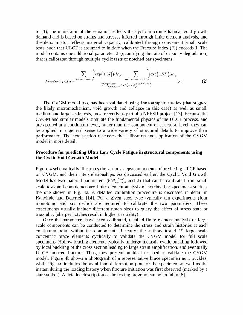
to (1), the numerator of the equation reflects the cyclic micromechanical void growth demand and is based on strains and stresses inferred through finite element analysis, and the denominator reflects material capacity, calibrated through convenient small scale tests, such that ULCF is assumed to initiate when the Fracture Index (FI) exceeds 1. The model contains one additional parameter λ (quantifying the rate of capacity degradation) that is calibrated through multiple cyclic tests of notched bar specimens.
( ) ( )2 2
1 1
exp 1.5 . exp 1.5 .
1exp( )
p ptensile cycles compressive cycles
critical accumulatedmonotonic p
T d T d
Fracture IndexVGI
ε ε
ε ε
ε ε
λε− −
−
= >−
∑ ∑∫ ∫ (2)
The CVGM model too, has been validated using fractographic studies (that suggest
the likely micromechanism, void growth and collapse in this case) as well as small, medium and large scale tests, most recently as part of a NEESR project [13]. Because the CVGM and similar models simulate the fundamental physics of the ULCF process, and are applied at a continuum level, rather than the component or structural level, they can be applied in a general sense to a wide variety of structural details to improve their performance. The next section discusses the calibration and application of the CVGM model in more detail. Procedure for predicting Ultra Low Cycle Fatigue in structural components using the Cyclic Void Growth Model Figure 4 schematically illustrates the various steps/components of predicting ULCF based on CVGM, and their inter-relationships. As discussed earlier, the Cyclic Void Growth Model has two material parameters ( critical
monotonicVGI and )λ that can be calibrated from small scale tests and complementary finite element analysis of notched bar specimens such as the one shown in Fig. 4a. A detailed calibration procedure is discussed in detail in Kanvinde and Deierlein [14]. For a given steel type typically ten experiments (four monotonic and six cyclic) are required to calibrate the two parameters. These experiments usually include different notch sizes to query the effect of stress state or triaxiality (sharper notches result in higher triaxiality).
Once the parameters have been calibrated, detailed finite element analysis of large scale components can be conducted to determine the stress and strain histories at each continuum point within the component. Recently, the authors tested 19 large scale concentric brace elements cyclically to validate the CVGM model for full scale specimens. Hollow bracing elements typically undergo inelastic cyclic buckling followed by local buckling of the cross section leading to large strain amplification, and eventually ULCF induced fracture. Thus, they present an ideal test-bed to validate the CVGM model. Figure 4b shows a photograph of a representative brace specimen as it buckles, while Fig. 4c includes the axial load deformation plot for the specimen, as well as the instant during the loading history when fracture initiation was first observed (marked by a star symbol). A detailed description of the testing program can be found in [8].

Figure 4d shows a FEM simulation (performed on ABAQUS [1]) of this specimen (the brace is a 10 foot long HSS 4X4X1/4 shape). The simulation considers all the relevant aspects of behavior, and features multiaxial plasticity with combined isotropic and kinematic hardening. The parameters for the plasticity model are inferred from the small scale coupon tests. To simulate the local buckling accurately, initial imperfections must be prescribed to perturb the analysis. Initial imperfections are inputted into the model by scaling the appropriate global and local buckling modes of the brace to measured imperfections of the experimental specimen. A simulation-based load deformation plot is overlaid on the experimental plot in Fig. 4c, and the agreement between the two is very good.
FIGURE 4 PREDICTION OF ULCF IN A CONCENTRIC BRACE USING THE CYCLIC VOID GROWTH MODEL
To predict the location and instant of ULCF initiation, the stress and strain histories
are determined from the FEM simulation over the entire plastic hinge region as the loading progresses, and the Fracture Index (FI) is determined as per (2) at each loading step. It is important to note that FI is determined at each continuum location in the FEM model, and is dependent on material parameters ( critical
monotonicVGI and )λ . Thus, the FI can be determined in a general sense for any component once the material properties have been calibrated using the small scale tests. ULCF is assumed to initiate at a given continuum location when the micromechanical cyclic void growth demand exceeds degraded void size capacity, or mathematically, FI at that location exceeds 1. Fig. 4e plots the FI at the
Brace geometry, boundary conditions
and loading information
Material notched bar tests
Material properties
,criticalmonotonicVGI λ Large scale FEM analysis
Using stress and strain histories to compute Fracture Index based on
CVGM
Large scale brace tests
Material coupon
extraction
Analytical prediction of failure
(a) (b) (c)
(d)(e)

critical location in the locally buckled cross-section profile (indicated by the arrow in Fig. 4d), versus the loading time step. The instant when FI exceeds 1 for the first time is recorded as the analytical prediction of ULCF initiation. This point is shown as circle on Fig. 4c. Comparing this point to the experimental fracture instant (shown as a circle in the figure) demonstrates the accuracy of the ULCF models. Furthermore, as is evident from Fig. 4c, the instant of ductile crack initiation predicted from the analysis is very close to that observed during the experiment. Moreover, the physical location of ULCF is predicted with exact precision by the CVGM model.
As noted from Fig. 4c, the CVGM model successfully predicts the point of ULCF initiation in the experiment. Similar agreement between experimental and analytical fracture is observed for all 19 specimens. Given that the test matrix included specimens with different cross section geometries, different steel materials and loading histories, the good agreement between experimental and CVGM predictions of fracture indicates that the CVGM does indeed capture fundamental physical processes and material properties that control fracture. Thus, once material properties are determined using small-scale tests, the CVGM can be applied in a general sense across a range of component geometries, materials and loading histories. AREAS FOR REFINEMENT OF THE MICROMECHANICS-BASED MODELING APPROACH While the CVGM and similar micromechanical models provide a fairly general and accurate framework for predicting earthquake induced fracture in steel structures, there are several issues that need to be addressed to successfully and routinely apply these models in structural simulations. Some of these issues concern the level of sophistication of the FEM simulation, while others are related to the accuracy of the micromechanics-based model itself. Some of these issues are now summarized. • Because the micromechanics-based models are applied at the continuum level, their
success is contingent on an accurate characterization of the local stress and strain histories at critical locations. Thus, sophisticated modeling of various physical phenomena that affect these stresses and strains is required. For example, the brace specimens described in this paper required simulation of global and local buckling, which in turn required a detailed definition of initial member imperfections. One can envision that in other situations, various mechanisms may become critical, e.g. gapping and contact in connections including fillet welds, or the loosening of bolts in bolted connections. In addition to this, multiaxial cyclic plasticity model typically need to be calibrated and used for accurate material constitutive response.
• In many situations such as welded connections (that include base and weld metal and heat affected zones) it is necessary to consider the spatial gradients and statistical variability in material properties and capacities that may affect the instant and location of ULCF initiation. The second phase of the NEESR project (referenced earlier), uses welded column base plate details as a test-bed and investigates some of these issues.
• While the model discussed in this paper addresses mainly ULCF initiation, often the fracture propagates in a ductile manner for a considerable duration of time before the component fractures completely. Thus, methods are required to integrate the initiation

models with analytical crack propagation capabilities to achieve more realistic estimates of performance.
• Another important issue to consider with regard to the micromechanics-based models is that they typically focus on a single mechanism for failure (e.g. microvoid growth and coalescence). However, depending on stress conditions and material properties, various other mechanisms may be possible, such as intragranular cleavage (Fig. 5a) or intergranular fracture (Fig 5b). In fact, in many cases fracture may initiate as ductile microvoid growth type fracture, and transition to brittle cleavage as the crack grows [3]. Thus, appropriate models need to be chosen for a given situation. For most ductile structural components, without sharp cracks or flaws, fracture typically initiates due to microvoid growth, and the CVGM may be appropriate for such situations.
FIGURE 5 OTHER MECHANISMS OF FRACTURE – (A) INTRAGRANULAR CLEAVAGE AND (B) INTERGRANULAR FRACTURE – ADAPTED FROM ANDERSON 1995 Thus, while the micromechanics-based models offer an attractive and physics-based approach to predicting ULCF, they also require more sophisticated modeling of many physical phenomena and knowledge of potential micromechanisms of failure. Moreover, for sharp crack type situations, where the stress gradients are high, these methods typically require characterizing stresses and strains with a high spatial resolution, often requiring significant computational resources. However, given the cost of experimentation, and the decreasing cost of computational technology, these approaches will likely become more widespread in the future. SUMMARY This paper reviews various methods to predict earthquake-induced fracture in steel structures, and presents the physics-based micromechanical approach as a general, accurate and viable approach. Earthquake-induced fracture in structures is an important limit state, often controlling the ductility of the structural system. Unlike high-cycle fatigue or low-cycle fatigue observed in bridges or mechanical components that are subjected to thousands or millions of cycles, earthquake-induced Ultra-Low Cycle Fatigue (ULCF) is characterized by a very small number (<10) of random, high
(a) (b)

amplitude cycles. However, fundamental approaches to predict ULCF in steel structures are not well developed.
Traditional models to characterize earthquake-induced fracture have relied on experimental or empirical approaches, or on adaptation of techniques originally developed for other problems (such as high-cycle fatigue). Consequently, predictions from these models cannot be generalized to components and situations beyond those that are experimentally tested. Moreover, these costly approaches do not provide insights into local effects that are responsible for fracture. More recently, Conventional Fracture Mechanics (CFM) methods have been used to assess the fracture susceptibility of structural components. While an improvement over experiment-based methods, the CFM methods are limited by assumptions of small-scale yielding and monotonic loading that are not typical to ductile details subjected to earthquake-type ULCF.
Physics-based models that simulate the fundamental micromechanics of the fracture-ULCF process are presented as an attractive alternative to traditional methods. These are fracture criteria based on continuum stress and strain quantities, and thus can be applied to a variety of structural details once the material properties are calibrated. The Cyclic Void Growth Model (CVGM), presented in this paper is one such model that simulates the micromechanical processes of cyclic void growth, collapse and damage to predict ULCF initiation. The application of the CVGM model requires the calibration of two material parameters. This is done through fairly economical small scale notched bar cyclic tests. A procedure for predicting ULCF initiation based on CVGM is outlined, and validation experiment results are presented which suggest that the CVGM simulates fundamental material behavior and can be applied in a general sense to a wide variety of structural components and configurations.
However, being highly dependent on the accurate characterization of local stress and strain histories, these micromechanical models require the simulation of other physical processes such as global and local buckling, contact, gapping etc. Also important are aspects such as the spatial gradients and statistical variability in material properties. Moreover, these models are typically focused on a single micromechanism, so multiple models (e.g. addressing void growth, cleavage) may need to operate simultaneously for an accurate simulation.
It is important to note that micromechanics-based earthquake-induced fracture prediction approaches are relatively recent, and need refinement to be widely accepted. However, given their fundamental appeal, flexibility and generality, coupled with the research community’s shift towards model-based simulation, they may be a viable alternative to experimental approaches in the future. ACKNOWLEDGEMENTS This research was supported by the National Science Foundation (NSF Grant CMS 0421492), the George E. Brown Jr. Network for Earthquake Engineering Simulation (NEES), and the Structural Steel Educational Council (SSEC). The advice and guidance of Helmut Krawinkler (Stanford University), Stephen Mahin (University of California at Berkeley), Charles Roeder (University of Washington) is greatly appreciated. In addition, the knowledgeable support of the UC Berkeley NEES lab personnel including Shakhzod Takhirov, Donald Patterson, Donald Clyde, David

MacLam, and Jose Robles was extremely important in the experimental aspect of this study. The authors also acknowledge support from the John A. Blume Earthquake Engineering Center at Stanford University and the University of California at Davis. REFERENCES [1] ABAQUS, Abaqus User Manual, 1998. [2] Anderson, T.L, Fracture Mechanics, 2nd Ed., CRC Press, Boca Raton, FL. 1995. [3] Beremin, F.M. “A local criterion for cleavage fracture of a nuclear pressure vessel steel” Metallurgical
Transactions A. Vol. 14, 1983, 2277–2287.
[4] Chi. W-M. “Prediction of steel connection failure using computational fracture mechanics,” Ph.D. Thesis, Stanford University, Stanford, CA. 2000.
[5] Chi. W-M, Kanvinde, A.M., and Deierlein, G.G. “Prediction of Ductile Fracture In Welded
Connections Using the SMCS Criterion,” Journal of Structural Engineering, ASCE, Vol. 132(2), 2006, 171-181.
[6] Coffin, L. F., Jr.,. "A Study of the Effects of Cyclic Thermal Stresses on a Ductile Metal," Trans.
ASME, Vol. 76, 1954, 931–950 [7] El-Tawil, S., Vidarsson, E., Mikesell, T., and Kunnath, K. “Inelastic behavior and design of steel panel
zones.” Journal of Structural Engineering, ASCE, Vol. 125(2). 1999. 183-193. [8] Fell, B.V., Kanvinde, A.M., Deierlein, G.G., Myers, A.T., and Fu, X “Buckling and fracture of
concentric braces under inelastic cyclic loading,” SteelTIPS, Technical Information and Product Service, Structural Steel Educational Council. 2006.
[9] FEMA (2000), “Recommended Design Criteria for New Steel Moment-Frame Buildings FEMA–
350,” Federal Emergency Management Agency, July 2000. [10] Hancock, J. W. and Mackenzie, A. C. “On the mechanics of ductile failure in high-strength steel
subjected to multi-axial stress-states,” Journal of Mechanics and Physics of Solids, Vol. 24(3), 1976, 147-169
[11] Hancock, J.W., and Brown, D.K.. “On the role of strain and stress state in ductile failure,” Journal of
the Mechanics and Physics of Solids, Vol. 31(1), 1983, 1-24. [12] Johnson, G.B., Cook, W.H.. “Fracture characteristics of three metals subjected to various strains, strain
rates, temperatures and pressures,” Engineering Fracture Mechanics, Vol. 21(1). 1985. 31-48. [13] Kanvinde, A.M., PI, Deierlein, G.G., co-PI “Large scale testing and micromechanical simulation of
ultra low cycle fatigue cracking in steel structures” NSF-NEESR award 0421492. [14] Kanvinde, A. M. and Deierlein, G.G. “Micromechanical Simulation of Earthquake Induced Fracture in
Steel Structures,” Technical Report 145, John A. Blume Earthquake Engineering Center, Stanford University, CA. 2004.
[15] Liu, Z., and Goel, S.C. “Cyclic Load Behavior of Concrete-Filled Tubular Braces.” Journal. of
Structural Engineering. ASCE, Vol. 114 (7), 1988, 1488-1506
[16] Okazaki, T., Engelhardt, M., Nakashima, M., and Suita, K. “Experimental Performance of Link to Column Connections in Eccentrically Braced Frames.” Journal of Structural Engineering, ASCE, Vol. 132(8), 2006, 1201-1211.
[17] Panontin, T. L. and Sheppard, S. D. “The relationship between constraint and ductile fracture initiation
as defined by micromechanical analyses,” Fracture Mechanics: 26th Volume. ASTM STP 1256. 1995. 54-85.
[18] Pineau, A. “Development of the Local Approach to Fracture over the last 25 years: Theory and
Application.” International Journal of Fracture, Vol. 138, 2005, 139-166. [19] Rice, J. R. and Tracey, D. M. “On the ductile enlargement of voids in triaxial stress fields,” Journal of
the Mechanics and Physics of Solids, Vol. 35. 1969. 201-217 [20] Stojadinovic, B., Goel, S., and Lee, K.H. “Development of post-Northridge steel moment
connections.” Proceedings of the 12th World Conference on Earthquake Engineering, New Zealand, paper 1269. 2000.
[21] Tatsuo, E., Koichi, M., Kiyohumi, T., Kakuichi, K., Masanori, M. “Damage evaluation of metals for
random of varying loading – three aspects of rain flow method.” Journal of the Institution of Water Engineers and Scientists, 1974. 371-380
[22] Tremblay, R., Archambault, M-H, Filiatrault, A. “Seismic performance of concentrically braced steel
frames made with rectangular hollow bracing members.” Journal of Structural Engineering, ASCE, Vol. 129(120). 2003. 1626-1636.
[23] Uang, C.M and Fan, C.C, “Cyclic Stability Criteria for Steel Moment Connections with Reduced
Beam Section,” Journal of Structural Engineering, ASCE, Vol. 127(9) 2001, 1021-1027. [24] Uriz, P., and Mahin, S., (2004). “Seismic Performance Assessment of Concentrically Braced Steel
Frames.” Proceedings of the 13th World Conference on Earthquake Engineering, Vancouver, Canada, 2004.