physics aspects of the dynamic ergodic divertor (ded) · physics aspects of the dynamic ergodic...
TRANSCRIPT
J. Plasma Fusion Res. SERIES, YoI.5 (2002'1 77-81
Physics Aspects of the Dynamic Ergodic Divertor (DED)
FINKEN KarI H.I, KOBAYASHI Masahirol'2, ABDULLAEV Sadrilla S.I and JAKUBoWSKI Marcin1,3llnstitut fiir Plasmaphysik, Forschungsryntrum Jiilich GmbH, EURATOM Association,
D-52425 Jiilich, Germany, Partner in the Trilateral Euregio Cluster2Depa,menI;::;7,r:;T";:;::::,,:::,h;ilif,?""xi,:,";n;*:"r",a,lapan
(Received: 1l December 2001 / Accepted:24 April 2002)
AbstractThe Dynamic Ergodic Divertor (DED) is presently being installed in the TEXTOR tokamak. It
consists of 16 helical coils wound helically around the torus at the high fietd side (HFS). Theperturbation currents in these coils generate predominantly islands of m=10...14 and n=4leading both torather closed ergodic and to open laminar structures. In the "laminar mode", the DED forms a helicaldivertor'. 3D modelling (2D finite element/l D finite volume) of the plasma transport in the laminar zonehas started. By the "dynamic" operation of the DED, the heat is deposited to a wide area and forces are
transferred from the currents in the DED-coils to the plasma edge.
Keywords:ergodization, 3D modelling, force transfer
1. lntroductionThe formation of an ergodic layer can be an
interesting means of destroying the good confinementproperties of closed flux surfaces at special locations.Such a location of interest is the boundary of theplasma: The power - with the exception of the radiatedfraction - leaves the plasma conductively orconvectively and passes through a relatively thinboundary layer. In order to spread the heat to a largerarea, the Dynarnic Ergodic Divertor (DED) tll has been
developed and is presently being installed in theTEXTOR tokamak. The DED will create an ergodicboundary layer of the plasma and thus it is expected toallow for wider power deposition pattern, for an
improved screening of impurities, and for an enhanced
particle removal by the pump limiter ALT-II. The
expression "d1'namic" refers to a rotating perturbation
magnetic field imposed by the DED coils. For therotation, different frequencies are foreseen: At fewHertz, the heating pattern of the divertor strike zone is
smeared out over the large area of the divertor targetplate; at frequencies up to 10 kHz, locked modes can be
unlocked, or a differential rotation in the plasma edge
can be imposed with hopefully favourable effects on the
confinement. It is estimated that the rotating DEDcurrent generates a torque at the plasma edge.
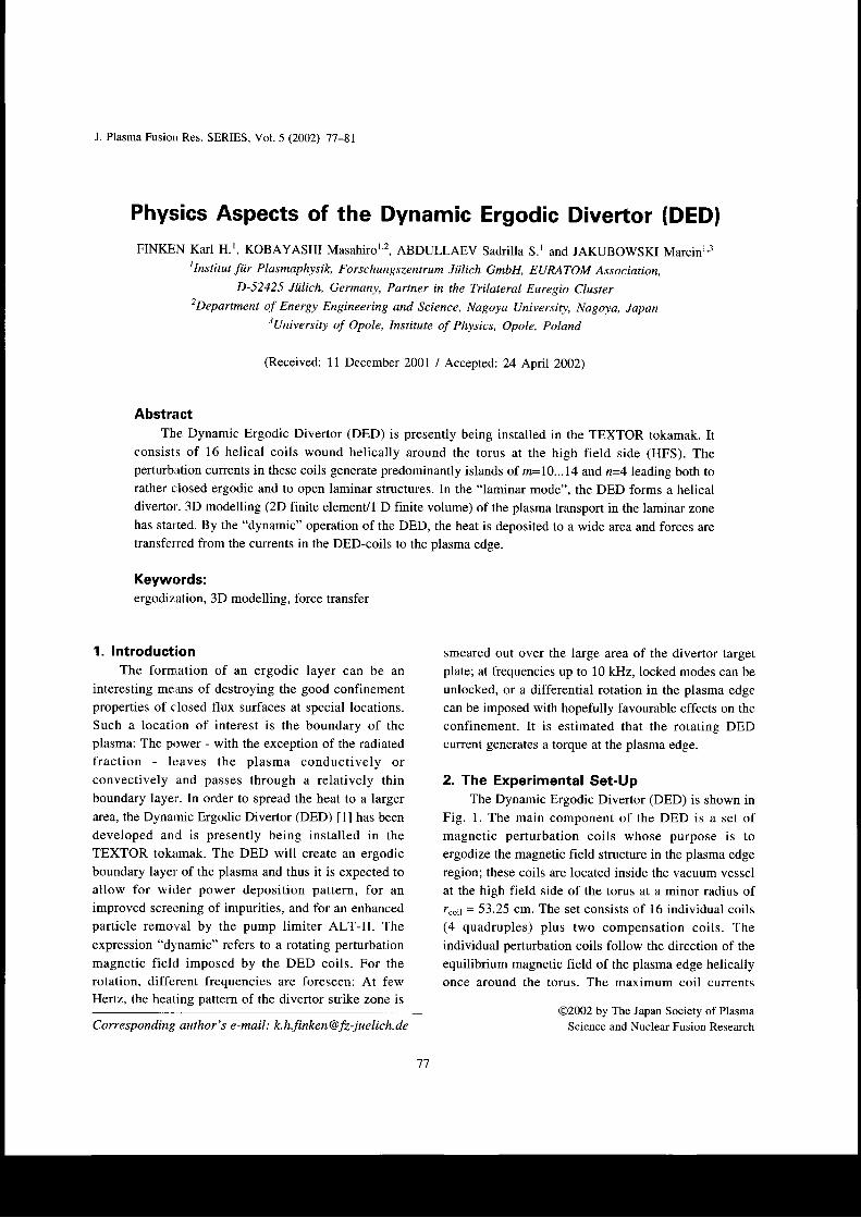
2. The Experimental Set-UpThe Dynamic Ergodic Divertor (DED) is shown in
Fig. 1. The main component of the DED is a set ofmagnetic perturbation coils whose purpose is toergodize the magnetic field structure in the plasma edge
region; these coils are located inside the vacuum vessel
at the high field side of the torus at a minor radius ofr"o1 = 53.25 cm. The set consists of 16 individual coils(4 quadruples) plus two compensation coils. Theindividual perturbation coils follow the direction of the
equilibrium magnetic field of the plasma edge helicallyonce around the torus. The maximum coil currents
@2002 by The Japan Society of Plasma
Science and Nuclear Fusion ResearchCorresponding author's e-mail: [email protected]
77
Finken K.H. e/ dl., Physics Aspects of the Dynamic Ergodic Divertor (DED))
50
48
e46o:44
42
40
38
Fig. 1 Schematic view of the DED-coils.
amounts to 15 kA.The main perturbation modes (m = 10...14, n = 4)
create chains of magnetic islands destroying the
resonant magnetic surfaces e = mln. Due to a strong
radial decay of the modes they do not disturb the plasma
core. The DED has the unique feature that the
perturbation field is not static as in most other devices
but that it has the option of rotation. To our knowledge
only the tokamak CSTN [2] at Nagoya University has
similar features and - at low perturbation current levels -
also the TEXT [3] tokamak. The DED can be operated
DC, around 50 Hz or at 7 frequencies in the band from IkHz to 10 kHz.
3. The Ergodic LayerThe perturbation coils impose structures with
different properties in the plasma boundary: The interiorclosed flux surfaces, q(r) 32, remain nearly undisturbed
and form for at least the well structured Kolmogorov,Arnold, Mozer (KAM)-surfaces [4]. Further towards the
boundary, islands develop and start to grow; finally,different islands overlap and form an ergodic sea [5-7]such that the magnetic surfaces are destroyed. The very
outermost magnetic field lines intersect the divertortarget plate. These field lines form the so called laminar
zone [8]; here the transport changes character fromdiffusive to convective with plasma streaming to the
plasma facing components as in the conventionalscrape-off layer.
Field line tracing and field line mapping [9,10] are
basic techniques for investigating the ergodic structure.
These techniques provide a picture of the areas withintact magnetic surfaces, of island structures and ofergodized regions. The resonant radius can be adjusted
0l2n
Q/2n
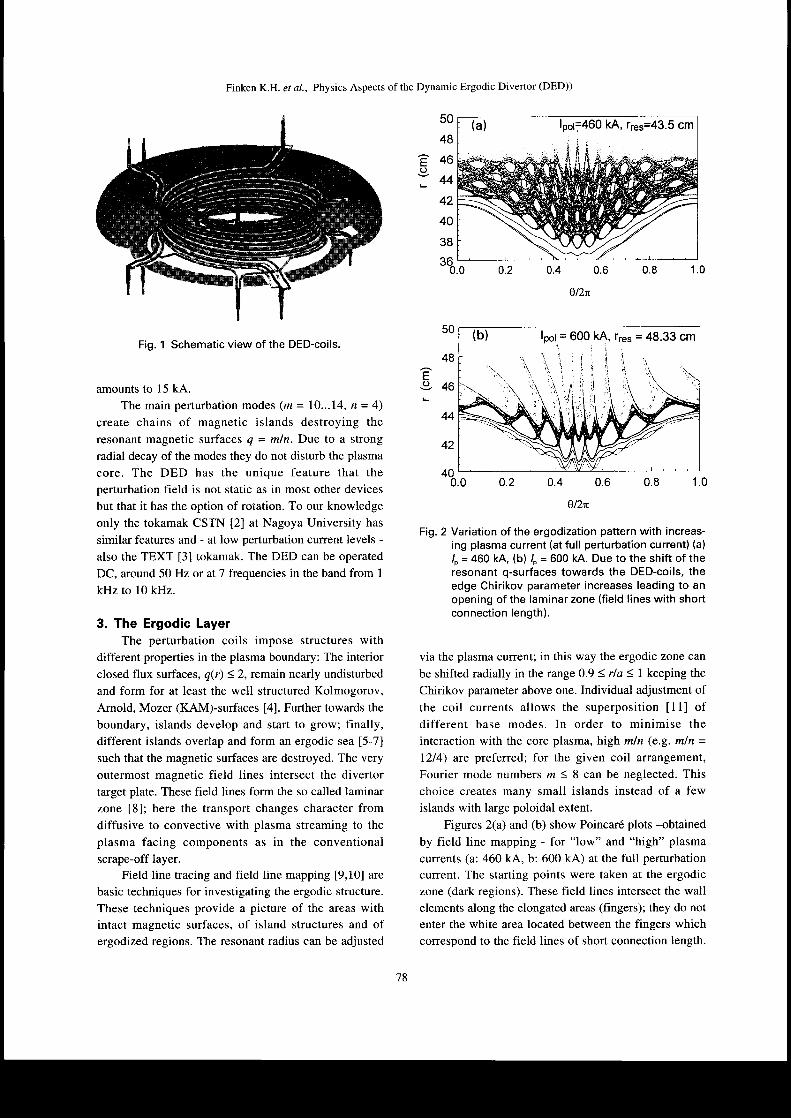
Fig. 2 Variation of the ergodization pattern with increas-ing plasma current (at full perturbation current) (a)
/" = 460 kA, (b) /" = 600 kA. Due to the shift of theresonant q-surfaces towards the DED-coils, theedge Chirikov parameter increases leading to anopening of the laminar zone (field lines with shortconnection length).
via the plasma current; in this way the ergodic zone can
be shifted radially in the range 0.9 3 rla < 1 keeping the
Chirikov parameter above one. Individual adjustment ofthe coil currents allows the superposition [11] ofdifferent base modes. In order to minimise the
interaction with the core plasma, high mln (e.g. mln =l2l4) are preferred; for the given coil arrangement,
Fourier mode numbers m 18 can be neglected. Thischoice creates many small islands instead of a fewislands with large poloidal extent.
Figures 2(a) and (b) show Poincar6 plots -obtainedby field line mapping - for "low" and "high" plasma
currents (a: 46O kA, b: 600 kA) at the full perturbation
current. The starting points were taken at the ergodic
zone (dark regions). These field lines intersect the wallelements along the elongated areas (fingers); they do not
enter the white area located between the fingers whichcorrespond to the field lines of short connection length.
50
48
E946
44
42
400.0 1.00.80.60.4o.2
78
Finken K.H. et al., Physics Aspects of the Dynamic Ergodic Divertor (DED))
With increasing plasma cuffent, the resonant surfaces
(2.25 < q < 3.75) move towards the outside, closer to the
DED coils. Highest ergodization levels with Chirikovparameters up to 6 are expected for plasma currentsaround 600 kA. The results of the field line mapping
seem at a first glance to be in conflict with thisexpectation: the radially widest ergodic zone is found at
the relatively krw plasma culrent of 460 kA while at 600
kA the properly ergodic zone is only a small band at aradius at about r = 44 cm. The outer zone of Fig. 2(b) is
nearly empty of Poincar6 intersection points and appffirs
white. The absence of the intersection points is a
consequence of the fact that the field line tracing isstopped after an intersection with a wall element. We
have stopped the tracing because the field linesrepresent also particles which would be neutralised and
can leave their field line. The "white" area contains the
field lines with a short connection length, i.e. a fewpoloidal turns. This area of short connection length iscalled the "laminar zone" |2,131and is discussed in the
next section. Because ofits short connection lengths, the
laminar zone is related to the scrape-off layer properties.
The attempt to increase the ergodic zone by increasing
the resonant perturbation at the edge evidently leads
more to an increase of the laminar layer than to a
widening of the ergodic zone.
4. Modelling of the Transport in the LaminarZone
Properties of the laminar zone are best represented
in a poloidal cut of the plasma edge at the low field side
(LFS) where areas are ordered according to the
connection lengths of the magnetic field lines between
two intersections with the walls. The poloidal width ofthe laminar plot corresponds to the m = 12 mode, the
dominant mode of the DED. By this choice all fieldlines intersect for at least once the reference frame; inaddition this area is opposite of the perturbation area
and it contains the stagnation areas for those field lines
which have an odd number of poloidal tums connecting
the walls.
For the case of a strong laminar zone, the areas
shortest connection length (one poloidal turn) is
relatively large, followed by successively smaller areas
of two and three poloidal tum areas. The structure of the
laminar zone are simple as compared to the one of the
ergodic zone, which has fractal properties. The channel
offield lines connecting the inner ergodic zone with the
wall is narrow (called fingers), for some conditions even
smaller than the Larmor radius. In our picture, the area
with field lines of short connection length region will be
most responsible for the final step of the transport ofenergy and particles to the wall. In this sense thelaminar zone is similar to the scrape-off layer of adivertor tokamak.
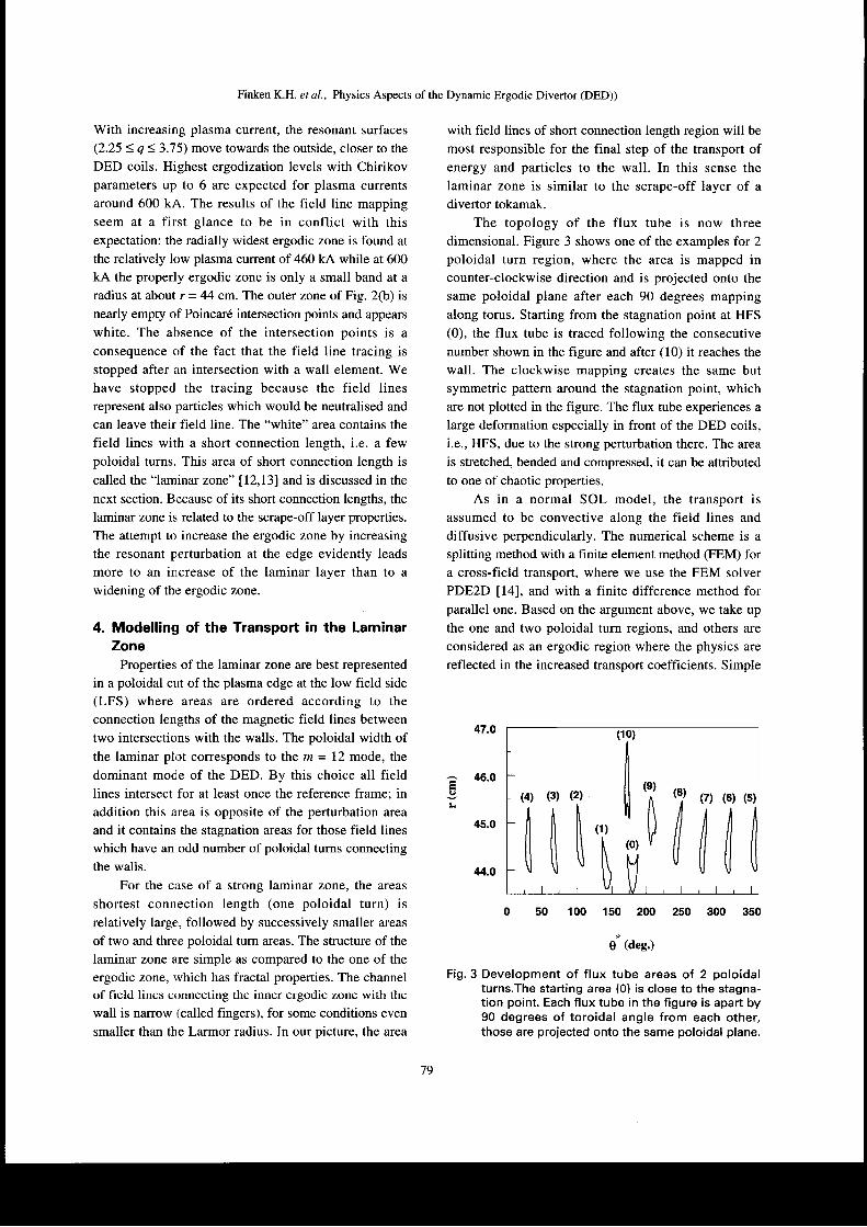
The topology of the flux tube is now threedimensional. Figure 3 shows one of the examples for 2
poloidal turn region, where the area is mapped incounter-clockwise direction and is projected onto the
same poloidal plane after each 90 degrees mappingalong torus. Starting from the stagnation point at HFS(0), the flux tube is traced following the consecutivenumber shown in the figure and after (10) it reaches the
wall. The clockwise mapping creates the same butsymmetric pattern around the stagnation point, whichare not plotted in the figure. The flux tube experiences a
large deformation especially in front of the DED coils,i.e., HFS, due to the strong perturbation there. The area
is stretched, bended and compressed, it can be attributed
to one of chaotic properties.
As in a normal SOL model, the transport is
assumed to be convective along the field lines and
diffusive perpendicularly. The numerical scheme is asplitting method with a finite element method (FEM) fora cross-field transport, where we use the FEM solver
PDE2D [4], and with a finite difference method forparallel one. Based on the argument above, we take up
the one and two poloidal turn regions, and others are
considered as an ergodic region where the physics are
reflected in the increased transport coefficients. Simple
44.0
0 50 100 150 200 250 300 350
e* (deg.)
Fig. 3 Development of flux tube areas of 2 poloidalturns.The starting area (0) is close to the stagna-tion point. Each flux tube in the figure is apart by90 degrees of toroidal angle from each other,those are projected onto the same poloidal plane.
a 46.0
45.0
(10)
il
It
tl
(0) il/,[,I,(4) (3) (2)
ilrIilil[\l\t\]
(1)
79
WFinken K.H. et al., Phy srcs Aspects of the Dynamic Ergodic Divertor (DED))
!
9-
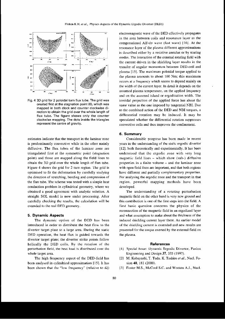
Fig. 4 3D grid for 2 poloidal turn flux tube. The grid wascreated first at the stagnation point (0), which wasmapped in both clock and counter clockwise di-rection to obtain the grid over the whole length offlux tube. The figure shows only the counterclockwise mapping. The dots inside the trianglesrepresent the centre of gravity.
estimates indicate that the transport in the laminar zone
is predominantly convective while in the other mainlydiffusive. The flux tubes of the laminar zone are
triangulated first at the symmetric point (stagnation
point) and those are mapped along the field lines toobtain the 3D grid over the whole length of flux tube.
Figure 4 shows the grid for 2 turn region. The grid isoptimised to fit the deformation by carefully studying
the direction of stretching, bending and compression ofthe flux tube. The scheme was tested with a simple heat
conduction problem in cylindrical geometry, where we
obtained a good agreement with analytic solution. Astraight SOL model is now under processing. Aftercarefully checking the results, the calculation will be
extended to the real DED geometry.
5. Dynamic AspectsThe dynamic option of the DED has been
introduced in order to distribute the heat flow to the
divertor target plate to a large area. During the static
DED operation, the heat flux is guided towards the
divertor target plate; the divertor strike points followhelically the DED coils. By the rotation of theperturbation field, the heat load is distributed over the
whole target area.
The high frequency aspect of the DED-field has
been analysed in cylindrical approximation [15]. It has
been shown that the "low frequency" (relative to (2,)
electromagnetic wave of the DED effectively propagates
in the area between coils and resonance layer as the
compressional Alfvdn wave (fast wave) [16]. At the
resonance layer of the plasma different approximations
is described either by a resistive annulus or by tearing
modes. The interaction of the extemal rotating field withthe current driven in the shielding layer results in the
transfer of angular momentum between DED-coil and
plasma [15]. The maximum poloidal torque applied to
the plasma amounts to about 100 Nm; this maximum
occurs at a frequency which seems to depend mainly on
the width of the current layer. In detail it depends on the
assumed plasma temperature, on the applied frequency
and on the assumed island or ergodization width. The
toroidal projection of the applied force has about the
same value as the one imposed by tangential NBL Due
to the combined action of the DED and NBI torques, a
differential rotation may be induced. It may be
speculated whether the differential rotation suppresses
convective cells and thus improves the confinement.
6. SummaryConsiderable progress has been made in recent
years in the understanding of the static ergodic divertor
[12], both theoretically and experimentally. It has been
understood that the ergodic zone with very longmagnetic field lines - which show (sub-) diffusiveproperties in a finite volume - and the laminar zone
with open field lines are important, and that both regions
have different and partially complementary properties.
For analysing the ergodic zone and the transport in that
region, powerful mapping methods have been
developed.
The understanding of a rotating perturbation
magnetic field on the other hand is very new ground and
this contribution is one of the first steps into the field. Afirst basic question concerns the physics of the
reconnection of the magnetic field in an ergodized layer
and what assumption to make about the thickness of the
induced shielding current layer there. An earlier model
of the shielding current is extended and new results are
presented for the torque exerted by the external field on
the plasma.
References[] Special Issue: Dynamic Ergodic Divertor, Fusion
Engineering and Design 37,335 (1997).
t2l M. Kobayashi, T. Tuda, K. Tashiro et a/., Nucl. Fu-
sion 40, 181 (2000).
[3] Foster M.S., McCool S.C. and Wooton A.J., Nucl.
80
Finken K.H. er al., Physics Aspects of the Dynamic Ergodic Divertor (DED))
Fusion 35,329 (1995).
[4] J.A. Lichtenberg and M.A. Lieberman, "Regular
and stochastic motion" rn Applied MathematicalSciences,38, Springer, New York, 1983.
[5] Evans, T.E. et c/., J. Nucl. Mater. 145-147,8I2(1987).
[6] Grosman, A. et al., J. Nucl. Mater. 196-198, 59/L992)..
[7] Takamura, S. et al.,Phys. Fluids 30, 144 (1987).
t8l Th. Eich, D. Reiser and K.H. Finken, Nucl. Fusion
40,1757 (2000).
t9l S.S. Abdullaev, K.H. Finken, A. Kaleck and K.H.Spatschek, Phys. Plasmas 5, 196 (1998).
[0] Abdullaev S.S., Finken K.H. and Spatschek K.H.,Physics of Plasmas 6,153 (1999).
[11] Finken K.H., Abdullaev S.S., Kaleck A. and WolfG.H., Nucl. Fusion 39,637 (1999).
[12] Ghendrih P., Grosman A. and Capes H., Plasma
Phys. Contr. Fusion 38, 1653 (1996).
[3] Finken K.H., Eich, T. and Kaleck A., Nucl. Fusion
38, s15 (1998).
| 4l hnp : //memb e rs. ao l. com./pde 2 d/[15]Finken K.H., Nucl. Fusion 30,7O7 (1999).
[16] Faulconer D.W. and Koch R., Fusion Engineering
and Design 37,399 (1997).
8l