physics 21 solutions
DESCRIPTION
problem solutionTRANSCRIPT

Physics 21Fall, 2011
Equation Sheet
speed of light in vacuo c 3.00 × 10⁸ m/sGravitational constant G 6.67 × 10⁻¹¹ N m2/kg2
Avogadro’s Number NA 6.02 × 10²³ mol−1
Boltzmann’s constant kB 1.38 × 10⁻²³ J/Kcharge on electron e 1.60 × 10⁻¹⁹ Cfree space permittivity ε0 8.85 × 10⁻¹² C2/(N m2)free space permeability µ0 4π × 10−7 T m/Agravitational acceleration g 9.807 m/s2
Planck’s constant h 6.626 × 10⁻³⁴ J sPlanck’s constant/(2π) h = h/2π 1.055 × 10⁻³⁴ J selectron rest mass me 9.11 × 10⁻³¹ kgproton rest mass mp 1.6726 × 10⁻²⁷ kgneutron rest mass mn 1.6749 × 10⁻²⁷ kgatomic mass unit u 1.6605 × 10⁻²⁷ kg1/(4πε0) k 8.99 × 10⁹ N m2/C2
F2 on1 =1
4πε0
q1q2(r1 − r2)
|r1 − r2|3F = qE
dE (at r) =1
4πε0
dQ (r − r′)
|r − r′|3E = −∇V
= −(
i∂V
∂x+ j
∂V
∂y+ k
∂V
∂z
)
Vf − Vi = − ∫ f
iE · dl
V =1
4πε0
Q
r; dV =
1
4πε0
dQ
|r − r′|uelec = 1
2ε0E
2, umag =1
2µ0B2
Work =∫
F · dl
Eline =1
2πε0
λ
r; Eplane =
σ
2ε0
E =Q
ε0A=
σ
ε0
for ‖ platecapacitor
Q=CV ; C =ε0KA
d=ε
A
d
Ucap = 12CV 2 = 1
2
Q2
C
Uind = 12LI2
V = IR R =ρL
A
P = IV P = I2R
R = mv⊥/(qB) circ. orbit
A × B =
∣∣∣∣∣∣i j k
Ax Ay Az
Bx By Bz
∣∣∣∣∣∣
ξi=Ci (series) or Ri (parallel):
1
ξeffective=
1
ξ1+
1
ξ2
ξi=Ci (parallel) or Ri (series):
ξeffective = ξ1 + ξ2
XR = R, XL = ωL, XC =1
ωCRC time constant = RC
LR time constant = L/R
Q(t) for RLC circuit
Q0 exp(−Rt/2L) cos ωt
ω2 =1
LC− R2
4L2
F=qv × B; dF=Idl × B
dB =µ0
4π
Idl × (r − r′)
|r − r′|3
long wire: B =µ0I
2πRcenter loop: B = µ0I/2R
I =dQ
dtI = −neAvd
Vs
Vp=
Ns
Np,
Is
Ip=
Np
Ns
χm =µ
µ0− 1
τ = µ × B µ = IA
solenoid B = µ0nI
solenoid L = µ0N2A/l
∮E · dA =
Q
ε0∮B · dA = 0
∮E · dl = − d
dt
∫B · dA
∮B · dl = µ0I + µ0ε0
d
dt
∫E · dA
sin(a ± b) = sin a cos b ± cos a sin b
sin(θ ± π2) = sin θ cos π
2± cos θ sin π
2
= ± cos θ
cos(a ± b) = cos a cos b ∓ sin a sin b
sin a + sin b = 2 cos(
a − b
2
)sin
(a + b
2
)
C = 2πr circumference of circleC = πd circumference of circleA = πr2 area of circleA = 4πr2 surface area of sphereV = 4
3πr3 volume of sphere
ax2 + bx + c = 0 ⇒x =
−b ±√b2 − 4ac
2a
∫du√
a2 + u2= ln
(u +
√a2 + u2
)∫
u du√a2 + u2
=√
a2 + u2
∫du
a2 + u2=
1
atan−1
(u
a
)∫
u du
a2 + u2= 1
2ln
(a2 + u2
)
∫du
(a2 + u2)3/2=
u
a2√
a2 + u2∫u du
(a2 + u2)3/2= − 1√
a2 + u2∫eau du =
1
aeau
∫ln u du = u ln u − u
∫un du =
1
n + 1un+1
∫du
a + bu=
1
bln(a + bu)
∫du
u= ln u
∫ 2π
0
cos2 θ dθ =
∫ 2π
0
sin2 θ dθ = π
v =√
T/ρ (T=tension)
v = (347.4 m/s)√
T/300
v = λf = ω/k
ω = 2πf k = 2π/λ
T = 1/f (T=period)
〈P 〉 = 12ρA2ω2v
∂ 2D
∂x2=
1
v2
∂ 2D
∂t2
S =1
µ0(E × B)
S = 12ε0cE
20 = 1
2
c
µ0B2
0
=E0B0
2µ0=
ErmsBrms
µ0
c = 1/√
ε0µ0
E × B ∝ v (plane wave)
∆x∆p >∼ h (h = h/2π)
λ = h/p (de Broglie)
− h2
2M
∂ 2ψ
∂x2= ih
∂ψ
∂t
KE = p2/(2M)
p = hk E = hω = hf
eiθ = cos θ + i sin θ
August 16, 2011

Physics 21Fall, 2011
Solution to HW-2
21-13 Three point charges are arranged on a line. Chargeq3 = +5.00 nC and is at the origin. Charge q2 = −3.00 nCand is at x2 = 4.50 cm. Charge q1 is at x1 = 1.00 cm. Whatis q1 (magnitude and sign) if the net force on q3 is zero?
x3=0 x1x2
q3 q1 q2
We can work this problem without using vectors by think-ing it through. Since q2 and q3 have opposite sign, the forceon q3 exerted by q2 is attractive (towards the right). If thetotal force on q3 is to be zero, the force exerted by q1 mustbe repulsive (toward the left). Thus q1 and q3 must have thesame sign, and q1 must be positive.
We can find the magnitude of q1 by equating the magni-tude of the forces on q3 exerted by q1 and q2:
14πε0
|q1q3|x2
1
=1
4πε0
|q2q3|x2
2
Cancelling like terms on both sides of the equation, we find
|q1| =(
x1
x2
)2
|q2| =(
1.0 cm4.5 cm
)2
(3 nC) = 0.148 nC.
We already concluded that q1 was positive.A more general way to solve this problem is to use the
vector expressions for the Coulomb force. We want
0 = F1 on 3 + F2 on 3,
where
0 =1
4πε0
q1q3(r3 − r1)|r3 − r1|3 +
14πε0
q2q3(r3 − r1)|r3 − r2|3 .
and we can evaluate the forces using the locations of thecharges. Because q1 is at the origin, r3 = 0. Also, r1 = x1 iand r2 = x2 i. Substituting for the vectors gives
0 =1
4πε0
[q1q3(0 − x1)i|0 − x1|3 +
q2q3(0 − x2)i|x2|3
]
=−q3
4πε0
[q1x1
|x1|2 +q2x2
|x2|2]i
Note that the terms in the denominators are lengths andmust be positive. The quantity in brackets must be zero, sowe obtain
q1 = −x2
x1
∣∣∣∣x1
x2
∣∣∣∣3
q2 = −4.51.0
∣∣∣∣1.04.5
∣∣∣∣2
(−3.0 nC) = 0.148 nC
This formula agrees with the previous result. Because wewere careful with the signs, the formula gives the correctanswer for any combination of signs of the three charges andfor the two vector components x1 and x2. (We took x3 = 0.)
21-15 Three point charges are located on the positive xaxis of a coordinate system. Charge q1 = 1.0 nC is 2.0 cmfrom the origin, charge q2 = −4.0 nC is 4.0 cm from theorigin and charge q3 = 6.0 nC is located at the origin. Whatis the net force (magnitude and direction) on charge q1 =1.0 nC exerted by the other two charges?
This problem is very similar to 21-13, and the same dia-gram applies. Here we need the sum F of F2 on 1 and F3 on 1,which is
F =1
4πε0
[q1q2(r1 − r2)|r1 − r2|3 +
q1q3(r1 − r3)|r1 − r3|3
],
where, as before, r3 = 0, r1 = x1 i, and r2 = x2 i. Then
F =1
4πε0q1
[q2(x1 − x2)i|x1 − x2|3 +
q3(x1 − x3)i|x1 − x3|3
]
=1
4πε0q1
[q2(−0.02m)(0.02m)3
+q3(0.02m)(0.02m)3
]i
Substituting the other numbers leads to
F = (9 × 10⁹)(1 nC)[−4 nC(−.02m)
(.02m)3+
6nC(.02m)(.02m)3
]i
= 2.25 × 10⁻⁴ N i
21-11 In an experiment in space, one proton is held fixedand another proton is released from rest a distance d away.What is the initial acceleration of the proton after it is re-leased?
From Physics 11 you know that F = ma, or a = F/m.So just find the electrostatic force on one proton due to theother proton, and then divide by the mass. We’ll drop thevector notation and just find the magnitude:
a =1
4πε0
e2
mpd2
=(9 × 10⁹ Nm2/C2
) (1.602 × 10⁻¹⁹ C
)2
(1.67 × 10⁻²⁶ kg) d2
When you substitute for d, don’t forget to convert to meters.For d = 3mm = 0.003m, the result is
a = 1.54 × 10⁴ m/s2.
August 31, 2011

21-46 Two particles having charges q1 = 0.600 nC andq2 = 5.00 nC are separated by a distance of d = 1.60 m. Atwhat point along the line connecting the two charges is thetotal electric field due to the two charges equal to zero?
0 x d
q1 q2
Since both charges are positive, it’s easy to keep track ofthe direction of the electric field. The field at x from q1
points to the right, and the one from q2 points to the left.These two fields must be equal in magnitude for their vectorsum to be zero. Therefore
14πε0
q1
x2=
14πε0
q2
(x − d)2
Cancelling the common factor of 1/(4πε0), we can rewritethe above equation as
(d − x)2
x2=
q2
q1⇒ d − x
x=
√q2
q1
Solving for x, we find
x =d
1 +√
q2/q1
Substituting the specific numbers given above leads to
x = 0.412m.
Note that instead of taking the square root and solvinga linear equation for x, one could also set up a quadraticequation. One must identify the correct root of the quadraticequation, but the result is the same.
YF 21-50 mod A point charge q1 = −4.00 nC is at thepoint x = 0.60 m, y = 0.80 m, and a second point chargeq2 = +6.00 nC is at the point x = 0.60 m, y = 0. (a,b)Calculate the x and y components of the net electric fieldat the origin due to these two point charges. (c,d) Calculatethe x and y components of the net electric field at the pointx = 0.90 m, y = 0.40 m due to these two point charges.
Use the vector expression given in class for the field E atr due to a charge Q at point r′. Apply this formula to getthe field at r due to Q1; apply it again to get the field at rdue to Q2, and then add the results (superposition).
E (at r) =1
4πε0
Q (r − r′)|r − r′|3
Remember, r = field point; r′ = charge point.
y
x
(0.6, 0.8)
(0.6, 0.0)
Q1 = -4.0 nC
Q2 = +6.0 nC
(0.9, 0.4)
(a,b) Find E at origin, r = 0i+0j. For Q1, r′ = 0.6i+0.8j, sor− r′ = −0.6i− 0.8j and |r − r′| = 1.0 m. For Q2, r′ = 0.6i,so r − r′ = −0.6i and |r − r′| = 0.6 m.
E =1
4πε0
[−4 nC(−.6 i − .8 j)m
(1.0 m)3+
6 nC(−.6 i)m(.6 m)3
]
=1
4πε0
[i(
2.413
− 3.6(.6)3
)+ j
(3.213
)]nCm2
=1
4πε0
[−14.3 i + 3.2 j
] nCm2
=(−128.3 i + 28.77 j
)N/C
(c,d) Find E at point r = 0.9 i+0.4 j. For Q1, r′ = 0.6i+0.8j,so r−r′ = 0.3 i−0.4 j and |r − r′| = 0.5 m. For Q2, r′ = 0.6i,so r − r′ = 0.3 i + 0.4 j, and |r − r′| = 0.5 m.
E =1
4πε0
[−4 nC(.3 i − .4 j)m
(0.5 m)3+
6 nC(.3 i + .4 j)m(0.5 m)3
]
=1
4πε0
[i(−1.2 + 1.8) + j(1.6 + 2.4)
0.125
]nCm2
=1
4πε0
[4.8 i + 32 j
] nCm2
=(43.2 i + 287.7 j
)N/C

Physics 21Fall, 2011
Solution to HW-3
21-96 Positive charge Q is uniformly distributed arounda semicircle of radius a. Find the electric field (magnitudeand direction) at the center of curvature P .
x
y
dθ
dQ = λds
= λadθ
We start with the equation from the equation sheet thatgives the field at the field point r in terms of a charge dQ atthe charge point r′:
dE(r) =1
4πǫ0
dQ (r − r′)
|r − r′|3
The field point r (where we want to know E) is at the origin,so r = 0, and the charge point (where dQ is located) is
r′ = a cos θi + a sin θj,
where θ is the angle above the x-axis, so
r − r′ = −a cos θi − a sin θj, and |r − r′| = a.
Since we want to add up all the contribution from all dQ,we must relate dQ to dθ so that we can integrate over theangle θ spanned by the semicircle. The arc length ds sweptout by an angle dθ is adθ, so the charge dQ on ds is
dQ = λds = λa dθ,
where λ is the linear charge density (charge per unit length):
λ =Q
πa.
With all these substitutions, the original equation becomes
dE =1
4πǫ0
( Qπaadθ)(−a cos θi − a sin θj)
a3
=−Q
4π2ǫ0a2(cos θi + sin θj)dθ.
We can find the total field at the origin by integrating:
E =
∫
dE =
∫ π
0
−Q
4π2ǫ0a2(cos θi + sin θj) dθ.
We will look at each component of the integral over θ sepa-rately. We see that
∫ π
0
cos θ dθ = 0 and
∫ π
0
sin θ dθ = 2,
so we get
E = − Q
4π2ǫ0a2(0i + 2j) = − Q
2π2ǫ0a2j.
From this result we see the E has a magnitude of
Q
2π2ǫ0a2
and points in the −y direction or downward. The x compo-nent of the field is zero, as one would expect from symmetry.
21-105 Three charges are placed as shown in the figure.The magnitude of q1 is 2.00 µC, but its sign and the value ofthe charge q2 are not known. Charge q3 is +4.00 µC, and thenet force F on q3 is entirely in the negative x-direction. a)Calculate the magnitude of q2. b) Determine the magnitudeof the net force F on q3.
(a) We first determine the sign of the charge q1. We can dothis by thinking about which direction the force will be infor the different combinations of signs for charges q1 and q2.Since there is no y-component of the force on q3 we knowthat q1 and q2 must have opposite signs. Since the force isdirected in the negative x-direction we can infer that q1 mustbe negative and q2 must be positive.To determine q2 we calculate the the total force F = F1 on 3+F2 on 3 on q3. Expressions for F1 on 3 and F2 on 3 follow fromthe general expression for F2 on 1 on the equation sheet:
F1 on 3 =1
4πǫ0
q3q1(r3 − r1)
|r3 − r1|3, F2 on 3
1
4πǫ0
q3q2(r3 − r2)
|r3 − r2|3.
We need the position vectors of each charge. Let q1 be atthe origin. Then the position vectors r1 and r2 of q1 and q2
are trivial. For r3, we notice that cos θ = 4/5 = x/4 wherex is the x-component of the position vector of q3. Alongwith this and Pythagorean’s theorem we can find both xand y-components of r3. The result is
r1 = 0, r2 = 5 cm i, r3 = 3.2 cm i + 2.4 cm j
Knowing these position vectors we can write F1 on 3 andF2 on 3, in terms of the unknown charge q2:
F1 on 3 = −36N i − 27N j
F2 on 3 = (−24 × 106 N/C) q2 i + (32 × 106 N/C) q2 j
Since the net force on q3 is in the negative x-direction, thesum of the y-components must be 0. From the sum of they-components we find that the charge q2 = +0.844µC. Thecharge is positive, as expected by the reasoning above.(b) Using q2, we can now determine the net force on q3
by adding the components together. We already know thatthere is no net y-component, so the net force has only an x-component, which is the sum of the x components of F1 on 3
and F2 on 3. The magnitude of the total force is the absolutevalue of its x component, |F| = 56.26 N.
September 10, 2011

21-87 A proton with the mass m is projected into a uni-form electric field that points vertically upward and has mag-nitude E. The initial velocity of the proton has a magnitudev0 and is directed at an angle α below the horizontal. (a)Find the maximum distance hmax that the proton descendsvertically below its initial elevation. You can ignore gravita-tional forces. (b) After what horizontal distance d does theproton return to its original elevation? (c) Find the numer-ical value of hmax if E = 520N/C, v0 = 5.00 × 10⁴ m/s, andα = 35.0. (d) Find the numerical value of d if E = 520N/C,v0 = 5.00 × 10⁴ m/s, and α = 35.0.
Because the proton is a charged particle (charge e), whenit enters a region of uniform electric field, it experiences aconstant force according to the relationship F = eE. Inprevious physics classes, you have studied how a constantforce influences the motion of an object. In particular, recallthat Newton’s Second Law tells us how force and accelerationare related through the equation F = ma. Combining thesetwo equations allows us to calculate the acceleration:
a =eE
m.
Since the electric field is uniform, the acceleration will beconstant, and the proton will follow a parabolic trajectory,as shown in the figure.
The acceleration of the proton will be in the same directionas the electric field. Thus, there is zero acceleration alongthe x direction. This leads to the same type of problemas that studied in projectile motion near the surface of theearth. The only difference is that the acceleration is upwardinstead of downward. The equations we need to use are:
x direction y directionx = x0 + vx0t y = y0 + vy0
t + 12at2
vx = vx0 = constant vy = vy0+ at
v2y = v2
y0 + 2a∆y
Before we go any further, we must resolve the intial velocityvector into x and y components:
v0 = vx0 i + vy0 j,
where
vx0 = v0 cos α and vy0 = −v0 sin α.
(a) When the proton reaches its maximum “height”, the ycomponent of the velocity reaches 0 (see v1 in the figure).Substituting into v2
y = v2y0 + 2a∆y yields 0 = v2
0 sin2 α +2ay1, where y1 is the position at maximum “height”. By thechoice of coordinate system, this will be a negative position.
However, “height” is a scalar quantity, so we can solve fory1 and take the absolute value. We get an answer of
hmax =mv2
0 sin2 α
2eE.
(b) In order to calculate x2, the position when the protoncomes back up to its original height, we need to find thetime it takes to get there, t2. Because of the symmetry ofthe motion, t2 is just twice the time t1 needed to reach the“peak”. Using vy = vy0 + at, we substitute in vy = 0 at t1,use our expression for vy0, and solve for t1. Doubling thisresult gives us
t2 =2v0 sin α
a.
Substitute this expression into x = x0 + vx0t, use our ex-pression for a, and set x0 = 0 to get
x2 =2mv2
0 sinα cos α
eE.
This expression is also the answer for d, the distance travelledin the x direction, since d = x2 − x0 = x2 − 0.(c) and (d) Substituting in the given values, along with thefundamental constants e = 1.602×10⁻¹⁹ C and m = 1.673×10⁻²⁷ kg (see the equation sheet), yields
hmax = 8.26 × 10⁻³ m and d = 4.72 × 10⁻² m.
21-99 Two 1.20m nonconducting wires meet at a rightangle. One segment carries 2.00µC of charge distributeduniformly along its length, and the other carries −2.00µCdistributed uniformly along it, as shown in the figure. Find(a) the magnitude and (b) the direction of the electric fieldthese wires produce at point P , which is 60.0 cm from eachwire. If an electron is released at P , what is (c) the magni-tude and (d) the direction of the net force that these wiresexert on it?
(a) In class we worked out the vector electric field due to afinite line of charge at a field point located directly outwardfrom the midpoint of the line. The magnitude of the field is
E =1
2πǫ0
λ
d
a√d2 + a2
,
where d is the distance of the point from the line of charge,and a is half the length of the line. In this exercise, the twowires have the same length, the same magnitude of charge,

and are the same distance from the point P . Thus, we canadapt the formula above to the charge and spatial orientationof each wire by putting in the correct direction for each field.Recalling that λ = Q/L and a = L/2, we find
E =1
4πǫ0
Q
d
1√
d2 + (L/2)2
= (9 × 10⁹ Nm2/C2)2 × 10−6 C
0.6m
1√
(0.6m)2 + (0.6m)2
= 35355N/C.
The field E− due to the negatively charged wire is directedto the left, while the field E+ due to the positively chargedwire is straight down. We can use superposition to find thenet electric field
Enet = E− + E+ = −35355N/C i − 35355N/C j
Enet =√
E2−
+ E2+ = 5.00 × 10⁴ N/C
(b) Since the field vectors are perpendicular and of equalmagnitude, the net electric field will be 45 from either vec-tor, and 135 counterclockwise from the +y axis.(c) The force acting on a charge q is F = qE, so at P themagnitude of the force on the electron is
Fnet = eEnet = (1.60 × 10⁻¹⁹ C)(5.00 × 10⁴ N/C)
= 8.00 × 10⁻¹⁵ N.
(d) Since the electron has a negative charge, the force willbe directed opposite (180) from the electric field. Counter-clockwise from the +y axis, θ = 315.
21-104 A thin disk with a circular hole at its center,called an annulus, has inner radius R1 and outer radiusR2. The disk has a uniform positive surface charge den-sity σ on its surface. (a) Determine the total electric chargeon the annulus. (b) The annulus lies in the yz -plane,with its center at the origin. For an arbitrary point onthe x -axis (the axis of the annulus), find the magnitudeof the electric field E. Consider points above the annu-lus in the figure. (c) Find the direction of the electricfield E. Consider points above the annulus in the figure.
(a) Given a uniform positive surface charge density σ, thetotal electric charge on any surface is σA, where A is the
surface area. For an annulus, A = πR22 − πR2
1. MasteringPhysics is expecting a symbolic expression, so simply enter
σπ(
R22 − R2
1
)
(b) This problem is similar to Example 21.12 in the textbook.Our target is the electric field along a symmetry axis of acontinuous charge distribution. We can represent the chargedistribution as a collection of concentric rings of charge dQ.From lecture, we know the field of a single ring on its axisof symmetry, so all we have to do is add the contributionsof the rings. For a single ring,
Ering = i1
4πǫ0
Qx
(x2 + a2)3/2
where Q is the total charge on the ring, x is the distancealong the axis from the ring to the point at which we arefinding the field, and a is the radius of the ring. We will nowassume an infinitesimally thin ring, with charge dQ on it, ofradius r′, and thickness dr′. It will have a contribution tothe electric field
dE = i1
4πǫ0
dQx
(x2 + r′2)3/2
Before we can integrate this, we need to come up with anexpression that tells us how much charge is on our infinites-imally thin ring. We will approximate the area of the ringas circumference × thickness (this approximation works be-cause the ring is infinitesimally thin). So, dQ = σdA =σ2πr′dr′. We now have
dE = iσx
2ǫ0
r′dr′
(x2 + r′2)3/2
To get the net electric field, we integrate this expression fromr′ = R1 to r′ = R2.
E = iσx
2ǫ0
∫ R2
R1
r′dr′
(x2 + r′2)3/2
= iσx
2ǫ0
[
− 1√x2 + r′2
]R2
R1
= iσ
2ǫ0
1√
1 + (R1/x)2− 1
√
1 + (R2/x)2
Note that the integral used here is on the table of integralson the equation sheet. Mastering Physics is only asking forthe magnitude of the electric field here, so enter
σ
2ǫ0
1√
1 + (R1/x)2− 1
√
1 + (R2/x)2
(c) Here we select the direction of the electric field that wasfound in part (b), the positive x -direction.

Physics 21Fall, 2011
Solution to HW-4
22-7 The electric field due to an infinite line of charge isperpendicular to the line and has magnitude E = λ/2πε0r.Consider an imaginary cylinder with a radius of r = 0.200 mand length l = 0.465 m that has an infinite line of positivecharge running along its axis. The charge per unit lengthon the line is λ = 7.15µC/m. (a) What is the electric fluxthrough the cylinder due to this infinite line of charge? (b)What is the flux through the cylinder if its radius is increasedto r = 0.515 m? c) What is the flux through the cylinder ifits length is increased to l = 0.760 m?
(a) Because the electric field lines are perpendicular to theline of charge, they will also be perpendicular to the surfaceof the curved or “barrel” part of the cylinder, and parallelto the ends of the cylinder. Because the line of charge isconcentric with the cylinder, the field strength will also beconstant along the barrel part of the cylinder. Then theelectric flux can just be calculated by:
Φ = EAbarrel =λ
2πε0r2πrl = 375, 700 Nm2/C
Note that the r’s cancel; the flux is independent of the ra-dius of the cylinder. We can also use Gauss’ law to do thecalculation and obtain the same expression.
Φ =Qenc
ε0=
λl
ε0= 375, 700Nm2/C
(b) We already found in (a) that the flux is independent ofr; Gauss’ law also tells us that the flux through the cylinderonly depends on the charge enclosed. Because increasingthe radius does not change how much charge is enclosed, theanswer for part (b) should be the same as the answer forpart (a).
Φ = 375, 700 Nm2/C
(c) If the length of the cylinder is increased, the new fluxmust be calculated because now more charge on the line isenclosed.
Φ =Qenclosed
ε0=
λl
ε0= 614, 000Nm2/C
22-10 A point charge q1 = 4.00 nC is located on the x-axisat x = 2.00 m, and a second point charge q2 = −6.00 nCis on the y-axis at y = 1.00 m. What is the total electricflux due to these two point charges through a spherical sur-face centered at the origin and with radius (a) 0.500 m, (b)1.50 m, (c) 2.50 m?
q1
q2
Sa
Sb
Sc
The problem asks for total electric flux through a surface.Gauss’s Law helps here. The Equation Sheet gives Gauss’sLaw in the form:∮
E · dA =Q
ε0,
where the left hand side is the total electric flux ΦE througha surface S, and Q is the charge enclosed by S.(a) Surface Sa, whose radius is 0.500 m, encloses no charge.The total electric flux is zero (in any units).(b) Surface Sb encloses q2 but not q1, so Q = q2:
ΦE =q2
ε0=
−6.00 × 10⁻⁹ C8.85 × 10−12 C2Nm−2
= −678NC−1m2.
Note the units: NC−1 is electric field and m2 is area.(c) Surface Sc encloses both charges, so Q = q1 + q2:
ΦE =q1 + q2
ε0=
4.00 × 10⁻⁹ − 6.00 × 10⁻⁹
8.85 × 10−12
= −226NC−1m2.
September 12, 2011

22-20 The electric field 0.400m from a very long uniformline of charge is 840 N/C. How much charge is contatined ina 2.00-cm section of the line?
The equation for the electric field of an infinite wire is
E =1
2πε0
λ
r,
where r is the perpendicular distance to the wire, and λ ischarge per unit length. Solving for λ gives
λ = 2πε0rE
= 2π × 8.8541 × 10−12 × 0.4 × 840 = 1.86 × 10⁻⁸ Cm
If we muliply λ (in C/m) by the length (in m) we get charge:
λ × 0.02 = 3.74 × 10⁻¹⁰C
22-26 A conductor with an inner cavity, like that shownbelow, carries a total charge of Qcond = +4.80 nC. An addi-tional charge within the cavity, insulated from the conductor,is q = −6.20 nC. (a) How much charge is on the inner sur-face of the conductor? (b) How much charge is on the outersurface of the conductor?
(a) The Gaussian surface G shown includes the inner surfaceof the conductor. The electric field must be zero inside theconductor, making
∫G
E ·dA = 0, and thus the total electriccharge Qencl enclosed by G must be zero. The charges con-tained within the surface are the charge in the cavity q andthe charge on the conductor’s inner surface qinner, so
Qencl = 0 = qinner + q ⇒ qinner = −q = 6.20 nC.
(b) The total charge on the conductor Qcond is the sum ofthe charge on the inner surface qinner and the charge on theouter surface qouter. Hence
Qcond = 4.8 nC = qinner + qouter
qouter = 4.8 nC − qinner = 4.8 nC − 6.20 nC = −1.4 nC
22-24 A point charge of −2.11 µC is located in the centerof a spherical cavity of radius rcav = 6.50 cm inside an in-sulating spherical charged solid. The charge density in thesolid is ρ = 7.36× 10⁻⁴ C/m3. Calculate (a) the magnitudeand (b) the direction of the electric field inside the solid ata distance r = 9.48 cm from the center of the cavity.
(a) To find the electric field we can use Gauss’ Law,∮
S
E · dA =Qencl
ε0,
where we choose the Gaussian surface S to be a sphere ofradius r = 9.48 cm centered at the point charge. At everypoint on S the vector dA and E are perpendicular to S andare therefore parallel (or antiparallel – we’ll provisionallyassume the former). By symmetry, the electric field has thesame magnitude E everywhere on the surface, so we canevaluate the surface integral in terms of the unknown E,∮
S
E · dA =∮
S
E dA = 4πr2E =Qencl
ε0.
All that remains is to determine the charge enclosed by theGaussian surface, which consists of the point charge qpoint
and the charge Qinsul on the insulator, which we can calcu-late as ρV . (Note that the charge on an insulator can beevenly distributed throughout its volume with density ρ.)The volume V of the insulator inside S is the volume of Sless the volume of the cavity,
V =43πr3 − 4
3πr3
cav =43π(r3 − r3
cav)
=43π
[(.0948 m)3 − (.0650 m)3
]= .00242 m3.
Thus the total charge enclosed is given by
Qencl = qpoint + Qinsul = qpoint + ρVencl
= − 2.11×10⁻⁶ C+(.000736 C/m3)(.00242 m3)= − 3.3 × 10⁻⁷ C.
Now we can use the relation between E and Qencl:
E =Qencl
4πr2ε0
=−3.3 × 10⁻⁷ C
4π(9.48 × 10⁻² m)2(8.854 × 10⁻¹² C2/(Nm2))= − 3.3 × 10⁻⁵ N/C.
(b) Since the magnitude E must be positive, the minus signwe obtained for E above tells us that E and dA must beantiparallel, that is, E points into the surface.

Physics 21Fall, 2011
Solution to HW-5
22-4 A cube has sides of length L = 0.330m. It is placedwith one corner at the origin as shown in the figure. Theelectric field is not uniform but is given by
E = [−4.41N/(Cm)] x i + [3.29N/(Cm] z k.
(a) Find the electric flux through each of the six cube facesS1, S2, S3, S4, S5, S6. (b) Find the total electric charge insidethe cube.
(a) The electric flux is defined as Φ =∫
E · dA. BecausedA is always perpendicular to the surface, we only need thecomponent of the field that is normal to the surface of in-terest. (The dot product of dA with the parallel componentof the field will be zero.) For each of the six surfaces, it willwork out that the component normal to the surface is con-stant, so the surface integral will just be the constant valueof the normal component times the surface area L2.
For surface S1, there is no component of the electric fieldnormal to the surface (in the y direction j), so the electricflux Φ1 = 0.
For surface S2, the component of the electric field normalto the surface is in the +z direction, so take only the k
component of E. The integral over the surface is
∫ L
0
∫ L
0
3.29z dx dy = 3.29zL2.
To evaluate the electric field at the surface we set z = L,and then the flux is
Φ2 = 3.29L3 = 0.118Nm2/C
Surface S3 is similar to S1; there is no electric field compo-nent in the normal direction j, so the flux Φ3 = 0.
For surface S4, the normal direction is in the −z direction,so we need to take the negative of the k component. Theflux is that component integrated over the surface.
Φ4 = −
∫ L
0
∫ L
0
3.29z dx dy = −3.29zL2
But evaluating the electric field at z = 0 results in Φ4 = 0.
For surface S5, the normal direction is in the +x direction,so we integrate the i component over the surface.
Φ5 = −
∫ L
0
∫ L
0
4.41x dy dz = −4.41xL2
Evaluating this at x = L, gives the flux:
Φ5 = −4.41L3 = 0.158Nm2/C.
Surface S6 is similar, but the surface is located at x = 0 sothe flux evaluates to Φ6 = 0.(b) To find the total electric charge inside the cube, we canapply Gauss’ Law, which tells us that the total flux throughthis cube is equal to the charge enclosed, divided by ǫ0.
Φ1 + Φ2 + Φ3 + Φ4 + Φ5 + Φ6 =Qencl
ǫ0
Solving for Qencl and substituting the numbers gives
Qencl = (0 + 0.118 + 0 + 0 − 0.158 + 0)ǫ0
= −3.54 · 10−13 C.
22-26 A conductor with an inner cavity, like that shownbelow, carries a total charge of qtot = +5.80 nC. The chargewithin the cavity, insulated from the conductor, is qcenter =−7.10 nC. (a) How much charge is on the inner surface ofthe conductor? (b) How much charge is on the outer surfaceof the conductor?
Gaussian
Surface
qtot = +5.80 nCqouter
qinner
qcenter
-
-7.10 nC
(a) The insulated point in the center of the cavity will in-duce an opposite charge on the inner surface of the conduc-tor. The induced charge will have the same magnitude asthe center charge, qinner = +7.10 nC. We can prove this byplacing a Gaussian surface within the conductor that en-compasses the entire cavity and point charge. Inside theconductor E = 0, and therefor Qencl = qcenter + qinner = 0.(b) The total charge qtot on the conductor is a constant anddoes not change, but we must find how it is divided betweenthe inner and the outer surface.
qtot = qinner + qouter =⇒ qouter = qtot − qinner
qouter = 5.80 nC − 7.10 nC = −1.30 nC
September 15, 2011

23-8 Three equal 1.20µC point charges are placed at thecorners of an equilateral triangle whose sides are 0.500 mlong. What is the potential energy of the system? (Take aszero the potential energy of the three charges when they areinfinitely far apart.)
The total potential energy is obtained by summing up thepotential energy of interaction between each pair of charges(superposition). If we label the three charges 1, 2, and 3then
U = U12 + U13 + U23 =1
4πǫ0(q1q2
r12+
q1q3
r13+
q2q3
r23)
Since all three charges are identical and the separation ofany pair is the same, then
U =1
4πǫ0
3q2
r= (9 × 10⁹)
3(1.2 × 10⁻⁶ µC)2
0.500m= 0.078 J
23-5 A small metal sphere, carrying a net charge of q1 =−2.90 µC, is held in a stationary position by insulating sup-ports. A second small metal sphere, with a net charge ofq2 = −7.80 µC and mass 1.80 g, is projected toward q1.When the two spheres are ri = 0.800 m apart, q2 is movingtoward q1 with speed vi = 22.0 m/s. Assume that the twospheres can be treated as point charges. You can ignore theforce of gravity. (a) What is the speed of q2 when the spheresare rf = 0.430 m apart? (b) How close does q2 get to q1?
For this problem we will use the conservation of energy. Wefirst notice that the two charges are both negative, so theCoulomb force is repulsive. Particle 2 must therefore startwith positive kinetic energy KE, and as it approaches particle1, KE will diminish and the potential energy U will increaseby the same amount. We know
KE = 12mv2 and U =
1
4πǫ0
q1q2
|r1 − r2|,
where |r1 − r2| is the distance between the charges. We canevaluate the total energy Etot by substituting the given ini-tial values ri and vi:
Etot = 12mv2
i +1
4πǫ0
q1q2
ri
= 0.689841 J.
Since energy is conserved, Etot has the same value at anyother value of rf :
Etot = 12mv2
f +1
4πǫ0
q1q2
rf
.
By equating the two expressions for Etot, we see
12mv2
f +1
4πǫ0
q1q2
rf
= 0.689841 J. (1)
For part (a) we are given rf , and we need to solve Eq. (1)for vf . The result is
vf = 15.5m/s.
For part (b), we know that when q2 is closest to q1, the KEreaches its minimum value of zero, so we must set vf = 0 inEq. (1) and solve for rf . The result is
rf = 0.295m.
23-79 Electric charge is distributed uniformly along a thinrod of length a, with total charge Q. Take the potential tobe zero at infinity. (a) Find the potential at the point P ,a distance x to the right of the rod. (b) Find the potentialat the point R, a distance y above the right-hand end ofthe rod. (c) In part a, what does your result reduce to as xbecomes much larger than a? (d) In part b, what does yourresult reduce to as y becomes much larger than a?
We will express the potential dV at points P and R fromcharge dQ at the charge point r′ = x′ i, and then we integrateover the length of the charged rod (from x′ = −a to x′ = 0).The general formula is
dV =1
4πǫ0
dQ
|r − r′|.
The charge dQ can be related to the length dx′ using thelinear charge density:
dQ = λdx′ =Q
adx′.
(a) For point P , r = x i and r − r′ = (x − x′) i. Hence
dV =1
4πǫ0
Q
a
dx′
(x − x′)
V =
∫ 0
−a
dV =1
4πǫ0
Q
a
∫ 0
−a
dx′
x − x′=
1
4πǫ0
Q
aln
x + a
x
(b) For point R, r = y j and r − r′ = −x′ i + y j. Hence
dV =1
4πǫ0
Q
a
dx′
√
(−x′)2 + y2
V =1
4πǫ0
Q
a
∫ 0
−a
dx′
√
(x′)2 + y2=
Q
4πǫ0aln
y√
a2 + y2 − a
Another expression for the argument of the log follows from
y√
a2 + y2 − a=
√
a2 + y2 + a
y
(c,d) For x or y large compared to a, we can consider thewhole charge Q on the line to be a point charge at the ori-gin. The potential is then 1/(4πǫ) times Q/x for c or timesQ/y for d. Mathematically the result follows if we use theapproximation ln(1 + δ) ≈ δ for δ ≪ 1. The key steps are
lnx + a
x= ln(1 +
a
x) ≈
a
x
ln
√
a2 + y2 + a
y≈ ln
√
y2 + a
y≈ ln
(
1 +a
y
)
≈a
y.
Physics 21Fall, 2011
Solution to HW-6
23-9 A point charge q1 = 4.10 nC is placed at the origin,and a second point charge q2 = −2.9 nC is placed on thex-axis at x = +21.0 cm. A third point charge q3 = 2.1 nCis to be placed on the x-axis between q1 and q2. (Take aszero the potential energy of the three charges when they areinfinitely far apart.) a) What is the potential energy of thesystem of the three charges if q3 is placed at x = +11.0 cm?b) Where should q3 be placed to make the potential energyof the system equal to zero?
(a) The general formula for the potential energy between anytwo point charges labeled 1 and 2 is
U12 =1
4πǫ0
q1q2
|r1 − r2|,
where |r1 − r2| is the distance between the two charges. Tofind the total potential energy of several charges, we mustfind the potential energy due to each pair of point charges.So the total potential energy here is
Utotal = U12 + U13 + U23
=1
4πǫ0
(
q1q2
|0 − .21m| +q1q3
|0 − .11m| +q2q3
|.21m − .11m|
)
= −3.53 × 10⁻⁷ J
(b) We can say that q3 is placed at some point x betweenthe other two charges and determine which value of x givesthe system a total potential energy of zero. Incorporatingthis into the expression for the total potential energy gives:
Utotal =1
4πǫ0
(
q1q2
.21m+
q1q3
x+
q2q3
(.21m − x)
)
= 0
We can save ourselves some trouble by eliminating severaloverall factors that won’t affect the solution x. Since all theterms have exactly the same units, we can drop the conver-sion factors to SI units and write distances in cm and chargesin nC. The result is
(4.1)(−2.9)
21+
(4.1)(2.1)
x+
(−2.9)(2.1)
(21 − x)= 0
Multiply through by x(21 − x) to get a quadratic equation:
0.5662x2 − 26.59x + 180.81 = 0
Using the quadratic formula we find x = 38.72 or 8.25. Re-member that these values are in centimeters. Since the firstsolution is not between the two other point charges, we canignore it. So q3 must be placed in between the two chargesat x = 8.25 cm to give the system a total potential energyof zero.
23-31 (a) An electron is to be accelerated from a velocityof 2.50 × 10⁶ m/s to a velocity of 8.00 × 10⁶ m/s. Throughwhat potential difference must the electron pass to accom-plish this? (b) Through what potential difference must theelectron pass if it is to be slowed from 8.00 × 10⁶ m/s to ahalt?
This problem is a conservation of energy problem. The onlyforms of energy involved are electrical potential energy (U)and kinetic energy (K). Note that “potential difference”means the “change in voltage” (V2−V1) from the initial valueV1 to the final value V2, and that the relationship U = qVis not on your equation sheet.
(a)
K1 + U1 = K2 + U2
1
2mv2
1 + qV1 = 1
2mv2
2 + qV2
q(V2 − V1) = − 1
2m(v2
2 − v21)
The final equation shows that the change in potential energyis the negative of the change in kinetic energy, as expected.Dividing by the charge gives
V2 − V1 = −m
2q(v2
2 − v21).
Using the velocities given and remembering that q = −e foran electron gives us the answer
V2 − V1 = 164V.
Think carefully about the sign. A positively charged particlewould slow down when the potential goes up (like a massgoing uphill), but an electron behaves in the opposite way.
(b) With the same equation we found for part (a), we canrecalculate for the new velocities that
V2 − V1 = −182V.
In this case, the particle slows down, so a positively chargedparticle would go through a positive change in potential, butagain the electron does the opposite.Note that on Mastering Physics, the question asks for thevalue of V1 −V2, not V2 −V1. So, the numerical answers youshould give are −164V and 182V.
September 16, 2011
23-36 A very long insulating cylinder of charge of radius3.00 cm carries a uniform linear density of 15.0 nC/m. If youput one probe of a voltmeter at the surface, how far from thesurface must the other probe be placed so that the voltmeterreads 175V?
The symmetry of such a uniformly charged cylinder is thesame as the symmetry of a uniform line of charge. In fact,outside of the cylinder, the electric field is the same as thoughall the charges were concentrated on a line along its axis. (Wecan see this by applying Gauss’s law to a Gaussian surfacelike that used for the uniform line of charge.) This electricfield is listed on the equation sheet as Eline = 1
2πǫ0
λr
where λis the linear charge density and r is the distance away fromthe line. The electric field lines are directed radially outwardfrom the surface of the cylinder.Now that we know what the electric field looks like, we cancalculate the potential difference (the quantity measured bythe voltmeter) by evaluating the line integral of the fieldbetween the probes of the voltmeter. We will evaluate
Vf − Vi = −∫ f
i
E · dl
along a path radially outward, beginning at the surface of thecylinder. This will make E and dl parallel, which simplifiesthe dot product in the integral. Let’s call the radius of thecylinder r0 and call the distance away from the cylinder’ssurface that we are looking for d.
∆V = −∫ f
i
Edl = −∫ r=r0+d
r=r0
1
2πǫ0
λ
rdr
= − λ
2πǫ0
∫ r=r0+d
r=r0
dr
r= − λ
2πǫ0[ln (r0 + d) − ln r0]
= − λ
2πǫ0ln
(
1 +d
r0
)
Be careful with the signs. The argument of the logarithm isgreater than one, so the logarithm is positive. Thus ∆V isnegative. That makes sense; the potential decreases as onegoes further away from the positively charged cylinder.Now, we solve for d and evaluate.
−2πǫ0∆V
λ= ln
(
1 +d
r0
)
exp
(−2πǫ0∆V
λ
)
= 1 +d
r0
d = r0
[
exp
(−2πǫ0∆V
λ
)
− 1
]
= 2.74 cm
Again, we used ∆V = −175V.
23-47 In a certain region, the electric potential isV (x, y, z) = Axy−Bx2+Cy, where A, B, and C are positiveconstants. Find Ex, Ey, and Ez. Where is the electric fieldzero (multiple choice)?
Ex = −∂V
∂x= −Ay + 2Bx
Ey = −∂V
∂y= −Ax − C
Ez = −∂V
∂z= 0
From the second equation, Ey = 0 when x = −C/A. Then(from the first equation) Ex = 0 when
−Ay + 2B(−C/A) = 0 ⇒ y = −2BC/A2.
That analysis gives x and y; any value of z is OK.
23-66 A disk with radius R has a uniform charge densityσ. (a) By regarding the disk as a series of thin concentricrings, calculate the electric potential V at a point on thedisk’s axis a distance x from the center of the disk. Assumethat the potential is zero at infinity. (Hint: Use the resultthat the potential at a point on the ring axis at a distance xfrom the center of the ring is
V =1
4πǫ0
Q√x2 + a2
where Q is the charge of the ring.) (b) Find Ex = −∂V/∂x.
(a) Using the hint, we can modify the result for the finite ringto determine the potential dV due to a thin ring of radius rand charge dQ. We have
dV =1
4πǫ0
dQ√x2 + r2
.
Because electric potential is a scalar quantity, we can inte-grate dV without keeping track of vectors. First, we mustdetermine dQ in terms of known quantities. It is equal tothe surface charge density times the surface area dA of thethin ring,
dQ = σdA = σ2πrdr,
where dA is the product of the length (circumference) 2πrand width dr of the ring of radius r.Now it is possible to do the integration
V =
∫
dV =1
4πǫ0
∫ R
0
2πσr dr√x2 + r2
=σ
2ǫ0
∫ R
0
r dr√x2 + r2
The integral is on the equation sheet:∫
udu√a2 + u2
=√
a2 + u2.
Evaluating it at the limits results in
V =σ
2ǫ0
[
√
x2 + R2 − x]
.
(b) The x component of the electric field is equal to −∂V/∂x:
−∂V
∂x= − σ
2ǫ0
[
1
2
(
x2 + R2)
−
1
2 2x − 1
]
=σ
2ǫ0
[
1 − x√x2 + R2
]
.
Notice that as R → ∞, this result reduces to the field of aninfinite sheet.

Physics 21Fall, 2011
Solution to HW-7
24-25 A 6.60µF, parallel-plate, air capacitor has a plateseparation of 3.00mm and is charged to a potential differenceof 300V. Calculate the energy density in the region betweenthe plates.
Energy density is calculated using the formula u = 12ǫ0E
2.In this problem, we know the voltage on the capacitor, notthe electric field strength between the plates. But the volt-age and electric field strength are related. Because the elec-tric field between the plates is uniform and directed straightacross the gap between the plates, it is easy to show thatV = Ed where d is the separation between the plates. Do-ing the substitutions and evaluating for the given values, weget
u = 12ǫ0
(
V
d
)2
= 12
(
8.85 × 10⁻¹² C2
N · m2
) (
300V
.003m
)2
= 4.43 × 10⁻² J/m3.
24-38 A parallel-plate capacitor has capacitance C0 =5.00 pF when there is air between the plates. The separationbetween the plates is 1.50 mm. (a) what is the maximummagnitude of charge Q that can be placed on each plate ifthe electric field in the region between the plates is not toexceed 3.00 × 10⁴ V/m? (b) A dielectric with K = 2.70is inserted between the plates of the capacitor, completelyfilling the volume between the plates. Now what is the max-imum magnitude of charge on each plate if the electric fieldbetween the plates is not to exceed 3.00 × 10⁴ V/m?
(a) Without the dielectric, Q = C0V and V = Ed. There-fore, the charge for the given values of C0, E, and d are
Q = C0Ed =(
5.00×10⁻¹² F)
(
3.00×10⁴ V
m
)
(.0015m)
= 2.25 × 10⁻¹⁰ C = 225 pC
(b) With the dielectric, C increases to KC0, and V = Edstill holds. The charge is K times the previous value:
Q = KC0Ed = 2.7 ×
(
2.25 × 10⁻¹⁰ C)
= 6.08 × 10⁻¹⁰ C = 608 pC
24-59 In the figure, C1 = C5 = 8.3µF and C2 = C3 =C4 = 4.8µF. The applied potential is Vab = 230V. (a)What is the equivalent capacitance of the network betweenpoints a and b? (b) Calculate the charge on each capacitorand the potential difference across each capacitor.
(a) The reciprocal of the equivalent capacitance for capaci-tors in series is the sum of the reciprocals of each capacitor.The equivalent capacitance for capacitors in parallel is thesum of each capacitor. Using these rules we can break downthe circuit by combining each capacitor until we are left witha single equivalent capacitance. C3 and C4 are in series sowe can find the equivalent capacitance:
1
C3,4
=1
C3
+1
C4
=⇒ C3,4 =C3C4
C3 + C4
.
Substituting, we find C3,4 = 2.4µF. Next we combine thiswith C2. The capacitors are in parallel so we find:
C2,3,4 = C2 + C3,4 = 7.2µF.
Finally, we combine C1, C2,3,4, and C5 which are in series.
1
Ceq
=1
C1
+1
C2,3,4
+1
C5
.
We find Ceq = 2.63µF.
(b) We know that for capacitors in series, the charge onthe equivalent capacitor is the same as the charge on eachindividual capacitor. Also, for capacitors in parallel, the po-tential difference across the equivalent capacitor is the sameas the potential difference across each individual capacitor.Keeping these rules in mind, we will determine the chargeand potential difference across each capacitor by rebuildingcircuit in the opposite way that we broke it down in part(a), calculating the charge and potential at each point. Wecan determine the total charge on Ceq since we know thepotential across a and b.
Qtot = CeqVab = 6.1 × 10⁻⁴ C = 610µC.
Ceq is made up of C1, C2,3,4, and C5, which are in series, sothis charge is the charge on each of these three capacitors,so we know Q1 = Q5 = 610µC. We can find the potentialdifference by applying V = Q/C to find V1 = V5 = 73V.
We can determine the potential across C2,3,4 the same wayto find V2,3,4 = 84V. Again, C2,3,4 is made up of C2 andC3,4, which are in parallel, so this is the potential differenceacross both capacitors. So we know V2 = V3,4 = 84V, andapplying Q = CV gives Q2 = 400µC and Q3,4 = 200µC.
C3,4 is made up of C3 and C4 in series so we know Q3,4 =Q3 = Q4 = 200µC. By applying V = Q/C we find V3 =V4 = 42V.
Capacitor Charge Potential Difference1 610µC 73 V2 400µC 84 V3 200µC 42 V4 200µC 42 V5 610µC 73 V
September 21, 2011

24-61 Three capacitors having capacitances of8.0µF, 8.3µF, and 4.1µF are connected in series across a40V potential difference. (a) What is the charge on the4.1µF capacitor? (b) What is the total energy stored inall three capacitors? (c) The capacitors are disconnectedfrom the potential difference without allowing them todischarge. They are then reconnected in parallel with eachother, with the positively charged plates connected together.What is the voltage across each capacitor in the parallelcombination? (d) What is the total energy now stored inthe capacitors?
(a) In a series connection the charges on the plates is asshown. We can determine the effective capacitance of thethree capacitors and use this to determine the charge Q.The effective capacitance is found using
1
Ceff
=1
C1
+1
C2
+1
C3
=1
8.0µF+
1
8.3µF+
1
4.1µF
Ceff = 2.04µF
Then
Q = CeffV = (2.04µF) × (40V) = 8.2 × 10⁻⁵ C.
(b) The total energy stored in all the capacitors can be foundby adding up the energies on each capacitor. Use the form ofthe equation that involves the charge and the capacitance:
Ucap = 12
Q2
C1
+ 12
Q2
C2
+ 12
Q2
C3
= 12Q2
(
1
C1
+1
C2
+1
C3
)
= 12
Q2
Ceff
= 12
(
8.2 × 10⁻⁵ C)2
2.04 × 10⁻⁶ F= 1.6mJ
Note one gets the same answer using the form Ucap = 12CV 2,
with Ceff and V = 40V.
(c) When the capacitors are disconnected from the serial cir-cuit, the charge on each one remains the same (+Q). Whenthey are reconnected in parallel, the total charge (3Q) is freeto move around on the three positive plates shown in the dia-gram. After the charges equilibrate, the potential differenceVa −Vb must be the same across every one of the capacitors.
The parallel combination is equivalent to a single effectivecapacitance Ceff = C1 + C2 + C2 with the same total charge3Q. The voltage V = Va − Vb is then given by
V =Qtot
Ceff
=3Q
C1 + C2 + C3
=3(
8.2 × 10⁻⁵ C)
(8.0 + 8.3 + 4.1)µF= 12V
One could determine the charges on each capacitor with thisresult, using Qi = CiV .(d) As in part (b), the total energy stored in all the capaci-tors can be found by adding up the energies on each capac-itor. This time use the form of the equation that involvesthe voltage and the capacitance:
Ucap = 12C1V
2+ 12C2V
2+ 12C3V
2 = 12
(C1+C2+C3) V 2
= 12CeffV 2 = 1
2(2.04 × 10⁻⁵ F)(12V)2 = 1.5mJ.
24-65 A parallel-plate capacitor with only air between theplates is charged by connecting it to a battery. The capac-itor is then disconnected from the battery, without any ofthe charge leaving the plates. (a) A voltmeter reads 41.0 Vwhen placed across the capacitor. When a dielectric is in-serted between the plates, completely filling the space, thevoltmeter reads 11.5 V. What is the dielectric constant ofthis material? (b) What will the voltmeter read if the di-electric is now pulled partway out so it fills only one third ofthe space between the plates?
(a) With no dielectric, Q = C0V0, where V0 has been mea-sured. With the dielectric, the charge does not change, buta new V is measured, so Q = KC0V . Equating both expres-sions for Q,
C0V0 = KC0V ⇒ K =V0
V=
41
11.5= 3.57 V
(b) This situation is essentialy two capacitors in parallel:
(2/3) C0 (1/3) KC0
Ceff = 23C0 + 1
3KC0
Therefore the measured voltage will be
V =Q
Ceff
=C0V0
23C0 + 1
3KC0
=V0
23
+ 13K
=3V0
K + 2= 22.1 V

Physics 21Fall, 2011
Solution to HW-8
25-44 If a “75 W” bulb (75 W are dissipated when con-nected across 120V) is connected across a 220 V potentialdifference (as is used in Europe), how much power does itdissipate?
(a) The power dissipation P and potential difference Vacross the bulb are variables, but the resistance R across thelight bulb is a physical constant whether you are in Americaor Europe. From the equation sheet we know that P = IVand V = IR. We can combine these formulas to eliminatethe current I, which we don’t know, and get a relation be-tween power, voltage, and resistance:
P = IV =V
RV =
V 2
R⇒ R =
V 2
P.
Using the US values P = 75 W and V = 120 V, we find
R =(120 V)2
75W= 192 Ω.
We can then use this resistance to solve for the power dis-sipated when the bulb is connected to the new potentialdifference:
P =V 2
R=
(220 V)2
192 Ω= 252W.
25-46 A battery-powered global positioning system (GPS)receiver operating on a voltage of 9.1 V draws a currentof 0.20 A. a) How much electrical energy does it consumeduring a time of 2.0 h?
(a) We can calculate the energy use over a period of timeif we know the rate that the device uses electrical energy(power). The power can be determined from:
P = IV = 9.1V × 0.2A = 1.82 J/s = 1.82W
The total energy used over a time of two hours is:
Etot = Pt = 1.82 J/s × 7200 s = 1.31 × 10⁴ J
25-70 A person with body resistance between his handsof 10 kΩ accidentally grasps the terminals of a 14 kV powersupply. (a) If the internal resistance of the power supplyis 2000 Ω, what is the current through the person’s body?(b) What is the power dissipated in his body? (c) If thepower supply is to be made safe by increasing its internalresistance, what should the internal resistance be for themaximum current in the above situation to be 1.00mA orless?
Rint V
Rperson
Power supply
(a) We can model the power supply as a battery with V =14 kV in series with an internal resistor of Rint. When theperson holds the terminals of the power supply (don’t dothis at home, kids), he completes the circuit shown in thediagram. The total resistance of resistors in series is the sum
Rtot = Rint + Rperson,
and the current going through them will be the same as thecurrent going through the equivalent Rtot. This current is
I =V
Rtot
=V
Rint + Rperson
=14 kV
2 kΩ + 10 kΩ= 1.167A.
(b) The power dissipated in a device with current runningthrough it is given by:
P = IV.
We already found the current going through the person inpart (a). However the potential V here is not the samepotential as the battery. It is the potential across just theperson’s body, which we can find using V = IRperson:
P = IV = I2Rperson = (1.167A)210 kΩ = 13.6 kW.
(c) To make the battery safe we need to increase the internalresistance to Rsafe
int . From the second equation in part (a) wecan see that
Isafe =V
Rsafeint + Rperson
.
Solving this equation for Rsafeint , we have
Rsafeint =
V
0.001A− Rperson =
14 kV
0.001A− 10 kΩ = 13.99MΩ.
September 23, 2011

26-8 Three resistors having resistances of R1 = 1.60Ω,R2 = 2.90Ω, and R3 = 4.60Ω are connected in parallel toa 26.0 V battery that has negligible internal resistance. (a)Find the equivalent resistance of the combination. (b,c,d)Find the current in through each resistor. (e) Find the totalcurrent through the battery. (f,g,h) Find the voltage acrosseach resistor. (i,j,k) Find the power dissipated through eachresistor. (l) Which resistor dissipates the most power: theone with the greatest resistance or the least resistance?
(a) The equivalent resistance for resistors in parallel is givenby the sum of their reciprocals,
1
Req
=1
R1
+1
R2
+1
R3
.
Thus,Req = 0.842 Ω.
(b,c,d) The voltage is the same across parallel resistors,therefore V = IR ⇒ I = V/R. Thus,
I1 =V
R1
= 16.3A; I2 =V
R2
= 8.97A; I3 =V
R3
= 5.65A.
(e) The current from the battery is the sum of the currentsthrough each resistor:
Itotal = I1 + I2 + I3 = 30.9A
One could also use the equivalent resistance,
Itotal = V/Req = 26V/(0.842Ω) = 30.9A.
(f,g,h) The voltage is the same across resistors in parallel.
V1 = V2 = V3 = 26.0 V
(i,j,k) Any formulation of P = V I = I2R = V 2/R will work,
P1 = 423W, P2 = 233W, P3 = 147W.
(l) P = V 2/R. Since the voltage is the same across all theresistors, the power is greatest in the smallest resistor.
OE 41-1 For this problem, you must write and then solvethe loop and node equations needed to find the currents I1,I2, and I3 shown in the figure. (a) In the circuit shown in thefigure, what is the value of the current I1? Remember thatI1 may be positive or negative. (b) What is the value of thecurrent I2? Remember that I2 may be positive or negative.(c) What is the value of the current I3? Remember that I3
may be positive or negative.
1 Ω 4 Ω 2 Ω
2 Ω
I1 I3
I2
1 V
8 V9 V
1 2
(a) Write the loop and node equations needed to determinethe currents I1, I2, and I3 in the circuit shown. Indicateclearly the loop used to determine each loop equation.
node: I2 = I1 + I3
loop 1: 9 − I1 − 2I1 − 4I2 = 0
loop 2: 8 − 2I3 − 1 − 4I2 = 0
(b) Determine the currents by explicit solution of the equa-tions. You must show your work.
Rearrange loop 1 and loop 2 equations:
loop 1: 3I1 + 4I2 = 9
loop 2: 4I2 + 2I3 = 7
Use the node equation to eliminate I3 = I2 − I1:
3I1 + 4I2 = 9 (1)
−2I1 + 6I2 = 7 (2)
Multiply (1) by 2 and (2) by 3; add and solve for I2. Sub-stitute back for I1 then I3. Results are
I1 = 1.0A, I2 = 1.5A, I3 = 0.5A

Physics 21Fall, 2011
Solution to HW-9
26-27 In the circuit shown in the figure the batteries havenegligible internal resistance and the meters are both ideal-ized. With the switch S open, the voltmeter reads 15V. (a)Find the emf E of the battery. (b) What will the ammeterread when the switch is closed?
(a) For this part we can ignore the battery with the switch,since the switch is open and there will be no current throughit. So let’s draw the circuit that we are concerned with,showing also the currents in each branch and the loops wewill use to write Kirchhoff’s equations:
We can find I3 since we were given the measured voltageacross the 50 Ω resistor. Using Ohm’s Law,
V = IR =⇒ I3 =V
R=
15V
50Ω= 0.30A.
Now, let’s write out the loop and node equations:
Node : I1 = I2 + I3
Left loop : E − (20Ω)I1 − (75Ω)I2 = 0
Right loop : E − (20Ω)I1 − (30Ω)I3 − (50Ω)I3 = 0
Since we already know I3, there are three unknowns in thissystem, E , I1, and I2. Here are the equations after substi-tuting for I3 and combining some terms:
Node : I1 = I2 + 0.3
Left loop : E − 20I1 − 75I2 = 0
Right loop : E − 20I1 − 24 = 0
Now we have three equations for three unknowns. Next wesimplify the equations and solve for E . The solution is
E = 36.4V, I1 = 0.62A, I2 = 0.32A.
(b) The circuit is different for this part and is shown below.Conveniently, to find the new current in the ammeter, weonly need to consider the one loop shown.
Set up the loop equation for this new loop:
25V − (50Ω)I = 0 =⇒ I =25V
50Ω= 0.50A
26-28 In the circuit shown in the figure both batteries haveinsignificant internal resistance and the idealized ammeterreads 1.60 A in the direction shown. (a) Find the emf E ofthe battery. (b) Is the polarity shown correct?
(a) To solve this problem, we will use Kirchhoff’s rules, butthis time instead of solving for three currents, we will solvefor two currents and the emf. We assign currents I1 and I2 tothe remaining branches and loops as shown in the diagram:
The node equation is
I2 = I1 + 1.60 A.
The left loop equation is
0 = 48.0 Ω(I2) + 12 Ω(1.6 A)− 75.0 V
= 48.0 Ω(I2) − 55.8 V,
and the right loop equation is
0 = −15.0 Ω(I1) + E − 48.0 Ω(I2)
We can solve the left loop equation directly for I2:
I2 =55.8 V
48.0 Ω= 1.1625 A.
Now substitute this I2 into the node equation to solve for I1:
I1 = I2 − 1.60 A = −.4375 A
Substituting the currents found above into the right loopequations gives
0 = − 15.0 Ω(−.4375 A) + E − 48.0 Ω(1.1625 A)
E = 15.0 Ω(−.4375 A) + 48.0 Ω(1.1625 A) = 49.24 V.
(b) The polarity of the battery as shown is correct, becausethe E we calculated was positive. If the calculated E hadbeen negative, it would imply that the assumed polarity inthe drawing was incorrect.
September 30, 2011

26-40 A 12.8µF capacitor is connected through a 0.890MΩ resistor to a constant potential difference of 60.0 V. (a)Compute the charge on the capacitor at the following timesafter the connections are made: 0 s, 5.0 s, 10.0 s, 20.0 s,and 100.0 s. (b) Compute the charging currents at the sameinstants.
(a) As derived, the formula for the charge on a chargingcapacitor as a function of time is:
q(t) = Qf
(
1 − e−t/RC)
,
where the final charge Qf = CV = 7.68× 10⁻⁴ C. The timeconstant τ = RC = 11.392 s. The table below gives q(t) atthe times specified.(b) The relationship between charge and current is i = dq/dt,so we can determine the current as a function of time bydifferentiating the expression for q(t) above:
i(t) =dq
dt=
Qf
RCe−t/RC = I0e
−t/RC
where we substituted Qf = CV and noted that the initialcurrent I0 that flows is the battery voltage V divided by theresistance R. I0 is 6.74 × 10⁻⁵ A.Here is a table of the charge and current at various times.Note that 100 s is about nine times the time constant, andat that point the capacitor is essentially fully charged, andthe current from the battery is essentially zero.
t (s) q(t) (C) i(t) (A)0 0 6.74 × 10⁻⁵
5 2.73 × 10⁻⁴ 4.35 × 10⁻⁵
10 4.49 × 10⁻⁴ 2.80 × 10⁻⁵
20 6.35 × 10⁻⁴ 1.16 × 10⁻⁵
100 7.68 × 10⁻⁴ 1.00 × 10⁻⁸
26-43 An emf source with a magnitude of E = 120 V, aresistor with a resistance of R = 87.0 Ω, and a capacitorwith a capacitance of C = 3.90 µF are connected in series.As the capacitor charges, when the current in the resistor is0.700 A, what is the magnitude of the charge on each plateof the capacitor?
(a) The simplest way is to apply the loop equation. Let q(t)and i(t) be the instantaneous charge on the capacitor andcurrent in the circuit. Then
E − VR − VC = 0
E − i(t)R −q(t)
C= 0.
Now we can solve for the charge on the capacitor as a func-tion of the current:
q(t) = C[E − i(t)R] = 3.90µC[
120V − (0.7A)(87Ω)]
= 230µC.
26-48 In the circuit shown below, C = 5.90µF, E = 28.0V,and the emf has negligible resistance. Initially the capacitoris uncharged and the switch S is in position 1. The switch isthen moved to position 2, so the capacitor begins to charge.(a) What will be the charge on the capacitor a long timeafter the switch is moved to position 2? (b) After the switchhas been moved to position 2 for 3.00 ms, the charge on thecapacitor is measured to be 110 µC. What is the value ofthe resistance R? (c) How long after the switch is moved toposition 2 will the charge on the capacitor be equal to 99.0%of the final value found in part (a)?
(a) We know that after a long time the circuit will approacha steady state where the charge on the capacitor will besimply given by
Q = CE .
Substituting C = 5.90µF and E = 28.0V we find the chargeon the capacitor after a long time will be Q = 165.2µC.(b) We know that the resistance R is part of the time con-stant in the function q(t). We found q(t) by solving thedifferential equation obtained from Kirchoff’s loop equation.
q(t) = CE(1 − e−t
RC )
Since we know q(t = 3 s) we can rearrange this equation tosolve for R.
R = −t
C
1
ln(1 −q
CE)
We insert our value for q(t = 3 s) = 110µC and find theresistance R = 464Ω.(c) We want to find at what time t will the charge on thecapacitor be 99% of its final value which we found in part (a).In other words we want to solve for t when q = 0.99 × CE .We rearrange our equation for q(t) to get:
t = −RC ln(1 −q
CE).
Substituting our values of R, C, and q we find:
t = −(464Ω)(5.9 × 10⁻⁶ F) ln(1 − 0.99) = 0.0126 s

Physics 21Fall, 2011
Solution to HW-10
27-3 In a 1.35T magnetic field directed vertically upward,a particle having a charge of magnitude 8.90µC and initiallymoving northward at 4.72 km/s is deflected toward the east.(a) What is the sign of the charge of this particle? (b) Findthe magnetic force on the particle.
The magnetic force on a charged particle moving in a mag-netic field is given by the equation
F = qv × B
Since, in this case, F, v, and B are mutually perpendicular,the magnitude of F is simply given by F = qvB, with thedirection determined by the right hand rule.(a) We need to apply the right hand rule to see if the di-rection of the force is consistent with a positive charge or anegative charge. Imagine you are seated so that north is infront of you. The other directions are then determined: eastis to the right, south is behind you, and west is to the left.So northward velocity means the particle is moving forward.Point the fingers of your right hand straight forward. Themagnetic field is upward, so curl the fingers of your righthand upward. In order to do this, your palm must be facingupward. Then, the thumb of your right hand is pointing tothe right (eastward). Eastward is the direction the particleis deflected. Thus, the particle must have a positive charge.Here is a diagram:
N
E
S
W
Bv
F
(b) F = qvB = (8.90µC)(4.72 km/s)(1.35T) = 0.0567N
27-4 A particle with mass m = 1.81×10⁻³ kg and a chargeof q = 1.22 × 10⁻⁸ C has, at a given instant, a velocityv = (3.00 × 10⁴ m/s) j. (a) What is the magnitude of theparticle’s acceleration produced by a uniform magnetic fieldB = (1.63 T) i + (0.980 T) j? (b) What is the direction ofthe particle’s acceleration?
To determine the acceleration of the particle we need to knowwhat force is acting on it. We can assume the only force isdue to the magnetic field. The force on a charged particlemoving in a magnetic field is given by:
F = q (v × B)
For the cross product, we notice that many components ofv and B are zero:
v = vy j and B = Bx i + By j.
We can evaluate the cross product v×B by using the crossproduct of each pair of unit vectors:
j × i = −k j × j = 0
Then
F = qv × B = q[
vy j ×(
Bx i + By j)]
= −qvyBxk
Substituting the given quantities we get:
F = −(1.22 × 10⁻⁸C)(3.00 × 10⁴m/s)(1.63T)
= −5.97 × 10⁻⁴ N k
Using Newton’s second law, we can find the acceleration ofthe particle:
a = F/m = −0.330m/s k.
September 30, 2011
27-21 A deuteron (the nucleus of an isotope of hydrogen)has a mass of 3.34×10⁻²⁷ kg and a charge of 1.60×10⁻¹⁹ C.The deuteron travels in a circular path with a radius of6.90mm in a magnetic field with a magnitude of 2.60 T. (a)Find the speed of the deuteron. (b) Find the time requiredfor it to make 1
2of a revolution. (c) Through what poten-
tial difference would the deuteron have to be accelerated toacquire this speed?
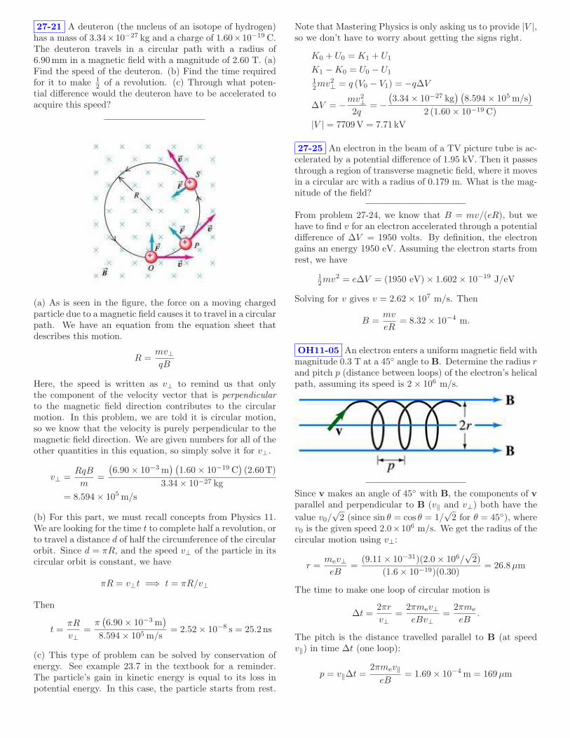
(a) As is seen in the figure, the force on a moving chargedparticle due to a magnetic field causes it to travel in a circularpath. We have an equation from the equation sheet thatdescribes this motion.
R =mv⊥qB
Here, the speed is written as v⊥ to remind us that onlythe component of the velocity vector that is perpendicular
to the magnetic field direction contributes to the circularmotion. In this problem, we are told it is circular motion,so we know that the velocity is purely perpendicular to themagnetic field direction. We are given numbers for all of theother quantities in this equation, so simply solve it for v⊥.
v⊥ =RqB
m=
(
6.90 × 10⁻³ m) (
1.60 × 10⁻¹⁹ C)
(2.60T)
3.34 × 10⁻²⁷ kg
= 8.594 × 10⁵ m/s
(b) For this part, we must recall concepts from Physics 11.We are looking for the time t to complete half a revolution, orto travel a distance d of half the circumference of the circularorbit. Since d = πR, and the speed v⊥ of the particle in itscircular orbit is constant, we have
πR = v⊥t =⇒ t = πR/v⊥
Then
t =πR
v⊥=
π(
6.90 × 10⁻³ m)
8.594 × 10⁵ m/s= 2.52 × 10⁻⁸ s = 25.2 ns
(c) This type of problem can be solved by conservation ofenergy. See example 23.7 in the textbook for a reminder.The particle’s gain in kinetic energy is equal to its loss inpotential energy. In this case, the particle starts from rest.
Note that Mastering Physics is only asking us to provide |V |,so we don’t have to worry about getting the signs right.
K0 + U0 = K1 + U1
K1 − K0 = U0 − U1
1
2mv2
⊥ = q (V0 − V1) = −q∆V
∆V = −mv2
⊥
2q= −
(
3.34 × 10⁻²⁷ kg) (
8.594 × 10⁵ m/s)
2 (1.60 × 10⁻¹⁹ C)
|V | = 7709V = 7.71 kV
27-25 An electron in the beam of a TV picture tube is ac-celerated by a potential difference of 1.95 kV. Then it passesthrough a region of transverse magnetic field, where it movesin a circular arc with a radius of 0.179 m. What is the mag-nitude of the field?
From problem 27-24, we know that B = mv/(eR), but wehave to find v for an electron accelerated through a potentialdifference of ∆V = 1950 volts. By definition, the electrongains an energy 1950 eV. Assuming the electron starts fromrest, we have
1
2mv2 = e∆V = (1950 eV) × 1.602 × 10⁻¹⁹ J/eV
Solving for v gives v = 2.62 × 10⁷ m/s. Then
B =mv
eR= 8.32 × 10⁻⁴ m.
OH11-05 An electron enters a uniform magnetic field withmagnitude 0.3 T at a 45 angle to B. Determine the radius rand pitch p (distance between loops) of the electron’s helicalpath, assuming its speed is 2 × 10⁶ m/s.
Since v makes an angle of 45 with B, the components of v
parallel and perpendicular to B (v‖ and v⊥) both have the
value v0/√
2 (since sin θ = cos θ = 1/√
2 for θ = 45), wherev0 is the given speed 2.0×10⁶ m/s. We get the radius of thecircular motion using v⊥:
r =mev⊥eB
=(9.11 × 10⁻³¹)(2.0 × 10⁶/
√2)
(1.6 × 10⁻¹⁹)(0.30)= 26.8µm
The time to make one loop of circular motion is
∆t =2πr
v⊥=
2πmev⊥eBv⊥
=2πme
eB.
The pitch is the distance travelled parallel to B (at speedv‖) in time ∆t (one loop):
p = v‖∆t =2πmev‖
eB= 1.69 × 10⁻⁴ m = 169µm

Physics 21Fall, 2011
Solution to HW-12
27-36 A straight, vertical wire carries a current of I =1.19 A downward in a region between the poles of a largesuperconducting electromagnet, where the magnetic field Bhas a magnitude of B = 0.591 T and is horizontal. Whatare the magnitude and direction of the magnetic force on asection of the wire with a length of l = 1.00 cm that is inthis uniform magnetic field, if the magnetic field direction is(a) east, (b) south, (c) 34 south of west?
The diagram shows the view looking down in the directionof the current, for an arbitrary orientation of B in the hori-zontal plane:
N
E
S
W
B
Fmag
I
We use the right hand rule to evaluate the magnetic force
Fmag = Il × B,
where l is a vector of length l, the length of the wire section,that points in the direction of the current. One can seethat for any horizontal B, the magnetic force will also behorizontal, and its direction will be 90 clockwise from B.(a) For B pointing east, the magnitude of Fmag is
Fmag = IlB = (1.19A)(0.010m)(0.591T) = 7.03mN
and the direction is south.(b) For B pointing south, Fmag is the same as in part (a),and the direction of Fmag is west.(c) For B pointing east, Fmag is the same as in part (a), andthe direction of Fmag is 34 west of north.
27-39 A thin, 51.0 cm long metal bar with mass 770 grests on, but is not attached to, two metallic supports ina uniform magnetic field with a magnitude of 0.470 T, asshown in the figure. A battery and a resistor of resistance26.0 Ω are connected in series to the supports. (a) Whatis the largest voltage the battery can have without break-ing the circuit at the supports? (b) The battery voltage hasthe maximum value calculated in part a. If the resistor sud-denly gets partially short-circuited, decreasing its resistanceto 2.70 Ω, find the initial acceleration of the bar.
The voltage V causes a current I = V/R to flow in thewire. Then the magnetic field exerts a force on the current-carrying wire that is in the upward direction.(a) The largest force that won’t break the circuit occurs whenthe upward magnetic force just balances the downward grav-itational force:
Fmag =∣∣∣IL × B
∣∣∣ = ILB =V
RLB = mg,
where I is the current through the wire, and L is a vectorthat points along the portion of the wire that is in the field.Solving for V , we find
V =mgR
LB= 819 V.
(b) When the resistance R drops to a lower value R′, thecurrent in the wire increases, and the upward force on thewire will exceed the downward gravitational force, leadingto a net upward force ma:
V LB
R′ − mg = ma.
Substituting the expression for V derived in part (a) into theexpression above leads to(
mgR
LB
)LB
R′ − mg = ma ⇒ gR
R′ − g = a
a = g
(R − R′
R′
)= 84.6 m/s2.
October 10, 2011

27-42 The plane of a rectangular loop of wire with a widthof 5.0 cm and a height of 8.0 cm is parallel to a magnetic fieldof magnitude 0.16 T. The loop carries a current of 6.3 A. (a)What torque acts on the loop? (b) What is the magneticmoment of the loop? (c) What is the maximum torque thatcan be obtained with the same total length of wire carryingthe same current in this magnetic field?
(b) The magnetic moment of the loop µ has magnitude IAand direction perpendicular to the loop. The magnitude is
µ = 2.52 × 10⁻² Am2
(a) The torque on the loop is τ = µ × B. Because µ isperpendicular to B, the magnitude of τ is
τ = µB = 4.03 × 10⁻³ Nm
(c) The maximum torque would be achieved for the loopwith the largest area for the available length of wire. Theshape of the optimum loop is a circle. If the sides are a andb, then the radius r of the circle satisfies
2πr = 2(a + b) ⇒ r =a + b
π= 0.13 m.
The magnitude of the maximum torque is
τmax = πr2IB = 5.42 × 10⁻³ Nm.
27-43 In the Bohr model of the hydrogen atom, in thelowest energy state the electron orbits the proton at a speedof v = 2.2 × 10⁶ m/s in a circular orbit of radius r = 5.3 ×10⁻¹¹ m. (a) What is the orbital period of the electron? (b)If the orbiting electron is considered to be a current loop,what is the current I? (c) What is the magnetic moment ofthe atom due to the motion of the electron?
(a) The time T to travel distance 2πr at speed v is
T = 2πr/v =2π(5.3 × 10⁻¹¹ m)
2.2 × 10⁶ m/s= 1.5 × 10⁻¹⁶ s
(b) Current is the amount of charge ∆Q passing a point intime ∆t. Since the electron with charge e passes any pointon its orbit once in time T ,
I = e/T =1.602 × 10⁻¹⁹ C1.5 × 10−16 s
= 1.1mA
(c) The magnitude of the magnetic moment of a current loopis the current I times the area of the loop:
µ = πr2I = π(5.3 × 10⁻¹¹ m)2(.00106A)= 9.3 × 10⁻²⁴ Am2
27-74 A wire 28.0 cm long lies along the z axis and car-ries a current of 8.60 A in the +z direction. The mag-netic field is uniform and has components Bx = −0.200 T,By = −0.968 T, and Bz = −0.327 T. Find the x, y, andz components of the magnetic force on the wire, and themagnitude of that force.
The force on the wire is given by
F = IL × B = ILk × (Bx i + By j + Bzk).
We can work out the cross products using k × i = j,k × j = −i, and k × k = 0. We get
F=IL(−By i + Bxj
)⇒ Fx = 2.33 T, Fy = −0.482 T
F =√
F 2x + F 2
y + 02 = 2.38 T

Physics 21Fall, 2011
Solution to HW-13
28-12 Two parallel wires are 5.00 cm apart and carry cur-rents in opposite directions, as shown in the figure. Findthe magnitude and direction of the magnetic field at pointP due to two 1.50-mm segments of wire that are oppositeeach other and each 8.00 cm from P .
dl
r-r'
dlr-r'
Use the Biot-Savart Law:
dB =µ0
4π
Idl × (r − r′)
|r − r′|3
,
where dl points in the direction of the current I, and r − r′
points from the current point to the field point (P ).We can evaluate dBtop and dBbottom (the contributions tothe total field from the top and bottom wires, respectively)separately and then add them. The diagram shows the vec-tors dl and r−r
′ for each of these contributions. The simplestway to evaluate the cross product is to use the right handrule for the direction, and to get the magnitude from theproducts of the magnitudes |dl| and |r − r
′| and the sin ofthe angle between the vectors.By the right hand rule, both dBtop and dBbottom point intothe page. The magnitudes of dl and r− r
′ are 0.0015 m and0.08 m, respectively, in each case. Since the wires are 5.0 cmapart, the sines of the angles in each case is 2.5/8.0. Hence
dBtop = 10−7 (12.0)(0.0015)(0.080)(2.5/8.0)
0.083
= 8.79 × 10⁻⁸ T
dBbottom = 10−7 (24.0)(0.0015)(0.080)(2.5/8.0)
0.083
= 1.76 × 10⁻⁷ T.
Since both contributions to the field point into the page, sodoes the sum, and
dBtotoal = dBtop + dBbottom = 2.64 × 10⁻⁷ T.
28-18 Two long, straight wires, one above the other, areseparated by a distance 2a and are parallel to the x axis. Letthe +y axis be in the plane of the wires in the direction fromthe lower wire to the upper wire. Each wire carries currentI in the +x direction. Find B, the net magnetic field of thetwo wires at the following points in the plane of the wires:(a) midway between the wires, (b) at a distance a above theupper wire, and (c) at a distance a below the lower wire.
x
y
zI
I
2a (a)
(b)
(c)
The magnitude of the magnetic field near a long wire is
B =µ0I
2πR,
where R is the perpendicular distance to the wire. The di-rection of the field is given by the right hand rule. For thepresent problem, we must add the vector contributions tothe field from each wire at each point (a), (b), and (c). Thedistances will be multiples of a.(a) At point (a), midway between the wires, the field fromthe top wire is µ0I/(2πa) into the page, and the field fromthe bottom wire is µ0I/(2πa) out of the page. The vectorsum is zero.
B = 0
(b) At point (b), a distance a above the top wire, the fieldfrom the top wire is µ0I/(2πa) out of the page, and the fieldfrom the bottom wire is µ0I/(2π3a) out of the page. Thesum is
B =µ0I
2π
(
1
a+
1
3a
)
=2µ0I
3πa(out of the page).
In terms of vector components,
B =2µ0I
3πak.
(c) At point (c), a distance a below the bottom wire, thefield from the bottom wire is µ0I/(2πa) into the page, andthe field from the top wire is µ0I/(2π3a) into the page.
B =2µ0I
3πa(into the page).
In terms of vector components,
B = −2µ0I
3πak.
October 12, 2011

Physics 21Fall, 2011
Solution to HW-14
Cancelling Magnetic Field Four very long, current-
carrying wires in the same plane intersect to form a squarewith side lengths of 39.0 cm, as shown in the figure. The cur-rents running through the wires are 8.0 A, 20.0 A, 10.0 A,and I. Find the magnitude and direction of the current Ithat will make the magnetic field at the center of the squareequal to zero.
The field point at the center of the square is equidistant fromall four wires. Let this distance be d = 1
2× 0.39 m. We just
have to keep track of the direction of each field using theright hand rule. Let out of the page be plus, and let I > 0correspond to up:
B out of page =µ0
2πd(−10 + I − 8 + 20)
Solving, we get I = −2 A, and the minus sign means I isdirected downward.
28-22 Two long, parallel transmission lines, L = 38.0 cmapart, carry currents I1 = 23.0-A and I2 = 78.0-A. Find alllocations where the net magnetic field of the two wires iszero if these currents are (a) in the same direction or (b) inopposite directions.
(a) (b)
L
xL
x
I1 I2I2I1
(a) Panel (a) of the diagram shows the two wires end onwhen the currents are in the same direction. L is the distancebetween the wires. The magnetic field lines due to each wireseparately are shown by the concentric circles (dashed for I1,solid for I2). The direction of the field follows from the righthand rule and is shown at selected points by an arrow nextto each circle. By looking at the directions of the two fieldsin various locations, it’s easy to see that for case (a), the
vector sum of the fields can only be zero on the line betweenthe wires.The magnitude of the field B a distance R from a long wirewith current I is B = µ0I/(2πR). The vector field will bezero at a point on the line between the wires a distance xfrom the left wire and L − x from the right wire, where themagnitudes of the fields are equal. Then
µ0I1
2πx=
µ0I2
2π(L − x)=⇒
I1
x=
I2
L − x
Solving this equation and substituting values leads to
x =
(
I1
I1 + I2
)
L =
(
23
23 + 78
)
38 cm = 8.7 cm
MasteringPhysics asks for the distance from the 78 A wirein the direction of the 23 A wire, which is L − x = 29.3 cmin our notation.(b) Panel (b) of the diagram is similar to panel (a); it showsthe two wires and the fields when the currents are in oppositedirections. In this case the vector sum of the fields can onlybe zero on the line connecting the wires, but outside thewires. We consider first a distance x to the left of I1; in thiscase the condition is
µ0I1
2πx=
µ0I2
2π(L + x)=⇒
I1
x=
I2
L + x
Solving this equation and substituting values leads to
x =
(
I1
I2 − I1
)
L =
(
23
78 − 23
)
38 cm = 15.9 cm
MasteringPhysics asks for the distance from the 78 A wirein the direction of the 23 A wire, which is L + x = 53.9 cmin our notation.What about a point to the right of I2 in panel (b)? We canset up the equation; a point a distance x to the right of I2
would be x + L from I1. Then
I2
x=
I1
L + x=⇒ x =
(
I2
I1 − I2
)
L
This solution won’t work in our case. I2 > I1, so x < 0,which contradicts our initial assumption that x is a positivedistance. Therefore there are no other solutions.Comparing the two solutions we have obtained for part (b),one can see that a general way of writing the solution is
x =
(
I<
I> − I<
)
L,
where I< (I>) is the lesser (greater) of I1 and I2. The pointwhere the field is zero is outside the two currents, a distancex from the wire with the smaller current.
October 14, 2011

Wire and Square Loop A square loop of wire with side
length a carries a current I1. The center of the loop is locateda distance d from an infinite wire carrying a current I2. Theinfinite wire and loop are in the same plane; two sides of thesquare loop are parallel to the wire and two are perpendicularas shown. (a) What is the magnitude F of the net force onthe loop? (b) The magnetic moment µ of a current loopis defined as the vector whose magnitude equals the area ofthe loop times the magnitude of the current flowing in it(µ = IA), and whose direction is perpendicular to the planein which the current flows. Find the magnitude F of theforce on the loop from Part (a) in terms of the magnitude ofits magnetic moment.
(a) The B field is into the page everywhere on the right ofthe wire in the plane of the square loop. Its magnitude isgiven by B = µ0I2/2πR, where R is the distance to the wire.The diagram shows the forces on the left and right hand sideof the loop from this field. These forces are obtained fromF = Il × B, and the magnitudes are
Fleft = I1aB = I1aµ0I2
2π(d − a/2)
Fright = I1aB = I1aµ0I2
2π(d + a/2)
There is also an upward force (Ftop) and (Ftop), but theyare equal in magnitude and oppositely directed. Hence thenet force is the vector sum of the forces to the left and tothe right. The net force is to the left and has magnitude
Fleft − Fright =µ0I1I2a
2π
(
1
d − a/2−
1
d + a/2
)
=µ0I1I2
2π
a2
d2− a2/4
(b) The magnitude of the magnetic moment µ of the loop isthe current times the area, or
µ = I1a2.
We can write the net force in terms of µ as
Fleft − Fright =µ0
2π
µI2
d2− a2/4
28-26 Two long, parallel wires are separated by a distanceof d = 2.70 cm. The force per unit length that each wireexerts on the other is 4.10 × 10⁻⁵ N/m, and the wires repeleach other. The current in one wire is I1 = 0.700 A. (a)What is the current in the second wire? (b) Are the twocurrents in the same direction or in opposite directions?
I1
I2
B1
Let’s assume that the currents flow in the directions shown,and we’ll show that the force between the wires is repulsive.The magnitude of the magnetic field B1 of wire 1 at wire 2is
B1 =µ0I1
2πd,
and from the rh rule, B1 points into the page. The magni-tude of the force F that B1 exerts on a length L of wire 2is
F = I2LB1 = I2Lµ0I1
2πd,
and by the rh rule one can see that the direction is downward.One can go through a similar argument to find that the forceon the upper wire has the same magnitude and is upward,so the forces make the wires repel each other.The force per unit length is
F
L=
µ0
2π
I1I2
d
The question asks for I2, so
I2 =2π
µ0
(
F
L
)
d
I1
=0.5×10⁷(
4.10× 10⁻⁵) 0.027
0.7=7.91A
In general, the currents must flow in the opposite direction.
28-27 The wires in a household lamp cord are typicallyd = 2.5 mm apart center to center and carry equal currentsin opposite directions. (a) If the cord carries current to a 100watt light bulb connected across a 120 V potential difference,what force per meter does each wire of the cord exert on theother? (Model the lamp cord as a very long straight wire.)(b) Is the force attractive or repulsive? (c) Is this force largeenough so it should be considered in the design of lamp cord?
Since P = IV , the current in each wire is I = P/V =100W/120V = 0.833A.(a) The force per unit length is given by the formula derivedin problem 28-26, with both currents equal:
F
L=
µ0
2π
I2
d= 2 × 10⁻⁷ (0.833)2
0.0025= 5.56 × 10⁻⁵ N/m
(b) The force will be repulsive.(c) No. The force is small compared to the gravitationalforce. If we guess that a meter of wire weighs a few ounces,say 0.1 kg, then
mg = (0.1 kg)9.81m/s2∼ 1N,
much larger than the magnetic force.

Physics 21Fall, 2011
Solution to HW-15
28-32 A solid conductor with radius a is supported by in-sulating disks on the axis of a conducting tube with innerradius b and outer radius c. The central conductor and tubecarry equal currents I in opposite directions. The currentsare distributed uniformly over the cross sections of each con-ductor. (a) Derive an expression for the magnitude of themagnetic field at points outside the central, solid conductor,but inside the tube (a < r < b). (b) Derive an expressionfor the magnitude of the magnetic field at points outside thetube (r > c).
(a) This problem is best answered with Ampere’s Law
∮
B · dl = µ0Iencl
Chose a circular line integral path with radius r between thecenter and outer conductor, then by symmetry we expectthe value of B to be constant around the path. The onlycurrent enclosed is the current I in the center conductor.
2πrBinside = µ0I
Solving for B,
Binside =µ0I
2πr=
(
2 × 10⁻⁷) I
r
(b) Taking a similar approach for this problem, choose acurrent loop with radius r > c. The total current enclosed isnow zero because the two currents I in each conductor aregoing in opposite directions.
Boutside = 0
28-34 A closely wound coil has a radius a = 5.90 cm andcarries a current I = 3.30 A. How many turns must it haveif, at a point on the coil axis 6.20 cm from the center of thecoil, the magnetic field is 6.58 × 10⁻⁴ T?
The magnitude of the magnetic field at the point x on theaxis of a single circular loop with a radius a and current I is
B =µ0Ia2
2(x2 + a2)3/2.
For a loop with N turns, the total magnetic field will be Ntimes this magnitude. So we can determine the number ofturns by solving for N to get:
N =2B(x2 + a2)3/2
µ0Ia2
=2(.000658)
(
.0622 + .0592)3/2
(4π × 10−7)(3.30)(.059)2= 57
October 18, 2011

28-36 The figure shows, in cross section, several conductorsthat carry currents through the plane of the figure. Thecurrents have the magnitudes I1 = 4.0 A, I2 = 6.5 A, andI3 = 2.1 A, and the directions shown. Four paths, labeled a,b, c, and d, are shown. What is the line integral
∮
B · dl foreach of the four paths? The integral involves going aroundthe path in the counterclockwise direction.
Use Ampere’s Law,
∮
B · dl = µ0Iencl,
where the positive direction of current flow is out of the pagesince the integral is done counterclockwise.(a)
Iencl = 0 ⇒
∮
B · dl = 0
(b)
Iencl = −I1 ⇒
∮
B · dl = −5.03 × 10⁻⁶ Tm.
(c)
Iencl = I2 − I1 ⇒
∮
B · dl = 3.14 × 10⁻⁶ Tm.
(d)
Iencl = I2 + I3 − I1 ⇒
∮
B · dl = 5.78 × 10⁻⁶ Tm.
28-41 A solenoid is designed to produce a magnetic fieldof 2.00 × 10⁻² T at its center. It has a radius of 1.60 cmand a length of 33.0 cm, and the wire can carry a maximumcurrent of 13.5 A. (a) What minimum number of turns perunit length must the solenoid have? (b) What total lengthof wire is required?
(a) The magnitude of the magnetic field inside a solenoidis given by B = µ0nI, where n is the number of turns perunit length. Solving this equation for n = B/µ0I, we cansee that the minimum n will occur when the current is at itsmaximum;
n =B
µ0Imax
=2.00 × 10⁻² T
(4π × 10−7 Wb
A·m)(13.5A)
= 1180turns
m.
(b) The total length of wire L will be the total number ofloops times the length of one loop, which is the circumfer-ence, L = N2πr. The total number of loops is simply thenumber of turns per length times the total length of thesolenoid N = nl. Thus the total length of the wire is
L = nl2πr = (1180m−1)(.33m)(2π)(.016m) = 39.1m
28-45 A wooden ring whose mean diameter is 16.0 cm iswound with a closely spaced toroidal winding of 585 turns.(a) Compute the magnitude of the magnetic field at the cen-ter of the cross section of the windings when the current inthe windings is 0.655 A.
(a) In the center of the windings, the strength of the mag-netic field can be found using the formula derived in the classlecture:
B = µ0nI
This is the same formula used for a solenoid; a toroid isbasically a rolled up solenoid. n is the number of turns perunit length along the toroid. To calculate n, we use thenumber of turns divided by the circumference of the toroid:
n =585
π 0.16
B = µ0
585
π 0.160.655 = 9.58 × 10⁻⁴ T

Physics 21Fall, 2011
Solution to HW-16
28-48 The current in the windings of a toroidal solenoidis 2.400 A. There are N = 500 turns and the mean radius isr = 25.00 cm. The toroidal solenoid is filled with a magneticmaterial. The magnetic field inside the windings is foundto be 1.940 T. (a) Calculate the relative permeability. (b)Calculate the magnetic susceptibility of the material thatfills the toroid.
(a) The magnetic field inside a tightly wound toroidalsolenoid is
B = Kmµ0nI = Km
µ0NI
2πr,
where n is the number of turns per unit length and N is thetotal number of turns.Solving the last equation for Km, we get
Km =2πrB
µ0NI=
2π · 0.25 · 1.94
(4π × 10−7) 500 · 2.4= 2021.
(b) The magnetic susceptibility is
χm = Km − 1
thus the answer is 2020.
28-52 A long, straight wire carries a current of 2.50 A. Anelectron is traveling in the vicinity of the wire. At the instantwhen the electron is 4.50 cm from the wire and traveling witha speed of 6.00× 10⁴ m/s directly toward the wire, what arethe magnitude and direction (relative to the direction of thecurrent) of the force that the magnetic field of the currentexerts on the electron?
I
v
B F
The magnetic field due to the wire has magnitude
B =µ0I
2πr
and direction (from the rh rule) out of the page at the loca-tion of the electron as shown. The force on the electron isgiven by
F = qv × B = −ev × B.
F is in the direction shown in the diagram. Note that thenegative sign of the electron makes F in the opposite direc-tion from v × B. The vectors F, v, and B are mutuallyperpendicular, so the magnitude of F is
F = evB =evµ0I
2πr
Using SI units,
F =(1.602 × 10⁻¹⁹)(60000)(4π × 10−7)(2.5)
2π(.045)N
= 1.07 × 10⁻¹⁹ N
The magnetic field exerts a force in the same direction asthe current.
28-55 Two identical circular, wire loops 35.0 cm in di-ameter each carry a current of 2.30A in the same direction.These loops are parallel to each other and are 22.0 cm apart.Line ab is normal to the plane of the loops and passes throughtheir centers. A proton is fired at 2750 m/s perpendicularto line ab from a point midway between the centers of theloops. Find the magnitude of the magnetic force these loopsexert on the proton just after it is fired.
This problem involves the magnetic force on a movingcharged particle, F = qv × B. The trick is to find the mag-netic field at the position of the particle due to the two loops.The particle is located on line ab. From the description ofthe loops, we know that line ab is on the axis of both loops.Section 28-5 in the textbook shows how to calculate the mag-netic field along the axis of a loop. In particular, for a loopof radius a, carrying a current I, the magnetic field along theaxis a distance x from the loop is given by equation 28.15:
B =µ0Ia2
2 (x2 + a2)3/2
The direction of the magnetic field is along the axis as de-termined by the right hand rule. Notice that the directionof the force is the same regardless of which side of the loopis particle is located at.Since the particle is located equidistant from the two loops,and because the loops carry the same current in the samedirection, each loop contributes the same magnitude and di-rection of magnetic field. The total magnetic field is thustwice the magnetic field due to a single loop.We only need to find the magnitude of the force, F =qvB sin θ = qvB sin 90 = qvB, since the direction of v isperpendicular to the loop axis, and the direction of B isalong the loop axis.
F = qv
(
2µ0Ia2
2 (x2 + a2)3/2
)
= qvµ0Ia2
(x2 + a2)3/2
=(
1.60 × 10⁻¹⁹ C)
(2750m/s)
×
(
4π × 10−7 T · m/A)
(2.30A) (.175m)2
(
(.110m)2
+ (.175m)2)3/2
= 4.42 × 10⁻²¹ N
October 21, 2011

28-63 Two long, parallel wires hang by 4.00-cm-long cordsfrom a common axis (see the figure ). The wires have a massper unit length of 1.10 × 10⁻² kg/m and carry the samecurrent in opposite directions. (a) What is the current ineach wire if the cords hang at an angle of 6.00 with thevertical?
(a) Two parallel wires with currents running in opposite di-rections exert a repulsive force on one another. Using theformula for the magnetic field at a distance r from a longwire, B = µ0I/(2πr), and the force F on a length L of wirefrom a magnetic field B perpendicular to the wire, F = ILB,one can find the force per unit length on one wire due to thecurrent in the other:
F
L=
µ0II ′
2πr.
Viewing a wire end-on allows us to construct a free bodydiagram involving the gravitational force, tension, and themagnetic force.
The sum of the forces can then be written as∑
Fy = T cos θ − mg = 0 =⇒ T = mg/ cos θ
∑
Fx = F − T sin θ = 0 =⇒ F = T sin θ= mg tan θ,
where F denotes the force on a length of wire L. Now weuse the expression for the magnetic force F and the linearmass density, λ = m/L,
F =µ0I
2L
2πr= mg tan θ = λLg tan θ
µ0I2L
2πr= λLg tan θ =⇒ I =
√
1
µ0
2πrλg tan θ
Note the Ls cancel. The distance r between the two wires istwice the base leg of the right triangle that is formed whenthe 4.00-cm cord hangs at 6 with respect to the vertical.
r = 2 l sin θ = 2(0.040 m) sin(6.00) = 8.362 × 10⁻³ m.
Now we substitute this r and µ0 = 4π × 10−7 Tm/A,λ = 1.10 × 10⁻² kg/m, g = 9.8m/s2, and θ = 6.0 intothe expression for I and find
I = 21.8A,
When I is increased, the angle θ from the vertical increases.A large current is required for even the small displacementseen here.
29-5 A circular loop of wire with a radius of r = 14.0 cmand oriented in the horizontal xy plane is located in a regionof uniform magnetic field. A field of magnitude B = 1.8 T isdirected along the positive z direction, which is upward. (a)If the loop is removed from the field region in a time intervalof 2.0 ms, find the average of the emf that will be inducedin the wire loop during the extraction process. (b) If thecoil is viewed looking down on it from above, is the inducedcurrent in the loop clockwise or counterclockwise?
(a) The induced emf is given by Faraday’s Law:
E = −dΦ
dt=⇒ |E| ∼
∣
∣
∣
∣
∆Φ
∆t
∣
∣
∣
∣
.
The change in flux ∆Φ is the difference between the finalflux and the initial flux, and ∆t is 2.0µs.Since the field B is initially perpendicular to the loop, theinitial flux Φi through the loop is just the area of the circularloop times the magnetic field:
Φi =
∫
B · dA = πr2B.
After the loop is removed from the magnetic field, the finalflux Φf is zero. We get the absolute value of the emf from
|E| =
∣
∣
∣
∣
Φf − Φi
∆t
∣
∣
∣
∣
=
∣
∣
∣
∣
0 − Φi
∆t
∣
∣
∣
∣
=Φi
∆t=
πr2B
∆t
=π(0.14m)2 × 1.8T
0.002 s= 55V.
(b) The direction of the induced current I is obtained usingLenz’s Law. The direction of I must oppose the changein flux. Originally, the flux was determined by the field B
pointing up (as one looks down on the loop). When theloop is removed from the field, the induced current will bein the direction that will restore an upward pointing field.Therefore the current is counterclockwise.

Physics 21Fall, 2011
Solution to HW-17
29-7 The current in the long, straight wire AB shown inthe figure is upward and is increasing steadily at a rate di/dt.(a,b) At an instant when the current is i, what are the mag-nitude and direction of the field B at a distance r to theright of the wire? (c) What is the flux dΦB through thenarrow shaded strip? (d) What is the total flux through theloop? (e) What is the induced emf in the loop? (f) Evalu-ate the numerical value of the induced emf if a = 12.0 cm,b = 36.0 cm, L = 24.0 cm, and di/dt = 9.60 A/s.
(a,b)
B =µ0i(t)
2πrinto page (by right hand rule)
(c)
dΦ = B dA =µ0i(t)
2πrLdr
(d) Integrate
Φ =
∫
b
a
dΦ =µ0i(t)L
2π
∫
b
a
dr
r=
µ0i(t)L
2πln
b
a
(e)
|E| =dΦ
dt=
µ0L
2π
di
dtln
b
a
(f)
(2 × 10⁻⁷)(0.24m)(9.6)
(
ln36
12
)
= 5.06 × 10⁻⁷ V
What will be the direction of the current? Counterclockwise.
29-8 A flat, circular, steel loop of radius 75 cm is at restin a uniform magnetic field, as shown in an edge-on viewin the figure. The field is changing with time, according toB(t) = (1.4T)e−(0.057s
−1)t. (a) Find the emf induced in theloop as a function of time (assume t is in seconds). (b) Whenis the induced emf equal to 1/20 of its initial value? (c) Findthe direction of the current induced in the loop, as viewedfrom above the loop.
(a) We can find the emf induced in the loop using
∮
E · dl = −d
dt
∫
B · dA = −dΦ
dt,
where the integral of E · dl is the induced emf. Because themagnetic field makes a 60 degree angle with the loop, we canwrite
∫
B · dA = Φ = B(t)A sin(60)
where A = πr2 is the area of the loop. Because the areaof the loop doesn’t change with time, dΦ/dt = πr2dB/dt,where
d
dtB(t) = (1.4)(−0.057)e−0.057t
Putting these pieces together results in:
E = −πr2 sin(60)(1.4)(−0.057)e−0.057t = 0.122e−0.057t
We usually take E to be the magnitude of the emf, and don’tworry about the sign. The negative sign is related to thepolarity of the voltage.(b) Now that we have an expression for the induced emf asa function of time, we can solve for t at a particular emf.
1
20= e−0.057t =⇒ t = ln 20/(0.057 s−1) = 52.6 s
(c) According to Lenz’s Law, the induced emf will causecurrent to flow in the direction that opposes the change inmagnetic flux. Because the magnitude of the magnetic fielddirected upwards through the loop is decreasing with time,the induced emf will cause a current to flow in a directionthat will cause a magnetic field upward. For that to happen,the current must flow in a counterclockwise direction.
October 27, 2011
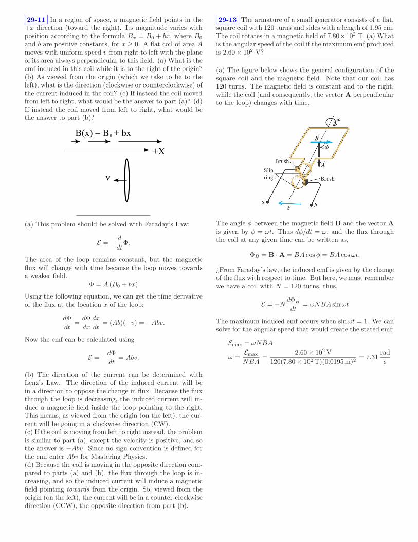
29-11 In a region of space, a magnetic field points in the+x direction (toward the right). Its magnitude varies withposition according to the formula Bx = B0 + bx, where B0
and b are positive constants, for x ≥ 0. A flat coil of area Amoves with uniform speed v from right to left with the planeof its area always perpendicular to this field. (a) What is theemf induced in this coil while it is to the right of the origin?(b) As viewed from the origin (which we take to be to theleft), what is the direction (clockwise or counterclockwise) ofthe current induced in the coil? (c) If instead the coil movedfrom left to right, what would be the answer to part (a)? (d)If instead the coil moved from left to right, what would bethe answer to part (b)?
+X
B(x) = B + bx0
v
(a) This problem should be solved with Faraday’s Law:
E = −d
dtΦ.
The area of the loop remains constant, but the magneticflux will change with time because the loop moves towardsa weaker field.
Φ = A (B0 + bx)
Using the following equation, we can get the time derivativeof the flux at the location x of the loop:
dΦ
dt=
dΦ
dx
dx
dt= (Ab)(−v) = −Abv.
Now the emf can be calculated using
E = −dΦ
dt= Abv.
(b) The direction of the current can be determined withLenz’s Law. The direction of the induced current will bein a direction to oppose the change in flux. Because the fluxthrough the loop is decreasing, the induced current will in-duce a magnetic field inside the loop pointing to the right.This means, as viewed from the origin (on the left), the cur-rent will be going in a clockwise direction (CW).(c) If the coil is moving from left to right instead, the problemis similar to part (a), except the velocity is positive, and sothe answer is −Abv. Since no sign convention is defined forthe emf enter Abv for Mastering Physics.(d) Because the coil is moving in the opposite direction com-pared to parts (a) and (b), the flux through the loop is in-creasing, and so the induced current will induce a magneticfield pointing towards from the origin. So, viewed from theorigin (on the left), the current will be in a counter-clockwisedirection (CCW), the opposite direction from part (b).
29-13 The armature of a small generator consists of a flat,square coil with 120 turns and sides with a length of 1.95 cm.The coil rotates in a magnetic field of 7.80×10² T. (a) Whatis the angular speed of the coil if the maximum emf producedis 2.60 × 10² V?
(a) The figure below shows the general configuration of thesquare coil and the magnetic field. Note that our coil has120 turns. The magnetic field is constant and to the right,while the coil (and consequently, the vector A perpendicularto the loop) changes with time.
The angle φ between the magnetic field B and the vector A
is given by φ = ωt. Thus dφ/dt = ω, and the flux throughthe coil at any given time can be written as,
ΦB = B · A = BA cos φ = BA cos ωt.
¿From Faraday’s law, the induced emf is given by the changeof the flux with respect to time. But here, we must rememberwe have a coil with N = 120 turns, thus,
E = −NdΦB
dt= ωNBA sinωt
The maximum induced emf occurs when sin ωt = 1. We cansolve for the angular speed that would create the stated emf:
Emax = ωNBA
ω =Emax
NBA=
2.60 × 10² V
120(7.80 × 10² T)(0.0195m)2= 7.31
rad
s

29-17 Consider the system shown below. (a) Using Lenz’slaw, determine the direction of the current in resistor ab ofthe figure when switch S is opened after having been closedfor several minutes. (b) Using Lenz’s law, determine thedirection of the current in resistor ab of the figure when coilB is brought closer to coil A with the switch closed. (c)Using Lenz’s law, determine the direction of the current inresistor ab of the figure when the resistance of R is decreasedwhile the switch remains closed.
(a) The current will flow from the positive terminal of thebattery when S is closed. Thus, the current flowing in coilA will produce a magnetic field inside coil A pointing tothe right (and also to the right inside coil B). When S isthen opened, the current will stop flowing and the magneticfield it produces will decrease. Lenz’s Law says that the Einduced in the coil B will oppose the change in magnetic fluxby causing current that will create an additional magneticfield to the right. Thus, by the right hand rule the currentin coil B will flow from a to b.(b) When S is closed, coil A produces a magnetic field insidethe coils pointing to the right. As coil B is brought closer toA, the magnetic field inside coil B becomes stronger, so theflux becomes larger. The E induced in coil B will oppose thechange in magnetic flux by causing current that will createadditional magnetic field to the left. By the right hand rule,the current in coil B will flow from b to a.(c) If the resistance in R is decreased, the relation I = V/Rtells us that the current will increase, since the battery volt-age V does not change. When the current through coil Aincreases, the magnetic field directed to the right will alsoincrease. The E induced in coil B will oppose the change inmagnetic flux by causing current that will create additionalmagnetic field to the left. By the right hand rule, the currentin coil B will flow from b to a. [This argument is exactly thesame as the one used in part (b)].
29-20 A 1.60 m long metal bar is pulled to the right at asteady 4.5 m/s perpendicular to a uniform, 0.755 T magneticfield. The bar rides on parallel metal rails connected throughR = 26.0Ω, as shown in the figure, so the apparatus makesa complete circuit. You can ignore the resistance of the barand the rails. (a) Calculate the magnitude of the emf inducedin the circuit. (b) Find the direction of the current inducedin the circuit. (c) Calculate the current through the resistor.
The flux at any time is the area of the loop times the mag-nitude of the magnetic field B, and we let L be the lengthof the bar. In a time ∆t the area of the circuit will increaseby L∆x, where ∆x and ∆t are related to the speed of thebar by v = ∆x/∆t.(a) The emf is given by
E = ∆Φ/∆t = BL∆x/∆t = BLv
= 0.755T × 1.60m × 4.5m/s = 5.44V
(b) Pulling the rod increases the flux by adding magneticfield directed into the page. By Lenz’ Law, the inducedcurrent must then produce a magnetic field inside the loopdirected out of the page. The current must therefore becounterclockwise.(c) By Ohm’s Law,
E = IR ⇒ I = 5.44V/26.0Ω = 0.21A

Physics 21Fall, 2011
Solution to HW-18
30-7 At the instant when the current in an inductor is in-creasing at a rate of 6.45 × 10⁻² A/s, the magnitude of theself-induced emf is 1.65 × 10⁻² V. (a) What is the induc-tance of the inductor? (b) If the inductor is a solenoid with405 turns, what is the average magnetic flux through eachturn when the current is 0.715A?
(a) In the class lecture we applied Faraday’s Law to asolenoid with N turns. The self-induced emf is E = −N dΦB
dt ,and we defined the self-inductance L by
E = −Ldi
dt
Here we aren’t concerned with the direction of the emf, onlythe magnitude. Therefore we can substitute the given valuesto obtain
L =E
di/dt=
1.65 × 10⁻² V
6.45 × 10⁻² A/s
= 0.256H
(b) For this part we must notice that since the flux throughone loop of a solenoid of length l is given by
ΦB = BA = µ0N
liA,
we can rewrite the expression for the inductance L given onthe equation sheet in terms of the flux,
L = µ0N2
lA = Nµ0
N
lA = N
ΦB
i.
Note that the relation above,
L = NΦB
i,
is in fact the definition used in the book for L [Eq. (30.6)].We can use it to answer this problem by solving for ΦB.
ΦB =Li
N=
(0.256H) (0.715A)
405
= 4.52 × 10⁻⁴ Wb
30-19 An inductor with an inductance of 2.50 H and aresistance of 8.00Ω is connected to the terminals of a batterywith an emf of 6.00 V and negligible internal resistance. Find(a) the initial rate of increase of current in the circuit; (b) therate of increase of current at the instant when the currentis 0.500 A; (c) the current 0.250 s after the circuit is closed;(d) the final steady-state current.
(a) Applying Kirchhoff’s Law, we find the loop equation is
E − iR − Ldi
dt= 0 =⇒ di
dt=
E − iR
L.
The initial condition is that i = 0 at t = 0, so at that time
di
dt=
EL
=6V
2.5H= 2.4A/s.
(b) Using the loop equation again for i = 0.5A,
di
dt=
E − iR
L=
6V − (0.5A × 8Ω)
2.5H= 0.8A/s.
(c) Using the general solution for the loop equation, we have
i =ER
(
1 − e−(R/L)t)
=6V
8Ω
(
1 − e−(8Ω/2.5 H)0.25 s)
= 0.413A.
(d) The general solution shows that as t → ∞, the exponen-tial term vanishes. Then
i =ER
=6V
8Ω= 0.75A.
30-29 A 7.60 nF capacitor is charged up to 13.0V, thendisconnected from the power supply and connected in seriesthrough a coil. The period of oscillation of the circuit is thenmeasured to be 9.00×10⁻⁵ s. (a) Calculate the inductance ofthe coil. (b) Calculate the maximum charge on the capacitor.(c) Calculate the total energy of the circuit. (d) Calculatethe maximum current in the circuit.
(a) The resonant frequency of an LC circuit is related to L,C, and the period of the oscillations T by
ω =1√LC
=2π
T.
(The frequency formula is given on the equation sheet; forthis case R = 0.) Solving for L leads to
L =T 2
4π2C=
(9.00 × 10⁻⁵ s)2
4π2(7.60 × 10⁻⁹ F)= 2.70 × 10⁻² H.
(b) The capacitor has its maximum charge when it is initiallycharged to V = 13V:
Q = CV = (7.60 × 10⁻⁹ F)(13V) = 9.88 × 10⁻⁸ C.
(c) Energy is conserved, and the total energy of the oscillatoris the energy initally stored in the capacitor:
U = 12CV 2 = 1
2 (7.60 × 10⁻⁹ F)(13V)2 = 6.42 × 10⁻⁷ J.
(d) In the LC oscillator, the energy swings back and forthbetween the capacitor and the inductor. At one point, thetotal energy U of the circuit is all in the inductor. At thattime, the current through the inductor is a maximum, and wecan use the expression for energy in the inductor, U = 1
2LI2,and solve for I:
I =
√
2U
L
=
√
2(6.42 × 10⁻⁷ J)
(2.70 × 10⁻² H)= 6.90 × 10⁻³ A = 6.90mA.
October 28, 2011
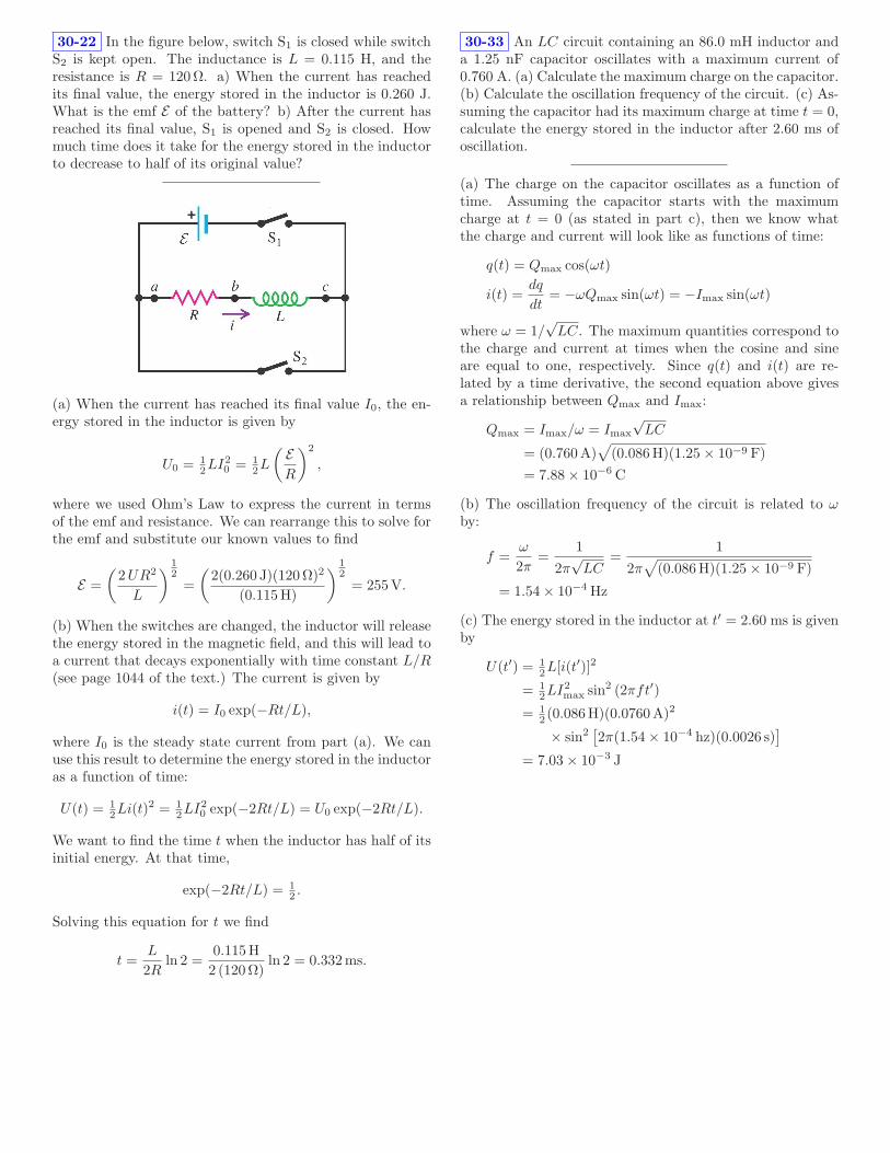
30-22 In the figure below, switch S1 is closed while switchS2 is kept open. The inductance is L = 0.115 H, and theresistance is R = 120Ω. a) When the current has reachedits final value, the energy stored in the inductor is 0.260 J.What is the emf E of the battery? b) After the current hasreached its final value, S1 is opened and S2 is closed. Howmuch time does it take for the energy stored in the inductorto decrease to half of its original value?
(a) When the current has reached its final value I0, the en-ergy stored in the inductor is given by
U0 = 12LI2
0 = 12L
(
ER
)2
,
where we used Ohm’s Law to express the current in termsof the emf and resistance. We can rearrange this to solve forthe emf and substitute our known values to find
E =
(
2UR2
L
)
12
=
(
2(0.260 J)(120Ω)2
(0.115H)
)
12
= 255V.
(b) When the switches are changed, the inductor will releasethe energy stored in the magnetic field, and this will lead toa current that decays exponentially with time constant L/R(see page 1044 of the text.) The current is given by
i(t) = I0 exp(−Rt/L),
where I0 is the steady state current from part (a). We canuse this result to determine the energy stored in the inductoras a function of time:
U(t) = 12Li(t)2 = 1
2LI20 exp(−2Rt/L) = U0 exp(−2Rt/L).
We want to find the time t when the inductor has half of itsinitial energy. At that time,
exp(−2Rt/L) = 12 .
Solving this equation for t we find
t =L
2Rln 2 =
0.115H
2 (120Ω)ln 2 = 0.332ms.
30-33 An LC circuit containing an 86.0 mH inductor anda 1.25 nF capacitor oscillates with a maximum current of0.760 A. (a) Calculate the maximum charge on the capacitor.(b) Calculate the oscillation frequency of the circuit. (c) As-suming the capacitor had its maximum charge at time t = 0,calculate the energy stored in the inductor after 2.60 ms ofoscillation.
(a) The charge on the capacitor oscillates as a function oftime. Assuming the capacitor starts with the maximumcharge at t = 0 (as stated in part c), then we know whatthe charge and current will look like as functions of time:
q(t) = Qmax cos(ωt)
i(t) =dq
dt= −ωQmax sin(ωt) = −Imax sin(ωt)
where ω = 1/√
LC. The maximum quantities correspond tothe charge and current at times when the cosine and sineare equal to one, respectively. Since q(t) and i(t) are re-lated by a time derivative, the second equation above givesa relationship between Qmax and Imax:
Qmax = Imax/ω = Imax
√LC
= (0.760A)√
(0.086H)(1.25 × 10⁻⁹ F)
= 7.88 × 10⁻⁶ C
(b) The oscillation frequency of the circuit is related to ωby:
f =ω
2π=
1
2π√
LC=
1
2π√
(0.086H)(1.25 × 10⁻⁹ F)
= 1.54 × 10⁻⁴ Hz
(c) The energy stored in the inductor at t′ = 2.60 ms is givenby
U(t′) = 12L[i(t′)]2
= 12LI2
max sin2 (2πft′)
= 12 (0.086H)(0.0760A)2
× sin2[
2π(1.54 × 10⁻⁴ hz)(0.0026 s)]
= 7.03 × 10⁻³ J

Physics 21Fall, 2011
Solution to HW-19
29-34 A dielectric of permittivity 3.3 × 10⁻¹¹ F/m com-pletely fills the volume between two capacitor plates. For t >0 the electric flux through the dielectric is (7800 V m/s3)t3.The dielectric is ideal and nonmagnetic; the conduction cur-rent in the dielectric is zero. At what time does the displace-ment current in the dielectric equal 23 µA?
For a charging capacitor we have the equation for displace-ment current iD = ǫ0
dΦE
dt. When a dielectric is between the
capacitor plates, we multiply ǫ0 by the dielectric constant Kto get the permittivity of the material ǫ = Kǫ0. Thus wehave iD = ǫdΦE
dt. The function for the electric flux can then
be substituted:
iD = ǫd
dt
(
(7800 V m/s3)t3)
= ǫ(7800 V m/s3)d
(
t3)
dt
= ǫ(7800 V m/s3)(3)t2
Solving this for time:
t =
√
iDǫ(7800 V m/s3)(3)
=
√
23 × 10−6
3.3 × 10⁻¹¹(7800 V m/s3)(3)= 5.5 s
29-51 As a new electrical engineer for the local power com-pany, you are assigned the project of designing a generatorof sinusoidal ac voltage with a maximum voltage of 120 V.Besides plenty of wire, you have two strong magnets thatcan produce a constant uniform magnetic field of 1.8 T overa square area with a length of 10.4 cm on a side when themagnets are separated by a distance of 12.1 cm. The basicdesign should consist of a square coil turning in the uniformmagnetic field. To have an acceptable coil resistance, thecoil can have at most 450 loops.
We can use Faraday’s law to calculate the induced EMF.
∮
E · dl = − d
dt
∫
B · dA = −dΦ
dt,
The flux through a square loop perpendicular to the mag-netic field with the maximum possible dimensions and Nloops of wire will be ΦB = NBA, where A is the area. Ifthe loop is rotated within the magnetic field, then the fluxthrough the loop will change because number of field linesgoing through the loop will be changing. Rotating at anangular frequency of ω, the flux will change with time:
ΦB(t) = NBA cos(ωt)
The time derivative of this gives the induced EMF:
E = −dΦB
dt= NBAω sin(ωt)
The amplitude is then NBAω. Solving for ω
ω =E
NBA=
120V
450 × 1.8 × .1042= 13.7 rad/sec
Mastering physics wants an answer in revolutions perminute, so the conversion is:
13.7rad
sec· 60 sec
1min· 1 rev
2π rad= 130.8 rpm
November 4, 2011

31-6 A capacitance C and an inductance L are operated atthe same angular frequency. (a) At what angular frequencywill they have the same reactance? (b) If L = 4.80 mHand C = 3.70µF, what is the numerical value of the angularfrequency in part (a)? (c) What is the reactance of eachelement?
(a) Equate the reactances and solve for ω:
1
ωC= ωL ⇒ 1 = ω2LC ⇒ ω =
1√LC
.
(b) Substituting numbers,
ω =1
√
(4.80 × 10⁻³)(3.70 × 10⁻⁶)= 7.50 × 10³ rad/s.
(c) Again substituting numbers,
1
ωC= ωL = 36.0Ω.
31-10 You want the current amplitude through an inductorwith an inductance of 5.00 mH (part of the circuitry for aradio receiver) to be 2.10 mA when a sinusoidal voltage withan amplitude of 12.0 V is applied across the inductor. (a)What frequency is required?
(a) The frequency f is related to angular frequency ω by theequation ω = 2πf . The amplitude of the voltage across theinductor is VL = ILω = IL2πf . Thus the frequency is
f =VL
2πIL=
12.0V
2π(2.10 × 10⁻³ A)(5.00 × 10⁻³ H)
= 182 kHz
31-14 You have a 180Ω resistor and a 0.430H inductor.Suppose you take the resistor and inductor and make a seriescircuit with a voltage source that has a voltage amplitude of28.0V and an angular frequency of 250 rad/s. (a) What isthe impedance of the circuit? (b) What is the current ampli-tude? (c) What is the voltage amplitude across the resistor?(d) What is the voltage amplitudes across the inductor? (e)What is the phase angle φ of the source voltage with respectto the current? (f) Does the source voltage lag or lead thecurrent? (g) Construct a phasor diagram.
(a) The impedance relates the peak values of the voltage andcurrent. We can find it by drawing the phasor diagram:
VR = RI
VL = ωLI
V = ZI
φ
The diagram is simpler since there is no capacitor. Thevoltage V of the power supply, shown by the dashed line, is
V =√
(ωLI)2 + (RI)2 =√
(ωL)2 + R2I = ZI.
Therefore the impedance Z is given by
Z =√
(180Ω)2 + (250 rad/s × 0.430H)2 = 210Ω.
(b) We’ve already written the relation between V and I, so
I =V
Z=
28.0V
210Ω= 0.134A = 134mA.
(c) To find the voltage amplitude across the resistor we useOhm’s law and the current from part (b):
VR = IR = (0.134A)(200Ω) = 24.0V
(d) The voltage amplitude across the inductor is the induc-tive reactance XL times the current:
VL = ωLI = (250 rad/s)(0.430H)(.134A) = 14.4V
(e) Using the values of VL and VR just calculated, we caneasily find the phase angle from the diagram above:
φ = arctanVL
VR
= arctan14.4V
24.0V= 30.8.
(f) From the phasor diagram above it is clear that the powersupply voltage V leads the current. (Remember the currentis in phase with VR).(g) The diagram is shown above.

Physics 21Fall, 2011
Solution to HW-20
31-21 You have a 207Ω resistor, a 0.408H inductor, a4.99µF capacitor, and a variable-frequency ac source withan amplitude of 2.93V. You connect all four elements to-gether to form a series circuit. (a) At what frequency willthe current in the circuit be greatest? (b) What will bethe current amplitude at this frequency? (c) What will bethe current amplitude at an angular frequency of 410 rad/s?(d) At this frequency, will the source voltage lead or lag thecurrent?
(a) We need to look at the relationship V = IZ. Since Vis fixed, in order to maximize I we need to minimize Z. Zdepends on ω via XL and XC :
Z =
√
R2 + (XL − XC)2
Clearly, Z is minimized when XL − XC = 0. Using thedefinitions of XL and XC ,
1
ωC= ωL
ω2 =1
LC
ω =1
√LC
=1
√
(0.408H) (4.99µF)= 701 rad/s
(b) When XL − XC = 0, Z = R, so
I =V
Z=
2.93V
207Ω= 14.2 × 10⁻³ A
(c) Now,
XL − XC = (410 rad/s) (0.408H) −1
(410 rad/s) (4.99µF)
= − 322Ω
I =V
Z=
2.93V√
(207Ω)2
+ (−322Ω)2
= 7.66 × 10⁻³ A
(d) Since our calculation of XL − XC in part (c) came outnegative, the circuit is mostly capacitive. This means thatvoltage lags current (or, equivalently, current leads voltage)at the power supply.
31-23 In an LRC series circuit, the rms voltage across theresistor is 30.9 V, across the capacitor is 89.1 V, and acrossthe inductor is 50.2 V. What is the rms voltage of the source?
Since this is a series circuit (there is only one loop), thevoltage supplied by the source will be equal to the sum of theinstantaneous voltages across all the other circuit elements.However we cannot just add the rms voltages together sincethey are all not in phase with each other. We can use aphasor diagram to add the voltages together vectorially.
From this we see we can use the Pythagorean theorem todetermine the total voltage across all three circuit elements.
V =√
(VR)2 + (VL − VC)2
=√
(30.9V)2 + (50.2V − 89.1V)2 = 49.7V
V is the “vector sum” of the rms voltages across all thecircuit elements, so the rms source voltage is V0 = 49.7V.
November 4, 2011

31-28 An L-R-C series circuit is connected to a 120 Hz acsource that has Vrms = 89.0 V. The circuit has a resistance of74.0 Ω and an impedance at this frequency of 120 Ω. Whataverage power is delivered to the circuit by the source?
The average power in an ac circuit is given by
Pav = Vrms Irms cos φ
In an L-R-C circuit, the root-mean-square current is givenby
Irms =Vrms
Z=
89.0 V
120 Ω= 0.742 A
and the power factor is given by
cos φ =R
Z=
74.0 Ω
120 Ω= 0.617
Thus, we can solve the average power as
Pav = Vrms Irms cos φ = (89.0 V)(0.742 A)(0.617) = 40.7 W
31-59 In an LRC series circuit the magnitude of the phaseangle is 50.3 with the source voltage lagging the current.The reactance of the capacitor is 348 Ω, and the resistorresistance is 182 Ω. The average power delivered by thesource is 135 W. (a) Find the reactance of the inductor. (b)Find the rms current. (c) Find the rms voltage of the source.
RI = 182 I
I
ωC= 348 I
ωLI
φ = -50.3o
V
(a) From the diagram we see that
tan(−50.3) =ωLI − 348I
182I=
ωL − 348
182.
We can easily solve for the reactance of the inductor:
ωL = 129Ω.
(b) The rms current is related to the average power by
Irms =√
Pav/R =√
135W/182Ω = 0.861A
(c) Now use
Pav = 135W = IrmsVrms cos φ.
We know everything in this equation except Vrms, so we solveto get
Vrms =135W
(0.861A) cos(−50.3)= 245V
31-37 A transformer connected to a 120 V ac line is tosupply 12.0 Vrms to a portable electronic device. The loadresistance in the secondary is 4.40 Ω. (a) What should theratio of primary to secondary turns of the transformer be?(b) What rms current must the secondary supply? (c) Whataverage power is delivered to the load? (d) What resistanceconnected directly across the source line (which has a voltageof 120 V) would draw the same power as the transformer?
(a) The ratio of the number of primary to secondary turnsis equal to the ratio of the voltages of the primary to thesecondary part of the transformer. So,
Np
Ns
=Vp
Vs
=120 V
12 V= 10.
(b) We can determine the rms current supplied since weknow the load resistance and the rms voltage supplied bythe transformer.
Irms =Vrms
R=
12 V
4.4 Ω= 2.73 A
(c) We calculate the average power delivered to the load byusing:
Pav = IrmsVrms = (2.73 A)(12 V) = 32.7 W
(d) We want the power on both ends of the transformer tobe the same, so we can calculate the resistance that woulddraw this power since we know:
P = IV =V 2
R
Solving for R and substituting the power found in part (c)and the source voltage we find:
R =V 2
P=
(120 V)2
32.7 W= 440 Ω

Physics 21Fall, 2011
Solution to HW-22
K20-7 The wave speed on a string under tension is170 m/s. What is the speed if the tension is doubled?
From Eq. (3) in the waves handout,
v =√
T/ρ,
so if the tension T is doubled, v increases by√
2.
K20-11 A wave travels with speed 180 m/s. Its wave num-ber is 1.40 rad/m. What is its wavelength? What is itsfrequency?
k = 2π/λ ⇒ λ = 2π/k = 2π/1.40 = 4.49mv = fλ ⇒ f = v/λ = 180/4.49 = 40.1Hz
K20-42 This is a snapshot graph at t = 0 of a 5.0 Hz wavetraveling to the left. What are the speed and phase constantof the wave?
D(x, t) = A sin(kx + ωt + φ).
From the graph, λ = 2.0 m, and f = 5.0 Hz is given. Hence
v = λf = 10m/s.
We already know the graph is at t = 0. At x = 0, theamplitude is abut 0.5. Since the maximum amplitude on thegraph is 1, we have
0.5 = 1.0 sin(k0 + ω0 + φ) = sin φ ⇒ φ = 30.
K20-52 Earthquakes are essentially sound waves trav-eling through the earth. They are called seismic waves.Because the earth is solid, it can support both longitudi-nal and transverse seismic waves. These travel at differentspeeds. The speed of longitudinal waves, called P waves,is 8000 m/s. Transverse waves, called S waves, travel at aslower 4500 m/s. A seismograph records the two waves froma distant earthquake. If the S wave arrives 2.0 min afterthe P wave, how far away was the earthquake? You can as-sume that the waves travel in straight lines, although actualseismic waves follow more complex routes.
Let d be the distance from the epicenter of the earthquaketo the detector. Then the travel time for the P wave istP = d/vP and the travel time for the S wave is tS = d/vS .Then tS − tP = ∆t is the delay time for the S wave, and
d
vS− d
vP= ∆t
d
(1vS
− 1vP
)= ∆t
d
(vP − vS
vSvP
)= ∆t
d =vSvP
vP − vS∆t
Substituting numbers (2.0 min = 120 s) gives
d =4500 × 80008000 − 4500
× 120 = 1230 km.
15-20 A piano wire with mass 2.90 g and length 75.0 cmis stretched with a tension of 30.0 N. A wave with fre-quency 110 Hz and amplitude 1.50 mm travels along thewire. (a) Calculate the average power carried by the wave.(b) What happens to the average power if the wave ampli-tude is halved?
(a) The average power carried by the wave is given by theformula 〈P 〉 = 1
2ρA2ω2v, where ρ is the mass per unit length,and A is the wave’s amplitude. We need to calculate thevelocity of the wave with v =
√T/ρ, where T is the tension
(the equation sheet uses µ for the mass per unit length):
v =√
T/ρ =
√30.0
(2.9 × 10⁻³) /0.75= 88.1m/s.
Using ρ = m/L we can calculate the average power
〈P 〉 =12
.0029.75
(.0015)2(2π × 110)2(88.1) = 0.183W.
(b) If the wave amplitude is halved, then the average powerwill change by a factor of
(12
)2 = 14 because power depends
on the square of the amplitude.
0.183 × 14
= .0458W = 4.58 × 10⁻² W.
November 11, 2011

15-24 A fellow student of mathematical bent tells you thatthe wave function of a traveling wave on a thin rope isD(x, t) = (2.33mm) cos[(6.98 rad/m)x + (742 rad/s)t]. Be-ing more practical-minded, you measure the rope to have alength of 1.35 m and a mass of 3.38 g. Determine (a) the am-plitude, (b) the frequency, (c) the wavelength, (d) the wavespeed, (e) the direction the wave is traveling, (f) the tensionin the rope, and (g) the average power transmitted by thewave.
(a) Comparing the above equation with the general formgiven in class,
D(x, t) = A sin(kx − ωt + φ),
one sees that the amplitude is A = 2.33 mm.(b) the frequency is given by
f =ω
2π=
742 rad/s2π
= 118Hz
(c) The wavelength is given by
λ =2π
k=
2π
6.98 rad/m= 0.90m.
(d) The wave speed is
v =ω
k=
742 rad/s6.98 rad/m
= 106m/s.
(e) The wave travels in the −x direction since the argumenthas the form of kx + ωt.(f) We get the tension T from
v =√
T/ρ ⇒ T = ρv2
The linear mass density ρ is
ρ =masslength
=3.38 × 10⁻³ kg
1.35m= 2.504 × 10⁻³ kg/m.
so
T = ρv2 = (2.504 × 10⁻³ kg/m)(106.3m/s)2 = 28.3N
(g) The average power transmitted by the wave is given by:
〈P 〉 =12ρA2ω2v =
12ρA2ω2
√T/ρ =
12
√ρTA2ω2
=12
√(2.50 × 10⁻³)(28.3) (2.33 × 10⁻³)2(742)2
= 0.39W

Physics 21Fall, 2011
Solution to HW-23
K 20-53 One way to monitor global warming is to measurethe average temperature of the ocean. Researchers are doingthis by measuring the time it takes sound pulses to travel un-derwater over large distances. At a depth of 1000 m, whereocean temperatures hold steady near 4C, the average soundspeed is 1480 m/s. It’s known from laboratory measurementsthat the sound speed increases 4.0 m/s for every 1.0C in-crease in temperature. In one experiment, where soundsgenerated near California are detected in the South Pacific,the sound waves travel 7700 km. If the smallest time changethat can be reliably detected is 1.0 s, what is the smallestchange in average temperature that can be measured?
Let D be the distance the waves travel and v be their veloc-ity. Then their travel time is t = D/v.
dt
dv= −D
v2⇒ ∆t ∼ D
v2∆v,
where we dropped the minus sign. We can relate the changesin velocity and temperature:
∆v
∆T∼ 4.0m/s, so ∆v ∼ (4.0m/s)∆T.
Substituting the expression for ∆v into the expression abovefor ∆t, we obtain
∆t ∼ D
v2(4.0m/s)∆T. ⇒ ∆T ∼ v2
D(4.0m/s)∆t.
Substituting ∆t=1 s, v=1480 m/s, and D=7700 km gives
∆T ∼ 7.11 × 10⁻² C.
K 21-40 A violinist places her finger so that the vibratingsection of a 1.10 g/m string has a length of 30.0 cm, thenshe draws her bow across it. A listener nearby hears a notewith a wavelength of 60.0 cm. Take the speed of sound inair to be 343 m/s. What is the tension in the string?
The key point is that the sound in air will have the samefrequency as the vibrating violin string. Since in generalλf = v, we have
f =vair
λair=
343m/s0.6m
= 572Hz
Substituting numbers,
T = (1.10 × 10⁻³ kg/m)(2 × 0.3m × 572Hz)2 = 130N.
YF 16-75 The sound source for a ship’s sonar system op-erates at a frequency f = 23.0 kHz. The speed of sound inwater (assumed to be uniform at 20C) is 1482 m/s. Whatis the wavelength of the waves emitted by the source?
We know the velocity of a wave is given by:
v = λf
We know the frequency of the speed of sound as it propagatesthrough water so we can determine the wavelength emitted.
λ =v
f=
1482 ms
23000Hz= 0.0644m
16-38 Two guitarists attempt to play the same note ofwavelength 6.50 cm at the same time, but one of the instru-ments is slightly out of tune and plays a note of wavelength6.51 cm instead. What is the frequency of the beat thesemusicians hear when they play together?
Beats are heard when two tones with slightly different fre-quencies fa and fb are sounded together. fbeat = fa − fb.We also need to know that the speed of a wave is equal tothe product of wavelength and frequency, v = λf . Thus,
fbeat = v
(1λa
− 1λb
)= 344m/s
(1
6.50 cm− 1
6.51 cm
)= 8.0Hz
November 18, 2011

YF 16-67 A platinum wire (density ρ = 21.4 g/cm3) hasdiameter d = 215µm and length L = 0.500m. One endof the wire is attached to the ceiling, while a mass m =440 g is attached to the other end so that the wire hangsvertically under tension. If a vibrating tuning fork of justthe right frequency is held next to the wire, the wire beginsto vibrate as well. What tuning-fork frequencies will causethis to happen? You may assume that the bottom end of thewire (to which the mass is attached) is essentially stationary,and that the tension in the wire is essentially constant alongits length.
(a) The problem here is to find the vibrational frequencies ofa stretched wire held fixed at both ends. The wire is undertension T = mg because of the gravitational force actingon the weight. Both ends of the wire are fixed: one end isattached to the ceiling, and a heavy weight is at the otherend. The fundamental mode will have a wavelength λ = 2Land a frequency f that satisfies λf = v, where v =
√T/µ,
and µ is the mass per unit length of the wire. We find µ bydividing the total mass of the wire by its length:
µ =mass
L=
volume × densityL
=(πd2/4)Lρ
L=
πd2ρ
4.
Putting all these pieces together, we have
f =v
λ=
√T/µ
2L=
√4mg/(πd2ρ)
2L=
1Ld
√mg
πρ
=1
(0.5m)(0.000215m)
√(0.440 kg)(9.80m/s2)
π 21400 kg/m3
= 74.5Hz.
Any positive integer multiple of this frequency is a vibra-tional frequency of the wire.
K 20-50 One cue your hearing system uses to localize asound (i.e., to tell where a sound is coming from) is theslight difference in the arrival times of the sound at your ears.Your ears are spaced approximately 20 cm apart. Consider asound source 5.0 m from the center of your head along a line45 to your right. What is the difference in arrival times?Give your answer in microseconds.
To convert to µs, multiply the number of seconds by 106.The result is 412 µs.

Physics 21Fall, 2011
Solution to HW-24
16-33 Two loudspeakers, A and B, are driven by the sameamplifier and emit sinusoidal waves in phase. Speaker B is2.00 m to the right of speaker A. Consider point Q alongthe extension of the line connecting the speakers, 1.00 m tothe right of speaker B. Both speakers emit sound waves thattravel directly from the speaker to point Q. (a) What is thelowest frequency for which constructive interference occursat point Q? (b) What is the lowest frequency for whichdestructive interference occurs at point Q?
Speaker A is 3.0 m from Q, and speaker B is 1.0 m fromQ, so the path difference is 2.0 m. (a) The speakers are inphase, so for constructive interference, the path differencemust be an integral number of wavelengths (nλ). We choosen = 1 to get the lowest frequency, so λ = 2.0 m. Hence
λf = v ⇒ f =v
λ=
343m/s2.0m
= 172Hz
(b) For destructive interference the path difference must be0.5 wavelengths. [(n+ 1
2 )λ gives destructive interference, andlowest frequency is from n = 0.] Hence take λ = 4.00 m and
f =v
λ=
343m/s4.0m
= 86Hz
16-70 Two identical loudspeakers driven by the same am-plifier are located at points A and B, 2.00 m apart. Thefrequency is 784 Hz and the speed of sound in air is 344m/s. A small microphone is moved out from point B alonga line perpendicular to the line connecting A and B (line BCin the figure). At what distances from B will there be (a) de-structive interference and (b) constructive interference? (c)If the frequency is made low enough, there will be no posi-tions along line BC at which destructive interference occurs.How low must the frequency be for this to be the case?
A
B
2.0 m
L
L
A
B = x
(a) There will be destructive interference when the differenceof the path lengths from each speaker to the microphone isa half integer wavelength, or LA −LB =
(n + 1
2
)λ, where n
is an integer. To calculate the wavelength λ, use
λ =v
f=
344m/s784 s−1
= 0.439m.
The condition for destructive interference is
LA − LB =√
x2 + 2.02 − x = (n + 12 )λ.
Now solve the equation above for x:√
x2 + 2.02 = x + (n + 12 )λ
x2 + 4 = x2 + (2n + 1)λx + (n + 12 )2λ2
x =4 − (n + 1
2 )2λ2
2(n + 12 )λ
Substituting n=0, 1, 2, 3, 4, we get x0=0.026 m, x1=0.53 m,x2=1.27 m, x3=2.71 m, and x4=9.0 m.(b) For constructive interference, LA−LB must be an integernumber of wavelengths, nλ. A similar analysis then gives
x =4 − n2λ2
2nλ.
Evaluating x for several n gives x0=0.26 m, x1=0.86 m,x2=1.8 m, and x3=4.3 m.(c) As the frequency decreases, the wavelength increases, andthe mimimum value LA − LB = 1
2λ needed for destructiveinterference increases. By calculating several values of LA −LB +
√x2 + 2.02 − x, you will find that the maximum value
of LA−LB is 2.0 m at x = 0, and that LA−LB gets smallerand smaller as x increases. For any frequency such that 1
2λ isgreater than 2.0 m, there will be no positions where LA−LB
is 2.0 m. Hence at the cutoff frequency fmin, 12λ = 2m or
λ = 4m. We solve for this frequency using
fmin =v
λ=
344m/s4m
= 86Hz.
November 18, 2011

32-11 Radio station WCCO in Minneapolis broadcasts ata frequency of 830 kHz. At a point some distance from thetransmitter, the magnetic field amplitude of the electromag-netic wave from WCCO is 4.92 × 10⁻¹¹ T. (a) Find thewavelength. (b) Find the wave number. (c) Calculate theangular frequency. (d) Calculate the electric field amplitude.
(a) For any wave, v = fλ, and for a radio wave v = c. Hence
λ =c
f=
3.00 × 10⁸ m/s8.30 × 105 Hz
= 361m.
(b) Since we now have the wavelength, λ, we can use
k =2π
λ= 1.74 × 10⁻² m−1.
(c) We were given the frequency of the wave, f , so to findthe angular frequency, ω, we use
ω = 2πf = 5.22 × 10⁶ rad/s.
(d) For an electromagnetic wave, the amplitude of the elec-tric field is c times the amplitude of the magnetic field:
E0 = cB0 = (3.00 × 10⁸ m/s)(4.92 × 10−11 T)= 1.48 × 10⁻² V/m.
32-16 Consider each of the electric- and magnetic-field ori-entations. (a) What is the direction of propagation of thewave if E = E i, B = −B j. (b) What is the direction ofpropagation of the wave if E = E j, B = B i. (c) Whatis the direction of propagation of the wave if E = −E k,B = −B i. (d) What is the direction of propagation of thewave if E = E i, B = −B k. In each case, express the di-rection of the propagation vector as a unit vector. Its threecomponents should be entered as x, y, z, separated by com-mas. For example, if the wave propagates only in the −xdirection, enter −1, 0, 0.
The direction of propagation is the direction of E × B. Byremembering cyclic order, it’s easy to evaluate the productof any two unit vectors: i × j = k, j × k = i, and k × i = j.(a) The direction is i× (−j) = −(i× j) = −k. Enter 0, 0,−1.(b) The direction is j × i = −k. Enter 0, 0,−1.(c) The direction is (−k) × (−i) = k × i = j. Enter 0, 1, 0.(d) The direction is i × (−k) = −(i × k) = j. Enter 0, 1, 0.

Physics 21Fall, 2011
Solution to HW-25
32-15 We can reasonably model a 60 W incandescent light-bulb as a sphere 5.2 cm in diameter. Typically, only about5% of the energy goes to visible light; the rest goes largelyto nonvisible infrared radiation. a) What is the visible lightintensity at the surface of the bulb? b) What is the am-plitude of the electric field at this surface, for a sinusoidalwave with this intensity? c) What is the amplitude of themagnetic field at this surface, for a sinusoidal wave with thisintensity?
(a) The intensity of light is given by the power per unit area,so the visible light intensity Ivis at the surface of the lightbulb is the power due to visible light divided by the surfacearea of the light bulb:
Ivis =Pvis
A=
0.05Ptot
4π(d/2)2=
(0.05)(60.0)4π(0.026)2
= 353W/m2.
(b) The intensity at the surface of the bulb calculated aboveis just the magnitude S of the time averaged Poynting vector,which is related to the electric field amplitude E0 by
S = 12ε0cE
20 .
Using this expression we can solve for the amplitude of theelectric field:
E0 =
√2S
ε0c=
√2Ivis
ε0c= 516 V/m.
(c) The amplitudes of the electric and magnetic fields arerelated by
B0 =E0
c= 1.7µT.
We could have found the magnetic field amplitude directlyfrom S using an alternate expression for S:
S = 12
c
µ0B2
0 =⇒ B0 =
√2µ0S
c.
32-41 A small helium-neon laser emits red visible lightwith a power of 3.40 mW in a beam that has a diameterof 2.00 mm. (a) What is the amplitude of the electric fieldof the light? (b) What is the amplitude of the magneticfield of the light? (c) What is the average energy densityassociated with the electric field? (d) What is the averageenergy density associated with the magnetic field? (e) Whatis the total energy contained in a 1.00 m length of the beam?
(a) The amplitude of the electric field of the light is relatedto the time average of the Poynting vector S by
S =12ε0cE
20 .
The time average of the Poynting vector is in units of powerper unit area; it can be calculated by dividing the powergiven by the area of the beam:
S =.0034
π0.0012W/m2 = 1082 W/m2.
Solving the above equation for electric field yields
E0 =
√2S
ε0c=
√2 × 1082.
ε0c= 903 V/m
(b) One can find the amplitude of the magnetic field in asimilar manner, using another relation from the equationsheet:
S =12
c
µ0B2
0 =⇒ B0 =
√2Sµ0
c= 3.01 × 10⁻⁶ T.
One could also use B = E/c.(c) The energy density associated with the electric field is
uelec = 12ε0E
2.
However, this expression gives the instantaneous energy den-sity at the time when the electric field magnitude is E. Tofind the average energy density associated with the elec-tric field, you must use the time-averaged value of E2. Be-cause the electric field is sinusoidal, E(t) = E0 cos(ωt) andE(t)2 = E2
0 cos2(ωt). The time average of cos2 ωt = 12 , so
〈uelec〉 = 12ε0〈E2〉 = 1
4ε0E20 = 1.80 × 10⁻⁶ J/m3
(d) Similarily, the average density associated with the mag-netic field is
〈umag〉 =1
2µ0〈B2〉 =
14µ0
B20 = 1.80 × 10⁻⁶ J/m3.
Note that the average energy in the electric field is the sameas the average energy in the magnetic field.(e) To find the total energy contained in a 1.00 m length ofthe beam, use the total (average) energy density multipliedby the volume of that length. The total energy density is
〈utot〉 = 〈uelec〉 + 〈umag〉 = 3.60 × 10⁻⁶ J/m3
The volume of a 1.00 m length of beam is
V = πr2L = π × .0012 × 1.0 = 3.14 × 10⁻⁶ m3,
and the total energy is
〈utot〉V = 1.13 × 10⁻¹¹ J.
December 2, 2011

32-18 A sinusoidal electromagnetic wave from a radio sta-tion passes perpendicularly through an open window thathas area of 0.500 m2. At the window, the electric field of thewave has an rms value 2.60 × 10⁻² V/m. How much energydoes this wave carry through the window during a 30.0 scommercial?
The Poynting vector gives the energy per unit area per unittime carried by the electromagnetic wave. To get the energycarried through the window in 30 s, we just multiply themagnitude S of the time-averaged Poynting vector by thearea of the window and then by the length of the time inter-val. (Since the wave propagates perpendicular to the win-dow, the surface integral over the window is
∫S ·dA = SA.)
S is given on the equation sheet in terms of the electric fieldamplitude by
S = 12ε0cE
20 .
Since we are given Erms, it is convenient to replace the peakamplitude E0 by Erms, using Erms = E0/
√2. The result is
S = ε0cE2rms.
The energy is then
E = SA∆t = ε0cE2rmsA∆t
= (8.85 × 10⁻¹²)(3.00 × 10⁸)(0.026)2(0.500)(30.0)= 2.69 × 10⁻⁵ J.
34-5 An object 0.550 cm tall is placed 17.0 cm to the leftof the vertex of a concave spherical mirror having a radiusof curvature of 22.0 cm. (a) Determine the position of theimage. (b) Determine the size of the image. (c) Determinethe orientation of the image. (d) Determine the nature (realor virtual) of the image. (e) Make a ray diagram and bringit to recitation.
Since we are dealing with mirrors, the equations we will useare
1do
+1di
=1f
and m =hi
ho= − di
do
The focal length f is positive since the mirror is convex, and
f =R
2=
22.0 cm2
= 11.0 cm
We take do = 17.0 cm to be positive since it is in front ofthe mirror. We take ho = 0.550 cm to be positive since theobject is always assumed to be upright.(a)
1di
=1f− 1
do=⇒
di =fdo
do − f=
11.0 cm · 17.0 cm17.0 cm − 11.0 cm
= 31.2 cm
(b)
hi = −hodi
do= −0.550 cm
31.2 cm17.0 cm
= −1.01 cm
The fact that we get a negative result means that the imageis inverted. Mastering Physics only asks for the size of theimage in this part, so enter the absolute value of the result.(c) The image is inverted.(d) The fact that we got a positive result in part (a) meansthat the image is in front of the mirror and it is a real image.(This image could be focussed on a screen.)(e) Here is the ray diagram for this situation:
YF 34-8 An object is a distance of 25.0 cm from the CEN-TER of a silvered spherical glass Christmas tree ornamentwhich has a diameter of 5.70 cm. (a) What is the position ofits image? Use the mirror equation to answer this question,but draw a ray diagram and bring it with you to recitation.Hint: be careful to determine do (the distance to the SUR-FACE of the mirror) correctly. (b) What is the magnificationof its image?

YF 34-14 A spherical, concave, shaving mirror has a ra-dius of curvature of 32.5 cm. (a) What is the magnificationof a person’s face when it is a distance do = 11.6 cm fromthe center of the mirror? (b) What is the distance di tothe image? (c) Is the image real or virtual? Use the mirrorequation to answer this question, but draw a ray diagramand bring it with you to recitation.
Work part (b) first:(b) The focal length is half the radius of curvature, or−16.25 cm. (distances in cm.) The sign is positive for aconcave mirror.
1di
=1f− 1
do=
116.25
− 111.6
=1
−40.5
The image is 40.5 cm behind the mirror.(a) The magnification is
m = − di
do=
40.511.6
= 3.49.
(c) The image is virtual.

Physics 21Fall, 2011
Solution to HW-26
34-23 An insect 3.00 mm tall is placed 25.0 cm to the leftof a thin planoconvex lens. The left surface of this lens isflat, the right surface has a radius of curvature of magnitude13.0 cm, and the index of refraction of the lens material is1.70. (a) Calculate the location of the image this lens formsof the insect. (b) Calculate the size of the image. (c) Is theimage real or virtual? Erect or inverted?
(a) Using the formula for the focal length of a lens with twocurved surfaces (the Lensmakers’ Equation), with n = 1.7,R1 = ∞, and R2 = −13 cm, we have
1f
= (n − 1)(
1R1
− 1R2
)= 0.7
(1∞
− 1−13
)=
118.57 cm
The value of f determined can be substituted into the lensequation:
1f
=1do
+1di
The result is:
118.57
=125
+1di
=⇒ di =1
118.57 − 1
25
= 72.2 cm
b) To calculate the size of the image, use the magnification
m = − di
do= −72.2
25.0= −2.89
The image height hi is
hi = mho = −2.89(3.00mm) = −8.67mm
(c) The image is real because the image distance is positive.The image is inverted because the magnification is negative.(d) If the lens is reversed, then R1 = 13 cm and R2 = ∞.The focal length is therefore:
1f
= (0.7)(
113
− 1∞
)=
118.57 cm
The value of 1/f is exactly the same as we had before. Allthe results are the same.
34-28 A photographic slide is to the left of a lens. The lensprojects an image of the slide onto a wall 6.00 m to the rightof the slide. The image is 80.0 times the size of the slide. (a)How far is the slide from the lens? (b) Is the image erect orinverted? (c) What is the focal length of the lens? (d) Is thelens converging or diverging?
lens
do di
do + di = L
(a) The image is on the opposite side of the lens, therefore, di
is positive. Since we know do is also positive, we can concludethat the magnification m = −di/do will be negative. We canwrite two equations for do and di from the values of L and|m| given;
do + di = L
di = |m|do
We solve these two equations by substituting the second intothe first, which leads to
do =L
|m| + 1=
600 cm80 + 1
= 7.41 cm.
(b) In the last part we found that m was negative, whichimplies an inverted image.(c) We get the focal length of the lens from the lens equation:
1f
=1do
+1di
=1do
+1
|m|do=
1do
(1 +
1|m|
).
Inverting both sides of the equation, we find
f =|m|
|m| + 1do =
8080 + 1
7.41 cm = 7.32 cm
(d) The focal length f is positive, so the lens is converging.
33-9 Light traveling in air is incident on the surface of ablock of plastic at an angle of 61.3 to the normal and isbent so that it makes a 47.8 angle with the normal in theplastic. Find the speed of light in the plastic.
The speed of light in the material is given by the equationv = c/n. Snell’s Law states
nair sin(θair) = nplas sin(θplas).
The index of refraction of air is 1.00. Thus the index ofrefraction of the plastic is
nplas = sin(θair)/ sin(θplas).
Using this in the equation for the speed of the wave we obtain
vplas = c/nplas = csin(θplas)sin(θair)
= (3.00 × 10⁸)sin(47.8)sin(61.3)
= 2.53 × 10⁸ m/s.
December 2, 2011

YF 34-33 A diverging lens with a focal length of −47.0 cmforms a virtual image 8.00 mm tall, 16.5 cm to the right of thelens. (a) Determine the position of the object. (b) Determinethe size of the object. (c) Is the image erect or inverted? (d)Are the object and image on the same side or opposite sidesof the lens? Use the lens equation to answer this question,then draw a ray diagram and bring it to recitation.
F F
ray 1
ray 3
ray 2
do di
(a) Since the image is virtual, we can infer that it is on thesame side of the lens as the object. Therefore, its distance di
will be negative. We can calculate the object distance fromthe Lens Equation,
1do
=1f− 1
di=
1−47
− 1−16.5
=1
25.4 cm
The ray diagram shows the relative positions of the imageand object. (We drew the image and object on the left, sincethat is the way we’ve usually done it in clsss.)(b) We determine the size of the object from the magnifica-tion m = −di/do:
hi = mho =⇒ ho =hi
m=
8.00mm−(−16.5/25.4)
= 12.3mm
(c) From the ray diagram and since m > 0, the image isupright.(d) The image and object are on the same side of the lens.
34-36 When a camera is focused, the lens is moved awayfrom or toward the film. If you take a picture of your friend,who is standing 3.90 m from the lens, using a camera with alens with an 85-mm focal length, (a) how far from the filmis the lens? (b) Will the whole image of your friend, who is175 cm tall, fit on film that is 24 × 36 mm?
lens
do di
ho
hi
(a) Use the Lens Equation with do = 390 cm and f = 8.5 cm:
1do
+1di
=1f
⇒ 1di
=1f− 1
do=
18.5
− 1390
=1
8.69 cm
The distance di from the film to the lens is 8.69 cm.
(b) Obtain the image size from the magnification:
m = − di
do= −8.69
390= −0.0223
Then the height of the image is
hi = mho = −0.0223 × 175 = −3.90 cm = −39.0mm
(The height is negative because the image is inverted.) Com-paring the height of the image to the size of the film, we seethat the image will not fit upright on the film. Of course, youcould tilt the camera and fit the 39 mm image along the film’sdiagonal, the length of which is
√242 + 362 = 43.3 mm.
34-32 A converging lens with a focal length of 12.0 cmforms a virtual image 8.00mm tall, 17.0 cm to the right of thelens. (a) Determine the position of the object. (b) Determinethe size of the object. (c) Is the image erect or inverted? (d)Are the object and image on the same side or opposite sidesof the lens?
(a) Since the image is a virtual image, the sign of di is neg-ative. The position of the object can be found by using thethin lens equation:
1do
=1f− 1
di=
112 cm
− 1−17 cm
=⇒ do = 7.03 cm
(b) The size of the object is related to the size of the imageby the magnification, hi = mho, where m is given by
m=− di
do=−−17 cm
7.03 cm=2.42 ⇒ ho =
0.8 cmm
=0.331 cm.
(c) The sign of ho is positive; therefore it is erect. This resultcan also be determined by a ray diagram.(d) The object and image are on the same side of the lens.In a lens system a virtual image is produced on the sameside as the object that creates the image. The situation isillustrated by the ray diagram shown below.
The rays are numbered 1, 2, and 3 to correspond to thosedescribed on the optics handout. Notice that on the leftof the lens the rays diverge. This situation occurs whenthe object is closer than the focal point. In order to findthe image the rays must be extended back behind the lens(shown by dotted lines) in order to create a virtual image.

Physics 21Fall, 2011
Solution to HW-27
33-42 A light ray in air strikes the right-angle prism shownin the figure (6 B = 28). This ray consists of two differentwavelengths. When it emerges at face AB, it has been splitinto two different rays that diverge from each other by 8.50.(a) Find the index of refraction of the prism for each of thetwo wavelengths.
(a) In order to use Snell’s Law to find the index of refraction,it is necessary to determine the angle each of these light raysmake with a line normal to the surface of the prism. Thismeans working out a little geometry.The angle θ between the incident ray and the normal to thehypotenuse of the prism is
θ = 90 − 28 = 62
Since the 12 angle is given, we can find the angle betweenthe upper refracted ray and the normal:
θ1 = 90 − 28 + 12 = 74.
The angle between the normal and the other refracted ray is
θ2 = θ1 + 8.5 = 82.5
Now we can write Snell’s Law for these situations as
nred sin 62=nair sin 74 and nblue sin 62=nair sin 82.5,
where nred (nblue) is the index for the red (blue) light. Wearen’t told the exact colors, but we expect the light that isbent less (more) will be more to the red (blue) end of thespectrum. Now, letting nair = 1 be the index in air, we solvefor each index:
nred =nair sin(θ1)sin(62)
=sin(74)sin(62)
= 1.09
nblue =nair sin(θ2)sin(62)
=sin(82.5)sin(62)
= 1.12
33-45 Old photographic plates were made of glass with alight-sensitive emulsion on the front surface. This emulsionwas somewhat transparent. When a bright point source isfocused on the front of the plate, the developed photographwill show a halo around the image of the spot. If the glassplate has a thickness, t = 3.60 mm, and the halos have an
inner radius, R = 5.02 mm, what is the index of refractionof the glass? (Hint: Light from the spot on the front surfaceis scattered in all directions by the emulsion. Some of it isthen totally reflected at the back surface of the plate andreturns to the front surface.)
RR/2 R/2
θc
tθc
O
A
B C
The figure above shows the rays that produce the the innerradius of the halo. A ray leaves from the point source at O,is totally internally reflected (at the critical angle θc) at A,and then reaches the inner radius of the halo at point B. Wecan relate θc to the index of refraction n of the glass using
sin θc =nair
n=
1n
.
Using the geometry shown in the picture we see that we candetermine θc using
tan θc =R/2
t=⇒ θc = tan−1
(R
2t
)Using R and t given we find that θc = 35. The index ofrefraction of the glass will be
n =1
sin θc= 1.75.
One can derive a simple expression for n by direct evaluationof sin θc using the sides of the right triangle ABC:
1n
= sin θc =R/2√
(R/2)2 + t2=⇒ n =
√1 + (2t/R)2.
YF 34-57 A telescope is constructed from two lenses withfocal lengths of 90.0 cm and 20.0 cm, and the 90.0 cm lens isused as the objective. Both the object being viewed and thefinal image are at infinity. (a) Find the angular magnifica-tion for the telescope. (b) Find the ABSOLUTE VALUE ofthe height of the image formed by the objective of a build-ing 60.0 m tall, 3.00 km away. (c) What is the ABSOLUTEVALUE of the angular size of the final image as viewed byan eye very close to the eyepiece? Give your answer in RA-DIANS.
December 8, 2011

34-89 Two thin lenses with focal lengths of magnitude 15.0cm, the first diverging and the second converging, are placed12.00 cm apart. An object 5.00 mm tall is placed 5.00 cmto the left of the first (diverging) lens. (a) Where is theimage formed by the first lens located? (b) How far fromthe object is the final image formed? (c) Is the final imagereal or virtual? (d) What is the height of the final image?(e) Is the final image erect or inverted?
(a) In a two lens system, the image from the first lens, servesas the object of the second lens. The location of the imageformed by the first lens can be found using do = 5 cm, f =−15 cm, and solving the lens equation for di.
1f
=1do
+1di
Then di = −3.75. That means it the image is be 3.75 cmto the left of the lens, on the same side as object. It is anupright, virtual image. We know that it is upright becausethe magnification is a positive number. We know that itis virtual because di is a negative number. A ray diagramconfirms this.
(b) To find the distance from the final image to the object,we need to determine the location of the final image. Theimage from the first lens becomes the object for the secondlens. We need to determine do: because the image from thefirst lens is 3.75 cm to the left of the first lens, that means itis 12 cm + 3.75 cm = 15.75 cm from the second lens. Usingdo = 15.75 cm and f = +15 cm, solve for di = 315 cm.This means that the final image is 315 cm to the right of thesecond lens. So the distance between the object and finalimage is 5 cm + 12 cm + 315 cm = 332 cm.
(c) The final image is real, because we get a positive imagedistance (di) for the second lens, and we can tell from theray diagram.(d) We can find the height of the final image by multiplyingthe magnification of each lens.
hi = m1m2ho =[−−3.75
5
] [− 315
15.75
]5.00mm = −75mm
Mastering Physics wants height (absolute value of hi) inunits of cm, so enter 7.5.(e) The final image is inverted, because the total magnifica-tion is negative, and the ray diagram confirms this.
34-91 An object to the left of a lens is imaged by the lenson a screen 30.0 cm to the right of the lens. When the lensis moved 4.00 cm to the right, the screen must be moved4.00 cm to the left to refocus the image. Determine thefocal length of the lens.
For the first set up, the image distance is di = 30.0 cm andlet the object distance be the variable do.
Thus, the equation for the focal length is
1f
=1do
+1di
=1do
+1
30.0 cm. (1)
In the second set up the object distance is increased by4.00 cm, thus d′o = do + 4.00 cm. The image distance isdecreased by 8.00 cm (4.00 cm from the lens moving to theright and another 4.00 cm for the screen moving to the left).Therefore the new image distance is d′
i = di − 8.00 cm =30.0 cm − 8.00 cm = 22.0 cm.
These values can be used in another equation for the focallength
1f
=1d′o
+1d′i
=1
do + 4.00 cm+
122.0 cm
. (2)
We can set the expressions for 1/f given by Eqs. (1) and (2)equal to each other and use the quadratic equation to solvefor do:
1do
+1
30.0 cm=
1do + 4.00 cm
+1
22.0 cm0 = d2
o + 4do − 330do = 16.3 cm.
The quadratic equation for do has two roots, but do mustbe positive because the object is on the side of the lens fromwhich the light comes. Therefore we used the plus sign inthe quadratic formula to ensure do > 0. Now do and theoriginal di can be used to solve for the focal length f :
1f
=1do
+1di
=1
16.3 cm+
130.0 cm
⇒ f = 10.6 cm.

35-8 Young’s experiment is performed with light from ex-cited helium atoms (λ = 502 nm). Fringes are measuredcarefully on a screen 1.20 m away from the double slit, andthe center of the twentieth fringe (not counting the centralbright fringe) is found to be 10.6 mm from the center of thecentral bright fringe. What is the separation of the two slits?
35-12 Coherent light with wavelength 400 nm passesthrough two very narrow slits that are separated by d =0.200 mm and the interference pattern is observed on ascreen L = 4.00 m from the slits. (a) What is the widthof the central interference maximum? (b) What is the widthof the first-order bright fringe?
(a) The position x = x0 of the first dark spot is given interms of the angle it makes with with central bright spot (atx = 0) by
d sin θ ≈ dx0
L= (m + 1
2 )λ =⇒ x0 =Lλ
2d,
where we invoked small-angle approximations and set m = 0since we are interested in the central peak. We have
x0 =(4.00 m)(400 × 10−9 m)
2(2 × 10⁻⁴ m)= 0.004m = 4 mm
The width of the central interference maximum will be dou-ble the distance from the bright central spot to the first darkspot, which is 2x0 = 8.0 mm.(b) The width of the first order bright fringe will be thedistance between the first and second dark spots. We alreadyknow the position of the first dark spot. All we must do nowis calculate the position of the next dark spot (at x1, form = 1) and find the difference (x1 − x0):
d sin θ ≈ dx1
L= (1 + 1
2 )λ =⇒ x1 =3Lλ
2d,
Clearly x1 = 3x0 = 12 mm, so the width of the first orderbright fringe is
x1 − x0 = 12mm − 4mm = 8 mm.

Physics 21Fall, 2011
Solution to HW-28
33-31 Unpolarized light of intensity 26.0 W/cm2 is inci-dent on two polarizing filters. The axis of the first filter is atan angle of 24.8 counterclockwise from the vertical (viewedin the direction the light is traveling) and the axis of thesecond filter is at 65.0 counterclockwise from the vertical.What is the intensity of the light after it has passed throughthe second polarizer?
When the unpolarized light (intensity I0) passes through thefirst polarizer, its intensity decreases by half and it will bepolarized in the same direction as the axis of the first po-larizer. Therefore the intensity after the first polarizer is I1
= I0/2 = 13 W/cm2. The light is now polarized, so whenit passes through the second polarizer its intensity decreasesby another factor of cos2 φ, according to Malus’ Law:
I2 = I1 cos2(φ),
where I2 is the intensity after the second polarizer, and φ isthe angle between the polarization of the light and the axisof the polarizer. Since the axis of the first polarizer is at24.8, and the axis of the second polarizer is at 65.0 in thesame direction, the angle between them is the difference, or40.2. Then
I2 = (13 W/cm2) cos2(40.2) = 7.58W/cm2.
34-58 Saturn is viewed through the Lick Observatory re-fracting telescope (objective focal length 18 m). If the di-ameter of the image of Saturn produced by the objective is1.7mm, what angle does Saturn subtend from when viewedfrom earth?
In the figure above (taken from page 1193 in the textbook),it is shown that a refracting telescope is made of two lenses,the objective and the eyepiece. Note that in this problem,we are only dealing with the objective lens. Saturn’s averagedistance from the earth is 1.433×10¹² m, which is very largecompared to the other distances in this problem, so we canuse do = ∞. This allows us to calculate di = f = 18 m, or asshown in the figure, the objective lens creates a real imageat its focal point.Note that the angle subtended by the object is the sameas the angle subtended by the image. This fact follows byconsidering two straight rays: one from the base of the objectto the base of the image, and the other from the tip of theobject to the tip of the image. Both rays pass through thecenter of the lens and are not bent; they define the anglessubtended by the object and by the image. Both angles aremarked as θ in the figure.
We now have all the relationships needed to answer the ques-tion. We can find θ by using the right triangle formed bythe center of the objective lens, the base of the image, andthe tip of the image.
tan θ =hi
fo=
1.7mm18m
= 9.44 × 10⁻⁵
θ = tan−1(9.44 × 10⁻⁵
)= 9.44 × 10⁻⁵ rad
Note that we could have used the small angle approxima-tion, tan θ ≈ θ. Mastering Physics is expecting an answer indegrees and to two significant figures, so we enter 5.4 × 10⁻³.
35-21 Coherent light with wavelength 450 nm passesthrough narrow slits with a separation of 0.350mm. At adistance from the slits which is large compared to their sep-aration, what is the phase difference (in radians) in the lightfrom the two slits at an angle of 22.6 from the centerline?
Since the light source is coherent, the light that is emittedfrom each slit is in phase with each other. When the lightwaves arrive at the same point far from the slits, they willbe out of phase by an amount proportional to the differencein their path lengths, (r2 − r1). We call the phase differencebetween these arriving waves φ. For instance, when the pathdifference is one wavelength, one wave has gone through onecomplete cycle more than the other, and φ = 2π radians.When the path difference is λ/2, φ = π radians, and so on.We can express this proportionality in the equation
φ = 2πr2 − r1
λ
If the point where the waves meet is far from the slits incomparison to their separation d, the path difference is givenby r2 − r1 = d sin θ where θ is the angle measured from thecenterline. Combining these equations gives
φ =2πd
λsin θ =
2π (0.350mm)450 nm
sin 22.6 = 1878 rad
YF 36-24 An interference pattern is produced by twoidentical parallel slits of width a and separation (betweencenters) d = 3a. Give the number m of the first interferencemaxima that will be missing in the pattern.
Diffraction minima occur when a sin θ = nλ, and interferencemaxima occur when d sin θ = mλ. If these coincide at thesame θ, then
sin θ =nλ
a=
mλ
d=
mλ
3a⇒ nλ
a=
mλ
3a⇒ n =
m
3.
The lowest solution for m and n is m = 3 and n = 1.
December 9, 2011

36-9 Sound with a frequency of 1250 Hz leaves a roomthrough a doorway with a width of 1.00 m. At what min-imum angle relative to the centerline perpendicular to thedoorway will someone outside the room hear no sound? Use344 m/s for the speed of sound in air and assume that thesource and listener are both far enough from the doorwayfor Fraunhofer diffraction to apply. You can ignore effects ofreflections.
Even though this example involves sound waves, the basicphenomenon is still diffraction from a single slit. The condi-tion for a dark fringe, or in this case a region with no sound,is given by
sin θ =mλ
a,
where m is the order of the region of no sound (m =±1,±2,±3, ...), and a is the width of the door. The wave-length of the sound can be found from the stated frequencyand speed of sound:
λ =vsound
f=
344m/s1250 Hz
= 0.2752 m.
To find the angles, we solve the first equation above for θ,without making small angle approximations:
θ = sin−1 mλ
a
= sin−1(1 × 0.2752) = 16.0 for m = 1= sin−1(2 × 0.2752) = 33.4 for m = 2= sin−1(3 × 0.2752) = 55.6 for m = 3
Had we used the small angle approximation sin−1 θ ∼ θ, andconverted radians to degrees, we would have obtained 15.8,31.5, and 47.3, for m = 1, 2, and 3, respectively. Notethat the maximum possible value of m is 3; otherwise thesine becomes greater than one.
36-26 A diffraction experiment involving two thin parallelslits yields the pattern of closely spaced bright and darkfringes shown in the figure. Only the central portion of thepattern is shown in the figure. The bright spots are equallyspaced at 1.53 mm center to center (except for the missingspots) on a screen 2.40 m from the slits. The light sourcewas a He-Ne laser producing a wavelength of 632.8 nm. (a)How far apart are the two slits? (b) How wide is each one?
K 22-19 The opening to a cave is a tall crack 43.0 cmwide. A bat that is preparing to leave the cave emits a31.0 kHz ultrasonic chirp. How wide is the ”sound beam”110 m outside the cave opening? Use exact formulas; don’tmake small angle approximations. Use vsound = 340 m/s.
36-30 If a diffraction grating produces a third-order brightspot for red light (of wavelength 700 nm) at 67.0 from thecentral maximum, at what angle will the second-order brightspot be for violet light (of wavelength 430 nm)?
(a) The bright spots are caused by constructive interference.From the optics handout, the condition for constructive in-terference is
d sin θ = mλ
From the information given in the problem, it is possibleto determine d, the slit spacing of the diffraction grating.Setting m = 3 leads to
d =mλ
sin θ=
3 × 700 nmsin 67.0
= 2281.4 nm
Then it is possible to find the angle for a second-order brightspot for violet light. Here m = 2, and
θ = sin−1
(mλ
d
)= sin−1
(2 × 430 nm2281.4 nm
)= 22.1
Physics 21Fall, 2011
Information about Exam-1
First Hour Exam: There will be an exam Wednesday,Oct. 5, 2011 at 4:10 pm in CU248, PA416 and PA466; see theclass web site for room assignments. Extra-time students willstart in CU248, PA416 or PA466 and at 5:10 pm will move toLL221. The exam will be closed book and closed notes; theequation sheet posted on the course web site will be includedon the exam. Any physical constants and integrals you needwill be given on the exam.
Use of Calculators and Other Electronic Devices:You should bring a calculator. Cell phones, music playersand headphones are prohibited and must not even be visibleduring the exam. For some questions you may need to solvethree equations in three unknowns. You must solve suchequations by hand and show the solutions for full credit.You may use a calculator to check your hand solution.
Units: In order to receive full credit, you must include thecorrect units with all numerical answers. Be careful aboutthis point, because the online homework system usually pro-vides the units for you.
Coverage: You are responsible for all the reading assign-ments, lectures, and homework problems up to and includingR-10, HW-10, and L-10. All reading assigments throught theend of chapter 27 in the text are covered.
Subject Areas: The emphasis of the exam will be the ma-terial covered in lecture or recitation or that has been on thehomework. The following is a list of topics and questions youshould be familiar with. This list is not necessarily completebut is representative.
• Know the common prefixes femto through Giga.
• Know the vector form of Coulomb’s Law. Know howto find the electric field or potential of several pointcharges.
• What is the relation between the electric field and theelectric potential? Know how to evaluate the gradient.
• For a distribution of charges on a line, find λ. Find σor ρ for two- or three- dimensional distributions.
• Know how to integrate over a linear charge distributionto get the electric field or potential at an arbitrary point.
• Draw the electric field lines and the equipotential linesof a point charge. Do the same for a dipole. What is anequipotential surface?
• What is the electric field of an infinite sheet of charge?Use this result to find the electric field between the par-allel plates of a capacitor.
• What is the energy density in an electric field? Howmuch energy is stored in a charged capacitor?
• What does it mean to do a surface integral∫
E · dA?What is the convention for the direction of dA if thesurface is closed?
• What is Gauss’s Law? Be able to use it to find thefield of a spherical, planar, cylindrical, or linear chargedistribution.
• What is the electric field inside a conductor?
• In a circuit diagram, what are the symbols for battery,capacitor, and resistance? Know how to indicate the +and − terminals of a battery.
• On a microscopic level, how does a dielectric (insulator)respond to an electric field?
• What is Ohm’s Law?
• How much power is dissipated when a current passesthrough a resistor?
• How does a current divide when it branches to flowthrough two resistors in parallel?
• How do the charges arrange themselves on two capac-itors in parallel? in series? What is the effective ca-pacitance for two capacitors in series or parallel? Whatabout resistors?
• What are Kirchhoff’s Rules? Know how to write theloop and junction (node) equations that we discussedin class for any circuit. What is
∫E · dl? Know how to
evaluate it for a circuit. Know how to find the potentialdifference between any two points on an electric circuit.
• Know how to write the loop equation for an RC circuit.What is the time constant for such a circuit? Knowwhat the function exp(−t/RC) looks like. With whattime dependence does charge build up on a capacitor?With what time dependence does a capacitor discharge?
• Know how to verify that a given solution satisfies theloop equations for a circuit.
• Know how to account for the energy stored in the ca-pacitor or lost in the resistor of an RC circuit.
• What is current?
• What is an electron volt?
• What is the dielectric constant? What happens to thecapacitance and electric field if an insulator with dielec-tric constant K is placed between the capacitor plates?
• Be able to use the right hand rule to get the directionof magnetic fields or of cross products. Know how toevaluate cross products.
• In a magnetic field: What is the force on a movingcharged particle? What is the force on a current? Howdoes a charged particle move in a magnetic field? Howdoes a velocity selector work?
• What are the total force and torque on a current loop?What is the magnetic moment?
September 28, 2011

Physics 21Fall, 2010
Hour Exam #1
1 2 3 4 5 Total Name:
Recitation Time Recitation Leader October 6, 2010
This exam is closed notes and closed book. You must show enough work on each problem to convince the graderyou understand how to solve the problem. Make it easy for the grader to identify your final answers to each questionor part of a question. You may use a calculator, but show every number that you use to get numericalresults. The penalty for arithmetic errors is small if the grader can tell what you intended to do.Give units for all final answers. There is an equation sheet on the last page. All problems count 20 points.
Problem 1. Consider the following circuit:
2 Ω
I1
11 V
21 V
7 Ω3 Ω
I2 I3a b
c d
(a) (13 pts.) Write Kirchhoff’s loop and junction (ornode) equations needed to determine the currentsI1, I2, and I3. Use the currents and their di-rections specified by the arrows in the diagram.You must write these equations as definedin Physics 21. You should have three equationsfor three unknowns. Draw clearly and labelon the diagram the loop used to determineeach loop equation.
(b) (3 pts.) Determine the currents I1, I2, and I3
(including the correct sign) by explicit solution ofthe equations you determined in part (a). Youmust show your work.
(c) (2 pts.) Use the currents you calculated in part(b) to find the potential difference Vd − Va be-tween the corner points labelled d and a on thediagram, using the path through corner point b.Show your work.
(d) (2 pts.) Repeat part (c), but take the paththrough corner point c. Show your work, includ-ing the potential change across the resistor andbattery separately. You should get the same valuefor Vd − Va that you found in part (c).

Problem 2. Two parallel plate capacitors are con-nected to a battery and a resistor as shown in the cir-cuit. For the first capacitor, C1 = 1.24 nF; for theother, C2 = 3.72 nF. The voltage of the battery isV0 = 12 volts, and the resistance R = 3500 Ω.
V0
R
S(a)
V0
R
S(b)
Q1 Q2C1 C2
C1 C2
(a) (8 pts.) Assuming that the circuit in panel (a) hasbeen connected for a very long time, what are thecharges Q1 and Q2 on each capacitor? What isthe energy stored in each capacitor? Give numer-ical answers.
(b) (6 pts.) At time t = 0 the switch S is flippedso that the circuit appears as shown in panel (b),and the capacitors discharge through the resistor.What is the time constant of the circuit?
(c) (2 pts.) What is the current that starts to flowin the circuit of panel (b) just after t = 0?
(d) (4 pts.) At what time t′ will the total charge onthe two capacitors diminish to 60% of its initialvalue? What fraction of the initial energy willremain at time t = t′?

Problem 3. For this problem you are to find the elec-tric field at the point P on the y axis due to the chargedistribution on the x axis. A total charge of 3Q is uni-formly spread out from x = −b to x = +2b.
-b x' 2b
dQ
P = (0,y,0)
(a) (3 pts.) What is the linear charge density λ onthe rod?
(b) (3 pts.) On the diagram shown, draw the vector(r − r′) (as defined in class) from the charge dQon the rod at x = x′ to the point P on the y axis.Write an expression for the vector (r − r′) thatindicates its components.
(c) (7 pts.) Write an expression for the electric fielddE at the point P due to the element of chargedQ at the point x′ on the rod. The expressionfor dE should be in terms of Q, b, dx′, x′, y, andNOT dQ.
(d) (7 pts.) Integrate to find ONLY THE y COM-PONENT of the electric field E at the point Pdue to the rod. Your answer should be in termsof Q, b, and y.
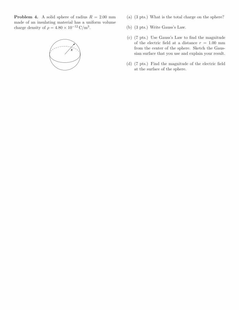
Problem 4. A solid sphere of radius R = 2.00 mmmade of an insulating material has a uniform volumecharge density of ρ = 4.80 × 10⁻¹² C/m3.
R
(a) (3 pts.) What is the total charge on the sphere?
(b) (3 pts.) Write Gauss’s Law.
(c) (7 pts.) Use Gauss’s Law to find the magnitudeof the electric field at a distance r = 1.00 mmfrom the center of the sphere. Sketch the Gaus-sian surface that you use and explain your result.
(d) (7 pts.) Find the magnitude of the electric fieldat the surface of the sphere.

Problem 5. Panel (a) shows a negative ion with massm = 1.50 × 10⁻²⁶ kg and charge Q = −2.00 × 10⁻¹⁹ Cmoving along the z axis away from eight identical pointcharges with q = 3.25 × 10⁻¹⁹ C. These eight chargesare fixed in the xy plane as shown in panel (b); alleight charges are the same distance b = 0.5 nm fromthe origin.
x
yq
q
q
q
q
q
bx
y
z
The charges are in the xy plane at thevertices of a regular octagon centeredat the origin. All charges are the samedistance (b) from the origin.
(a) PERSPECTIVE VIEW: (b) VIEW LOOKING DOWN z AXIS:
Q (v = v0 k)
b
(a) (7 pts.) Write an expression for the potential atan arbitrary point on the z axis due to the fixedcharge distribution in the xy plane. Give youranswer in terms of q, z, b, and standard physicalconstants. Hint: Use symmetry.
(b) (6 pts.) At the instant shown in the figure, thez coordinate of the negative ion is 1.2 nm, andits speed is v0 = 15.3 km/s. Find the potentialenergy, kinetic energy, and total energy of theion. Show all work and give numerical answers injoules.
(c) (7 pts.) The negative ion will slow down andreach a point z = z′ where its speed is zero. Showexplicitly the equation that must be solved to findz′, and then solve that equation for z′. Assumethat the particle is constrained to stay on the zaxis.

Physics 21Fall, 2010
Equation Sheet
speed of light in vacuo c 3.00 × 10⁸ m/sGravitational constant G 6.67 × 10⁻¹¹ N m2/kg2
Avogadro’s Number NA 6.02 × 10²³ mol−1
Boltzmann’s constant kB 1.38 × 10⁻²³ J/Kcharge on electron e 1.60 × 10⁻¹⁹ Cfree space permittivity ε0 8.85 × 10⁻¹² C2/(N m2)free space permeability µ0 4π × 10−7 T m/Agravitational acceleration g 9.807 m/s2
Planck’s constant h 6.626 × 10⁻³⁴ J sPlanck’s constant/(2π) h = h/2π 1.055 × 10⁻³⁴ J selectron rest mass me 9.11 × 10⁻³¹ kgproton rest mass mp 1.6726 × 10⁻²⁷ kgneutron rest mass mn 1.6749 × 10⁻²⁷ kgatomic mass unit u 1.6605 × 10⁻²⁷ kg1/(4πε0) k 8.99 × 10⁹ N m2/C2
F2 on1 =1
4πε0
q1q2(r1 − r2)
|r1 − r2|3F = qE
dE (at r) =1
4πε0
dQ (r − r′)
|r − r′|3E = −∇V
= −(
i∂V
∂x+ j
∂V
∂y+ k
∂V
∂z
)
Vf − Vi = − ∫ f
iE · dl
V =1
4πε0
Q
r; dV =
1
4πε0
dQ
|r − r′|uelec = 1
2ε0E
2, umag =1
2µ0B2
Work =∫
F · dl
Eline =1
2πε0
λ
r; Eplane =
σ
2ε0
E =Q
ε0A=
σ
ε0
for ‖ platecapacitor
Q=CV ; C =ε0KA
d=ε
A
d
Ucap = 12CV 2 = 1
2
Q2
C
Uind = 12LI2
V = IR R =ρL
A
P = IV P = I2R
R = mv⊥/(qB) circ. orbit
A × B =
∣∣∣∣∣∣i j k
Ax Ay Az
Bx By Bz
∣∣∣∣∣∣
ξi=Ci (series) or Ri (parallel):
1
ξeffective=
1
ξ1+
1
ξ2
ξi=Ci (parallel) or Ri (series):
ξeffective = ξ1 + ξ2
XR = R, XL = ωL, XC =1
ωCRC time constant = RC
LR time constant = L/R
Q(t) for RLC circuit
Q0 exp(−Rt/2L) cos ωt
ω2 =1
LC− R2
4L2
F=qv × B; dF=Idl × B
dB =µ0
4π
Idl × (r − r′)
|r − r′|3
long wire: B =µ0I
2πRcenter loop: B = µ0I/2R
I =dQ
dtI = −neAvd
Vs
Vp=
Ns
Np,
Is
Ip=
Np
Ns
χm =µ
µ0− 1
τ = µ × B µ = IA
solenoid B = µ0nI
solenoid L = µ0N2A/l
∮E · dA =
Q
ε0∮B · dA = 0
∮E · dl = − d
dt
∫B · dA
∮B · dl = µ0I + µ0ε0
d
dt
∫E · dA
sin(a ± b) = sin a cos b ± cos a sin b
sin(θ ± π2) = sin θ cos π
2± cos θ sin π
2
= ± cos θ
cos(a ± b) = cos a cos b ∓ sin a sin b
sin a + sin b = 2 cos(
a − b
2
)sin
(a + b
2
)
C = 2πr circumference of circleC = πd circumference of circleA = πr2 area of circleA = 4πr2 surface area of sphereV = 4
3πr3 volume of sphere
ax2 + bx + c = 0 ⇒x =
−b ±√b2 − 4ac
2a
∫du√
a2 + u2= ln
(u +
√a2 + u2
)∫
u du√a2 + u2
=√
a2 + u2
∫du
a2 + u2=
1
atan−1
(u
a
)∫
u du
a2 + u2= 1
2ln
(a2 + u2
)
∫du
(a2 + u2)3/2=
u
a2√
a2 + u2∫u du
(a2 + u2)3/2= − 1√
a2 + u2∫eau du =
1
aeau
∫ln u du = u ln u − u
∫un du =
1
n + 1un+1
∫du
a + bu=
1
bln(a + bu)
∫du
u= ln u
∫ 2π
0
cos2 θ dθ =
∫ 2π
0
sin2 θ dθ = π
v =√
T/ρ (T=tension)
v = (347.4 m/s)√
T/300
v = λf = ω/k
ω = 2πf k = 2π/λ
T = 1/f (T=period)
〈P 〉 = 12ρA2ω2v
∂ 2D
∂x2=
1
v2
∂ 2D
∂t2
S =1
µ0(E × B)
S = 12ε0cE
20 = 1
2
c
µ0B2
0
=E0B0
2µ0=
ErmsBrms
µ0
c = 1/√
ε0µ0
E × B ∝ v (plane wave)
∆x∆p >∼ h (h = h/2π)
λ = h/p (de Broglie)
− h2
2M
∂ 2ψ
∂x2= ih
∂ψ
∂t
KE = p2/(2M)
p = hk E = hω = hf
eiθ = cos θ + i sin θ
August 29, 2010

Physics 21Fall, 2010
Solution to Hour Exam #1
The graders for the problems were:1 Jones, 2 Faust, 3 Malenda, 4 and 5 BeelsFor questions about the grading, see the grader by Oct. 27.
Problem 1. Consider the following circuit:
2 Ω
I1
11 V
21 V
7 Ω3 Ω
I2 I3a b
c d
loop 1 loop 2
loop 3
(a) (13 pts.) Write Kirchhoff’s loop and junction (ornode) equations needed to determine the currentsI1, I2, and I3. Use the currents and their di-rections specified by the arrows in the diagram.You must write these equations as definedin Physics 21. You should have three equationsfor three unknowns. Draw clearly and labelon the diagram the loop used to determineeach loop equation.
(b) (3 pts.) Determine the currents I1, I2, and I3
(including the correct sign) by explicit solution ofthe equations you determined in part (a). Youmust show your work.
(c) (2 pts.) Use the currents you calculated in part(b) to find the potential difference Vd − Va be-tween the corner points labelled d and a on thediagram, using the path through corner point b.Show your work.
(d) (2 pts.) Repeat part (c), but take the paththrough corner point c. Show your work, includ-ing the potential change across the resistor andbattery separately. You should get the same valuefor Vd − Va that you found in part (c).

Problem 2. Two parallel plate capacitors are con-nected to a battery and a resistor as shown in the cir-cuit. For the first capacitor, C1 = 1.24 nF; for theother, C2 = 3.72 nF. The voltage of the battery isV0 = 12 volts, and the resistance R = 3500 Ω.
V0
R
S(a)
V0
R
S(b)
Q1 Q2C1 C2
C1 C2
(a) (8 pts.) Assuming that the circuit in panel (a) hasbeen connected for a very long time, what are thecharges Q1 and Q2 on each capacitor? What isthe energy stored in each capacitor? Give numer-ical answers.
(b) (6 pts.) At time t = 0 the switch S is flippedso that the circuit appears as shown in panel (b),and the capacitors discharge through the resistor.What is the time constant of the circuit?
(c) (2 pts.) What is the current that starts to flowin the circuit of panel (b) just after t = 0?
(d) (4 pts.) At what time t′ will the total charge onthe two capacitors diminish to 60% of its initialvalue? What fraction of the initial energy willremain at time t = t′?

Problem 3. For this problem you are to find the elec-tric field at the point P on the y axis due to the chargedistribution on the x axis. A total charge of 3Q is uni-formly spread out from x = −b to x = +2b.
-b x' 2b
dQ
P = (0,y,0)
r - r'
(a) (3 pts.) What is the linear charge density λ onthe rod?
(b) (3 pts.) On the diagram shown, draw the vector(r − r′) (as defined in class) from the charge dQon the rod at x = x′ to the point P on the y axis.Write an expression for the vector (r − r′) thatindicates its components.
(c) (7 pts.) Write an expression for the electric fielddE at the point P due to the element of chargedQ at the point x′ on the rod. The expressionfor dE should be in terms of Q, b, dx′, x′, y, andNOT dQ.
(d) (7 pts.) Integrate to find ONLY THE y COM-PONENT of the electric field E at the point Pdue to the rod. Your answer should be in termsof Q, b, and y.

Problem 4. A solid sphere of radius R = 2.00 mmmade of an insulating material has a uniform volumecharge density of ρ = 4.80 × 10⁻¹² C/m3.
RR/2
(a) (3 pts.) What is the total charge on the sphere?
(b) (3 pts.) Write Gauss’s Law.
(c) (7 pts.) Use Gauss’s Law to find the magnitudeof the electric field at a distance r = 1.00 mmfrom the center of the sphere. Sketch the Gaus-sian surface that you use and explain your result.
(d) (7 pts.) Find the magnitude of the electric fieldat the surface of the sphere.

Problem 5. Panel (a) shows a negative ion with massm = 1.50 × 10⁻²⁶ kg and charge Q = −2.00 × 10⁻¹⁹ Cmoving along the z axis away from eight identical pointcharges with q = 3.25 × 10⁻¹⁹ C. These eight chargesare fixed in the xy plane as shown in panel (b); alleight charges are the same distance b = 0.5 nm fromthe origin.
x
yq
q
q
q
q
q
bx
y
z
The charges are in the xy plane at thevertices of a regular octagon centeredat the origin. All charges are the samedistance (b) from the origin.
(a) PERSPECTIVE VIEW: (b) VIEW LOOKING DOWN z AXIS:
Q (v = v0 k)
b
(a) (7 pts.) Write an expression for the potential atan arbitrary point on the z axis due to the fixedcharge distribution in the xy plane. Give youranswer in terms of q, z, b, and standard physicalconstants. Hint: Use symmetry.
(b) (6 pts.) At the instant shown in the figure, thez coordinate of the negative ion is 1.2 nm, andits speed is v0 = 15.3 km/s. Find the potentialenergy, kinetic energy, and total energy of theion. Show all work and give numerical answers injoules.
(c) (7 pts.) The negative ion will slow down andreach a point z = z′ where its speed is zero. Showexplicitly the equation that must be solved to findz′, and then solve that equation for z′. Assumethat the particle is constrained to stay on the zaxis.

Physics 21Fall, 2011
Solution to Hour Exam #1
The graders for the problems were:1 Tupa, 2 Faust, 3 Beels, 4 Malenda, 5 GluecksteinFor questions about the grading, see the grader by Oct. 26.
Problem 1. Consider the following circuit:
2 Ω
I18 V
12 V
6 Ω7 Ω
I2 I3a b
c d
loop 1 loop 2
(a) (13 pts.) Write Kirchhoff’s loop and junction (ornode) equations needed to determine the currentsI1, I2, and I3. Use the currents and their di-rections specified by the arrows in the diagram.You must write these equations as definedin Physics 21. You should have three equationsfor three unknowns. Draw clearly and labelon the diagram the loop used to determineeach loop equation.
(b) (3 pts.) Determine the currents I1, I2, and I3 (in-cluding the correct sign) by explicit solution, byhand, of the equations you determined in part (a).You must show your work.
(c) (2 pts.) Use the currents you calculated in part(b) to find the potential difference Vc−Vb betweenthe corner points labelled c and b on the diagram,using the path through corner point a. Show yourwork, including the potential change across anycircuit elements on this path.
(d) (2 pts.) Repeat part (c), but take the paththrough corner point d. Show your work, includ-ing the potential change across any circuit ele-ments on this path. You should get the samevalue for Vc − Vb that you found in part (c).

Problem 2. A point charge q is located at the centerof a spherical cavity of radius rcav inside an insulating,spherical charged solid:
rcav
r
q
S
For this problem, q = −6.1 µC, rcav = 3.3 cm, thecharge density in the solid is ρ = 1.5 × 10⁻³ C/m3,and you are to use Gauss’ Law to calculate the electricfield inside the solid at a distance r = 5.6 cm from thecenter of the cavity.
(a) (3 pts.) Write Gauss’ Law.
(b) (3 pts.) What is the shape and location of theGaussian surface S that you will use? Draw andlabel S neatly on the diagram to the left.
(c) (6 pts.) What is the total charge enclosed by S?
(d) (6 pts.) Find the magnitude of the electric fieldat distance r = 5.6 cm from the point charge q.
(e) (2 pts.) What is the direction of the electric field?Justify your answer.
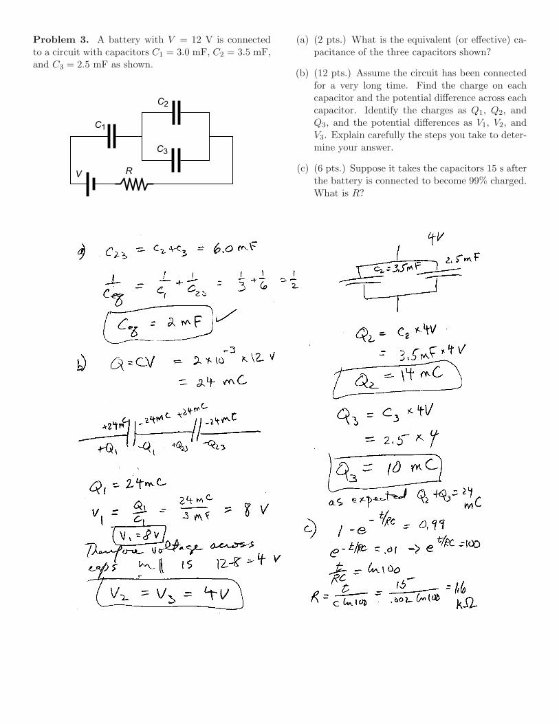
Problem 3. A battery with V = 12 V is connectedto a circuit with capacitors C1 = 3.0 mF, C2 = 3.5 mF,and C3 = 2.5 mF as shown.
C1
C2
C3
V R
(a) (2 pts.) What is the equivalent (or effective) ca-pacitance of the three capacitors shown?
(b) (12 pts.) Assume the circuit has been connectedfor a very long time. Find the charge on eachcapacitor and the potential difference across eachcapacitor. Identify the charges as Q1, Q2, andQ3, and the potential differences as V1, V2, andV3. Explain carefully the steps you take to deter-mine your answer.
(c) (6 pts.) Suppose it takes the capacitors 15 s afterthe battery is connected to become 99% charged.What is R?
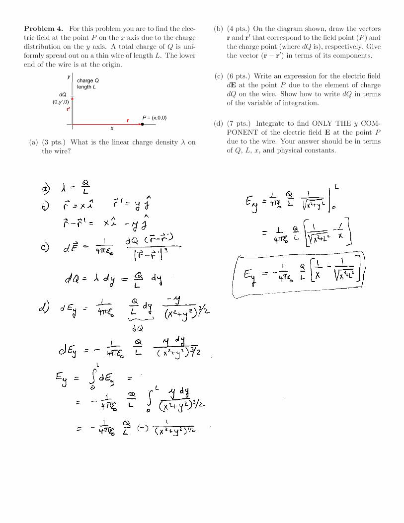
Problem 4. For this problem you are to find the elec-tric field at the point P on the x axis due to the chargedistribution on the y axis. A total charge of Q is uni-formly spread out on a thin wire of length L. The lowerend of the wire is at the origin.
x
y
dQ
P = (x,0,0)
charge Qlength L
(0,y',0)
r
r'
(a) (3 pts.) What is the linear charge density λ onthe wire?
(b) (4 pts.) On the diagram shown, draw the vectorsr and r′ that correspond to the field point (P ) andthe charge point (where dQ is), respectively. Givethe vector (r − r′) in terms of its components.
(c) (6 pts.) Write an expression for the electric fielddE at the point P due to the element of chargedQ on the wire. Show how to write dQ in termsof the variable of integration.
(d) (7 pts.) Integrate to find ONLY THE y COM-PONENT of the electric field E at the point Pdue to the wire. Your answer should be in termsof Q, L, x, and physical constants.
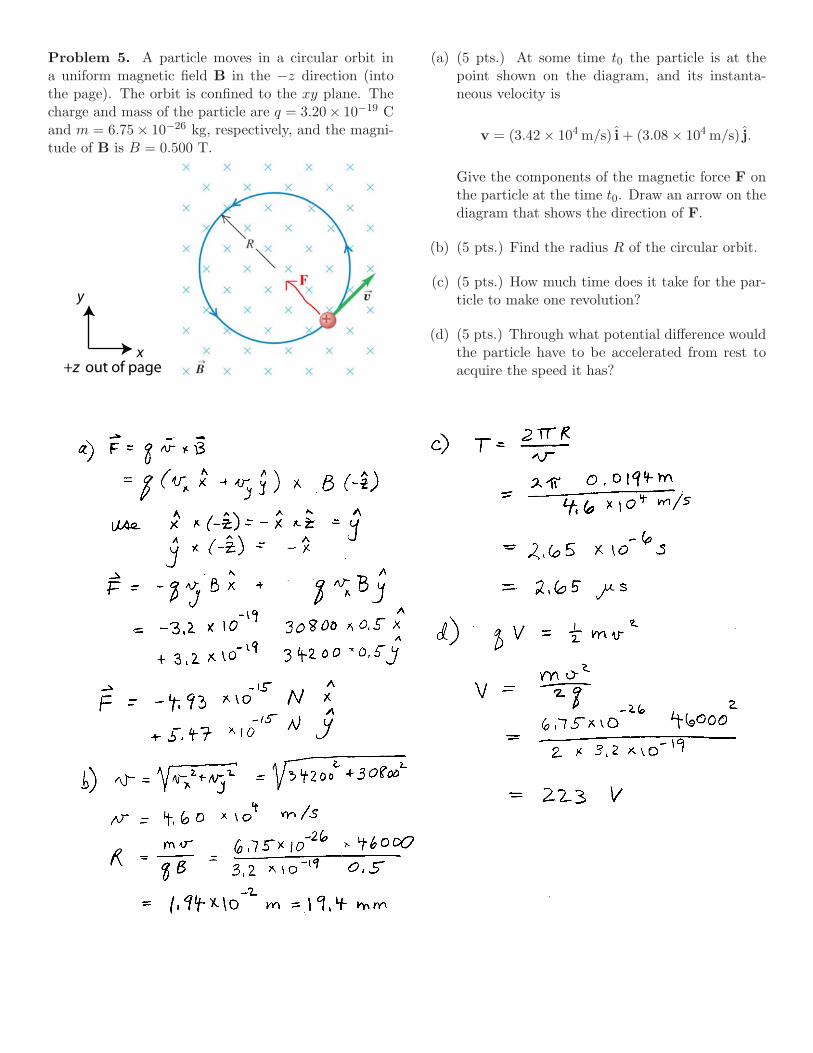
Problem 5. A particle moves in a circular orbit ina uniform magnetic field B in the −z direction (intothe page). The orbit is confined to the xy plane. Thecharge and mass of the particle are q = 3.20× 10⁻¹⁹ Cand m = 6.75 × 10⁻²⁶ kg, respectively, and the magni-tude of B is B = 0.500 T.
x
y
+z out of page
(a) (5 pts.) At some time t0 the particle is at thepoint shown on the diagram, and its instanta-neous velocity is
v = (3.42 × 10⁴ m/s) i + (3.08 × 10⁴ m/s) j.
Give the components of the magnetic force F onthe particle at the time t0. Draw an arrow on thediagram that shows the direction of F.
(b) (5 pts.) Find the radius R of the circular orbit.
(c) (5 pts.) How much time does it take for the par-ticle to make one revolution?
(d) (5 pts.) Through what potential difference wouldthe particle have to be accelerated from rest toacquire the speed it has?

Physics 21Fall, 2011
Information about Exam 2
Second Hour Exam: There will be an exam on Wednes-day, November 9, 2011 at 4:10 pm. The exam will be closedbook and closed notes. Any physical constants and integralsyou need will be given on the exam. The equation sheetposted on the course web site will be included on the exam.Here are the room assignments:
Chandler Ullman 248 Glueckstein (all), Beels (9 a.m.)and all extra time students
Packard 466 Malenda (all), Faust (all)Packard 416 Tupa (all), Beels (10 a.m.)
Use of Calculators and Other Electronic Devices:You should bring a calculator. Cell phones, music playersand headphones are prohibited and must not even be visibleduring the exam.
Units: In order to receive full credit, all numerical answersmust include the correct units. Be careful about this point,because the online homework system usually provides theunits for you. You should be familiar with the commonprefixes femto through giga.
Practice Exam and Review Session: A practice exam isavailable from the class web site. Some of the problems onthe practice exam are taken from previous exams in Physics21. If you can work the problems on the practice exam withinthe time alloted, you should be well prepared for the realexam. The solution to the practice exam will be postedon the web and also discussed in a review session Tuesday,November 8 at 7:10 pm in LL270. Other review sessions mayalso be held; check the class website for the schedule.
Coverage: The exam will cover material starting with ourinitial discussion of magnetism (the beginning of Chapter27). There is some overlap with the material on the magneticfield covered on the first exam. Specifically, the exam willcover the lectures numbered 9–18 inclusive and homeworks10–20 inclusive, as well as all the reading assignments inChapters 27–31 of the text, except for §31.6 on transformers.Problem 31-37 on hw20 is about transformers and won’t beon the test.
The exam will emphasize the material covered in lecture,recitation or homework. The following is a list of topicsand questions you should be familiar with. This list is notnecessarily complete but is representative.
• Know the common prefixes femto through giga.
• In a magnetic field, what is the force on a movingcharged particle? What is the force on a current?
• Be able to use the right hand rule to get the directionof magnetic fields or of cross products. Know how toevaluate cross products.
• What does the magnetic field of a current loop look like?
• Be able to use the Biot-Savart Law.
• Know why a charged particle can exhibit circular orspiral motion in a magnetic field.
• How does a velocity selector work?
• What is the magnetic dipole moment of a current loop?What are the forces and torques on a current loop in auniform magnetic field?
• How does a simple dc motor work?
• What is Faraday’s Law? What is Lenz’s Law? Knowhow to apply them.
• What are the magnetic and electric flux? Know how toevaluate them.
• What is hysteresis?
• What is ferromagnetism? diamagnetism? paramag-netism? What is a magnetic domain?
• What is mutual inductance? What is self inductance?Why does a solenoid exhibit self inductance?
• What is Ampere’s Law (final form)? Know how to useit. What is the displacement current?
• What do “transient” and “steady state” mean with re-spect to dc and ac circuits?
• Know how to analyze the transient behavior of an LRcircuit. What do the exponential functions exp(−t/τ)and 1 − exp(−t/τ) look like? What is τ?
• What is the energy stored in a magnetic field?
• Why can there be oscillations in an LC circuit? Whatis the resonant frequency? Be able to track where theenergy is during the oscillations. What happens if youadd a resistor to the circuit?
• What are Maxwell’s Equations?
• Know how to use phasor diagrams. You should knowthe phase relations between current and voltage in theprototypical ac circuits with only R, L, or C elementsbesides the power supply. What does it mean if, forexample, the voltage leads the current across a circuitelement? What is the resonant frequency of an RLCcircuit with an ac power supply?
• What is the power delivered to an ac circuit?
• In an ac circuit, what is the relation between peak valuesand rms values?
November 3, 2011

Physics 21Fall, 2010
Hour Exam #2
1 2 3 4 5 Total Name:
Recitation Time Recitation Leader November 10, 2010
This exam is closed notes and closed book. You must show enough work on each problem to convince the graderyou understand how to solve the problem. You may use a calculator, but show every number that you useto get numerical results. The penalty for arithmetic errors is small if the grader can tell what youintended to do. Give units for all final answers. There is an equation sheet on the last page. All problems count20 points.
Problem 1. For the following circuit:
(a) (8 pts.) If R = 22.0 Ω, L = 25.0 mH, C =10.0 µF, and ω = 800.0 rad/s, draw a phasor di-agram that is approximately to scale. Include aphasor for the ac voltage V , and give the lengthof each phasor. Draw a mark on your diagram toindicate the phase angle φ.
(b) (3 pts.) Evaluate the peak value of the current Iif the peak voltage supplied by the power supplyis 8.00 V. Show all work.
(c) (3 pts.) Evaluate the phase angle φ. Does thevoltage lead or lag the current?
(d) (3 pts.) What is the average power delivered tothe circuit by the power supply?
(e) (3 pts.) What is the time interval between a max-imum in voltage across the inductor and the nextmaximum in voltage across the power supply?

Problem 2. A small circular wire loop is inside alarger loop that is connected to the circuit as shown.The values of the circuit elements are L = 15.0 H,R = 30.0 Ω, and V0 = 12.0 V. At t = 0 the switchS is closed to complete the circuit.
(a) (5 pts.) What is the time constant of this circuit?
(b) (5 pts.) What is the current in the large loop along time after the switch has been closed?
(c) (5 pts.) Using the box printed below, carefullydraw a plot that shows the current i(t) in thelarge loop as a function of time, starting at t = 0.Fill in numerical values in seconds and amperesfor several tic marks on the horizontal and verti-cal axes to set reasonable scales for these axes.
(d) (3 pts.) Is the direction of the induced current inthe small circular wire loop soon after the switchis closed clockwise or counterclockwise?
(e) (2 pts.) Now this experiment is repeated. Thelarge loop remains the same, but the small wireinner loop is replaced with one that has half thediameter. When the switch S is closed, wouldthe induced emf in the wire loop be smaller orlarger than it was in the first experiment? Brieflyexplain your answer.
Draw the graph for part (c) in this box:

Problem 3. A metal bar moves to the left with con-stant speed v = 8.00 m/s through a uniform magneticfield of magnitude B = 1.5 T as shown in the diagram.The distance between the rails is 0.5 m. The only resis-tance in the circuit may be taken to be the resistanceR = 24 Ω shown.
(a) (4 pts.) Give Faraday’s Law (as an equation).
(b) (4 pts.) What is the magnitude of the emf in-duced in the circuit (before the metal bar hitsthe resistor)?
(c) (4 pts.) Is the direction of the current induced inthe circuit clockwise or counterclockwise?
(d) (4 pts.) Calculate the current through the resis-tor.
(e) (4 pts.) Because of the induced current in thecircuit, the magnetic field exerts a force on themoving metal bar. Find the magnitude and di-rection of that force.

Problem 4. The long wire shown in the diagram liesin the xy plane and carries a current I = 0.500 A. Thepositive z axis points out of the page.
For this problem you are to find the contribution dBto the magnetic field at several points due to the darksegment dl of the wire centered at the origin. The darksegment has a length 3.0 mm and makes an angle of60 with the x axis.
(a) (6 pts.) Write a vector expression for the currentelement I dl. (Use the unit vectors i and j.)
(b) (7 pts.) Find dB at x = 0, y = 0, z = 3.0 m
(c) (7 pts.) Find dB at x = 4.2 m, y = 7.3 m, z = 0

Problem 5. For the following circuit, C = 25µF andL = 32 mH. Just before the switch is closed at timet = 0, the charge on the capacitor is Q0 = 1.25 mC.
(a) (4 pts.) What is the total energy stored in thecircuit before the switch is closed?
(b) (3 pts.) Give the equation that relates the cur-rent i shown on the diagram and the charge q onthe capacitor. (i gives the direction of positivecurrent flow just after the switch is closed.)
(c) (6 pts.) Write the loop equation for this circuitand convert it to a differential equation for thecharge on the capacitor, q(t). Verify that the so-lution to the differential equation is
q(t) = Q0 cos ωt.
(d) (4 pts.) Calculate the value of ω for this circuit.
(e) (3 pts.) What is the energy stored in the electricfield of the capacitor at an instant when the mag-nitude of the magnetic field in the inductor is60% of its maximum value?

Physics 21Fall, 2010
Equation Sheet
speed of light in vacuo c 3.00 × 10⁸ m/sGravitational constant G 6.67 × 10⁻¹¹ N m2/kg2
Avogadro’s Number NA 6.02 × 10²³ mol−1
Boltzmann’s constant kB 1.38 × 10⁻²³ J/Kcharge on electron e 1.60 × 10⁻¹⁹ Cfree space permittivity ε0 8.85 × 10⁻¹² C2/(N m2)free space permeability µ0 4π × 10−7 T m/Agravitational acceleration g 9.807 m/s2
Planck’s constant h 6.626 × 10⁻³⁴ J sPlanck’s constant/(2π) h = h/2π 1.055 × 10⁻³⁴ J selectron rest mass me 9.11 × 10⁻³¹ kgproton rest mass mp 1.6726 × 10⁻²⁷ kgneutron rest mass mn 1.6749 × 10⁻²⁷ kgatomic mass unit u 1.6605 × 10⁻²⁷ kg1/(4πε0) k 8.99 × 10⁹ N m2/C2
F2 on1 =1
4πε0
q1q2(r1 − r2)
|r1 − r2|3F = qE
dE (at r) =1
4πε0
dQ (r − r′)
|r − r′|3E = −∇V
= −(
i∂V
∂x+ j
∂V
∂y+ k
∂V
∂z
)
Vf − Vi = − ∫ f
iE · dl
V =1
4πε0
Q
r; dV =
1
4πε0
dQ
|r − r′|uelec = 1
2ε0E
2, umag =1
2µ0B2
Work =∫
F · dl
Eline =1
2πε0
λ
r; Eplane =
σ
2ε0
E =Q
ε0A=
σ
ε0
for ‖ platecapacitor
Q=CV ; C =ε0KA
d=ε
A
d
Ucap = 12CV 2 = 1
2
Q2
C
Uind = 12LI2
V = IR R =ρL
A
P = IV P = I2R
R = mv⊥/(qB) circ. orbit
A × B =
∣∣∣∣∣∣i j k
Ax Ay Az
Bx By Bz
∣∣∣∣∣∣
ξi=Ci (series) or Ri (parallel):
1
ξeffective=
1
ξ1+
1
ξ2
ξi=Ci (parallel) or Ri (series):
ξeffective = ξ1 + ξ2
XR = R, XL = ωL, XC =1
ωCRC time constant = RC
LR time constant = L/R
Q(t) for RLC circuit
Q0 exp(−Rt/2L) cos ωt
ω2 =1
LC− R2
4L2
F=qv × B; dF=Idl × B
dB =µ0
4π
Idl × (r − r′)
|r − r′|3
long wire: B =µ0I
2πRcenter loop: B = µ0I/2R
I =dQ
dtI = −neAvd
Vs
Vp=
Ns
Np,
Is
Ip=
Np
Ns
χm =µ
µ0− 1
τ = µ × B µ = IA
solenoid B = µ0nI
solenoid L = µ0N2A/l
∮E · dA =
Q
ε0∮B · dA = 0
∮E · dl = − d
dt
∫B · dA
∮B · dl = µ0I + µ0ε0
d
dt
∫E · dA
sin(a ± b) = sin a cos b ± cos a sin b
sin(θ ± π2) = sin θ cos π
2± cos θ sin π
2
= ± cos θ
cos(a ± b) = cos a cos b ∓ sin a sin b
sin a + sin b = 2 cos(
a − b
2
)sin
(a + b
2
)
C = 2πr circumference of circleC = πd circumference of circleA = πr2 area of circleA = 4πr2 surface area of sphereV = 4
3πr3 volume of sphere
ax2 + bx + c = 0 ⇒x =
−b ±√b2 − 4ac
2a
∫du√
a2 + u2= ln
(u +
√a2 + u2
)∫
u du√a2 + u2
=√
a2 + u2
∫du
a2 + u2=
1
atan−1
(u
a
)∫
u du
a2 + u2= 1
2ln
(a2 + u2
)
∫du
(a2 + u2)3/2=
u
a2√
a2 + u2∫u du
(a2 + u2)3/2= − 1√
a2 + u2∫eau du =
1
aeau
∫ln u du = u ln u − u
∫un du =
1
n + 1un+1
∫du
a + bu=
1
bln(a + bu)
∫du
u= ln u
∫ 2π
0
cos2 θ dθ =
∫ 2π
0
sin2 θ dθ = π
v =√
T/ρ (T=tension)
v = (347.4 m/s)√
T/300
v = λf = ω/k
ω = 2πf k = 2π/λ
T = 1/f (T=period)
〈P 〉 = 12ρA2ω2v
∂ 2D
∂x2=
1
v2
∂ 2D
∂t2
S =1
µ0(E × B)
S = 12ε0cE
20 = 1
2
c
µ0B2
0
=E0B0
2µ0=
ErmsBrms
µ0
c = 1/√
ε0µ0
E × B ∝ v (plane wave)
∆x∆p >∼ h (h = h/2π)
λ = h/p (de Broglie)
− h2
2M
∂ 2ψ
∂x2= ih
∂ψ
∂t
KE = p2/(2M)
p = hk E = hω = hf
eiθ = cos θ + i sin θ
August 29, 2010

Physics 21Fall, 2010
Solution to Hour Exam #2
If you want to discuss the grading, you must speak with the grader by Dec. 8.1: Beels 2: Jones 3: Faust 4: Beels 5: Glueckstein
Problem 1. For the following circuit:
(a) (8 pts.) If R = 22.0 Ω, L = 25.0 mH, C =10.0 µF, and ω = 800.0 rad/s, draw a phasor di-agram that is approximately to scale. Include aphasor for the ac voltage V , and give the lengthof each phasor. Draw a mark on your diagram toindicate the phase angle φ.
(b) (3 pts.) Evaluate the peak value of the current Iif the peak voltage supplied by the power supplyis 8.00 V. Show all work.
(c) (3 pts.) Evaluate the phase angle φ. Does thevoltage lead or lag the current?
(d) (3 pts.) What is the average power delivered tothe circuit by the power supply?
(e) (3 pts.) What is the time interval between a max-imum in voltage across the inductor and the nextmaximum in voltage across the power supply?

Problem 2. A small circular wire loop is inside alarger loop that is connected to the circuit as shown.The values of the circuit elements are L = 15.0 H,R = 30.0 Ω, and V0 = 12.0 V. At t = 0 the switchS is closed to complete the circuit.
(a) (5 pts.) What is the time constant of this circuit?
(b) (5 pts.) What is the current in the large loop along time after the switch has been closed?
(c) (5 pts.) Using the box printed below, carefullydraw a plot that shows the current i(t) in thelarge loop as a function of time, starting at t = 0.Fill in numerical values in seconds and amperesfor several tic marks on the horizontal and verti-cal axes to set reasonable scales for these axes.
(d) (3 pts.) Is the direction of the induced current inthe small circular wire loop soon after the switchis closed clockwise or counterclockwise?
(e) (2 pts.) Now this experiment is repeated. Thelarge loop remains the same, but the small wireinner loop is replaced with one that has half thediameter. When the switch S is closed, wouldthe induced emf in the wire loop be smaller orlarger than it was in the first experiment? Brieflyexplain your answer.
Draw the graph for part (c) in this box:

Problem 3. A metal bar moves to the left with con-stant speed v = 8.00 m/s through a uniform magneticfield of magnitude B = 1.5 T as shown in the diagram.The distance between the rails is 0.5 m. The only resis-tance in the circuit may be taken to be the resistanceR = 24 Ω shown.
(a) (4 pts.) Give Faraday’s Law (as an equation).
(b) (4 pts.) What is the magnitude of the emf in-duced in the circuit (before the metal bar hitsthe resistor)?
(c) (4 pts.) Is the direction of the current induced inthe circuit clockwise or counterclockwise?
(d) (4 pts.) Calculate the current through the resis-tor.
(e) (4 pts.) Because of the induced current in thecircuit, the magnetic field exerts a force on themoving metal bar. Find the magnitude and di-rection of that force.

Problem 4. The long wire shown in the diagram liesin the xy plane and carries a current I = 0.500 A. Thepositive z axis points out of the page.
For this problem you are to find the contribution dBto the magnetic field at several points due to the darksegment dl of the wire centered at the origin. The darksegment has a length 3.0 mm and makes an angle of60 with the x axis.
(a) (6 pts.) Write a vector expression for the currentelement I dl. (Use the unit vectors i and j.)
(b) (7 pts.) Find dB at x = 0, y = 0, z = 3.0 m
(c) (7 pts.) Find dB at x = 4.2 m, y = 7.3 m, z = 0
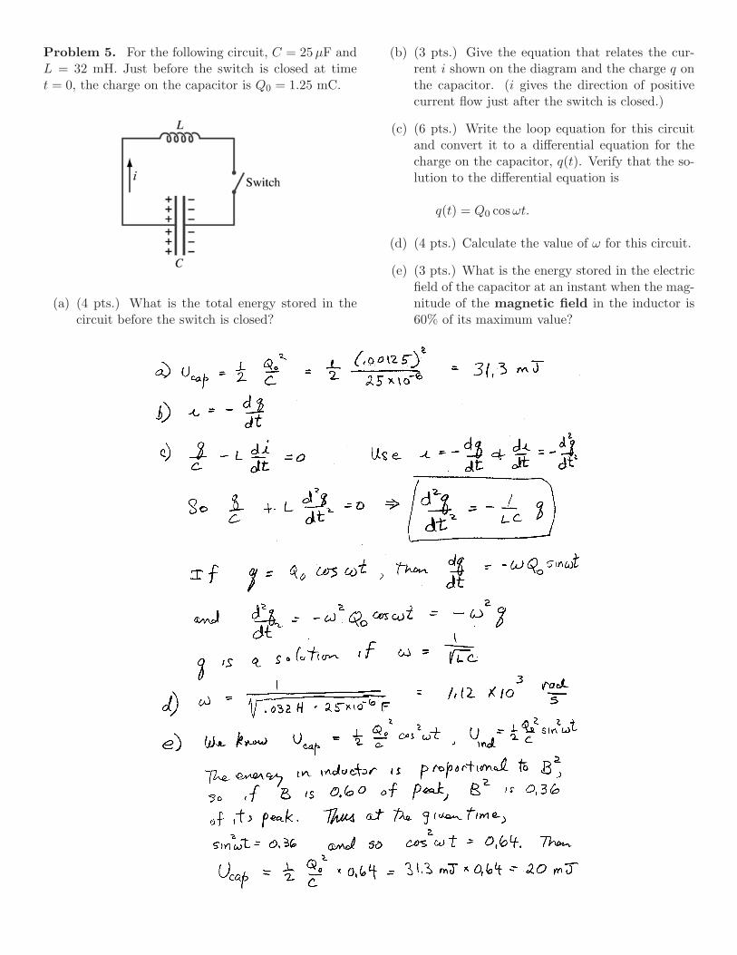
Problem 5. For the following circuit, C = 25µF andL = 32 mH. Just before the switch is closed at timet = 0, the charge on the capacitor is Q0 = 1.25 mC.
(a) (4 pts.) What is the total energy stored in thecircuit before the switch is closed?
(b) (3 pts.) Give the equation that relates the cur-rent i shown on the diagram and the charge q onthe capacitor. (i gives the direction of positivecurrent flow just after the switch is closed.)
(c) (6 pts.) Write the loop equation for this circuitand convert it to a differential equation for thecharge on the capacitor, q(t). Verify that the so-lution to the differential equation is
q(t) = Q0 cos ωt.
(d) (4 pts.) Calculate the value of ω for this circuit.
(e) (3 pts.) What is the energy stored in the electricfield of the capacitor at an instant when the mag-nitude of the magnetic field in the inductor is60% of its maximum value?


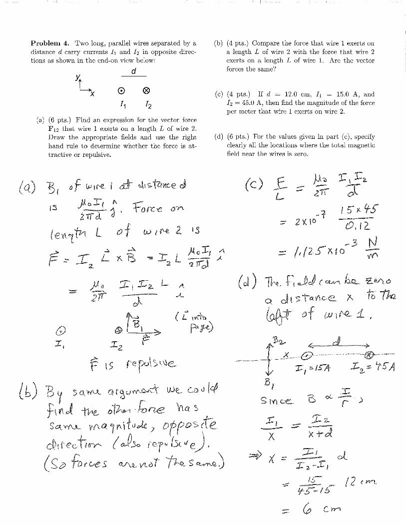
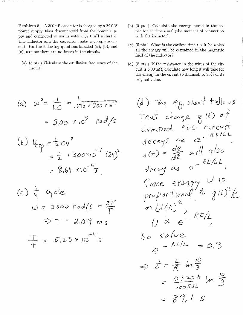

Physics 21Fall, 2011
Information about Final
Final Exam: The final exam will be Thursday, December15, 2011 from 7:10–10:10 pm. Almost everyone will be inPA 101; extra time students will be in LL221 and will start90 minutes early, at 5:30 pm. The exam will be closed bookand closed notes. The equation sheet and the handout onoptics (now posted on the course web site) will be includedwith the exam. Any physical constants and integrals youwill need will be given on the equation sheet.
Practice Questions: Representative questions on wavesand optics taken from previous exams in Physics 21 will beposted on the class web site. The two previous hour ex-ams and the associated practice exams provide representa-tive questions on electricity and magnetism. The solution tothe practice questions will be posted on the web.
Use of Calculators: You should bring a calculator. Ingeneral, however, setting up the problems and demonstratingthe correct strategy for solving them are worth more thandoing the arithmetic to get a numerical result. If you areasked to solve simultaneous algebraic equations, you mustsolve them by hand and show the solution to receive fullcredit.
Physics 19: The Physics 19 exam will consist of selectedproblems from the full Physics 21 exam. Physics 19 studentsmay take the full three hours to work the exam.
Coverage: The exam will cover all the material presentedthis semester. About 50% of the exam will be on electricityand magnetism and about 50% on waves and optics. Theemphasis will be on the material covered in lecture, recita-tion or homework. Some questions may come from materialpresented only in the lectures. There may be some short-answer questions, that is, you might be asked for a shortdefinition or an example. You will not be asked to solve dif-ferential equations, but you may be asked to verify that agiven function satisfies a differential equation.
You should be familiar with all the topics and questionslisted on the study guides for Hour Exams #1 and #2, aswell as with the items listed below that cover optics. Thelist is not necessarily complete but is representative.
• What is the Poynting vector? Know how to use it todescribe the transport of energy by an E&M wave.
• What is the difference between geometric and physicaloptics? What is the essential assumption of geometricoptics?
• What is the law of reflection (for a mirror)?
• Know how to use Snell’s Law.
• What is the paraxial approximation?
• Be able to draw ray diagams for mirrors and lenses usingthe notes handed out. Be able to draw a ray diagram fora magnifying glass or a telescope. Be able to analyize atwo-lens system algebraically.
• What is refraction? What is the index of refraction?
• What is disperson?
• Know the sign conventions for converging and diverg-ing lenses. Know how to use the lensmaker’s equation,including the sign conventions for the radii of curvature.
• How can you describe the path of a light ray using theprinciple of least time?
• Why is the case of parallel light rays important for alens or mirror?
• What is total internal reflection? What is the criticalangle?
• What makes a rainbow?
• What is the mathematical form of a traveling planewave?
• Know how to determine where the sound from twospeakers will interfere constructively or destructively.How does your analysis depend on whether the speakersare in phase or out of phase?
• What is chromatic aberration?
• What is an achromatic doublet?
• Be able to give examples of and explain phenomena in-cluded under the heading of diffraction and interference.What is a diffraction grating?
• Be able to sketch the interference pattern for the two slitexperiment if you are given the width and separation ofthe slits. What are missing orders and why do theyoccur?
• What are the approximate wavelengths of visible light?
• What is Huygens’ principle?
• What is the f -number of a lens?
• What is the difference between a real and a virtual im-age?
• What is the difference between discrete and continuousspectra? Be able to give an example of each.
• What limits the ability of a telescope to resolve twoclosely spaced binary stars? What is the Rayleigh cri-terion?
• What determines the polarization of an E&M wave?What is the relation between E and B and the velocityof the wave?
• What does a polarizing filter do?
December 9, 2011

Physics 21Fall, 2011
Practice Questions on Optics
Some of these questions on optics have been adapted from questions on the Physics 21 final given at the end ofthe spring semester of 2004. Try to work them using only the equation sheet and the notes on optics that will beprovided with the final.
Problem 1. Consider the polarizers in this problemas “perfect.” After passing through the first polarizer,the electric field of a light wave is (in SI units)
E = E0 cos[6.0 × 10¹⁵t − 2.0 × 10⁷x]j,
with E0 = 2.0 × 10⁴ V/m.
(a) What are the frequency and wavelength of thiswave?
(b) A second polarizer is oriented at 60 to the first.What is the magnitude and direction of the elec-tric field after passing through this second polar-izer?
60O
z
y
(c) A third polarizer is oriented in the z direction.What is the magnitude and direction of the elec-tric field after passing through the third polar-izer?
Problem 2. Two slits that are d = 2.0 × 10⁻⁴ mapart are illuminated with monochromatic light with awavelength of 600 nm.
L
(a) What is the angular separation θ between the cen-tral fringe and the next bright fringe?
(b) What is the spacing (in meters) between the brightfringes if the screen is L = 3.0 m from the slits?
Problem 3. A diverging lens with a focal length f =−0.06 m is 0.14 m from an object of height 0.02 m.
(a) Algebraically determine the location and the heightof the image.
(b) Determine the location and the height of the im-age using a ray diagram.
(c) Is the image real or virtual?
Problem 4. At noon on the first day of spring, thesun is directly overhead at a point on the equator; i.e.,the suns shines perpendicularly to the earth’s surfaceat that point. Let z be the direction straight down.Assume the electric and magnetic fields of this waveare (in SI units)
E(z, t) = E0 cos[2π
(5.0 × 10¹⁴ t − z
6.0 × 10⁻⁷
)]i
B(z, t) = B0 cos[2π
(5.0 × 10¹⁴ t − z
6.0 × 10⁻⁷
)]j
(a) What are the frequency, wavelength and velocityof this wave?
(b) If E0 = 1000 V/m, what is the average intensity(power/meter2) of this sunshine?
Problem 5. Two stars 10 light years away are barelyresolved by a 90 cm (mirror diameter) telescope. Howfar apart are the stars? Assume λ = 550 nm and thatthe resolution is limited by diffraction.

Physics 21Fall, 2011
Solution to Practice Questions
Some of these questions on optics have been adapted from questions on the Physics 21 final given at the end ofthe spring semester of 2004. Try to work them using only the equation sheet and the notes on optics that will beprovided with the final.
Problem 1. Consider the polarizers in this problemas “perfect.” After passing through the first polarizer,the electric field of a light wave is (in SI units)
E = E0 cos[6.0 × 10¹⁵t − 2.0 × 10⁷x]j,
with E0 = 2.0 × 10⁴ V/m.
(a) What are the frequency and wavelength of thiswave?
ω = 2πf = 6.0 × 10¹⁵ ⇒ f = 9.5 × 10¹⁴ Hzk = 2π/λ = 2.0 × 10⁷ ⇒ λ = 3.1 × 10⁻⁷ m
(b) A second polarizer is oriented at 60 to the first.What is the magnitude and direction of the elec-tric field after passing through this second polar-izer?
z
y
30O
60O
E0
E1
E2
The projection of E0 on the axis of the secondpolarizer is E1 = E0 cos 60 = 1 × 10⁴ V/m.
(c) A third polarizer is oriented in the z direction.What is the magnitude and direction of the elec-tric field after passing through the third polar-izer?
The projection of E1 on the axis of the third po-larizer is E2 = E1 cos 30 = 8.7 × 10³ V/m.
Problem 2. Two slits that are d = 2.0 × 10⁻⁴ mapart are illuminated with monochromatic light with awavelength of 600 nm.
L
(a) What is the angular separation θ between the cen-tral fringe and the next bright fringe?
The angular splitting (in radians) is given by
∆θ =λ
d=
600 × 10−9
2 × 10−4= 0.003
Note that this angular splitting is small enoughthat the small angle approximations used are jus-tified.
(b) What is the spacing (in meters) between the brightfringes if the screen is L = 3.0 m from the slits?
The spacing in meters is L∆θ = 3.0 m × 0.003 =0.009 m = 9 mm.

Problem 3. A diverging lens with a focal length f =−0.06 m is 0.14 m from an object of height 0.02 m.
(a) Algebraically determine the location and the heightof the image.
Let’s work the problem in cm. We have do = 14and f = −6. The lens equation gives
1di
=1f− 1
do=
1−6
− 114
=1
−4.2
So the image is 4.2 cm in front of the lens. Theheight is
hi =4.214
× 2 = 0.6 cm
(b) Determine the location and the height of the im-age using a ray diagram.
Fobject image
1
2
3 F
(The diagram above is not exactly to scale, butit’s close enough to show how the ray diagramlooks.)
(c) Is the image real or virtual?
The image cannot be focussed on a screen, so itis virtual.
Problem 4. At noon on the first day of spring, thesun is directly overhead at a point on the equator; i.e.,the suns shines perpendicularly to the earth’s surfaceat that point. Let z be the direction straight down.Assume the electric and magnetic fields of this waveare (in SI units)
E(z, t) = E0 cos[2π
(5.0 × 10¹⁴ t − z
6.0 × 10⁻⁷
)]i
B(z, t) = B0 cos[2π
(5.0 × 10¹⁴ t − z
6.0 × 10⁻⁷
)]j
(a) What are the frequency, wavelength and velocityof this wave?
ω = 2πf = 2π(5.0 × 10¹⁴) ⇒ f = 5 × 10¹⁴ Hz
k = 2π/λ =2π
6.0 × 10⁻⁷⇒ λ = 6 × 10⁻⁷ m
(b) If E0 = 1000 V/m, what is the average intensity(power/meter2) of this sunshine?
The expression that uses only the electric field ampli-tude E0 is
S = 12ε0cE
20 = .5(8.85 × 10⁻¹²)(3.00 × 10⁸)(1000)2
= 1330 W/m2
Using the fact that B0 = E0/c for a plane wave, onecan write equivalent formulas involving just E0 or B0
that give the same result.
Problem 5. Two stars 10 light years away are barelyresolved by a 90 cm (mirror diameter) telescope. Howfar apart are the stars? Assume λ = 550 nm and thatthe resolution is limited by diffraction.
The Rayleigh criterion gives
θ = 1.22λ
D= 1.22
550 × 10−9 m0.9 m
= 7.46 × 10⁻⁷ rad
The absolute distance is given by Lθ, where L is10 ly. That works out to 7 × 10¹⁰ m, which is about 4light minutes, or about half the distance from the earthto the sun.