physician’s lead manual ingevity - boston scientific · 2020-02-03 · localized,...
TRANSCRIPT

PHYSICIAN’S LEAD MANUAL
INGEVITY™+Pace/Sense Lead
IS-1 Bipolar ConnectorExtendable/Retractable Fixation
StraightREF 7840, 7841, 7842
CAUTION: Federal law (USA) restrictsthis device to sale by or on the order of aphysician trained or experienced indevice implant and follow-upprocedures.


Table of Contents
INFORMATION FOR USE ...................................................................1Device Description ...........................................................................1Related Information ..........................................................................2MR Conditional System Information .....................................................2Indications and Usage.......................................................................3Contraindications .............................................................................3Warnings........................................................................................3Precautions ....................................................................................5Potential Adverse Events...................................................................9Warranty Information ...................................................................... 11
PRE- IMPLANT INFORMATION ......................................................... 11Surgical Preparation ....................................................................... 11Items Included............................................................................... 11Accessories .................................................................................. 11Vein Pick .................................................................................... 11Radiopaque Suture Sleeve ............................................................ 12Stylets ....................................................................................... 12Fixation Tool ............................................................................... 13Lead Cap ................................................................................... 13
IMPLANTATION.............................................................................. 13Inserting the Stylet ......................................................................... 14Handling the Fixation Helix............................................................... 14Inserting the Lead .......................................................................... 16Positioning Lead in Right Atrium........................................................ 18Positioning Lead in Right Ventricle ..................................................... 19Lead Fixation ................................................................................ 20Checking for Lead Stability............................................................... 22Repositioning the Lead.................................................................... 22Evaluating Lead Performance........................................................... 23Securing the Lead .......................................................................... 24Connection to a Pulse Generator....................................................... 27Electrical Performance .................................................................... 27
POSTIMPLANT............................................................................... 28Postimplant Evaluation.................................................................... 28Explantation and Disposal................................................................ 28
SPECIFICATIONS ........................................................................... 29Specifications................................................................................ 29Lead Introducer ............................................................................. 31Symbols on Packaging.................................................................... 31

The following are trademarks of Boston Scientific Corporation or its affiliates:IMAGEREADY, INGEVITY, IROX.
Extendable/retractable fixation,isodiametric lead body1. Cathode2. Anode3. Suture Sleeve4. IS-1 Bipolar Connector

1
INFORMATION FOR USE
Device DescriptionThis lead family has the following characteristics:• Endocardial pace/sense lead—intended for chronic bipolar pacing and
sensing in the atrium and/or ventricle.• IS-1 bipolar connector1—the industry standard connector to be used in
conjunction with a compatible cardiac device that accepts the IS-1connector.
• MR Conditional—leads can be used as part of the ImageReady MRConditional Pacing System or the ImageReady MR ConditionalDefibrillation System when connected to Boston Scientific MR Conditionalpulse generators ("MR Conditional System Information" on page 2).
• IROX-coated electrodes—the electrodes are coated with IROX to increasethe microscopic surface area.
• Steroid-eluting—upon exposure to body fluids, the steroid elutes from thelead to help reduce tissue inflammation response at the distal electrode.The steroid suppresses the inflammatory response believed to causethreshold rises typically associated with implanted pacing electrodes.Lower thresholds are desirable because they can increase pacing safetymargins and reduce pacing energy requirements, potentially increasingpulse generator longevity. The nominal dose and structure of the steroidare listed in the specifications (Table 5 Specifications on page 30).
• Radiopaque suture sleeve—the radiopaque suture sleeve is visible underfluoroscopy and is used to secure, immobilize, and protect the lead at thevenous entry site after lead placement. The window feature is designed toaid compression of the sleeve onto the lead during suturing.
• Extendable/Retractable fixation—the extendable/retractable helix designanchors the distal tip electrode to the endocardial surface without supportof trabecular structures, offering various lead placement possibilities forthe tip electrode in the right atrium and/or right ventricle. The helix servesas the cathode for endocardial pacing and sensing. The helix is extendedand retracted using the fixation tool.
• Fluoroscopic markers—radiopaque markers near the distal tip can beseen under fluoroscopy. These markers show when the helix is fullyretracted or fully extended.
• Lead body—the isodiametric lead body consists of a coaxial design thatincludes a tri-filar inner coil and a single-filar outer coil. Both the inner andouter coils are designed for MR Conditional use in the MRI environmentand provide robust flexural fatigue performance. In addition, the tri-filarinner coil provides consistent helix deployment performance. Theconductors are separated by both a silicone rubber andPolytetrafluoroethylene (PTFE) lining. The outer coil is covered in Ethylene
1. IS-1 refers to the international standard ISO 5841-3:2013.

2
tetrafluoroethylene (ETFE) for extra insulation protection. The entire leadbody is encompassed in a polyurethane outer insulation.
• Stylet delivery method—the design consists of an open-lumen conductorcoil to enable lead delivery using a stylet. Refer to the stylet information("Stylets" on page 12).
Related InformationInstructions in the lead manual should be used in conjunction with otherresource material, including the applicable pulse generator physician's manualand instructions for use on any implant accessories or tools.For additional reference information, go to www.bostonscientific-elabeling.com.Refer to the ImageReady MR Conditional Pacing System MRI Technical Guideor the ImageReady MR Conditional Defibrillation System MRI Technical Guide2(hereafter each referred to as the MRI Technical Guide) for information aboutMRI scanning.Summaries of the relevant clinical studies supporting this product are availableas separate documents. The following clinical summaries are approved asapplicable to the leads described in this manual:• INGEVITY• SAMURAITo view and download any of these documents, go to www.bostonscientific-elabeling.com.
Intended AudienceThis literature is intended for use by professionals trained or experienced indevice implant and/or follow-up procedures.
MR Conditional System InformationThese leads can be used as part of the ImageReady MR Conditional PacingSystem or the ImageReady MR Conditional Defibrillation System (hereaftereach referred to as an MR Conditional System) when connected to BostonScientific MR Conditional pulse generators. Patients with an MR ConditionalSystem may be eligible to undergo MRI scans if performed when all Conditionsof Use, as defined in the applicable MRI Technical Guide, are met.Components required for MR Conditional status include specific models ofBoston Scientific pulse generators, leads, and accessories; the Programmerand Programmer Software Application. For the model numbers of MRConditional pulse generators and components, as well as a completedescription of the ImageReady MR Conditional System, refer to the applicableMRI Technical Guide.
Implant-related MRI Conditions of UseThe following subset of the MRI Conditions of Use pertains to implantation, andis included as a guide to ensure implantation of a complete ImageReady MR
2. Available at www.bostonscientific-elabeling.com.

3
Conditional System. For a full list of Conditions of Use, refer to the MRITechnical Guide. All items on the full list of Conditions of Use must be met inorder for an MRI scan to be considered MR Conditional.• Patient is implanted with the ImageReady MR Conditional Pacing System3
or the ImageReady MR Conditional Defibrillation System3
• No other active or abandoned implanted devices, components, oraccessories present such as lead adaptors, extenders, leads, or pulsegenerators
• Bipolar pacing operation or pacing off with the ImageReady MRConditional Pacing System
• Pulse generator implant location restricted to left or right pectoral region• At least six (6) weeks have elapsed since implantation and/or any lead
revision or surgical modification of the MR Conditional System• No evidence of a fractured lead or compromised pulse generator-lead
system integrity
Indications and UsageThis Boston Scientific lead is indicated for use as follows:• Intended for chronic pacing and sensing in the right atrium and/or right
ventricle when used with a compatible pulse generator
ContraindicationsUse of this Boston Scientific lead is contraindicated for the following patients:• Patients with a hypersensitivity to a nominal single dose of 0.91 mg
dexamethasone acetate• Patients with mechanical tricuspid heart valves
WARNINGSGeneral• Labeling knowledge. Read this manual thoroughly before implantation to
avoid damage to the pulse generator and/or lead. Such damage can resultin patient injury or death.
• For single patient use only. Do not reuse, reprocess, or resterilize.Reuse, reprocessing, or resterilization may compromise the structuralintegrity of the device and/or lead to device failure which, in turn, mayresult in patient injury, illness, or death. Reuse, reprocessing, orresterilization may also create a risk of contamination of the device and/orcause patient infection or cross-infection, including, but not limited to, thetransmission of infectious disease(s) from one patient to another.Contamination of the device may lead to injury, illness, or death of thepatient.
3. Defined as a Boston Scientific MR Conditional pulse generator and lead(s), with all portsoccupied by a lead or port plug.

4
• Backup defibrillation protection. Always have external defibrillationequipment available during implant and electrophysiologic testing. If notterminated in a timely fashion, an induced ventricular tachyarrhythmia canresult in the patient's death.
• Resuscitation availability. Ensure that an external defibrillator andmedical personnel skilled in CPR are present during post-implant devicetesting should the patient require external rescue.
• Lead fracture. Lead fracture, dislodgment, abrasion, or an incompleteconnection can cause a periodic or continual loss of pacing or sensing orboth.
Handling• Excessive flexing. Although pliable, the lead is not designed to tolerate
excessive flexing, bending, or tension. This could cause structuralweakness, conductor discontinuity, and/or lead dislodgment.
• Do not kink leads. Do not kink, twist, or braid the lead with other leads asdoing so could cause lead insulation abrasion damage or conductordamage.
Implant Related• Do not implant in MRI site Zone III. Implant of the system cannot be
performed in an MRI site Zone III (and higher) as defined by the AmericanCollege of Radiology Guidance Document for Safe MR Practices4. Someof the accessories packaged with pulse generators and leads, includingthe torque wrench and stylet wires, are not MR Conditional and should notbe brought into the MRI scanner room, the control room, or the MRI siteZone III or IV areas.
• Electrode placement above midseptum. The safety and efficacy of thetip electrode placement in the right ventricle above midseptum has notbeen clinically established.
• Obtain appropriate electrode position. Take care to obtain appropriateelectrode position. Failure to do so may result in suboptimal leadmeasurements.
Post-Implant• Magnetic Resonance Imaging (MRI) exposure. Unless all of the MRI
Conditions of Use (as described in the MRI Technical Guide) are met, MRIscanning of the patient does not meet MR Conditional requirements for theimplanted system, and significant harm to or death of the patient and/ordamage to the implanted system may result.Refer to the MRI Technical Guide for potential adverse events applicablewhen Conditions of Use are met or not met, as well as for a complete list ofMRI-related Warnings and Precautions.
• Diathermy. Do not subject a patient with an implanted pulse generatorand/or lead to diathermy since diathermy may cause fibrillation, burning of
4. Kanal E, et al., American Journal of Roentgenology 188:1447-74, 2007.

5
the myocardium, and irreversible damage to the pulse generator becauseof induced currents.
PRECAUTIONSClinical Considerations• Dexamethasone acetate. It has not been determined whether the
warnings, precautions, or complications usually associated with injectabledexamethasone acetate apply to the use of a low concentration, highlylocalized, controlled-release device. Refer to the Physicians' DeskReference® 5 for a listing of potentially adverse effects.
Sterilization and Storage• If package is damaged. The blister trays and contents are sterilized with
ethylene oxide gas before final packaging. When the pulse generator and/or lead is received, it is sterile provided the container is intact. If thepackaging is wet, punctured, opened, or otherwise damaged, return thepulse generator and/or lead to Boston Scientific.
• Storage temperature. Store at 25°C (77°F). Excursions are permittedbetween 15°C to 30°C (59°F to 86°F). Transportation spikes are permittedup to 50°C (122°F).
• Use by date. Implant the pulse generator and/or lead before or on theUSE BY date on the package label because this date reflects a validatedshelf life. For example, if the date is January 1, do not implant on or afterJanuary 2.
Handling• Do not immerse in fluid. Do not wipe or immerse the tip electrode in fluid.
Such treatment will reduce the amount of steroid available when the leadis implanted.
• Chronic repositioning. Optimum threshold performance might not beachieved if the lead is chronically repositioned because the steroid can bedepleted.
• Protect from surface contamination. The lead uses silicone rubberwhich can attract particulate matter, and therefore, must always beprotected from surface contamination.
• Do not alter or use deformed helix. To promote proper function do notuse a lead with a deformed helix or damaged helix fixation mechanism. Toavoid electrode damage, do not attempt to straighten or realign the helix.Avoid holding or handling the distal tip.
• No mineral oil on lead tip. Mineral oil should never come in contact withthe helix. Mineral oil on the helix may inhibit tissue ingrowth andconduction.
5. Physicians' Desk Reference is a registered trademark of Thomson Healthcare Inc.

6
• Ensure suture sleeve position. Ensure the suture sleeve remainsproximal to the venous entry site and near the terminal boot moldingthroughout the procedure until it is time to secure the lead.
Implantation• Evaluate patient for surgery. There may be additional factors regarding
the patient's overall health and medical condition that, while not related todevice function or purpose, could render the patient a poor candidate forimplantation of this system. Cardiac health advocacy groups may havepublished guidelines that may be helpful in conducting this evaluation.
• Lead compatibility. Prior to implantation, confirm the lead-to-pulsegenerator compatibility. Using incompatible leads and pulse generatorscan damage the connector and/or result in potential adverseconsequences, such as undersensing of cardiac activity or failure todeliver necessary therapy.
• Use recommended stylet. It is recommended that you use a styletdesigned for use with this lead.
• Line-powered equipment. Exercise extreme caution if testing leads usingline-powered equipment because leakage current exceeding 10 µA caninduce ventricular fibrillation. Ensure that any line-powered equipment iswithin specifications.
• Do not bend the lead near the lead-header interface. Insert the leadterminal straight into the lead port. Do not bend the lead near the lead-header interface. Improper insertion can cause insulation or connectordamage.
• Vein pick. The vein pick is not intended either for puncturing the vein or fordissecting tissue during a cutdown procedure. Be sure that the vein pickdoes not puncture the insulation of the lead. This could prevent properlead function.
• Do not bend lead with stylet in place. Do not bend the lead with a styletin place. Bending the lead could damage the conductor and insulationmaterial.
• Tools applied to distal end. Do not apply tools to the distal end of thelead because lead damage could occur. Avoid holding or handling thedistal tip of the lead.
• Curving the stylet. Do not use a sharp object to curve the distal end of astylet. Do not curve a stylet while it is in the lead. If a curved stylet ispreferred, gently curve a straight stylet before inserting it into the lead toavoid damage to the stylet and lead.
• Do not overextend or over-retract the helix. Do not overextend or over-retract the helix. The lead conductor coil or fixation mechanism can bedamaged or broken if you continue to rotate the terminal pin once the helixis fully extended or retracted.
• Helix mechanical function. If the helix cannot be extended or retracted,do not use the lead.

7
• Avoid creating sharp bends while extending or retracting helix. Avoidcreating sharp bends in the lead terminal or lead body while extending orretracting the helix. Sharp bends can increase the risk of breaking theconductor coil or fixation mechanism during helix extension and retraction.
• Terminal pin maximum number of turns. Do not rotate the terminal pinclockwise or counterclockwise more than the recommended maximumnumber of turns indicated in the specifications (Table 5 Specifications onpage 30). Continuing to rotate the terminal pin once the helix is fullyextended or retracted (as indicated by fluoroscopy) can damage the lead,cause a conductor coil break during fixation, cause lead dislodgment,tissue trauma, and/or cause acute pacing threshold to rise.
• Ensure helix is retracted. Do not insert a lead into the vein when the helixis extended, as this may cause damage to the tissue and/or lead. Prior toinsertion in the vein, rotate the terminal pin counterclockwise to retract thehelix into the distal lead tip.
• Helix retraction during implant. Do not continue to use the lead if thehelix cannot be retracted during implant. Continuous counterclockwiserotation of the lead body during lead removal is necessary to avoidinadvertent tissue trauma and accidental fixation, and to release theelectrode helix if tissue snagging has occurred.
• Do not implant lead under clavicle.When attempting to implant the leadvia a subclavian puncture, do not introduce the lead under the medial one-third region of the clavicle. Damage or chronic dislodgment to the lead ispossible if the lead is implanted in this manner. If implantation via thesubclavian vein is desired, the lead must enter the subclavian vein nearthe lateral border of the first rib to avoid entrapment by the subclaviusmuscle or ligamentous structures associated with the narrowcostoclavicular region. It has been established in the literature that leadfracture can be caused by lead entrapment in such soft tissue structuresas the subclavius muscle, costocoracoid ligament, or the costoclavicularligament.6
• Thin apical wall. If the patient has a thin apical wall, another fixation siteshould be considered.
• Lead dislodgment. Should dislodgment occur, immediate medical care isrequired to resolve the electrode position and minimize endocardialtrauma.
• Prevent dislodgment. To prevent dislodgment, avoid rotating the terminalpin after fixating the lead.
• Compatible delivery tools. Only use compatible delivery tools to deliverthe lead because using incompatible delivery tools may cause leaddamage or patient injury.
6. Magney JE, et al. Anatomical mechanisms explaining damage to pacemaker leads, defibrillatorleads, and failure of central venous catheters adjacent to the sternoclavicular joint. PACE.1993;16:445–457.

8
• Avoid tight stricture.When ligating the vein, avoid stricture that is tootight. A tight stricture might damage the insulation or sever the vein. Avoiddislodging the distal tip during the anchoring procedure.
• Do not suture directly over lead. Do not suture directly over the leadbody, as this may cause structural damage. Use the suture sleeve tosecure the lead proximal to the venous entry site to prevent leadmovement.
• Use caution to remove suture sleeve. Avoid removing or cutting thesuture sleeve from the lead. If removal of the suture sleeve is necessary,use caution as lead damage can occur.
• Use of multiple suture sleeves has not been evaluated. Use of multiplesuture sleeves has not been evaluated and is not recommended.
Hospital and Medical Environments• Electrocautery. Electrocautery may induce ventricular arrhythmias and/or
fibrillation, and may cause asynchronous pacing, inhibition of pacing, and/or a reduction in pulse generator pacing output possibly leading to loss ofcapture.If electrocautery is medically necessary, observe the following to minimizerisk to the lead. Also, refer to pulse generator labeling for deviceprogramming recommendations and additional information aboutminimizing risk to the patient and system.• Avoid direct contact between the electrocautery equipment and the
pulse generator or leads.• Keep the path of the electrical current as far away as possible from the
pulse generator and leads.• If electrocautery is performed on tissue near the device or leads,
monitor pre- and post- measurements for sensing and pacingthresholds and impedances to determine the integrity and stability ofthe system.
• Use short, intermittent, and irregular bursts at the lowest feasibleenergy levels.
• Use a bipolar electrocautery system where possible.• Radio frequency (RF) ablation. RF ablation may induce ventricular
arrhythmias and/or fibrillation, and may cause asynchronous pacing,inhibition of pacing, and/or a reduction in pulse generator pacing outputpossibly leading to loss of capture. RF ablation may also cause ventricularpacing up to the Maximum Tracking Rate (MTR) and/or changes in pacingthresholds. Additionally, exercise caution when performing any other typeof cardiac ablation procedure in patients with implanted devices.If RF ablation is medically necessary, observe the following to minimizerisk to the lead. Also, refer to pulse generator labeling for deviceprogramming recommendations and additional information aboutminimizing risk to the patient and system.

9
• Avoid direct contact between the ablation catheter and the pulsegenerator and leads. RF ablation close to the lead electrode maydamage the lead-tissue interface.
• Keep the path of the electrical current as far away as possible from thepulse generator and leads.
• If RF ablation is performed on tissue near the device or leads, monitorpre- and post-measurements for sensing and pacing thresholds andimpedances to determine the integrity and stability of the system.
• Central line guidewire insertion. Use caution when inserting guidewiresfor placement of other types of central venous catheter systems such asPIC lines or Hickman catheters in locations where pulse generator leadsmay be encountered. Insertion of such guidewires into veins containingleads could result in the leads being damaged or dislodged.
Follow-up Testing• Lead performance in chronic state. For some patients, lead
performance at implant may not predict performance in the chronic state.Therefore, it is recommended that post-implant lead evaluation follow-upbe done at the routine pulse generator follow-up and additionally asnecessary.
Explant and Disposal• Handling at time of disposal. Clean and disinfect the device using
standard biohazard handling techniques since all explanted componentsare considered biohazardous.
Potential Adverse EventsBased on the literature and on pulse generator and/or lead implant experience,the following alphabetical list includes the possible adverse events associatedwith implantation of products described in this literature:• Air embolism• Allergic reaction• Arterial damage with subsequent stenosis• Bleeding• Bradycardia• Breakage/failure of the implant instruments• Cardiac perforation• Cardiac tamponade• Chronic nerve damage• Component failure• Conductor coil fracture• Death• Electrolyte imbalance/dehydration

10
• Elevated thresholds• Erosion• Excessive fibrotic tissue growth• Extracardiac stimulation (muscle/nerve stimulation)• Fluid accumulation• Foreign body rejection phenomena• Formation of hematomas or seromas• Heart block• Hemorrhage• Hemothorax• Inability to pace• Inappropriate therapy (e.g., shocks and antitachycardia pacing [ATP]
where applicable, pacing)• Incisional pain• Incomplete lead connection with pulse generator• Infection including endocarditis• Lead dislodgment• Lead fracture• Lead insulation breakage or abrasion• Lead tip deformation and/or breakage• Malignancy or skin burn due to fluoroscopic radiation• Myocardial trauma (e.g., tissue damage, valve damage)• Myopotential sensing• Oversensing/undersensing• Pericardial rub, effusion• Pneumothorax• Pulse generator and/or lead migration• Syncope• Tachyarrhythmias, which include acceleration of arrhythmias and early,
recurrent atrial fibrillation• Thrombosis/thromboemboli• Valve damage• Vasovagal response• Venous occlusion• Venous trauma (e.g., perforation, dissection, erosion)

11
For a list of potential adverse events associated with MRI scanning, refer to theappropriate ImageReady MR Conditional Pacing System or DefibrillationSystem MRI Technical Guide.
Warranty InformationA limited warranty certificate for the lead is available. For a copy, contactBoston Scientific using the information on the back cover.
PRE- IMPLANT INFORMATIONProper surgical procedures and techniques are the responsibility of the medicalprofessional. The described implant procedures are furnished only forinformational purposes. Each physician must apply the information in theseinstructions according to professional medical training and experience.The lead is designed, sold, and intended for use only as indicated.
Surgical PreparationConsider the following prior to the implantation procedure:• Instrumentation for cardiac monitoring, imaging (fluoroscopy), external
defibrillation, and lead signal measurements must be available duringimplant.
• Always isolate the patient from potentially hazardous leakage currentwhen using electrical instrumentation.
• Sterile duplicates of all implantable items should be available for use ifaccidental damage or contamination occurs.
Items IncludedThe following items are packaged with the lead:
Vein pick
Stylets
Stylet guide
Fixation tools
Literature
AccessoriesSeparately packaged lead accessories are available in addition to thosepackaged with the lead.
Vein PickThe vein pick is a disposable plastic device designed to assist with insertioninto a vein during a cutdown procedure.

12
Radiopaque Suture SleeveThe radiopaque suture sleeve is an adjustable, tubular reinforcement that isvisible under fluoroscopy. It is positioned over the outer lead insulation and isdesigned to secure and protect the lead at the venous entry site after leadplacement. Using a suture sleeve reduces the possibility of structural damagecaused by suturing directly over the lead body. To move the suture sleeve,gently pinch and slide it over the lead until it is in the desired position. Thewindow feature is designed to aid compression of the sleeve onto the leadduring suturing.NOTE: A radiopaque suture sleeve is pre-loaded on the lead and is alsoavailable in a slit form as an accessory (Model 6402). The accessory slit suturesleeve is intended to be used as a replacement for the pre-loaded suturesleeve in the event of damage or loss.
CAUTION: Use of multiple suture sleeves has not been evaluated and is notrecommended.
StyletsStylets aid in positioning the lead. Ensure you use the length appropriate to thelead. Stylets of various degrees of stiffness are available depending on implanttechnique and patient anatomy.
Table 1. Stylet lengths and stiffness
Lead ModelNumber(Type)
Length (cm)(imprinted oncap of thestylet knob)
RecommendedStylet ModelNumber (Type)
StyletStiffnessand KnobColor
Stylet CapColor
7840(Straight)
45 5012 (LongTapered)
Soft = Green White
5003 (Straight) X-Soft =Yellow
6053 (Wide AtrialJ)
Soft = Green
6506 (Atrial J) Soft = Green
7841(Straight)
52 5013 (LongTapered)
Soft = Green Red
5004 (Straight) X-Soft =Yellow
6054 (Wide AtrialJ)
Soft = Green
6586 (Atrial J) Soft = Green
7842(Straight)
59 5014 (LongTapered)
Soft = Green Yellow

13
Table 1. Stylet lengths and stiffness (continued)
Lead ModelNumber(Type)
Length (cm)(imprinted oncap of thestylet knob)
RecommendedStylet ModelNumber (Type)
StyletStiffnessand KnobColor
Stylet CapColor
5005 (Straight) X-Soft =Yellow
6055 (Wide AtrialJ)a
Soft = Green
6603 (Atrial J)a Soft = Green
a. Stylet model available as accessory item only.
CAUTION: It is recommended that you use a stylet designed for use with thislead.
Fixation ToolThe fixation tool can be attached to the terminal pin and rotated clockwise forextension or counterclockwise for retraction of the helix (Figure 1 Fixation toolon page 13).
Figure 1. Fixation tool
Lead CapThe lead cap may be used to isolate or cap the lead terminal that is not insertedin the pulse generator. Place a suture around the lead cap groove to secure thelead cap to the lead terminal. Use an appropriate cap for lead.
IMPLANTATIONNOTE: Select the appropriate lead length for a given patient. It is important toselect a lead that is long enough to avoid any sharp angles or kinks and toallow for a gentle curve of excess lead in the pocket. Typically, a minimum of 5to 10 cm of excess lead is sufficient to achieve this configuration in the pocket.NOTE: Refer to the appropriate ImageReady MR Conditional Pacing Systemor Defibrillation System MRI Technical Guide for considerations affectingchoice and implant of leads for use as part of an MR Conditional system.Use ofBoston Scientific MR Conditional pulse generators and leads is required for animplanted system to be considered MR Conditional. Refer to the appropriateImageReady MR Conditional Pacing System or Defibrillation System MRITechnical Guide for model numbers of pulse generators, leads, accessories,
14
and other system components needed to satisfy the Conditions of Use for MRConditional scanning.NOTE: Other implanted devices or patient conditions may cause a patient tobe ineligible for an MRI scan, independent of the status of the patient’sImageReady MR Conditional System.
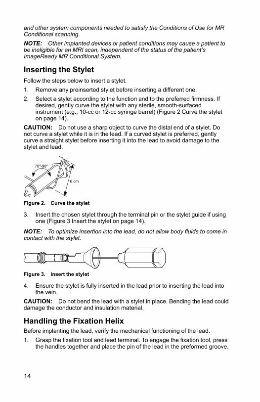
Inserting the StyletFollow the steps below to insert a stylet.1. Remove any preinserted stylet before inserting a different one.2. Select a stylet according to the function and to the preferred firmness. If
desired, gently curve the stylet with any sterile, smooth-surfacedinstrument (e.g., 10-cc or 12-cc syringe barrel) (Figure 2 Curve the styleton page 14).
CAUTION: Do not use a sharp object to curve the distal end of a stylet. Donot curve a stylet while it is in the lead. If a curved stylet is preferred, gentlycurve a straight stylet before inserting it into the lead to avoid damage to thestylet and lead.
Figure 2. Curve the stylet
3. Insert the chosen stylet through the terminal pin or the stylet guide if usingone (Figure 3 Insert the stylet on page 14).
NOTE: To optimize insertion into the lead, do not allow body fluids to come incontact with the stylet.
Figure 3. Insert the stylet
4. Ensure the stylet is fully inserted in the lead prior to inserting the lead intothe vein.
CAUTION: Do not bend the lead with a stylet in place. Bending the lead coulddamage the conductor and insulation material.
Handling the Fixation HelixBefore implanting the lead, verify the mechanical functioning of the lead.1. Grasp the fixation tool and lead terminal. To engage the fixation tool, press
the handles together and place the pin of the lead in the preformed groove.

15
Release the tension on the handles to secure the terminal pin in thefixation tool.
Figure 4. Fixation tool attached
2. Rotate the terminal pin clockwise to extend the helix and counterclockwiseto retract it and visually observe the helix extending and retracting.NOTE: The expected number of turns and the recommended maximumnumber of turns to extend or retract the helix are provided in thespecifications (Table 5 Specifications on page 30). Any curves introducedinto the stylet could increase the number of turns needed to extend orretract the helix.
CAUTION: Do not overextend or over-retract the helix. The leadconductor coil or fixation mechanism can be damaged or broken if youcontinue to rotate the terminal pin once the helix is fully extended orretracted.
CAUTION: If the helix cannot be extended or retracted, do not use thelead.CAUTION: To promote proper function do not use a lead with adeformed helix or damaged helix fixation mechanism. To avoid electrodedamage, do not attempt to straighten or realign the helix. Avoid holding orhandling the distal tip.
CAUTION: Avoid creating sharp bends in the lead terminal or lead bodywhile extending or retracting the helix. Sharp bends can increase the riskof breaking the conductor coil or fixation mechanism during helix extensionand retraction.
3. Ensure the helix is retracted into the distal lead tip prior to inserting thelead into the vein.
CAUTION: Do not insert a lead into the vein when the helix is extended,as this may cause damage to the tissue and/or lead. Prior to insertion inthe vein, rotate the terminal pin counterclockwise to retract the helix intothe distal lead tip.
4. Disengage the fixation tool from the terminal pin prior to inserting the leadinto the vein.

16
Inserting the LeadThe lead may be inserted using one of the following methods: via the cephalicvein, or through the subclavian or internal jugular vein.• Via cutdown through the left or right cephalic vein Only one incision
over the deltopectoral groove is required to access the right or left cephalicvein in the deltopectoral groove.
The vein pick packaged with this lead can be used to aid access during thecutdown procedure. Isolate the selected vein and introduce the point of thevein pick via this incision into the lumen of the vein. With the point of thevein pick facing in the direction of the desired lead passage, gently raiseand tilt the pick. Pass the lead under the vein pick and into the vein.
CAUTION: The vein pick is not intended either for puncturing the vein orfor dissecting tissue during a cutdown procedure. Be sure that the veinpick does not puncture the insulation of the lead. This could prevent properlead function.
Figure 5. Using the vein pick
• Percutaneously or via cutdown through the subclavian vein Asubclavian introducer set is available for use during percutaneous leadinsertion. Refer to the specifications for the recommended introducer size.CAUTION: When attempting to implant the lead via a subclavianpuncture, do not introduce the lead under the medial one-third region ofthe clavicle. Damage or chronic dislodgment to the lead is possible if thelead is implanted in this manner. If implantation via the subclavian vein isdesired, the lead must enter the subclavian vein near the lateral border ofthe first rib to avoid entrapment by the subclavius muscle or ligamentousstructures associated with the narrow costoclavicular region. It has beenestablished in the literature that lead fracture can be caused by leadentrapment in such soft tissue structures as the subclavius muscle,costocoracoid ligament, or the costoclavicular ligament.7
Leads placed by percutaneous subclavian venipuncture should enter thesubclavian vein, where it passes over the first rib (rather than moremedially), to avoid entrapment by the subclavius muscle or ligamentousstructures associated with the narrow costoclavicular region.8 It is
7. Magney JE, et al. Anatomical mechanisms explaining damage to pacemaker leads, defibrillatorleads, and failure of central venous catheters adjacent to the sternoclavicular joint. PACE.1993;16:445–457.
8. Magney JE, et al. A new approach to percutaneous subclavian venipuncture to avoid leadfracture or central venous catheter occlusion. PACE. 1993;16:2133–2142.

17
recommended to introduce the lead into the subclavian vein near thelateral border of the first rib.
The syringe should be positioned directly above and parallel to the axillaryvein to reduce the chance that the needle will contact the axillary orsubclavian arteries or the brachial plexus. Use of fluoroscopy is helpful inlocating the first rib and in guiding the needle.
The steps below explain how to identify the skin entry point and define thecourse of the needle toward the subclavian vein where it crosses the firstrib.
1. Identify points St (sternal angle) and Cp (coracoid process) (Figure 6Entry point for percutaneous subclavian venipuncture on page 17).
[1] Subclavius muscle [2] Costocoracoid ligament [3] Costoclavicular ligament
Figure 6. Entry point for percutaneous subclavian venipuncture
2. Visually draw a line between St and Cp, and divide the segment intothirds. The needle should pierce the skin at the junction of the middleand lateral thirds, directly above the axillary vein (point Ax).
3. Place an index finger on the clavicle at the junction of the medial andmiddle thirds (point V), beneath which point the subclavian veinshould be located.
4. Press a thumb against the index finger and project 1–2 centimetersbelow the clavicle to shield the subclavius muscle from the needle(when hypertrophy of the pectoralis muscle is apparent, the thumbshould project about 2 centimeters below the clavicle because thesubclavius muscle should be hypertrophied as well) (Figure 7Location of thumb and needle entry on page 18).

18
Figure 7. Location of thumb and needle entry
5. Feel with the thumb the pressure from the passage of the needlethrough the superficial fascia; direct the needle deep into the tissuestoward the subclavian vein and the underlying first rib. Fluoroscopicguidance will reduce the chance that the needle would pass below thefirst rib and into the lung.
Positioning Lead in Right AtriumTwo different J-shape stylets are provided. One has a longer reach and may besuitable for most patient anatomies. The smaller stylet may be more suitablefor a patient with a smaller atrium or a patient who has had previous cardiacsurgery.Correct functioning of the lead depends on appropriate placement of theelectrodes. Follow the instructions below to position the lead.1. Ensure the helix is retracted.
CAUTION: Do not insert a lead into the vein when the helix is extended, asthis may cause damage to the tissue and/or lead. Prior to insertion in the vein,rotate the terminal pin counterclockwise to retract the helix into the distal leadtip.2. Use a straight stylet to advance the lead into the right atrium.3. With the lead low in the right atrium, withdraw the straight stylet and insert
a J-shaped or a curved straight stylet.4. Gently pull the lead/stylet combination at the venous entry site to ensure
contact between the lead tip and the endocardium. A satisfactory positionhas the lead tip situated against the endocardium in the atrium (Figure 8Atrial placement on page 19).
5. After placing the lead, extend the helix as described in the Lead Fixationsection ("Lead Fixation" on page 20).
WARNING: Take care to obtain appropriate electrode position. Failure to doso may result in suboptimal lead measurements.

19
Figure 8. Atrial placement
Positioning Lead in Right VentricleCorrect functioning of the lead depends on appropriate placement of theelectrodes. Follow the instructions below to position the lead.1. Ensure the helix is retracted.
CAUTION: Do not insert a lead into the vein when the helix is extended, asthis may cause damage to the tissue and/or lead. Prior to insertion in the vein,rotate the terminal pin counterclockwise to retract the helix into the distal leadtip.2. Partially withdraw the stylet to utilize the flexible silicone neck during lead
positioning. Withdrawal of the stylet tip proximal to the anode minimizes tipstiffness and provides added flexibility of the tip region.
3. Advance the lead into the right atrium using a straight stylet.4. Advance the lead through the tricuspid valve or place the lead tip against
the lateral atrial wall and back the curved lead body through the tricuspidvalve.
NOTE: A curved stylet may enhance maneuverability.5. Under fluoroscopy and with a stylet in the lead, advance the lead as far as
possible so the tip electrode is in healthy myocardium in the apex of theright ventricle.
WARNING: Take care to obtain appropriate electrode position. Failure to doso may result in suboptimal lead measurements.

20
Figure 9. Ventricular placement
6. Verify under fluoroscopy that the distal tip electrode is situated in the rightventricle.
CAUTION: If the patient has a thin apical wall, another fixation site should beconsidered.
Lead FixationThe lead helix is electrically conductive to allow mapping (measuring pacingand sensing thresholds) of potential electrode positions without extending thehelix into the tissue. Mapping prior to lead fixation is recommended as it canreduce the potential need for multiple lead positionings.When data are acceptable and the correct position has been achieved,proceed with lead fixation.NOTE: Maintain the stylet in a partially retracted position when placing thelead in the RV apex or RV free wall to minimize tip stiffness.1. Attach the fixation tool to the terminal pin as indicated in the steps below.
a. Press the handles together and place the pin in the preformedgroove.
b. Release the tension on the handles to secure the terminal pin in thefixation tool.

21
Figure 10. Fixation tool attached
2. Apply adequate pressure to the lead body to position the distal electrodeagainst the desired fixation site.
3. Rotate the fixation tool clockwise to extend and affix the distal electrodehelix into the heart wall.
NOTE: Stylet curvature, extended implant time, and repositioning the leadmultiple times may increase the number of turns to extend or retract the helix.NOTE: The number of turns to extend or retract the helix may vary based onpatient anatomy and implant conditions. Maintain a straight trajectory comingout of the patient anatomy to the extent feasible.
CAUTION: Avoid creating sharp bends in the lead terminal or lead body whileextending or retracting the helix. Sharp bends can increase the risk of breakingthe conductor coil or fixation mechanism during helix extension and retraction.CAUTION: Do not rotate the terminal pin clockwise or counterclockwise morethan the recommended maximum number of turns indicated in thespecifications (Table 5 Specifications on page 30). Continuing to rotate theterminal pin once the helix is fully extended or retracted (as indicated byfluoroscopy) can damage the lead, cause a conductor coil break duringfixation, cause lead dislodgment, tissue trauma, and/or cause acute pacingthreshold to rise.4. View the radiopaque markers under fluoroscopy to identify when the
fixation helix is fully extended. Full extension is achieved when theradiopaque markers are joined and the fixation helix is extended outsidethe distal fluoroscopy markers (Table 2 Fluoroscopic view of helixelectrode on page 21).
Table 2. Fluoroscopic view of helix electrode
Fully Retracted Fully Extended
5. Once the lead is affixed in the desired location, loosely hold the proximalend of the lead and remove the fixation tool from the terminal pin bypressing the handles together.NOTE: Upon release of the tool, minimal counter-rotation in the terminalpin may be observed.

22
Checking for Lead StabilityFollow these steps to check lead stability:1. After fixation, partially withdraw the stylet 8 to 10 cm. (Also see step 5 in
this list.)
CAUTION: To prevent dislodgment, avoid rotating the terminal pin afterfixating the lead.2. Check the stability of the lead using fluoroscopy. Do not tug on the lead. If
possible, have the patient cough or take several deep breaths.3. For atrial implantation, after the lead tip is affixed to the heart wall, check
for proper lead movement and lead slack in the atrium:• As the patient exhales, the lead J-shape should appear secure in the
atrial appendage.• As the patient inhales, the J-shape straightens to form an L-shape.
Sufficient slack is present if the lead assumes an L-shape. Excessiveslack is present if the lead drops near the tricuspid valve.
4. For ventricular implantation, after the lead tip is affixed to the heart wall,check for proper lead movement and lead slack in the ventricle.
5. When the electrode position is satisfactory, withdraw the stylet.CAUTION: Should dislodgment occur, immediate medical care is required toresolve the electrode position and minimize endocardial trauma.
Repositioning the LeadIf the lead needs repositioning, follow these steps.1. Reconnect the fixation tool and rotate the tool counterclockwise to retract
the helix.2. View the radiopaque markers under fluoroscopy to verify that the helix is
retracted and disengaged completely from the heart wall before attemptingto reposition the lead.
CAUTION: Do not rotate the terminal pin clockwise or counterclockwise morethan the recommended maximum number of turns indicated in thespecifications (Table 5 Specifications on page 30). Continuing to rotate theterminal pin once the helix is fully extended or retracted (as indicated byfluoroscopy) can damage the lead, cause a conductor coil break duringfixation, cause lead dislodgment, tissue trauma, and/or cause acute pacingthreshold to rise.CAUTION: Do not continue to use the lead if the helix cannot be retractedduring implant. Continuous counterclockwise rotation of the lead body duringlead removal is necessary to avoid inadvertent tissue trauma and accidentalfixation, and to release the electrode helix if tissue snagging has occurred.

23
3. Reaffix the electrode using the previous procedures for handling,positioning, and checking for lead stability.
Evaluating Lead PerformanceVerify electrical performance of the lead using a pacing system analyzer (PSA)before attaching the lead to the pulse generator. Verifying electricalperformance will confirm lead integrity.1. When the lead is placed in the desired location, partially withdraw the
stylet so the terminal pin is accessible.2. Connect the lead to the PSA.
• For bipolar leads, the lead terminal pin is the cathode (–) conductorand should be connected to the negative conductor of the PSA patientcable. The ring of the lead terminal is the anode (+) conductor andshould be connected to the positive conductor of the patient cable.
3. Perform the measurements as indicated in the table.Table 3. Recommended threshold and sensing measurements
Measurements Atrial Data Ventricular Data
Voltage threshold (pulsewidth setting at 0.5 ms)
≤ 1.5 V ≤ 1.0 V
P-wave / R-wave ≥ 2.0 mV ≥ 5.0 mV
Impedance 200–2000 Ω 200–2000 Ω
• Pulse generator measurements may not exactly correlate to the PSAmeasurements due to signal filtering. Baseline measurements shouldfall within the recommended values indicated in the table.
• Lower intrinsic potentials, longer durations, and higher pacingthreshold may indicate lead placement in ischemic or scarred tissue.Because signal quality may deteriorate, reposition the lead ifnecessary to obtain a signal with the largest possible amplitude,shortest duration, and lowest pacing threshold.
4. If measurements do not conform to the values in the table, perform thefollowing steps:• Remove the PSA from the lead.• Reinsert the stylet and reposition the lead using the procedures
previously discussed and repeat the lead evaluation process.• If testing results are unsatisfactory, further lead system repositioning
or replacement may be required.Consider the following information:
• Low stimulation threshold readings indicate a desirable safety margin,since stimulation threshold may rise after implantation.
• Initial electrical measurements may deviate from recommendationsbecause of acute cellular trauma. If this occurs, wait approximately 10minutes and repeat testing. Values may be dependent on patient-

24
specific factors such as tissue condition, electrolyte balance, and druginteractions.
• Amplitude and duration measurements are not inclusive of current ofinjury and are taken during the patient's normal baseline rhythm.
• Over-rotation of the terminal pin may increase local tissue trauma andcause temporarily high voltage thresholds.
5. Test for diaphragmatic stimulation by pacing the lead at a high voltageoutput, using professional medical judgment to select the output voltage.Adjust the lead configurations and lead position as necessary. PSA testingat higher outputs may also be considered to better characterize stimulationmargins. Testing should be conducted for all lead placements.
6. Once acceptable measurements are obtained, remove the pacing systemanalyzer connections, and remove the stylet.
Securing the LeadAfter the electrodes are satisfactorily positioned, use the suture sleeve tosecure the lead to achieve permanent hemostasis and lead stabilization.Suture sleeve tie-down techniques can vary with the lead insertion techniqueused. Consider the following warning and precautions while securing the lead.WARNING: Do not kink, twist, or braid the lead with other leads as doing socould cause lead insulation abrasion damage or conductor damage.CAUTION: When ligating the vein, avoid stricture that is too tight. A tightstricture might damage the insulation or sever the vein. Avoid dislodging thedistal tip during the anchoring procedure.CAUTION: Do not suture directly over the lead body, as this may causestructural damage. Use the suture sleeve to secure the lead proximal to thevenous entry site to prevent lead movement.CAUTION: Avoid removing or cutting the suture sleeve from the lead. Ifremoval of the suture sleeve is necessary, use caution as lead damage canoccur.CAUTION: Use of multiple suture sleeves has not been evaluated and is notrecommended.

25
Percutaneous Implant Technique1. Peel back the introducer sheath and slide the suture sleeve deep into the
tissue (Figure 11 Example of suture sleeve, percutaneous implanttechnique on page 25).
Figure 11. Example of suture sleeve, percutaneous implant technique

26
2. Using at least two grooves, ligate the suture sleeve and the lead to thefascia. For additional stability, the sleeve may be secured to the lead firstbefore securing the sleeve to the fascia.
3. Check the suture sleeve after tie-down to demonstrate stability and lack ofslippage by grasping the suture sleeve with fingers and trying to move thelead in either direction.
Venous Cutdown Technique1. Slide the suture sleeve into the vein past the distal groove.2. Ligate the vein around the suture sleeve to obtain hemostasis.3. Using the same groove, secure the lead and vein to the adjacent fascia
(Figure 12 Example of suture sleeve, venous cutdown technique on page26).
Figure 12. Example of suture sleeve, venous cutdown technique

27
4. Use at least two grooves to secure the sleeve to the lead. Secure the leadand suture sleeve to the adjacent fascia.
5. Check the suture sleeve after tie-down to demonstrate stability and lack ofslippage by grasping the suture sleeve with fingers and trying to move thelead in either direction.
Connection to a Pulse GeneratorConsult the applicable pulse generator physician's manual for moreinstructions for connecting lead terminals to the pulse generator.1. Verify the stylet and any terminal pin accessories are removed prior to
connecting the lead to the pulse generator.2. When the lead is secured at the venous entry site, recheck position and
threshold measurements and then connect the lead to the pulse generatorusing the procedure described in the applicable pulse generatorphysician's manual.
3. Grasp the terminal immediately distal to the terminal ring contacts and fullyinsert the lead terminal into the pulse generator port until the terminal pin isvisible beyond the setscrew block. If the terminal pin is difficult to insert,verify the setscrew is completely retracted.
NOTE: If necessary, lubricate the lead connectors sparingly with sterile waterto make insertion easier.4. Apply gentle traction to the lead by grasping the labeled area of the lead
body to ensure a secure connection.
CAUTION: Insert the lead terminal straight into the lead port. Do not bend thelead near the lead-header interface. Improper insertion can cause insulation orconnector damage.NOTE: If the lead terminal will not be connected to a pulse generator at thetime of lead implantation, you must cap the connector before closing the pocketincision. The lead cap is designed specifically for this purpose. Place a suturearound the lead cap to keep it in place.5. Giving consideration to patient anatomy and pulse generator size and
motion, gently coil any excess lead and place adjacent to the pulsegenerator. It is important to place the lead into the pocket in a manner thatminimizes lead tension, twisting, sharp angles, and/or pressure.
Electrical Performance1. Evaluate the lead signals using the pulse generator.2. Place the pulse generator into the implant pocket as indicated in the pulse
generator physician's manual. Also refer to the instructions in this manual("Connection to a Pulse Generator" on page 27).
3. Evaluate the lead signals by viewing the real-time EGM. Consider thefollowing:• The signal from the implanted lead should be continuous and without
artifact, similar to a body-surface ECG.

28
• A discontinuous signal may indicate a lead conductor coil break,fracture or an otherwise damaged lead, or an insulation break thatwould necessitate lead replacement.
• Inadequate signals may result either in a failure of the pulse generatorsystem to detect an arrhythmia or in an unnecessary delivery oftherapy.
4. Test for diaphragmatic stimulation by pacing the lead at a high voltageoutput, using professional medical judgment to select the output voltage.Adjust the lead configurations and lead position as necessary. Testingshould be conducted for all lead placements.
POSTIMPLANT
Postimplant EvaluationPerform follow-up evaluation as recommended in the applicable pulsegenerator physician's manual.CAUTION: For some patients, lead performance at implant may not predictperformance in the chronic state. Therefore, it is recommended that post-implant lead evaluation follow-up be done at the routine pulse generator follow-up and additionally as necessary.WARNING: Ensure that an external defibrillator and medical personnelskilled in CPR are present during post-implant device testing should the patientrequire external rescue.NOTE: Chronic repositioning of the lead may be difficult because of bodyfluid or fibrotic tissue intrusion.
Explantation and DisposalWARNING: Do not reuse, reprocess, or resterilize. Reuse, reprocessing, orresterilization may compromise the structural integrity of the device and/or leadto device failure which, in turn, may result in patient injury, illness, or death.Reuse, reprocessing, or resterilization may also create a risk of contaminationof the device and/or cause patient infection or cross-infection, including, but notlimited to, the transmission of infectious disease(s) from one patient to another.Contamination of the device may lead to injury, illness, or death of the patient.NOTE: Return all explanted devices to Boston Scientific regardless ofcondition. Examination of explanted devices can provide information forcontinued improvement in system reliability and warranty considerations. For aReturned Product Kit, contact Boston Scientific using the information on theback cover.Contact Boston Scientific when any of the following occur:• When a product is removed from service.• In the event of patient death (regardless of cause), along with an autopsy
report, if performed.• For other observation or complication reasons.

29
Consider the following when explanting and returning devices:• Interrogate the pulse generator and print a comprehensive report.• Deactivate the pulse generator before explantation.• Disconnect the leads from the pulse generator.• If leads are explanted, attempt to remove them intact, and return them
regardless of condition. Do not remove leads with hemostats or any otherclamping tool that may damage the leads. Resort to tools only if manualmanipulation cannot free the lead.
• Wash, but do not submerge, the devices to remove body fluids and debrisusing a disinfectant solution. Do not allow fluids to enter the pulsegenerator's header port(s).
• Use a Boston Scientific Returned Product Kit to properly package thedevices, and send it to Boston Scientific.
CAUTION: Clean and disinfect the device using standard biohazard handlingtechniques since all explanted components are considered biohazardous.
All items used during explantation, such as accessories, consumables, andsharps, may be contaminated with infectious substances. Consider thefollowing to minimize the risk of infection, microbial hazards, or physical harm:• Biohazardous waste should be disposed in a biohazard container that is
labeled with the biological hazard symbol and taken to a designated facilityfor biohazardous waste for proper treatment in accordance with hospital,administrative, and/or local government policy.
• Biohazardous waste should be treated with an appropriate thermal orchemical process.
• Sharps should be disposed of in a sharps disposal container.NOTE: Disposal of explanted devices is subject to applicable laws andregulations.
NOTE: Untreated biohazardous waste should not be disposed of in amunicipal waste system.
SPECIFICATIONS
SpecificationsTable 4. Model Number and Lead Length
Model Length (cm)
7840 45
7841 52
7842 59

30
Table 5. Specifications
Characteristic Information
Terminal type IS-1BI
Compatibility Pulse generators with an IS-1 port, whichaccepts an IS-1 terminal
Fixation Extendable/retractable helix
Expected number of rotations to fullyextend/retract the helixa
6 ± 2 turns with straight stylet7 ± 3 turns with J stylet
Recommended maximum number ofrotations to extend/retract the helixa
30 turns
CAUTION: Do not rotate the terminal pin clockwise or counterclockwise more thanthe recommended maximum number of turns indicated. Continuing to rotate theterminal pin once the helix is fully extended or retracted (as indicated by fluoroscopy)can damage the lead, cause a conductor coil break during fixation, cause leaddislodgment, tissue trauma, and/or cause acute pacing threshold to rise.
Nominal fixation helix penetration depth 1.8 mm
Nominal tip to marker band distal edge 0.1 mm
Nominal Electrode Dimensions:
Fixation helix surface area 4.5 mm2
Distance between electrodes 10.7 mm
Anode electrode 20 mm2
Nominal Diameter:
Insertion 2.0 mm (6F)
Anode electrode 2.0 mm
Lead body 1.9 mm
Fixation helix 1.2 mm
Material:
External insulation Polyurethane (55D)
Internal insulation Silicone rubber
Terminal ring contact 316L stainless steel
IS-1 terminal pin contact 316L stainless steel
Tip electrode IROX (iridium oxide) coated Pt-Ir
Anode electrode IROX (iridium oxide) coated Pt-Ir

31
Table 5. Specifications (continued)
Characteristic Information
Conductor type: tri-filar inner coil andsingle-filar outer coil
MP35N™ b
Steroid 0.91 mg dexamethasone acetate
Radiopaque markers Pt-Ir
Suture sleeve Radiopaque white silicone rubber
Maximum Lead Conductor Resistance:
From terminal ring to anode (or ring)electrode
45 cm: 130 Ω52 cm: 152 Ω59 cm: 174 Ω
From terminal pin to tip electrode 45 cm: 47 Ω52 cm: 55 Ω59 cm: 62 Ω
a. Use fluoroscopy markers for verification of full extension/retraction of the helix. The number ofturns to extend or retract the helix may vary based on patient anatomy and implant conditions.
b. MP35N is a trademark of SPS Technologies, Inc.
Table 6. Patient-contacting materials and substances
Material/Substance Percentage of total patient-contactingsurface area of device (%)
Polyurethane 70-80
Silicone 20-30
IROX (iridium oxide) < 5
Lead IntroducerTable 7. Lead introducer
Recommended lead introducer
Introducer without guide wire 6F (2.0 mm)
Introducer with guide wire 9F (3.0 mm)
Symbols on PackagingThe following symbols may be used on packaging and labeling (Table 8Symbols on packaging on page 32):

32
Table 8. Symbols on packaging
Symbol Description
Reference Number
Contents
Serial Number
Use By
Lot Number
Date of Manufacture
Sterilized using ethylene oxide.
Do Not Resterilize
Single use. Do not re-use.
Do not use if package is damaged.
Consult instructions for use on this website: www.bostonscientific-elabeling.com
Open Here
Manufacturer
MR Conditional
Double sterile barrier system
Contains a medicinal substance


Boston Scientific Corporation4100 Hamline Avenue NorthSt. Paul, MN 55112–5798 USA
www.bostonscientific.com
1.800.CARDIAC (227.3422)
+1.651.582.4000
© 2019 Boston Scientific Corporation or its affiliates.
All rights reserved.92383113-001 EN US 2019-07
*92383113-001*